US6224728B1 - Valve for fluid control - Google Patents
Valve for fluid controlDownload PDFInfo
- Publication number
- US6224728B1 US6224728B1US09/373,872US37387299AUS6224728B1US 6224728 B1US6224728 B1US 6224728B1US 37387299 AUS37387299 AUS 37387299AUS 6224728 B1US6224728 B1US 6224728B1
- Authority
- US
- United States
- Prior art keywords
- valve
- fluid
- electrokinetic pump
- valve body
- chamber
- Prior art date
- Legal status (The legal status is an assumption and is not a legal conclusion. Google has not performed a legal analysis and makes no representation as to the accuracy of the status listed.)
- Expired - Lifetime
Links
Images


Classifications
- F—MECHANICAL ENGINEERING; LIGHTING; HEATING; WEAPONS; BLASTING
- F04—POSITIVE - DISPLACEMENT MACHINES FOR LIQUIDS; PUMPS FOR LIQUIDS OR ELASTIC FLUIDS
- F04B—POSITIVE-DISPLACEMENT MACHINES FOR LIQUIDS; PUMPS
- F04B19/00—Machines or pumps having pertinent characteristics not provided for in, or of interest apart from, groups F04B1/00 - F04B17/00
- F04B19/006—Micropumps
Definitions
- This inventionpertains generally to valves for controlling fluid flow and particularly to microvalves that use electrokinetic pump actuation for fluid flow control in microfluidic systems.
- microfluidic devicesthat are designed, in part, to perform a multitude of chemical and physical process.
- Typical applicationsinclude analytical and medical instrumentation, and industrial process control equipment.
- Microvalvesare an important component of the microfluidic systems used in these applications.
- microvalvesAlthough there are numerous micro-fabricated valve designs that use a wide variety of actuation mechanisms, only two of these designs are incorporated in commercially available microvalves, with thermopneumatic expansion being used as the actuation mechanism in one design and a shape memory alloy diaphragm and bias spring in the other.
- these microvalvessuffer from the fact that they consume relatively large amounts of power during operation, typically between 200 and 1500 mW depending upon the design. This high power consumption can be a significant disadvantage if power must be supplied by batteries or the microvalve is placed on a microchip.
- valves using the aforementioned actuation mechanismscan only generate modest actuation pressures.
- microvalvethat can be used for microfluidic systems that requires significantly less power to operate, can exert larger actuation pressures than can be presently developed by conventional microvalves, is suitable for use on a microchip, and provides both rapid “on” and “off” actuation.
- the present inventionis directed to a valve that can generate actuation pressures in excess of 8000 psi and can be used for controlling fluid flow, both gas and liquid, particularly in microfluidic systems.
- These novel microvalvescan be operated, generally, at a power of less than about 10 mW, and particularly at a power of less than about 1 mW.
- the present valveemploys an electrokinetic pump to generate the pressure required to operate, or actuate, the valve itself.
- the use of an electrokinetic pump to operate the microvalveprovides several significant advantages over conventional microvalves. Among these is the ability to incorporate the actuation device and valve into a unitary structure that can be placed onto a microchip, the ability to generate higher actuation pressures and thus control higher fluid pressures than conventional actuation means, and the requirements for only microwatts of power for activation. Further, by employing the hydraulic pressure developed by an electrokinetic pump to operate the microvalve, it is now possible to contemplate radically different microvalve designs.
- FIG. 1illustrates a normally-open embodiment of the present valve.
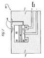
- FIG. 2shows a valve embodiment having an electrokinetic pump as an integral component of the valve body.
- the present inventionis a novel valve for controlling fluid flows that provides: 1) the ability to incorporate the actuation device and valve into a unitary structure that can be placed onto a microchip, 2) the ability to generate higher actuation pressures and thus control higher fluid pressures than conventional microvalves, and 3) a device that draws only microwatts of power.
- An electrokinetic pumpthat converts electric potential to hydraulic force is used to operate, or actuate, the microvalve.
- the electrokinetic pump or EKPcomprises at least one tube or flow channel, that can be a capillary or micro-fabricated channel, forming a fluid passageway.
- the flow channelhas a porous dielectric material disposed therein and contains an electrolyte in contact with one or more pair of spaced electrodes.
- the porous dielectric mediumcan include small particles, high surface area structures fabricated within the microchannel, and porous materials, such as porous organic polymer materials.
- An electric potentialcan be applied to the electrodes by means of a conventional power supply or batteries and the electric potential can assume various forms suitable to the operation of the system described herein, such as having a varying amplitude, shape, and period.
- the electrolytewhich is in contact with the spaced electrodes, can be an aqueous, or an organic liquid or mixtures thereof.
- the electric field applied across the EKP by the spaced electrodeswill cause the electrolyte contained in the porous dielectric medium to flow and, when presented with an external flow resistance can create pressures of thousands of psi at the down stream end of the EKP.
- the flowrate of the electrolyteis proportional to the magnitude of the applied electric field (V/m applied across the EKP) and the pressure generated is proportional to the voltage across the device.
- the direction of flow of the electrolyteis determined by both the nature of the electrochemical interaction between the porous dielectric medium and the electrolyte, and the polarity of the applied electric potential.
- valve 100comprises generally an electrokinetic pump 105 and a valve body 150 .
- electrokinetic pump 105generally consists of at least one tube or channel 110 , having an inlet and outlet, that can be a capillary channel or microchannel, that forms a fluid passageway containing an electrolyte 115 and having a porous dielectric medium 120 disposed therein between one or more pair of spaced electrodes 130 .
- Porous dielectric medium 120can include small particles, high surface area structures fabricated within the microchannel, or porous materials, such as porous organic polymer materials.
- An electric potential 135is applied between electrodes 130 in contact with electrolyte 115 to cause the electrolyte to move in the microchannel by electroosmotic flow.
- Electrolyte 115can be an aqueous or an organic liquid or mixtures thereof.
- Valve body 150is provided with two chambers, a fluid chamber 165 and an actuator chamber 160 , joined together.
- the fluid and actuator chamberscan be fabricated from a glass, silicon, or a suitable polymeric material.
- a fluid tight, flexible member 170serving as a partition or diaphragm, separates the two chambers.
- Flexible member 170is preferably made from a material, such as silicon, Kapton, or a polymeric material, that is compatible with the fluids that are contained in chambers 160 and 165 and is flexible by virtue of its composition or mechanical design.
- Actuator chamber 160can be provided with an inlet port 180 and can have an outlet port 185 .
- the outlet of electrokinetic pump 105can be connected to inlet port 180 .
- actuator chamber 160Prior to operating valve 150 , actuator chamber 160 can be filled with electrolyte from electrokinetic pump 105 , or any other fluid compatible with operation of the electrokinetic pump, by opening a shut-off valve (not shown) included in outlet port 185 .
- a shut-off valve(not shown) closes outlet port 185 during device operation.
- Fluid chamber 165can be similarly provided with an inlet port 190 and an outlet port 195 for ingress and egress of a fluid stream, either liquid or gas.
- the flow of a fluid streamis controlled by applying hydraulic pressure, generated by the action of electrokinetic pump 105 through inlet port 180 , to flexible member 170 causing it to deform and close off fluid inlet port 190 and thereby stop fluid flow.
- hydraulic pressuregenerated by the action of electrokinetic pump 105 through inlet port 180
- flexible member 170causing it to deform and close off fluid inlet port 190 and thereby stop fluid flow.
- the polarity of the electric potential applied to electrokinetic pump 105is reversed.
- actuator chamber 160 and fluid chamber 165are filled with fluid, the addition of only that amount of fluid necessary to cause displacement of flexible member 170 is required to stop fluid flow and thus, the response time of the valve can be very rapid.
- a valve bodycomprising actuator and fluid chambers and an interposed diaphragm, similar to that shown in FIG. 1, was constructed to demonstrate its utility and to provide engineering data.
- the actuator and fluid chamberswere each fabricated from Pyrex glass.
- a circular actuator chamber 4 mm in diameter and 150 ⁇ m highwas machined in one piece of Pyrex glass and a circular fluid chamber of similar dimension was machined in a second piece of Pyrex glass.
- Silica microcapillary tubesprovided inlet and outlet ports for both the actuator and fluid chambers.
- the inlet port for the fluid chambercan be located anywhere on the fluid chamber, but in this instance was centered directly below the center of the diaphragm separating the two chambers.
- the fluid chamber outlet portwas connected to the fluid chamber by a short flow channel machined in the Pyrex glass body.
- a 75 ⁇ m thick silicon waferprovided the partition between the actuation and fluid chambers.
- a cavity 4 mm in diameter and 25 ⁇ m thickwas etched into the silicon partition using an anisotropic wet-etch process, thereby, producing a circular diaphragm 4 mm in diameter and 50 ⁇ m thick.
- the valve body itselfwas fabricated by anodically bonding the two Pyrex glass bodies to the silicon partition material.
- the inlet port of the actuator chamberwas connected to the outlet port of an electrokinetic pump whose structure has been described above.
- the porous dielectric material used in the electrokinetic pumpwas 4.5 ⁇ m non-porous silica beads and the electrolyte was acetonitrile.
- a 10 psi nitrogen gas streamhaving a flow rate of about 82 sccm, was applied to the fluid chamber inlet.
- a diaphragm actuation pressure of about 30-35 psiwas sufficient for complete closure of the valve. This pressure was provided by applying about 5000 V dc to the electrokinetic pump connected to the actuator port of the valve body. Power consumption was measured to be 8 mW.
- the surface area of the porous dielectric medium used in the electrokinetic pumpplays a strong role in establishing the relationship between applied voltage and the hydraulic pressure produced by the electrokinetic pump.
- By increasing the surface area of the porous dielectric mediumit has been shown that it is possible to apply a lower voltage to produce a given pressure.
- the dielectric mediumconsisted of 4.5 ⁇ m non-porous silica beads.
- pressures as high as 500 psican be attained with the application of about 20 V dc.
- Monolithic porous polymeric materialshaving a high surface area, have also been shown to provide suitable dielectric material for an electrokinetic pump, and microvalve actuation voltages as low as 400 V dc have been demonstrated.
- Device power consumption at 400 V dcwas about 16 ⁇ w.
- valve body 150is provided with two chambers, a fluid chamber 165 and an actuator chamber 160 joined together with flexible member 170 interposed between and separating the two chambers.
- the electrokinetic pump that provides the hydraulic force required to operate the valveis disposed within actuator chamber 160 .
- actuator chamber 160contains a porous dielectric medium 120 disposed between a pair of spaced electrodes 130 .
- An electrolyte 115fills actuator chamber 160 . Opening and closing of the valve is as described above except that in this embodiment hydraulic force is applied directly to flexible member 170 rather than externally through an outlet port on the valve body.
- the incorporation of the electrokinetic pump into the valve body itselfprovides for a more compact design.
Landscapes
- Engineering & Computer Science (AREA)
- Mechanical Engineering (AREA)
- General Engineering & Computer Science (AREA)
- Micromachines (AREA)
Abstract
Description
This application is a Continuation-in-Part of prior co-pending U.S. patent application Ser. No. 09/057,017 filed on Apr. 7, 1998 now U.S. Pat. No. 6,019,882 entitled ELECTROKINETIC HIGH PRESSURE HYDRAULIC SYSTEM from which priority is claimed.
This invention was made with Government support under contract no. DE-AC04-94AL85000 awarded by the U.S. Department of Energy to Sandia Corporation. The Government has certain rights in the invention.
This invention pertains generally to valves for controlling fluid flow and particularly to microvalves that use electrokinetic pump actuation for fluid flow control in microfluidic systems.
Recent advances in device miniaturization have led to the development of microfluidic devices that are designed, in part, to perform a multitude of chemical and physical process. Typical applications include analytical and medical instrumentation, and industrial process control equipment. Microvalves are an important component of the microfluidic systems used in these applications.
Although there are numerous micro-fabricated valve designs that use a wide variety of actuation mechanisms, only two of these designs are incorporated in commercially available microvalves, with thermopneumatic expansion being used as the actuation mechanism in one design and a shape memory alloy diaphragm and bias spring in the other. However, these microvalves suffer from the fact that they consume relatively large amounts of power during operation, typically between 200 and 1500 mW depending upon the design. This high power consumption can be a significant disadvantage if power must be supplied by batteries or the microvalve is placed on a microchip. Moreover, valves using the aforementioned actuation mechanisms can only generate modest actuation pressures.
What is needed is a microvalve that can be used for microfluidic systems that requires significantly less power to operate, can exert larger actuation pressures than can be presently developed by conventional microvalves, is suitable for use on a microchip, and provides both rapid “on” and “off” actuation.
The present invention is directed to a valve that can generate actuation pressures in excess of 8000 psi and can be used for controlling fluid flow, both gas and liquid, particularly in microfluidic systems. These novel microvalves can be operated, generally, at a power of less than about 10 mW, and particularly at a power of less than about 1 mW.
In contrast to prior art microvalves, the present valve employs an electrokinetic pump to generate the pressure required to operate, or actuate, the valve itself. The use of an electrokinetic pump to operate the microvalve provides several significant advantages over conventional microvalves. Among these is the ability to incorporate the actuation device and valve into a unitary structure that can be placed onto a microchip, the ability to generate higher actuation pressures and thus control higher fluid pressures than conventional actuation means, and the requirements for only microwatts of power for activation. Further, by employing the hydraulic pressure developed by an electrokinetic pump to operate the microvalve, it is now possible to contemplate radically different microvalve designs.
The accompanying drawings, which are incorporated in and form part of the specification, illustrate the present invention and, together with the description, explain the invention. In the drawings like elements are referred to by like numbers.
FIG. 1 illustrates a normally-open embodiment of the present valve.
FIG. 2 shows a valve embodiment having an electrokinetic pump as an integral component of the valve body.
The present invention is a novel valve for controlling fluid flows that provides: 1) the ability to incorporate the actuation device and valve into a unitary structure that can be placed onto a microchip, 2) the ability to generate higher actuation pressures and thus control higher fluid pressures than conventional microvalves, and 3) a device that draws only microwatts of power. An electrokinetic pump that converts electric potential to hydraulic force is used to operate, or actuate, the microvalve. In order to understand the present invention better, the following introductory discussion is provided.
It has been demonstrated that it is possible to convert electric potential to hydrodynamic force and, by means of a process called electrokinetic pumping, to produce hydraulic pressures at least as great as 10,000 psi. The electrokinetic pump or EKP, comprises at least one tube or flow channel, that can be a capillary or micro-fabricated channel, forming a fluid passageway. The flow channel has a porous dielectric material disposed therein and contains an electrolyte in contact with one or more pair of spaced electrodes. The porous dielectric medium can include small particles, high surface area structures fabricated within the microchannel, and porous materials, such as porous organic polymer materials. An electric potential can be applied to the electrodes by means of a conventional power supply or batteries and the electric potential can assume various forms suitable to the operation of the system described herein, such as having a varying amplitude, shape, and period. The electrolyte, which is in contact with the spaced electrodes, can be an aqueous, or an organic liquid or mixtures thereof. The electric field applied across the EKP by the spaced electrodes will cause the electrolyte contained in the porous dielectric medium to flow and, when presented with an external flow resistance can create pressures of thousands of psi at the down stream end of the EKP. The flowrate of the electrolyte is proportional to the magnitude of the applied electric field (V/m applied across the EKP) and the pressure generated is proportional to the voltage across the device. The direction of flow of the electrolyte is determined by both the nature of the electrochemical interaction between the porous dielectric medium and the electrolyte, and the polarity of the applied electric potential. A detailed discussion of the theory and operation of the electrokinetic pumping process can be found in prior co-pending U.S. patent applications Ser. No. 08/882,725 filed on Jun. 25, 1997 and Ser. No. 09/057,017 filed on Apr. 7, 1998, both entitled ELECTROKINETIC HIGH PRESSURE HYDRAULIC SYSTEM, assigned to the same assignee, and incorporated herein by reference in their entirety.
Referring now to FIG. 1, which shows one embodiment of the valve of the present invention for controlling the flow of a fluid,valve 100 comprises generally anelectrokinetic pump 105 and avalve body 150. As set forth above,electrokinetic pump 105 generally consists of at least one tube orchannel 110, having an inlet and outlet, that can be a capillary channel or microchannel, that forms a fluid passageway containing anelectrolyte 115 and having a porousdielectric medium 120 disposed therein between one or more pair of spacedelectrodes 130. Porousdielectric medium 120 can include small particles, high surface area structures fabricated within the microchannel, or porous materials, such as porous organic polymer materials. Anelectric potential 135 is applied betweenelectrodes 130 in contact withelectrolyte 115 to cause the electrolyte to move in the microchannel by electroosmotic flow.Electrolyte 115 can be an aqueous or an organic liquid or mixtures thereof.
The flow of a fluid stream is controlled by applying hydraulic pressure, generated by the action ofelectrokinetic pump 105 throughinlet port 180, toflexible member 170 causing it to deform and close offfluid inlet port 190 and thereby stop fluid flow. To openvalve 150, the polarity of the electric potential applied toelectrokinetic pump 105 is reversed. It should be noted that because of the resistance of the dielectric medium to pressure driven flow, i.e., a pressure of several thousand psi can be required to force fluid through the dielectric medium, simply shutting the applied electric potential will generally not causevalve 150 to open. Moreover, becauseactuator chamber 160 andfluid chamber 165 are filled with fluid, the addition of only that amount of fluid necessary to cause displacement offlexible member 170 is required to stop fluid flow and thus, the response time of the valve can be very rapid.
In accordance with the present invention, a valve body comprising actuator and fluid chambers and an interposed diaphragm, similar to that shown in FIG. 1, was constructed to demonstrate its utility and to provide engineering data. The actuator and fluid chambers were each fabricated from Pyrex glass. A circular actuator chamber 4 mm in diameter and 150 μm high was machined in one piece of Pyrex glass and a circular fluid chamber of similar dimension was machined in a second piece of Pyrex glass. Silica microcapillary tubes provided inlet and outlet ports for both the actuator and fluid chambers. The inlet port for the fluid chamber can be located anywhere on the fluid chamber, but in this instance was centered directly below the center of the diaphragm separating the two chambers. The fluid chamber outlet port was connected to the fluid chamber by a short flow channel machined in the Pyrex glass body. A 75 μm thick silicon wafer provided the partition between the actuation and fluid chambers. A cavity 4 mm in diameter and 25 μm thick was etched into the silicon partition using an anisotropic wet-etch process, thereby, producing a circular diaphragm 4 mm in diameter and 50 μm thick. The valve body itself was fabricated by anodically bonding the two Pyrex glass bodies to the silicon partition material.
The inlet port of the actuator chamber was connected to the outlet port of an electrokinetic pump whose structure has been described above. In this particular instance, the porous dielectric material used in the electrokinetic pump was 4.5 μm non-porous silica beads and the electrolyte was acetonitrile.
A 10 psi nitrogen gas stream, having a flow rate of about 82 sccm, was applied to the fluid chamber inlet. A diaphragm actuation pressure of about 30-35 psi was sufficient for complete closure of the valve. This pressure was provided by applying about 5000 V dc to the electrokinetic pump connected to the actuator port of the valve body. Power consumption was measured to be 8 mW.
The surface area of the porous dielectric medium used in the electrokinetic pump plays a strong role in establishing the relationship between applied voltage and the hydraulic pressure produced by the electrokinetic pump. By increasing the surface area of the porous dielectric medium it has been shown that it is possible to apply a lower voltage to produce a given pressure. In the example above, the dielectric medium consisted of 4.5 μm non-porous silica beads. By substituting 0.5 μm non-porous silica beads for the dielectric medium, it has been shown that pressures as high as 500 psi can be attained with the application of about 20 V dc. Monolithic porous polymeric materials, having a high surface area, have also been shown to provide suitable dielectric material for an electrokinetic pump, and microvalve actuation voltages as low as 400 V dc have been demonstrated. Device power consumption at 400 V dc was about 16 μw.
Another embodiment of the valve is shown by FIG.2. As before,valve body 150 is provided with two chambers, afluid chamber 165 and anactuator chamber 160 joined together withflexible member 170 interposed between and separating the two chambers. In this embodiment, however, the electrokinetic pump that provides the hydraulic force required to operate the valve is disposed withinactuator chamber 160. As depicted in FIG. 2,actuator chamber 160 contains a porous dielectric medium120 disposed between a pair of spacedelectrodes 130. Anelectrolyte 115 fillsactuator chamber 160. Opening and closing of the valve is as described above except that in this embodiment hydraulic force is applied directly toflexible member 170 rather than externally through an outlet port on the valve body. The incorporation of the electrokinetic pump into the valve body itself provides for a more compact design.
While the principle of operation of the present invention has been illustrated by two embodiments, it would be obvious to one skilled in the art that this same principle would apply to other types of valves and microvalves such as normally-closed and multiport valves. Consequently, it will be understood that the above described arrangement of apparatus and the methods pertaining thereto are merely illustrative of applications of the principles of this invention and many other embodiments and modifications can be made by those of skill in the art without departing from the spirit and scope of the invention as defined in the claims.
Claims (9)
1. A valve for controlling fluid flow, comprising:
an electrokinetic pump in combination with a valve body such that hydraulic pressure developed by said electrokinetic pump actuates a diaphragm contained within the valve body to open and close said valve.
2. The valve of claim1, wherein the fluid is a liquid.
3. The valve structure of claim1, wherein the valve body comprises:
a) a fluid chamber having at least one fluid inlet and one fluid outlet connected thereto;
b) an actuator chamber having at least one fluid inlet, wherein the output from the electrokinetic pump is connected to the fluid inlet of said actuator chamber; and
c) a partition disposed between said fluid and actuator chambers sealingly separating said chambers and adapted to move in response to the hydraulic force generated by the electrokinetic pump to close or open the fluid inlet of the fluid chamber.
4. The valve of claim3, wherein said fluid and actuator chambers are each fabricated from Pyrex glass.
5. The valve of claim3, wherein said partition is silicon.
6. The valve of claim1, wherein the valve body comprises:
a) a fluid chamber having at least one fluid inlet and one fluid outlet connected thereto;
b) an actuator chamber containing an electrolyte and a porous dielectric medium disposed between a pair of spaced electrodes that together comprise an electrokinetic pump; and
c) a partition disposed between said fluid and actuator chambers sealingly separating said chambers and adapted to move in response to the hydraulic force generated by the electrokinetic pump to close or open the fluid inlet of the fluid chamber.
7. A solid substrate fabricated to define a valve structure disposed therein, the valve structure comprising; in combination, an electrokinetic pump joined to a valve body.
8. A method for controlling fluid flow, comprising:
connecting an electrokinetic pump to a valve body; and
applying an electric potential to the electrokinetic pump to provide a hydraulic force to open or close the valve.
9. A method for controlling fluid flow, comprising:
incorporating an electrokinetic pump into a valve body; and
applying an electric potential to the electrokinetic pump to provide a hydraulic force to open and close the valve.
Priority Applications (1)
| Application Number | Priority Date | Filing Date | Title |
|---|---|---|---|
| US09/373,872US6224728B1 (en) | 1998-04-07 | 1999-08-13 | Valve for fluid control |
Applications Claiming Priority (2)
| Application Number | Priority Date | Filing Date | Title |
|---|---|---|---|
| US09/057,017US6019882A (en) | 1997-06-25 | 1998-04-07 | Electrokinetic high pressure hydraulic system |
| US09/373,872US6224728B1 (en) | 1998-04-07 | 1999-08-13 | Valve for fluid control |
Related Parent Applications (1)
| Application Number | Title | Priority Date | Filing Date |
|---|---|---|---|
| US09/057,017Continuation-In-PartUS6019882A (en) | 1997-06-25 | 1998-04-07 | Electrokinetic high pressure hydraulic system |
Publications (1)
| Publication Number | Publication Date |
|---|---|
| US6224728B1true US6224728B1 (en) | 2001-05-01 |
Family
ID=22007992
Family Applications (1)
| Application Number | Title | Priority Date | Filing Date |
|---|---|---|---|
| US09/373,872Expired - LifetimeUS6224728B1 (en) | 1998-04-07 | 1999-08-13 | Valve for fluid control |
Country Status (1)
| Country | Link |
|---|---|
| US (1) | US6224728B1 (en) |
Cited By (48)
| Publication number | Priority date | Publication date | Assignee | Title |
|---|---|---|---|---|
| US6307240B1 (en)* | 2000-12-22 | 2001-10-23 | Visteon Global Technologies, Inc. | Pulsed etching manufacturing method and system |
| US20020100503A1 (en)* | 1998-10-09 | 2002-08-01 | Browne Ronnie A. | Sanitary diaphragm valve |
| US20020195344A1 (en)* | 2001-06-13 | 2002-12-26 | Neyer David W. | Combined electroosmotic and pressure driven flow system |
| US20030052007A1 (en)* | 2001-06-13 | 2003-03-20 | Paul Phillip H. | Precision flow control system |
| US20030132112A1 (en)* | 2001-10-19 | 2003-07-17 | Beebe David J. | Method of pumping fluid through a microfluidic device |
| US20030178972A1 (en)* | 2002-03-20 | 2003-09-25 | Burstall Oliver W.J. | Variable inertia flywheel |
| US20030203506A1 (en)* | 2002-04-30 | 2003-10-30 | Beebe David J. | Method of obtaining a sample concentration of a solution in a microfluidic device |
| US20040018095A1 (en)* | 2002-07-25 | 2004-01-29 | Smekal Thomas J. | Fluidic pump |
| US20040063217A1 (en)* | 2002-09-27 | 2004-04-01 | Webster James Russell | Miniaturized fluid delivery and analysis system |
| US6719535B2 (en)* | 2002-01-31 | 2004-04-13 | Eksigent Technologies, Llc | Variable potential electrokinetic device |
| US20040074768A1 (en)* | 2002-10-18 | 2004-04-22 | Anex Deon S. | Electrokinetic pump having capacitive electrodes |
| US20040226822A1 (en)* | 1999-11-08 | 2004-11-18 | Guzman Norberto A. | Multi-dimensional electrophoresis apparatus |
| US6832787B1 (en) | 2003-01-24 | 2004-12-21 | Sandia National Laboratories | Edge compression manifold apparatus |
| US20050045480A1 (en)* | 2003-08-29 | 2005-03-03 | John Krumme | Valve for controlling flow of a fluid |
| US6918573B1 (en) | 2003-01-27 | 2005-07-19 | Sandia National Laboratories | Microvalve |
| US20050155861A1 (en)* | 1999-11-08 | 2005-07-21 | Guzman Norberto A. | Multi-dimensional electrophoresis apparatus |
| US6926313B1 (en) | 2003-04-02 | 2005-08-09 | Sandia National Laboratories | High pressure capillary connector |
| US20050233195A1 (en)* | 2004-04-19 | 2005-10-20 | Arnold Don W | Fuel cell system with electrokinetic pump |
| US20050230080A1 (en)* | 2004-04-19 | 2005-10-20 | Paul Phillip H | Electrokinetic pump driven heat transfer system |
| US6966336B1 (en) | 2003-01-24 | 2005-11-22 | Sandia National Laboratories | Fluid injection microvalve |
| US20060127238A1 (en)* | 2004-12-15 | 2006-06-15 | Mosier Bruce P | Sample preparation system for microfluidic applications |
| US20060131174A1 (en)* | 2004-12-20 | 2006-06-22 | Paul Phillip H | Electrokinetic device employing a non-Newtonian liquid |
| US20060137985A1 (en)* | 2004-12-23 | 2006-06-29 | Sandia National Laboratories | Microfluidic weaklink device |
| US20060263195A1 (en)* | 2005-05-16 | 2006-11-23 | Stefan Furthmueller | Device for stacking flat products |
| US7161334B1 (en) | 2003-04-16 | 2007-01-09 | Sandia National Laboratories | Modular high voltage power supply for chemical analysis |
| US20070111329A1 (en)* | 2003-11-07 | 2007-05-17 | Guzman Norberto A | Electrophoresis apparatus having at least one auxiliary buffer passage |
| US20070148014A1 (en)* | 2005-11-23 | 2007-06-28 | Anex Deon S | Electrokinetic pump designs and drug delivery systems |
| US20070279903A1 (en)* | 2006-05-31 | 2007-12-06 | Led Lighting Fixtures, Inc. | Lighting device and method of lighting |
| US7311882B1 (en) | 2003-01-24 | 2007-12-25 | Sandia National Laboratories | Capillary interconnect device |
| US20080223722A1 (en)* | 2003-11-07 | 2008-09-18 | Guzman Norberto A | Electrophoresis process |
| US20090051716A1 (en)* | 2007-08-22 | 2009-02-26 | Beebe David J | Method for controlling communication between multiple access ports in a microfluidic device |
| US7517440B2 (en) | 2002-07-17 | 2009-04-14 | Eksigent Technologies Llc | Electrokinetic delivery systems, devices and methods |
| US20090148308A1 (en)* | 2007-12-11 | 2009-06-11 | Saleki Mansour A | Electrokinetic Pump with Fixed Stroke Volume |
| US7553455B1 (en) | 2003-04-02 | 2009-06-30 | Sandia Corporation | Micromanifold assembly |
| US20090305326A1 (en)* | 2008-06-09 | 2009-12-10 | Beebe David J | Microfluidic device and method for coupling discrete microchannels and for co-culture |
| US20100112576A1 (en)* | 2008-10-03 | 2010-05-06 | U.S. Genomics, Inc. | Focusing chamber |
| US20100120101A1 (en)* | 2007-01-08 | 2010-05-13 | U.S. Genomics, Inc. | Reaction chamber |
| US20100225199A1 (en)* | 2005-08-15 | 2010-09-09 | The University Of Akron | Nanoporous materials for use in intelligent systems |
| US20100288368A1 (en)* | 2001-10-19 | 2010-11-18 | Beebe David J | Method of pumping fluid through a microfluidic device |
| US20100294665A1 (en)* | 2007-07-12 | 2010-11-25 | Richard Allen | Method and system for transferring and/or concentrating a sample |
| US7867592B2 (en) | 2007-01-30 | 2011-01-11 | Eksigent Technologies, Inc. | Methods, compositions and devices, including electroosmotic pumps, comprising coated porous surfaces |
| US8240875B2 (en) | 2008-06-25 | 2012-08-14 | Cree, Inc. | Solid state linear array modules for general illumination |
| US8685708B2 (en) | 2012-04-18 | 2014-04-01 | Pathogenetix, Inc. | Device for preparing a sample |
| US8979511B2 (en) | 2011-05-05 | 2015-03-17 | Eksigent Technologies, Llc | Gel coupling diaphragm for electrokinetic delivery systems |
| US9995411B1 (en) | 2014-07-16 | 2018-06-12 | National Technology & Engineering Solutions Of Sandia, Llc | High-temperature, adhesive-based microvalves and uses thereof |
| US10151732B1 (en) | 2015-01-19 | 2018-12-11 | National Technology & Engineering Solutions Of Sandia, Llc | Sealed micro gas chromatography columns and methods thereof |
| US10161835B1 (en) | 2014-11-20 | 2018-12-25 | National Technology & Engineering Solutions Of Sandia, Llc | Microsampler and method of making the same |
| US11834650B1 (en) | 2018-06-22 | 2023-12-05 | National Technology & Engineering Solutions Of Sandia, Llc | Methods of transfection using sonoporation |
Citations (2)
| Publication number | Priority date | Publication date | Assignee | Title |
|---|---|---|---|---|
| US5375979A (en) | 1992-06-19 | 1994-12-27 | Robert Bosch Gmbh | Thermal micropump with values formed from silicon plates |
| US6019882A (en)* | 1997-06-25 | 2000-02-01 | Sandia Corporation | Electrokinetic high pressure hydraulic system |
- 1999
- 1999-08-13USUS09/373,872patent/US6224728B1/ennot_activeExpired - Lifetime
Patent Citations (2)
| Publication number | Priority date | Publication date | Assignee | Title |
|---|---|---|---|---|
| US5375979A (en) | 1992-06-19 | 1994-12-27 | Robert Bosch Gmbh | Thermal micropump with values formed from silicon plates |
| US6019882A (en)* | 1997-06-25 | 2000-02-01 | Sandia Corporation | Electrokinetic high pressure hydraulic system |
Cited By (112)
| Publication number | Priority date | Publication date | Assignee | Title |
|---|---|---|---|---|
| US7364132B2 (en) | 1998-10-09 | 2008-04-29 | Swagelok Company | Sanitary diaphragm valve |
| US20020100503A1 (en)* | 1998-10-09 | 2002-08-01 | Browne Ronnie A. | Sanitary diaphragm valve |
| US7533866B2 (en) | 1998-10-09 | 2009-05-19 | Swagelok Company | Fluid flow body |
| US7329388B2 (en) | 1999-11-08 | 2008-02-12 | Princeton Biochemicals, Inc. | Electrophoresis apparatus having staggered passage configuration |
| US20050155861A1 (en)* | 1999-11-08 | 2005-07-21 | Guzman Norberto A. | Multi-dimensional electrophoresis apparatus |
| US20080060944A1 (en)* | 1999-11-08 | 2008-03-13 | Princeton Biochemicals, Inc. | Electrophoresis apparatus having an outlet passage |
| US20060124460A1 (en)* | 1999-11-08 | 2006-06-15 | Princeton Biochemicals, Inc. | Multi-dimensional electrophoresis method |
| US7811436B2 (en) | 1999-11-08 | 2010-10-12 | Princeton Biochemicals, Inc. | Electrophoresis apparatus having an outlet passage |
| US7153407B2 (en) | 1999-11-08 | 2006-12-26 | Princeton Biochemicals, Inc. | Multi-dimensional electrophoresis apparatus |
| US20040226822A1 (en)* | 1999-11-08 | 2004-11-18 | Guzman Norberto A. | Multi-dimensional electrophoresis apparatus |
| US7736480B2 (en) | 1999-11-08 | 2010-06-15 | Princeton Biochemicals, Inc. | Multi-dimensional electrophoresis method |
| US6307240B1 (en)* | 2000-12-22 | 2001-10-23 | Visteon Global Technologies, Inc. | Pulsed etching manufacturing method and system |
| US7465382B2 (en) | 2001-06-13 | 2008-12-16 | Eksigent Technologies Llc | Precision flow control system |
| US7695603B2 (en) | 2001-06-13 | 2010-04-13 | Eksigent Technologies, Llc | Electroosmotic flow controller |
| US7927477B2 (en) | 2001-06-13 | 2011-04-19 | Ab Sciex Llc | Precision flow control system |
| US20020195344A1 (en)* | 2001-06-13 | 2002-12-26 | Neyer David W. | Combined electroosmotic and pressure driven flow system |
| US8685218B2 (en) | 2001-06-13 | 2014-04-01 | Ab Sciex Llc | Precision flow control system |
| US20110186157A1 (en)* | 2001-06-13 | 2011-08-04 | Paul Phillip H | Precision Flow Control System |
| US20070000784A1 (en)* | 2001-06-13 | 2007-01-04 | Paul Phillip H | Electroosmotic flow controller |
| US20030052007A1 (en)* | 2001-06-13 | 2003-03-20 | Paul Phillip H. | Precision flow control system |
| US20090090174A1 (en)* | 2001-06-13 | 2009-04-09 | Paul Phillip H | Precision Flow Control System |
| US8795493B2 (en) | 2001-06-13 | 2014-08-05 | Dh Technologies Development Pte. Ltd. | Flow control systems |
| US20030132112A1 (en)* | 2001-10-19 | 2003-07-17 | Beebe David J. | Method of pumping fluid through a microfluidic device |
| US20100288368A1 (en)* | 2001-10-19 | 2010-11-18 | Beebe David J | Method of pumping fluid through a microfluidic device |
| US8053249B2 (en)* | 2001-10-19 | 2011-11-08 | Wisconsin Alumni Research Foundation | Method of pumping fluid through a microfluidic device |
| US7189580B2 (en)* | 2001-10-19 | 2007-03-13 | Wisconsin Alumni Research Foundation | Method of pumping fluid through a microfluidic device |
| US20040163959A1 (en)* | 2002-01-31 | 2004-08-26 | Rakestraw David J. | Variable potential electrokinetic devices |
| US7399398B2 (en) | 2002-01-31 | 2008-07-15 | Eksigent Technologies, Llc | Variable potential electrokinetic devices |
| US6719535B2 (en)* | 2002-01-31 | 2004-04-13 | Eksigent Technologies, Llc | Variable potential electrokinetic device |
| US20030178972A1 (en)* | 2002-03-20 | 2003-09-25 | Burstall Oliver W.J. | Variable inertia flywheel |
| US6883399B2 (en) | 2002-03-20 | 2005-04-26 | Perkins Engines Company Limited | Variable inertia flywheel |
| US7189581B2 (en)* | 2002-04-30 | 2007-03-13 | Wisconsin Alumni Research Foundation | Method of obtaining a sample concentration of a solution in a microfluidic device |
| US20030203506A1 (en)* | 2002-04-30 | 2003-10-30 | Beebe David J. | Method of obtaining a sample concentration of a solution in a microfluidic device |
| US7517440B2 (en) | 2002-07-17 | 2009-04-14 | Eksigent Technologies Llc | Electrokinetic delivery systems, devices and methods |
| US20040018095A1 (en)* | 2002-07-25 | 2004-01-29 | Smekal Thomas J. | Fluidic pump |
| US6793462B2 (en)* | 2002-07-25 | 2004-09-21 | Motorola, Inc. | Fluidic pump |
| US7241421B2 (en) | 2002-09-27 | 2007-07-10 | Ast Management Inc. | Miniaturized fluid delivery and analysis system |
| US20040063217A1 (en)* | 2002-09-27 | 2004-04-01 | Webster James Russell | Miniaturized fluid delivery and analysis system |
| US20100105065A1 (en)* | 2002-09-27 | 2010-04-29 | James Russell Webster | Miniaturized Fluid Delivery and Analysis System |
| US8323887B2 (en) | 2002-09-27 | 2012-12-04 | James Russell Webster | Miniaturized fluid delivery and analysis system |
| US20070020148A1 (en)* | 2002-09-27 | 2007-01-25 | Agnitio Science & Technology | Miniaturized fluid delivery and analysis system |
| US20070031287A1 (en)* | 2002-09-27 | 2007-02-08 | Agnitio Science & Technology | Miniaturized fluid delivery and analysis system |
| US20070020147A1 (en)* | 2002-09-27 | 2007-01-25 | Agnitio Science & Technology | Miniaturized fluid delivery and analysis system |
| US7666687B2 (en) | 2002-09-27 | 2010-02-23 | James Russell Webster | Miniaturized fluid delivery and analysis system |
| US7235164B2 (en) | 2002-10-18 | 2007-06-26 | Eksigent Technologies, Llc | Electrokinetic pump having capacitive electrodes |
| US8192604B2 (en) | 2002-10-18 | 2012-06-05 | Eksigent Technologies, Llc | Electrokinetic pump having capacitive electrodes |
| US7267753B2 (en) | 2002-10-18 | 2007-09-11 | Eksigent Technologies Llc | Electrokinetic device having capacitive electrodes |
| US7875159B2 (en) | 2002-10-18 | 2011-01-25 | Eksigent Technologies, Llc | Electrokinetic pump having capacitive electrodes |
| US20080173545A1 (en)* | 2002-10-18 | 2008-07-24 | Eksigent Technologies, Llc | Electrokinetic Pump Having Capacitive Electrodes |
| US20040074768A1 (en)* | 2002-10-18 | 2004-04-22 | Anex Deon S. | Electrokinetic pump having capacitive electrodes |
| US8715480B2 (en) | 2002-10-18 | 2014-05-06 | Eksigent Technologies, Llc | Electrokinetic pump having capacitive electrodes |
| US20040074784A1 (en)* | 2002-10-18 | 2004-04-22 | Anex Deon S. | Electrokinetic device having capacitive electrodes |
| US6832787B1 (en) | 2003-01-24 | 2004-12-21 | Sandia National Laboratories | Edge compression manifold apparatus |
| US7311882B1 (en) | 2003-01-24 | 2007-12-25 | Sandia National Laboratories | Capillary interconnect device |
| US7182371B1 (en) | 2003-01-24 | 2007-02-27 | Sandia National Laboratories | Edge compression manifold apparatus |
| US6966336B1 (en) | 2003-01-24 | 2005-11-22 | Sandia National Laboratories | Fluid injection microvalve |
| US6918573B1 (en) | 2003-01-27 | 2005-07-19 | Sandia National Laboratories | Microvalve |
| US6926313B1 (en) | 2003-04-02 | 2005-08-09 | Sandia National Laboratories | High pressure capillary connector |
| US7553455B1 (en) | 2003-04-02 | 2009-06-30 | Sandia Corporation | Micromanifold assembly |
| US7400119B1 (en) | 2003-04-16 | 2008-07-15 | Sandia Corporation | Modular high voltage power supply for chemical analysis |
| US7161334B1 (en) | 2003-04-16 | 2007-01-09 | Sandia National Laboratories | Modular high voltage power supply for chemical analysis |
| US20080029393A1 (en)* | 2003-08-29 | 2008-02-07 | Beta Micropump Partners L.L.C. | Valve for controlling flow of a fluid |
| US7217351B2 (en) | 2003-08-29 | 2007-05-15 | Beta Micropump Partners Llc | Valve for controlling flow of a fluid |
| US20050045480A1 (en)* | 2003-08-29 | 2005-03-03 | John Krumme | Valve for controlling flow of a fluid |
| US8007725B2 (en) | 2003-11-07 | 2011-08-30 | Princeton Biochemicals, Inc. | Electrophoresis apparatus having valve system |
| US8030092B2 (en) | 2003-11-07 | 2011-10-04 | Princeton Biochemicals, Inc. | Controlled electrophoresis method |
| US20070111329A1 (en)* | 2003-11-07 | 2007-05-17 | Guzman Norberto A | Electrophoresis apparatus having at least one auxiliary buffer passage |
| US20070128714A1 (en)* | 2003-11-07 | 2007-06-07 | Guzman Norberto A | Electrophoresis apparatus having valve system |
| US20070134812A1 (en)* | 2003-11-07 | 2007-06-14 | Guzman Norberto A | Controlled electrophoresis method |
| US20090301885A1 (en)* | 2003-11-07 | 2009-12-10 | Princeton Biochemicals, Inc. | Electrophoresis extraction device |
| US8007724B2 (en) | 2003-11-07 | 2011-08-30 | Princeton Biochemicals, Inc. | Electrophoresis apparatus having at least one auxiliary buffer passage |
| US8182746B2 (en) | 2003-11-07 | 2012-05-22 | Princeton Biochemicals, Inc. | Electrophoresis process using a valve system |
| US8268247B2 (en) | 2003-11-07 | 2012-09-18 | Princeton Biochemicals, Inc. | Electrophoresis extraction device |
| US20080223722A1 (en)* | 2003-11-07 | 2008-09-18 | Guzman Norberto A | Electrophoresis process |
| US20050230080A1 (en)* | 2004-04-19 | 2005-10-20 | Paul Phillip H | Electrokinetic pump driven heat transfer system |
| US7521140B2 (en) | 2004-04-19 | 2009-04-21 | Eksigent Technologies, Llc | Fuel cell system with electrokinetic pump |
| US20050233195A1 (en)* | 2004-04-19 | 2005-10-20 | Arnold Don W | Fuel cell system with electrokinetic pump |
| US7559356B2 (en) | 2004-04-19 | 2009-07-14 | Eksident Technologies, Inc. | Electrokinetic pump driven heat transfer system |
| US20060127238A1 (en)* | 2004-12-15 | 2006-06-15 | Mosier Bruce P | Sample preparation system for microfluidic applications |
| US7213473B2 (en)* | 2004-12-15 | 2007-05-08 | Sandia National Laboratories | Sample preparation system for microfluidic applications |
| US20060131174A1 (en)* | 2004-12-20 | 2006-06-22 | Paul Phillip H | Electrokinetic device employing a non-Newtonian liquid |
| US7429317B2 (en) | 2004-12-20 | 2008-09-30 | Eksigent Technologies Llc | Electrokinetic device employing a non-newtonian liquid |
| US20060137985A1 (en)* | 2004-12-23 | 2006-06-29 | Sandia National Laboratories | Microfluidic weaklink device |
| US7625474B1 (en) | 2004-12-23 | 2009-12-01 | Sandia Corporation | Method for a microfluidic weaklink device |
| US20060263195A1 (en)* | 2005-05-16 | 2006-11-23 | Stefan Furthmueller | Device for stacking flat products |
| US20100225199A1 (en)* | 2005-08-15 | 2010-09-09 | The University Of Akron | Nanoporous materials for use in intelligent systems |
| US8823243B2 (en)* | 2005-08-15 | 2014-09-02 | Yu Qiao | Nanoporous materials for use in intelligent systems |
| US8794929B2 (en) | 2005-11-23 | 2014-08-05 | Eksigent Technologies Llc | Electrokinetic pump designs and drug delivery systems |
| US8152477B2 (en) | 2005-11-23 | 2012-04-10 | Eksigent Technologies, Llc | Electrokinetic pump designs and drug delivery systems |
| US20070148014A1 (en)* | 2005-11-23 | 2007-06-28 | Anex Deon S | Electrokinetic pump designs and drug delivery systems |
| US20070279903A1 (en)* | 2006-05-31 | 2007-12-06 | Led Lighting Fixtures, Inc. | Lighting device and method of lighting |
| US8999636B2 (en) | 2007-01-08 | 2015-04-07 | Toxic Report Llc | Reaction chamber |
| US20100120101A1 (en)* | 2007-01-08 | 2010-05-13 | U.S. Genomics, Inc. | Reaction chamber |
| US7867592B2 (en) | 2007-01-30 | 2011-01-11 | Eksigent Technologies, Inc. | Methods, compositions and devices, including electroosmotic pumps, comprising coated porous surfaces |
| US8652852B2 (en) | 2007-03-12 | 2014-02-18 | Wisconsin Alumni Research Foundation | Method of pumping fluid through a microfluidic device |
| US20100294665A1 (en)* | 2007-07-12 | 2010-11-25 | Richard Allen | Method and system for transferring and/or concentrating a sample |
| US20090051716A1 (en)* | 2007-08-22 | 2009-02-26 | Beebe David J | Method for controlling communication between multiple access ports in a microfluidic device |
| US8211709B2 (en) | 2007-08-22 | 2012-07-03 | Wisconsin Alumni Research Foundation | Method for controlling communication between multiple access ports in a microfluidic device |
| US8251672B2 (en) | 2007-12-11 | 2012-08-28 | Eksigent Technologies, Llc | Electrokinetic pump with fixed stroke volume |
| US20090148308A1 (en)* | 2007-12-11 | 2009-06-11 | Saleki Mansour A | Electrokinetic Pump with Fixed Stroke Volume |
| US20090305326A1 (en)* | 2008-06-09 | 2009-12-10 | Beebe David J | Microfluidic device and method for coupling discrete microchannels and for co-culture |
| US8389294B2 (en) | 2008-06-09 | 2013-03-05 | Wisconsin Alumni Research Foundation | Microfluidic device and method for coupling discrete microchannels and for co-culture |
| US8764226B2 (en) | 2008-06-25 | 2014-07-01 | Cree, Inc. | Solid state array modules for general illumination |
| US8240875B2 (en) | 2008-06-25 | 2012-08-14 | Cree, Inc. | Solid state linear array modules for general illumination |
| US20100112576A1 (en)* | 2008-10-03 | 2010-05-06 | U.S. Genomics, Inc. | Focusing chamber |
| US8361716B2 (en) | 2008-10-03 | 2013-01-29 | Pathogenetix, Inc. | Focusing chamber |
| US8979511B2 (en) | 2011-05-05 | 2015-03-17 | Eksigent Technologies, Llc | Gel coupling diaphragm for electrokinetic delivery systems |
| US8685708B2 (en) | 2012-04-18 | 2014-04-01 | Pathogenetix, Inc. | Device for preparing a sample |
| US9995411B1 (en) | 2014-07-16 | 2018-06-12 | National Technology & Engineering Solutions Of Sandia, Llc | High-temperature, adhesive-based microvalves and uses thereof |
| US10161835B1 (en) | 2014-11-20 | 2018-12-25 | National Technology & Engineering Solutions Of Sandia, Llc | Microsampler and method of making the same |
| US10151732B1 (en) | 2015-01-19 | 2018-12-11 | National Technology & Engineering Solutions Of Sandia, Llc | Sealed micro gas chromatography columns and methods thereof |
| US11834650B1 (en) | 2018-06-22 | 2023-12-05 | National Technology & Engineering Solutions Of Sandia, Llc | Methods of transfection using sonoporation |
Similar Documents
| Publication | Publication Date | Title |
|---|---|---|
| US6224728B1 (en) | Valve for fluid control | |
| US6013164A (en) | Electokinetic high pressure hydraulic system | |
| US6019882A (en) | Electrokinetic high pressure hydraulic system | |
| US7052594B2 (en) | Devices and methods for controlling fluid flow using elastic sheet deflection | |
| US6782746B1 (en) | Mobile monolithic polymer elements for flow control in microfluidic devices | |
| US6287440B1 (en) | Method for eliminating gas blocking in electrokinetic pumping systems | |
| EP1289658B1 (en) | Valve for use in microfluidic structures | |
| US6988402B2 (en) | Mobile monolithic polymer elements for flow control in microfluidic devices | |
| US20090115285A1 (en) | Liquid-gap electrostatic hydraulic micro actuators | |
| CA2455651C (en) | Bubble-actuated valve with latching | |
| Shoji et al. | A study of a high-pressure micropump for integrated chemical analysing systems | |
| CA2590649A1 (en) | Electrokinetic device employing a non-newtonian liquid | |
| Yuen et al. | Semi-disposable microvalves for use with microfabricateddevices or microchips | |
| CN1249899C (en) | Mini type electroosmosis pump | |
| US20100171054A1 (en) | Micromechanical slow acting valve system | |
| JP2912372B2 (en) | Liquid micro valve | |
| Laser et al. | A micromachined silicon low-voltage parallel-plate electrokinetic pump | |
| Kim et al. | Electrostatic hydraulic three-way gas microvalve for high-pressure applications | |
| Nakagawa et al. | Integrated fluid control systems on a silicon wafer | |
| Haasl et al. | Out-of-plane knife-gate microvalves for controlling large gas flows | |
| Wu et al. | A piezoelectrically-driven high flow rate axial polymer microvalve with solid hydraulic amplification | |
| JPH11257233A (en) | Liquid micro pump | |
| Shoji | Microfabrication technologies and micro-flow devices for chemical and bio-chemical micro flow systems | |
| CN218523043U (en) | Micro valve structure | |
| Quero et al. | A novel pressure balanced microfluidic valve |
Legal Events
| Date | Code | Title | Description |
|---|---|---|---|
| AS | Assignment | Owner name:SANDIA CORPORATION, CALIFORNIA Free format text:ASSIGNMENT OF ASSIGNORS INTEREST;ASSIGNORS:OBORNY, MICHAEL C.;PAUL, PHILLIP H.;REEL/FRAME:010596/0480;SIGNING DATES FROM 19990922 TO 19990930 | |
| STCF | Information on status: patent grant | Free format text:PATENTED CASE | |
| AS | Assignment | Owner name:U.S. DEPARTMENT OF ENERGY, DISTRICT OF COLUMBIA Free format text:CONFIRMATORY LICENSE;ASSIGNOR:SANDIA CORPORATION;REEL/FRAME:013943/0222 Effective date:20000209 | |
| FPAY | Fee payment | Year of fee payment:4 | |
| SULP | Surcharge for late payment | ||
| FPAY | Fee payment | Year of fee payment:8 | |
| FPAY | Fee payment | Year of fee payment:12 | |
| AS | Assignment | Owner name:NATIONAL TECHNOLOGY & ENGINEERING SOLUTIONS OF SAN Free format text:CHANGE OF NAME;ASSIGNOR:SANDIA CORPORATION;REEL/FRAME:043293/0702 Effective date:20170501 |