US6224545B1 - Surgical retractor and method for use - Google Patents
Surgical retractor and method for useDownload PDFInfo
- Publication number
- US6224545B1 US6224545B1US09/359,317US35931799AUS6224545B1US 6224545 B1US6224545 B1US 6224545B1US 35931799 AUS35931799 AUS 35931799AUS 6224545 B1US6224545 B1US 6224545B1
- Authority
- US
- United States
- Prior art keywords
- blade
- rack
- retractor
- swivel
- blades
- Prior art date
- Legal status (The legal status is an assumption and is not a legal conclusion. Google has not performed a legal analysis and makes no representation as to the accuracy of the status listed.)
- Expired - Lifetime
Links
Images


Classifications
- A—HUMAN NECESSITIES
- A61—MEDICAL OR VETERINARY SCIENCE; HYGIENE
- A61B—DIAGNOSIS; SURGERY; IDENTIFICATION
- A61B1/00—Instruments for performing medical examinations of the interior of cavities or tubes of the body by visual or photographical inspection, e.g. endoscopes; Illuminating arrangements therefor
- A61B1/32—Devices for opening or enlarging the visual field, e.g. of a tube of the body
- A—HUMAN NECESSITIES
- A61—MEDICAL OR VETERINARY SCIENCE; HYGIENE
- A61B—DIAGNOSIS; SURGERY; IDENTIFICATION
- A61B17/00—Surgical instruments, devices or methods
- A61B17/02—Surgical instruments, devices or methods for holding wounds open, e.g. retractors; Tractors
- A61B17/0206—Surgical instruments, devices or methods for holding wounds open, e.g. retractors; Tractors with antagonistic arms as supports for retractor elements
- A—HUMAN NECESSITIES
- A61—MEDICAL OR VETERINARY SCIENCE; HYGIENE
- A61B—DIAGNOSIS; SURGERY; IDENTIFICATION
- A61B1/00—Instruments for performing medical examinations of the interior of cavities or tubes of the body by visual or photographical inspection, e.g. endoscopes; Illuminating arrangements therefor
- A61B1/06—Instruments for performing medical examinations of the interior of cavities or tubes of the body by visual or photographical inspection, e.g. endoscopes; Illuminating arrangements therefor with illuminating arrangements
Definitions
- the present inventionrelates to a surgical retractor for permitting a wide variety of surgeries through an operating window. More particularly, the retractor permits surgery through a small outer incision, i.e., outer operating window, while providing a field of operation within the patient's body, i.e., inner operating window, which is larger than the outer operating window.
- the incisioncreates an opening through the epidermis, dermis, subcutaneous tissue (including fat cells), fascia (covering muscle), and muscle.
- the incisionmust also cut through hard body tissue, i.e., sternum.
- a retractoris often needed to keep the tissues at either side of the incision sufficiently apart to keep open an operating window through which the surgery is performed.
- sternal retractorsare necessary instruments for performing coronary bypass surgery. See for example, U.S. Pat. No.
- Retractorsgenerally keep the operating window open by pushing the two opposed sides of the incision away from each other. Some retractors for endoscopic surgery are also provided with a fiberoptic mechanism to light the operating area.
- a retractor with a fiberoptic mechanismis disclosed by U.S. Pat. No. 5,503,617 to Jako.
- U.S. Pat. No. 5,503,617 to Jakoasserts that its retractor has lower and upper blades wherein the angle of the lower blade relative to its lower blade mount and the angle of the upper blade relative to its upper blade mount can be adjusted independently.
- this deviceis somewhat complex.
- the apparatus of the present inventionis a surgical retractor comprising a U-shaped rack having a first leg, a second leg and a rack crosspiece.
- the first leg and second legextend from respective ends of the rack crosspiece and each leg defines a respective transverse slot having open sides.
- the rack crosspiecedefines first and second receiving holes respectively longitudinally aligned with, and in communication with, one of the transverse slots.
- the surgical retractoralso comprises a U-shaped thread assembly comprising a thread assembly crosspiece having traveler rods attached at or adjacent to opposed ends of the thread assembly crosspiece.
- a threaded rodis rotatably attached to the thread assembly crosspiece, the threaded rod being substantially parallel to the traveler rods and located between the traveler rods.
- the threaded rodhas opposed first and second ends and is connected to the rack by a threaded receiving opening at the rack crosspiece.
- Each of the traveler rodsis slidably connected to a respective one of the legs of the rack assembly by passing through a respective one of the receiving openings into a respective one of the slots.
- a first blade and a second bladeare also included.
- the first bladehas a sidewall opposed to a sidewall of the second blade.
- a swivel assemblycomprising a first swivel having a first blade mount is rotatably connected to the U-shaped rack opposite the rack crosspiece.
- a second swivel having a second blade mountis rotatably attached to the ends of the travelers opposite the thread assembly crosspiece.
- the first swivelcomprises a first swivel arm having at least one threaded hole for passing at least one respective threaded screw therethrough. The at least one threaded screw of the first swivel contacts a surface of one of the legs of the rack to adjust an angle of the first blade relative to the legs of the rack.
- the second swivelhas a second arm having at least one threaded hole for passing at least one respective threaded screw therethrough.
- the at least one threaded screw of the second swivelcontacts a surface of the rack to adjust an angle of the second blade relative to the legs of the rack.
- the bladeshave respective proximal ends and distal ends. The proximal ends are attached to the respective blade mounts. The distal ends are distal to the blade mounts.
- the position of the bladesis adjustable such that the blade distal ends can be further apart from each other than are the blade proximal ends. This achieves an internal operating window having an area larger than that of its external operating window.
- the devicemay be made entirely of stainless steel or titanium. However, typically at least the blades are made of plastic such as polyurethane, polystyrene, polycarbonate, polyacrylate, polyethylene, or polypropylene.
- the polymersmay be reinforced with conventional reinforcing agents such as natural or synthetic fibers, e.g., nylon, or carbon black.
- the majority of the parts of the apparatus of the present inventionare made of plastic to facilitate using the present retractor as a disposable retractor.
- partssuch as the U-shaped racks, U-shaped thread assembly crosspiece, first swivel, second swivel and blades are made of plastic.
- a disposable retractoris advantageous to minimize risks of transmitting infection from one surgical patient to another and ensures that a new reliable device is used for every surgery.
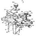
- FIG. 1is a perspective view of a first embodiment of a surgical retractor of the present invention.
- FIG. 2is a view of the embodiment of FIG. 1 drawn to show internal parts of the embodiment.
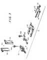
- FIG. 3is an exploded view of the embodiment of FIG. 1 .
- FIG. 4is a view of a thread assembly of the embodiment of FIG. 1 .
- FIG. 5is a perspective view of a rack assembly of the embodiment of FIG. 1 .
- FIG. 6is a perspective view of a swivel assembly of the embodiment of FIG. 1 .
- FIG. 7is a perspective view of the blade assembly, comprising a first and second blade, of the embodiment of FIG. 1 .
- FIG. 8is a schematic view of the blade assembly, comprising a first and second blade, of the embodiment of FIG. 1 .
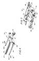
- FIG. 9is a perspective view of a second embodiment of a surgical retractor of the present invention.
- FIG. 10is an exploded view of the embodiment of FIG. 9 .
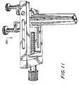
- FIG. 11is a copy of a photograph of a first view of a surgical retractor of the present invention in a closed position.
- FIG. 12is a copy of a photograph of a second view of the surgical retractor of FIG. 11 in the closed position.
- FIG. 13is a copy of a photograph of the surgical retractor of FIG. 11 being opened.
- FIG. 14is a copy of a photograph of the surgical retractor of FIG. 11 in an open position with first and second blades substantially parallel.
- FIG. 15is a copy of a photograph of the surgical retractor of FIG. 11 in an open position with the first blade at an acute angle and the second blade at a different angle from that of the first blade.
- FIG. 16is a copy of a photograph of the surgical retractor of FIG. 11 in an open position with both blades angled outwardly to form a reverse funnel.
- FIG. 17shows a front view of a side blade of the present invention.
- FIG. 18shows a side view of a side blade of the present invention.
- FIG. 19is a perspective view of the swivel assembly of FIG. 6 modified to include thumbscrews to further hold blades in place.
- FIG. 20is a perspective view of a hand held retractor that may be used with the retractor of the present invention.
- FIG. 1shows a first embodiment of the assembled surgical retractor 10 of the present invention.
- the surgical retractor 10has a number of parts designed to fit together to provide smooth and efficient operation in the surgery room.
- the surgical retractor 10comprises a thread assembly 20 , a rack assembly 50 , a swivel assembly 70 , and removable blade assembly 90 .
- the rack assembly 50is a U-shaped rack having a first leg 52 , a second leg 54 and a rack crosspiece 58 .
- the first leg 52 and second leg 54extend from respective ends of the rack crosspiece 58 .
- Each leg 52 , 54defines a respective elongate transverse slot 64 having open sides.
- the rack crosspiece 58defines first and second receiving holes 66 aligned with the longitudinal axis of, and in communication with, one of the transverse slots 64 .
- the rack assembly 50also has openings 60 and a substantially planer platform 56 extending from the second leg 54 .
- the rack crosspiece 58also defines a threaded receiving opening 59 , discussed in more detail below.
- the U-shaped thread assembly 20slidably engages the rack assembly 50 .
- the U-shaped thread assembly 20comprises a thread assembly crosspiece 28 having traveler rods 24 attached at or adjacent to opposed ends of the thread assembly crosspiece 28 .
- a threaded rod 22is rotatably attached to a midpoint of the thread assembly crosspiece 28 .
- the threaded rod 22is substantially parallel to the traveler rods 24 and is located between the traveler rods 24 .
- the threaded rod 22has a first end 23 and a second end 25 .
- Second end 25passes through an opening 27 through the crosspiece 28 and interlocks with a knob 30 .
- Knob 30is a knurled knob rod to permit easy gripping for turning by the surgeon.
- the end 25 and knob 30interlock so that turning knob 30 directly turns the threaded rod 22 to adjust the spacing between a proximal end 94 of first blade 91 and a proximal end 95 of second blade 92 .
- proximal end 94is proximal to a first blade mount 82 of the swivel assembly 70 .
- Proximal end 95is proximal to a second blade mount 84 of the swivel assembly 70 .
- the blades 91 , 92also have distal ends 96 , 97 , which are distal to respective blade mounts 82 , 84 .
- the blades 91 , 92are typically inserted into the respective blade mounts 82 , 84 when the blade mounts 82 , 84 are together such that the retractor 10 is in a closed position.
- FIG. 19shows an embodiment employing such an element.
- thumbscrews 400are provided to pass through threaded holes 410 of blade mounts 482 , 484 to contact the respective blades 91 , 92 and assist in holding the blades 91 , 92 in place.
- Mounts 482 , 484otherwise are employed and configured as are mounts 82 , 84 .
- the threaded rod 22is slidably connected to the rack assembly 50 by the threaded receiving opening 59 at the rack crosspiece 58 .
- Each traveler rod 24is slidably connected to a respective one of the legs 52 , 54 of the rack assembly 50 by passing through a respective one of the receiving openings 66 into a respective one of the slots 64 .
- the traveler rods 24are attached within the legs 52 , 54 by pins 26 which respectively pass through the slots 64 and attach to respective traveler rods 24 at rod side openings 26 a.
- the blade assembly 90comprises first blade 91 and second blade 92 .
- the blades 91 , 92have respective proximal ends 94 , 95 , distal ends 96 , 97 and opposed sidewalls 98 , 99 .
- the blades 90 , 91are typically also provided with a conduit 100 for holding a fiberoptic cable (FIG. 7 shows one of the conduits 100 ).
- the blades 91 , 92are interchangeable, that is, they may be easily removed from the retractor 10 to be exchanged for other blades of differing compositions or lengths. In use, the blades 91 , 92 may be of the same or different lengths. Lengths of the first and second blades 91 , 92 are indicated on FIG. 8 by lengths L 1 , L 2 , respectively.
- the blades 91 , 92are made of a disposable material such as a sturdy surgically acceptable polymer.
- suitable polymersare thermoplastic or thermoset resins such as polyvinylchloride, acetal resin (e.g., DELRIN available from DuPont), polyurethane, polystyrene, polycarbonate, polyacrylate, polyethylene, or polypropylene.
- the polymersmay be reinforced with conventional reinforcing agents such as natural or synthetic fibers, e.g., nylon, or carbon black.
- FIG. 6shows the swivel assembly 70 in detail.
- Swivel assembly 70comprises a first swivel 72 having the first blade mount 82 rotatably connected to the U-shaped rack assembly 50 opposite the rack crosspiece 58 .
- the swivel assembly 70also comprises a second swivel 74 having a second blade mount 84 rotatably attached to the ends of the traveler rods 24 opposite the thread assembly crosspiece 28 .
- the first swivel 72comprises a first swivel arm 88 , having a threaded hole 78 A for passing a threaded thumbscrew 76 A therethrough. An end of the threaded screw 76 A contacts a surface of platform 56 extending from second leg 54 .
- the second swivel 74comprises a second swivel arm 89 , having a threaded hole 78 B for passing a threaded thumbscrew 76 B therethrough. An end of the threaded screw 76 B contacts the surface of platform 56 extending from second leg 54 .
- the thumbscrew 76 A of the first swivel assembly 72would contact a different leg or extension of leg than would the thumbscrew 76 B of the second swivel assembly 74 .
- the heads of the thumbscrews 76 A, 76 Bare large enough, and have a suitably grippable surface, for easy turning by a surgeon.
- the thumbscrews 76 A, 76 Btypically have a diameter of about 1 ⁇ 2 inch and a knurled surface.
- the thumbscrews 76 A, 76 Bare preferably plastic.
- Prongs 80(FIG. 6) of opposed sides of the first blade mount 82 are inserted into openings 60 (FIG. 5) of the rack assembly 50 to rotatably attach the first swivel 72 to the rack assembly 50 . End 23 of the threaded rod 22 pushes against the second blade mount 84 .
- the swivel assembly 70swivels to permit adjustment of the angle of the blades 91 , 92 relative to the rack assembly 50 or thread assembly 20 to which the respective blade mounts 82 , 84 are rotatably mounted.
- the adjustment of the angle of the blades 91 , 92permits the blades to fan out within the patient's body such that the blade distal ends 96 , 97 are further apart from each other than are the blade proximal ends 94 , 95 .
- This angle adjustmentis easily accomplished by turning the thumbscrews 76 A, 76 B to protrude from the respective swivel arm 88 , 89 , the appropriate distance to force the blades 91 , 92 to take the desired angle.
- Lower ends of the thumbscrews 76 A, 76 Bafter sufficient turning, push against the platform 56 to cause the blades 91 , 92 to be held at the appropriate angle.
- the bladesare 23 ⁇ 8 to 21 ⁇ 2 inches wide and 1 to 6 inches long. Generally, the blades are 4 to 5 inches long. As stated above, the blades are interchangeable and preferably made of plastic to be disposable.
- the blade proximal ends 94 , 95can move from a closed position wherein the blades are about 0 inches apart to an open position (see FIG. 8) wherein the blades are substantially parallel and a distance “A” of about 2-4 inches, preferably about 2-3 inches, apart.
- the distal ends 96 , 97may be each moved an additional 0 to about 4 inches apart.
- a total internal operating window “D”of as much as about 11 inches may be achieved. If desired only one blade 91 or 92 has its angle adjusted to achieve spans “B” or “C” of up to about 7 inches.
- the surgical retractor 10 of the present inventionwould be employed as follows.
- the surgeonwould make an incision into the patient at the appropriate location for the particular surgery. This typically involves an incision about 3 to about 5 inches long.
- the blades 91 , 92 of the retractor 10would be inserted through the incision while being in a closed position during which the blades 91 , 92 are substantially adjacent. Generally, the blades 91 , 92 are initially parallel to each other in the closed position. Then, the knob 30 is turned counterclockwise to pull the entire thread assembly 20 , second blade mount 84 , and second swivel 74 (which is attached to the thread assembly 20 ), away from the first blade mount 82 .
- proximal end 95 of second blade 92moves away from the proximal end 94 of the first blade 91 a sufficient distance, e.g., about 2.5 to about 4 inches, for the surgeon to perform the surgery.
- the distanceis sufficient to insert and operate surgical instruments and permit the surgeon to view internal organs and to palpate internal organs with one or two fingers.
- distal ends 96 , 97may be further moved apart by independently moving either or both blades 91 , 92 to an angle X, Y (see FIG. 8) of between 0° and about 45° away from normal (90°) relative to the respective rack assembly 50 and thread assembly 20 .
- the angle of one or both blades 91 , 92 relative to the rack assembly 50 and thread assembly 20 , respectively,is adjusted by appropriately turning the thumbscrews 76 A, 76 B.
- thumbscrew 76 Ais turned clockwise to put a greater portion of thumbscrew 76 A between the first swivel arm 88 and the platform 56 . This causes the first swivel 72 , first blade mount 82 and first blade 91 to tilt to an angle to move distal end 96 away from distal end 97 .
- the thumbscrew 76 Bis turned clockwise to put a relatively greater portion of thumbscrew 76 B between the second swivel arm 89 and the platform 56 . This causes the second swivel 74 , second blade mount 84 , and the second blade 92 to tilt to an angle Y to move distal end 97 away from distal end 96 .
- a surgeoncan achieve an operating window within the patient which is up to 8 inches larger than the operating window at the surface of the patient's skin because each of the distal ends 96 , 97 can move outwardly away from each other a distance of as much as about 4 inches.
- Thismakes possible a wide variety of surgeries with only a minimal incision.
- the incisionis wide enough that many surgical instruments which are similar to, or the same as, those used in conventional surgeries may be employed for such an operation.
- the surgeoncan put one or two fingers into the incision to actually touch the internal organs being operated on.
- the incisionpermits the surgeon to see the organs being operated on.
- excellent lighting provided by the fiberoptics or other acceptable internal surgical lightinggives the surgeon an excellent view of the internal operating area.
- a surgeoncan also conveniently pass an endoscope into the incision to magnify views inside the patients body as desired.
- FIGS. 9 and 10show a second embodiment of a surgical retractor 110 of the present invention.
- surgical retractor 110has two inner thumbscrews 177 A, 177 B.
- the presence of four thumbscrewspermits the blades 92 , 92 to tilt outwardly or inwardly.
- the angle X of the blade 91 relative to the rack assembly 50 , and angle Y of the blade 92 relative to the thread assembly 20are adjusted by appropriately turning the thumbscrews 76 A, 76 B, 177 A, 177 B.
- inner thumbscrew 177 Ais turned counterclockwise away from platform 56 .
- thumbscrew 76 Ais turned clockwise to put a greater portion of the thumbscrew 76 A between the first platform 56 and swivel arm 188 relative to the portion of the inner thumbscrew 177 A between the swivel arm 188 and the platform 56 .
- Thiscauses the first swivel 172 , first blade mount 182 and first blade 91 to tilt to an angle to move distal end 96 away from distal end 97 .
- inner thumbscrew 177 Bis turned counterclockwise away from platform 56 . Then thumbscrew 76 B is turned clockwise to put a greater portion of thumbscrew 76 B between the platform 56 and second swivel arm 189 relative to the portion of the inner thumbscrew 177 B between the second swivel arm 189 and the platform 56 . This causes the second swivel 174 , second blade mount 182 and second blade 92 to tilt to an angle to move second distal end 97 away from first distal end 96 .
- FIGS. 11-16show an actually made embodiment of the surgical retractor of the present invention. All the parts shown in white of the surgical retractor of FIGS. 11-16 are plastic. As can be seen in FIGS. 11-16, a few parts, e.g., traveling rods, screws attaching the traveling rods to the thread assembly crosspiece, pins for attaching the travelling rods to the transverse slots of the rack assembly, and a screw adjacent the knob of the thread assembly are shown to be made of metal.
- traveling rodse.g., traveling rods, screws attaching the traveling rods to the thread assembly crosspiece, pins for attaching the travelling rods to the transverse slots of the rack assembly, and a screw adjacent the knob of the thread assembly are shown to be made of metal.
- FIG. 11is a copy of a photograph of a first view of a surgical retractor 210 of the present invention in a closed position.
- FIG. 12is a copy of a photograph of a second view of the surgical retractor 210 of FIG. 11 in the closed position.
- FIG. 13is a copy of a photograph of the surgical retractor 210 of FIG. 11 being opened.
- FIG. 14is a copy of a photograph of the surgical retractor 210 of FIG. 11 in an open position with first and second blades substantially parallel.
- FIG. 15is a copy of a photograph of the surgical retractor 210 of FIG. 11 in an open position with the first blade at a first angle and the second blade at a second angle which is different from that of the first blade.
- FIG. 16is a copy of a photograph of the surgical retractor 210 of FIG. 11 of the surgical retractor of FIG. 11 in an open position with both blades angled outwardly to form a reverse funnel.
- FIGS. 17 and 18show front and side views, respectively, of an embodiment of such a side blade 300 .
- the side blade 300has a wall 302 having an inner surface 304 and an outer surface 306 .
- the side blade 300also has an extension 308 integral with the wall 302 and a lip 310 integral with the extension 308 .
- the wall 302 , extension 308 and lip 310form a U-shaped channel which snugly fits over a leg of a retractor, for example, either first leg 52 or second leg 54 of the embodiment of FIG. 5 .
- the side blade 300holds itself sufficiently tightly to the leg to hold back tissue in the operating field.
- the side blade 300prevents caving of body organs into the operating field. This is particularly advantageous when the blades 91 , 92 (FIG. 1) are positioned to have their distal ends 96 , 97 (FIG. 7) a large distance apart, such as 9-11 inches apart.
- both first leg 52 and second leg 54may have their own respective side blade 300 .
- the side blades 300may be used at any stage of surgery wherein the blade mounts 82 , 84 are sufficiently apart for the side blade 300 to be inserted on a leg 52 , 54 between the blade mounts 82 , 84 .
- the side blade 300typically has a thickness “T” of about 0.1 to about 0.3 inches, a length “L 3 ” of about 1 to about 6 inches, a width “W” of about 0.75 to about 2 inches, a depth “D 1 ” of about 0.75 to about 1.5 inches and its lip 310 has a length “L 4 ” of about 0.5 to about 1 inch.
- a typical side blade 300is about 0.16 inches thick, about 5 inches long, about 1.25 inch wide, between 0.9 and 1 inch deep and has a lip length of about 0.8 inch.
- the side blades 300are interchangeable and preferably made of surgically acceptable polymer to be disposable. Typical suitable polymers are listed above with respect to blades 91 , 92 .
- the polymersmay be reinforced with conventional reinforcing agents such as natural or synthetic fibers, e.g., nylon, or carbon black.
- the side blade 300may further include a thumbscrew, not shown but similar to thumbscrew 400 (FIG. 19 ), to pass through a hole (not shown) in an upper part of the wall 302 to contact the leg 52 or 54 to further hold the side blade 300 in place.
- a thumbscrewnot shown but similar to thumbscrew 400 (FIG. 19 ) to pass through a hole (not shown) in an upper part of the wall 302 to contact the leg 52 or 54 to further hold the side blade 300 in place.
- the side blade 300may also be provided with a light source 320 to illuminate the operating field.
- Typical Light sourcesemploy fiber optics.
- a preferred light sourceis a lightpipe having a thin lighted panel available from LUMITEX, Inc., Strongsville, Ohio. These LUMITEX panels comprise woven optical fibers. The light is emitted from the sides of the fibers through the claddings. Thus, light is provided across the panel surface. Further information regarding the lightpipes available from LUMITEX, Inc. are provided by U.S. Pat. Nos. 5,005,108, 5,618,096 and 5,613,753 incorporated herein by reference. The panels are molded into the side blade 300 or attached to the side blade 300 .
- the light source 320is a panel of a LUMITEX lightpipe molded into the side blade 300 .
- Lightis provided through a cable 330 which passes through the wall 302 to the panel.
- a panel of LUMITEX lightpipeis attached to the side blade 300 and the cable for providing light to the panel runs over the outer surface 306 of the side blade 300 .
- a LUMITEX lightpipe panelmay be molded or attached to blades 91 , 92 (not shown).
- a hand held retractor 500such as that of FIG. 20, may be employed instead of employing the side blade 300 (or one leg may have a hand held retractor and the other leg may have a side blade).
- Hand held retractor 500has a handle 510 integral with a blade 520 .
- the hand held retractor 500is disposable and made of plastic.
- the hand held retractor 500may also have light source 320 supplied with light cable 330 molded into the retractor 500 (FIG. 20) or attached to the retractor 500 (not shown).
Landscapes
- Health & Medical Sciences (AREA)
- Life Sciences & Earth Sciences (AREA)
- Surgery (AREA)
- Nuclear Medicine, Radiotherapy & Molecular Imaging (AREA)
- Molecular Biology (AREA)
- Veterinary Medicine (AREA)
- Public Health (AREA)
- General Health & Medical Sciences (AREA)
- Animal Behavior & Ethology (AREA)
- Engineering & Computer Science (AREA)
- Biomedical Technology (AREA)
- Heart & Thoracic Surgery (AREA)
- Medical Informatics (AREA)
- Physics & Mathematics (AREA)
- Biophysics (AREA)
- Radiology & Medical Imaging (AREA)
- Pathology (AREA)
- Optics & Photonics (AREA)
- Surgical Instruments (AREA)
Abstract
Description
This application claims priority from U.S. Provisional Patent Application No. 60/093,992, filed Jul. 24, 1998.
1. Field of the Invention
The present invention relates to a surgical retractor for permitting a wide variety of surgeries through an operating window. More particularly, the retractor permits surgery through a small outer incision, i.e., outer operating window, while providing a field of operation within the patient's body, i.e., inner operating window, which is larger than the outer operating window.
2. Background Discussion
In many types of surgery it is necessary to make an incision in a patient through the patient's skin and underlying tissues to permit operating on internal organs, etc. of that patient. Thus the incision creates an opening through the epidermis, dermis, subcutaneous tissue (including fat cells), fascia (covering muscle), and muscle. In some cases, e.g., coronary by-pass, the incision must also cut through hard body tissue, i.e., sternum. A retractor is often needed to keep the tissues at either side of the incision sufficiently apart to keep open an operating window through which the surgery is performed. For example, sternal retractors are necessary instruments for performing coronary bypass surgery. See for example, U.S. Pat. No. 4,852,552 to Chaux, incorporated herein by reference. Retractors generally keep the operating window open by pushing the two opposed sides of the incision away from each other. Some retractors for endoscopic surgery are also provided with a fiberoptic mechanism to light the operating area. A retractor with a fiberoptic mechanism is disclosed by U.S. Pat. No. 5,503,617 to Jako. U.S. Pat. No. 5,503,617 to Jako asserts that its retractor has lower and upper blades wherein the angle of the lower blade relative to its lower blade mount and the angle of the upper blade relative to its upper blade mount can be adjusted independently. However, this device is somewhat complex.
Although a wide variety of surgical retractors are known, it would be advantageous to provide a surgical retractor which is easier to use than those commercially available, highly reliable, disposable, and more economical. It would also be advantageous to provide a surgical retractor which economically permits an internal operating window area which is larger than its external operating window.
It is an object of the present invention to provide a surgical retractor which, in a easy to use economical fashion, provides for an internal operating window of much greater area than an external operating window.
It is another object of the present invention to provide a method of surgery employing the surgical retractor of the present invention.
The apparatus of the present invention is a surgical retractor comprising a U-shaped rack having a first leg, a second leg and a rack crosspiece. The first leg and second leg extend from respective ends of the rack crosspiece and each leg defines a respective transverse slot having open sides. The rack crosspiece defines first and second receiving holes respectively longitudinally aligned with, and in communication with, one of the transverse slots. The surgical retractor also comprises a U-shaped thread assembly comprising a thread assembly crosspiece having traveler rods attached at or adjacent to opposed ends of the thread assembly crosspiece. A threaded rod is rotatably attached to the thread assembly crosspiece, the threaded rod being substantially parallel to the traveler rods and located between the traveler rods. The threaded rod has opposed first and second ends and is connected to the rack by a threaded receiving opening at the rack crosspiece. Each of the traveler rods is slidably connected to a respective one of the legs of the rack assembly by passing through a respective one of the receiving openings into a respective one of the slots.
A first blade and a second blade are also included. The first blade has a sidewall opposed to a sidewall of the second blade. A swivel assembly comprising a first swivel having a first blade mount is rotatably connected to the U-shaped rack opposite the rack crosspiece. A second swivel having a second blade mount is rotatably attached to the ends of the travelers opposite the thread assembly crosspiece. The first swivel comprises a first swivel arm having at least one threaded hole for passing at least one respective threaded screw therethrough. The at least one threaded screw of the first swivel contacts a surface of one of the legs of the rack to adjust an angle of the first blade relative to the legs of the rack. The second swivel has a second arm having at least one threaded hole for passing at least one respective threaded screw therethrough. The at least one threaded screw of the second swivel contacts a surface of the rack to adjust an angle of the second blade relative to the legs of the rack. The blades have respective proximal ends and distal ends. The proximal ends are attached to the respective blade mounts. The distal ends are distal to the blade mounts. By the unique, yet simple, structure of the present invention, the position of the blades is adjustable such that the blade distal ends can be further apart from each other than are the blade proximal ends. This achieves an internal operating window having an area larger than that of its external operating window.
The device may be made entirely of stainless steel or titanium. However, typically at least the blades are made of plastic such as polyurethane, polystyrene, polycarbonate, polyacrylate, polyethylene, or polypropylene. The polymers may be reinforced with conventional reinforcing agents such as natural or synthetic fibers, e.g., nylon, or carbon black. Preferably, the majority of the parts of the apparatus of the present invention are made of plastic to facilitate using the present retractor as a disposable retractor. Thus, preferably, parts such as the U-shaped racks, U-shaped thread assembly crosspiece, first swivel, second swivel and blades are made of plastic.
A disposable retractor is advantageous to minimize risks of transmitting infection from one surgical patient to another and ensures that a new reliable device is used for every surgery.
The following briefly describes the drawings in which like elements are labeled by like numbers.
FIG. 1 is a perspective view of a first embodiment of a surgical retractor of the present invention.
FIG. 2 is a view of the embodiment of FIG. 1 drawn to show internal parts of the embodiment.
FIG. 3 is an exploded view of the embodiment of FIG.1.
FIG. 4 is a view of a thread assembly of the embodiment of FIG.1.
FIG. 5 is a perspective view of a rack assembly of the embodiment of FIG.1.
FIG. 6 is a perspective view of a swivel assembly of the embodiment of FIG.1.
FIG. 7 is a perspective view of the blade assembly, comprising a first and second blade, of the embodiment of FIG.1.
FIG. 8 is a schematic view of the blade assembly, comprising a first and second blade, of the embodiment of FIG.1.
FIG. 9 is a perspective view of a second embodiment of a surgical retractor of the present invention.
FIG. 10 is an exploded view of the embodiment of FIG.9.
FIG. 11 is a copy of a photograph of a first view of a surgical retractor of the present invention in a closed position.
FIG. 12 is a copy of a photograph of a second view of the surgical retractor of FIG. 11 in the closed position.
FIG. 13 is a copy of a photograph of the surgical retractor of FIG. 11 being opened.
FIG. 14 is a copy of a photograph of the surgical retractor of FIG. 11 in an open position with first and second blades substantially parallel.
FIG. 15 is a copy of a photograph of the surgical retractor of FIG. 11 in an open position with the first blade at an acute angle and the second blade at a different angle from that of the first blade.
FIG. 16 is a copy of a photograph of the surgical retractor of FIG. 11 in an open position with both blades angled outwardly to form a reverse funnel.
FIG. 17 shows a front view of a side blade of the present invention.
FIG. 18 shows a side view of a side blade of the present invention.
FIG. 19 is a perspective view of the swivel assembly of FIG. 6 modified to include thumbscrews to further hold blades in place.
FIG. 20 is a perspective view of a hand held retractor that may be used with the retractor of the present invention.
FIG. 1 shows a first embodiment of the assembledsurgical retractor 10 of the present invention. As shown in FIG. 3, thesurgical retractor 10 has a number of parts designed to fit together to provide smooth and efficient operation in the surgery room. Thesurgical retractor 10 comprises athread assembly 20, arack assembly 50, aswivel assembly 70, andremovable blade assembly 90.
As shown in FIG. 5, therack assembly 50 is a U-shaped rack having afirst leg 52, asecond leg 54 and arack crosspiece 58. Thefirst leg 52 andsecond leg 54 extend from respective ends of therack crosspiece 58. Eachleg transverse slot 64 having open sides. Therack crosspiece 58 defines first and second receiving holes66 aligned with the longitudinal axis of, and in communication with, one of thetransverse slots 64. Therack assembly 50 also hasopenings 60 and a substantiallyplaner platform 56 extending from thesecond leg 54. Therack crosspiece 58 also defines a threaded receivingopening 59, discussed in more detail below.
As shown by FIG. 1, theU-shaped thread assembly 20 slidably engages therack assembly 50. As shown by FIG. 4, theU-shaped thread assembly 20 comprises athread assembly crosspiece 28 havingtraveler rods 24 attached at or adjacent to opposed ends of thethread assembly crosspiece 28. A threadedrod 22 is rotatably attached to a midpoint of thethread assembly crosspiece 28. The threadedrod 22 is substantially parallel to thetraveler rods 24 and is located between thetraveler rods 24.
The threadedrod 22 has afirst end 23 and asecond end 25.Second end 25 passes through anopening 27 through thecrosspiece 28 and interlocks with aknob 30.Knob 30 is a knurled knob rod to permit easy gripping for turning by the surgeon. Thus, theend 25 andknob 30 interlock so that turningknob 30 directly turns the threadedrod 22 to adjust the spacing between aproximal end 94 offirst blade 91 and aproximal end 95 ofsecond blade 92. As defined in this specification,proximal end 94 is proximal to afirst blade mount 82 of theswivel assembly 70.Proximal end 95 is proximal to asecond blade mount 84 of theswivel assembly 70. Theblades distal ends
Theblades retractor 10 is in a closed position.
An element that is moved in place to overhang or otherwise contact the proximal ends94,95, respectively, may be provided. This element assists in holding theblades blades thumbscrews 400 are provided to pass through threadedholes 410 of blade mounts482,484 to contact therespective blades blades Mounts mounts
The threadedrod 22 is slidably connected to therack assembly 50 by the threaded receivingopening 59 at therack crosspiece 58. Eachtraveler rod 24 is slidably connected to a respective one of thelegs rack assembly 50 by passing through a respective one of the receivingopenings 66 into a respective one of theslots 64. As shown by FIGS. 1,4 and5, thetraveler rods 24 are attached within thelegs pins 26 which respectively pass through theslots 64 and attach torespective traveler rods 24 at rod side openings26a.
As shown by FIG. 7, theblade assembly 90 comprisesfirst blade 91 andsecond blade 92. Theblades opposed sidewalls 98,99. Theblades conduit 100 for holding a fiberoptic cable (FIG. 7 shows one of the conduits100). Theblades retractor 10 to be exchanged for other blades of differing compositions or lengths. In use, theblades second blades
Preferably, theblades
FIG. 6 shows theswivel assembly 70 in detail.Swivel assembly 70 comprises afirst swivel 72 having thefirst blade mount 82 rotatably connected to theU-shaped rack assembly 50 opposite therack crosspiece 58. Theswivel assembly 70 also comprises asecond swivel 74 having asecond blade mount 84 rotatably attached to the ends of thetraveler rods 24 opposite thethread assembly crosspiece 28.
Thefirst swivel 72 comprises afirst swivel arm 88, having a threadedhole 78A for passing a threadedthumbscrew 76A therethrough. An end of the threadedscrew 76A contacts a surface ofplatform 56 extending fromsecond leg 54. Thesecond swivel 74 comprises asecond swivel arm 89, having a threadedhole 78B for passing a threadedthumbscrew 76B therethrough. An end of the threadedscrew 76B contacts the surface ofplatform 56 extending fromsecond leg 54. In other embodiments, not shown, it is conceivable that thethumbscrew 76A of thefirst swivel assembly 72 would contact a different leg or extension of leg than would thethumbscrew 76B of thesecond swivel assembly 74. The heads of the thumbscrews76A,76B are large enough, and have a suitably grippable surface, for easy turning by a surgeon. Thus, thethumbscrews thumbscrews
Prongs80 (FIG. 6) of opposed sides of thefirst blade mount 82 are inserted into openings60 (FIG. 5) of therack assembly 50 to rotatably attach thefirst swivel 72 to therack assembly 50.End 23 of the threadedrod 22 pushes against thesecond blade mount 84.
Theswivel assembly 70 swivels to permit adjustment of the angle of theblades rack assembly 50 orthread assembly 20 to which the respective blade mounts82,84 are rotatably mounted.
The adjustment of the angle of theblades thumbscrews respective swivel arm blades platform 56 to cause theblades
Typically, the blades are 2⅜ to 2½ inches wide and 1 to 6 inches long. Generally, the blades are 4 to 5 inches long. As stated above, the blades are interchangeable and preferably made of plastic to be disposable. The blade proximal ends94,95 can move from a closed position wherein the blades are about 0 inches apart to an open position (see FIG. 8) wherein the blades are substantially parallel and a distance “A” of about 2-4 inches, preferably about 2-3 inches, apart. By adjusting the angles X,Y ofblades 91,92 (see FIG.8), the distal ends96,97 may be each moved an additional 0 to about 4 inches apart. Thus, a total internal operating window “D” of as much as about 11 inches may be achieved. If desired only oneblade
In a typical surgery, thesurgical retractor 10 of the present invention would be employed as follows.
First, the surgeon would make an incision into the patient at the appropriate location for the particular surgery. This typically involves an incision about 3 to about 5 inches long. Theblades retractor 10 would be inserted through the incision while being in a closed position during which theblades blades knob 30 is turned counterclockwise to pull theentire thread assembly 20,second blade mount 84, and second swivel74 (which is attached to the thread assembly20), away from thefirst blade mount 82. This forces theproximal end 95 ofsecond blade 92 to move away from theproximal end 94 of the first blade91 a sufficient distance, e.g., about 2.5 to about 4 inches, for the surgeon to perform the surgery. Typically the distance is sufficient to insert and operate surgical instruments and permit the surgeon to view internal organs and to palpate internal organs with one or two fingers.
Then the distal ends96,97 may be further moved apart by independently moving either or bothblades respective rack assembly 50 andthread assembly 20.
The angle of one or bothblades rack assembly 50 andthread assembly 20, respectively, is adjusted by appropriately turning thethumbscrews
In particular, to adjust the angle of thefirst blade 91,thumbscrew 76A is turned clockwise to put a greater portion ofthumbscrew 76A between thefirst swivel arm 88 and theplatform 56. This causes thefirst swivel 72,first blade mount 82 andfirst blade 91 to tilt to an angle to movedistal end 96 away fromdistal end 97.
To adjust the angle “X” of thesecond blade 92, thethumbscrew 76B is turned clockwise to put a relatively greater portion ofthumbscrew 76B between thesecond swivel arm 89 and theplatform 56. This causes thesecond swivel 74,second blade mount 84, and thesecond blade 92 to tilt to an angle Y to movedistal end 97 away fromdistal end 96.
Thus, by simply turning thethumbscrews
FIGS. 9 and 10 show a second embodiment of asurgical retractor 110 of the present invention. The difference between the first and second embodiments is thatsurgical retractor 110 has twoinner thumbscrews blades
For the second embodiment, the angle X of theblade 91 relative to therack assembly 50, and angle Y of theblade 92 relative to thethread assembly 20, are adjusted by appropriately turning thethumbscrews
In particular, to outwardly adjust the angle X of thefirst blade 91,inner thumbscrew 177A is turned counterclockwise away fromplatform 56. Then thumbscrew76A is turned clockwise to put a greater portion of thethumbscrew 76A between thefirst platform 56 andswivel arm 188 relative to the portion of theinner thumbscrew 177A between theswivel arm 188 and theplatform 56. This causes thefirst swivel 172,first blade mount 182 andfirst blade 91 to tilt to an angle to movedistal end 96 away fromdistal end 97.
To outwardly adjust the angle Y of thesecond blade 92,inner thumbscrew 177B is turned counterclockwise away fromplatform 56. Then thumbscrew76B is turned clockwise to put a greater portion ofthumbscrew 76B between theplatform 56 andsecond swivel arm 189 relative to the portion of theinner thumbscrew 177B between thesecond swivel arm 189 and theplatform 56. This causes thesecond swivel 174,second blade mount 182 andsecond blade 92 to tilt to an angle to move seconddistal end 97 away from firstdistal end 96.
To inwardly adjust the blade angles, the steps for turning thethumbscrews respective swivel arms screws
FIGS. 11-16 show an actually made embodiment of the surgical retractor of the present invention. All the parts shown in white of the surgical retractor of FIGS. 11-16 are plastic. As can be seen in FIGS. 11-16, a few parts, e.g., traveling rods, screws attaching the traveling rods to the thread assembly crosspiece, pins for attaching the travelling rods to the transverse slots of the rack assembly, and a screw adjacent the knob of the thread assembly are shown to be made of metal.
FIG. 11 is a copy of a photograph of a first view of asurgical retractor 210 of the present invention in a closed position.
FIG. 12 is a copy of a photograph of a second view of thesurgical retractor 210 of FIG. 11 in the closed position.
FIG. 13 is a copy of a photograph of thesurgical retractor 210 of FIG. 11 being opened.
FIG. 14 is a copy of a photograph of thesurgical retractor 210 of FIG. 11 in an open position with first and second blades substantially parallel.
FIG. 15 is a copy of a photograph of thesurgical retractor 210 of FIG. 11 in an open position with the first blade at a first angle and the second blade at a second angle which is different from that of the first blade.
FIG. 16 is a copy of a photograph of thesurgical retractor 210 of FIG. 11 of the surgical retractor of FIG. 11 in an open position with both blades angled outwardly to form a reverse funnel.
It is also advantageous to provide the retractors of the present invention with auxiliary side blades. FIGS. 17 and 18 show front and side views, respectively, of an embodiment of such aside blade 300. Theside blade 300 has awall 302 having aninner surface 304 and anouter surface 306. Theside blade 300 also has anextension 308 integral with thewall 302 and alip 310 integral with theextension 308.
Thewall 302,extension 308 andlip 310 form a U-shaped channel which snugly fits over a leg of a retractor, for example, eitherfirst leg 52 orsecond leg 54 of the embodiment of FIG.5. Thus, theside blade 300 holds itself sufficiently tightly to the leg to hold back tissue in the operating field. Thus, theside blade 300 prevents caving of body organs into the operating field. This is particularly advantageous when theblades 91,92 (FIG. 1) are positioned to have theirdistal ends 96,97 (FIG. 7) a large distance apart, such as 9-11 inches apart. Of course, bothfirst leg 52 andsecond leg 54 may have their ownrespective side blade 300. While especially advantageous when the blade distal ends96,97 are far apart, theside blades 300 may be used at any stage of surgery wherein the blade mounts82,84 are sufficiently apart for theside blade 300 to be inserted on aleg
Theside blade 300 typically has a thickness “T” of about 0.1 to about 0.3 inches, a length “L3” of about 1 to about 6 inches, a width “W” of about 0.75 to about 2 inches, a depth “D1” of about 0.75 to about 1.5 inches and itslip 310 has a length “L4” of about 0.5 to about 1 inch. Atypical side blade 300 is about 0.16 inches thick, about 5 inches long, about 1.25 inch wide, between 0.9 and 1 inch deep and has a lip length of about 0.8 inch. Theside blades 300 are interchangeable and preferably made of surgically acceptable polymer to be disposable. Typical suitable polymers are listed above with respect toblades
Theside blade 300, if desired, may further include a thumbscrew, not shown but similar to thumbscrew400 (FIG.19), to pass through a hole (not shown) in an upper part of thewall 302 to contact theleg side blade 300 in place.
Theside blade 300 may also be provided with alight source 320 to illuminate the operating field. Typical Light sources employ fiber optics. A preferred light source is a lightpipe having a thin lighted panel available from LUMITEX, Inc., Strongsville, Ohio. These LUMITEX panels comprise woven optical fibers. The light is emitted from the sides of the fibers through the claddings. Thus, light is provided across the panel surface. Further information regarding the lightpipes available from LUMITEX, Inc. are provided by U.S. Pat. Nos. 5,005,108, 5,618,096 and 5,613,753 incorporated herein by reference. The panels are molded into theside blade 300 or attached to theside blade 300.
In the embodiment of FIG. 17, thelight source 320 is a panel of a LUMITEX lightpipe molded into theside blade 300. Light is provided through acable 330 which passes through thewall 302 to the panel. In an alternative, not shown, a panel of LUMITEX lightpipe is attached to theside blade 300 and the cable for providing light to the panel runs over theouter surface 306 of theside blade 300.
Likewise, if desired, a LUMITEX lightpipe panel may be molded or attached toblades 91,92 (not shown).
If desired a hand heldretractor 500, such as that of FIG. 20, may be employed instead of employing the side blade300 (or one leg may have a hand held retractor and the other leg may have a side blade). Hand heldretractor 500 has ahandle 510 integral with ablade 520. Preferably, the hand heldretractor 500 is disposable and made of plastic. The hand heldretractor 500 may also havelight source 320 supplied withlight cable 330 molded into the retractor500 (FIG. 20) or attached to the retractor500 (not shown).
It should be appreciated that many embodiments other than those specifically described above come within the spirit and scope of the present invention. Thus, the present invention is not defined by the above description, but rather, is defined by the claims appended hereto.
Claims (17)
1. A surgical retractor apparatus comprising:
a U-shaped rack having a first leg, a second leg and a rack crosspiece, wherein the first leg and second leg extend from respective ends of the rack crosspiece, each leg defining a respective transverse slot having open sides, the rack crosspiece defining first and second receiving holes respectively aligned with a longitudinal axis of, and in communication with, one of said transverse slots, the rack crosspiece defining a threaded opening;
a U-shaped thread assembly comprising a thread assembly crosspiece having traveler rods attached at or adjacent to opposed ends of the thread assembly crosspiece, a threaded rod rotatably attached to the thread assembly crosspiece, the threaded rod being substantially parallel to the traveler rods and located between the traveler rods, the threaded rod having opposed first and second ends, the threaded rod being connected to the rack crosspiece by the threaded opening of the rack crosspiece, each of the traveler rods slidably connected to a respective one of the legs of the rack assembly by passing through a respective one of the receiving openings into a respective one of the slots;
a first blade and a second blade, the first blade having a sidewall opposed to a sidewall of the second blade;
at least two threaded screws;
a swivel assembly comprising a first swivel and a second swivel, the first swivel has a first blade mount rotatably connected to said U-shaped rack opposite the rack crosspiece, the second swivel has a second blade mount rotatably attached to the ends of the traveler rods opposite the thread assembly crosspiece;
the first swivel comprising a first swivel arm having at least one threaded hole for passing a first screw of the at least two threaded screws therethrough, the first threaded screw contacting one of the legs of the rack to adjust an angle of the first blade relative to the legs of the rack;
the second swivel having a second arm having at least one threaded hole for passing a second screw of the at least two threaded screws therethrough, the second threaded screw contacting one of the legs of the rack to adjust an angle of the second blade relative to the legs of the rack;
wherein the blades respectively have proximal ends attached to the blade mounts and distal ends which are distal to the blade mounts.
2. The retractor of claim1, further comprising a knob for turning the threaded rod, wherein the first end of the threaded rod contacts the second swivel and the second end of the threaded rod passes through the thread assembly crosspiece and is attached to the knob.
3. The retractor of claim1, wherein the second leg of the rack has a platform extending from a portion of the second leg defining the respective transverse slot.
4. The retractor of claim3, wherein the platform provides a surface of the rack which an end of at least one of the at least one threaded screws contacts.
5. The retractor of claim4, wherein the platform is in a plane substantially parallel to a longitudinal plane of the rack crosspiece.
6. The retractor of claim5, wherein each swivel arm has at least one of the threaded screws.
7. The retractor of claim5, wherein all the threaded screws contact the platform.
8. The retractor of claim1, wherein the distal ends of the blades are movable to a maximum distance apart of about 8 to about 11 inches.
9. The retractor of claim1, wherein when the blades are in an open position such that the proximal ends of the blades are a distance apart, a distance between the blade distal ends is adjustable, by adjusting the angles of the blades, from a minimum distance to a maximum distance, wherein the maximum distance between the blade distal ends is greater than the distance between the blade proximal ends.
10. The retractor of claim1, wherein the first blade proximal end defines a conduit for a fiberoptic cable.
11. The retractor of claim1, wherein a respective screw passes through one of the respective slots of the respective leg and passes transversely into the respective traveler rod to slidably attach the respective traveler rod to the respective leg.
12. The apparatus of claim1, wherein the apparatus is made of stainless steel or titanium except for the blades which are made of rigid polymer.
13. The apparatus of claim1, wherein the U-shaped rack, U-shaped thread assembly crosspiece, first swivel, second swivel, and blades are made of rigid polymer.
14. The apparatus of claim1, further comprising a detachable side blade which engages one of the legs of the rack.
15. The apparatus of claim14, wherein the side blade is provided with a planar light source.
16. The apparatus of claim14, wherein the side blade comprises a wall, an extension extending from the wall and a lip extending from the extension, the wall, extension and lip forming a U-shaped channel to engage said one of the legs of the rack.
17. A method for surgery through an incision of about 2 to about 5 inches in length comprising,
providing the retractor apparatus of claim1;
inserting the blades of the retractor into the incision;
moving the proximal ends of the blades a first distance apart, and subsequent to moving the proximal ends, moving the distal ends of the blades a second distance apart, wherein the second distance is greater than the first distance, by adjusting an angle of at least one of the respective blades relative to a longitudinal plane passing through the U-shaped rack.
Priority Applications (1)
| Application Number | Priority Date | Filing Date | Title |
|---|---|---|---|
| US09/359,317US6224545B1 (en) | 1998-07-24 | 1999-07-23 | Surgical retractor and method for use |
Applications Claiming Priority (2)
| Application Number | Priority Date | Filing Date | Title |
|---|---|---|---|
| US9399298P | 1998-07-24 | 1998-07-24 | |
| US09/359,317US6224545B1 (en) | 1998-07-24 | 1999-07-23 | Surgical retractor and method for use |
Publications (1)
| Publication Number | Publication Date |
|---|---|
| US6224545B1true US6224545B1 (en) | 2001-05-01 |
Family
ID=26788136
Family Applications (1)
| Application Number | Title | Priority Date | Filing Date |
|---|---|---|---|
| US09/359,317Expired - LifetimeUS6224545B1 (en) | 1998-07-24 | 1999-07-23 | Surgical retractor and method for use |
Country Status (1)
| Country | Link |
|---|---|
| US (1) | US6224545B1 (en) |
Cited By (126)
| Publication number | Priority date | Publication date | Assignee | Title |
|---|---|---|---|---|
| US20020004628A1 (en)* | 1999-05-04 | 2002-01-10 | Hu Lawrence W. | Surgical retractor platform blade apparatus |
| US20030153927A1 (en)* | 2001-05-15 | 2003-08-14 | Endius Incorporated | Structure for receiving surgical instruments |
| US20040002629A1 (en)* | 2002-06-26 | 2004-01-01 | Branch Charles L. | Instruments and methods for minimally invasive tissue retraction and surgery |
| US6712795B1 (en) | 2002-06-07 | 2004-03-30 | Lester Cohen | Surgical procedure and apparatus |
| US20040082958A1 (en)* | 2001-03-01 | 2004-04-29 | Michelson Gary K. | Dynamic guard and method for use thereof |
| US6740029B2 (en) | 1999-07-08 | 2004-05-25 | Chase Medical, L.P. | Device and method for isolating a surface of a beating heart during surgery |
| US6746396B1 (en)* | 1999-04-13 | 2004-06-08 | Viamedics, Llc | Self-seating surgical access device and method of use |
| US20040147935A1 (en)* | 2003-01-25 | 2004-07-29 | Christopher Segler | Tarsal Joint Space Distractor |
| US20040230100A1 (en)* | 2003-05-16 | 2004-11-18 | Shluzas Alan E. | Access device for minimally invasive surgery |
| US20040250266A1 (en)* | 2001-09-26 | 2004-12-09 | Sanyo Electric Co., Ltd | Disk recording or reproducing device with retractable tray |
| US20050070765A1 (en)* | 2003-09-18 | 2005-03-31 | Howmedica Osteonics Corp. | Surgical retractor with removable scissor arms |
| US20050084355A1 (en)* | 2003-10-17 | 2005-04-21 | Don Zoran | Apparatus and method for damping vibration in a machine tool |
| US20050131421A1 (en)* | 2003-12-16 | 2005-06-16 | Anderson David G. | Methods and devices for minimally invasive spinal fixation element placement |
| US20050131422A1 (en)* | 2003-12-16 | 2005-06-16 | Anderson David G. | Methods and devices for spinal fixation element placement |
| US20050159650A1 (en)* | 2003-12-18 | 2005-07-21 | Depuy Spine, Inc. | Surgical methods and surgical kits |
| US20050215999A1 (en)* | 2004-03-19 | 2005-09-29 | Depuy Spine, Inc. | Spinal fixation element and methods |
| US20050216085A1 (en)* | 2001-02-04 | 2005-09-29 | Michelson Gary K | Method for using lordotic guard with moveable extensions for creating an implantation space posteriorly in the lumbar spine |
| US20050234304A1 (en)* | 2002-06-26 | 2005-10-20 | Sdgi Holdings, Inc. | Instruments and methods for minimally invasive tissue retraction and surgery |
| US20050240209A1 (en)* | 2002-10-25 | 2005-10-27 | Hamada James S | Minimal access lumbar diskectomy instrumentation and method |
| US20050277812A1 (en)* | 2004-06-14 | 2005-12-15 | Myles Robert T | Minimally invasive surgical spinal exposure system |
| US20060052672A1 (en)* | 2004-09-09 | 2006-03-09 | Landry Michael E | Surgical retraction apparatus method of use |
| US20060106416A1 (en)* | 2004-10-29 | 2006-05-18 | Douglas Raymond | Expandable ports and methods for minimally invasive surgery |
| US20060167487A1 (en)* | 2002-10-25 | 2006-07-27 | Hamada James S | Minimal access lumbar diskectomy instrumentation and method |
| US20060178693A1 (en)* | 2002-10-25 | 2006-08-10 | Hamada James S | Minimal access lumbar diskectomy instrumentation and method |
| US20060271096A1 (en)* | 2002-10-25 | 2006-11-30 | Hamada James S | Minimal incision maximal access MIS spine instrumentation and method |
| US20070010819A1 (en)* | 2003-08-30 | 2007-01-11 | Grampian Health Board | Bone fixing device and method for distracting a fracture and jig and method for insertion of a bone fixing device |
| US20070021656A1 (en)* | 2005-01-07 | 2007-01-25 | Stryker Spine | Three-prong retractor with elastomeric sheath |
| US20070038216A1 (en)* | 2002-10-25 | 2007-02-15 | Hamada James S | Minimal incision maximal access MIS spine instrumentation and method |
| US20070118023A1 (en)* | 2002-04-05 | 2007-05-24 | Smith Maurice M | Devices and methods for percutaneous tissue retraction and surgery |
| US20070156026A1 (en)* | 2006-01-04 | 2007-07-05 | William Frasier | Surgical access devices and methods of minimally invasive surgery |
| US20070208228A1 (en)* | 2006-03-01 | 2007-09-06 | Nicholas Pavento | Surgical retractors and methods of minimally invasive surgery |
| JP2007526080A (en)* | 2004-03-03 | 2007-09-13 | ウォーソー・オーソペディック・インコーポレーテッド | Minimally invasive tissue retraction and surgical instruments and methods |
| US20080021284A1 (en)* | 2006-07-19 | 2008-01-24 | Zimmer Spine, Inc. | Surgical access system and method of using the same |
| US20080114209A1 (en)* | 2006-11-09 | 2008-05-15 | Cohen Dan S | Surgical retractor device and related methods |
| US20080132766A1 (en)* | 2006-12-05 | 2008-06-05 | Zimmer Spine, Inc. | Surgical Access System And Method Of Using Same |
| US20080161650A1 (en)* | 2006-07-19 | 2008-07-03 | Zimmer Spine, Inc. | Surgical access system and method of using the same |
| US20080262318A1 (en)* | 2007-04-17 | 2008-10-23 | K2M, Inc. | Minimally open interbody access retraction device and surgical method |
| US20090069635A1 (en)* | 2006-01-23 | 2009-03-12 | Pioneer Surgical Technology, Inc. | Retraction Apparatus And Method Of Use |
| US20090203969A1 (en)* | 2006-11-09 | 2009-08-13 | Cohen Dan S | Surgical retractor device and related methods |
| US20090299148A1 (en)* | 2008-05-30 | 2009-12-03 | John White | Retraction Apparatus and Method of Use |
| US20090306480A1 (en)* | 2008-06-06 | 2009-12-10 | Warsaw Orthopedic, Inc. | Systems and methods for tissue retraction |
| US7651465B1 (en) | 2005-03-07 | 2010-01-26 | Jason Scott Sperling | Methods and apparatus for performing minimally invasive surgery |
| US7722530B2 (en)* | 2000-08-01 | 2010-05-25 | Zimmer Spine, Inc. | Method of securing vertebrae |
| US7758501B2 (en) | 2006-01-04 | 2010-07-20 | Depuy Spine, Inc. | Surgical reactors and methods of minimally invasive surgery |
| US20100185059A1 (en)* | 2005-03-07 | 2010-07-22 | Jason Scott Sperling | Methods and apparatus for performing minimally invasive surgery |
| US20100268036A1 (en)* | 2009-04-16 | 2010-10-21 | Aesculap Ag | Surgical retraction device |
| US20100317928A1 (en)* | 2007-09-19 | 2010-12-16 | Ayrshire And Arran Health Board | Retractor with integrated light source |
| EP2272437A2 (en) | 2009-07-11 | 2011-01-12 | Gottfried Storz, Medizintechnik GmbH & Co. KG | Surgical spreading instrument |
| US7918858B2 (en) | 2006-09-26 | 2011-04-05 | Depuy Spine, Inc. | Minimally invasive bone anchor extensions |
| US7918792B2 (en) | 2006-01-04 | 2011-04-05 | Depuy Spine, Inc. | Surgical retractor for use with minimally invasive spinal stabilization systems and methods of minimally invasive surgery |
| US7955257B2 (en) | 2006-01-05 | 2011-06-07 | Depuy Spine, Inc. | Non-rigid surgical retractor |
| US7955360B2 (en) | 2001-03-01 | 2011-06-07 | Warsaw Orthopedic, Inc. | Method for using dynamic lordotic guard with movable extensions for creating an implantation space posteriorly in the lumbar spine |
| US8062217B2 (en) | 2007-01-26 | 2011-11-22 | Theken Spine, Llc | Surgical retractor with removable blades and method of use |
| US8083664B2 (en) | 2005-05-25 | 2011-12-27 | Maquet Cardiovascular Llc | Surgical stabilizers and methods for use in reduced-access surgical sites |
| DE102010026552A1 (en)* | 2010-07-07 | 2012-01-12 | E. L. Zepf Gmbh | Supporting endoscope e.g. laryngoscope, for endoscopic testing and operations in region of e.g. larynx, has support element cooperating with thread end section of shaft, where thread end section is complementary to thread of support element |
| US8226554B2 (en) | 2008-10-30 | 2012-07-24 | Warsaw Orthopedic, Inc. | Retractor assemblies for surgery in a patient |
| USD674896S1 (en) | 2008-10-22 | 2013-01-22 | Ebi, Llc | Tip portion of a surgical retractor blade |
| US8357184B2 (en) | 2009-11-10 | 2013-01-22 | Nuvasive, Inc. | Method and apparatus for performing spinal surgery |
| US20130225935A1 (en)* | 2010-10-08 | 2013-08-29 | K2M, Inc. | Lateral access system and method of use |
| US8636656B2 (en) | 2011-08-16 | 2014-01-28 | Warsaw Orthopedic, Inc. | Retractor assemblies with blade drive mechanisms |
| US8636655B1 (en) | 2010-01-19 | 2014-01-28 | Ronald Childs | Tissue retraction system and related methods |
| US20140288374A1 (en)* | 2002-06-26 | 2014-09-25 | Nuvasive, Inc. | Surgical access system and related methods |
| US8900137B1 (en) | 2011-04-26 | 2014-12-02 | Nuvasive, Inc. | Cervical retractor |
| US20150045626A1 (en)* | 2013-08-12 | 2015-02-12 | Alphatec Spine, Inc. | Blade Attachment and Adjustment Mechanism for Tissue Retraction |
| US8974381B1 (en) | 2011-04-26 | 2015-03-10 | Nuvasive, Inc. | Cervical retractor |
| US20150133735A1 (en)* | 2002-10-08 | 2015-05-14 | Nuvasive, Inc. | Surgical access system and related methods |
| US9066701B1 (en) | 2012-02-06 | 2015-06-30 | Nuvasive, Inc. | Systems and methods for performing neurophysiologic monitoring during spine surgery |
| US9113853B1 (en) | 2011-08-31 | 2015-08-25 | Nuvasive, Inc. | Systems and methods for performing spine surgery |
| US9113852B2 (en) | 2011-03-08 | 2015-08-25 | Pioneer Surgical Technology, Inc. | Apparatus and method for enlarging an incision |
| US9131935B2 (en) | 2010-10-01 | 2015-09-15 | K2M, Inc. | Retractor |
| US9155503B2 (en) | 2010-10-27 | 2015-10-13 | Cadwell Labs | Apparatus, system, and method for mapping the location of a nerve |
| US9295401B2 (en) | 2012-11-27 | 2016-03-29 | Cadwell Laboratories, Inc. | Neuromonitoring systems and methods |
| US9301743B2 (en) | 2003-01-16 | 2016-04-05 | Nuvasive, Inc. | Surgical access system and related methods |
| US9307972B2 (en) | 2011-05-10 | 2016-04-12 | Nuvasive, Inc. | Method and apparatus for performing spinal fusion surgery |
| US9486133B2 (en) | 2010-08-23 | 2016-11-08 | Nuvasive, Inc. | Surgical access system and related methods |
| US9579095B2 (en) | 2011-03-08 | 2017-02-28 | Pioneer Surgical Technology, Inc. | Apparatus and method for enlarging an incision |
| US9622732B2 (en) | 2004-10-08 | 2017-04-18 | Nuvasive, Inc. | Surgical access system and related methods |
| US9655605B2 (en) | 2010-06-14 | 2017-05-23 | Maquet Cardiovascular Llc | Surgical instruments, systems and methods of use |
| US9655505B1 (en) | 2012-02-06 | 2017-05-23 | Nuvasive, Inc. | Systems and methods for performing neurophysiologic monitoring during spine surgery |
| US9675389B2 (en) | 2009-12-07 | 2017-06-13 | Samy Abdou | Devices and methods for minimally invasive spinal stabilization and instrumentation |
| US9757067B1 (en) | 2012-11-09 | 2017-09-12 | Nuvasive, Inc. | Systems and methods for performing neurophysiologic monitoring during spine surgery |
| US20170273679A1 (en)* | 2006-06-06 | 2017-09-28 | Globus Medical, Inc. | Surgical retractor system |
| US9788822B2 (en) | 2003-09-25 | 2017-10-17 | Nuvasive, Inc. | Surgical access system and related methods |
| US9795367B1 (en) | 2003-10-17 | 2017-10-24 | Nuvasive, Inc. | Surgical access system and related methods |
| US9795370B2 (en) | 2014-08-13 | 2017-10-24 | Nuvasive, Inc. | Minimally disruptive retractor and associated methods for spinal surgery |
| US9931077B2 (en) | 2001-07-11 | 2018-04-03 | Nuvasive, Inc. | System and methods for determining nerve proximity, direction and pathology during surgery |
| US9949840B1 (en) | 2011-04-01 | 2018-04-24 | William D. Smith | Systems and methods for performing spine surgery |
| US10098585B2 (en) | 2013-03-15 | 2018-10-16 | Cadwell Laboratories, Inc. | Neuromonitoring systems and methods |
| US10149674B2 (en) | 2015-08-12 | 2018-12-11 | K2M, Inc. | Orthopedic surgical system including surgical access systems, distraction systems, and methods of using same |
| US10278686B2 (en) | 2010-09-20 | 2019-05-07 | DePuy Synthes Products, Inc. | Spinal access retractor |
| US10357239B2 (en) | 2011-03-08 | 2019-07-23 | Pioneer Surgical Technology, Inc. | Apparatus and method for enlarging an incision |
| US10426567B2 (en) | 2014-11-12 | 2019-10-01 | Clear Surgical Limited | Retractor with improved light source, and light source for an improved retractor |
| US10433793B1 (en) | 2015-03-27 | 2019-10-08 | Cadwell Laboratories, Inc. | Methods and systems for simultaneous review of brain activity and physical manifestations of users |
| US10499894B2 (en) | 2015-08-12 | 2019-12-10 | K2M, Inc. | Orthopedic surgical system including surgical access systems, distraction systems, and methods of using same |
| US10507120B2 (en) | 2001-09-25 | 2019-12-17 | Nuvasive, Inc. | Systems and methods for performing surgical procedures and assessments |
| US10548740B1 (en) | 2016-10-25 | 2020-02-04 | Samy Abdou | Devices and methods for vertebral bone realignment |
| US10575961B1 (en) | 2011-09-23 | 2020-03-03 | Samy Abdou | Spinal fixation devices and methods of use |
| US10653308B2 (en) | 2003-10-17 | 2020-05-19 | Nuvasive, Inc. | Surgical access system and related methods |
| US10695105B2 (en) | 2012-08-28 | 2020-06-30 | Samy Abdou | Spinal fixation devices and methods of use |
| US10857003B1 (en) | 2015-10-14 | 2020-12-08 | Samy Abdou | Devices and methods for vertebral stabilization |
| US10918498B2 (en) | 2004-11-24 | 2021-02-16 | Samy Abdou | Devices and methods for inter-vertebral orthopedic device placement |
| US10959860B2 (en) | 2008-12-26 | 2021-03-30 | Pantheon Spinal, Llc | Method of retroperitoneal lateral insertion of spinal implants |
| US10973648B1 (en) | 2016-10-25 | 2021-04-13 | Samy Abdou | Devices and methods for vertebral bone realignment |
| US11006982B2 (en) | 2012-02-22 | 2021-05-18 | Samy Abdou | Spinous process fixation devices and methods of use |
| US11128076B2 (en) | 2019-01-21 | 2021-09-21 | Cadwell Laboratories, Inc. | Connector receptacle |
| US11173040B2 (en) | 2012-10-22 | 2021-11-16 | Cogent Spine, LLC | Devices and methods for spinal stabilization and instrumentation |
| US11177610B2 (en) | 2017-01-23 | 2021-11-16 | Cadwell Laboratories, ino. | Neuromonitoring connection system |
| US11179248B2 (en) | 2018-10-02 | 2021-11-23 | Samy Abdou | Devices and methods for spinal implantation |
| US11185684B2 (en) | 2018-09-18 | 2021-11-30 | Cadwell Laboratories, Inc. | Minimally invasive two-dimensional grid electrode |
| US11253182B2 (en) | 2018-05-04 | 2022-02-22 | Cadwell Laboratories, Inc. | Apparatus and method for polyphasic multi-output constant-current and constant-voltage neurophysiological stimulation |
| US11317841B2 (en) | 2018-11-14 | 2022-05-03 | Cadwell Laboratories, Inc. | Method and system for electrode verification |
| USD956223S1 (en) | 2020-05-12 | 2022-06-28 | Innovasis, Inc. | Surgical retractor |
| USD956224S1 (en) | 2020-05-12 | 2022-06-28 | Innovasis, Inc. | Surgical retractor |
| USD956225S1 (en) | 2020-05-12 | 2022-06-28 | Innovasis, Inc. | Surgical retractor |
| US11432810B2 (en) | 2020-05-12 | 2022-09-06 | Innovasis, Inc. | Systems and methods for surgical retraction |
| US11443649B2 (en) | 2018-06-29 | 2022-09-13 | Cadwell Laboratories, Inc. | Neurophysiological monitoring training simulator |
| US11471087B2 (en) | 2018-11-09 | 2022-10-18 | Cadwell Laboratories, Inc. | Integrity verification system for testing high channel count neuromonitoring recording equipment |
| US11517239B2 (en) | 2018-04-05 | 2022-12-06 | Cadwell Laboratories, Inc. | Systems and methods for processing and displaying electromyographic signals |
| US11517245B2 (en) | 2018-10-30 | 2022-12-06 | Cadwell Laboratories, Inc. | Method and system for data synchronization |
| US11529107B2 (en) | 2018-11-27 | 2022-12-20 | Cadwell Laboratories, Inc. | Methods for automatic generation of EEG montages |
| US11596337B2 (en) | 2018-04-24 | 2023-03-07 | Cadwell Laboratories, Inc | Methods and systems for operating an intraoperative neurophysiological monitoring system in conjunction with electrocautery procedures |
| US11627952B2 (en) | 2020-06-29 | 2023-04-18 | Surgalign Spine Technologies, Inc. | Surgical retractor |
| US11793504B2 (en) | 2011-08-19 | 2023-10-24 | Nuvasive, Inc. | Surgical retractor system and methods of use |
| US11950972B2 (en) | 2016-12-12 | 2024-04-09 | Cadwell Laboratories, Inc. | Controller, adapter and connector systems for high density electrode management |
| US11992339B2 (en) | 2018-05-04 | 2024-05-28 | Cadwell Laboratories, Inc. | Systems and methods for dynamic neurophysiological stimulation |
| US20240350130A1 (en)* | 2023-04-19 | 2024-10-24 | Life Spine, Inc. | Micro Retractor |
Citations (6)
| Publication number | Priority date | Publication date | Assignee | Title |
|---|---|---|---|---|
| US475975A (en)* | 1892-05-31 | Speculum | ||
| US3724449A (en)* | 1970-10-19 | 1973-04-03 | W Gauthier | Retractor apparatus |
| US4852552A (en) | 1987-09-03 | 1989-08-01 | Pilling Co. | Sternal retractor |
| US4924857A (en)* | 1988-12-23 | 1990-05-15 | Saeed Mahmoodian | Surgical retractor |
| WO1993020741A1 (en) | 1992-04-08 | 1993-10-28 | Jako Geza J | Percutaneous surgical endoscopy |
| US5503617A (en)* | 1994-07-19 | 1996-04-02 | Jako; Geza J. | Retractor and method for direct access endoscopic surgery |
- 1999
- 1999-07-23USUS09/359,317patent/US6224545B1/ennot_activeExpired - Lifetime
Patent Citations (7)
| Publication number | Priority date | Publication date | Assignee | Title |
|---|---|---|---|---|
| US475975A (en)* | 1892-05-31 | Speculum | ||
| US3724449A (en)* | 1970-10-19 | 1973-04-03 | W Gauthier | Retractor apparatus |
| US4852552A (en) | 1987-09-03 | 1989-08-01 | Pilling Co. | Sternal retractor |
| US4924857A (en)* | 1988-12-23 | 1990-05-15 | Saeed Mahmoodian | Surgical retractor |
| WO1993020741A1 (en) | 1992-04-08 | 1993-10-28 | Jako Geza J | Percutaneous surgical endoscopy |
| US5503617A (en)* | 1994-07-19 | 1996-04-02 | Jako; Geza J. | Retractor and method for direct access endoscopic surgery |
| US5813978A (en)* | 1994-07-19 | 1998-09-29 | Atlantis Surgical, Inc. | Method and apparatus for direct access endoscopic surgery |
Cited By (331)
| Publication number | Priority date | Publication date | Assignee | Title |
|---|---|---|---|---|
| US6746396B1 (en)* | 1999-04-13 | 2004-06-08 | Viamedics, Llc | Self-seating surgical access device and method of use |
| US7220228B2 (en)* | 1999-05-04 | 2007-05-22 | Cardiothoracic System, Inc. | Surgical retractor blade and system |
| US20070156027A1 (en)* | 1999-05-04 | 2007-07-05 | Hu Lawrence W | Surgical retractor platform blade apparatus |
| US20020004628A1 (en)* | 1999-05-04 | 2002-01-10 | Hu Lawrence W. | Surgical retractor platform blade apparatus |
| US6740029B2 (en) | 1999-07-08 | 2004-05-25 | Chase Medical, L.P. | Device and method for isolating a surface of a beating heart during surgery |
| US7722530B2 (en)* | 2000-08-01 | 2010-05-25 | Zimmer Spine, Inc. | Method of securing vertebrae |
| US9622735B2 (en) | 2000-08-01 | 2017-04-18 | Zimmer Spine, Inc. | Method for securing vertebrae |
| US20050216085A1 (en)* | 2001-02-04 | 2005-09-29 | Michelson Gary K | Method for using lordotic guard with moveable extensions for creating an implantation space posteriorly in the lumbar spine |
| US8496664B2 (en) | 2001-02-04 | 2013-07-30 | Warsaw Orthopedic, Inc. | Method for using lordotic guard with moveable extensions for creating an implantation space posteriorly in the lumbar spine |
| US7955360B2 (en) | 2001-03-01 | 2011-06-07 | Warsaw Orthopedic, Inc. | Method for using dynamic lordotic guard with movable extensions for creating an implantation space posteriorly in the lumbar spine |
| US7909832B2 (en) | 2001-03-01 | 2011-03-22 | Warsaw Orthopedic, Inc. | Retractor for percutaneous surgery in a patient and method for use thereof |
| US20050043741A1 (en)* | 2001-03-01 | 2005-02-24 | Michelson Gary K. | Retractor for percutaneous surgery in a patient and method for use thereof |
| US20040082958A1 (en)* | 2001-03-01 | 2004-04-29 | Michelson Gary K. | Dynamic guard and method for use thereof |
| US7998143B2 (en) | 2001-03-01 | 2011-08-16 | Warsaw Orthopedic, Inc. | Dynamic guard |
| US7867238B2 (en) | 2001-03-01 | 2011-01-11 | Warsaw Orthopedic, Inc. | Method for using dynamic lordotic guard |
| US8764755B2 (en) | 2001-03-01 | 2014-07-01 | Warsaw Orthopedic, Inc. | Method for using a guard for creating a socket posteriorly in the lumbar spine |
| US8372079B2 (en) | 2001-03-01 | 2013-02-12 | Warsaw Orthopedic, Inc. | Dynamic guard and method for use thereof |
| US9211198B2 (en) | 2001-03-01 | 2015-12-15 | Warsaw Orthopedic, Inc. | Method for using a guard for creating a socket posteriorly in the lumbar spine |
| US20070016220A1 (en)* | 2001-03-01 | 2007-01-18 | Sdgi Holding, Inc. | Method for using dynamic lordotic guard |
| US9597202B2 (en) | 2001-03-01 | 2017-03-21 | Warsaw Orthopedic, Inc. | Method for using a guard for creating a socket posteriorly in the spine |
| US7985218B2 (en) | 2001-05-15 | 2011-07-26 | Zimmer Spine, Inc. | Structure for receiving surgical instruments |
| US7144393B2 (en) | 2001-05-15 | 2006-12-05 | Dipoto Gene P | Structure for receiving surgical instruments |
| US20050149106A1 (en)* | 2001-05-15 | 2005-07-07 | Dipoto Gene P. | Cannula for receiving surgical instruments |
| US20030153927A1 (en)* | 2001-05-15 | 2003-08-14 | Endius Incorporated | Structure for receiving surgical instruments |
| US8007492B2 (en) | 2001-05-15 | 2011-08-30 | Zimmer Spine, Inc. | Cannula for receiving surgical instruments |
| US7766930B2 (en) | 2001-05-15 | 2010-08-03 | Zimmer Spine, Inc. | Cannula for receiving surgical instruments |
| US20070142857A1 (en)* | 2001-05-15 | 2007-06-21 | Dipoto Gene P | Structure for receiving surgical instruments |
| US9931077B2 (en) | 2001-07-11 | 2018-04-03 | Nuvasive, Inc. | System and methods for determining nerve proximity, direction and pathology during surgery |
| US10716509B2 (en) | 2001-07-11 | 2020-07-21 | Nuvasive, Inc. | System and methods for determining nerve proximity, direction and pathology during surgery |
| US10507120B2 (en) | 2001-09-25 | 2019-12-17 | Nuvasive, Inc. | Systems and methods for performing surgical procedures and assessments |
| US20040250266A1 (en)* | 2001-09-26 | 2004-12-09 | Sanyo Electric Co., Ltd | Disk recording or reproducing device with retractable tray |
| US7981030B2 (en) | 2002-04-05 | 2011-07-19 | Warsaw Orthopedic, Inc. | Devices and methods for percutaneous tissue retraction and surgery |
| US20070270655A1 (en)* | 2002-04-05 | 2007-11-22 | Smith Maurice M | Devices and methods for percutaneous tissue retraction and surgery |
| USRE46148E1 (en) | 2002-04-05 | 2016-09-20 | Warsaw Orthopedic, Inc. | Devices and methods for percutaneous tissue retraction and surgery |
| US20070118023A1 (en)* | 2002-04-05 | 2007-05-24 | Smith Maurice M | Devices and methods for percutaneous tissue retraction and surgery |
| USRE46134E1 (en) | 2002-04-05 | 2016-09-06 | Warsaw Othopedic, Inc. | Devices and methods for percutaneous tissue retraction and surgery |
| US7988624B2 (en) | 2002-04-05 | 2011-08-02 | Warsaw Orthopedic, Inc. | Devices and methods for percutaneous tissue retraction and surgery |
| US6712795B1 (en) | 2002-06-07 | 2004-03-30 | Lester Cohen | Surgical procedure and apparatus |
| US7981029B2 (en) | 2002-06-26 | 2011-07-19 | Warsaw Orthopedic, Inc. | Instruments and methods for minimally invasive tissue retraction and surgery |
| US7976463B2 (en) | 2002-06-26 | 2011-07-12 | Warsaw Orthopedic, Inc. | Instruments and methods for minimally invasive tissue retraction and surgery |
| US20050234304A1 (en)* | 2002-06-26 | 2005-10-20 | Sdgi Holdings, Inc. | Instruments and methods for minimally invasive tissue retraction and surgery |
| EP2289425A3 (en)* | 2002-06-26 | 2014-04-23 | Warsaw Orthopedic, Inc. | Instruments for minimally invasive tissue retraction and surgery |
| US20040002629A1 (en)* | 2002-06-26 | 2004-01-01 | Branch Charles L. | Instruments and methods for minimally invasive tissue retraction and surgery |
| AU2005225394B2 (en)* | 2002-06-26 | 2010-09-30 | Warsaw Orthopedic, Inc. | Instruments and methods for minimally invasive tissue retraction and surgery |
| US20140288374A1 (en)* | 2002-06-26 | 2014-09-25 | Nuvasive, Inc. | Surgical access system and related methods |
| US20090156902A1 (en)* | 2002-06-26 | 2009-06-18 | Jonathan Dewey | Instruments and methods for minimally invasive tissue retraction and surgery |
| EP1515646B2 (en)† | 2002-06-26 | 2014-11-05 | Warsaw Orthopedic, Inc. | Instruments for minimally invasive tissue retraction and surgery |
| US6945933B2 (en)* | 2002-06-26 | 2005-09-20 | Sdgi Holdings, Inc. | Instruments and methods for minimally invasive tissue retraction and surgery |
| US9848861B2 (en) | 2002-06-26 | 2017-12-26 | Nuvasive, Inc. | Surgical access system and related methods |
| US20040176665A1 (en)* | 2002-06-26 | 2004-09-09 | Branch Charles L. | Instruments and methods for minimally invasive tissue retraction and surgery |
| US9750490B2 (en) | 2002-06-26 | 2017-09-05 | Nuvasive, Inc. | Surgical access system and related methods |
| US9833227B2 (en) | 2002-06-26 | 2017-12-05 | Nuvasive, Inc. | Surgical access system and related methods |
| US9826968B2 (en) | 2002-06-26 | 2017-11-28 | Nuvasive, Inc. | Surgical access system and related methods |
| CN100488462C (en)* | 2002-06-26 | 2009-05-20 | 华沙整形外科股份有限公司 | Instruments and methods for minimal invasive tissue retraction and surgery |
| US20050192485A1 (en)* | 2002-06-26 | 2005-09-01 | Branch Charles L. | Instruments and methods for minimally invasive tissue retraction and surgery |
| WO2005092206A1 (en)* | 2002-06-26 | 2005-10-06 | Sdgi Holdings, Inc. | Instruments and methods for minimally invasive tissue retraction and surgery |
| US7473222B2 (en) | 2002-06-26 | 2009-01-06 | Warsaw Orthopedic, Inc. | Instruments and methods for minimally invasive tissue retraction and surgery |
| US10251633B2 (en)* | 2002-06-26 | 2019-04-09 | Nuvasive, Inc. | Surgical access system and related methods |
| US7524285B2 (en)* | 2002-06-26 | 2009-04-28 | Warsaw Orthopedic, Inc. | Instruments and methods for minimally invasive tissue retraction and surgery |
| US7513869B2 (en)* | 2002-06-26 | 2009-04-07 | Warsaw Orthopedic, Inc. | Instruments and methods for minimally invasive tissue retraction and surgery |
| US20160081682A1 (en)* | 2002-10-08 | 2016-03-24 | Nuvasive, Inc. | Surgical access system and related methods |
| US20150133735A1 (en)* | 2002-10-08 | 2015-05-14 | Nuvasive, Inc. | Surgical access system and related methods |
| US9820729B2 (en) | 2002-10-08 | 2017-11-21 | Nuvasive, Inc. | Surgical access system and related methods |
| US9572562B2 (en)* | 2002-10-08 | 2017-02-21 | Nuvasive, Inc. | Surgical access system and related methods |
| US10695044B2 (en) | 2002-10-08 | 2020-06-30 | Nuvasive, Inc. | Surgical access system and related methods |
| US9204871B2 (en)* | 2002-10-08 | 2015-12-08 | Nuvasive, Inc. | Surgical access system and related methods |
| US9095301B2 (en) | 2002-10-25 | 2015-08-04 | K2M, Inc. | Minimal incision maximal access MIS spine instrumentation and method |
| US20060271096A1 (en)* | 2002-10-25 | 2006-11-30 | Hamada James S | Minimal incision maximal access MIS spine instrumentation and method |
| US20070038216A1 (en)* | 2002-10-25 | 2007-02-15 | Hamada James S | Minimal incision maximal access MIS spine instrumentation and method |
| US8636657B2 (en) | 2002-10-25 | 2014-01-28 | K2M, Inc. | Minimal incision maximal access MIS spine instrumentation and method |
| US8298139B2 (en) | 2002-10-25 | 2012-10-30 | K2M, Inc. | Minimal incision maximal access MIS spine instrumentation and method |
| US8303499B2 (en) | 2002-10-25 | 2012-11-06 | K2M, Inc. | Minimal incision maximal access MIS spine instrumentation and method |
| US20060167487A1 (en)* | 2002-10-25 | 2006-07-27 | Hamada James S | Minimal access lumbar diskectomy instrumentation and method |
| US7946982B2 (en)* | 2002-10-25 | 2011-05-24 | K2M, Inc. | Minimal incision maximal access MIS spine instrumentation and method |
| US7935054B2 (en)* | 2002-10-25 | 2011-05-03 | K2M, Inc. | Minimal access lumbar diskectomy instrumentation and method |
| US20050240209A1 (en)* | 2002-10-25 | 2005-10-27 | Hamada James S | Minimal access lumbar diskectomy instrumentation and method |
| US7850608B2 (en)* | 2002-10-25 | 2010-12-14 | K2M, Inc. | Minimal incision maximal access MIS spine instrumentation and method |
| US20060178693A1 (en)* | 2002-10-25 | 2006-08-10 | Hamada James S | Minimal access lumbar diskectomy instrumentation and method |
| US7883522B2 (en) | 2002-10-25 | 2011-02-08 | K2M, Inc. | Minimal access lumbar diskectomy instrumentation and method |
| US7887482B2 (en)* | 2002-10-25 | 2011-02-15 | K2M, Inc. | Minimal access lumbar diskectomy instrumentation and method |
| US10357238B2 (en) | 2003-01-16 | 2019-07-23 | Nuvasive, Inc. | Surgical access system and related methods |
| US9795371B2 (en) | 2003-01-16 | 2017-10-24 | Nuvasive, Inc. | Surgical access system and related methods |
| US9301743B2 (en) | 2003-01-16 | 2016-04-05 | Nuvasive, Inc. | Surgical access system and related methods |
| US11219440B2 (en) | 2003-01-16 | 2022-01-11 | Nuvasive, Inc. | Surgical access system and related methods |
| US20040147935A1 (en)* | 2003-01-25 | 2004-07-29 | Christopher Segler | Tarsal Joint Space Distractor |
| US7097647B2 (en) | 2003-01-25 | 2006-08-29 | Christopher Paige Segler | Tarsal joint space distractor |
| US20040230100A1 (en)* | 2003-05-16 | 2004-11-18 | Shluzas Alan E. | Access device for minimally invasive surgery |
| US7645232B2 (en) | 2003-05-16 | 2010-01-12 | Zimmer Spine, Inc. | Access device for minimally invasive surgery |
| US20070010819A1 (en)* | 2003-08-30 | 2007-01-11 | Grampian Health Board | Bone fixing device and method for distracting a fracture and jig and method for insertion of a bone fixing device |
| US7182729B2 (en) | 2003-09-18 | 2007-02-27 | Stryker Spine | Surgical retractor with removable scissor arms |
| US20070123753A1 (en)* | 2003-09-18 | 2007-05-31 | Stryker Spine | Surgical retractor with removable scissor arms |
| US20050070765A1 (en)* | 2003-09-18 | 2005-03-31 | Howmedica Osteonics Corp. | Surgical retractor with removable scissor arms |
| EP1662978A4 (en)* | 2003-09-18 | 2011-08-03 | Howmedica Osteonics Corp | Surgical retractor with removable scissor arms |
| US7988625B2 (en) | 2003-09-18 | 2011-08-02 | Stryker Spine | Surgical retractor with removable scissor arms |
| US9788822B2 (en) | 2003-09-25 | 2017-10-17 | Nuvasive, Inc. | Surgical access system and related methods |
| US10357233B2 (en) | 2003-09-25 | 2019-07-23 | Nuvasive, Inc. | Surgical access system and related methods |
| US9974531B2 (en) | 2003-09-25 | 2018-05-22 | Nuvasive, Inc. | Surgical access system and related methods |
| US11064934B2 (en) | 2003-09-25 | 2021-07-20 | Nuvasive, Inc. | Surgical access system and related methods |
| US20050084355A1 (en)* | 2003-10-17 | 2005-04-21 | Don Zoran | Apparatus and method for damping vibration in a machine tool |
| US9795367B1 (en) | 2003-10-17 | 2017-10-24 | Nuvasive, Inc. | Surgical access system and related methods |
| US10653308B2 (en) | 2003-10-17 | 2020-05-19 | Nuvasive, Inc. | Surgical access system and related methods |
| US8105361B2 (en) | 2003-12-16 | 2012-01-31 | Depuy Spine, Inc. | Methods and devices for minimally invasive spinal fixation element placement |
| US9888947B2 (en) | 2003-12-16 | 2018-02-13 | DePuy Synthes Products, Inc. | Methods and devices for spinal fixation element placement |
| US10413338B2 (en) | 2003-12-16 | 2019-09-17 | DePuy Synthes Products, Inc. | Methods and devices for spinal fixation element placement |
| US9750547B2 (en) | 2003-12-16 | 2017-09-05 | DePuy Synthes Products, Inc. | Methods and devices for minimally invasive spinal fixation element placement |
| US20050131422A1 (en)* | 2003-12-16 | 2005-06-16 | Anderson David G. | Methods and devices for spinal fixation element placement |
| US9216040B2 (en) | 2003-12-16 | 2015-12-22 | DePuy Synthes Products, Inc. | Methods and devices for spinal fixation element placement |
| US20100174326A1 (en)* | 2003-12-16 | 2010-07-08 | Depuy Spine, Inc. | Methods and devices for minimally invasive spinal fixation element placement |
| US20050131421A1 (en)* | 2003-12-16 | 2005-06-16 | Anderson David G. | Methods and devices for minimally invasive spinal fixation element placement |
| US8721692B2 (en) | 2003-12-16 | 2014-05-13 | Depuy Synthes Products Llc | Methods and devices for spinal fixation element placement |
| US20100137915A1 (en)* | 2003-12-16 | 2010-06-03 | Depuy Spine, Inc. | Methods and devices for spinal fixation element placement |
| US8734490B2 (en) | 2003-12-16 | 2014-05-27 | DePuy Synthes Products, LLC | Methods and devices for minimally invasive spinal fixation element placement |
| US8523916B2 (en) | 2003-12-16 | 2013-09-03 | DePuy Synthes Products, LLC | Methods and devices for spinal fixation element placement |
| US20050154389A1 (en)* | 2003-12-16 | 2005-07-14 | Depuy Spine, Inc. | Methods and devices for minimally invasive spinal fixation element placement |
| US10039578B2 (en) | 2003-12-16 | 2018-08-07 | DePuy Synthes Products, Inc. | Methods and devices for minimally invasive spinal fixation element placement |
| US7708763B2 (en) | 2003-12-16 | 2010-05-04 | Depuy Spine, Inc. | Methods and devices for minimally invasive spinal fixation element placement |
| US9161786B2 (en) | 2003-12-16 | 2015-10-20 | DePuy Synthes Products, Inc. | Methods and devices for minimally invasive spinal fixation element placement |
| US7666188B2 (en) | 2003-12-16 | 2010-02-23 | Depuy Spine, Inc. | Methods and devices for spinal fixation element placement |
| US8277491B2 (en) | 2003-12-16 | 2012-10-02 | Depuy Spine, Inc. | Methods and devices for minimally invasive spinal fixation element placement |
| US7527638B2 (en) | 2003-12-16 | 2009-05-05 | Depuy Spine, Inc. | Methods and devices for minimally invasive spinal fixation element placement |
| US11241262B2 (en) | 2003-12-16 | 2022-02-08 | DePuy Synthes Products, Inc. | Methods and devices for spinal fixation element placement |
| US11426216B2 (en) | 2003-12-16 | 2022-08-30 | DePuy Synthes Products, Inc. | Methods and devices for minimally invasive spinal fixation element placement |
| US20050159650A1 (en)* | 2003-12-18 | 2005-07-21 | Depuy Spine, Inc. | Surgical methods and surgical kits |
| US8622897B2 (en) | 2003-12-18 | 2014-01-07 | DePuy Synthes Products, LLC | Surgical methods and surgical kits |
| US20050159651A1 (en)* | 2003-12-18 | 2005-07-21 | Depuy Spine, Inc. | Surgical retractor systems and illuminated cannulae |
| US7491168B2 (en) | 2003-12-18 | 2009-02-17 | Depuy Spine, Inc. | Surgical retractor systems and illuminated cannulae |
| US8602984B2 (en) | 2003-12-18 | 2013-12-10 | DePuy Synthes Products, LLC | Surgical retractor systems and illuminated cannulae |
| US8038611B2 (en) | 2003-12-18 | 2011-10-18 | Depuy Spine, Inc. | Surgical methods and surgical kits |
| US10869657B2 (en) | 2003-12-18 | 2020-12-22 | DePuy Synthes Products, Inc. | Surgical retractor systems and illuminated cannulae |
| JP2011019932A (en)* | 2004-03-03 | 2011-02-03 | Warsaw Orthopaedic Inc | Instrument and method for minimally invasive tissue retraction and surgery |
| JP2007526080A (en)* | 2004-03-03 | 2007-09-13 | ウォーソー・オーソペディック・インコーポレーテッド | Minimally invasive tissue retraction and surgical instruments and methods |
| JP4749412B2 (en)* | 2004-03-03 | 2011-08-17 | ウォーソー・オーソペディック・インコーポレーテッド | Minimally invasive tissue retraction and surgical instruments and methods |
| US20050215999A1 (en)* | 2004-03-19 | 2005-09-29 | Depuy Spine, Inc. | Spinal fixation element and methods |
| US8828005B2 (en) | 2004-03-19 | 2014-09-09 | DePuy Synthes Products, LLC | Spinal fixation element and methods |
| US7547318B2 (en) | 2004-03-19 | 2009-06-16 | Depuy Spine, Inc. | Spinal fixation element and methods |
| US7150714B2 (en) | 2004-06-14 | 2006-12-19 | Ebi, L.P. | Minimally invasive surgical spinal exposure system |
| EP1768544A4 (en)* | 2004-06-14 | 2012-02-22 | Ebi Lp | Minimally invasive surgical spinal exposure system |
| US20050277812A1 (en)* | 2004-06-14 | 2005-12-15 | Myles Robert T | Minimally invasive surgical spinal exposure system |
| US20060052672A1 (en)* | 2004-09-09 | 2006-03-09 | Landry Michael E | Surgical retraction apparatus method of use |
| US7556600B2 (en) | 2004-09-09 | 2009-07-07 | Zimmer Spine, Inc. | Surgical retraction apparatus and associated methods |
| US11723644B2 (en) | 2004-10-08 | 2023-08-15 | Nuvasive, Inc. | Surgical access system and related methods |
| US9622732B2 (en) | 2004-10-08 | 2017-04-18 | Nuvasive, Inc. | Surgical access system and related methods |
| US20060106416A1 (en)* | 2004-10-29 | 2006-05-18 | Douglas Raymond | Expandable ports and methods for minimally invasive surgery |
| US7594888B2 (en) | 2004-10-29 | 2009-09-29 | Depuy Spine, Inc. | Expandable ports and methods for minimally invasive surgery |
| US11992423B2 (en) | 2004-11-24 | 2024-05-28 | Samy Abdou | Devices and methods for inter-vertebral orthopedic device placement |
| US11096799B2 (en) | 2004-11-24 | 2021-08-24 | Samy Abdou | Devices and methods for inter-vertebral orthopedic device placement |
| US10918498B2 (en) | 2004-11-24 | 2021-02-16 | Samy Abdou | Devices and methods for inter-vertebral orthopedic device placement |
| US20070021656A1 (en)* | 2005-01-07 | 2007-01-25 | Stryker Spine | Three-prong retractor with elastomeric sheath |
| US7618367B2 (en) | 2005-01-07 | 2009-11-17 | Stryker Spine | Three-prong retractor with elastomeric sheath |
| US7651465B1 (en) | 2005-03-07 | 2010-01-26 | Jason Scott Sperling | Methods and apparatus for performing minimally invasive surgery |
| US20100185059A1 (en)* | 2005-03-07 | 2010-07-22 | Jason Scott Sperling | Methods and apparatus for performing minimally invasive surgery |
| US8167798B2 (en) | 2005-03-07 | 2012-05-01 | Jason Scott Sperling | Methods and apparatus for performing minimally invasive surgery |
| US8083664B2 (en) | 2005-05-25 | 2011-12-27 | Maquet Cardiovascular Llc | Surgical stabilizers and methods for use in reduced-access surgical sites |
| WO2007002405A2 (en) | 2005-06-22 | 2007-01-04 | K2M, Inc. | Minimal incision maximal access mis spine instrumentation and method |
| US7918792B2 (en) | 2006-01-04 | 2011-04-05 | Depuy Spine, Inc. | Surgical retractor for use with minimally invasive spinal stabilization systems and methods of minimally invasive surgery |
| US8550995B2 (en) | 2006-01-04 | 2013-10-08 | DePuy Synthes Products, LLC | Surgical access devices and methods of minimally invasive surgery |
| US7981031B2 (en) | 2006-01-04 | 2011-07-19 | Depuy Spine, Inc. | Surgical access devices and methods of minimally invasive surgery |
| US7758501B2 (en) | 2006-01-04 | 2010-07-20 | Depuy Spine, Inc. | Surgical reactors and methods of minimally invasive surgery |
| US8517935B2 (en) | 2006-01-04 | 2013-08-27 | DePuy Synthes Products, LLC | Surgical retractors and methods of minimally invasive surgery |
| US20070156026A1 (en)* | 2006-01-04 | 2007-07-05 | William Frasier | Surgical access devices and methods of minimally invasive surgery |
| US7955257B2 (en) | 2006-01-05 | 2011-06-07 | Depuy Spine, Inc. | Non-rigid surgical retractor |
| US9254126B2 (en) | 2006-01-05 | 2016-02-09 | DePuy Synthes Products, Inc. | Non-rigid surgical retractor |
| US7985179B2 (en) | 2006-01-23 | 2011-07-26 | Pioneer Surgical Technology | Retraction apparatus and method of use |
| US8956285B2 (en) | 2006-01-23 | 2015-02-17 | Pioneer Surgical Technology, Inc. | Retraction apparatus and method of use |
| US20090069635A1 (en)* | 2006-01-23 | 2009-03-12 | Pioneer Surgical Technology, Inc. | Retraction Apparatus And Method Of Use |
| US20070208228A1 (en)* | 2006-03-01 | 2007-09-06 | Nicholas Pavento | Surgical retractors and methods of minimally invasive surgery |
| US20170273679A1 (en)* | 2006-06-06 | 2017-09-28 | Globus Medical, Inc. | Surgical retractor system |
| US9993239B2 (en)* | 2006-06-06 | 2018-06-12 | Globus Medical, Inc. | Surgical retractor system |
| US7892174B2 (en) | 2006-07-19 | 2011-02-22 | Zimmer Spine, Inc. | Surgical access system and method of using the same |
| US20080021284A1 (en)* | 2006-07-19 | 2008-01-24 | Zimmer Spine, Inc. | Surgical access system and method of using the same |
| US8262569B2 (en)* | 2006-07-19 | 2012-09-11 | Zimmer Spine, Inc. | Surgical access system and method of using the same |
| US20080161650A1 (en)* | 2006-07-19 | 2008-07-03 | Zimmer Spine, Inc. | Surgical access system and method of using the same |
| US7918857B2 (en) | 2006-09-26 | 2011-04-05 | Depuy Spine, Inc. | Minimally invasive bone anchor extensions |
| US7918858B2 (en) | 2006-09-26 | 2011-04-05 | Depuy Spine, Inc. | Minimally invasive bone anchor extensions |
| US8828007B2 (en) | 2006-09-26 | 2014-09-09 | DePuy Synthes Products, LLC | Minimally invasive bone anchor extensions |
| US7922658B2 (en) | 2006-11-09 | 2011-04-12 | Ebi, Llc | Surgical retractor device and related methods |
| US20090203969A1 (en)* | 2006-11-09 | 2009-08-13 | Cohen Dan S | Surgical retractor device and related methods |
| US7931589B2 (en) | 2006-11-09 | 2011-04-26 | Ebi, Llc | Surgical retractor device and related methods |
| US20080114209A1 (en)* | 2006-11-09 | 2008-05-15 | Cohen Dan S | Surgical retractor device and related methods |
| US20080132766A1 (en)* | 2006-12-05 | 2008-06-05 | Zimmer Spine, Inc. | Surgical Access System And Method Of Using Same |
| US8062217B2 (en) | 2007-01-26 | 2011-11-22 | Theken Spine, Llc | Surgical retractor with removable blades and method of use |
| US9675337B2 (en) | 2007-04-17 | 2017-06-13 | K2M, Inc. | Minimally open interbody access retraction device and surgical method |
| US10405841B2 (en) | 2007-04-17 | 2019-09-10 | K2M, Inc. | Minimally open interbody access retraction device and surgical method |
| US20080262318A1 (en)* | 2007-04-17 | 2008-10-23 | K2M, Inc. | Minimally open interbody access retraction device and surgical method |
| US11083447B2 (en) | 2007-04-17 | 2021-08-10 | K2M, Inc. | Minimally open interbody access retraction device and surgical method |
| US8979749B2 (en) | 2007-04-17 | 2015-03-17 | K2M, Inc. | Minimally open interbody access retraction device and surgical method |
| US11812940B2 (en) | 2007-04-17 | 2023-11-14 | K2M, Inc. | Minimally open interbody access retraction device and surgical method |
| US8876713B2 (en)* | 2007-09-19 | 2014-11-04 | Clear Surgical Limited | Retractor with integrated light source |
| US20100317928A1 (en)* | 2007-09-19 | 2010-12-16 | Ayrshire And Arran Health Board | Retractor with integrated light source |
| US9339262B2 (en) | 2007-09-19 | 2016-05-17 | Clear Surgical Limited | Retractor with integrated light source |
| US8262570B2 (en) | 2008-05-30 | 2012-09-11 | Pioneer Surgical Technology, Inc. | Retraction apparatus and method of use |
| US20090299148A1 (en)* | 2008-05-30 | 2009-12-03 | John White | Retraction Apparatus and Method of Use |
| US8968192B2 (en) | 2008-06-06 | 2015-03-03 | Warsaw Orthopedic, Inc. | Systems and methods for tissue retraction |
| US20090306480A1 (en)* | 2008-06-06 | 2009-12-10 | Warsaw Orthopedic, Inc. | Systems and methods for tissue retraction |
| USD674896S1 (en) | 2008-10-22 | 2013-01-22 | Ebi, Llc | Tip portion of a surgical retractor blade |
| USD683853S1 (en) | 2008-10-22 | 2013-06-04 | Ebi, Llc | Base portion of a surgical retractor blade |
| US8226554B2 (en) | 2008-10-30 | 2012-07-24 | Warsaw Orthopedic, Inc. | Retractor assemblies for surgery in a patient |
| US10959860B2 (en) | 2008-12-26 | 2021-03-30 | Pantheon Spinal, Llc | Method of retroperitoneal lateral insertion of spinal implants |
| US12383411B2 (en) | 2008-12-26 | 2025-08-12 | Pantheon Spinal, Llc | Spinal surgery methods and devices |
| US11969359B2 (en) | 2008-12-26 | 2024-04-30 | Pantheon Spinal, Llc | Method of retroperitoneal lateral insertion of spinal implants |
| US20100268036A1 (en)* | 2009-04-16 | 2010-10-21 | Aesculap Ag | Surgical retraction device |
| EP2272437A2 (en) | 2009-07-11 | 2011-01-12 | Gottfried Storz, Medizintechnik GmbH & Co. KG | Surgical spreading instrument |
| US8357184B2 (en) | 2009-11-10 | 2013-01-22 | Nuvasive, Inc. | Method and apparatus for performing spinal surgery |
| US9050146B2 (en) | 2009-11-10 | 2015-06-09 | Nuvasive, Inc. | Method and apparatus for performing spinal surgery |
| US10980576B2 (en) | 2009-11-10 | 2021-04-20 | Nuvasive, Inc. | Method and apparatus for performing spinal surgery |
| US11911078B2 (en) | 2009-11-10 | 2024-02-27 | Nuvasive, Inc. | Method and apparatus for performing spinal surgery |
| US9554833B2 (en) | 2009-11-10 | 2017-01-31 | Nuvasive, Inc. | Method and apparatus for performing spinal surgery |
| US8435269B2 (en) | 2009-11-10 | 2013-05-07 | Nuvasive, Inc. | Method and apparatus for performing spinal fusion surgery |
| US10172652B2 (en) | 2009-11-10 | 2019-01-08 | Nuvasive, Inc. | Method and apparatus for performing spinal surgery |
| US12029453B2 (en) | 2009-11-10 | 2024-07-09 | Nuvasive Inc. | Method and apparatus for performing spinal surgery |
| US8535320B2 (en) | 2009-11-10 | 2013-09-17 | Nuvasive, Inc. | Method and apparatus for performing spinal surgery |
| US12011197B2 (en) | 2009-11-10 | 2024-06-18 | Nuvasive, Inc. | Method and apparatus for performing spinal surgery |
| US10857004B2 (en) | 2009-12-07 | 2020-12-08 | Samy Abdou | Devices and methods for minimally invasive spinal stabilization and instrumentation |
| US10945861B2 (en) | 2009-12-07 | 2021-03-16 | Samy Abdou | Devices and methods for minimally invasive spinal stabilization and instrumentation |
| US10610380B2 (en) | 2009-12-07 | 2020-04-07 | Samy Abdou | Devices and methods for minimally invasive spinal stabilization and instrumentation |
| US10543107B2 (en) | 2009-12-07 | 2020-01-28 | Samy Abdou | Devices and methods for minimally invasive spinal stabilization and instrumentation |
| US9675389B2 (en) | 2009-12-07 | 2017-06-13 | Samy Abdou | Devices and methods for minimally invasive spinal stabilization and instrumentation |
| US11918486B2 (en) | 2009-12-07 | 2024-03-05 | Samy Abdou | Devices and methods for minimally invasive spinal stabilization and instrumentation |
| US8636655B1 (en) | 2010-01-19 | 2014-01-28 | Ronald Childs | Tissue retraction system and related methods |
| US9655605B2 (en) | 2010-06-14 | 2017-05-23 | Maquet Cardiovascular Llc | Surgical instruments, systems and methods of use |
| US12004732B2 (en) | 2010-06-14 | 2024-06-11 | Maquet Cardiovascular Llc | Surgical instruments, systems and methods of use |
| US11284872B2 (en) | 2010-06-14 | 2022-03-29 | Maquet Cardiovascular Llc | Surgical instruments, systems and methods of use |
| US10398422B2 (en) | 2010-06-14 | 2019-09-03 | Maquet Cardiovascular Llc | Surgical instruments, systems and methods of use |
| DE102010026552A1 (en)* | 2010-07-07 | 2012-01-12 | E. L. Zepf Gmbh | Supporting endoscope e.g. laryngoscope, for endoscopic testing and operations in region of e.g. larynx, has support element cooperating with thread end section of shaft, where thread end section is complementary to thread of support element |
| US9486133B2 (en) | 2010-08-23 | 2016-11-08 | Nuvasive, Inc. | Surgical access system and related methods |
| US12426866B2 (en) | 2010-08-23 | 2025-09-30 | Nuvasive, Inc. | Surgical access system and related methods |
| US10980525B2 (en) | 2010-08-23 | 2021-04-20 | Nuvasive, Inc. | Surgical access system and related methods |
| US10172515B2 (en) | 2010-08-23 | 2019-01-08 | Nuvasive, Inc. | Surgical access system and related methods |
| US9924859B2 (en) | 2010-08-23 | 2018-03-27 | Nuvasive, Inc. | Surgical access system and related methods |
| US11457907B2 (en) | 2010-08-23 | 2022-10-04 | Nuvasive, Inc. | Surgical access system and related methods |
| US11103227B2 (en) | 2010-09-20 | 2021-08-31 | DePuy Synthes Products, Inc. | Spinal access retractor |
| US10278686B2 (en) | 2010-09-20 | 2019-05-07 | DePuy Synthes Products, Inc. | Spinal access retractor |
| US12023016B2 (en) | 2010-09-20 | 2024-07-02 | DePuy Synthes Products, Inc. | Spine access retractor |
| US9131935B2 (en) | 2010-10-01 | 2015-09-15 | K2M, Inc. | Retractor |
| US20130225935A1 (en)* | 2010-10-08 | 2013-08-29 | K2M, Inc. | Lateral access system and method of use |
| US9186132B2 (en)* | 2010-10-08 | 2015-11-17 | K2M, Inc. | Lateral access system and method of use |
| US9155503B2 (en) | 2010-10-27 | 2015-10-13 | Cadwell Labs | Apparatus, system, and method for mapping the location of a nerve |
| US9730634B2 (en) | 2010-10-27 | 2017-08-15 | Cadwell Labs | Apparatus, system, and method for mapping the location of a nerve |
| US10357239B2 (en) | 2011-03-08 | 2019-07-23 | Pioneer Surgical Technology, Inc. | Apparatus and method for enlarging an incision |
| US11172919B2 (en) | 2011-03-08 | 2021-11-16 | Pioneer Surgical Technology, Inc. | Apparatus and method for enlarging an incision |
| US9980714B2 (en) | 2011-03-08 | 2018-05-29 | Pioneer Surgical Technology, Inc. | Apparatus and method for enlarging an incision |
| US11980356B2 (en) | 2011-03-08 | 2024-05-14 | Xtant Medical Holdings, Inc. | Apparatus and method for enlarging an incision |
| US9113852B2 (en) | 2011-03-08 | 2015-08-25 | Pioneer Surgical Technology, Inc. | Apparatus and method for enlarging an incision |
| US9579095B2 (en) | 2011-03-08 | 2017-02-28 | Pioneer Surgical Technology, Inc. | Apparatus and method for enlarging an incision |
| US12408909B2 (en) | 2011-03-08 | 2025-09-09 | Xtant Medical Holdings, Inc. | Apparatus and method for enlarging an incision |
| US9949840B1 (en) | 2011-04-01 | 2018-04-24 | William D. Smith | Systems and methods for performing spine surgery |
| US8900137B1 (en) | 2011-04-26 | 2014-12-02 | Nuvasive, Inc. | Cervical retractor |
| US8974381B1 (en) | 2011-04-26 | 2015-03-10 | Nuvasive, Inc. | Cervical retractor |
| US11759196B2 (en) | 2011-05-10 | 2023-09-19 | Nuvasive, Inc. | Method and apparatus for performing spinal fusion surgery |
| US11154288B1 (en) | 2011-05-10 | 2021-10-26 | Nuvasive, Inc. | Method and apparatus for performing spinal fusion surgery |
| US9307972B2 (en) | 2011-05-10 | 2016-04-12 | Nuvasive, Inc. | Method and apparatus for performing spinal fusion surgery |
| US12035903B2 (en) | 2011-05-10 | 2024-07-16 | Nuvasive, Inc. | Method and apparatus for performing spinal fusion surgery |
| US10231724B1 (en) | 2011-05-10 | 2019-03-19 | Nuvasive, Inc. | Method and apparatus for performing spinal fusion surgery |
| US8636656B2 (en) | 2011-08-16 | 2014-01-28 | Warsaw Orthopedic, Inc. | Retractor assemblies with blade drive mechanisms |
| US11793504B2 (en) | 2011-08-19 | 2023-10-24 | Nuvasive, Inc. | Surgical retractor system and methods of use |
| US12256916B2 (en) | 2011-08-19 | 2025-03-25 | Nuvasive, Inc. | Surgical retractor system and methods of use |
| US10098625B2 (en) | 2011-08-31 | 2018-10-16 | Nuvasive, Inc. | Systems and methods for performing spine surgery |
| USD789530S1 (en) | 2011-08-31 | 2017-06-13 | Nuvasive, Inc. | Retractor blade |
| USD814028S1 (en) | 2011-08-31 | 2018-03-27 | Nuvasive, Inc. | Retractor blade |
| US11969162B2 (en) | 2011-08-31 | 2024-04-30 | Nuvasive, Inc. | Systems and methods for performing spine surgery |
| US9386971B1 (en) | 2011-08-31 | 2016-07-12 | Nuvasive, Inc. | Systems and methods for performing spine surgery |
| US9113853B1 (en) | 2011-08-31 | 2015-08-25 | Nuvasive, Inc. | Systems and methods for performing spine surgery |
| US10980527B2 (en) | 2011-08-31 | 2021-04-20 | Nuvasive, Inc. | Systems and methods for performing spine surgery |
| US9649099B1 (en) | 2011-08-31 | 2017-05-16 | Nuvasive, Inc. | Systems and methods for performing spine surgery |
| US11324608B2 (en) | 2011-09-23 | 2022-05-10 | Samy Abdou | Spinal fixation devices and methods of use |
| US10575961B1 (en) | 2011-09-23 | 2020-03-03 | Samy Abdou | Spinal fixation devices and methods of use |
| US11517449B2 (en) | 2011-09-23 | 2022-12-06 | Samy Abdou | Spinal fixation devices and methods of use |
| US12167973B2 (en) | 2011-09-23 | 2024-12-17 | Samy Abdou | Spinal fixation devices and methods of use |
| US9655505B1 (en) | 2012-02-06 | 2017-05-23 | Nuvasive, Inc. | Systems and methods for performing neurophysiologic monitoring during spine surgery |
| US9066701B1 (en) | 2012-02-06 | 2015-06-30 | Nuvasive, Inc. | Systems and methods for performing neurophysiologic monitoring during spine surgery |
| US11839413B2 (en) | 2012-02-22 | 2023-12-12 | Samy Abdou | Spinous process fixation devices and methods of use |
| US11006982B2 (en) | 2012-02-22 | 2021-05-18 | Samy Abdou | Spinous process fixation devices and methods of use |
| US11559336B2 (en) | 2012-08-28 | 2023-01-24 | Samy Abdou | Spinal fixation devices and methods of use |
| US10695105B2 (en) | 2012-08-28 | 2020-06-30 | Samy Abdou | Spinal fixation devices and methods of use |
| US11173040B2 (en) | 2012-10-22 | 2021-11-16 | Cogent Spine, LLC | Devices and methods for spinal stabilization and instrumentation |
| US11918483B2 (en) | 2012-10-22 | 2024-03-05 | Cogent Spine Llc | Devices and methods for spinal stabilization and instrumentation |
| US9757067B1 (en) | 2012-11-09 | 2017-09-12 | Nuvasive, Inc. | Systems and methods for performing neurophysiologic monitoring during spine surgery |
| US9295401B2 (en) | 2012-11-27 | 2016-03-29 | Cadwell Laboratories, Inc. | Neuromonitoring systems and methods |
| US10039461B2 (en) | 2012-11-27 | 2018-08-07 | Cadwell Laboratories, Inc. | Neuromonitoring systems and methods |
| US10945621B2 (en) | 2012-11-27 | 2021-03-16 | Cadwell Laboratories, Inc. | Neuromonitoring systems and methods |
| US12178606B2 (en) | 2013-03-15 | 2024-12-31 | Cadwell Laboratories, Inc. | Neuromonitoring systems and methods |
| US11026627B2 (en) | 2013-03-15 | 2021-06-08 | Cadwell Laboratories, Inc. | Surgical instruments for determining a location of a nerve during a procedure |
| US10098585B2 (en) | 2013-03-15 | 2018-10-16 | Cadwell Laboratories, Inc. | Neuromonitoring systems and methods |
| US9730683B2 (en)* | 2013-08-12 | 2017-08-15 | Alphatec Spine, Inc. | Blade attachment and adjustment mechanism for tissue retraction |
| US20150045626A1 (en)* | 2013-08-12 | 2015-02-12 | Alphatec Spine, Inc. | Blade Attachment and Adjustment Mechanism for Tissue Retraction |
| US12108947B2 (en) | 2014-08-13 | 2024-10-08 | Nuvasive, Inc. | Minimally disruptive retractor and associated methods for spinal surgery |
| US9795370B2 (en) | 2014-08-13 | 2017-10-24 | Nuvasive, Inc. | Minimally disruptive retractor and associated methods for spinal surgery |
| US10660628B2 (en) | 2014-08-13 | 2020-05-26 | Nuvasive, Inc. | Minimally disruptive retractor and associated methods for spinal surgery |
| US9962147B2 (en) | 2014-08-13 | 2018-05-08 | Nuvasive, Inc. | Minimally disruptive retractor and associated methods for spinal surgery |
| US11399816B2 (en) | 2014-08-13 | 2022-08-02 | Nuvasive, Inc. | Minimally disruptive retractor and associated methods for spinal surgery |
| US10426567B2 (en) | 2014-11-12 | 2019-10-01 | Clear Surgical Limited | Retractor with improved light source, and light source for an improved retractor |
| US10433793B1 (en) | 2015-03-27 | 2019-10-08 | Cadwell Laboratories, Inc. | Methods and systems for simultaneous review of brain activity and physical manifestations of users |
| US12048426B2 (en) | 2015-08-12 | 2024-07-30 | K2M, Inc. | Orthopedic surgical system including surgical access systems, distraction systems, and methods of using same |
| US10499894B2 (en) | 2015-08-12 | 2019-12-10 | K2M, Inc. | Orthopedic surgical system including surgical access systems, distraction systems, and methods of using same |
| US10149674B2 (en) | 2015-08-12 | 2018-12-11 | K2M, Inc. | Orthopedic surgical system including surgical access systems, distraction systems, and methods of using same |
| US11006942B2 (en) | 2015-08-12 | 2021-05-18 | K2M, Inc. | Orthopedic surgical system including surgical access systems, distraction systems, and methods of using same |
| US11246718B2 (en) | 2015-10-14 | 2022-02-15 | Samy Abdou | Devices and methods for vertebral stabilization |
| US10857003B1 (en) | 2015-10-14 | 2020-12-08 | Samy Abdou | Devices and methods for vertebral stabilization |
| US11259935B1 (en) | 2016-10-25 | 2022-03-01 | Samy Abdou | Devices and methods for vertebral bone realignment |
| US10548740B1 (en) | 2016-10-25 | 2020-02-04 | Samy Abdou | Devices and methods for vertebral bone realignment |
| US11752008B1 (en) | 2016-10-25 | 2023-09-12 | Samy Abdou | Devices and methods for vertebral bone realignment |
| US11058548B1 (en) | 2016-10-25 | 2021-07-13 | Samy Abdou | Devices and methods for vertebral bone realignment |
| US10973648B1 (en) | 2016-10-25 | 2021-04-13 | Samy Abdou | Devices and methods for vertebral bone realignment |
| US10744000B1 (en) | 2016-10-25 | 2020-08-18 | Samy Abdou | Devices and methods for vertebral bone realignment |
| US12364574B2 (en) | 2016-12-12 | 2025-07-22 | Cadwell Laboratories, Inc. | System and method for high density electrode management |
| US11950972B2 (en) | 2016-12-12 | 2024-04-09 | Cadwell Laboratories, Inc. | Controller, adapter and connector systems for high density electrode management |
| US11177610B2 (en) | 2017-01-23 | 2021-11-16 | Cadwell Laboratories, ino. | Neuromonitoring connection system |
| US11949188B2 (en) | 2017-01-23 | 2024-04-02 | Cadwell Laboratories, Inc. | Methods for concurrently forming multiple electrical connections in a neuro-monitoring system |
| US11517239B2 (en) | 2018-04-05 | 2022-12-06 | Cadwell Laboratories, Inc. | Systems and methods for processing and displaying electromyographic signals |
| US11596337B2 (en) | 2018-04-24 | 2023-03-07 | Cadwell Laboratories, Inc | Methods and systems for operating an intraoperative neurophysiological monitoring system in conjunction with electrocautery procedures |
| US11998338B2 (en) | 2018-05-04 | 2024-06-04 | Cadwell Laboratories, Inc. | Systems and methods for dynamically switching output port cathode and anode designations |
| US11253182B2 (en) | 2018-05-04 | 2022-02-22 | Cadwell Laboratories, Inc. | Apparatus and method for polyphasic multi-output constant-current and constant-voltage neurophysiological stimulation |
| US11992339B2 (en) | 2018-05-04 | 2024-05-28 | Cadwell Laboratories, Inc. | Systems and methods for dynamic neurophysiological stimulation |
| US11978360B2 (en) | 2018-06-29 | 2024-05-07 | Cadwell Laboratories, Inc. | Systems and methods for neurophysiological simulation |
| US11443649B2 (en) | 2018-06-29 | 2022-09-13 | Cadwell Laboratories, Inc. | Neurophysiological monitoring training simulator |
| US11938313B2 (en) | 2018-09-18 | 2024-03-26 | Cadwell Laboratories, Inc. | Methods and systems for deploying an electrode array at a target location and verifying the location thereof |
| US11185684B2 (en) | 2018-09-18 | 2021-11-30 | Cadwell Laboratories, Inc. | Minimally invasive two-dimensional grid electrode |
| US11179248B2 (en) | 2018-10-02 | 2021-11-23 | Samy Abdou | Devices and methods for spinal implantation |
| US11517245B2 (en) | 2018-10-30 | 2022-12-06 | Cadwell Laboratories, Inc. | Method and system for data synchronization |
| US11471087B2 (en) | 2018-11-09 | 2022-10-18 | Cadwell Laboratories, Inc. | Integrity verification system for testing high channel count neuromonitoring recording equipment |
| US11896378B2 (en) | 2018-11-09 | 2024-02-13 | Cadwell Laboratories, Inc. | Integrity verification system for testing high channel count neuromonitoring recording equipment |
| US11317841B2 (en) | 2018-11-14 | 2022-05-03 | Cadwell Laboratories, Inc. | Method and system for electrode verification |
| US11529107B2 (en) | 2018-11-27 | 2022-12-20 | Cadwell Laboratories, Inc. | Methods for automatic generation of EEG montages |
| US11777243B2 (en) | 2019-01-21 | 2023-10-03 | Cadwell Laboratories, Inc. | Connector receptacle with improved mating retention and release |
| US11128076B2 (en) | 2019-01-21 | 2021-09-21 | Cadwell Laboratories, Inc. | Connector receptacle |
| USD956223S1 (en) | 2020-05-12 | 2022-06-28 | Innovasis, Inc. | Surgical retractor |
| US11432810B2 (en) | 2020-05-12 | 2022-09-06 | Innovasis, Inc. | Systems and methods for surgical retraction |
| USD956224S1 (en) | 2020-05-12 | 2022-06-28 | Innovasis, Inc. | Surgical retractor |
| USD956225S1 (en) | 2020-05-12 | 2022-06-28 | Innovasis, Inc. | Surgical retractor |
| US11627952B2 (en) | 2020-06-29 | 2023-04-18 | Surgalign Spine Technologies, Inc. | Surgical retractor |
| US20240350130A1 (en)* | 2023-04-19 | 2024-10-24 | Life Spine, Inc. | Micro Retractor |
Similar Documents
| Publication | Publication Date | Title |
|---|---|---|
| US6224545B1 (en) | Surgical retractor and method for use | |
| US4300541A (en) | Speculum lens structure | |
| US10874387B2 (en) | Surgical retractor system | |
| US5152278A (en) | Surgical endoscope apparatus | |
| US7935053B2 (en) | Surgical Retractor System | |
| US5813978A (en) | Method and apparatus for direct access endoscopic surgery | |
| US4502468A (en) | Adjustable speculum with incorporated lighting system | |
| US6004265A (en) | Vaginal speculum with light guide means | |
| US6432045B2 (en) | Urethra surgical device | |
| US7892174B2 (en) | Surgical access system and method of using the same | |
| US5293863A (en) | Bladed endoscopic retractor | |
| US8262569B2 (en) | Surgical access system and method of using the same | |
| US20050182301A1 (en) | Lit retractor | |
| EP0197879A2 (en) | Endoscope particularly useful as an anoscope | |
| EP0597089A1 (en) | Retractable-bladed surgical scalpel | |
| KR20060107507A (en) | Multi Blade Retractor | |
| AU2001251246A1 (en) | Urethra surgical device | |
| US11123054B2 (en) | Mounting clamp for an illuminated surgical retractor system | |
| PT1951142E (en) | Extending small-gauge illuminator | |
| US20070270656A1 (en) | Disposable expandable cordless lighted retractor | |
| US5403343A (en) | Expanding polygonal surgical compressor | |
| US20040249424A1 (en) | Endoilluminator | |
| WO1993011712A1 (en) | Lumbar arthroscopic laser sheath | |
| GB2181651A (en) | Surgical wound retractor | |
| CA2170841C (en) | Finger-like laparoscopic blunt dissector device |
Legal Events
| Date | Code | Title | Description |
|---|---|---|---|
| AS | Assignment | Owner name:CORE SURGICAL, INC., NEW YORK Free format text:ASSIGNMENT OF ASSIGNORS INTEREST;ASSIGNORS:COCCHIA, PASQUALE;COHEN, LESTER;REEL/FRAME:010328/0821;SIGNING DATES FROM 19991001 TO 19991020 | |
| STCF | Information on status: patent grant | Free format text:PATENTED CASE | |
| FPAY | Fee payment | Year of fee payment:4 | |
| REMI | Maintenance fee reminder mailed | ||
| FPAY | Fee payment | Year of fee payment:8 | |
| SULP | Surcharge for late payment | Year of fee payment:7 | |
| FEPP | Fee payment procedure | Free format text:PATENT HOLDER CLAIMS MICRO ENTITY STATUS, ENTITY STATUS SET TO MICRO (ORIGINAL EVENT CODE: STOM); ENTITY STATUS OF PATENT OWNER: MICROENTITY | |
| REMI | Maintenance fee reminder mailed | ||
| FPAY | Fee payment | Year of fee payment:12 | |
| SULP | Surcharge for late payment |