US6223886B1 - Integrated roller transport pod and asynchronous conveyor - Google Patents
Integrated roller transport pod and asynchronous conveyorDownload PDFInfo
- Publication number
- US6223886B1 US6223886B1US09/103,479US10347998AUS6223886B1US 6223886 B1US6223886 B1US 6223886B1US 10347998 AUS10347998 AUS 10347998AUS 6223886 B1US6223886 B1US 6223886B1
- Authority
- US
- United States
- Prior art keywords
- drive
- transport device
- rail
- transport
- conveyor
- Prior art date
- Legal status (The legal status is an assumption and is not a legal conclusion. Google has not performed a legal analysis and makes no representation as to the accuracy of the status listed.)
- Expired - Fee Related
Links
Images


Classifications
- B—PERFORMING OPERATIONS; TRANSPORTING
- B65—CONVEYING; PACKING; STORING; HANDLING THIN OR FILAMENTARY MATERIAL
- B65G—TRANSPORT OR STORAGE DEVICES, e.g. CONVEYORS FOR LOADING OR TIPPING, SHOP CONVEYOR SYSTEMS OR PNEUMATIC TUBE CONVEYORS
- B65G61/00—Use of pick-up or transfer devices or of manipulators for stacking or de-stacking articles not otherwise provided for
- H—ELECTRICITY
- H01—ELECTRIC ELEMENTS
- H01L—SEMICONDUCTOR DEVICES NOT COVERED BY CLASS H10
- H01L21/00—Processes or apparatus adapted for the manufacture or treatment of semiconductor or solid state devices or of parts thereof
- H01L21/67—Apparatus specially adapted for handling semiconductor or electric solid state devices during manufacture or treatment thereof; Apparatus specially adapted for handling wafers during manufacture or treatment of semiconductor or electric solid state devices or components ; Apparatus not specifically provided for elsewhere
- H01L21/677—Apparatus specially adapted for handling semiconductor or electric solid state devices during manufacture or treatment thereof; Apparatus specially adapted for handling wafers during manufacture or treatment of semiconductor or electric solid state devices or components ; Apparatus not specifically provided for elsewhere for conveying, e.g. between different workstations
- H01L21/67703—Apparatus specially adapted for handling semiconductor or electric solid state devices during manufacture or treatment thereof; Apparatus specially adapted for handling wafers during manufacture or treatment of semiconductor or electric solid state devices or components ; Apparatus not specifically provided for elsewhere for conveying, e.g. between different workstations between different workstations
- H01L21/67706—Mechanical details, e.g. roller, belt
- B—PERFORMING OPERATIONS; TRANSPORTING
- B65—CONVEYING; PACKING; STORING; HANDLING THIN OR FILAMENTARY MATERIAL
- B65G—TRANSPORT OR STORAGE DEVICES, e.g. CONVEYORS FOR LOADING OR TIPPING, SHOP CONVEYOR SYSTEMS OR PNEUMATIC TUBE CONVEYORS
- B65G13/00—Roller-ways
- B65G13/02—Roller-ways having driven rollers
- B65G13/04—Roller-ways having driven rollers all rollers driven
- B—PERFORMING OPERATIONS; TRANSPORTING
- B65—CONVEYING; PACKING; STORING; HANDLING THIN OR FILAMENTARY MATERIAL
- B65G—TRANSPORT OR STORAGE DEVICES, e.g. CONVEYORS FOR LOADING OR TIPPING, SHOP CONVEYOR SYSTEMS OR PNEUMATIC TUBE CONVEYORS
- B65G37/00—Combinations of mechanical conveyors of the same kind, or of different kinds, of interest apart from their application in particular machines or use in particular manufacturing processes
- B65G37/02—Flow-sheets for conveyor combinations in warehouses, magazines or workshops
- H—ELECTRICITY
- H01—ELECTRIC ELEMENTS
- H01L—SEMICONDUCTOR DEVICES NOT COVERED BY CLASS H10
- H01L21/00—Processes or apparatus adapted for the manufacture or treatment of semiconductor or solid state devices or of parts thereof
- H01L21/67—Apparatus specially adapted for handling semiconductor or electric solid state devices during manufacture or treatment thereof; Apparatus specially adapted for handling wafers during manufacture or treatment of semiconductor or electric solid state devices or components ; Apparatus not specifically provided for elsewhere
- H01L21/677—Apparatus specially adapted for handling semiconductor or electric solid state devices during manufacture or treatment thereof; Apparatus specially adapted for handling wafers during manufacture or treatment of semiconductor or electric solid state devices or components ; Apparatus not specifically provided for elsewhere for conveying, e.g. between different workstations
- H01L21/67703—Apparatus specially adapted for handling semiconductor or electric solid state devices during manufacture or treatment thereof; Apparatus specially adapted for handling wafers during manufacture or treatment of semiconductor or electric solid state devices or components ; Apparatus not specifically provided for elsewhere for conveying, e.g. between different workstations between different workstations
- H01L21/67727—Apparatus specially adapted for handling semiconductor or electric solid state devices during manufacture or treatment thereof; Apparatus specially adapted for handling wafers during manufacture or treatment of semiconductor or electric solid state devices or components ; Apparatus not specifically provided for elsewhere for conveying, e.g. between different workstations between different workstations using a general scheme of a conveying path within a factory
- H—ELECTRICITY
- H01—ELECTRIC ELEMENTS
- H01L—SEMICONDUCTOR DEVICES NOT COVERED BY CLASS H10
- H01L21/00—Processes or apparatus adapted for the manufacture or treatment of semiconductor or solid state devices or of parts thereof
- H01L21/67—Apparatus specially adapted for handling semiconductor or electric solid state devices during manufacture or treatment thereof; Apparatus specially adapted for handling wafers during manufacture or treatment of semiconductor or electric solid state devices or components ; Apparatus not specifically provided for elsewhere
- H01L21/677—Apparatus specially adapted for handling semiconductor or electric solid state devices during manufacture or treatment thereof; Apparatus specially adapted for handling wafers during manufacture or treatment of semiconductor or electric solid state devices or components ; Apparatus not specifically provided for elsewhere for conveying, e.g. between different workstations
- H01L21/67703—Apparatus specially adapted for handling semiconductor or electric solid state devices during manufacture or treatment thereof; Apparatus specially adapted for handling wafers during manufacture or treatment of semiconductor or electric solid state devices or components ; Apparatus not specifically provided for elsewhere for conveying, e.g. between different workstations between different workstations
- H01L21/6773—Conveying cassettes, containers or carriers
- Y—GENERAL TAGGING OF NEW TECHNOLOGICAL DEVELOPMENTS; GENERAL TAGGING OF CROSS-SECTIONAL TECHNOLOGIES SPANNING OVER SEVERAL SECTIONS OF THE IPC; TECHNICAL SUBJECTS COVERED BY FORMER USPC CROSS-REFERENCE ART COLLECTIONS [XRACs] AND DIGESTS
- Y10—TECHNICAL SUBJECTS COVERED BY FORMER USPC
- Y10S—TECHNICAL SUBJECTS COVERED BY FORMER USPC CROSS-REFERENCE ART COLLECTIONS [XRACs] AND DIGESTS
- Y10S414/00—Material or article handling
- Y10S414/135—Associated with semiconductor wafer handling
- Y10S414/14—Wafer cassette transporting
Definitions
- the present inventionrelates in general to a system of transporting articles between stations and, more particularly, to a transport system for safely moving delicate or valuable articles between work stations.
- Articles requiring careful handlinginclude, but are not limited to, pharmaceuticals, medical systems, flat panel displays, computer hardware as for example disc drive systems, modems and the like, and semiconductor wafers.
- integrated circuitsare manufactured by forming a plurality of layers on a substrate such as a semiconductor wafer.
- a variety of processing machinesare used to form the individual layer, with the wafer typically being delivered to several different machines before the integrated circuits are completed.
- the semiconductor wafermay also be cleaned or conditioned at various stages by suitable equipment.
- integrated circuitshave become increasingly complex and typically include multiple layers of intricate wiring.
- the size of the integrated circuitshas decreased, greatly increasing the number of such devices on a single wafer.
- the value of the semiconductor waferincreases substantially as the wafer progresses through the various processing stages.
- the standard size of the semiconductor waferswill increase from 200 mm to 300 mm in the next few years, further increasing the number of integrated circuits which may be formed on a single wafer and therefore the value of each wafer.
- Considerable caremust be taken in handling the semiconductor wafers, particularly during the later processing stages, since a damaged wafer could result in considerable monetary losses.
- the semiconductor wafersmust be retained in a clean room environment, substantially free of particulate contamination, to preserve the purity of the layers deposited on the wafer. The requirement of a clean room environment places additional constraints on the handling of the semiconductor wafers.
- the semiconductor wafersare typically retained in sealed transport pods as they are moved throughout the manufacturing facility to minimize any exposure to the environment outside of the processing machines.
- the manufacturing facilityis usually organized into a plurality of bays each including several processing machines. After the wafers in a pod have been treated at one or more of the machines, the pod leaves the bay and is transported to the next processing bay.
- the inter-bay loopin which the pods are moved between the bays
- the intra-bay loopin which the pods are moved between the processing machines of a single bay.
- a system which may be used to conveniently, safely and efficiently handle and transport the podsis desirable.
- a pod transport systemwhich maximizes the utilization of the machines in the processing bay is also desirable.
- inter-bay transportis typically accomplished via overhead conveyor systems.
- the podsare delivered to a robotic storage house, often referred to as a “stocker”, which receives the pods and automatically delivers the pods to the intra-bay loop.
- the inter-bay conveyor systemis coupled to the intra-bay conveyor system for direct transfer between the systems.
- direct transfermay be obtained only when a compatible, overhead conveyor system is used in the intra-bay loop.
- the transport podsmust be carried from machine to machine and delivered to a position where the wafers may be unloaded from the pod by the machine for processing.
- the machine entranceis often provided with a load port where the wafers may be automatically removed from the transport pod in a protected environment. Transferring the pods to the load port requires greater precision and control over the pod than moving the pods between the inter-bay conveyor and the bays.
- Various methodsare employed to move the transport pods between the different processing machines in a bay. For example, many systems rely upon human workers to transfer the transport pods from port to port using a cart. The worker may manually lift the pod to the port.
- the workermay actuate a manual robotic link or other lifting device to move the pod to the port and, after processing has been completed, to return the transport pod to the cart.
- the workerthen moves the cart to the next machine and repeats the process.
- Relying on human workers to transport the pods from machine to machineis time consuming and inefficient.
- the workerwill not be on hand to position a pod of fresh wafers in the load port and the machine will sit in a stand-by mode reducing the time during which the machine is operating and the overall efficiency of the processing factory.
- caremust be taken to ensure the lifting device is properly aligned with the load port as dropping the pod or exposing the pod to sharp jolts may damage the wafers and could cause up to millions of dollars of damage.
- a means of automatically moving the transport pods between machinesis desirable.
- AGVsautomatic guided vehicles
- Another system of intra-bay transportrelies upon automatic guided vehicles (AGVs) which carry the pods between the machines and move the pods into the load port.
- AGVsreduces the need for a worker in the bay and may increase the speed at which the pods are moved through the bay.
- the size of the baylimits the number of AGVs which may operate in a single bay, leaving the machines in a stand-by mode waiting for the AGV to remove the pod of processed wafers and deposit a pod of fresh wafers in the transfer bay.
- An automated systemwhich may be used to rapidly deliver pods to and remove pods from the processing machines without leaving the machines in a stand-by mode is desirable.
- Overhead monorail systemsare also used to transport pods along the intra-bay loop. Hoists or similar devices are used to lower the pods onto the load port of the processing machine. In order to successfully transfer the pod from the monorail to the machine, the pod must be precisely aligned with the load port and lowered onto the port in a controlled manner such that any swing of the pod is minimized. After processing, the pod is raised and transported to the next machine. Repeatedly raising and lowering the pod is challenging. An automated conveyor system which positions the pod for direct, efficient transfer to the load port is desirable.
- Conveyor systems for transporting materialsare well known. Examples of standard conveyors include conveyor belt systems and roller systems where the articles are transported across a plurality of rotating rollers. While these systems provide a useful means of transport in most circumstances, they are not suitable for transporting pods in a clean room environment. Moreover, these systems do not offer precise control over the acceleration and deceleration of the pod which is required to prevent shifting of the wafers within the pods.
- Another type of conveyor systemwhich may be adapted for clean room use includes a pair of spaced rails each having a drive system for supporting an article and propelling the article along the rails.
- the competition between the two drive systemsmay cause the article to shimmy as it moves along the rails.
- a modification of this conveyor systemincludes a drive system on one rail and guide wheels on the other rail to allow the article to move freely along the rails.
- the guide wheelsmay cause the article to tip slightly such that each guide wheel imparts a slight impact on the article. While these adverse effects may be a minor inconvenience for most articles, the vibrations can have adverse effects on the delicate, expensive semiconductor wafers carried by the transport pod.
- a conveyor system for safely and protectively transporting semiconductor wafersis desirable.
- a more general object of the present inventionis to provide a conveyor system which may be efficiently constructed, operated and maintained.
- the present inventionprovides a system for transporting articles, including a conveyor system, a transport device and a method of transporting the articles.
- the conveyor systemincludes a transport device which carries the article between workstations.
- the transport devicemay carry a container such as a transport pod which houses the articles, or the transport device may be part of the container.
- the conveyor systemalso includes a drive rail and a support rail for supporting the transport device.
- the drive railincludes a drive system for propelling the transport device between workstations.
- At least one shoe, such as a wheel,is carried by the transport device. The shoe is configured to ride on the support rail for movably supporting the transport device on the support rail.
- the transport systemalso includes a protective container for carrying a plurality of articles along the conveyor system.
- the containerincludes a housing having an interior compartment and a bottom surface which is positionable on the drive and support rails of the conveyor system.
- the bottom surface of the housingis configured to engage the drive system such that actuation of the drive system propels the housing along the drive and support rails.
- the interior compartmentis configured to retain a plurality of articles, for example semiconductor wafers.
- At least one shoeis carried by the housing. The shoe is configured to ride on the support rail of the conveyor system to movably support the housing on the support rail.
- the method of the inventionincludes the steps of providing a transport device for holding at least one article and having a base and at least one shoe, and positioning the transport device with the base of the transport device supported on a drive rail and the shoe carried by the transport device supported on a support rail of a conveyor system.
- the methodalso includes the step of actuating a drive system carried by the drive rail to propel the transport device along the drive rail and support rail.
- FIG. 1is a pictorial view of a section of a conveyor system in accordance with the present invention.
- FIG. 2is a schematic view of an example of an inter-bay loop of the conveyor system of FIG. 1 .
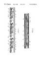
- FIG. 3is a sectional view taken substantially along line 3 — 3 of FIG. 1 .
- FIG. 4is a plan view of a section of the drive rail of the conveyor system of FIG. 1 .
- FIG. 5is an enlarged, pictorial view of a section of the drive rail of FIG. 4 .
- FIG. 6is an enlarged top plan view of the drive rail of FIG. 4 .
- FIGS. 7 and 8are enlarged, sectional views of portions of the transport pod of FIG. 3 .
- FIG. 9is a bottom plan view of the transport pod of FIG. 1 .
- FIG. 10is a bottom plan view of another embodiment of a transport pod.
- FIG. 11is a pictorial view of a conveyor system in accordance with another embodiment of the present invention.
- FIG. 12is a cross sectional view taken substantially along line 12 — 12 of FIG. 11 .
- FIG. 13is an enlarged, sectional view of the circled area of FIG. 12 .
- FIG. 14is a side plan view of another embodiment of a transport device in accordance with the present invention.
- FIG. 15is a front plan view of the transport device of FIG. 14 .
- FIGS. 1 and 2are designated by like reference numerals throughout the various figures.
- FIG. 1shows a section of a conveyor system 10 constructed in accordance with the present invention
- FIG. 2schematically illustrates an example of a possible layout configuration for the conveyor system 10
- the conveyor system 10provides a safe, efficient transport mechanism for moving articles or a protective container or transport pod housing one or more articles.
- several semiconductor wafers W(FIG. 3) are held in the protective environment of a transport pod 8 for transport, although other types of containers may also be used.
- transport podis used throughout the specification as it is a common term employed in the art, although it is to be understood that the term is not to be limited to a holder for wafers but is intended to encompass any type of container for housing any type of articles.
- the system of this inventionmay be used to transport other types of materials, particularly delicate materials where substantial care must be taken in handling the materials such as pharmaceuticals, medical systems, flat panel displays, hard disk drives and other types of computer equipment.
- the conveyor system 10is designed to meet the strict requirements for operation in a clean room environment. However, the system may also be used in other environments where elimination or minimization of particulate contamination is not an issue.
- the conveyor system 10generally includes a pair of rails 12 , 14 for supporting the transport pod 8 as it is moved along the conveyor path.
- the rail 12functions as a drive rail which propels and guides the transport pod 8 along the rails 12 , 14 . All power for moving the pod 8 is supplied via the drive rail 12 .
- Rail 14is an idler or support rail with the sole function of supporting the transport pod 8 such that the pod 8 is held in a level, uniformly balanced orientation as it is moved along the conveyor path.
- the conveyor system 10also includes a transport device for moving the wafers or other materials.
- the transport devicecooperates with the drive rail 12 to constrain movement of the device in both the vertical and lateral directions, while the idler rail 14 cooperates with the transport device to constrain only vertical movement of the transport device.
- the transport deviceis part of the transport pod 8 .
- the conveyor system 10includes a transport device 80 which may be used to carry a transport pod, container, or one or more other articles along the conveyor path.
- the front of the pod 8rests on the drive rail 12 while the rear portion of the pod is supported by the idler rail 14 .
- this configurationcould be reversed, with the idler rail being positioned toward the front of the pod 8 and the drive rail 12 supporting the rear portion of the transport pod.
- the conveyor system 10is particularly suitable for simultaneously transporting a plurality of transport pods 8 or other transport devices.
- Four pods 8are shown in FIG. 2 for illustrative purposes. However, it is to be understood that the number of transport pods 8 carried by the conveyor system 10 may be increased dramatically.
- the drive rail 12 and idler rail 14are arranged in an intra-bay loop 18 which includes one or more cross sections 20 which may be used to transfer the pods 8 from one part of the loop 18 to another without requiring that the pod traverse the entire loop, providing greater flexibility in the movement of the pods 8 .
- This arrangementmay be useful where a manufacturing facility has duplicate processing machines. However, for bays in which each pod must be delivered to each processing machine in succession, a simple continuous loop is preferred as it leaves the middle of the intra-bay loop 18 free for service and maintenance traffic.
- the pods 8are delivered to the intra-bay loop 18 by a stocker 16 which receives the pods from an inter-bay transport system.
- the inter-bay transport systemis preferably elevated to maximize the available space in the inter-bay area for the movement of workers, maintenance and service equipment and the like.
- the conveyor system 10 of this inventionmay be used in the inter-bay area, preferably by suspending the conveyor system 10 from an overhead frame, with the conveyor delivering transport pods to the stockers 16 .
- other types of systemsmay be used for the inter-bay transport device.
- the intra-bay loop 18transports the pods 8 between the semiconductor processing machines 22 positioned in the bay.
- processing machines 22are shown in the bay for illustrative purposes, with the actual number of processing machines located in each bay depending upon the constraints imposed by the specific manufacturing process as well as the physical size of the machines and manufacturing facility.
- the processing machines 22may be any of a variety of types of machines used to process semiconductor wafers including, but not limited to, deposition equipment and machines for cleaning or conditioning the semiconductor wafers at various stages during processing.
- the transport pods 8are moved between the main leg of the intra-bay loop 18 and the cross sections 20 via intersections 26 .
- the intersections 26provide a means of redirecting the pod 8 as it is moved along the drive and idler rails 12 , 14 .
- the intersections 26may take a variety of forms.
- the transport pod 8may be redirected by lifting the pod 8 above the rails 12 , 14 , rotating the pod 90° to insure the same side of the transport pod 8 is always aligned with the drive rail 12 , and lowering the pod onto a portion of the drive rail 12 of the new path.
- the intra-bay loop 18also includes a pair of intersections 28 which join the inward-directed and outward-directed legs of the main path of the intra-bay loop 18 .
- the intersections 28differ from the intersections 26 in that the intersections 28 are used to redirect the section of the conveyor 10 , not to direct the transport pods 8 between two different sections of the conveyor.
- the intersection 28may be constructed to rotate or swing a section of the drive rail 12 to change the orientation of the drive rail 12 , with the drive rail 12 propelling the pod 8 onto and off of the intersection 28 .
- the intersection 28may include a curved drive rail which turns the pod around a corner to change the direction of travel.
- the intersections 28may also be the same as the intersections 26 if desired.
- the layout of the conveyor system 10 shown in FIG. 2also includes transfer assemblies 30 which automatically move the transport pod 8 between the intra-bay loop 18 and the load ports 24 of the processing machines 22 .
- the drive and idler rails 12 , 14are generally located at the level of the load ports 24 .
- the transfer assembly 30includes a lifting mechanism which lifts the transport pod 8 above the drive and idler rails 12 , 14 , separating the pod from the rails.
- the transfer assembly 30also includes a drive system which propels the pod forward until it is properly positioned above the load port 24 , the proper position being determined by the design of the load port.
- Other types of transfer assembliesmay also be used to transfer the transport pod 8 from the conveyor to the load port 24 . Instead of depositing the pod on the load port 24 , it is to be understood that the transfer assembly may be designed to support the transport pod or other article at the machine 22 or other workstation.
- the transport pods 8may be efficiently and conveniently transported between the processing machines within each bay.
- the transport pods 8are automatically coupled to the load port 24 of each machine 22 for unloading and processing of the wafers.
- the pods 8are automatically returned to the rails 12 , 14 and moved along the intra-bay loop.
- the pods 8are safely and securely supported by the conveyor system 10 , the intersections 26 and 28 and the transfer assemblies 30 as the pods are manipulated within the bays, protecting the delicate, expensive wafers from becoming damaged or destroyed during handling.
- the transport pods 8are accelerated, decelerated, and moved in a gentle, controlled manner which minimizes the stresses imposed on the wafers by the motion of the transport pods 8 .
- the conveyor system 10 of this inventionis described in more detail in relation to FIGS. 1 and 3 - 10 .
- the transport pod 8is supported by the drive rail 12 and the idler rail 14 .
- the drive rail 12includes a drive system, generally designated at 38 in FIG. 4, for propelling the pod 8 along the rails 12 , 14 .
- the drive system 38includes a plurality of separate drive assemblies 40 .
- One drive assembly 40is shown in FIG. 5 .
- the drive assemblyincludes a plurality of drive wheels 42 which frictionally engage the underside of the transport pod 8 to propel the transport pod 8 along the drive rail 12 .
- the drive assembly 40includes a plurality of spaced-apart drive wheels 42 . As shown in FIG.
- the drive assemblies 40are located along the rail such that the separation between the outermost drive wheels 42 of adjacent drive assemblies 40 is substantially equal to the spacing between the drive wheels 42 of the individual drive assembly 40 .
- the spacing between the drive assembliesmay be increased or decreased so long as the transport pod 8 can straddle the gap between the drive assemblies 40 and still contact at least one wheel 42 of each assembly 40 .
- the drive wheels 42project upwardly from the drive rail housing 54 such that it is the drive wheels 42 of the rail 12 which directly support the transport pod 8 .
- the wheels 42are preferably mounted at approximately the same height to minimize tipping or rocking of the pod 8 as it is moved along the rails 12 , 14 .
- the drive system 40includes five wheels 42 .
- the drive assemblies 40may have a greater or lesser number of wheels. Further, the size of the wheels may be increased or decreased.
- a hub 44projects outwardly from the drive wheel 42 as shown particularly in FIG 3 .
- a drive belt 46shown particularly in FIGS. 4 and 5, extends around the hubs 44 of the drive wheels 42 to couple the drive wheels to a motor 48 .
- the motors 48may be capable of clockwise and counterclockwise directions of rotation, allowing the transport pods 8 to be moved forward or backward along the rails 12 , 14 upon receipt of appropriate signals.
- the drive system 40also includes at least one tensioner pulley 50 for maintaining a uniform belt tension and at least one idler pulley 51 .
- the drive assemblies 40operate independently, providing greater control over the movement of the transport pod 8 .
- the drive system 38is composed of a plurality of operational zones Z, with each zone Z including one drive assembly 40 .
- the zonesmay each include more than one drive assembly 40 .
- the drive speed and direction (forward or reverse) of each zoneis independently controlled.
- the drive systems 40 of adjacent operational zonesare accelerated and decelerated at the same rate such that at the time of transfer, the speed imposed on the transport pod 8 by the adjacent drive assemblies 40 is synchronized at the time of transfer between the zones.
- the drive zones below and adjacent to other podsmay be held in an inactive mode, allowing a plurality of pods to accumulate in an area of the conveyor, such as before one of the processing machines 22 .
- the moving podsare preferably separated by at least one empty zone, in which there is no pod, to provide a buffer between pods 8 and protect the pods against inadvertently bumping into one another.
- the spacing between the podsis preferably increased as the velocity of the pod increases to provide a safe stopping distance at all times. When they are not in motion, the pods may occupy adjacent drive zones.
- Each zoneincludes one microprocessor or control device 52 for controlling operation of the drive assembly 40 in that zone.
- the control device 52is coupled to a control system (not shown) which controls overall operation of the invention.
- the configuration of the control systemis subject to considerable variation within the scope of this invention.
- the control systemmay include a computer for controlling operation of the conveyor 10 , intersections 26 and 28 , and transfer devices 30 within each bay, with the computer being coupled to the control devices 52 of each of the drive zones as well as the control devices of the intersections 26 , 28 and transfer devices 30 .
- the computermay also monitor the status of the load ports 24 and, when the ports are filled, stop the approaching transport pods 8 at spaced apart locations upstream from the filled load port to prevent collisions between the pods.
- the computers of each baymay be stand-alone systems or the computers may be part of a network which includes the control systems for the inter-bay conveyor, the stockers, and other automated components of the manufacturing facility.
- the central control system of the processing facilitymay also monitor the processing machines.
- each zoneincludes at least one sensor 53 for detecting the presence of a pod 8 within the zone.
- a pair of sensors 53are provided in each zone.
- the sensors 53are located near the entrance and exit of the zone to detect when the pod enters and leaves the zone.
- This data on the location of the pod 8is used to activate the drive zones downstream from the sensor such that the wheels 42 are active and operating at the same speed as the wheels 42 in the previous zone when the pod reaches the zone.
- the datais also used to deactivate drive assemblies after the pod 8 has left the operational zone.
- the time required for the pod to travel between the sensorsmay be used to monitor the actual speed of the pod as it travels across the zone.
- the sensorsare used to monitor the location of each of the transport pods 8 and increase or decrease the speed of the individual transport pods 8 accordingly.
- the drive system 38 of the illustrated embodimentprovides a clean, efficient drive mechanism for moving the pod 8 along the drive rail 12 in a precise controlled manner.
- the drive systemmay be provided by linear induction motors, with the transport device including a magnet or suitable metal for driving the pod in response to the linear induction motors.
- Other drive systemsmay also be employed.
- the independent drive assemblies 40 of this inventionthe movement of several pods may be independently controlled. Thus, synchronization of the transport pods 8 along the loops or precise control over the spacing between the pods 8 along the conveyor system 10 is not required. Using one common drive system would not permit such precise control over the drive speed.
- the drive wheel 42cooperates with the transport device, which in this embodiment is part of the transport pod 8 , to propel and guide the pod 8 along the path.
- the drive wheel 42engages a groove 56 formed in the underside of the pod 8 .
- the side rails of the groove 56are tapered outwardly to minimize contact between the walls of the groove and the drive wheels 42 , minimizing friction between the wheels 42 and the groove 56 and reducing wear and tear on the wheels. This is of particular advantage when the conveyor 10 is used in a clean room environment where minimizing sources of particulate contamination is important.
- a groove configurationin which there is some contact between the walls of the groove and the wheels may be employed.
- the groove 56 of this embodimenthas a depth of about 5 mm, with the tapered side walls having a height of about 3.5 mm.
- the width of the bottom of the grooveis about 8.5 mm, with the side walls being oriented at an angle of 30°.
- the groove 56defines the horizontal plane in which the pods sits on the drive wheels 42 .
- the engagement between the drive wheels 42 and the groove 56controls lateral or side-to-side movement of the pod 8 as well as vertical movement of the pod. While the combination of the groove 56 and drive wheels 42 is preferred, it is to be understood that the groove 56 may be eliminated entirely provided the transport device, drive rail 12 or idler rail 14 include a guiding device for guiding the pod 8 as it moves along the rails 12 , 14 .
- the idler rail 14cooperates with the transport device, which in this embodiment is part of the transport pod 8 , to support one side of the transport pod 8 .
- the drive rail 12controls the plane of the pod as it sits on the drive rail 12 as well as the lateral position of the pod.
- the transport pod 8is supported on the idler rail 14 in a manner which minimizes bumping, jolting or shimmying of the pod 8 as it is propelled along the rails.
- the idler rail 14has little effect, if any, on the smooth, controlled movement of the transport pod 8 along the rails 12 , 14 . As shown particularly in FIGS.
- the idler rail 14is parallel to and spaced from the drive rail 12 .
- One or more connectors 60are mounted to the drive and idler rails 12 , 14 to maintain a predetermined spacing between the rails and facilitate installation of the conveyor.
- the connector 60may extend the entire length of the rails 12 , 14 , or the connector 60 may be provided by a plurality of connecting members positioned at intervals along the rails 12 , 14 .
- the drive rail 12 and connectors 60may be mounted to a suitable mounting frame (not shown). Alternatively, the drive and idler rails 12 , 14 may be suspended from the ceiling by an overhead frame (not shown).
- the components of the conveyor systemare mounted to the supporting structure using suitable means as is known in the art.
- the conveyor 10 of the illustrated embodimentis provided with a first pair of mounting channels 62 which may be used to mount the conveyor to a floor support frame, and a second pair of channels 64 which may be used to mount the conveyor to an overhead support frame.
- the pod 8rides along the upper surface of the idler rail 14 as discussed in more detail below.
- a pad or cushion material 67is provided along the upper surface of the rail 14 to provide the pod with a smoother ride.
- the pad 67is formed of a resilient material such as urethane which will not readily shed particles after the conveyor has been in use for extended periods of time.
- the pod 8may ride directly on the upper surface of the rail 14 .
- the upper surface of the pad 67 , or the rail 14 if no pad is employed,is preferably a planar surface having a substantially horizontal orientation. However, the surface may also have a different topography.
- the idler rail 14may be in the form of a V-rail.
- the upper surfacemay be provided with a longitudinally extending groove (not shown) to ensure the transport pod 8 does not begin to veer off of the rails 12 , 14 .
- This designis not feasible for clean room applications as the groove in the rail 14 provides a trap for dirt and other particulate contamination.
- the variations in the configuration of the idler rail 14 which may be used to guide the pod 8may be provided instead of the groove 56 , or in addition to the groove 56 provided they do not compete in guiding the pod.
- the transport pod 8includes a shoe 68 which rides along the upper surface of the idler rail 14 .
- the shoe 68is provided by a wheel 70 .
- the wheel 70is rotatably mounted to the transport pod 8 via a shaft 72 .
- the shaft 72may be supported in sealed bearings (not shown) carried by the transport pod 8 , although other means may be used to mount the shaft to the transport pod 8 .
- the wheel 70is preferably formed of plastic with integral sealed ball bearings or another material which is suitable for use in a clean room environment.
- the thickness of the wheel 70is preferably greater than the width of the pad 67 .
- a narrower wheelmay form a groove in the surface of the pad 67 over time, creating a source of friction as the sides of the wheels rub against the pad and a trap for dirt and other particulate contamination.
- wheels having a width equal to or narrower than the width of the pad 67may be employed in non-clean room environments.
- the wheel 70may be provided with an annular groove of sufficient width to receive the upper surface of the rail 14 .
- the raised edges of the wheel on opposite sides of the groovewould extend below the upper surface of the rail 14 and ensure the wheel 70 remained squarely on the upper surface of the rail 14 as the transport pod 8 is propelled along the conveyor.
- the side walls of the groove in the wheelwould be tapered outwardly to minimize contact between the side walls and the sides of the idler rail 14 .
- the wheel 70mounted to the base of the pod 8 .
- the wheel 70is positioned in a groove 74 which is wider than the width of the upper surface of the idler rail 14 , and preferably sufficiently wider such that the walls of the groove 74 do not contact the idler rail 14 .
- the wheel 70projects from the surface of the transport pod 8 , about 1 mm.
- the wheelmay project further than 1 mm or the wheel 70 may be recessed into the groove 74 .
- the groove 74may be eliminated.
- the transport pod 8includes a single wheel 70 .
- One limitation on the location of the wheel 70is the location of the slots 78 on the underside of the pod which cooperate with the kinematic pins on the load port 24 to accurately position the pod 8 on the load port.
- the wheel 70is located near the back edge of the pod 8 to maximize the spacing between the drive and idler rails 12 , 14 for the use of auxiliary devices therebetween, and midway between the sides of the pod 8 to support the back portion of the pod 8 in a level orientation and prevent the pod 8 from tipping and hitting the rail. It is to be understood that the wheel 70 may also be located at different positions.
- FIG. 10shows an example of a transport pod 8 which includes two shoes 68 .
- both shoes 68are provided by a wheel 70 which are each rotatably mounted to the transport pod by a shaft 72 .
- FIGS. 11-13show another modification of the invention.
- the transport deviceis again part of transport pod 86 .
- the transport device of this embodimentmay instead be provided by a sled, pallet or other device which can support a transport pod, a container, or one or more other articles.
- the drive wheels 42engage the bottom surface of the pod 86 to propel the pod along the conveyor.
- the bottom surface of the pod 86does not include the groove 56 of the previous embodiment but is instead substantially flat.
- the drive wheelspropel the pod and determine the height or horizontal plane of the pod, the drive wheels 42 do not control the lateral or side-to-side movement of the pod.
- the pod 86includes a pair of shoes 88 mounted to the wall 90 of the pod 86 .
- the pod 86includes an information device 92 which is used in the art to store production information about the lot as the pod 86 is moved along the conveyor and the shoes 88 are positioned on either side of the information device 92 .
- Each shoe 88includes a housing 94 which rotatably supports a wheel 96 .
- the wheel 96has a groove 98 formed therein which rides on the v-shaped idler rail 14 .
- the groove 98 and idler rail 14cooperate to guide the transport pod 86 as it is moved along the rails 12 , 14 , thereby controlling lateral or side-to-side movement of the pod 86 .
- the wheel 96also controls the vertical position of the respective end of the pod 86 .
- the idler rail 14is spaced outwardly of the pod 86 , increasing the gap between the idler rail 14 and drive rail 12 which may be used to accommodate auxiliary devices.
- the idler rail 14is also positioned above the drive rail 12 .
- One or more connecting membersjoin the idler and drive rails to accurately control the spacing between the rails and to ensure the idler rail 14 is positioned at the proper height above the drive rail 12 .
- the transport pod 8serves the dual function of the pod 8 which houses the wafers in a protective environment and the transport device which moves along the rails 12 , 14 .
- this inventionis not to be limited to a transport pod which serves this dual role.
- the transport deviceis separate from the pod or other container holding the wafers.
- This modification of the inventionis also particularly suitable for use with applications other than semiconductor processing, where the transport device may be used to carry one or more articles or a container holding one or more articles.
- the configuration of the separate transport deviceis subject to considerable variation, depending in part upon the constraints imposed by the particular application.
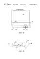
- FIGS. 14 and 15show an example of a transport device 100 in accordance with the modified embodiment of the invention. However, the transport device is not to be limited to the configuration shown in FIGS. 14 and 15.
- the transport device 100is used with the drive and idler rails 12 , 14 shown in FIGS. 1-5, and reference is made to the description of these figures.
- the transport device 100is shown holding a transport pod 102 which holds a plurality of wafers.
- the transport device 100may be used to carry other articles or materials within the scope of this invention, or other types of containers.
- the transport device 100is provided by a sled which includes a base 104 and side walls 106 which extend upwardly from three sides of the base 104 .
- the base 104has pins 118 (FIG. 15) formed thereon which mirror the kinematic pins on the load port.
- the pins 118engage the kinematic pin slots (not shown) on the underside of the pod to hold the pod in place.
- the side walls 106are positioned just outside of the outer walls of the transport pod 102 so that the pod 102 fits snugly within the transport device 100 , providing additional support and preventing rocking or shifting of the pod as the transport device 100 is moved along the conveyor. If desired, other means may be used instead of or in addition to the side walls 106 to securely hold the transport pod 102 on the device 100 .
- the device 100may be secured to the sides and/or bottom of the transport pod 102 by bolts or other suitable fasteners.
- the transport pod 102may also be secured to the transport device 100 using straps or other suitable means of attachment.
- the transport pod 102is positioned on the upper surface 108 of the base 104 .
- the base 104may be provided with one or more inward-extending grooves 110 to facilitate loading of the transport pod 102 onto the base 104 .
- the underside of the base 104is provided with a groove 112 and at least one shoe 114 and kinematic pin slots (not shown) which cooperate with the pins on the load port 24 .
- the shoe 114is provided by a wheel 116 rotatably mounted to the base 104 .
- the groove 112 and shoe 114are similar to the groove 56 and shoe 68 of the previous embodiments and are not described in detail, reference being made to the previous description.
- transport device 100 of the embodiment shown in FIGS. 14 and 15does not require a specific pod design. Instead, the transport device 100 may be used with transport pods or other types of containers which are currently being used to house semiconductor wafers.
- the components of the system 10are constructed of materials which are suitable for use in a clean room environment. In other words, operation of the components over extended periods of time will not generate significant levels of particulate contamination. These constraints will not be present for other applications of the conveyor 10 of this invention which do not require a clean room environment. For non-clean room environments, materials which do not meet clean room standards may be employed for all components of the conveyor system 10 .
Landscapes
- Engineering & Computer Science (AREA)
- Microelectronics & Electronic Packaging (AREA)
- Condensed Matter Physics & Semiconductors (AREA)
- General Physics & Mathematics (AREA)
- Manufacturing & Machinery (AREA)
- Computer Hardware Design (AREA)
- Physics & Mathematics (AREA)
- Power Engineering (AREA)
- Mechanical Engineering (AREA)
- Container, Conveyance, Adherence, Positioning, Of Wafer (AREA)
- Warehouses Or Storage Devices (AREA)
- Intermediate Stations On Conveyors (AREA)
- Control Of Conveyors (AREA)
- Rollers For Roller Conveyors For Transfer (AREA)
Abstract
Description
Claims (21)
Priority Applications (12)
| Application Number | Priority Date | Filing Date | Title |
|---|---|---|---|
| US09/103,479US6223886B1 (en) | 1998-06-24 | 1998-06-24 | Integrated roller transport pod and asynchronous conveyor |
| TW088110577ATW430630B (en) | 1998-06-24 | 1999-06-23 | Integrated roller transport pod and asynchronous conveyor |
| AU47203/99AAU4720399A (en) | 1998-06-24 | 1999-06-24 | Integrated roller transport pod and asynchronous conveyor |
| CA002335054ACA2335054A1 (en) | 1998-06-24 | 1999-06-24 | Integrated roller transport pod and asynchronous conveyor |
| KR10-2000-7014827AKR100432380B1 (en) | 1998-06-24 | 1999-06-24 | Protective container, conveyor and method for transporting articles |
| PCT/US1999/014425WO1999067158A2 (en) | 1998-06-24 | 1999-06-24 | Integrated roller transport pod and asynchronous conveyor |
| EP99930726AEP1334051A2 (en) | 1998-06-24 | 1999-06-24 | Integrated roller transport pod and asynchronous conveyor |
| CNB998077453ACN1231401C (en) | 1998-06-24 | 1999-06-24 | Integrated roller transport pod and asynchronous conveyor |
| JP2000555819AJP2003524544A (en) | 1998-06-24 | 1999-06-24 | Integrated roller transport pod and asynchronous conveyor |
| IL14019599AIL140195A0 (en) | 1998-06-24 | 1999-06-24 | Integrated roller transport pod and asynchronous conveyor |
| US09/781,060US6494308B2 (en) | 1998-06-24 | 2001-02-08 | Integrated roller transport pod and asynchronous conveyor |
| US10/123,850US6533101B2 (en) | 1998-06-24 | 2002-04-16 | Integrated transport carrier and conveyor system |
Applications Claiming Priority (1)
| Application Number | Priority Date | Filing Date | Title |
|---|---|---|---|
| US09/103,479US6223886B1 (en) | 1998-06-24 | 1998-06-24 | Integrated roller transport pod and asynchronous conveyor |
Related Child Applications (2)
| Application Number | Title | Priority Date | Filing Date |
|---|---|---|---|
| US46698999AContinuation-In-Part | 1998-06-24 | 1999-12-10 | |
| US09/781,060DivisionUS6494308B2 (en) | 1998-06-24 | 2001-02-08 | Integrated roller transport pod and asynchronous conveyor |
Publications (1)
| Publication Number | Publication Date |
|---|---|
| US6223886B1true US6223886B1 (en) | 2001-05-01 |
Family
ID=22295415
Family Applications (2)
| Application Number | Title | Priority Date | Filing Date |
|---|---|---|---|
| US09/103,479Expired - Fee RelatedUS6223886B1 (en) | 1998-06-24 | 1998-06-24 | Integrated roller transport pod and asynchronous conveyor |
| US09/781,060Expired - LifetimeUS6494308B2 (en) | 1998-06-24 | 2001-02-08 | Integrated roller transport pod and asynchronous conveyor |
Family Applications After (1)
| Application Number | Title | Priority Date | Filing Date |
|---|---|---|---|
| US09/781,060Expired - LifetimeUS6494308B2 (en) | 1998-06-24 | 2001-02-08 | Integrated roller transport pod and asynchronous conveyor |
Country Status (10)
| Country | Link |
|---|---|
| US (2) | US6223886B1 (en) |
| EP (1) | EP1334051A2 (en) |
| JP (1) | JP2003524544A (en) |
| KR (1) | KR100432380B1 (en) |
| CN (1) | CN1231401C (en) |
| AU (1) | AU4720399A (en) |
| CA (1) | CA2335054A1 (en) |
| IL (1) | IL140195A0 (en) |
| TW (1) | TW430630B (en) |
| WO (1) | WO1999067158A2 (en) |
Cited By (31)
| Publication number | Priority date | Publication date | Assignee | Title |
|---|---|---|---|---|
| US20010023377A1 (en)* | 1998-12-14 | 2001-09-20 | Palo Alto Technologies, Inc. | Distributed control system architecture and method for a material transport system |
| WO2002059738A1 (en)* | 2001-01-26 | 2002-08-01 | Asyst Technologies, Inc. | Control system for transfer and buffering |
| US6494308B2 (en)* | 1998-06-24 | 2002-12-17 | Asyst Technologies, Inc. | Integrated roller transport pod and asynchronous conveyor |
| US6533101B2 (en) | 1998-06-24 | 2003-03-18 | Asyst Technologies, Inc. | Integrated transport carrier and conveyor system |
| US6595347B2 (en)* | 2001-01-15 | 2003-07-22 | Prodel Holding | Installation for the circulation of part-carrying pallets and a pallet for said installation |
| US20030209404A1 (en)* | 2000-07-07 | 2003-11-13 | Davis Jeffry A. | Automated processing system |
| US20040025712A1 (en)* | 2000-09-22 | 2004-02-12 | Mikael Jarvenkyla | Production line for food products |
| US6692196B1 (en)* | 1999-02-19 | 2004-02-17 | The Procter & Gamble Company | Apparatus for manufacturing hygienic articles |
| US6726429B2 (en) | 2002-02-19 | 2004-04-27 | Vertical Solutions, Inc. | Local store for a wafer processing station |
| US20040080852A1 (en)* | 2002-10-18 | 2004-04-29 | Seagate Technology Llc | Disc caddy feeder system with caddy gripper for data storage devices |
| US20040136818A1 (en)* | 2002-12-16 | 2004-07-15 | Seagate Technology Llc | Disc cassette delidder and feeder system for data storage devices |
| US20040181929A1 (en)* | 2003-03-21 | 2004-09-23 | Mariano Thomas R. | Growth model automated material handling system |
| US6821082B2 (en)* | 2001-10-30 | 2004-11-23 | Freescale Semiconductor, Inc. | Wafer management system and methods for managing wafers |
| US6942738B1 (en)* | 1996-07-15 | 2005-09-13 | Semitool, Inc. | Automated semiconductor processing system |
| US20070010908A1 (en)* | 2005-07-11 | 2007-01-11 | Bonora Anthony C | Belt conveyor for use with semiconductor containers |
| CN1307685C (en)* | 2003-12-05 | 2007-03-28 | 财团法人工业技术研究院 | Interlock Motion Control Method |
| US20070151897A1 (en)* | 2005-12-29 | 2007-07-05 | Shin-Etsu Polymer Co., Ltd. | Substrate storage container |
| US7281623B1 (en) | 2006-04-18 | 2007-10-16 | Aquest Systems Corporation | Transport system including vertical rollers |
| US20070289843A1 (en)* | 2006-04-18 | 2007-12-20 | Barry Kitazumi | Conveyor System Including Offset Section |
| US20080050208A1 (en)* | 2006-08-25 | 2008-02-28 | Barry Kitazumi | High speed transporter including horizontal belt |
| US20080053794A1 (en)* | 2006-08-25 | 2008-03-06 | Brain Michael D | Conveyor transfer system |
| US20080152466A1 (en)* | 2006-12-22 | 2008-06-26 | Bonora Anthony C | Loader and buffer for reduced lot size |
| CN101811623A (en)* | 2010-04-07 | 2010-08-25 | 友达光电股份有限公司 | Conveying device |
| US20100219050A1 (en)* | 2006-07-10 | 2010-09-02 | Roumen Deyanov | Direct drive modular belt conveyor, cartridge, and quick connect-disconnect constant velocity drive shaft, for high speed foup transport |
| US20100314224A1 (en)* | 2008-04-07 | 2010-12-16 | Asyst Technologies, Inc. | Segmented material conveyor system, threshold assembly and method for making and using the same |
| KR101215220B1 (en) | 2009-09-23 | 2012-12-24 | 크린팩토메이션 주식회사 | Conveyor for foup transferring |
| US8827618B2 (en)* | 2011-12-02 | 2014-09-09 | Brooks Automation, Inc. | Transport system |
| US20160035607A1 (en)* | 2014-07-30 | 2016-02-04 | Samsung Electronics Co., Ltd. | Semiconductor wafer stocker apparatus and wafer transferring methods using the same |
| US20160236872A1 (en)* | 2013-10-28 | 2016-08-18 | Murata Machinery, Ltd. | Conveyor Device |
| CN112705971A (en)* | 2020-12-16 | 2021-04-27 | 福建中维动力科技股份有限公司 | Feeding mechanism for heavy truck plate-shaped part overturning and positioning device |
| US20220274632A1 (en)* | 2019-07-25 | 2022-09-01 | Holmes Solutions Limited Partnership | System and Method of Transporting Objects |
Families Citing this family (32)
| Publication number | Priority date | Publication date | Assignee | Title |
|---|---|---|---|---|
| US6308818B1 (en)* | 1999-08-02 | 2001-10-30 | Asyst Technologies, Inc. | Transport system with integrated transport carrier and directors |
| US7077264B2 (en) | 2003-01-27 | 2006-07-18 | Applied Material, Inc. | Methods and apparatus for transporting substrate carriers |
| EP1750299B1 (en)* | 2003-01-27 | 2008-06-11 | Applied Materials, Inc. | Apparatus for transporting substrate carriers |
| DE10321915B3 (en)* | 2003-05-15 | 2005-06-09 | Siemens Ag | Slope for a container conveyor system, in particular an airport baggage conveyor system |
| DE10348091A1 (en)* | 2003-10-16 | 2005-05-19 | Kolbus Gmbh & Co. Kg | Conveyor with profiled sidewalls |
| US20050095087A1 (en)* | 2003-10-30 | 2005-05-05 | Sullivan Robert P. | Automated material handling system |
| WO2006008818A1 (en) | 2004-07-22 | 2006-01-26 | Hirata Corporation | Conveying apparatus |
| JP2006191039A (en)* | 2005-01-05 | 2006-07-20 | Samsung Sdi Co Ltd | Tray transfer device |
| CN100388455C (en)* | 2005-09-29 | 2008-05-14 | 中芯国际集成电路制造(上海)有限公司 | Guide track transmissioner of crystal-boat box with safety baffle |
| US20080107507A1 (en)* | 2005-11-07 | 2008-05-08 | Bufano Michael L | Reduced capacity carrier, transport, load port, buffer system |
| KR20080075164A (en)* | 2005-11-07 | 2008-08-14 | 브룩스 오토메이션 인코퍼레이티드 | Reduced capacity carriers, conveyers, load ports and buffer systems |
| US8272827B2 (en)* | 2005-11-07 | 2012-09-25 | Bufano Michael L | Reduced capacity carrier, transport, load port, buffer system |
| US8267634B2 (en) | 2005-11-07 | 2012-09-18 | Brooks Automation, Inc. | Reduced capacity carrier, transport, load port, buffer system |
| WO2008142766A1 (en)* | 2007-05-21 | 2008-11-27 | Hirata Corporation | Workpiece holder unit and conveyor system |
| JP5169023B2 (en)* | 2007-05-23 | 2013-03-27 | 村田機械株式会社 | Transport system |
| US20100080672A1 (en)* | 2008-06-20 | 2010-04-01 | Asyst Technologies, Inc. | Direct loading to and from a conveyor system |
| DE102008045370B4 (en)* | 2008-09-02 | 2010-07-08 | Grenzebach Maschinenbau Gmbh | Method and device for transporting large-area, thin glass plates |
| FR2944266B1 (en)* | 2009-04-08 | 2014-04-11 | Philippe Moutie | STORAGE DEVICE AND IMPROVED TRANSPORT SYSTEM |
| WO2011065146A1 (en)* | 2009-11-27 | 2011-06-03 | 株式会社ダイフク | Ceiling conveyor car |
| JP5827069B2 (en)* | 2011-08-11 | 2015-12-02 | 平田機工株式会社 | Transport device |
| KR20130117143A (en)* | 2012-04-17 | 2013-10-25 | 삼성전자주식회사 | Hoist apparatus |
| CN104176430A (en)* | 2013-05-28 | 2014-12-03 | 北京中电科电子装备有限公司 | Workpiece delivery device |
| TWI554464B (en)* | 2015-06-22 | 2016-10-21 | 盟立自動化股份有限公司 | Transporting device and transporting system using the same |
| KR102394712B1 (en)* | 2015-09-09 | 2022-05-04 | 삼성전자주식회사 | Transporting system, transporting unit included therein |
| CN107321718A (en)* | 2017-08-14 | 2017-11-07 | 惠科股份有限公司 | Display panel placing rack conveying device |
| JP6868223B2 (en)* | 2018-05-18 | 2021-05-12 | 株式会社ダイフク | Curve conveyor |
| DE102019125207A1 (en)* | 2019-09-19 | 2021-03-25 | Markus Steckling | Device and method for the production of small parts |
| CN110980162B (en)* | 2019-12-20 | 2021-04-30 | 安徽天兵电子科技股份有限公司 | Processing conveyor of circuit board |
| KR102720391B1 (en) | 2020-01-21 | 2024-10-21 | 에스케이하이닉스 주식회사 | conveyor APPARATUS for carrier and operating method thereof |
| US20220406638A1 (en)* | 2021-06-17 | 2022-12-22 | Taiwan Semiconductor Manufacturing Company, Ltd. | Hash overhead hoist transport rail system and methods of operating the same |
| US12046497B2 (en)* | 2022-08-02 | 2024-07-23 | Visera Technologies Company Ltd. | Transfer system for wafer cassettes |
| CN116177175B (en)* | 2023-01-31 | 2024-01-30 | 果栗智造(上海)技术股份有限公司 | Connecting device and conveying line body |
Citations (33)
| Publication number | Priority date | Publication date | Assignee | Title |
|---|---|---|---|---|
| US3746148A (en)* | 1972-03-08 | 1973-07-17 | Logan Co | Shuttle car mechanism for transferring loads between two stations |
| US3840110A (en) | 1972-07-24 | 1974-10-08 | Ermanco Inc | Conveyor apparatus |
| US3927620A (en) | 1973-12-03 | 1975-12-23 | Thomas J Clapham | Magnetic propulsion system |
| US3976330A (en) | 1975-10-01 | 1976-08-24 | International Business Machines Corporation | Transport system for semiconductor wafer multiprocessing station system |
| US4014428A (en)* | 1973-05-04 | 1977-03-29 | Ossbahr C | Modular article conveyor |
| US4093084A (en) | 1974-08-24 | 1978-06-06 | Karl Ringer | Freight-transportation system with road/rail transshipment |
| US4305335A (en)* | 1978-05-16 | 1981-12-15 | Staat Der Nederlanden (Staatsbedrijf Der Posterijen, Telegrafie En Telefonie) | Endless conveyor for transporting roll containers |
| US4389941A (en) | 1980-11-21 | 1983-06-28 | Si Handling Systems Inc. | Driverless vehicle conveyor system |
| US4453627A (en) | 1980-02-08 | 1984-06-12 | The E. W. Buschman Co. | Accumulator conveyor |
| US4461382A (en) | 1981-11-16 | 1984-07-24 | Pentek Corporation | Motion detector and control system for an accumulating live conveyor |
| US4513854A (en)* | 1982-03-05 | 1985-04-30 | Maurice Prodel | Machines for assembling or for machining parts |
| US4515264A (en)* | 1982-03-05 | 1985-05-07 | Stiwa-Fertigungstechnik Sticht Gesellschaft M.B.H. | Assembly line |
| US4530287A (en) | 1982-03-05 | 1985-07-23 | Stiwa-Fertigungstechnik Sticht Gesellschaft M.B.H. | Conveyor arrangement |
| US4534462A (en) | 1981-11-16 | 1985-08-13 | Pentek Corporation | Motion detector and control system for an accumulating live conveyor |
| US4572358A (en) | 1981-03-10 | 1986-02-25 | Rexnord Inc. | Powered transmission assembly for an accumulating conveyor |
| US4619205A (en)* | 1983-03-29 | 1986-10-28 | Stiwa-Fertigungstechnik Sticht Gesmbh | Conveyor arrangement |
| US4793262A (en) | 1987-10-03 | 1988-12-27 | Middlesex General Industries, Inc. | Transport system for computer integrated manufacturing/storage and drive component therefor |
| US4805759A (en)* | 1985-04-12 | 1989-02-21 | Societe Pour L'etude Et La Fabrication De Circuits Integres Speciaux Efcis | Installation and method for handling delicate objects in an atmosphere having a controlled dust content |
| US4826360A (en)* | 1986-03-10 | 1989-05-02 | Shimizu Construction Co., Ltd. | Transfer system in a clean room |
| US4926753A (en) | 1986-04-29 | 1990-05-22 | Programmation, Inc. | Flexible material transport system |
| US4940000A (en) | 1985-07-17 | 1990-07-10 | Sysmo S.A. | Modular installation for controlled transport of parts or products |
| US4974519A (en)* | 1988-11-10 | 1990-12-04 | Ism Equipments Industriels De Montage S.A. | Transfer system with pallets having wheels comprised of two rollers, driven by a belt |
| US5009306A (en) | 1989-06-19 | 1991-04-23 | Simplimatic Engineering Company | Printed circuit board conveyor and method |
| US5086910A (en) | 1990-08-13 | 1992-02-11 | Giddings & Lewis, Inc. | Zone controlled conveyance system |
| US5129507A (en) | 1990-03-08 | 1992-07-14 | Daifuku Co. Ltd. | Roller conveyor |
| US5213201A (en) | 1991-01-31 | 1993-05-25 | Bavaria Cargo Technologie Gmbh | Electronic control assembly for drive roller units |
| US5285887A (en) | 1992-11-23 | 1994-02-15 | Interroll Holding A. G. | Accumulating conveyor and control system |
| US5318167A (en) | 1993-03-12 | 1994-06-07 | Newcor, Inc. | Control system for power driven conveyor line |
| US5452801A (en)* | 1994-07-13 | 1995-09-26 | Middlesex General Industries, Inc. | Conveyor cassette for wafers |
| EP0674069A1 (en) | 1994-03-22 | 1995-09-27 | Manfred Kobler | Arrangement and method for realising building constructions using masonry blocks and/or shutterings |
| US5521563A (en) | 1995-06-05 | 1996-05-28 | Emc Technology, Inc. | Microwave hybrid coupler |
| US5533844A (en) | 1994-11-15 | 1996-07-09 | Ekleberry; Donald A. | Travelling platen with extended axis |
| US5673804A (en) | 1996-12-20 | 1997-10-07 | Pri Automation, Inc. | Hoist system having triangular tension members |
Family Cites Families (3)
| Publication number | Priority date | Publication date | Assignee | Title |
|---|---|---|---|---|
| JPH1159829A (en)* | 1997-08-08 | 1999-03-02 | Mitsubishi Electric Corp | Semiconductor wafer cassette transfer device, stocker used in semiconductor wafer cassette transfer device, stocker entry work control method, stocker exit work control method, automatic transfer vehicle control method, and stocker stock collation method used in semiconductor wafer cassette transfer device |
| US6223886B1 (en)* | 1998-06-24 | 2001-05-01 | Asyst Technologies, Inc. | Integrated roller transport pod and asynchronous conveyor |
| US6308818B1 (en)* | 1999-08-02 | 2001-10-30 | Asyst Technologies, Inc. | Transport system with integrated transport carrier and directors |
- 1998
- 1998-06-24USUS09/103,479patent/US6223886B1/ennot_activeExpired - Fee Related
- 1999
- 1999-06-23TWTW088110577Apatent/TW430630B/ennot_activeIP Right Cessation
- 1999-06-24JPJP2000555819Apatent/JP2003524544A/enactivePending
- 1999-06-24ILIL14019599Apatent/IL140195A0/enunknown
- 1999-06-24WOPCT/US1999/014425patent/WO1999067158A2/ennot_activeApplication Discontinuation
- 1999-06-24CNCNB998077453Apatent/CN1231401C/ennot_activeExpired - Fee Related
- 1999-06-24CACA002335054Apatent/CA2335054A1/ennot_activeAbandoned
- 1999-06-24KRKR10-2000-7014827Apatent/KR100432380B1/ennot_activeExpired - Fee Related
- 1999-06-24AUAU47203/99Apatent/AU4720399A/ennot_activeAbandoned
- 1999-06-24EPEP99930726Apatent/EP1334051A2/ennot_activeWithdrawn
- 2001
- 2001-02-08USUS09/781,060patent/US6494308B2/ennot_activeExpired - Lifetime
Patent Citations (33)
| Publication number | Priority date | Publication date | Assignee | Title |
|---|---|---|---|---|
| US3746148A (en)* | 1972-03-08 | 1973-07-17 | Logan Co | Shuttle car mechanism for transferring loads between two stations |
| US3840110A (en) | 1972-07-24 | 1974-10-08 | Ermanco Inc | Conveyor apparatus |
| US4014428A (en)* | 1973-05-04 | 1977-03-29 | Ossbahr C | Modular article conveyor |
| US3927620A (en) | 1973-12-03 | 1975-12-23 | Thomas J Clapham | Magnetic propulsion system |
| US4093084A (en) | 1974-08-24 | 1978-06-06 | Karl Ringer | Freight-transportation system with road/rail transshipment |
| US3976330A (en) | 1975-10-01 | 1976-08-24 | International Business Machines Corporation | Transport system for semiconductor wafer multiprocessing station system |
| US4305335A (en)* | 1978-05-16 | 1981-12-15 | Staat Der Nederlanden (Staatsbedrijf Der Posterijen, Telegrafie En Telefonie) | Endless conveyor for transporting roll containers |
| US4453627A (en) | 1980-02-08 | 1984-06-12 | The E. W. Buschman Co. | Accumulator conveyor |
| US4389941A (en) | 1980-11-21 | 1983-06-28 | Si Handling Systems Inc. | Driverless vehicle conveyor system |
| US4572358A (en) | 1981-03-10 | 1986-02-25 | Rexnord Inc. | Powered transmission assembly for an accumulating conveyor |
| US4534462A (en) | 1981-11-16 | 1985-08-13 | Pentek Corporation | Motion detector and control system for an accumulating live conveyor |
| US4461382A (en) | 1981-11-16 | 1984-07-24 | Pentek Corporation | Motion detector and control system for an accumulating live conveyor |
| US4513854A (en)* | 1982-03-05 | 1985-04-30 | Maurice Prodel | Machines for assembling or for machining parts |
| US4530287A (en) | 1982-03-05 | 1985-07-23 | Stiwa-Fertigungstechnik Sticht Gesellschaft M.B.H. | Conveyor arrangement |
| US4515264A (en)* | 1982-03-05 | 1985-05-07 | Stiwa-Fertigungstechnik Sticht Gesellschaft M.B.H. | Assembly line |
| US4619205A (en)* | 1983-03-29 | 1986-10-28 | Stiwa-Fertigungstechnik Sticht Gesmbh | Conveyor arrangement |
| US4805759A (en)* | 1985-04-12 | 1989-02-21 | Societe Pour L'etude Et La Fabrication De Circuits Integres Speciaux Efcis | Installation and method for handling delicate objects in an atmosphere having a controlled dust content |
| US4940000A (en) | 1985-07-17 | 1990-07-10 | Sysmo S.A. | Modular installation for controlled transport of parts or products |
| US4826360A (en)* | 1986-03-10 | 1989-05-02 | Shimizu Construction Co., Ltd. | Transfer system in a clean room |
| US4926753A (en) | 1986-04-29 | 1990-05-22 | Programmation, Inc. | Flexible material transport system |
| US4793262A (en) | 1987-10-03 | 1988-12-27 | Middlesex General Industries, Inc. | Transport system for computer integrated manufacturing/storage and drive component therefor |
| US4974519A (en)* | 1988-11-10 | 1990-12-04 | Ism Equipments Industriels De Montage S.A. | Transfer system with pallets having wheels comprised of two rollers, driven by a belt |
| US5009306A (en) | 1989-06-19 | 1991-04-23 | Simplimatic Engineering Company | Printed circuit board conveyor and method |
| US5129507A (en) | 1990-03-08 | 1992-07-14 | Daifuku Co. Ltd. | Roller conveyor |
| US5086910A (en) | 1990-08-13 | 1992-02-11 | Giddings & Lewis, Inc. | Zone controlled conveyance system |
| US5213201A (en) | 1991-01-31 | 1993-05-25 | Bavaria Cargo Technologie Gmbh | Electronic control assembly for drive roller units |
| US5285887A (en) | 1992-11-23 | 1994-02-15 | Interroll Holding A. G. | Accumulating conveyor and control system |
| US5318167A (en) | 1993-03-12 | 1994-06-07 | Newcor, Inc. | Control system for power driven conveyor line |
| EP0674069A1 (en) | 1994-03-22 | 1995-09-27 | Manfred Kobler | Arrangement and method for realising building constructions using masonry blocks and/or shutterings |
| US5452801A (en)* | 1994-07-13 | 1995-09-26 | Middlesex General Industries, Inc. | Conveyor cassette for wafers |
| US5533844A (en) | 1994-11-15 | 1996-07-09 | Ekleberry; Donald A. | Travelling platen with extended axis |
| US5521563A (en) | 1995-06-05 | 1996-05-28 | Emc Technology, Inc. | Microwave hybrid coupler |
| US5673804A (en) | 1996-12-20 | 1997-10-07 | Pri Automation, Inc. | Hoist system having triangular tension members |
Cited By (50)
| Publication number | Priority date | Publication date | Assignee | Title |
|---|---|---|---|---|
| US6942738B1 (en)* | 1996-07-15 | 2005-09-13 | Semitool, Inc. | Automated semiconductor processing system |
| US6494308B2 (en)* | 1998-06-24 | 2002-12-17 | Asyst Technologies, Inc. | Integrated roller transport pod and asynchronous conveyor |
| US6533101B2 (en) | 1998-06-24 | 2003-03-18 | Asyst Technologies, Inc. | Integrated transport carrier and conveyor system |
| US6853876B2 (en) | 1998-12-14 | 2005-02-08 | Asyst Technologies, Inc. | Distributed control system architecture and method for a material transport system |
| US20010023377A1 (en)* | 1998-12-14 | 2001-09-20 | Palo Alto Technologies, Inc. | Distributed control system architecture and method for a material transport system |
| US6692196B1 (en)* | 1999-02-19 | 2004-02-17 | The Procter & Gamble Company | Apparatus for manufacturing hygienic articles |
| US20030209404A1 (en)* | 2000-07-07 | 2003-11-13 | Davis Jeffry A. | Automated processing system |
| US7278813B2 (en) | 2000-07-07 | 2007-10-09 | Semitool, Inc. | Automated processing system |
| US20040025712A1 (en)* | 2000-09-22 | 2004-02-12 | Mikael Jarvenkyla | Production line for food products |
| US7059468B2 (en)* | 2000-09-22 | 2006-06-13 | Mikael Jarvenkyla | Production line for food products |
| US6595347B2 (en)* | 2001-01-15 | 2003-07-22 | Prodel Holding | Installation for the circulation of part-carrying pallets and a pallet for said installation |
| WO2002059738A1 (en)* | 2001-01-26 | 2002-08-01 | Asyst Technologies, Inc. | Control system for transfer and buffering |
| US6821082B2 (en)* | 2001-10-30 | 2004-11-23 | Freescale Semiconductor, Inc. | Wafer management system and methods for managing wafers |
| US6726429B2 (en) | 2002-02-19 | 2004-04-27 | Vertical Solutions, Inc. | Local store for a wafer processing station |
| US20040080852A1 (en)* | 2002-10-18 | 2004-04-29 | Seagate Technology Llc | Disc caddy feeder system with caddy gripper for data storage devices |
| US20040136818A1 (en)* | 2002-12-16 | 2004-07-15 | Seagate Technology Llc | Disc cassette delidder and feeder system for data storage devices |
| US7165303B2 (en) | 2002-12-16 | 2007-01-23 | Seagate Technology Llc | Disc cassette delidder and feeder system for data storage devices |
| US20040181929A1 (en)* | 2003-03-21 | 2004-09-23 | Mariano Thomas R. | Growth model automated material handling system |
| US6990721B2 (en)* | 2003-03-21 | 2006-01-31 | Brooks Automation, Inc. | Growth model automated material handling system |
| CN1307685C (en)* | 2003-12-05 | 2007-03-28 | 财团法人工业技术研究院 | Interlock Motion Control Method |
| US7472788B2 (en) | 2005-07-11 | 2009-01-06 | Asyst Technologies, Inc. | Belt conveyor for use with semiconductor containers |
| US7784606B2 (en) | 2005-07-11 | 2010-08-31 | Muratec Automation Co., Ltd. | Belt conveyor transporting containers used in semiconductor fabrication |
| US20070010908A1 (en)* | 2005-07-11 | 2007-01-11 | Bonora Anthony C | Belt conveyor for use with semiconductor containers |
| US20100051422A1 (en)* | 2005-07-11 | 2010-03-04 | Bonora Anthony C | Belt Conveyor Transporting Containers used in Semiconductor fabrication |
| US20070151897A1 (en)* | 2005-12-29 | 2007-07-05 | Shin-Etsu Polymer Co., Ltd. | Substrate storage container |
| US8365919B2 (en) | 2005-12-29 | 2013-02-05 | Shin-Etsu Polymer Co., Ltd. | Substrate storage container |
| US20070240970A1 (en)* | 2006-04-18 | 2007-10-18 | Aquest Systems Corporation | Transport system including vertical rollers |
| US20070240971A1 (en)* | 2006-04-18 | 2007-10-18 | Barry Kitazumi | Transport System Including Vertical Rollers |
| US7281623B1 (en) | 2006-04-18 | 2007-10-16 | Aquest Systems Corporation | Transport system including vertical rollers |
| US7445111B2 (en) | 2006-04-18 | 2008-11-04 | Aquest Systems Corporation | Transport system including vertical rollers |
| US20070289843A1 (en)* | 2006-04-18 | 2007-12-20 | Barry Kitazumi | Conveyor System Including Offset Section |
| US8376130B2 (en) | 2006-07-10 | 2013-02-19 | Muratec Automation Co., Ltd. | Direct drive modular belt conveyor, cartridge, and quick connect-disconnect constant velocity drive shaft, for high speed FOUP transport |
| US20100219050A1 (en)* | 2006-07-10 | 2010-09-02 | Roumen Deyanov | Direct drive modular belt conveyor, cartridge, and quick connect-disconnect constant velocity drive shaft, for high speed foup transport |
| US20080050208A1 (en)* | 2006-08-25 | 2008-02-28 | Barry Kitazumi | High speed transporter including horizontal belt |
| US20080053794A1 (en)* | 2006-08-25 | 2008-03-06 | Brain Michael D | Conveyor transfer system |
| US9834378B2 (en) | 2006-12-22 | 2017-12-05 | Brooks Automation, Inc. | Loader and buffer for reduced lot size |
| US20080152466A1 (en)* | 2006-12-22 | 2008-06-26 | Bonora Anthony C | Loader and buffer for reduced lot size |
| US20100314224A1 (en)* | 2008-04-07 | 2010-12-16 | Asyst Technologies, Inc. | Segmented material conveyor system, threshold assembly and method for making and using the same |
| US8096408B2 (en) | 2008-04-07 | 2012-01-17 | Muratec Automation Co., Ltd. | Segmented material conveyor system, threshold assembly and method for making and using the same |
| KR101215220B1 (en) | 2009-09-23 | 2012-12-24 | 크린팩토메이션 주식회사 | Conveyor for foup transferring |
| CN101811623B (en)* | 2010-04-07 | 2012-10-03 | 友达光电股份有限公司 | Conveying device |
| CN101811623A (en)* | 2010-04-07 | 2010-08-25 | 友达光电股份有限公司 | Conveying device |
| US8827618B2 (en)* | 2011-12-02 | 2014-09-09 | Brooks Automation, Inc. | Transport system |
| US20160236872A1 (en)* | 2013-10-28 | 2016-08-18 | Murata Machinery, Ltd. | Conveyor Device |
| US9670002B2 (en)* | 2013-10-28 | 2017-06-06 | Murata Machinery, Ltd. | Conveyor device |
| US20160035607A1 (en)* | 2014-07-30 | 2016-02-04 | Samsung Electronics Co., Ltd. | Semiconductor wafer stocker apparatus and wafer transferring methods using the same |
| US9543178B2 (en)* | 2014-07-30 | 2017-01-10 | Samsung Electronics Co., Ltd. | Semiconductor wafer stocker apparatus and wafer transferring methods using the same |
| US20220274632A1 (en)* | 2019-07-25 | 2022-09-01 | Holmes Solutions Limited Partnership | System and Method of Transporting Objects |
| US12409868B2 (en)* | 2019-07-25 | 2025-09-09 | Whoosh Hold Lp | System and method of transporting objects |
| CN112705971A (en)* | 2020-12-16 | 2021-04-27 | 福建中维动力科技股份有限公司 | Feeding mechanism for heavy truck plate-shaped part overturning and positioning device |
Also Published As
| Publication number | Publication date |
|---|---|
| WO1999067158A3 (en) | 2003-05-30 |
| WO1999067158A2 (en) | 1999-12-29 |
| JP2003524544A (en) | 2003-08-19 |
| AU4720399A (en) | 2000-01-10 |
| TW430630B (en) | 2001-04-21 |
| US20010008201A1 (en) | 2001-07-19 |
| KR20010072645A (en) | 2001-07-31 |
| CN1461280A (en) | 2003-12-10 |
| IL140195A0 (en) | 2002-02-10 |
| KR100432380B1 (en) | 2004-05-22 |
| US6494308B2 (en) | 2002-12-17 |
| CA2335054A1 (en) | 1999-12-29 |
| WO1999067158A9 (en) | 2000-04-06 |
| CN1231401C (en) | 2005-12-14 |
| EP1334051A2 (en) | 2003-08-13 |
Similar Documents
| Publication | Publication Date | Title |
|---|---|---|
| US6223886B1 (en) | Integrated roller transport pod and asynchronous conveyor | |
| US6533101B2 (en) | Integrated transport carrier and conveyor system | |
| US6308818B1 (en) | Transport system with integrated transport carrier and directors | |
| US6468021B1 (en) | Integrated intra-bay transfer, storage, and delivery system | |
| US7472788B2 (en) | Belt conveyor for use with semiconductor containers | |
| KR20070031255A (en) | Method and apparatus for band-to-band transfer module | |
| CN1108267C (en) | Transport system with integrated transport rack and guide machine | |
| JP3514312B2 (en) | Wafer transfer device | |
| JPH04186652A (en) | Clean room conveyance system |
Legal Events
| Date | Code | Title | Description |
|---|---|---|---|
| AS | Assignment | Owner name:PALO ALTO TECHNOLOGIES, INC., CALIFORNIA Free format text:ASSIGNMENT OF ASSIGNORS INTEREST;ASSIGNORS:BONORA, ANTHONY C.;GOULD, RICHARD H.;REEL/FRAME:009284/0272 Effective date:19980618 | |
| AS | Assignment | Owner name:ASYST TECHNOLOGIES, INC., CALIFORNIA Free format text:STOCK PURCHASE AGREEMENT;ASSIGNOR:PALO ALTO TECHNOLOGIES, INC.;REEL/FRAME:012211/0411 Effective date:19990827 | |
| AS | Assignment | Owner name:ASYST TECNOLOGIES, INC., CALIFORNIA Free format text:STOCK PURCHASE AGREEMENT;ASSIGNOR:PALO ALTO TECHNOLOGIES, INC.;REEL/FRAME:012683/0693 Effective date:19990827 | |
| FPAY | Fee payment | Year of fee payment:4 | |
| FEPP | Fee payment procedure | Free format text:PAT HOLDER NO LONGER CLAIMS SMALL ENTITY STATUS, ENTITY STATUS SET TO UNDISCOUNTED (ORIGINAL EVENT CODE: STOL); ENTITY STATUS OF PATENT OWNER: LARGE ENTITY | |
| REFU | Refund | Free format text:REFUND - SURCHARGE, PETITION TO ACCEPT PYMT AFTER EXP, UNINTENTIONAL (ORIGINAL EVENT CODE: R2551); ENTITY STATUS OF PATENT OWNER: LARGE ENTITY | |
| AS | Assignment | Owner name:BANK OF AMERICA, N.A., AS ADMINISTRATIVE AGENT,WAS Free format text:SECURITY AGREEMENT;ASSIGNORS:ASYST TECHNOLOGIES, INC.;ASYST JAPAN, INC.;REEL/FRAME:018303/0969 Effective date:20060713 Owner name:BANK OF AMERICA, N.A., AS ADMINISTRATIVE AGENT, WA Free format text:SECURITY AGREEMENT;ASSIGNORS:ASYST TECHNOLOGIES, INC.;ASYST JAPAN, INC.;REEL/FRAME:018303/0969 Effective date:20060713 | |
| AS | Assignment | Owner name:KEYBANK NATIONAL ASSOCIATION, AS ADMINISTRATIVE AG Free format text:SECURITY AGREEMENT;ASSIGNOR:ASYST TECHNOLOGIES, INC.;REEL/FRAME:019699/0165 Effective date:20070727 | |
| AS | Assignment | Owner name:ASYST TECHNOLOGIES, INC., CALIFORNIA Free format text:RELEASE BY SECURED PARTY;ASSIGNOR:BANK OF AMERICA, N.A., AS ADMINISTRATIVE AGENT;REEL/FRAME:019733/0967 Effective date:20070727 Owner name:ASYST JAPAN, INC., JAPAN Free format text:RELEASE BY SECURED PARTY;ASSIGNOR:BANK OF AMERICA, N.A., AS ADMINISTRATIVE AGENT;REEL/FRAME:019733/0967 Effective date:20070727 Owner name:ASYST TECHNOLOGIES, INC.,CALIFORNIA Free format text:RELEASE BY SECURED PARTY;ASSIGNOR:BANK OF AMERICA, N.A., AS ADMINISTRATIVE AGENT;REEL/FRAME:019733/0967 Effective date:20070727 Owner name:ASYST JAPAN, INC.,JAPAN Free format text:RELEASE BY SECURED PARTY;ASSIGNOR:BANK OF AMERICA, N.A., AS ADMINISTRATIVE AGENT;REEL/FRAME:019733/0967 Effective date:20070727 | |
| FPAY | Fee payment | Year of fee payment:8 | |
| FEPP | Fee payment procedure | Free format text:PAYER NUMBER DE-ASSIGNED (ORIGINAL EVENT CODE: RMPN); ENTITY STATUS OF PATENT OWNER: LARGE ENTITY Free format text:PAYOR NUMBER ASSIGNED (ORIGINAL EVENT CODE: ASPN); ENTITY STATUS OF PATENT OWNER: LARGE ENTITY | |
| AS | Assignment | Owner name:MURATEC AUTOMATION CO., LTD., JAPAN Free format text:ASSIGNMENT OF ASSIGNORS INTEREST;ASSIGNOR:ASYST TECHNOLOGIES, INC.;REEL/FRAME:023079/0739 Effective date:20090811 Owner name:MURATEC AUTOMATION CO., LTD.,JAPAN Free format text:ASSIGNMENT OF ASSIGNORS INTEREST;ASSIGNOR:ASYST TECHNOLOGIES, INC.;REEL/FRAME:023079/0739 Effective date:20090811 | |
| AS | Assignment | Owner name:MURATEC AUTOMATION CO., LTD., JAPAN Free format text:ADDENDUM TO ASSIGNMENT;ASSIGNOR:ASYST TECHNOLOGY, INC.;REEL/FRAME:023649/0018 Effective date:20090826 Owner name:MURATEC AUTOMATION CO., LTD.,JAPAN Free format text:ADDENDUM TO ASSIGNMENT;ASSIGNOR:ASYST TECHNOLOGY, INC.;REEL/FRAME:023649/0018 Effective date:20090826 Owner name:MURATEC AUTOMATION CO., LTD., JAPAN Free format text:ADDENDUM TO ASSIGNMENT;ASSIGNOR:ASYST TECHNOLOGIES, INC.;REEL/FRAME:023649/0018 Effective date:20090826 | |
| REMI | Maintenance fee reminder mailed | ||
| LAPS | Lapse for failure to pay maintenance fees | ||
| STCH | Information on status: patent discontinuation | Free format text:PATENT EXPIRED DUE TO NONPAYMENT OF MAINTENANCE FEES UNDER 37 CFR 1.362 | |
| FP | Lapsed due to failure to pay maintenance fee | Effective date:20130501 |