US6223085B1 - Device and method for preventing restenosis - Google Patents
Device and method for preventing restenosisDownload PDFInfo
- Publication number
- US6223085B1 US6223085B1US08/852,154US85215497AUS6223085B1US 6223085 B1US6223085 B1US 6223085B1US 85215497 AUS85215497 AUS 85215497AUS 6223085 B1US6223085 B1US 6223085B1
- Authority
- US
- United States
- Prior art keywords
- cooling
- blood vessel
- catheter
- dilatation balloon
- lumen
- Prior art date
- Legal status (The legal status is an assumption and is not a legal conclusion. Google has not performed a legal analysis and makes no representation as to the accuracy of the status listed.)
- Expired - Lifetime
Links
Images


Classifications
- A—HUMAN NECESSITIES
- A61—MEDICAL OR VETERINARY SCIENCE; HYGIENE
- A61B—DIAGNOSIS; SURGERY; IDENTIFICATION
- A61B18/00—Surgical instruments, devices or methods for transferring non-mechanical forms of energy to or from the body
- A61B18/18—Surgical instruments, devices or methods for transferring non-mechanical forms of energy to or from the body by applying electromagnetic radiation, e.g. microwaves
- A—HUMAN NECESSITIES
- A61—MEDICAL OR VETERINARY SCIENCE; HYGIENE
- A61B—DIAGNOSIS; SURGERY; IDENTIFICATION
- A61B18/00—Surgical instruments, devices or methods for transferring non-mechanical forms of energy to or from the body
- A61B18/04—Surgical instruments, devices or methods for transferring non-mechanical forms of energy to or from the body by heating
- A61B18/12—Surgical instruments, devices or methods for transferring non-mechanical forms of energy to or from the body by heating by passing a current through the tissue to be heated, e.g. high-frequency current
- A61B18/14—Probes or electrodes therefor
- A61B18/1492—Probes or electrodes therefor having a flexible, catheter-like structure, e.g. for heart ablation
- A—HUMAN NECESSITIES
- A61—MEDICAL OR VETERINARY SCIENCE; HYGIENE
- A61B—DIAGNOSIS; SURGERY; IDENTIFICATION
- A61B18/00—Surgical instruments, devices or methods for transferring non-mechanical forms of energy to or from the body
- A61B18/18—Surgical instruments, devices or methods for transferring non-mechanical forms of energy to or from the body by applying electromagnetic radiation, e.g. microwaves
- A61B18/1815—Surgical instruments, devices or methods for transferring non-mechanical forms of energy to or from the body by applying electromagnetic radiation, e.g. microwaves using microwaves
- A—HUMAN NECESSITIES
- A61—MEDICAL OR VETERINARY SCIENCE; HYGIENE
- A61N—ELECTROTHERAPY; MAGNETOTHERAPY; RADIATION THERAPY; ULTRASOUND THERAPY
- A61N5/00—Radiation therapy
- A61N5/02—Radiation therapy using microwaves
- A61N5/04—Radiators for near-field treatment
- A61N5/045—Radiators for near-field treatment specially adapted for treatment inside the body
- A—HUMAN NECESSITIES
- A61—MEDICAL OR VETERINARY SCIENCE; HYGIENE
- A61B—DIAGNOSIS; SURGERY; IDENTIFICATION
- A61B17/00—Surgical instruments, devices or methods
- A61B17/22—Implements for squeezing-off ulcers or the like on inner organs of the body; Implements for scraping-out cavities of body organs, e.g. bones; for invasive removal or destruction of calculus using mechanical vibrations; for removing obstructions in blood vessels, not otherwise provided for
- A61B2017/22001—Angioplasty, e.g. PCTA
- A61B2017/22002—Angioplasty, e.g. PCTA preventing restenosis
- A—HUMAN NECESSITIES
- A61—MEDICAL OR VETERINARY SCIENCE; HYGIENE
- A61B—DIAGNOSIS; SURGERY; IDENTIFICATION
- A61B17/00—Surgical instruments, devices or methods
- A61B17/22—Implements for squeezing-off ulcers or the like on inner organs of the body; Implements for scraping-out cavities of body organs, e.g. bones; for invasive removal or destruction of calculus using mechanical vibrations; for removing obstructions in blood vessels, not otherwise provided for
- A61B2017/22038—Implements for squeezing-off ulcers or the like on inner organs of the body; Implements for scraping-out cavities of body organs, e.g. bones; for invasive removal or destruction of calculus using mechanical vibrations; for removing obstructions in blood vessels, not otherwise provided for with a guide wire
- A—HUMAN NECESSITIES
- A61—MEDICAL OR VETERINARY SCIENCE; HYGIENE
- A61B—DIAGNOSIS; SURGERY; IDENTIFICATION
- A61B17/00—Surgical instruments, devices or methods
- A61B17/22—Implements for squeezing-off ulcers or the like on inner organs of the body; Implements for scraping-out cavities of body organs, e.g. bones; for invasive removal or destruction of calculus using mechanical vibrations; for removing obstructions in blood vessels, not otherwise provided for
- A61B2017/22051—Implements for squeezing-off ulcers or the like on inner organs of the body; Implements for scraping-out cavities of body organs, e.g. bones; for invasive removal or destruction of calculus using mechanical vibrations; for removing obstructions in blood vessels, not otherwise provided for with an inflatable part, e.g. balloon, for positioning, blocking, or immobilisation
- A61B2017/22065—Functions of balloons
- A61B2017/22067—Blocking; Occlusion
- A—HUMAN NECESSITIES
- A61—MEDICAL OR VETERINARY SCIENCE; HYGIENE
- A61B—DIAGNOSIS; SURGERY; IDENTIFICATION
- A61B18/00—Surgical instruments, devices or methods for transferring non-mechanical forms of energy to or from the body
- A61B2018/00005—Cooling or heating of the probe or tissue immediately surrounding the probe
- A61B2018/00011—Cooling or heating of the probe or tissue immediately surrounding the probe with fluids
- A61B2018/00023—Cooling or heating of the probe or tissue immediately surrounding the probe with fluids closed, i.e. without wound contact by the fluid
- A—HUMAN NECESSITIES
- A61—MEDICAL OR VETERINARY SCIENCE; HYGIENE
- A61B—DIAGNOSIS; SURGERY; IDENTIFICATION
- A61B18/00—Surgical instruments, devices or methods for transferring non-mechanical forms of energy to or from the body
- A61B2018/00053—Mechanical features of the instrument of device
- A61B2018/00214—Expandable means emitting energy, e.g. by elements carried thereon
- A—HUMAN NECESSITIES
- A61—MEDICAL OR VETERINARY SCIENCE; HYGIENE
- A61B—DIAGNOSIS; SURGERY; IDENTIFICATION
- A61B18/00—Surgical instruments, devices or methods for transferring non-mechanical forms of energy to or from the body
- A61B2018/00315—Surgical instruments, devices or methods for transferring non-mechanical forms of energy to or from the body for treatment of particular body parts
- A61B2018/00345—Vascular system
- A61B2018/00351—Heart
- A61B2018/00369—Heart valves
- A—HUMAN NECESSITIES
- A61—MEDICAL OR VETERINARY SCIENCE; HYGIENE
- A61B—DIAGNOSIS; SURGERY; IDENTIFICATION
- A61B18/00—Surgical instruments, devices or methods for transferring non-mechanical forms of energy to or from the body
- A61B2018/00315—Surgical instruments, devices or methods for transferring non-mechanical forms of energy to or from the body for treatment of particular body parts
- A61B2018/00345—Vascular system
- A61B2018/00404—Blood vessels other than those in or around the heart
- A61B2018/00422—Angioplasty
- A—HUMAN NECESSITIES
- A61—MEDICAL OR VETERINARY SCIENCE; HYGIENE
- A61B—DIAGNOSIS; SURGERY; IDENTIFICATION
- A61B18/00—Surgical instruments, devices or methods for transferring non-mechanical forms of energy to or from the body
- A61B18/04—Surgical instruments, devices or methods for transferring non-mechanical forms of energy to or from the body by heating
- A61B18/12—Surgical instruments, devices or methods for transferring non-mechanical forms of energy to or from the body by heating by passing a current through the tissue to be heated, e.g. high-frequency current
- A61B18/14—Probes or electrodes therefor
- A61B2018/1405—Electrodes having a specific shape
- A61B2018/1435—Spiral
- A—HUMAN NECESSITIES
- A61—MEDICAL OR VETERINARY SCIENCE; HYGIENE
- A61B—DIAGNOSIS; SURGERY; IDENTIFICATION
- A61B18/00—Surgical instruments, devices or methods for transferring non-mechanical forms of energy to or from the body
- A61B18/18—Surgical instruments, devices or methods for transferring non-mechanical forms of energy to or from the body by applying electromagnetic radiation, e.g. microwaves
- A61B18/1815—Surgical instruments, devices or methods for transferring non-mechanical forms of energy to or from the body by applying electromagnetic radiation, e.g. microwaves using microwaves
- A61B2018/183—Surgical instruments, devices or methods for transferring non-mechanical forms of energy to or from the body by applying electromagnetic radiation, e.g. microwaves using microwaves characterised by the type of antenna
- A61B2018/1838—Dipole antennas
- A—HUMAN NECESSITIES
- A61—MEDICAL OR VETERINARY SCIENCE; HYGIENE
- A61B—DIAGNOSIS; SURGERY; IDENTIFICATION
- A61B18/00—Surgical instruments, devices or methods for transferring non-mechanical forms of energy to or from the body
- A61B18/18—Surgical instruments, devices or methods for transferring non-mechanical forms of energy to or from the body by applying electromagnetic radiation, e.g. microwaves
- A61B18/1815—Surgical instruments, devices or methods for transferring non-mechanical forms of energy to or from the body by applying electromagnetic radiation, e.g. microwaves using microwaves
- A61B2018/183—Surgical instruments, devices or methods for transferring non-mechanical forms of energy to or from the body by applying electromagnetic radiation, e.g. microwaves using microwaves characterised by the type of antenna
- A61B2018/1846—Helical antennas
- A—HUMAN NECESSITIES
- A61—MEDICAL OR VETERINARY SCIENCE; HYGIENE
- A61B—DIAGNOSIS; SURGERY; IDENTIFICATION
- A61B18/00—Surgical instruments, devices or methods for transferring non-mechanical forms of energy to or from the body
- A61B18/18—Surgical instruments, devices or methods for transferring non-mechanical forms of energy to or from the body by applying electromagnetic radiation, e.g. microwaves
- A61B18/1815—Surgical instruments, devices or methods for transferring non-mechanical forms of energy to or from the body by applying electromagnetic radiation, e.g. microwaves using microwaves
- A61B2018/1861—Surgical instruments, devices or methods for transferring non-mechanical forms of energy to or from the body by applying electromagnetic radiation, e.g. microwaves using microwaves with an instrument inserted into a body lumen or cavity, e.g. a catheter
Definitions
- the present inventionrelates to treating blood vessels, and in particular, to preventing restenosis after an angioplasty dilatation treatment, or other controlled injury, of a stenotic region of a blood vessel.
- PTCAPercutaneous transluminal coronary angioplasty
- a catheter having a balloon at its distal endis advanced through the cardiovascular system until the balloon lies across the stenosis.
- the balloonis then inflated under a pressure and for a time sufficient to cause the blood vessel to be permanently dilated in region of the stenosis.
- This permanent dilationresults from the force of the balloon breaking an internal elastic laminate boundary between an intima and a medial cell layer of the blood vessel.
- This permanent dilation caused by PTCAis a controlled injury having beneficial therapeutic effects. Other therapeutic injuries can be caused by interventional procedures other than PTCA.
- the blood vesselfrequently reacts to the disruption of these tissue layers (caused by PTCA or other intervention) by restenosing, sometimes resulting in reocclusion of the blood vessel.
- a significant factor in restenosisis the proliferation of smooth muscle cells in the medial cell layer of the blood vessel.
- Another factor in restenosisincludes an acute thrombotic reaction which is associated with exposure of the medial cell layer to blood circulating in the vessel.
- elastic recoil in the blood vessel wallwhich reduces or eliminates the permanency of the dilation, and remodeling of plaque in the stenosed region are also associated with restenosis.
- a method of the present inventionreduces restenosis of a stenotic region of a blood vessel by radiating microwave energy from a microwave antenna to kill a medial tissue layer of the blood vessel in the stenotic region.
- the radiationis applied during or after inflation of a dilatation balloon of a PTCA catheter to permanently dilate the stenotic region.
- the radiationis applied after another interventional procedure that therapeutically injuries a stenotic region of a blood vessel. Killing the medial cell layer with microwave radiation prevents smooth muscle cell proliferation in the stenotic region, which is believed to be a primary factor in restenosis.
- the dilatation balloonforms a seal against the inner wall surface of the blood vessel.
- This sealprevents blood in the vessel from contacting the stenotic region, thereby preventing the potentially triggering of medial layer smooth cell proliferation and/or an acute thrombotic reaction in the blood vessel, which is also associated with restenosis.
- preservation of the intima by thermal protection (i.e., cooling) via dilatation balloonfurther insulates the medial cell layer from exposure to agents which could trigger smooth muscle cell proliferation.
- the method of the present inventionfurther includes circulating cooling fluid within cooling lumens of the catheter to cool the blood circulating in the blood vessel about a shaft of the catheter.
- This cooling actionprevents the circulating blood from coagulating during the application of microwave radiation to the stenotic region of the blood vessel.
- the cooling fluid within the cooling lumensalso conductively cools an inflation fluid within the dilatation balloon thereby permitting the balloon inflation fluid to cool an inner wall surface of the blood vessel in the stenotic region during the application of microwave radiation to the medial cell layer in the stenotic region.
- This cooling actionfurther aids in preventing the thrombotic action from the coagulation of blood in the vessel and along the vessel wall, which is associated with restenosis.
- the catheterincludes a perfusion means for directing the passage of blood from the vessel into and through the catheter and back into the blood vessel to maintain circulation of blood through the blood vessel during dilatation of the stenotic region.
- the method and device of the present inventionacts in at least three ways to prevent restenosis after a balloon dilatation angioplasty procedure (or other interventional procedure causing a therapeutic injury to the blood vessel) by neutralizing several factors associated with restenosis.
- application of microwave radiationkills the medial cell layer, which is associated with smooth muscle cell proliferation.
- the methodpreferably excludes blood from the stenotic region until after the medial cell layer is destroyed since exposure of circulating blood to the medial cell layer is also associated with restenosis.
- cooling actionprevents coagulation of blood circulating in the blood vessel and prevents thrombotic action along the vessel wall in the stenotic region, both of which are associated with restenosis and other health risks.
- cooling actionprotects the intima and also may prevent restenosis.
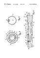
- FIG. 1is a sectional view of a catheter of the present invention with a proximal end and a distal end of the catheter enlarged for clarity.
- FIG. 2is a sectional view of the catheter of FIG. 1 as taken along lines 2 — 2 .
- FIG. 3is a sectional view of the catheter of FIG. 1 as taken along lines 3 — 3 .
- FIG. 4is a sectional view of the catheter of FIG. 1 as taken along lines 4 — 4 .
- FIG. 5is a sectional view of the catheter of FIG. 1 as taken along lines 5 — 5 .
- FIG. 6is an enlarged sectional view of the antenna of the catheter of the present invention.
- FIG. 7is a sectional view of a catheter of the present invention in use in a blood vessel.
- FIG. 8is a sectional view of FIG. 7 taken along lines 8 — 8 .
- FIG. 9Ais a sectional view of an alternate embodiment of the catheter of the present invention.
- FIG. 9Bis a sectional view of an alternate embodiment of the catheter of the present invention.
- FIG. 10Ais a sectional view of an alternate embodiment of the catheter of the present invention shown in FIG. 1 as taken along lines 10 A— 10 A.
- FIG. 10Bis a sectional view of an alternate embodiment of the catheter of the present invention shown in FIG. 1 as taken along lines 10 B— 10 B.
- FIG. 11is a sectional view of an alternate embodiment of a catheter of the present invention.
- FIG. 12is a sectional view of the catheter of FIG. 11 taken along lines 12 — 12 .
- FIG. 13is a sectional view of the catheter of FIG. 11 taken along lines 13 — 13 .
- FIG. 14is a sectional view of the catheter of FIG. 11 taken along lines 14 — 14 .
- FIG. 1shows a side view of catheter 10 including a sectional view of distal end 12 and a plan view of proximal end 14 . Both distal end 12 and proximal end 14 are enlarged relative to catheter shaft 16 for illustrative purposes.
- Catheter 10further includes dilatation balloon 18 , atraumatic tip 19 , microwave antenna 20 , coaxial cable 22 , and manifold 26 .
- Catheter 10is used with guide wire 28 , microwave energy generator 30 , cooling system 32 , and inflation device 34 .
- Guide wire 28includes distal end 36 and proximal end 38 .
- Catheter 10is used in a method of preventing restenosis in which antenna 20 and dilatation balloon 18 are placed across a stenosis in a blood vessel.
- the dilatation balloon 18is used to permanently dilate the stenotic region according to well known angioplasty procedures while antenna 20 is used to apply microwave radiation to kill a medial cell layer of the blood vessel wall to prevent restenosis of the blood vessel.
- Dilatation balloon 18also cools an inner wall surface of the blood vessel in the stenotic region conductively via the inflation fluid, which is either passively or actively cooled via shaft 16 .
- manifold 26 of catheter 10receives coaxial cable 22 (from microwave generating source 30 ), cooling system delivery tubing 40 , guide wire 28 , and inflation device connector 42 for alignment with corresponding lumens within shaft 16 .
- Shaft 16is an extruded multi-lumen, intravascular catheter shaft connected to manifold 26 at proximal shaft end 14 .
- Manifold 26 and shaft 16are preferably made of a suitable polymeric material known to those skilled in the art.
- Shaft 16also includes outer surface 44 .
- shaft 16includes a coating (e.g., TEFLON®) having a low coefficient of friction well known in the art forming outer surface 44 of shaft 16 to facilitate its advancement through a guide catheter positioned within the vascular system.
- Shaft 16has an outer diameter of about 0.1 inches, suitable for insertion within a 10 French size guide catheter.
- Shaft 16is long enough (e.g., 135 centimeters) and of a small enough diameter to permit insertion of distal shaft end 12 through the vascular system and into a coronary blood vessel.
- a proximal portion of shaft 16can be augmented with additional design features well known to those skilled in the art to provide adequate steerability, size, pushability, tracking, and biocompatibility.
- the catheter polymer material forming shaft 16can include a radiopaque filler material well known in the art (e.g., bismuth subcarbonate or barium sulfate) to facilitate visualization of catheter shaft 16 under fluoroscopy.
- catheter shaft 16further includes guide wire lumen 50 , antenna lumen 52 , balloon inflation lumen 54 , outer wall 56 and inner wall 58 .
- Outer wall 56includes inflation port 60 while inflation lumen 54 includes plug 62 and antenna lumen 52 includes plug 63 .
- dilatation balloon 18includes distal waist 64 , proximal waist 66 , and expandable wall portion 68 .
- Guide wire lumen 50extends the full length of catheter shaft 16 and through atraumatic tip 19 and is sized to receive conventional guide wire 28 .
- Inflation lumen 54extends from the catheter proximal end 14 to a point adjacent catheter distal end 12 where lumen 54 is closed by plug 62 .
- Microwave antenna lumen 52is aligned centrally relative to the longitudinal axis of shaft 16 along the length of shaft 16 and at its proximal end, antenna lumen 52 communicates with manifold 26 .
- Antenna lumen 52is adapted for receiving microwave antenna 20 to be permanently positioned within antenna lumen 52 near dilatation balloon 18 so that antenna 20 will be generally situated adjacent a stenosis when shaft 16 is properly positioned within a coronary blood vessel.
- Antenna 20can be bonded within antenna lumen 52 by an adhesive and is carried at the distal-most end of coaxial cable 22 .
- the proximal-most end of coaxial cable 22is connected to microwave generating source 30 .
- Microwave generating source 30produces high frequency microwaves, preferably at about 915 MHz, although other frequencies such as about 2450 MHz can be used.
- antenna 20When antenna 20 is energized by microwave generating source 30 , antenna 20 emits electromagnetic energy which causes selective heating of a medial cell layer within a wall of a blood vessel.
- Dilatation balloon 18cooperates with multi-lumen shaft 16 and is secured about distal end 12 of catheter shaft 16 .
- Distal waist 64 of balloon 18is bonded to shaft exterior surface 44 at distal shaft end 12 while proximal waist 66 of balloon 18 is bonded to shaft outer surface 44 proximal to antenna 20 .
- shaft outer surface 44 and expandable wall portion 68define a chamber which can be inflated (as seen in FIG. 1) and deflated (shown in phantom in FIG. 1) by the selective introduction and removal of an inflation fluid within an interior of expandable wall portion 68 through port 60 of inflation lumen 54 .
- Dilatation balloon 18is provided so that when filled with an inflation fluid, dilatation balloon 18 expands to dilate a stenotic region of the coronary blood vessel.
- Dilatation balloon 18extends for a length adjacent distal shaft end 12 that is substantially less than the length of catheter shaft 16 .
- expandable wall portion 68 of dilatation balloon 18preferably has a length of about 2 to 4 centimeters.
- Dilatation balloon 18is a flexible tubular member formed of PET, cross-linked polyethylene or some other thermoplastic material known to those skilled in the art suitable for dilatation procedures.
- Atraumatic tip 19includes distal end 65 A and proximal end 65 B and has a hollow, flexible resilient body defining a chamber 67 located beyond the distal end 12 of catheter shaft 16 .
- Tip proximal end 65 Bdefines a waist that is adhesively secured on catheter outer surface 44 in an abutting relationship adjacent dilatation balloon distal waist 64 .
- atraumatic tip 19further includes a lumen 69 that acts as an extension of guide wire lumen 50 to permit the passage of guide wire 28 through tip 29 .
- FIG. 2is a sectional view of catheter shaft 16 proximal to dilatation balloon 18 .
- guide wire lumen 50 , antenna lumen 52 , and balloon inflation lumen 54each preferably have a generally circular shaped transverse cross-section.
- Microwave antenna lumen 52preferably has a generally circular shaped transverse cross-sectional area which is substantially larger than a transverse cross-sectional area of any other respective lumen of catheter shaft 16 .
- Antenna lumen 58preferably has a diameter of about 0.060 inches while guide wire lumen 50 preferably has a diameter of about 0.015 inches.
- Balloon inflation lumen 54preferably has a diameter of about 0.012 inches.
- catheter shaft 16further includes cooling lumens 70 and 72 .
- Cooling fluid intake lumen 70 and exhaust lumen 72extend from proximal shaft end 14 to distal shaft end 12 where lumens 70 and 72 terminate and where cooling fluid intake lumen 70 communicates with cooling exhaust lumen 72 .
- Cooling fluid lumens 70 and 72are defined by inner wall 58 and outer wall 56 and preferably have a generally arc shaped transverse cross-section configured to surround antenna lumen 52 .
- Cooling lumens 70 and 72preferably have a uniform radial thickness of about 0.010 inches. In combination, cooling lumens 70 and 72 substantially surround antenna lumen 52 about a substantial majority (about 85%) of a circumference of antenna lumen 52 .
- Cooling lumens 70 and 72surround antenna lumen 52 , so that when filled with a cooling fluid, cooling lumens 70 and 72 cool the catheter shaft outer surface 44 and absorb heat from the artery surface, (which is created by the microwave energy) to protect blood immediately surrounding catheter shaft 16 within a blood vessel.
- FIG. 3is a sectional view of catheter shaft 16 distal to dilatation balloon 18 adjacent catheter distal end 12 .
- balloon inflation lumen 54is sealed shut with plug 62 and antenna lumen 52 is sealed shut with plug 63 .
- This arrangement adjacent catheter distal end 12closes balloon inflation lumen 54 and antenna lumen 52 while cooling lumens 70 and 72 remain open within catheter shaft distal end 12 for communication with each other and guide wire lumen 50 remains open through utmost end of catheter shaft distal end 12 .
- FIG. 4is a sectional view of atraumatic tip 19 distal to utmost catheter distal end 12 .
- tip 19defines chamber 67 and guide wire lumen extension 69 .
- Guide wire lumen extension 69permits the passage of guide wire 28 through atraumatic tip 19 .
- Chamber 67provides a common area for communication between cooling lumens 70 and 72 distal to utmost catheter distal end 12 to facilitate circulation of cooling fluid from cooling intake lumen 70 into cooling exhaust lumen 72 .
- cooling intake lumens 70 and cooling exhaust lumens 72cooperate with cooling system 32 (via manifold 26 as shown in FIG. 1) to provide a selectively controlled flow of fluid through cooling lumens 70 and 72 during a treatment session.
- intake lumen 70is supplied with deionized water from cooling system 32 .
- Water from cooling system 32is chilled to about 8° C. and pumped through cooling fluid intake lumen 70 toward distal shaft end 12 .
- Under fluid pressurewater enters cooling fluid exhaust lumen 72 via chamber 67 of atraumatic tip 19 and returns to cooling system 32 through exhaust lumen 72 for re-chilling and re-circulation.
- Cooling system 32is capable of circulating fluid at a high speed rate to maintain fluid with shaft 16 at a relative low temperature (e.g., 8° C.).
- FIG. 5is a sectional view of catheter shaft 16 and dilatation balloon 18 .
- expandable wall 68 of balloon 18is arranged concentrically about catheter shaft 16 to surround catheter shaft outer surface 44 and cooling lumens 70 and 72 .
- Balloon inflation lumen 54communicates with an interior of dilatation balloon 18 via inflation port 60 .
- Dilatation balloon 18is inflated by inflation device 34 (FIG. 1) which selectively supplies inflation fluid to balloon 18 through lumen 54 under pressure sufficient to dilate a stenotic region of a blood vessel. Accordingly, selective inflation and deflation of dilatation balloon 18 permits the selective dilatation of a blood vessel to perform the well known PTCA procedure.
- expandable portion 68preferably has a generally circular shaped transverse cross-section when inflated.
- Dilatation balloon 18has a wall thickness of about 0.0005 to 0.005 inches, preferably having a thickness of 0.005 inches. When inflated, dilatation balloon 18 has a predetermined diameter selected in the range of about 2.5 to 6.5 millimeters.
- outer wall 56 defining cooling lumens 70 and 72has a thickness and strength sufficient to maintain the arcuate shape of the cooling lumens 70 and 72 should pressure within the dilatation balloon exceed fluid pressures in the cooling lumens 70 and 72 .
- cooling fluid passing through cooling lumens 70 and 72passively cools (via conduction) inflation fluid within dilatation balloon 18 and inflation lumen 54 .
- Passive cooling of the balloon inflation fluidpermits the expandable wall 68 of the balloon 30 to cool an inner surface wall of a blood vessel when the dilatation balloon 18 presses against the vessel inner wall surface during dilatation of the vessel wall.
- the passive cooling provided by cooling fluid circulating in cooling lumens 70 and 72effectively converts the balloon inflation fluid and dilatation balloon 18 into a cooling chamber to cool the surrounding blood vessel wall surface.
- FIG. 6illustrates in detail the microwave antenna 20 used in the present invention to radiate the medial cell layer of a stenotic region of a blood vessel wall.
- Antenna 20is designed so that an outer diameter of antenna 20 is no greater than an outer diameter of coaxial cable 22 , and so that antenna 20 is relatively short, e.g., about 2-3 centimeters.
- microwave antenna 20is positioned within microwave antenna lumen 52 and is surrounded by cooling lumens 70 and 72 and dilatation balloon 18 .
- FIG. 6illustrates a sectional view of microwave antenna 20 along its length.
- Antenna 20is positioned at the distal most end of shielded coaxial cable 22 .
- Cable 22is a standard miniature 30 AWG or 32 AWG coaxial cable and can be obtained from CoonerWire of Chatsworth, Calif.
- Coaxial cable 22includes inner conductor 100 , inner insulator 102 , outer conductor 104 , and outer insulator 106 .
- Antenna 20further includes transition portion 108 , reduced diameter portion 110 of inner insulator 102 , first tubular extension 112 , second tubular extension 114 , and annular collar 116 .
- Antenna 20also includes a flat wire coil 118 , capacitor 120 , solder 122 , and end cap 124 .
- First tubular extension 112encompasses outer conductor 104 and reduced diameter portion 110 of inner insulator 102 .
- a proximal end of tubular extension 112is positioned adjacent transition portion 108 of cable 22 .
- Annular collar 116also encompasses outer conductor 104 and reduced diameter portion 110 of inner insulator 102 and abuts a distal end of tubular extension 112 .
- Annular collar 116is a conductive material that is in electrical contact with outer conductor 104 and wire coil 118 .
- Second tubular extension 114also encompasses outer conductor 104 and reduced diameter portion 110 of inner insulator 102 with a proximal end of second tubular extension 114 abutting annular collar 116 .
- a distal end of second tubular extension 114has end cap 124 disposed therein.
- Flat wire 118forms a coil about tubular extensions 112 and 114 .
- Capacitor 120is secured about a distal end of inner conductor 100 and is further electrically connected to flat wire coil 118 by solder 122 extending through hole 126 .
- Reduced diameter portion 110preferably has an outer diameter of about 0.05 inches.
- Tubular extensions 112 and 114have lengths of 1 inches and 0.8 inches, respectively, and can have a thickness of about 0.005 inches.
- Reduced diameter portion 110 and tubular extensions 112 and 114have outer diameters (or thicknesses) of a size so that when antenna 20 is fully constructed, antenna 20 has an outer diameter of about 0.060 inches or less.
- Antenna 20includes a first coil section 140 and a second coil section 142 , both of which are of equal length. These two sections are created by the electrical connection of annular collar 116 with flat wire coil 118 at a midsection of flat wire coil 118 .
- first and second coil sections 140 and 142are each comprised of five equally-spaced windings of flat wire coil 118 about tubular extensions 112 and 114 , respectively.
- the combined length of first and second coil sections 140 and 142provide an overall length of antenna 20 of about 2 centimeters. However, this overall length and the number of windings of the coil can be varied as needed to provide the desired length of antenna coil 118 .
- flat wire 118is made of a flat ribbon of copper or silver and can be plated with a highly conductive material.
- the ribboncan be 0.02 inches wide and 0.006 inches thick.
- Flat wire 118has a physical length of 4.5 inches, which when coiled provides a total length for first coil wire section 140 and second coil wire section 142 of 2 centimeters.
- the location along coil 118 of an electrical connection between first coil section 140 and capacitor 120corresponds to a tap point used for impedance matching.
- a tap pointis selected along coil 118 so that an impedance presented between the tap point and annular collar 116 (corresponding to the point of electrical connection between coil 118 and inner conductor 100 ) matches the characteristic impedance of coaxial cable 22 .
- the tap pointis located adjacent the end of first coil section 140 of coil 118 .
- the tap pointcan be located nearer to annular collar 116 as necessary to obtain the required impedance match.
- first coil section 140 or second coil section 142also includes an inductive component which is eliminated by providing a series capacitance such as capacitor 120 .
- tubular capacitor 120serves to counteract a reactive component of antenna 34 , thereby providing a fifty (50) Ohm resistive impedance match between coaxial cable 22 , microwave generating source 30 , and antenna 20 .
- Tubular capacitor 120preferably has a value of about 2.7 pF and can be obtained from Coors Ceramics Co. of Golden, Colo.
- Capacitor 120preferably is sized to fit over an inner conductor 100 and has a length of 0.125 inches, an outer diameter of about 0.045 inches, and an inner diameter of about 0.025 inches.
- Tubular capacitor 120is substantially similar in design to a tubular capacitor described and shown in Rudie et al. U.S. Pat. No. 5,370,677, which is hereby incorporated by reference, and is mounted and connected to the inner conductor 100 and flat wire antenna coil 118 in a manner substantially similar to that described in Rudie et al. U.S. Pat. No. 5,370,677.
- ⁇ ris the relative dielectric constant of the inner insulator 102
- Dis the inner diameter of outer conductor 104
- dis the outer diameter of inner conductor 100 .
- a characteristic impedance of 50 Ohmscan be maintained with a reduced diameter portion 110 by adjusting the ratio of D/d (e.g., reducing d), by selecting an appropriate relative dielectric constant ( ⁇ r ), or by adjusting both the ratio D/d and the relative dielectric constant ( ⁇ r ).
- any resulting impedance mismatch resulting from the altered diameter of reduced diameter portion 110 of inner insulator 102can be remedied by selecting an appropriate tap point location and a corresponding capacitor value for capacitor 120 .
- antenna 20can include platinum or gold bands located adjacent either or both ends of the flat wire antenna coil 118 to facilitate positioning of antenna 20 and catheter 10 within the cardiovascular system since the gold bands will substantially improve visualization of antenna 20 under fluoroscopy.
- Antenna 20generally has a helical dipole construction similar to the helical dipole construction of a microwave antenna described and shown in Rudie et al., U.S. Pat. Nos. 5,300,099 and 5,370,677, which are hereby incorporated by reference. Accordingly, the helical dipole construction of antenna 20 of the present invention has an effective electrical length generally equal to one-half of the wave length of the radiation emitted in the surrounding medium, e.g., the catheter shaft and surrounding tissue. Because of the helical dipole construction of antenna 20 , in accordance with Rudie U.S. Pat. Nos. 5,300,099 and 5,370,677, antenna 20 can have different physical lengths yet have the same effective electrical length to produce a consistent and predictable pattern of radiation.
- FIGS. 7 and 8show enlarged sectional views of a blood vessel 150 with catheter 10 properly positioned within blood vessel 150 .
- Blood vessel 150includes intima 152 , internal elastic laminate 154 , medial layer 156 , adventitia 158 , and stenotic region 160 .
- Stenotic region 160includes plaque and other deposits formed along intima 152 as is well known in the art. Accordingly, FIGS. 7 and 8 omit an illustration of the plaque for clarity sake in illustrating the catheter 10 and major vessel components.
- catheter 10is inserted into the guide catheter from outside the body at a remote location (e.g., femoral artery).
- the catheter 10is advanced through the cardiovascular system until dilatation balloon 18 of catheter 10 is maneuvered across stenotic region 160 in its deflated state and is then inflated as shown to dilate stenotic region 160 .
- the expandable wall 68presses against intima 152 with sufficient pressure to seal off stenotic region 160 from blood circulating in blood vessel 150 and with sufficient pressure to break internal elastic laminate 154 to permanently dilate stenotic region 160 in accordance with well known angioplasty techniques.
- microwave antenna 20is energized by microwave generating source 30 which causes antenna 20 to radiate microwaves at 902-928 MHz frequency.
- the microwave radiationis applied at a power (e.g. 25 watts) and for a time sufficient to cause the medial cell layer 156 to be heated inductively and to be substantially destroyed.
- the volume of tissue including the medial cell layer 156is heated according to a time and temperature relationship which substantially destroys the medial cell layer 156 .
- the period of time and power level appliedare manipulated to achieve heating above 45° C. to a select depth sufficient to destroy the medial cell layer 156 .
- cooling fluid circulating within the cooling lumens 70 and 72passively cools the balloon inflation fluid within dilatation balloon 18 to thereby cool intima 152 in stenotic region 160 (via balloon expandable wall portion 68 ) and prevent substantial damage to intima 152 .
- cooling fluid in cooling lumens 70 and 72cools the blood circulating within blood vessel 150 to prevent the blood from coagulating and prevent thrombotic activity from occurring on the intima 152 of vessel 150 .
- This heating pattern created by catheter 10allows greater temperature elevation (caused by microwave energy) to be concentrated primarily at medial cell layer 156 within the blood vessel 150 while intima 152 is protected from necrosing temperatures (e.g., above 45° C.).
- the dilatation balloon 18can be deflated and the microwave antenna 20 de-energized. Once the dilatation balloon 18 is deflated, the catheter 10 can be removed from blood vessel 150 proximally through the cardiovascular system as is well known in the art.
- the catheter of the present inventionpermits the application of microwave energy in a blood vessel to ablate a medial cell layer of stenotic region of a blood vessel.
- This capabilityis achieved by a combination of features including, amongst others, an efficient dipole helical antenna design and a cooling system.
- the cooling systemincludes a pair of cooling lumens and a dilatation balloon. Inflation fluid within the dilatation balloon is passively cooled by cooling fluid circulating through the cooling lumens adjacent the dilatation balloon.
- This passively cooled balloon inflation fluid within dilatation balloon 18cools intima 152 via thermal conduction (when microwave antenna 20 within antenna lumen 52 is energized) so that the temperature of intima 152 immediately adjacent balloon 18 , and intima 152 just distal and proximal to balloon 18 will remain below a necrosing temperature as desired (e.g., below 45° C.).
- This cooling systemacts in cooperation with the microwave radiation emitted by antenna 20 to substantially reduce or prevent significant restenosis by achieving several effects simultaneously.
- the microwave radiationkills the medial cell layer of the blood vessel in the stenotic region to reduce smooth muscle cell proliferation associated with restenosis after the PTCA.
- dilatation of the blood vessel in the stenotic region during the application of microwave radiationeffectively blocks exposure of circulating blood to the damaged tissue being radiated until after the medial cell layer is killed. This sealing action impedes blood borne stimuli from stimulating a smooth muscle cell proliferation response or thrombotic/coagulative response (associated with restenosis) while the medial cell layer is exposed to circulating blood.
- cooling both blood circulating in the blood vessel and intima 152(via the cooling lumens and the dilatation balloon) prevents thrombotic and coagulative action in the blood.
- FIGS. 9A, 9 Bshow alternative embodiments of catheter 10 of the present invention.
- the structure of catheter 10is substantially identical to the structure shown in FIGS. 1-8 except for replacing guide wire lumen 50 with guide wire lumen 200 (FIG. 9A) and guide wire lumen 210 (FIG. 9 B), respectively.
- Guide wire lumen 200is identical to guide wire lumen 50 except for an expanded region adjacent dilatation balloon 18 to permit perfusion.
- Guide wire lumen 200includes distal port 202 , proximal port 204 , and expanded diameter portion 206 .
- Guide wire lumen 200 of catheter 10is used with guide wire 28 in a manner well known in as described in association with FIGS. 1-8.
- Expanded portion 206communicates with lumen 69 of atraumatic tip 19 to permit the passage of guide wire 28 and has a diameter sufficient to permit blood to pass therethrough with guide wire 28 also extending therethrough.
- blood circulating in blood vessel 150is permitted to pass into proximal port 204 of guide wire lumen 200 , through expanded portion 206 , and out distal port 202 into the blood vessel 150 .
- This expanded guide wire lumen 200permits catheter 10 to perfuse blood past stenotic region 160 during a dilatation procedure, which would otherwise completely block the passage of blood through the stenotic region 160 .
- perfusion through guide wire lumen 200can be accomplished without removing guide wire 28 from its position in blood vessel 150 . This perfusion feature permits longer dilatation procedures, and more significantly, permits longer application of microwave radiation to the medial cell layer during dilatation to insure that the medical cell layer is substantially destroyed to ultimately reduce restenosis.
- guide wire lumen 210also replaces guide wire lumen 50 of catheter 10 , which is completely eliminated from catheter shaft 16 .
- Guide wire lumen 210includes distal port 212 , proximal port 214 , and mid portion 216 .
- Mid portion 216has a diameter sufficient to permit perfusion of blood therethrough.
- guide wire 28is placed in blood vessel 150 so that its distal end lies across stenotic region 160 .
- the guide wire lumen 210 of catheter 10is advanced onto guide wire 28 by guiding distal port 212 onto and over proximal end 38 of guide wire 28 until the guide wire proximal end 38 exits guide wire lumen proximal port 214 .
- the catheter 10is then advanced over guide wire 28 until dilatation balloon 18 is positioned across stenotic region 160 .
- the combined dilatation and radiation stepsare then performed as previously described in association with FIGS. 1-8.
- guide wire lumen 210permits blood to pass from blood vessel 150 on the proximal side of stenosis 160 into proximal port 214 , through portion 216 , and out distal port 212 for further circulation in blood vessel 150 on a distal side of stenosis 160 .
- FIGS. 10A and 10Billustrate another alternate embodiment of catheter 10 of the present invention in which dilatation balloon 18 is inflated by cooling fluid that circulates through cooling lumens 70 and 72 .
- FIG. 10Ais a sectional view of alternate embodiment catheter shaft 16 proximal to dilatation balloon 18 . As shown in FIG. 10A, catheter shaft 16 no longer includes balloon inflation lumen 54 .
- FIG. 10Bis a sectional view of this alternate embodiment catheter 10 at dilatation balloon 18 . As shown, holes 220 A and 220 B are formed in outer wall 56 . Hole 220 A permits communication between cooling intake lumen 70 and an interior of dilatation balloon 18 while hole 220 B permits communication between cooling exhaust lumen 72 and an interior of dilatation balloon 18 .
- cooling fluidpasses out of cooling lumen 70 through hole 220 A into the interior of dilatation balloon 18 where it circulates before passing out of the balloon interior into cooling exhaust lumen 72 through hole 220 B.
- Cooling fluidis supplied under a pressure sufficient to inflate balloon to dilate the stenotic region 160 and at a rate of circulation sufficient to maintain the cool temperature of the fluid.
- the cooling fluidboth inflates dilatation balloon 18 and actively cools dilatation balloon 18 to place circulating cooling fluid immediately adjacent the blood vessel wall during the dilatation procedure.
- a cooling and pressurization systemas discussed in association with FIGS. 11-14 can be used to supply adequate circulation and pressure to both inflate and cool dilatation balloon 18 .
- FIGS. 11-14Another embodiment of a catheter of the present invention is illustrated in FIGS. 11-14 in which a dilatation balloon is inflated and actively cooled by a single cooled fluid supplied through the catheter shaft.
- Catheter 250 shown in FIG. 11is used in a method of preventing restenosis like catheter 10 (shown in FIGS. 1 - 8 ).
- Catheter 250includes distal end 252 , proximal ends 254 , and multi-lumen shaft 256 .
- FIG. 11shows a side view of catheter 250 including a sectional view of distal end 252 and a plan view of proximal end 254 . Both distal end 252 and proximal end 254 are enlarged relative to shaft 256 of catheter 250 for illustrative purposes.
- Catheter 250further includes dilatation balloon 258 , atraumatic tip 257 , microwave antenna 260 , coaxial cable 262 , and manifold 266 .
- Catheter 250is used with guide wire 268 , microwave energy generator 270 , and cooling and pressurization system 272 .
- Guide wire 278includes distal end 288 and proximal end 290 .
- Manifold 266receives coaxial cable 262 (from microwave generating source 270 ), cooling and pressurization system inlet 284 and outlet 282 , and guide wire 28 for alignment with corresponding lumens within shaft 256 .
- Manifold 266includes an inlet 283 for communicating with cooling and pressurization system outlet 282 and an outlet 285 for communicating with cooling and pressurization system inlet 284 .
- Shaft 256is an extruded multi- lumen, intravascular catheter shaft connected to manifold 266 of proximal shaft end 14 .
- Multi-lumen shaft 256has attributes and features similar to shaft 16 of catheter 10 .
- Shaft 256is made of a suitable polymeric material, has an outer surface 292 , and is coated and sized appropriately to permit use in a cardiovascular system as previously disclosed with regard to shaft 16 of catheter 10 .
- catheter shaft 256further includes guide wire lumen 300 and balloon inflation chamber 302 .
- dilatation balloon 258further includes distal end 304 , proximal end 306 , and expandable wall portion 308 .
- Tip 257includes distal end 309 , body 310 , and guide wire lumen extension 312 , and proximal waist 311 . Except for guide wire lumen 300 , plug 313 and antenna terminal portion 314 define catheter shaft distal end 252 and define a distal end of balloon inflation chamber 302 .
- Guide wire lumen 300extends the full length of catheter shaft 256 and tip 257 and is sized to receive conventional guide wire 268 .
- Balloon inflation chamber 302generally extends from a proximal end of plug 313 to a point adjacent balloon proximal waist 306 .
- Chamber 302has an outer wall defined by expandable wall 308 , and inner wall defined by guide wire lumen 300 and antenna 260 .
- antenna 260 and coaxial cable 262are aligned centrally relative to the longitudinal axis of shaft 256 along the length of the distal end 252 .
- Antenna 260is fixed in this position with antenna terminal portion 312 being fixed in plug 313 at shaft distal end 252 .
- Antenna 260is arranged in shaft 256 relative to dilatation balloon 258 to be generally situated adjacent a stenosis when shaft 256 is properly positioned within a coronary blood vessel.
- Antenna 260is carried at the distal-most end of coaxial cable 262 while the proximal-most end of coaxial cable 262 is connected to microwave generating source 270 .
- Microwave generating source 270produces high frequency microwaves, preferably at about 915 MHz.
- antenna 260is energized by microwave generating source 270 , antenna 260 emits electromagnetic energy which causes heating of tissue within a coronary blood vessel.
- Microwave antenna 260includes microwave antenna 20 as previously described and as illustrated in FIG. 6, or alternatively includes a helical dipole microwave antenna described and shown in Rudie et al. U.S. Pat. Nos. 5,300,099 and 5,370,677, both of which are hereby incorporated by reference.
- antenna 20is preferably coated with insulation (e.g., parylene) to insure insulation from cooling fluid circulating about antenna 260 .
- insulatione.g., parylene
- antenna 260can be further insulated with polytetrafluoroethylene or another high temperature polymer material.
- dilatation balloon 258cooperates with its multi-lumen shaft 256 and is secured about distal end 252 of catheter shaft 256 by bonding of distal waist 304 and proximal waist 306 to shaft outer surface 292 .
- Dilatation balloon 258can be inflated (as seen in FIG. 11) and deflated (shown in phantom in FIG. 11) by the selective introduction and removal of an inflation fluid within an interior of balloon inflation chamber 302 via multi-lumen catheter shaft 256 . When filled with an inflation fluid under pressure, dilatation balloon 258 expands to permanently dilate a stenotic region of a coronary blood vessel.
- cooling and pressurization system 272includes heat exchanger 274 , pump 276 , reservoir 278 , and pressurization device 280 .
- Connectors 286permit communication between the respective elements of the cooling and pressurization system 272 .
- Cooling and pressurization system 272is connected to manifold 266 for communication with corresponding lumens in multi-lumen shaft 256 .
- System outlet 282permits communication from heat exchanger 274 to cooling intake lumen 70 (via manifold 266 ) and system outlet 284 permits communication from cooling exhaust lumen 72 (via manifold 266 ) to reservoir 278 .
- the cooling and pressurization system 272is used in cooperation with multi-lumen shaft 256 to provide a liquid that is under pressure for inflating dilatation balloon 258 and that is chilled to provide cooling within dilatation balloon 258 .
- the inlet 284 and outlet 282 of cooling and pressurization system 272are also selectively controllable to cause a pressure differential between inlet 284 and outlet 282 to control the inflation and deflation of dilatation balloon 258 via cooling fluid intake and exhaust lumens 320 and 322 in catheter shaft 256 .
- Reservoir 278contains the bulk of the fluid that circulates through multi-lumen shaft 256 and dilatation balloon 258 .
- the reservoirincludes a means for removing all air from the fluid circulating with catheter 250 .
- Pressurization device 280is provided to pressurize fluid within the cooling and pressurization system 272 to permit selective inflation of dilatation balloon 258 . While pressurization device 280 is shown connected to reservoir 278 , pressurization device 280 can be connected to pump 276 instead of reservoir 278 . In addition, pressurization device could alternatively be connected directly to system inlet 284 and take the form of a conventional PTCA inflation device.
- Pump 276is capable of circulating fluid within system 272 , catheter shaft 256 and dilatation balloon 258 at an operating pressure sufficient to inflate dilatation balloon 258 to perform dilatation angioplasty on a stenotic region of a coronary blood vessel.
- Pump 276preferably is a peristaltic-type pump or other suitable pump known to those skilled in the art.
- Heat exchanger 274is capable of transferring sufficient heat from the circulating inflation/coolant fluid to maintain a desired coolant temperature (e.g., 8° C.) as the coolant flows through the multi-lumen shaft 256 and dilatation balloon 258 .
- FIG. 12is a sectional view of catheter shaft 256 proximal to dilatation balloon 258 .
- guide wire lumen 300preferably has a generally circular shaped transverse cross-section.
- catheter shaft 256further includes cooling intake lumen 320 and cooling exhaust lumen 322 , inner wall 324 , outer wall 326 , and guide wire lumen wall 328 .
- Cooling fluid intake lumen 320 and exhaust lumen 322extend from proximal shaft end 254 to distal shaft end 252 where lumens 320 and 322 terminate proximal to expandable wall portion 308 of dilatation balloon 258 (FIG. 11 ).
- Cooling lumens 320 and 322are defined by inner wall 324 and outer wall 326 and preferably have a generally semi-circle shaped transverse cross-section with cooling lumen 322 configured to receive coaxial cable 262 , which has a generally circular transverse cross section. When filled with cooling fluid from cooling and pressurization system 272 , cooling lumens 320 and 322 provide cooling to protect blood circulating within a blood vessel immediately surrounding catheter shaft 256 . Cooling fluid intake lumen 320 communicates with cooling exhaust lumen 322 near distal shaft end 252 within balloon inflation chamber 302 (defined by dilatation balloon 258 ).
- FIG. 13is a sectional view of catheter 250 at dilatation balloon 258 .
- expandable wall 308 of dilatation balloon 258is arranged concentrically about coaxial cable 262 and guide wire lumen 300 (defined by guide wire lumen wall 328 ).
- outer wall 326 and inner wall 324 defining cooling lumens 320 and 322has been removed so that guide wire lumen 300 and coaxial cable 262 (including antenna 260 ) are the only structures defining inner walls of balloon inflation chamber 302 .
- Expandable wall 308defines the outer wall of balloon inflation chamber 302 .
- Guide wire lumen 300is fixed in place at its distal end by its securement against catheter shaft outer wall 326 adjacent balloon distal waist 304 , and is secured in place at its proximal end against outer wall 326 , adjacent balloon proximal waist 306 .
- coaxial cable 262(including antenna 260 ) is fixed within shaft 256 at the distal end by terminal portion 314 being lodged in plug 313 (FIG. 11 ).
- antenna terminal portion 314is fixed within plug 313 which completely fills and blocks an interior of catheter shaft 256 except for guide wire lumen 300 which extends the full length of catheter shaft 256 .
- the proximal portion of coaxial cable 262proximal to antenna 260 floats freely within lumen 322 .
- Cooling fluid cooled and supplied under pressure from cooling and pressurization system 272enters chamber 302 from cooling intake lumen 320 , and after circulating in chamber 302 , exits into cooling exhaust lumen 322 . Cooling fluid is supplied under a pressure sufficient to permanently dilate a stenotic region of a blood vessel upon inflation of dilatation balloon 258 .
- Catheter 250is used in a method of preventing restenosis similar to that described for catheter 10 with regard to FIGS. 1-8. However, with catheter 250 , cooling lumens 320 and 322 communicate directly with balloon inflation chamber 302 . Fluid circulating within multi-lumen catheter shaft 256 (for cooling blood about catheter shaft outer surface 292 ) also circulates directly within dilatation balloon wall 308 and is used to both cool dilatation balloon wall 308 and to inflate dilatation balloon wall 308 in a manner sufficient to permanently dilate a stenotic region of a coronary blood vessel.
- the fluidalso circulates under a pressure sufficient to effect permanent dilation of a stenotic region of any coronary blood vessel by virtue of pressurization device 280 of the cooling and pressurization system 272 while heat exchanger 274 acts to insure that fluid circulating within dilatation balloon 258 is at a temperature sufficient to cool intima 152 to protect intima from heat damage from energy radiated by microwave antenna 260 .
- catheter 250is inserted and advanced in the cardiovascular system until the dilatation balloon 258 (in its deflated state) is placed across stenotic region 160 of blood vessel 150 .
- Activation of cooling and pressurization system 272causes circulation of cooling fluid through cooling lumens 320 and 322 to cool catheter shaft 256 and dilatation balloon 258 while simultaneously causing expandable wall 308 to expand outwardly and dilate the stenotic region.
- microwave antenna 260is activated to radiate microwave radiation into the blood vessel wall 150 to kill medial cell layer 156 while cooling/inflation fluid within dilatation balloon 258 protects intima 152 .
- dilatation balloon 258can be deflated and the microwave antenna 260 de-energized. Once the dilatation balloon 258 is deflated, the catheter 250 can be removed from blood vessel 150 proximally through the cardiovascular system.
- a method using catheter 250prevents restenosis of a stenotic region 160 of a blood vessel 150 by radiating microwave energy from microwave antenna 260 to kill medial cell layer 156 in the stenotic region 160 . Radiation is applied during inflation of dilatation balloon 258 , which permanently dilates the stenotic region. Killing the medial cell layer 156 prevents smooth muscle cell proliferation, which is believed to be a primary factor in restenosis.
- the expandable wall 308 of dilatation balloon 258forms a seal against an inner wall surface of blood vessel 150 to exclude blood in vessel 150 from contacting the stenotic region 160 during the dilatation procedure.
- This sealing actionprevents a potential triggering of medial smooth cell proliferation, inflammatory response or thrombotic action in the blood vessels associated with restenosis.
- Fluid circulating within cooling lumens 320 and 322 in catheter shaft 256cools blood circulating within blood vessel 150 to prevent the blood from coagulating during the application of radiation to stenotic region 160 .
- the cooling fluidwhich is also used to inflate dilatation balloon 258 , cools an inner surface wall of blood vessel in a stenotic region conductively via dilatation balloon expandable wall 308 .
- catheter 10 shown in FIGS. 9A and 9Bwhich includes expanded guide wire lumen 200 and 210 , respectively
- catheter 250can be implemented in catheter 250 by similarly providing an expanded guide wire lumen in the region of dilatation balloon 258 .
- the method of the present invention using catheter 10 or catheter 250acts in at least three ways to prevent restenosis after a balloon dilatation angioplasty procedure by neutralizing several factors associated with restenosis.
- application of microwave radiationkills the medial cell layer, which is associated with smooth muscle cell proliferation.
- the methodpreferably excludes blood from the stenotic region until after the medial cell layer is destroyed since exposure of circulating blood to the medial cell layers is also associated with restenosis.
- cooling actionprevents coagulation of blood circulating in the blood vessel and prevents thrombotic action along the vessel wall in the stenotic region, both of which are associated with restenosis and other health risks.
- catheter 10 and catheter 250have been described for use as a primary angioplasty PTCA dilatation catheter for permanently dilating a stenotic region along with applying radiation to kill a medial cell layer of a blood vessel to prevent restenosis
- catheter 10 and catheter 250can be used secondarily after a PTCA procedure has already been performed to permanently dilate a stenotic region of a blood vessel.
- the conventional PTCA procedureis performed using a conventional angioplasty dilatation balloon catheter.
- the dilatation balloon catheteris removed and catheter 10 or catheter 250 of the present invention is inserted and advanced until dilatation balloon 18 or dilatation balloon 258 lies across the stenotic region.
- the respective dilatation balloon ( 18 , 258 ) of catheters 10 and 250is then inflated sufficiently to establish wall contact with blood vessel 150 for creating a seal against intima 152 of blood vessel 150 to exclude blood circulating within blood vessel 150 from being further exposed to disruption of the inner wall surface of blood vessel 150 (including possible exposure to medial cell layer 156 ).
- radiationis applied with the microwave antenna ( 20 or 260 ) to kill the medial cell layer of the stenotic region of the blood vessel.
- catheter 10 and catheter 250can be removed as previously described.
- the method of preventing restenosis with catheter 10 or catheter 250 in which catheter 10 or catheter 250 is used as a primary PTCA catheter for performing the dilatation stepis preferred since the radiation step occurs simultaneously with the dilatation step. This excludes blood from the stenotic region until after the medial cell layer has been killed by radiation from the microwave antenna. This relationship may be important since it is believed that exposure of circulating blood to a medial cell layer may be strongly associated with smooth muscle cell proliferation and the accompanying restenosis.
Landscapes
- Health & Medical Sciences (AREA)
- Life Sciences & Earth Sciences (AREA)
- Engineering & Computer Science (AREA)
- Surgery (AREA)
- Biomedical Technology (AREA)
- Veterinary Medicine (AREA)
- Nuclear Medicine, Radiotherapy & Molecular Imaging (AREA)
- Animal Behavior & Ethology (AREA)
- General Health & Medical Sciences (AREA)
- Public Health (AREA)
- Heart & Thoracic Surgery (AREA)
- Physics & Mathematics (AREA)
- Otolaryngology (AREA)
- Medical Informatics (AREA)
- Molecular Biology (AREA)
- Electromagnetism (AREA)
- Radiology & Medical Imaging (AREA)
- Pathology (AREA)
- Cardiology (AREA)
- Plasma & Fusion (AREA)
- Media Introduction/Drainage Providing Device (AREA)
Abstract
Description

Claims (16)
Priority Applications (4)
| Application Number | Priority Date | Filing Date | Title |
|---|---|---|---|
| US08/852,154US6223085B1 (en) | 1997-05-06 | 1997-05-06 | Device and method for preventing restenosis |
| PCT/US1998/007053WO1998049933A1 (en) | 1997-05-06 | 1998-04-09 | Device and method for preventing restenosis |
| EP98914624.6AEP0994670B1 (en) | 1997-05-06 | 1998-04-09 | Device for preventing restenosis |
| AU68936/98AAU6893698A (en) | 1997-05-06 | 1998-04-09 | Device and method for preventing restenosis |
Applications Claiming Priority (1)
| Application Number | Priority Date | Filing Date | Title |
|---|---|---|---|
| US08/852,154US6223085B1 (en) | 1997-05-06 | 1997-05-06 | Device and method for preventing restenosis |
Publications (1)
| Publication Number | Publication Date |
|---|---|
| US6223085B1true US6223085B1 (en) | 2001-04-24 |
Family
ID=25312607
Family Applications (1)
| Application Number | Title | Priority Date | Filing Date |
|---|---|---|---|
| US08/852,154Expired - LifetimeUS6223085B1 (en) | 1997-05-06 | 1997-05-06 | Device and method for preventing restenosis |
Country Status (4)
| Country | Link |
|---|---|
| US (1) | US6223085B1 (en) |
| EP (1) | EP0994670B1 (en) |
| AU (1) | AU6893698A (en) |
| WO (1) | WO1998049933A1 (en) |
Cited By (118)
| Publication number | Priority date | Publication date | Assignee | Title |
|---|---|---|---|---|
| US6584361B1 (en)* | 1999-05-07 | 2003-06-24 | Prostalund Operations Ab | Method and device for heat treatment of body tissue |
| US20030195595A1 (en)* | 2001-11-05 | 2003-10-16 | Magnus Bolmsjo | Thermotherapy catheter and method of prostate thermotherapy with improved guide and heat confinement |
| US6652491B1 (en)* | 2001-05-03 | 2003-11-25 | Catheter Research, Inc. | Steerable stylet |
| US20040148004A1 (en)* | 2001-02-09 | 2004-07-29 | Wallsten Hans Ivar | Balloon catheter and method for treatment of a mammalian duct or cavity by pressure or heat |
| US20040167467A1 (en)* | 2003-02-21 | 2004-08-26 | Kent Harrison | Delivering cooled fluid to sites inside the body |
| US20040243119A1 (en)* | 1999-08-23 | 2004-12-02 | Cryocath Technologies Inc. | Endovascular cryotreatment catheter |
| US20040267338A1 (en)* | 2003-06-25 | 2004-12-30 | Kent Harrison | Targeted tissue cooling within a body |
| US20050107741A1 (en)* | 2003-11-18 | 2005-05-19 | Martin Willard | Targeted cooling of tissue within a body |
| EP1547536A1 (en)* | 2003-12-26 | 2005-06-29 | Keio University | Balloon catheter, medical apparatus and method for treating living organ |
| US20050245920A1 (en)* | 2004-04-30 | 2005-11-03 | Vitullo Jeffrey M | Cell necrosis apparatus with cooled microwave antenna |
| US20050261626A1 (en)* | 2004-05-21 | 2005-11-24 | Keio University | Balloon catheter, medical apparatus and method for treating living organ |
| US20060025840A1 (en)* | 2004-08-02 | 2006-02-02 | Martin Willard | Cooling tissue inside the body |
| US20070016180A1 (en)* | 2004-04-29 | 2007-01-18 | Lee Fred T Jr | Microwave surgical device |
| US20070049918A1 (en)* | 2005-08-24 | 2007-03-01 | Van Der Weide Daniel W | Microwave device for vascular ablation |
| US20070203551A1 (en)* | 2005-07-01 | 2007-08-30 | Microsulis Limited | Radiation applicator and method of radiating tissue |
| US20070288079A1 (en)* | 2006-03-24 | 2007-12-13 | Micrablate | Energy delivery system and uses thereof |
| US20080039790A1 (en)* | 2003-12-26 | 2008-02-14 | Nihon Medix Co., Ltd. | Heating Type Balloon Catheter Device, and Elastic Tube Device and Vibrator Device for the Catheter Device |
| US20080119921A1 (en)* | 2004-04-29 | 2008-05-22 | Micrablate | Air-core microwave ablation antennas |
| US20080147056A1 (en)* | 2006-07-14 | 2008-06-19 | Micrablate | Energy delivery systems and uses thereof |
| USRE40472E1 (en) | 1998-07-28 | 2008-08-26 | Prostalund Operations Ab | Method and device for combined heat treatment of body tissue |
| US20080275436A1 (en)* | 2004-07-02 | 2008-11-06 | Nigel Cronin | Radiation Applicator and Method of Radiating Tissue |
| US7467015B2 (en) | 2004-04-29 | 2008-12-16 | Neuwave Medical, Inc. | Segmented catheter for tissue ablation |
| US20090112196A1 (en)* | 2007-10-31 | 2009-04-30 | Illuminoss Medical, Inc. | Light Source |
| US20100256641A1 (en)* | 2007-12-26 | 2010-10-07 | Illuminoss Medical, Inc. | Apparatus and Methods for Repairing Craniomaxillofacial Bones Using Customized Bone Plates |
| US20100262188A1 (en)* | 2009-04-07 | 2010-10-14 | Illuminoss Medical, Inc. | Photodynamic Bone Stabilization Systems and Methods for Treating Spine Conditions |
| US20100262069A1 (en)* | 2009-04-07 | 2010-10-14 | Illuminoss Medical, Inc. | Photodynamic Bone Stabilization Systems and Methods for Reinforcing Bone |
| US7826904B2 (en) | 2006-02-07 | 2010-11-02 | Angiodynamics, Inc. | Interstitial microwave system and method for thermal treatment of diseases |
| US20100286679A1 (en)* | 2009-04-27 | 2010-11-11 | Michael Hoey | Systems and Methods for Prostate Treatment |
| US20110046746A1 (en)* | 2009-08-19 | 2011-02-24 | Illuminoss Medical, Inc. | Devices and methods for bone alignment, stabilization and distraction |
| US20110071582A1 (en)* | 2009-09-24 | 2011-03-24 | Vivant Medical, Inc. | Optical Detection of Interrupted Fluid Flow to Ablation Probe |
| US20110098713A1 (en)* | 2006-11-10 | 2011-04-28 | Illuminoss Medical, Inc. | Systems and Methods for Internal Bone Fixation |
| US20110118740A1 (en)* | 2009-11-10 | 2011-05-19 | Illuminoss Medical, Inc. | Intramedullary Implants Having Variable Fastener Placement |
| EP2474340A1 (en)* | 2011-01-05 | 2012-07-11 | Vivant Medical, Inc. | Energy-delivery devices with flexible fluid-cooled shaft, inflow/outflow junction suitable for use with same, and systems including same |
| US8328402B2 (en) | 2009-04-06 | 2012-12-11 | Illuminoss Medical, Inc. | Attachment system for light-conducting fibers |
| US8366711B2 (en) | 2006-11-10 | 2013-02-05 | Illuminoss Medical, Inc. | Systems and methods for internal bone fixation |
| US8668701B2 (en) | 2006-04-26 | 2014-03-11 | Illuminoss Medical, Inc. | Apparatus for delivery of reinforcing materials to bone |
| US8672932B2 (en) | 2006-03-24 | 2014-03-18 | Neuwave Medical, Inc. | Center fed dipole for use with tissue ablation systems, devices and methods |
| US20140081254A1 (en)* | 2012-09-19 | 2014-03-20 | Denervx LLC | Cooled microwave denervation |
| US8684965B2 (en) | 2010-06-21 | 2014-04-01 | Illuminoss Medical, Inc. | Photodynamic bone stabilization and drug delivery systems |
| WO2014089162A1 (en)* | 2012-12-05 | 2014-06-12 | Volcano Corporation | Self-flushing intravascular catheter apparatus and associated methods |
| US8932281B2 (en) | 2011-01-05 | 2015-01-13 | Covidien Lp | Energy-delivery devices with flexible fluid-cooled shaft, inflow/outflow junctions suitable for use with same, and systems including same |
| US8936644B2 (en) | 2011-07-19 | 2015-01-20 | Illuminoss Medical, Inc. | Systems and methods for joint stabilization |
| US8939977B2 (en) | 2012-07-10 | 2015-01-27 | Illuminoss Medical, Inc. | Systems and methods for separating bone fixation devices from introducer |
| US9011421B2 (en) | 2011-01-05 | 2015-04-21 | Covidien Lp | Energy-delivery devices with flexible fluid-cooled shaft, inflow/outflow junctions suitable for use with same, and systems including same |
| WO2015079322A2 (en) | 2013-11-26 | 2015-06-04 | Newuro, B.V. | Bladder tissue modification for overactive bladder disorders |
| US9119649B2 (en) | 2009-07-28 | 2015-09-01 | Neuwave Medical, Inc. | Energy delivery systems and uses thereof |
| US9144442B2 (en) | 2011-07-19 | 2015-09-29 | Illuminoss Medical, Inc. | Photodynamic articular joint implants and methods of use |
| US9179959B2 (en) | 2010-12-22 | 2015-11-10 | Illuminoss Medical, Inc. | Systems and methods for treating conditions and diseases of the spine |
| US9192438B2 (en) | 2011-12-21 | 2015-11-24 | Neuwave Medical, Inc. | Energy delivery systems and uses thereof |
| US9198708B2 (en) | 2010-03-25 | 2015-12-01 | Nxthera, Inc. | Systems and methods for prostate treatment |
| US20150374471A1 (en)* | 2013-02-01 | 2015-12-31 | Biomat Sciences | Method and device for treating caries using locally delivered microwave energy |
| US9345507B2 (en) | 2008-11-06 | 2016-05-24 | Nxthera, Inc. | Systems and methods for treatment of BPH |
| US20160310211A1 (en)* | 2014-01-06 | 2016-10-27 | Iowa Approach Inc. | Apparatus and methods for renal denervation ablation |
| US9480528B2 (en)* | 2003-07-18 | 2016-11-01 | Covidien Lp | Devices and methods for cooling microwave antennas |
| CN106691587A (en)* | 2017-01-06 | 2017-05-24 | 南京康友医疗科技有限公司 | Efficient condenser |
| US9687281B2 (en) | 2012-12-20 | 2017-06-27 | Illuminoss Medical, Inc. | Distal tip for bone fixation devices |
| US9770294B2 (en) | 2011-01-05 | 2017-09-26 | Covidien Lp | Energy-delivery devices with flexible fluid-cooled shaft, inflow/outflow junctions suitable for use with same, and systems including same |
| US9861440B2 (en) | 2010-05-03 | 2018-01-09 | Neuwave Medical, Inc. | Energy delivery systems and uses thereof |
| US9895185B2 (en) | 2011-09-13 | 2018-02-20 | Nxthera, Inc. | Systems and methods for prostate treatment |
| US9968395B2 (en) | 2013-12-10 | 2018-05-15 | Nxthera, Inc. | Systems and methods for treating the prostate |
| US20180147010A1 (en)* | 2014-01-24 | 2018-05-31 | Denervx LLC | Cooled microwave denervation catheter configuration and method |
| US9987081B1 (en) | 2017-04-27 | 2018-06-05 | Iowa Approach, Inc. | Systems, devices, and methods for signal generation |
| US9999465B2 (en) | 2014-10-14 | 2018-06-19 | Iowa Approach, Inc. | Method and apparatus for rapid and safe pulmonary vein cardiac ablation |
| US10076384B2 (en) | 2013-03-08 | 2018-09-18 | Symple Surgical, Inc. | Balloon catheter apparatus with microwave emitter |
| US10130423B1 (en) | 2017-07-06 | 2018-11-20 | Farapulse, Inc. | Systems, devices, and methods for focal ablation |
| US10172673B2 (en) | 2016-01-05 | 2019-01-08 | Farapulse, Inc. | Systems devices, and methods for delivery of pulsed electric field ablative energy to endocardial tissue |
| US10194970B2 (en) | 2013-12-10 | 2019-02-05 | Nxthera, Inc. | Vapor ablation systems and methods |
| US10322286B2 (en) | 2016-01-05 | 2019-06-18 | Farapulse, Inc. | Systems, apparatuses and methods for delivery of ablative energy to tissue |
| US10335222B2 (en) | 2012-04-03 | 2019-07-02 | Nxthera, Inc. | Induction coil vapor generator |
| US10335230B2 (en) | 2011-03-09 | 2019-07-02 | Covidien Lp | Systems for thermal-feedback-controlled rate of fluid flow to fluid-cooled antenna assembly and methods of directing energy to tissue using same |
| US10342614B2 (en) | 2004-04-29 | 2019-07-09 | Wisconsin Alumni Research Foundation | Triaxial antenna for microwave tissue ablation |
| US10342593B2 (en) | 2015-01-29 | 2019-07-09 | Nxthera, Inc. | Vapor ablation systems and methods |
| US10363092B2 (en) | 2006-03-24 | 2019-07-30 | Neuwave Medical, Inc. | Transmission line with heat transfer ability |
| US10390881B2 (en) | 2013-10-25 | 2019-08-27 | Denervx LLC | Cooled microwave denervation catheter with insertion feature |
| US10433906B2 (en) | 2014-06-12 | 2019-10-08 | Farapulse, Inc. | Method and apparatus for rapid and selective transurethral tissue ablation |
| WO2019150258A3 (en)* | 2018-02-02 | 2019-10-31 | Biocompatibles Uk Limited | Tissue ablation device with broadband antenna |
| US10507302B2 (en) | 2016-06-16 | 2019-12-17 | Farapulse, Inc. | Systems, apparatuses, and methods for guide wire delivery |
| US10512505B2 (en) | 2018-05-07 | 2019-12-24 | Farapulse, Inc. | Systems, apparatuses and methods for delivery of ablative energy to tissue |
| US10531917B2 (en) | 2016-04-15 | 2020-01-14 | Neuwave Medical, Inc. | Systems and methods for energy delivery |
| US10602983B2 (en)* | 2015-05-08 | 2020-03-31 | St. Jude Medical International Holding S.À R.L. | Integrated sensors for medical devices and method of making integrated sensors for medical devices |
| US10610294B2 (en) | 2012-04-22 | 2020-04-07 | Newuro, B.V. | Devices and methods for transurethral bladder partitioning |
| US10610281B2 (en) | 2008-11-06 | 2020-04-07 | Boston Scientific Scimed, Inc. | Systems and methods for treatment of prostatic tissue |
| US10617867B2 (en) | 2017-04-28 | 2020-04-14 | Farapulse, Inc. | Systems, devices, and methods for delivery of pulsed electric field ablative energy to esophageal tissue |
| US10625080B1 (en) | 2019-09-17 | 2020-04-21 | Farapulse, Inc. | Systems, apparatuses, and methods for detecting ectopic electrocardiogram signals during pulsed electric field ablation |
| US10624693B2 (en) | 2014-06-12 | 2020-04-21 | Farapulse, Inc. | Method and apparatus for rapid and selective tissue ablation with cooling |
| US10660702B2 (en) | 2016-01-05 | 2020-05-26 | Farapulse, Inc. | Systems, devices, and methods for focal ablation |
| US10687892B2 (en) | 2018-09-20 | 2020-06-23 | Farapulse, Inc. | Systems, apparatuses, and methods for delivery of pulsed electric field ablative energy to endocardial tissue |
| US10702327B2 (en) | 2015-05-13 | 2020-07-07 | Boston Scientific Scimed, Inc. | Systems and methods for treating the bladder with condensable vapor |
| US10751107B2 (en) | 2017-01-06 | 2020-08-25 | Boston Scientific Scimed, Inc. | Transperineal vapor ablation systems and methods |
| US10772670B2 (en) | 2013-03-14 | 2020-09-15 | Boston Scientific Scimed, Inc. | Systems and methods for treating prostate cancer |
| US10842572B1 (en) | 2019-11-25 | 2020-11-24 | Farapulse, Inc. | Methods, systems, and apparatuses for tracking ablation devices and generating lesion lines |
| US10893905B2 (en) | 2017-09-12 | 2021-01-19 | Farapulse, Inc. | Systems, apparatuses, and methods for ventricular focal ablation |
| WO2021026471A3 (en)* | 2019-08-07 | 2021-03-18 | Biocompatibles Uk Limited | Microwave ablation probe |
| US10952792B2 (en) | 2015-10-26 | 2021-03-23 | Neuwave Medical, Inc. | Energy delivery systems and uses thereof |
| US11020180B2 (en) | 2018-05-07 | 2021-06-01 | Farapulse, Inc. | Epicardial ablation catheter |
| US11033236B2 (en) | 2018-05-07 | 2021-06-15 | Farapulse, Inc. | Systems, apparatuses, and methods for filtering high voltage noise induced by pulsed electric field ablation |
| US20210196507A1 (en)* | 2016-05-13 | 2021-07-01 | Cryotherapeutics Gmbh | Balloon Catheter |
| US11065047B2 (en) | 2019-11-20 | 2021-07-20 | Farapulse, Inc. | Systems, apparatuses, and methods for protecting electronic components from high power noise induced by high voltage pulses |
| US11071572B2 (en) | 2018-06-27 | 2021-07-27 | Illuminoss Medical, Inc. | Systems and methods for bone stabilization and fixation |
| US11246640B2 (en) | 2016-12-21 | 2022-02-15 | Boston Scientific Scimed, Inc. | Vapor ablation systems and methods |
| US11259869B2 (en) | 2014-05-07 | 2022-03-01 | Farapulse, Inc. | Methods and apparatus for selective tissue ablation |
| CN114235518A (en)* | 2021-11-23 | 2022-03-25 | 重庆医科大学 | A preceding processing apparatus for bloodstain model preparation |
| US11389235B2 (en) | 2006-07-14 | 2022-07-19 | Neuwave Medical, Inc. | Energy delivery systems and uses thereof |
| US11426573B2 (en) | 2012-08-09 | 2022-08-30 | University Of Iowa Research Foundation | Catheters, catheter systems, and methods for puncturing through a tissue structure and ablating a tissue region |
| US11497541B2 (en) | 2019-11-20 | 2022-11-15 | Boston Scientific Scimed, Inc. | Systems, apparatuses, and methods for protecting electronic components from high power noise induced by high voltage pulses |
| US11672596B2 (en) | 2018-02-26 | 2023-06-13 | Neuwave Medical, Inc. | Energy delivery devices with flexible and adjustable tips |
| JP2023093540A (en)* | 2017-03-28 | 2023-07-04 | エンブレーション リミテッド | Stenosis treatment |
| US11832879B2 (en) | 2019-03-08 | 2023-12-05 | Neuwave Medical, Inc. | Systems and methods for energy delivery |
| EP4368135A1 (en)* | 2022-11-10 | 2024-05-15 | Endowave Ltd. | A microwave ablation probe |
| US12042208B2 (en) | 2018-05-03 | 2024-07-23 | Boston Scientific Scimed, Inc. | Systems, devices, and methods for ablation using surgical clamps |
| US12137968B2 (en) | 2014-05-16 | 2024-11-12 | Boston Scientific Scimed, Inc. | Methods and apparatus for multi-catheter tissue ablation |
| US12144541B2 (en) | 2016-01-05 | 2024-11-19 | Boston Scientific Scimed, Inc. | Systems, apparatuses and methods for delivery of ablative energy to tissue |
| US12268437B2 (en) | 2020-07-24 | 2025-04-08 | Boston Scientific Scimed, Inc. | Electric field application for single shot cardiac ablation by irreversible electroporation |
| US12295637B2 (en) | 2018-02-08 | 2025-05-13 | Boston Scientific Scimed, Inc. | Method and apparatus for controlled delivery of pulsed electric field ablative energy to tissue |
| US12310652B2 (en) | 2020-07-24 | 2025-05-27 | Boston Scientific Scimed, Inc. | Hybrid electroporation ablation catheter |
| US12343071B2 (en) | 2021-01-27 | 2025-07-01 | Boston Scientific Scimed, Inc | Voltage controlled pulse sequences for irreversible electroporation ablations |
| US12349964B2 (en) | 2020-09-30 | 2025-07-08 | Boston Scientific Scimed, Inc. | Pretreatment waveform for irreversible electroporation |
| US12440258B2 (en) | 2023-11-20 | 2025-10-14 | Boston Scientific Scimed, Inc. | Systems and methods for treating prostate cancer |
Families Citing this family (9)
| Publication number | Priority date | Publication date | Assignee | Title |
|---|---|---|---|---|
| US6746392B2 (en) | 2001-06-20 | 2004-06-08 | Medtronic Ave, Inc. | Brachytherapy catheter with twisted lumens and methods of use |
| AU2003901390A0 (en)* | 2003-03-26 | 2003-04-10 | University Of Technology, Sydney | Microwave antenna for cardiac ablation |
| US8679106B2 (en)* | 2008-07-01 | 2014-03-25 | Medwaves, Inc. | Angioplasty and tissue ablation apparatus and method |
| US11963716B2 (en) | 2010-07-19 | 2024-04-23 | Emblation Limited | Apparatus and method for the treatment of dermatological diseases or conditions |
| GB201323171D0 (en) | 2013-12-31 | 2014-02-12 | Creo Medical Ltd | Electrosurgical apparatus and device |
| GB2541749B (en) | 2015-08-31 | 2020-12-09 | Emblation Ltd | An interference suppression apparatus and method |
| US11497926B2 (en) | 2016-08-08 | 2022-11-15 | Emblation Limited | Method and apparatus for the treatment, management and/or control of pain |
| EP3745975B1 (en)* | 2018-02-02 | 2024-07-03 | Varian Medical Systems, Inc. | Microwave ablation antennas |
| CN108670405A (en)* | 2018-05-25 | 2018-10-19 | 南通融锋医疗科技有限公司 | A non-puncturing microwave ablation antenna and its application |
Citations (34)
| Publication number | Priority date | Publication date | Assignee | Title |
|---|---|---|---|---|
| US2799273A (en) | 1955-03-22 | 1957-07-16 | Vincent J Oddo | Haemostatic catheter |
| US4311154A (en) | 1979-03-23 | 1982-01-19 | Rca Corporation | Nonsymmetrical bulb applicator for hyperthermic treatment of the body |
| US4632127A (en) | 1985-06-17 | 1986-12-30 | Rca Corporation | Scanning microwave hyperthermia with feedback temperature control |
| US4643186A (en) | 1985-10-30 | 1987-02-17 | Rca Corporation | Percutaneous transluminal microwave catheter angioplasty |
| US4662383A (en) | 1982-09-27 | 1987-05-05 | Kureha Kagaku Kogyo Kabushiki Kaisha | Endotract antenna device for hyperthermia |
| US4709698A (en) | 1986-05-14 | 1987-12-01 | Thomas J. Fogarty | Heatable dilation catheter |
| US4824436A (en) | 1985-04-09 | 1989-04-25 | Harvey Wolinsky | Method for the prevention of restenosis |
| US4872458A (en) | 1986-09-16 | 1989-10-10 | Olympus Optical Co., Ltd. | Thermotherapy apparatus |
| US4878492A (en) | 1987-10-08 | 1989-11-07 | C. R. Bard, Inc. | Laser balloon catheter |
| US4924863A (en) | 1988-05-04 | 1990-05-15 | Mmtc, Inc. | Angioplastic method for removing plaque from a vas |
| US4932958A (en) | 1988-05-10 | 1990-06-12 | American Medical Systems, Inc. | Prostate balloon dilator |
| US4932956A (en) | 1988-05-10 | 1990-06-12 | American Medical Systems, Inc. | Prostate balloon dilator |
| US4955377A (en) | 1988-10-28 | 1990-09-11 | Lennox Charles D | Device and method for heating tissue in a patient's body |
| US4998933A (en) | 1988-06-10 | 1991-03-12 | Advanced Angioplasty Products, Inc. | Thermal angioplasty catheter and method |
| US5007437A (en) | 1989-06-16 | 1991-04-16 | Mmtc, Inc. | Catheters for treating prostate disease |
| US5019075A (en) | 1984-10-24 | 1991-05-28 | The Beth Israel Hospital | Method and apparatus for angioplasty |
| US5057106A (en)* | 1986-02-27 | 1991-10-15 | Kasevich Associates, Inc. | Microwave balloon angioplasty |
| US5061267A (en)* | 1987-12-22 | 1991-10-29 | Andreas Zeiher | Balloon catheter for rechanneling stenoses in body passages, in particular of coronary and peripheral arterial vessels |
| US5098429A (en) | 1990-04-17 | 1992-03-24 | Mmtc, Inc. | Angioplastic technique employing an inductively-heated ferrite material |
| US5150717A (en)* | 1988-11-10 | 1992-09-29 | Arye Rosen | Microwave aided balloon angioplasty with guide filament |
| US5151100A (en) | 1988-10-28 | 1992-09-29 | Boston Scientific Corporation | Heating catheters |
| US5226430A (en)* | 1984-10-24 | 1993-07-13 | The Beth Israel Hospital | Method for angioplasty |
| US5405322A (en) | 1993-08-12 | 1995-04-11 | Boston Scientific Corporation | Method for treating aneurysms with a thermal source |
| US5417653A (en)* | 1993-01-21 | 1995-05-23 | Sahota; Harvinder | Method for minimizing restenosis |
| US5456661A (en)* | 1994-03-31 | 1995-10-10 | Pdt Cardiovascular | Catheter with thermally stable balloon |
| US5470352A (en)* | 1993-10-29 | 1995-11-28 | Northeastern University | Balloon angioplasty device |
| US5496271A (en) | 1990-09-14 | 1996-03-05 | American Medical Systems, Inc. | Combined hyperthermia and dilation catheter |
| US5496311A (en) | 1988-10-28 | 1996-03-05 | Boston Scientific Corporation | Physiologic low stress angioplasty |
| US5503613A (en) | 1994-01-21 | 1996-04-02 | The Trustees Of Columbia University In The City Of New York | Apparatus and method to reduce restenosis after arterial intervention |
| US5509929A (en)* | 1988-11-21 | 1996-04-23 | Technomed Medical Systems | Urethral probe and apparatus for the therapeutic treatment of the prostate by thermotherapy |
| US5545137A (en)* | 1992-03-06 | 1996-08-13 | Urologix, Inc. | Device for asymmetrical thermal therapy with helical dipole microwave antenna |
| US5607419A (en)* | 1995-04-24 | 1997-03-04 | Angiomedics Ii Inc. | Method and apparatus for treating vessel wall with UV radiation following angioplasty |
| US5775338A (en)* | 1997-01-10 | 1998-07-07 | Scimed Life Systems, Inc. | Heated perfusion balloon for reduction of restenosis |
| US5957917A (en)* | 1995-01-20 | 1999-09-28 | Miravant Systems, Inc. | Transluminal hyperthermia catheter and method for use |
Family Cites Families (3)
| Publication number | Priority date | Publication date | Assignee | Title |
|---|---|---|---|---|
| US5092841A (en) | 1990-05-17 | 1992-03-03 | Wayne State University | Method for treating an arterial wall injured during angioplasty |
| US5370677A (en) | 1992-03-06 | 1994-12-06 | Urologix, Inc. | Gamma matched, helical dipole microwave antenna with tubular-shaped capacitor |
| US5300099A (en) | 1992-03-06 | 1994-04-05 | Urologix, Inc. | Gamma matched, helical dipole microwave antenna |
- 1997
- 1997-05-06USUS08/852,154patent/US6223085B1/ennot_activeExpired - Lifetime
- 1998
- 1998-04-09WOPCT/US1998/007053patent/WO1998049933A1/enactiveApplication Filing
- 1998-04-09AUAU68936/98Apatent/AU6893698A/ennot_activeAbandoned
- 1998-04-09EPEP98914624.6Apatent/EP0994670B1/ennot_activeExpired - Lifetime
Patent Citations (34)
| Publication number | Priority date | Publication date | Assignee | Title |
|---|---|---|---|---|
| US2799273A (en) | 1955-03-22 | 1957-07-16 | Vincent J Oddo | Haemostatic catheter |
| US4311154A (en) | 1979-03-23 | 1982-01-19 | Rca Corporation | Nonsymmetrical bulb applicator for hyperthermic treatment of the body |
| US4662383A (en) | 1982-09-27 | 1987-05-05 | Kureha Kagaku Kogyo Kabushiki Kaisha | Endotract antenna device for hyperthermia |
| US5019075A (en) | 1984-10-24 | 1991-05-28 | The Beth Israel Hospital | Method and apparatus for angioplasty |
| US5226430A (en)* | 1984-10-24 | 1993-07-13 | The Beth Israel Hospital | Method for angioplasty |
| US4824436A (en) | 1985-04-09 | 1989-04-25 | Harvey Wolinsky | Method for the prevention of restenosis |
| US4632127A (en) | 1985-06-17 | 1986-12-30 | Rca Corporation | Scanning microwave hyperthermia with feedback temperature control |
| US4643186A (en) | 1985-10-30 | 1987-02-17 | Rca Corporation | Percutaneous transluminal microwave catheter angioplasty |
| US5057106A (en)* | 1986-02-27 | 1991-10-15 | Kasevich Associates, Inc. | Microwave balloon angioplasty |
| US4709698A (en) | 1986-05-14 | 1987-12-01 | Thomas J. Fogarty | Heatable dilation catheter |
| US4872458A (en) | 1986-09-16 | 1989-10-10 | Olympus Optical Co., Ltd. | Thermotherapy apparatus |
| US4878492A (en) | 1987-10-08 | 1989-11-07 | C. R. Bard, Inc. | Laser balloon catheter |
| US5061267A (en)* | 1987-12-22 | 1991-10-29 | Andreas Zeiher | Balloon catheter for rechanneling stenoses in body passages, in particular of coronary and peripheral arterial vessels |
| US4924863A (en) | 1988-05-04 | 1990-05-15 | Mmtc, Inc. | Angioplastic method for removing plaque from a vas |
| US4932956A (en) | 1988-05-10 | 1990-06-12 | American Medical Systems, Inc. | Prostate balloon dilator |
| US4932958A (en) | 1988-05-10 | 1990-06-12 | American Medical Systems, Inc. | Prostate balloon dilator |
| US4998933A (en) | 1988-06-10 | 1991-03-12 | Advanced Angioplasty Products, Inc. | Thermal angioplasty catheter and method |
| US5496311A (en) | 1988-10-28 | 1996-03-05 | Boston Scientific Corporation | Physiologic low stress angioplasty |
| US5151100A (en) | 1988-10-28 | 1992-09-29 | Boston Scientific Corporation | Heating catheters |
| US4955377A (en) | 1988-10-28 | 1990-09-11 | Lennox Charles D | Device and method for heating tissue in a patient's body |
| US5150717A (en)* | 1988-11-10 | 1992-09-29 | Arye Rosen | Microwave aided balloon angioplasty with guide filament |
| US5509929A (en)* | 1988-11-21 | 1996-04-23 | Technomed Medical Systems | Urethral probe and apparatus for the therapeutic treatment of the prostate by thermotherapy |
| US5007437A (en) | 1989-06-16 | 1991-04-16 | Mmtc, Inc. | Catheters for treating prostate disease |
| US5098429A (en) | 1990-04-17 | 1992-03-24 | Mmtc, Inc. | Angioplastic technique employing an inductively-heated ferrite material |
| US5496271A (en) | 1990-09-14 | 1996-03-05 | American Medical Systems, Inc. | Combined hyperthermia and dilation catheter |
| US5545137A (en)* | 1992-03-06 | 1996-08-13 | Urologix, Inc. | Device for asymmetrical thermal therapy with helical dipole microwave antenna |
| US5417653A (en)* | 1993-01-21 | 1995-05-23 | Sahota; Harvinder | Method for minimizing restenosis |
| US5405322A (en) | 1993-08-12 | 1995-04-11 | Boston Scientific Corporation | Method for treating aneurysms with a thermal source |
| US5470352A (en)* | 1993-10-29 | 1995-11-28 | Northeastern University | Balloon angioplasty device |
| US5503613A (en) | 1994-01-21 | 1996-04-02 | The Trustees Of Columbia University In The City Of New York | Apparatus and method to reduce restenosis after arterial intervention |
| US5456661A (en)* | 1994-03-31 | 1995-10-10 | Pdt Cardiovascular | Catheter with thermally stable balloon |
| US5957917A (en)* | 1995-01-20 | 1999-09-28 | Miravant Systems, Inc. | Transluminal hyperthermia catheter and method for use |
| US5607419A (en)* | 1995-04-24 | 1997-03-04 | Angiomedics Ii Inc. | Method and apparatus for treating vessel wall with UV radiation following angioplasty |
| US5775338A (en)* | 1997-01-10 | 1998-07-07 | Scimed Life Systems, Inc. | Heated perfusion balloon for reduction of restenosis |
Cited By (272)
| Publication number | Priority date | Publication date | Assignee | Title |
|---|---|---|---|---|
| USRE40472E1 (en) | 1998-07-28 | 2008-08-26 | Prostalund Operations Ab | Method and device for combined heat treatment of body tissue |
| US6584361B1 (en)* | 1999-05-07 | 2003-06-24 | Prostalund Operations Ab | Method and device for heat treatment of body tissue |
| US20040243119A1 (en)* | 1999-08-23 | 2004-12-02 | Cryocath Technologies Inc. | Endovascular cryotreatment catheter |
| US7527622B2 (en)* | 1999-08-23 | 2009-05-05 | Cryocath Technologies Inc. | Endovascular cryotreatment catheter |
| US8298217B2 (en) | 1999-08-23 | 2012-10-30 | Medtronic Cryocath Lp | Endovascular cryotreatment catheter |
| US20090182319A1 (en)* | 1999-08-23 | 2009-07-16 | Cryocath Technologies Inc. | Endovascular cryotreatment catheter |
| US20040148004A1 (en)* | 2001-02-09 | 2004-07-29 | Wallsten Hans Ivar | Balloon catheter and method for treatment of a mammalian duct or cavity by pressure or heat |
| US6652491B1 (en)* | 2001-05-03 | 2003-11-25 | Catheter Research, Inc. | Steerable stylet |
| US20030195595A1 (en)* | 2001-11-05 | 2003-10-16 | Magnus Bolmsjo | Thermotherapy catheter and method of prostate thermotherapy with improved guide and heat confinement |
| US6868290B2 (en) | 2001-11-05 | 2005-03-15 | Prostalund Operations Ab | Thermotherapy catheter and method of prostate thermotherapy with improved guide and heat confinement |
| US20040167467A1 (en)* | 2003-02-21 | 2004-08-26 | Kent Harrison | Delivering cooled fluid to sites inside the body |
| US20040267338A1 (en)* | 2003-06-25 | 2004-12-30 | Kent Harrison | Targeted tissue cooling within a body |
| US10405921B2 (en)* | 2003-07-18 | 2019-09-10 | Covidien Lp | Devices and methods for cooling microwave antennas |
| US9480528B2 (en)* | 2003-07-18 | 2016-11-01 | Covidien Lp | Devices and methods for cooling microwave antennas |
| US20060142826A1 (en)* | 2003-11-18 | 2006-06-29 | Scimed Life Systems, Inc., A Delaware Corporation | Targeted cooling of tissue within a body |
| US20060142827A1 (en)* | 2003-11-18 | 2006-06-29 | Scimed Life Systems, Inc. | Targeted cooling of tissue within a body |
| US20050107741A1 (en)* | 2003-11-18 | 2005-05-19 | Martin Willard | Targeted cooling of tissue within a body |
| US7485109B2 (en) | 2003-11-18 | 2009-02-03 | Boston Scientific Scimed, Inc. | Targeted cooling of tissue within a body |
| US7326195B2 (en) | 2003-11-18 | 2008-02-05 | Boston Scientific Scimed, Inc. | Targeted cooling of tissue within a body |
| US9131976B2 (en) | 2003-12-26 | 2015-09-15 | Toray Industries, Inc. | Heating type balloon catheter device, and elastic tube device and vibrator device for the catheter device |
| US8475443B2 (en)* | 2003-12-26 | 2013-07-02 | Toray Industries, Inc. | Heating type balloon catheter device, and elastic tube device and vibrator device for the catheter device |
| EP1547536A1 (en)* | 2003-12-26 | 2005-06-29 | Keio University | Balloon catheter, medical apparatus and method for treating living organ |
| US20080039790A1 (en)* | 2003-12-26 | 2008-02-14 | Nihon Medix Co., Ltd. | Heating Type Balloon Catheter Device, and Elastic Tube Device and Vibrator Device for the Catheter Device |
| US20070016180A1 (en)* | 2004-04-29 | 2007-01-18 | Lee Fred T Jr | Microwave surgical device |
| US20080119921A1 (en)* | 2004-04-29 | 2008-05-22 | Micrablate | Air-core microwave ablation antennas |
| US7467015B2 (en) | 2004-04-29 | 2008-12-16 | Neuwave Medical, Inc. | Segmented catheter for tissue ablation |
| US10342614B2 (en) | 2004-04-29 | 2019-07-09 | Wisconsin Alumni Research Foundation | Triaxial antenna for microwave tissue ablation |
| US20070055224A1 (en)* | 2004-04-29 | 2007-03-08 | Lee Fred T Jr | Intralumenal microwave device |
| US20050245920A1 (en)* | 2004-04-30 | 2005-11-03 | Vitullo Jeffrey M | Cell necrosis apparatus with cooled microwave antenna |
| US8025638B2 (en) | 2004-05-21 | 2011-09-27 | Keio University | Balloon catheter, medical apparatus and method for treating living organ |
| US20050261626A1 (en)* | 2004-05-21 | 2005-11-24 | Keio University | Balloon catheter, medical apparatus and method for treating living organ |
| US9788896B2 (en)* | 2004-07-02 | 2017-10-17 | Angiodynamics, Inc. | Radiation applicator and method of radiating tissue |
| US20080275436A1 (en)* | 2004-07-02 | 2008-11-06 | Nigel Cronin | Radiation Applicator and Method of Radiating Tissue |
| US20060025840A1 (en)* | 2004-08-02 | 2006-02-02 | Martin Willard | Cooling tissue inside the body |
| WO2006020327A1 (en)* | 2004-08-02 | 2006-02-23 | Boston Scientific Limited | Cooling tissue inside the body |
| US20070203551A1 (en)* | 2005-07-01 | 2007-08-30 | Microsulis Limited | Radiation applicator and method of radiating tissue |
| US9907613B2 (en)* | 2005-07-01 | 2018-03-06 | Angiodynamics, Inc. | Radiation applicator and method of radiating tissue |
| US20110238061A1 (en)* | 2005-08-24 | 2011-09-29 | Neuwave Medical, Inc. | Microwave device for vascular ablation |
| US20070049918A1 (en)* | 2005-08-24 | 2007-03-01 | Van Der Weide Daniel W | Microwave device for vascular ablation |
| US7826904B2 (en) | 2006-02-07 | 2010-11-02 | Angiodynamics, Inc. | Interstitial microwave system and method for thermal treatment of diseases |
| US11944376B2 (en) | 2006-03-24 | 2024-04-02 | Neuwave Medical, Inc. | Transmission line with heat transfer ability |
| US8672932B2 (en) | 2006-03-24 | 2014-03-18 | Neuwave Medical, Inc. | Center fed dipole for use with tissue ablation systems, devices and methods |
| US10363092B2 (en) | 2006-03-24 | 2019-07-30 | Neuwave Medical, Inc. | Transmission line with heat transfer ability |
| US20070288079A1 (en)* | 2006-03-24 | 2007-12-13 | Micrablate | Energy delivery system and uses thereof |
| US11331132B2 (en) | 2006-04-26 | 2022-05-17 | Illuminoss Medical, Inc. | Apparatus for delivery of reinforcing materials to bone |
| US10456184B2 (en) | 2006-04-26 | 2019-10-29 | Illuminoss Medical, Inc. | Apparatus for delivery of reinforcing materials to bone |
| US9254156B2 (en) | 2006-04-26 | 2016-02-09 | Illuminoss Medical, Inc. | Apparatus for delivery of reinforcing materials to bone |
| US9265549B2 (en) | 2006-04-26 | 2016-02-23 | Illuminoss Medical, Inc. | Apparatus for delivery of reinforcing materials to bone |
| US9724147B2 (en) | 2006-04-26 | 2017-08-08 | Illuminoss Medical, Inc. | Apparatus for delivery of reinforcing materials to bone |
| US8668701B2 (en) | 2006-04-26 | 2014-03-11 | Illuminoss Medical, Inc. | Apparatus for delivery of reinforcing materials to bone |
| US10376314B2 (en) | 2006-07-14 | 2019-08-13 | Neuwave Medical, Inc. | Energy delivery systems and uses thereof |
| US20080147056A1 (en)* | 2006-07-14 | 2008-06-19 | Micrablate | Energy delivery systems and uses thereof |
| US11389235B2 (en) | 2006-07-14 | 2022-07-19 | Neuwave Medical, Inc. | Energy delivery systems and uses thereof |
| US11576723B2 (en) | 2006-07-14 | 2023-02-14 | Neuwave Medical, Inc. | Energy delivery systems and uses thereof |
| US11576722B2 (en) | 2006-07-14 | 2023-02-14 | Neuwave Medical, Inc. | Energy delivery systems and uses thereof |
| US11596474B2 (en) | 2006-07-14 | 2023-03-07 | Neuwave Medical, Inc. | Energy delivery systems and uses thereof |
| US8366711B2 (en) | 2006-11-10 | 2013-02-05 | Illuminoss Medical, Inc. | Systems and methods for internal bone fixation |
| US11259847B2 (en) | 2006-11-10 | 2022-03-01 | Illuminoss Medical, Inc. | Systems and methods for internal bone fixation |
| US10543025B2 (en) | 2006-11-10 | 2020-01-28 | Illuminoss Medical, Inc. | Systems and methods for internal bone fixation |
| US8734460B2 (en) | 2006-11-10 | 2014-05-27 | Illuminoss Medical, Inc. | Systems and methods for internal bone fixation |
| US20110098713A1 (en)* | 2006-11-10 | 2011-04-28 | Illuminoss Medical, Inc. | Systems and Methods for Internal Bone Fixation |
| US9717542B2 (en) | 2006-11-10 | 2017-08-01 | Illuminoss Medical, Inc. | Systems and methods for internal bone fixation |
| US12349946B2 (en) | 2006-11-10 | 2025-07-08 | Illuminoss Medical, Inc. | Systems and methods for internal bone fixation |
| US8906031B2 (en) | 2006-11-10 | 2014-12-09 | Illuminoss Medical, Inc. | Systems and methods for internal bone fixation |
| US8906030B2 (en) | 2006-11-10 | 2014-12-09 | Illuminoss Medical, Inc. | Systems and methods for internal bone fixation |
| US11793556B2 (en) | 2006-11-10 | 2023-10-24 | Illuminoss Medical, Inc. | Systems and methods for internal bone fixation |
| US9433450B2 (en) | 2006-11-10 | 2016-09-06 | Illuminoss Medical, Inc. | Systems and methods for internal bone fixation |
| US9427289B2 (en) | 2007-10-31 | 2016-08-30 | Illuminoss Medical, Inc. | Light source |
| US20090112196A1 (en)* | 2007-10-31 | 2009-04-30 | Illuminoss Medical, Inc. | Light Source |
| US20100256641A1 (en)* | 2007-12-26 | 2010-10-07 | Illuminoss Medical, Inc. | Apparatus and Methods for Repairing Craniomaxillofacial Bones Using Customized Bone Plates |
| US9005254B2 (en) | 2007-12-26 | 2015-04-14 | Illuminoss Medical, Inc. | Methods for repairing craniomaxillofacial bones using customized bone plate |
| US8403968B2 (en) | 2007-12-26 | 2013-03-26 | Illuminoss Medical, Inc. | Apparatus and methods for repairing craniomaxillofacial bones using customized bone plates |
| US8672982B2 (en) | 2007-12-26 | 2014-03-18 | Illuminoss Medical, Inc. | Apparatus and methods for repairing craniomaxillofacial bones using customized bone plates |
| US11564727B2 (en) | 2008-11-06 | 2023-01-31 | Boston Scientific Scimed, Inc. | Systems and methods for treatment of prostatic tissue |
| US10610281B2 (en) | 2008-11-06 | 2020-04-07 | Boston Scientific Scimed, Inc. | Systems and methods for treatment of prostatic tissue |
| US9345507B2 (en) | 2008-11-06 | 2016-05-24 | Nxthera, Inc. | Systems and methods for treatment of BPH |
| US12303181B2 (en) | 2008-11-06 | 2025-05-20 | Boston Scientific Scimed, Inc. | Systems and methods for treatment of prostatic tissue |
| US8936382B2 (en) | 2009-04-06 | 2015-01-20 | Illuminoss Medical, Inc. | Attachment system for light-conducting fibers |
| US8328402B2 (en) | 2009-04-06 | 2012-12-11 | Illuminoss Medical, Inc. | Attachment system for light-conducting fibers |
| US8512338B2 (en)* | 2009-04-07 | 2013-08-20 | Illuminoss Medical, Inc. | Photodynamic bone stabilization systems and methods for reinforcing bone |
| US20100262069A1 (en)* | 2009-04-07 | 2010-10-14 | Illuminoss Medical, Inc. | Photodynamic Bone Stabilization Systems and Methods for Reinforcing Bone |
| US8574233B2 (en)* | 2009-04-07 | 2013-11-05 | Illuminoss Medical, Inc. | Photodynamic bone stabilization systems and methods for reinforcing bone |
| US20100262188A1 (en)* | 2009-04-07 | 2010-10-14 | Illuminoss Medical, Inc. | Photodynamic Bone Stabilization Systems and Methods for Treating Spine Conditions |
| US20130023877A1 (en)* | 2009-04-07 | 2013-01-24 | Illuminoss Medical, Inc. | Photodynamic bone stabilization systems and methods for reinforcing bone |
| US20100292767A1 (en)* | 2009-04-27 | 2010-11-18 | Michael Hoey | Systems and Methods for Prostate Treatment |
| US12419678B2 (en) | 2009-04-27 | 2025-09-23 | Boston Scientific Scimed, Inc. | Systems and methods for prostate treatment |
| US11331135B2 (en) | 2009-04-27 | 2022-05-17 | Boston Scientific Scimed, Inc. | Systems and methods for prostate treatment |
| US10390873B2 (en) | 2009-04-27 | 2019-08-27 | Boston Scientific Scimed, Inc. | Systems and methods for prostate treatment |
| US20100286679A1 (en)* | 2009-04-27 | 2010-11-11 | Michael Hoey | Systems and Methods for Prostate Treatment |
| US9833277B2 (en) | 2009-04-27 | 2017-12-05 | Nxthera, Inc. | Systems and methods for prostate treatment |
| US11013557B2 (en) | 2009-07-28 | 2021-05-25 | Neuwave Medical, Inc. | Energy delivery systems and uses thereof |
| US9566115B2 (en) | 2009-07-28 | 2017-02-14 | Neuwave Medical, Inc. | Energy delivery systems and uses thereof |
| US10357312B2 (en) | 2009-07-28 | 2019-07-23 | Neuwave Medical, Inc. | Energy delivery systems and uses thereof |
| US9877783B2 (en) | 2009-07-28 | 2018-01-30 | Neuwave Medical, Inc. | Energy delivery systems and uses thereof |
| US9119649B2 (en) | 2009-07-28 | 2015-09-01 | Neuwave Medical, Inc. | Energy delivery systems and uses thereof |
| US8915966B2 (en) | 2009-08-19 | 2014-12-23 | Illuminoss Medical, Inc. | Devices and methods for bone alignment, stabilization and distraction |
| US20110046746A1 (en)* | 2009-08-19 | 2011-02-24 | Illuminoss Medical, Inc. | Devices and methods for bone alignment, stabilization and distraction |
| US8870965B2 (en) | 2009-08-19 | 2014-10-28 | Illuminoss Medical, Inc. | Devices and methods for bone alignment, stabilization and distraction |
| US9125706B2 (en) | 2009-08-19 | 2015-09-08 | Illuminoss Medical, Inc. | Devices and methods for bone alignment, stabilization and distraction |
| US8894640B2 (en) | 2009-09-24 | 2014-11-25 | Covidien Lp | Optical detection of interrupted fluid flow to ablation probe |
| US20110071582A1 (en)* | 2009-09-24 | 2011-03-24 | Vivant Medical, Inc. | Optical Detection of Interrupted Fluid Flow to Ablation Probe |
| US8394087B2 (en) | 2009-09-24 | 2013-03-12 | Vivant Medical, Inc. | Optical detection of interrupted fluid flow to ablation probe |
| US20110118740A1 (en)* | 2009-11-10 | 2011-05-19 | Illuminoss Medical, Inc. | Intramedullary Implants Having Variable Fastener Placement |
| US9198708B2 (en) | 2010-03-25 | 2015-12-01 | Nxthera, Inc. | Systems and methods for prostate treatment |
| US10524862B2 (en) | 2010-05-03 | 2020-01-07 | Neuwave Medical, Inc. | Energy delivery systems and uses thereof |
| US11490960B2 (en) | 2010-05-03 | 2022-11-08 | Neuwave Medical, Inc. | Energy delivery systems and uses thereof |
| US9861440B2 (en) | 2010-05-03 | 2018-01-09 | Neuwave Medical, Inc. | Energy delivery systems and uses thereof |
| US9872729B2 (en) | 2010-05-03 | 2018-01-23 | Neuwave Medical, Inc. | Energy delivery systems and uses thereof |
| US12376903B2 (en) | 2010-05-03 | 2025-08-05 | Neuwave Medical, Inc. | Energy delivery systems and uses thereof |
| US10603106B2 (en) | 2010-05-03 | 2020-03-31 | Neuwave Medical, Inc. | Energy delivery systems and uses thereof |
| US8684965B2 (en) | 2010-06-21 | 2014-04-01 | Illuminoss Medical, Inc. | Photodynamic bone stabilization and drug delivery systems |
| US9855080B2 (en) | 2010-12-22 | 2018-01-02 | Illuminoss Medical, Inc. | Systems and methods for treating conditions and diseases of the spine |
| US9179959B2 (en) | 2010-12-22 | 2015-11-10 | Illuminoss Medical, Inc. | Systems and methods for treating conditions and diseases of the spine |
| US10772664B2 (en) | 2010-12-22 | 2020-09-15 | Illuminoss Medical, Inc. | Systems and methods for treating conditions and diseases of the spine |
| US10111689B2 (en) | 2010-12-22 | 2018-10-30 | Illuminoss Medical, Inc. | Systems and methods for treating conditions and diseases of the spine |
| EP2474340A1 (en)* | 2011-01-05 | 2012-07-11 | Vivant Medical, Inc. | Energy-delivery devices with flexible fluid-cooled shaft, inflow/outflow junction suitable for use with same, and systems including same |
| US9937003B2 (en) | 2011-01-05 | 2018-04-10 | Covidien Lp | Energy-delivery devices with flexible fluid-cooled shaft, inflow/outflow junctions suitable for use with same, and systems including same |
| US9011421B2 (en) | 2011-01-05 | 2015-04-21 | Covidien Lp | Energy-delivery devices with flexible fluid-cooled shaft, inflow/outflow junctions suitable for use with same, and systems including same |
| US10123837B2 (en) | 2011-01-05 | 2018-11-13 | Covidien Lp | Energy-delivery devices with flexible fluid-cooled shaft, inflow / outflow junctions suitable for use with same, and systems including same |
| US8932281B2 (en) | 2011-01-05 | 2015-01-13 | Covidien Lp | Energy-delivery devices with flexible fluid-cooled shaft, inflow/outflow junctions suitable for use with same, and systems including same |
| US9017319B2 (en) | 2011-01-05 | 2015-04-28 | Covidien Lp | Energy-delivery devices with flexible fluid-cooled shaft, inflow/outflow junctions suitable for use with same, and systems including same |
| US11058488B2 (en) | 2011-01-05 | 2021-07-13 | Covidien Lp | Energy-delivery devices with flexible fluid-cooled shaft, inflow / outflow junctions suitable for use with same, and systems including same |
| US9770294B2 (en) | 2011-01-05 | 2017-09-26 | Covidien Lp | Energy-delivery devices with flexible fluid-cooled shaft, inflow/outflow junctions suitable for use with same, and systems including same |
| US11147622B2 (en) | 2011-03-09 | 2021-10-19 | Covidien Lp | Systems for thermal-feedback-controlled rate of fluid flow to fluid-cooled antenna assembly and methods of directing energy to tissue using same |
| US10335230B2 (en) | 2011-03-09 | 2019-07-02 | Covidien Lp | Systems for thermal-feedback-controlled rate of fluid flow to fluid-cooled antenna assembly and methods of directing energy to tissue using same |
| US9254195B2 (en) | 2011-07-19 | 2016-02-09 | Illuminoss Medical, Inc. | Systems and methods for joint stabilization |
| US11559343B2 (en) | 2011-07-19 | 2023-01-24 | Illuminoss Medical, Inc. | Photodynamic articular joint implants and methods of use |
| US10292823B2 (en) | 2011-07-19 | 2019-05-21 | Illuminoss Medical, Inc. | Photodynamic articular joint implants and methods of use |
| US11141207B2 (en) | 2011-07-19 | 2021-10-12 | Illuminoss Medical, Inc. | Photodynamic articular joint implants and methods of use |
| US8936644B2 (en) | 2011-07-19 | 2015-01-20 | Illuminoss Medical, Inc. | Systems and methods for joint stabilization |
| US9855145B2 (en) | 2011-07-19 | 2018-01-02 | IlluminsOss Medical, Inc. | Systems and methods for joint stabilization |
| US9144442B2 (en) | 2011-07-19 | 2015-09-29 | Illuminoss Medical, Inc. | Photodynamic articular joint implants and methods of use |
| US9775661B2 (en) | 2011-07-19 | 2017-10-03 | Illuminoss Medical, Inc. | Devices and methods for bone restructure and stabilization |
| US10987150B2 (en) | 2011-09-13 | 2021-04-27 | Boston Scientific Scimed, Inc. | Systems and methods for prostate treatment |
| US9895185B2 (en) | 2011-09-13 | 2018-02-20 | Nxthera, Inc. | Systems and methods for prostate treatment |
| US11638607B2 (en) | 2011-12-21 | 2023-05-02 | Neuwave Medical, Inc. | Energy delivery systems and uses thereof |
| US10667860B2 (en) | 2011-12-21 | 2020-06-02 | Neuwave Medical, Inc. | Energy delivery systems and uses thereof |
| US9192438B2 (en) | 2011-12-21 | 2015-11-24 | Neuwave Medical, Inc. | Energy delivery systems and uses thereof |
| US10335222B2 (en) | 2012-04-03 | 2019-07-02 | Nxthera, Inc. | Induction coil vapor generator |
| US9179963B2 (en) | 2012-04-22 | 2015-11-10 | Newuro, B.V. | Bladder tissue modification for overactive bladder disorders |
| US10610294B2 (en) | 2012-04-22 | 2020-04-07 | Newuro, B.V. | Devices and methods for transurethral bladder partitioning |
| US9883906B2 (en) | 2012-04-22 | 2018-02-06 | Newuro, B.V. | Bladder tissue modification for overactive bladder disorders |
| US8939977B2 (en) | 2012-07-10 | 2015-01-27 | Illuminoss Medical, Inc. | Systems and methods for separating bone fixation devices from introducer |
| US11426573B2 (en) | 2012-08-09 | 2022-08-30 | University Of Iowa Research Foundation | Catheters, catheter systems, and methods for puncturing through a tissue structure and ablating a tissue region |
| US10092352B2 (en)* | 2012-09-19 | 2018-10-09 | Denervx LLC | Cooled microwave denervation |
| US20240000506A1 (en)* | 2012-09-19 | 2024-01-04 | Denervx LLC | Cooled microwave pulmonary denervation |
| US20140081254A1 (en)* | 2012-09-19 | 2014-03-20 | Denervx LLC | Cooled microwave denervation |
| US9333035B2 (en)* | 2012-09-19 | 2016-05-10 | Denervx LLC | Cooled microwave denervation |
| US11786302B2 (en) | 2012-09-19 | 2023-10-17 | Denervx LLC | Cooled microwave denervation |
| US20160262833A1 (en)* | 2012-09-19 | 2016-09-15 | Denervx LLC | Cooled microwave denervation |
| WO2014089162A1 (en)* | 2012-12-05 | 2014-06-12 | Volcano Corporation | Self-flushing intravascular catheter apparatus and associated methods |
| US10575882B2 (en) | 2012-12-20 | 2020-03-03 | Illuminoss Medical, Inc. | Distal tip for bone fixation devices |
| US12364521B2 (en) | 2012-12-20 | 2025-07-22 | Illuminoss Medical, Inc. | Distal tip for bone fixation devices |
| US9687281B2 (en) | 2012-12-20 | 2017-06-27 | Illuminoss Medical, Inc. | Distal tip for bone fixation devices |
| US10966809B2 (en)* | 2013-02-01 | 2021-04-06 | The United States Of America As Represented By The Administrator Of The National Aeronautics And Space Administration | Method and device for treating caries using locally delivered microwave energy |
| US20150374471A1 (en)* | 2013-02-01 | 2015-12-31 | Biomat Sciences | Method and device for treating caries using locally delivered microwave energy |
| US10076384B2 (en) | 2013-03-08 | 2018-09-18 | Symple Surgical, Inc. | Balloon catheter apparatus with microwave emitter |
| US11857243B2 (en) | 2013-03-14 | 2024-01-02 | Boston Scientific Scimed, Inc. | Systems and methods for treating prostate cancer |
| US10772670B2 (en) | 2013-03-14 | 2020-09-15 | Boston Scientific Scimed, Inc. | Systems and methods for treating prostate cancer |
| US10390881B2 (en) | 2013-10-25 | 2019-08-27 | Denervx LLC | Cooled microwave denervation catheter with insertion feature |
| WO2015079322A2 (en) | 2013-11-26 | 2015-06-04 | Newuro, B.V. | Bladder tissue modification for overactive bladder disorders |
| US12295635B2 (en) | 2013-12-10 | 2025-05-13 | Boston Scientific Scimed, Inc. | Systems and methods for treating the prostate |
| US11849990B2 (en) | 2013-12-10 | 2023-12-26 | Boston Scientific Scimed, Inc. | Vapor ablation systems and methods |
| US10806502B2 (en) | 2013-12-10 | 2020-10-20 | Boston Scientific Scimed, Inc. | Systems and methods for treating the prostate |
| US11786287B2 (en) | 2013-12-10 | 2023-10-17 | Boston Scientific Scimed, Inc. | Systems and methods for treating the prostate |
| US9968395B2 (en) | 2013-12-10 | 2018-05-15 | Nxthera, Inc. | Systems and methods for treating the prostate |
| US10194970B2 (en) | 2013-12-10 | 2019-02-05 | Nxthera, Inc. | Vapor ablation systems and methods |
| US10517672B2 (en)* | 2014-01-06 | 2019-12-31 | Farapulse, Inc. | Apparatus and methods for renal denervation ablation |
| US20160310211A1 (en)* | 2014-01-06 | 2016-10-27 | Iowa Approach Inc. | Apparatus and methods for renal denervation ablation |
| US11589919B2 (en) | 2014-01-06 | 2023-02-28 | Boston Scientific Scimed, Inc. | Apparatus and methods for renal denervation ablation |
| US20180147010A1 (en)* | 2014-01-24 | 2018-05-31 | Denervx LLC | Cooled microwave denervation catheter configuration and method |
| US10179029B2 (en)* | 2014-01-24 | 2019-01-15 | Denervx LLC | Cooled microwave denervation catheter configuration and method |
| US11259869B2 (en) | 2014-05-07 | 2022-03-01 | Farapulse, Inc. | Methods and apparatus for selective tissue ablation |
| US12390272B2 (en) | 2014-05-07 | 2025-08-19 | Boston Scientific Scimed, Inc. | Methods and apparatus for selective tissue ablation |
| US12408979B2 (en) | 2014-05-07 | 2025-09-09 | Boston Scientific Scimed, Inc. | Methods and apparatus for selective tissue ablation |
| US12137968B2 (en) | 2014-05-16 | 2024-11-12 | Boston Scientific Scimed, Inc. | Methods and apparatus for multi-catheter tissue ablation |
| US10433906B2 (en) | 2014-06-12 | 2019-10-08 | Farapulse, Inc. | Method and apparatus for rapid and selective transurethral tissue ablation |
| US11241282B2 (en) | 2014-06-12 | 2022-02-08 | Boston Scientific Scimed, Inc. | Method and apparatus for rapid and selective transurethral tissue ablation |
| US10624693B2 (en) | 2014-06-12 | 2020-04-21 | Farapulse, Inc. | Method and apparatus for rapid and selective tissue ablation with cooling |
| US12161397B2 (en) | 2014-06-12 | 2024-12-10 | Boston Scientific Scimed, Inc. | Method and apparatus for rapid and selective transurethral tissue ablation |
| US11622803B2 (en) | 2014-06-12 | 2023-04-11 | Boston Scientific Scimed, Inc. | Method and apparatus for rapid and selective tissue ablation with cooling |
| US12295648B2 (en) | 2014-10-14 | 2025-05-13 | Boston Scientific Scimed, Inc. | Method and apparatus for rapid and safe pulmonary vein cardiac ablation |
| US9999465B2 (en) | 2014-10-14 | 2018-06-19 | Iowa Approach, Inc. | Method and apparatus for rapid and safe pulmonary vein cardiac ablation |
| US10835314B2 (en) | 2014-10-14 | 2020-11-17 | Farapulse, Inc. | Method and apparatus for rapid and safe pulmonary vein cardiac ablation |
| US12232793B2 (en) | 2015-01-29 | 2025-02-25 | Boston Scientific Scimed, Inc. | Vapor ablation systems and methods |
| US10342593B2 (en) | 2015-01-29 | 2019-07-09 | Nxthera, Inc. | Vapor ablation systems and methods |
| US11559345B2 (en) | 2015-01-29 | 2023-01-24 | Boston Scientific Scimed, Inc. | Vapor ablation systems and methods |
| US10966660B2 (en)* | 2015-05-08 | 2021-04-06 | St. Jude Medical International Holding S.À R.L. | Integrated sensors for medical devices and method of making integrated sensors for medical devices |
| US11707229B2 (en) | 2015-05-08 | 2023-07-25 | St Jude Medical International Holding S.À R.L. | Integrated sensors for medical devices and method of making integrated sensors for medical devices |
| US10602983B2 (en)* | 2015-05-08 | 2020-03-31 | St. Jude Medical International Holding S.À R.L. | Integrated sensors for medical devices and method of making integrated sensors for medical devices |
| US11864810B2 (en) | 2015-05-13 | 2024-01-09 | Boston Scientific Scimed, Inc. | Systems and methods for treating the bladder with condensable vapor |
| US11246641B2 (en) | 2015-05-13 | 2022-02-15 | Boston Scientific Scimed, Inc. | Systems and methods for treating the bladder with condensable vapor |
| US10702327B2 (en) | 2015-05-13 | 2020-07-07 | Boston Scientific Scimed, Inc. | Systems and methods for treating the bladder with condensable vapor |
| US10952792B2 (en) | 2015-10-26 | 2021-03-23 | Neuwave Medical, Inc. | Energy delivery systems and uses thereof |
| US11678935B2 (en) | 2015-10-26 | 2023-06-20 | Neuwave Medical, Inc. | Energy delivery systems and uses thereof |
| US12144541B2 (en) | 2016-01-05 | 2024-11-19 | Boston Scientific Scimed, Inc. | Systems, apparatuses and methods for delivery of ablative energy to tissue |
| US10660702B2 (en) | 2016-01-05 | 2020-05-26 | Farapulse, Inc. | Systems, devices, and methods for focal ablation |
| US10433908B2 (en) | 2016-01-05 | 2019-10-08 | Farapulse, Inc. | Systems, devices, and methods for delivery of pulsed electric field ablative energy to endocardial tissue |
| US10842561B2 (en) | 2016-01-05 | 2020-11-24 | Farapulse, Inc. | Systems, devices, and methods for delivery of pulsed electric field ablative energy to endocardial tissue |
| US11020179B2 (en) | 2016-01-05 | 2021-06-01 | Farapulse, Inc. | Systems, devices, and methods for focal ablation |
| US10322286B2 (en) | 2016-01-05 | 2019-06-18 | Farapulse, Inc. | Systems, apparatuses and methods for delivery of ablative energy to tissue |
| US10172673B2 (en) | 2016-01-05 | 2019-01-08 | Farapulse, Inc. | Systems devices, and methods for delivery of pulsed electric field ablative energy to endocardial tissue |
| US11589921B2 (en) | 2016-01-05 | 2023-02-28 | Boston Scientific Scimed, Inc. | Systems, apparatuses and methods for delivery of ablative energy to tissue |
| US10512779B2 (en) | 2016-01-05 | 2019-12-24 | Farapulse, Inc. | Systems, apparatuses and methods for delivery of ablative energy to tissue |
| US10709891B2 (en) | 2016-01-05 | 2020-07-14 | Farapulse, Inc. | Systems, apparatuses and methods for delivery of ablative energy to tissue |
| US10531917B2 (en) | 2016-04-15 | 2020-01-14 | Neuwave Medical, Inc. | Systems and methods for energy delivery |
| US11395699B2 (en) | 2016-04-15 | 2022-07-26 | Neuwave Medical, Inc. | Systems and methods for energy delivery |
| US11819452B2 (en)* | 2016-05-13 | 2023-11-21 | Cryotherapeutics Gmbh | Balloon catheter |
| US20210196507A1 (en)* | 2016-05-13 | 2021-07-01 | Cryotherapeutics Gmbh | Balloon Catheter |
| US12246143B2 (en) | 2016-06-16 | 2025-03-11 | Boston Scientific Scimed, Inc. | Systems, apparatuses, and methods for guide wire delivery |
| US10507302B2 (en) | 2016-06-16 | 2019-12-17 | Farapulse, Inc. | Systems, apparatuses, and methods for guide wire delivery |
| US11246640B2 (en) | 2016-12-21 | 2022-02-15 | Boston Scientific Scimed, Inc. | Vapor ablation systems and methods |
| US12096967B2 (en) | 2016-12-21 | 2024-09-24 | Boston Scientific Scimed, Inc. | Vapor ablation systems and methods |
| US11992254B2 (en) | 2017-01-06 | 2024-05-28 | Boston Scientific Scimed, Inc. | Medical devices and methods |
| US10751107B2 (en) | 2017-01-06 | 2020-08-25 | Boston Scientific Scimed, Inc. | Transperineal vapor ablation systems and methods |
| CN106691587A (en)* | 2017-01-06 | 2017-05-24 | 南京康友医疗科技有限公司 | Efficient condenser |
| JP2023093540A (en)* | 2017-03-28 | 2023-07-04 | エンブレーション リミテッド | Stenosis treatment |
| US10016232B1 (en) | 2017-04-27 | 2018-07-10 | Iowa Approach, Inc. | Systems, devices, and methods for signal generation |
| US9987081B1 (en) | 2017-04-27 | 2018-06-05 | Iowa Approach, Inc. | Systems, devices, and methods for signal generation |
| US12121720B2 (en) | 2017-04-27 | 2024-10-22 | Boston Scientific Scimed, Inc. | Systems, devices, and methods for signal generation |
| US11357978B2 (en) | 2017-04-27 | 2022-06-14 | Boston Scientific Scimed, Inc. | Systems, devices, and methods for signal generation |
| US11833350B2 (en) | 2017-04-28 | 2023-12-05 | Boston Scientific Scimed, Inc. | Systems, devices, and methods for delivery of pulsed electric field ablative energy to esophageal tissue |
| US10617867B2 (en) | 2017-04-28 | 2020-04-14 | Farapulse, Inc. | Systems, devices, and methods for delivery of pulsed electric field ablative energy to esophageal tissue |
| US10617467B2 (en) | 2017-07-06 | 2020-04-14 | Farapulse, Inc. | Systems, devices, and methods for focal ablation |
| US10130423B1 (en) | 2017-07-06 | 2018-11-20 | Farapulse, Inc. | Systems, devices, and methods for focal ablation |
| US12150698B2 (en) | 2017-09-12 | 2024-11-26 | Boston Scientific Scimed, Inc. | Systems, apparatuses, and methods for ventricular focal ablation |
| US10893905B2 (en) | 2017-09-12 | 2021-01-19 | Farapulse, Inc. | Systems, apparatuses, and methods for ventricular focal ablation |
| JP2021511889A (en)* | 2018-02-02 | 2021-05-13 | バイオコンパティブルズ ユーケー リミテッド | Tissue ablation device with wideband antenna and its method |
| AU2019213751B2 (en)* | 2018-02-02 | 2021-11-25 | Biocompatibles Uk Limited | Tissue ablation device with broadband antenna |
| CN112004492A (en)* | 2018-02-02 | 2020-11-27 | 生物相容英国有限公司 | Tissue Ablation Device with Broadband Antenna |
| US12349968B2 (en) | 2018-02-02 | 2025-07-08 | Biocompatibles Uk Limited | Tissue ablation device with broadband antenna |
| WO2019150258A3 (en)* | 2018-02-02 | 2019-10-31 | Biocompatibles Uk Limited | Tissue ablation device with broadband antenna |
| AU2022201194B2 (en)* | 2018-02-02 | 2024-04-11 | Biocompatibles Uk Limited | Tissue ablation device with broadband antenna |
| US12295637B2 (en) | 2018-02-08 | 2025-05-13 | Boston Scientific Scimed, Inc. | Method and apparatus for controlled delivery of pulsed electric field ablative energy to tissue |
| US12171490B2 (en) | 2018-02-26 | 2024-12-24 | Neuwave Medical, Inc. | Energy delivery devices with flexible and adjustable tips |
| US11672596B2 (en) | 2018-02-26 | 2023-06-13 | Neuwave Medical, Inc. | Energy delivery devices with flexible and adjustable tips |
| US12042208B2 (en) | 2018-05-03 | 2024-07-23 | Boston Scientific Scimed, Inc. | Systems, devices, and methods for ablation using surgical clamps |
| US10512505B2 (en) | 2018-05-07 | 2019-12-24 | Farapulse, Inc. | Systems, apparatuses and methods for delivery of ablative energy to tissue |
| US12257080B2 (en) | 2018-05-07 | 2025-03-25 | Boston Scientific Scimed, Inc. | Systems, apparatuses, and methods for filtering high voltage noise induced by pulsed electric field ablation |
| US11033236B2 (en) | 2018-05-07 | 2021-06-15 | Farapulse, Inc. | Systems, apparatuses, and methods for filtering high voltage noise induced by pulsed electric field ablation |
| US11020180B2 (en) | 2018-05-07 | 2021-06-01 | Farapulse, Inc. | Epicardial ablation catheter |
| US10709502B2 (en) | 2018-05-07 | 2020-07-14 | Farapulse, Inc. | Systems, apparatuses and methods for delivery of ablative energy to tissue |
| US12274491B2 (en) | 2018-05-07 | 2025-04-15 | Boston Scientific Scimed, Inc. | Epicardial ablation catheter |
| US11071572B2 (en) | 2018-06-27 | 2021-07-27 | Illuminoss Medical, Inc. | Systems and methods for bone stabilization and fixation |
| US11419649B2 (en) | 2018-06-27 | 2022-08-23 | Illuminoss Medical, Inc. | Systems and methods for bone stabilization and fixation |
| US12161373B2 (en) | 2018-06-27 | 2024-12-10 | Illuminoss Medical, Inc. | Systems and methods for bone stabilization and fixation |
| US12318130B2 (en) | 2018-09-20 | 2025-06-03 | Boston Scientific Scimed, Inc. | Systems, apparatuses, and methods for delivery of pulsed electric field ablative energy to endocardial tissue |
| US10687892B2 (en) | 2018-09-20 | 2020-06-23 | Farapulse, Inc. | Systems, apparatuses, and methods for delivery of pulsed electric field ablative energy to endocardial tissue |
| US11832879B2 (en) | 2019-03-08 | 2023-12-05 | Neuwave Medical, Inc. | Systems and methods for energy delivery |
| JP2022543854A (en)* | 2019-08-07 | 2022-10-14 | バイオコンパティブルズ ユーケー リミテッド | microwave ablation probe |
| US12310655B2 (en) | 2019-08-07 | 2025-05-27 | Biocompatibles Uk Limited | Microwave ablation probe |
| US11737824B2 (en) | 2019-08-07 | 2023-08-29 | Biocompatibles Uk Limited | Microwave ablation probe |
| CN114980829B (en)* | 2019-08-07 | 2025-07-22 | 生物相容英国有限公司 | Microwave ablation probe |
| WO2021026471A3 (en)* | 2019-08-07 | 2021-03-18 | Biocompatibles Uk Limited | Microwave ablation probe |
| CN114980829A (en)* | 2019-08-07 | 2022-08-30 | 生物相容英国有限公司 | Microwave Ablation Probe |
| US10625080B1 (en) | 2019-09-17 | 2020-04-21 | Farapulse, Inc. | Systems, apparatuses, and methods for detecting ectopic electrocardiogram signals during pulsed electric field ablation |
| US11738200B2 (en) | 2019-09-17 | 2023-08-29 | Boston Scientific Scimed, Inc. | Systems, apparatuses, and methods for detecting ectopic electrocardiogram signals during pulsed electric field ablation |
| US10688305B1 (en) | 2019-09-17 | 2020-06-23 | Farapulse, Inc. | Systems, apparatuses, and methods for detecting ectopic electrocardiogram signals during pulsed electric field ablation |
| US11065047B2 (en) | 2019-11-20 | 2021-07-20 | Farapulse, Inc. | Systems, apparatuses, and methods for protecting electronic components from high power noise induced by high voltage pulses |
| US11684408B2 (en) | 2019-11-20 | 2023-06-27 | Boston Scientific Scimed, Inc. | Systems, apparatuses, and methods for protecting electronic components from high power noise induced by high voltage pulses |
| US11497541B2 (en) | 2019-11-20 | 2022-11-15 | Boston Scientific Scimed, Inc. | Systems, apparatuses, and methods for protecting electronic components from high power noise induced by high voltage pulses |
| US11931090B2 (en) | 2019-11-20 | 2024-03-19 | Boston Scientific Scimed, Inc. | Systems, apparatuses, and methods for protecting electronic components from high power noise induced by high voltage pulses |
| US12349953B2 (en) | 2019-11-20 | 2025-07-08 | Boston Scientific Scimed, Inc. | Systems, apparatuses, and methods for protecting electronic components from high power noise induced by high voltage pulses |
| US10842572B1 (en) | 2019-11-25 | 2020-11-24 | Farapulse, Inc. | Methods, systems, and apparatuses for tracking ablation devices and generating lesion lines |
| US12268437B2 (en) | 2020-07-24 | 2025-04-08 | Boston Scientific Scimed, Inc. | Electric field application for single shot cardiac ablation by irreversible electroporation |
| US12310652B2 (en) | 2020-07-24 | 2025-05-27 | Boston Scientific Scimed, Inc. | Hybrid electroporation ablation catheter |
| US12349964B2 (en) | 2020-09-30 | 2025-07-08 | Boston Scientific Scimed, Inc. | Pretreatment waveform for irreversible electroporation |
| US12343071B2 (en) | 2021-01-27 | 2025-07-01 | Boston Scientific Scimed, Inc | Voltage controlled pulse sequences for irreversible electroporation ablations |
| CN114235518A (en)* | 2021-11-23 | 2022-03-25 | 重庆医科大学 | A preceding processing apparatus for bloodstain model preparation |
| WO2024100284A1 (en)* | 2022-11-10 | 2024-05-16 | Endowave Ltd. | A microwave ablation probe |
| EP4368135A1 (en)* | 2022-11-10 | 2024-05-15 | Endowave Ltd. | A microwave ablation probe |
| US12440258B2 (en) | 2023-11-20 | 2025-10-14 | Boston Scientific Scimed, Inc. | Systems and methods for treating prostate cancer |
Also Published As
| Publication number | Publication date |
|---|---|
| EP0994670B1 (en) | 2013-08-21 |
| WO1998049933A1 (en) | 1998-11-12 |
| AU6893698A (en) | 1998-11-27 |
| EP0994670A4 (en) | 2008-12-03 |
| EP0994670A1 (en) | 2000-04-26 |
Similar Documents
| Publication | Publication Date | Title |
|---|---|---|
| US6223085B1 (en) | Device and method for preventing restenosis | |
| US5861021A (en) | Microwave thermal therapy of cardiac tissue | |
| US5776176A (en) | Microwave antenna for arterial for arterial microwave applicator | |
| US5330518A (en) | Method for treating interstitial tissue associated with microwave thermal therapy | |
| US5413588A (en) | Device and method for asymmetrical thermal therapy with helical dipole microwave antenna | |
| US5151100A (en) | Heating catheters | |
| US5100388A (en) | Method and device for thermal ablation of hollow body organs | |
| US5464437A (en) | Benign prostatic hyperplasia treatment catheter with urethral cooling | |
| EP2355737B1 (en) | Selective accumulation of energy without knowledge of tissue topography | |
| US5222938A (en) | Method for thermal ablation of hollow body organs | |
| EP2455035B1 (en) | Inducing desirable temperature effects on body tissue | |
| US5300099A (en) | Gamma matched, helical dipole microwave antenna | |
| CA2686882C (en) | Prevention of kinks in catheter irrigation tubes | |
| US20140358136A1 (en) | Apparatus and methods related to selective thermal insulation of cryogenic balloons for limited cryogenic ablation of vessel walls | |
| JPH02502613A (en) | Balloon catheter used to recanalize narrowed arteries in the human body, such as coronary vessels and peripheral arteries. | |
| JPH05506174A (en) | Combined hyperthermia and dilatation catheter | |
| EP1534159A1 (en) | Microwave hollow organ probe | |
| JPH09502630A (en) | Gamma-matched spiral dipole microwave antenna with tubular capacitors | |
| EP0556299A4 (en) | ||
| Lin | Transcatheter microwave technology for treatment of cardiovascular diseases | |
| Rosen et al. | Percutaneous transluminal microwave angioplasty catheter | |
| US20240206959A1 (en) | Systems and methods for selectively inducing vasoconstriction to increase therapeutic uptake in tissue | |
| WO2000051512A1 (en) | Hollow hot tip catheter | |
| Rosen et al. | Microwave balloon systems in medicine | |
| Lin | TRANSCATHETER MICROWAVE |
Legal Events
| Date | Code | Title | Description |
|---|---|---|---|
| AS | Assignment | Owner name:UROLOGIX, INC., MINNESOTA Free format text:ASSIGNMENT OF ASSIGNORS INTEREST;ASSIGNORS:DANN, MITCHELL;THOME, SCOTT P.;MCGRATH, JONATHAN R.;AND OTHERS;REEL/FRAME:009048/0012;SIGNING DATES FROM 19971106 TO 19971216 | |
| STCF | Information on status: patent grant | Free format text:PATENTED CASE | |
| FPAY | Fee payment | Year of fee payment:4 | |
| FEPP | Fee payment procedure | Free format text:PAYER NUMBER DE-ASSIGNED (ORIGINAL EVENT CODE: RMPN); ENTITY STATUS OF PATENT OWNER: SMALL ENTITY Free format text:PAYOR NUMBER ASSIGNED (ORIGINAL EVENT CODE: ASPN); ENTITY STATUS OF PATENT OWNER: SMALL ENTITY | |
| FPAY | Fee payment | Year of fee payment:8 | |
| FPAY | Fee payment | Year of fee payment:12 | |
| AS | Assignment | Owner name:MEDTRONIC, INC., MINNESOTA Free format text:SECURITY INTEREST;ASSIGNOR:UROLOGIX, INC.;REEL/FRAME:037393/0838 Effective date:20151221 | |
| AS | Assignment | Owner name:PROJECT TROJAN INTELLECTUAL PROPERTY ACQUISITION, Free format text:ASSIGNMENT BY FORECLOSURE;ASSIGNOR:UROLOGIX, INC.;REEL/FRAME:038440/0824 Effective date:20160129 | |
| AS | Assignment | Owner name:AUSLO RESEARCH LLC, CALIFORNIA Free format text:CHANGE OF NAME;ASSIGNOR:PROJECT TROJAN INTELLECTUAL PROPERTY ACQUISITION, LLC;REEL/FRAME:038612/0861 Effective date:20160129 |