US6222854B1 - Link monitor state machine - Google Patents
Link monitor state machineDownload PDFInfo
- Publication number
- US6222854B1 US6222854B1US09/044,640US4464098AUS6222854B1US 6222854 B1US6222854 B1US 6222854B1US 4464098 AUS4464098 AUS 4464098AUS 6222854 B1US6222854 B1US 6222854B1
- Authority
- US
- United States
- Prior art keywords
- state
- link
- carrier
- evaluate
- timer
- Prior art date
- Legal status (The legal status is an assumption and is not a legal conclusion. Google has not performed a legal analysis and makes no representation as to the accuracy of the status listed.)
- Expired - Lifetime
Links
- 238000000034methodMethods0.000claimsdescription19
- 238000001514detection methodMethods0.000claimsdescription11
- 239000003381stabilizerSubstances0.000claimsdescription3
- 238000012544monitoring processMethods0.000claims2
- 230000007704transitionEffects0.000description28
- 238000005516engineering processMethods0.000description10
- 238000010586diagramMethods0.000description8
- 230000001419dependent effectEffects0.000description5
- 230000006641stabilisationEffects0.000description4
- 238000011105stabilizationMethods0.000description4
- 230000003044adaptive effectEffects0.000description2
- 230000005540biological transmissionEffects0.000description2
- 238000013507mappingMethods0.000description2
- 230000007246mechanismEffects0.000description2
- 230000008520organizationEffects0.000description2
- 238000011084recoveryMethods0.000description2
- 230000011664signalingEffects0.000description2
- 230000006978adaptationEffects0.000description1
- 239000000969carrierSubstances0.000description1
- 230000015556catabolic processEffects0.000description1
- 238000006731degradation reactionMethods0.000description1
- 230000006855networkingEffects0.000description1
- 230000008569processEffects0.000description1
- 230000004044responseEffects0.000description1
- 230000007727signaling mechanismEffects0.000description1
Images

Classifications
- H—ELECTRICITY
- H04—ELECTRIC COMMUNICATION TECHNIQUE
- H04L—TRANSMISSION OF DIGITAL INFORMATION, e.g. TELEGRAPHIC COMMUNICATION
- H04L41/00—Arrangements for maintenance, administration or management of data switching networks, e.g. of packet switching networks
- H04L41/06—Management of faults, events, alarms or notifications
- H—ELECTRICITY
- H04—ELECTRIC COMMUNICATION TECHNIQUE
- H04L—TRANSMISSION OF DIGITAL INFORMATION, e.g. TELEGRAPHIC COMMUNICATION
- H04L43/00—Arrangements for monitoring or testing data switching networks
- H04L43/08—Monitoring or testing based on specific metrics, e.g. QoS, energy consumption or environmental parameters
- H04L43/0805—Monitoring or testing based on specific metrics, e.g. QoS, energy consumption or environmental parameters by checking availability
- H04L43/0811—Monitoring or testing based on specific metrics, e.g. QoS, energy consumption or environmental parameters by checking availability by checking connectivity
- H—ELECTRICITY
- H04—ELECTRIC COMMUNICATION TECHNIQUE
- H04L—TRANSMISSION OF DIGITAL INFORMATION, e.g. TELEGRAPHIC COMMUNICATION
- H04L43/00—Arrangements for monitoring or testing data switching networks
- H04L43/08—Monitoring or testing based on specific metrics, e.g. QoS, energy consumption or environmental parameters
- H04L43/0805—Monitoring or testing based on specific metrics, e.g. QoS, energy consumption or environmental parameters by checking availability
- H04L43/0817—Monitoring or testing based on specific metrics, e.g. QoS, energy consumption or environmental parameters by checking availability by checking functioning
- H—ELECTRICITY
- H04—ELECTRIC COMMUNICATION TECHNIQUE
- H04L—TRANSMISSION OF DIGITAL INFORMATION, e.g. TELEGRAPHIC COMMUNICATION
- H04L43/00—Arrangements for monitoring or testing data switching networks
- H04L43/08—Monitoring or testing based on specific metrics, e.g. QoS, energy consumption or environmental parameters
- H04L43/0823—Errors, e.g. transmission errors
- H04L43/0847—Transmission error
Definitions
- the present inventionconcerns data transfer over a network and pertains particularly to a link monitor state machine used in a physical media access sublayer of 100BASE-TX technology.
- the IEEE 802.3 committeehas defined a standard technology for 100 megabits per second networking over category five (CAT-5) Unshielded Twisted Pair (UTP) cabling. This technology is known as 100BASE-TX and is defined in Clauses 24 and 25 of the specification IEEE 802.3u-1995.
- CAT-5Category five
- UTPUnshielded Twisted Pair
- PCSPhysical Coding Sublayer
- PMAPhysical Media Access
- PMDPhysical Media Dependent
- the PCSdefines how data is encoded and decoded, how the Carrier Sense (CS) and Collision Detection (CD) functions work, and the interface between higher and lower layers in the protocol specification.
- the PMAdefines the mapping of code bits, generation of a control signal (link_status) which indicates the availability of the PMD, generation of control signals to the PCS that indicate Carrier Sense, Collision Detection and Physical Layer Errors, and clock recovery.
- the PMDdefines the signaling method and the various physical parameters that are necessary to address the link's physical requirements.
- the PMAas defined in the specification IEEE 802.3u-1995, there is a state machine which is described as the LINK MONITOR state machine. It is described in section 24.3.4.4 and by a diagram depicted in FIGS. 24-15. This state machine is intended to provide a mechanism which determines whether the underlying physical layer is providing reliable data.
- the LINK MONITOR state machine described in section 24.3.4.4 and by a diagram depicted in FIGS. 24-15 of the specification IEEE 802.3u-1995assumes that if a link has been connected and the signal energy is sufficient to cause an indication of “signal_status ON” for more than 330 micro-seconds, then the link must be reliable. However, a link which exceeds the signal amplitude requirements to generate a “signal_status ON” may in fact have a Bit Error Rate (BER) that is substantially above the acceptable level as defined by requirements set out in the specification IEEE 802.3u-1995. A link which has a Bit Error Rate (BER) that is substantially above the acceptable level is unreliable.
- BERBit Error Rate
- the 100BASE-TX technologyuses a protocol known as Carrier-Sense, Multiple Access with Collision Detection (CSMA-CD).
- CSMA-CDCarrier-Sense, Multiple Access with Collision Detection
- Carrier SenseCarrier Sense
- collision DetectionIf bit errors occur during a packet, a re-transmission may occur which reduces network performance. However, if a protocol error occurs, the impact upon network performance degrades substantially.
- the 100BASE-TX technologyuses a continuous signaling mechanism to communicate across the link. This means that the lack of “Carrier” is actually a stream of bits known as “IDLE” symbols. If a bit error occurs in the reception of the IDLE symbols, then “Carrier Sense” or “Collision” may be detected. Therefore, this System absolutely depends on a reliable BER to operate properly. An unacceptable BER on any link in the network will result in substantial disruption and degradation of network performance.
- a network nodeis connectable to a network.
- the nodeincludes a physical media access sublayer.
- the physical media access sublayerincludes a link monitor state machine.
- the link monitor state machineincludes an evaluate link state, an evaluate carrier state, an increment criteria state and a link down state.
- an idle timeris started.
- the evaluate carrier stateis entered from the evaluate link state when a carrier event is detected before expiration of the idle timer.
- a valid carrier timeris started.
- the increment criteria stateis entered from the evaluate carrier state if a status error is detected or if the carrier event completes before expiration of the valid carrier timer.
- a false carrier countis incremented.
- the link down stateis entered from the increment criteria state if the false carrier count, after being incremented, is equal to a false carrier count limit.
- the link monitor state machineadditionally includes a decrement criteria state which is entered from the evaluate link state upon expiration of the idle timer. In the decrement criteria state, if the idle timer is not already at a minimum value, a current value of the idle timer is reduced.
- the idle timeris set to the minimum value and a link status is set to fail.
- the link monitor state machineadditionally includes a hysteresis state and a link ready state.
- the hysteresis stateis entered from the link down state, upon reception of a signal status on.
- a stabilizer timeris started.
- a link ready stateis entered from the hysteresis state, upon reception of a signal status on.
- the link ready statethe link status is set to ready.
- the evaluate link stateis entered.
- the link monitor state machineadditionally includes a valid carrier state.
- the valid carrier stateis entered from the evaluate carrier state when the valid carrier timer expires and the carrier status is off.
- the valid carrier statethe false carrier count is set to zero, and if the idle timer expires, the decrement criteria state is entered.
- the link monitor state machineadditionally includes a link up state.
- the link up stateis entered from the decrement criteria state.
- the link status tois set to OK.
- the evaluate link stateis entered.
- the link up stateupon link_control equaling SCAN_FOR_CARRIER, the link down state is entered.
- the evaluate carrier stateIn the valid carrier state, if the carrier status is on, the evaluate carrier state is entered. In the valid carrier state, if the idle timer expires, the decrement criteria state is entered. In the valid carrier state, if the carrier status is on, the evaluate carrier state is entered.
- the present inventionallows the upper layers of the 100BASE-TX as defined in Clauses 24 and 25 of the specification IEEE 802.3u-1995, to rely upon the Physical Coding Sublayer (PCS), the Physical Media Access (PMA) sublayer, and the Physical Media Dependent (PMD) sublayer.
- PCSPhysical Coding Sublayer
- PMAPhysical Media Access
- PMDPhysical Media Dependent
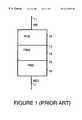
- FIG. 1is a simplified block diagram which shows organization of sublayers within the 100BASE-TX technology physical sublayer (PHY), as defined in Clauses 24 and 25 of the specification IEEE 802.3u-1995.
- PHYphysical sublayer
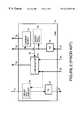
- FIG. 2is a functional block diagram of the Physical Media Access (PMA) sublayer within the PHY, as defined in Clauses 24 and 25 of the specification IEEE 802.3u-1995.
- PMAPhysical Media Access
- FIG. 3is a state machine for a link monitor within the PMA shown in FIG. 2, in accordance with a preferred embodiment of the present invention.
- FIG. 4is a state machine for a link monitor within the PMA shown in FIG. 2, in accordance with an alternative preferred embodiment of the present invention.
- FIG. 1is a simplified block diagram which shows organization of sublayers within the 100BASE-TX technology physical sublayer (PHY), as defined in Clauses 24 and 25 of the specification IEEE 802.3u-1995.
- PHYphysical sublayer
- a Physical Coding Sublayer (PCS) 12defines how data is encoded and decoded, how the Carrier Sense (CS) and Collision Detection (CD) functions work, and the interface between higher and lower layers in the protocol specification.
- a Physical Media Access (PMA) sublayer 14defines the mapping of code bits, generation of a control signal (link_status) which indicates the availability of a Physical Media Dependent (PMD) sublayer 16 , generation of control signals to the PCS that indicate Carrier Sense, Collision Detection and Physical Layer Errors, and clock recovery.
- Physical Media Dependent (PMD) sublayer 16defines the signaling method and parameters for the various physical parameters that are necessary to address the link's physical requirements.
- PCS 12uses a media independent interface (MII) 11 as a service interface to transfer information to and from a media access control (MAC) (via a Reconciliation sublayer) or another PCS client, such as a repeater. Further definition of MII 11 is given in Clause 22 of the specification IEEE 802.3u-1995.
- MIImedia independent interface
- MACmedia access control
- a Media Dependent Interface (MDI) 17provides the actual medium attachment, including connectors, for various supported media.
- the 100BASE-TX technologyas defined in the specification IEEE 802.3u-1995, does not specify MDI 17 other than including he appropriate standard by reference along with the minor adaptations necessary for 100BASE-TX.
- PMA 14communicates with PCS 12 through a PMA service interface 13 .
- PMD 16communicates with PMA 14 through a PMD service interface 15 .
- FIG. 2is a functional block diagram of Physical Media Access (PMA) sublayer 14 , as defined in Clause 24 of the specification IEEE 802.3u-1995 .
- PMAPhysical Media Access
- Transmit logic (TX) 22is used to forward data received from PCS 12 on transmission channel (tx_code-bit) 31 to PMD 16 over transmit (tx_nrzi-bit) channel 27 .
- Receive logic (RX) 26is used to forward data received from PMD 16 on reception channel (rx_nrzi-bit) 30 to PCS 12 over reception channel (rx_code-bit) 33 .
- Carrier detect logic 24based on data placed on reception channel (rx_code-bit) 33 , generates two status signals (carrier_status and rxerror_status) which are placed on lines 34 .
- a link monitor state machine 23generates a link_status signal sent to PCS 12 over a channel 32 .
- Link monitor state machine 23generates the link_status signal based on a signal_status signal on a line 28 .
- Additional signals usedinclude a link_control signal placed on a channel 29 and/or a fault detection signal generated by Far-End fault detect logic 25 , if present.
- Far-End fault detect logic 25permits the station to transmit a special Far-End Fault Indication to its far-end peer.
- the Far-End Fault Indicationis sent only when a physical error condition is sensed on the receive channel. In all other situations, including reception of the Far-End Fault Indication itself, PMA 14 passes through tx_code-bit.
- Far-End Fault Indicationis implemented through Far-End fault detect logic 25 , Far-End fault generate logic 21 and link monitor state machine 23 .
- the transmission of the Far-End Fault Indicationmay start or stop at any time depending only on signal_status.
- Far-End fault detect logic 25process continuously monitors rx_code-bits from RX 26 for the Far-End Fault Indication.
- Detection of the Far-End Fault Indicationdisables the station by asserting a faulting signal 35 and causing link monitor state machine 23 to deassert link_status, which in turn causes the station to source IDLE.
- Far-End fault detect logic 25can also be used for other management functions.
- the LINK MONITOR state machine described in section 24.3.4.4 and by a diagram depicted in FIGS. 24-15 of the specification IEEE 802.3u-1995assumes that if a link has been connected and the signal energy is sufficient to cause an indication of “signal_status ON” for more than 330 micro-seconds, then the link must be reliable. However, a link which exceeds the signal amplitude requirements to generate a “signal_status ON” may in fact have a Bit Error Rate (BER) that is substantially above the acceptable level as defined by requirements set out in the specification IEEE 802.3u-1995. A link which has a Bit Error Rate (BER) that is substantially above the acceptable level is unreliable.
- BERBit Error Rate
- link monitor state machine 23is modified to provide a mechanism for ensuring that the link is indeed reliable.
- Link monitor state machine 23provides a method for evaluating the content of information on the link at a level that is readily available to this sublayer and then provides an algorithm for determining that the BER is acceptable.
- link monitor state machine 23provides a method of bringing the link_status signal down, notifying upper protocol layers of the condition, and returning to a state where the link status may be returned to LINK UP when BER has reached an acceptable level.
- link monitor state machine 23allows the upper layers of the 802.3u protocol to rely upon PCS 12 , PMA 14 and PMD 16 . Instead of getting false “Carrier Sense” or false “Collision Detection”, the protocol will perform reliably.
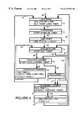
- FIG. 3is a state diagram for link monitor state machine 23 in accordance with a preferred embodiment of the present invention.
- link monitor state machine 23enters a link down state 41 upon reset being equal to TRUE, signal_status being equal to OFF, faulting being equal to TRUE, or link_control being equal to DISABLE.
- link_statusis set equal to FAIL
- idle_timeris set equal to the constant min _timer.
- the constant min_timeris equal to 2 21 BT ⁇ 25%, where BT represents bit times.
- BTis equal to 8 nanoseconds.
- Link down state 41is the state that link monitor state machine 23 enters upon the link going down.
- link monitor state machine 23transitions from link down state 41 to a hysteresis state 42 .
- a stabilization timer(stabilize_timer) is started.
- stabilize_timeris equal to, for example, 330 microseconds to 1 millisecond.
- the stabilization timerallows the lower layer circuit (PMD 16 ) to begin adapting its adaptive equalizer, and PMA 14 to establish its phase lock loop (PLL) and PCS 12 to synchronize its scrambler.
- link monitor state machine 23transitions from hysteresis state 42 to a link ready state 43 .
- link ready state 43link_status is set equal to ready.
- link monitor state machine 23transitions from link ready state 43 to an evaluate link state 44 .
- evaluate link state 44an idle_timer is started.
- link monitor state machine 23transitions from evaluate link state 43 to an evaluate carrier state 45 .
- evaluate carrier state 45a valid_carrier_timer is started.
- link monitor state machine 23transitions from evaluate carrier state 45 to an increment criteria state 46 .
- the idle_timeris adjusted to be equal to a maximum of the current value of idle_timer multiplied by eight, or the constant max_timer.
- the constant max_timeris equal to 2 27 BT ⁇ 25%.
- FCC(X)is set equal to the current value of FCC(X) plus 1.
- FCC(X)is the false carrier count.
- FCCLimitis equal to 2.
- link monitor state machine 23transitions from increment criteria state 46 back to evaluate link state 44 .
- link monitor state machine 23transitions from increment criteria state 46 back to link down state 41 .
- link monitor state machine 23transitions from evaluate carrier state 45 to valid carrier state 47 . Entry into valid carrier state 47 indicates that the packet has proceeded normally. In valid carrier state 47 , FCC(X) is set equal to 0. Link monitor state machine 23 will stay in valid carrier state 47 until other carrier_status event occurs or the idle_timer expires.
- link monitor state machine 23transitions from valid carrier state 47 back to evaluate carrier state 45 .
- link monitor state machine 23transitions from valid carrier state 47 to a decrement criteria state 48 .
- decrement criteria state 48the idle_timer is adjusted to be equal to a minimum of the current value of idle_timer divided eight, or the constant min_timer. Idle_timer is reduced to a minimum to help ensure that a reliable link is not burdened with excessive BER requirements. This makes link initialization expedient.
- link monitor state machine 23transitions from decrement criteria state 48 to a link up state 49 .
- link_statusis set to OK.
- link monitor state machine 23transitions from link up state 49 back to evaluate link state 44 .
- link monitor state machine 23transitions from link up state 49 back to link down state 41 .
- link_controlis equal to SCAN_FOR_CARRIER, this indicates that an auto-negotiation block wants to bring down and re-establish the link.
- link monitor state machine 23transitions from evaluate link state 44 to decrement criteria state 48 .
- link monitor state machine 23In an alternative embodiment of link monitor state machine 23 shown in FIG. 4, FCC(X) is set to zero in a link up state rather than the valid carrier state.
- FCCLimite.g. 2, 2
- link monitor state machine 23enters a link down state 71 upon reset being equal to TRUE, signal_status being equal to OFF, faulting being equal to TRUE, or link_control being equal to DISABLE.
- link_statusis set equal to FAIL
- idle_timeris set equal to the constant min_timer. For example, the constant min_timer is equal to 2 21 BT ⁇ 25%.
- Link down state 71is the state that link monitor state machine 23 enters upon reset or a determination that the link is down.
- link monitor state machine 23transitions from link down state 71 to a hysteresis state 72 .
- a stabilization timer(stabilize_timer) is started.
- stabilize_timeris equal to, for example, 330 microseconds to 1 millisecond.
- the stabilization timerallows the lower layer circuit (PMD 16 ) to begin adapting its adaptive equalizer, and PMA 14 to establish its phase lock loop (PLL) and PCS 12 to synchronize its scrambler.
- link monitor state machine 23transitions from hysteresis state 72 to a link ready state 73 .
- link_statusis set equal to ready.
- link monitor state machine 23transitions from link ready state 73 to an evaluate link state 74 .
- evaluate link state 74an idle_timer is started.
- link monitor state machine 23transitions from evaluate link state 73 to an evaluate carrier state 75 .
- evaluate carrier state 75a valid_carrier_timer is started.
- link monitor state machine 23transitions from evaluate carrier state 75 to an increment criteria state 76 .
- increment criteria state 76the idle_timer is adjusted to be equal to a maximum of the current value of idle_timer multiplied by eight, or the constant max_timer.
- the constant max_timeris equal to 2 27 BT ⁇ 25%.
- FCC(X)is set equal to the current value of FCC(X) plus 1.
- FCC(X)is the false carrier count.
- FCCLimitis equal to 2.
- link monitor state machine 23transitions from increment criteria state 76 back to evaluate link state 74 .
- link monitor state machine 23transitions from increment criteria state 76 back to link down state 71 .
- link monitor state machine 23transitions from evaluate carrier state 75 to valid carrier state 77 . Entry into valid carrier state 77 indicates that the packet has proceeded normally. Link monitor state machine 23 will stay in valid carrier state 77 until other carrier_status event occurs or the idle_timer expires.
- link monitor state machine 23transitions from valid carrier state 77 back to evaluate carrier state 75 .
- link monitor state machine 23transitions from valid carrier state 77 to a decrement criteria state 78 .
- decrement criteria state 78the idle_timer is adjusted to be equal to a minimum of the current value of idle_timer divided by eight, or the constant min_timer. Idle_timer is reduced to a minimum to help ensure that a reliable link is not burdened with excessive BER requirements and speed up link initialization.
- link monitor state machine 23transitions from decrement criteria state 78 to a link up state 79 .
- link_statusis set to OK.
- FCC(X)is set equal to 0.
- link monitor state machine 23transitions from link up state 79 back to evaluate link state 74 .
- link monitor state machine 23transitions from link up state 79 back to link down state 71 .
- link_controlis equal to SCAN_FOR_CARRIER, this indicates that auto-negotiation wants to bring the link down and re-establish the link.
- link monitor state machine 23transitions from evaluate link state 74 to decrement criteria state 78 .
Landscapes
- Engineering & Computer Science (AREA)
- Computer Networks & Wireless Communication (AREA)
- Signal Processing (AREA)
- Environmental & Geological Engineering (AREA)
- Small-Scale Networks (AREA)
Abstract
Description
Claims (21)
Priority Applications (1)
| Application Number | Priority Date | Filing Date | Title |
|---|---|---|---|
| US09/044,640US6222854B1 (en) | 1998-03-19 | 1998-03-19 | Link monitor state machine |
Applications Claiming Priority (1)
| Application Number | Priority Date | Filing Date | Title |
|---|---|---|---|
| US09/044,640US6222854B1 (en) | 1998-03-19 | 1998-03-19 | Link monitor state machine |
Publications (1)
| Publication Number | Publication Date |
|---|---|
| US6222854B1true US6222854B1 (en) | 2001-04-24 |
Family
ID=21933488
Family Applications (1)
| Application Number | Title | Priority Date | Filing Date |
|---|---|---|---|
| US09/044,640Expired - LifetimeUS6222854B1 (en) | 1998-03-19 | 1998-03-19 | Link monitor state machine |
Country Status (1)
| Country | Link |
|---|---|
| US (1) | US6222854B1 (en) |
Cited By (20)
| Publication number | Priority date | Publication date | Assignee | Title |
|---|---|---|---|---|
| US20020118412A1 (en)* | 2001-02-23 | 2002-08-29 | Patrick Gibson | Network device including detection of link status employing auto-negotiation |
| WO2002098059A1 (en)* | 2001-05-28 | 2002-12-05 | Nokia Corporation | Method and system for implementing a fast recovery process in a local area network |
| US20030009555A1 (en)* | 1999-08-30 | 2003-01-09 | Corporate Performance Resources, L.L.C. | Measuring a page-specific subjective user reaction concerning each of multiple web pages of a website |
| WO2003090083A1 (en)* | 2002-04-16 | 2003-10-30 | Meshnetworks, Inc. | System and method for selecting reliable links between nodes in an ad-hoc communication network |
| US20040039850A1 (en)* | 2002-08-20 | 2004-02-26 | Realtek Semiconductor Corp. | Apparatus and method for automatically configuring network media connection |
| US6707794B1 (en)* | 1999-11-15 | 2004-03-16 | Networks Associates Technology, Inc. | Method, system and computer program product for physical link layer handshake protocol analysis |
| US20050076129A1 (en)* | 2003-09-24 | 2005-04-07 | Adc Telecommunications, Inc. | 10/100 Mbs network device |
| US20050249123A1 (en)* | 2004-05-10 | 2005-11-10 | Finn Norman W | System and method for detecting link failures |
| US20060126498A1 (en)* | 2004-11-22 | 2006-06-15 | Alexander Gross | Method for operating a network having a ring topology |
| CN1332533C (en)* | 2004-03-18 | 2007-08-15 | 华为技术有限公司 | A method for monitoring adjacent access networks and links between them |
| US20100211831A1 (en)* | 2009-02-19 | 2010-08-19 | Fujitsu Limited | Fault notification method and communication apparatus |
| US20110173354A1 (en)* | 2010-01-08 | 2011-07-14 | Hall Kenwood H | Hardware Based Connection State Machine With Built In Timers |
| WO2013033101A1 (en)* | 2011-08-30 | 2013-03-07 | Adc Dsl Systems, Inc. | Rate adaptive auto-negotiation |
| US8599679B1 (en)* | 2007-05-16 | 2013-12-03 | Marvell International Ltd. | Fast link down |
| US20140228040A1 (en)* | 2010-08-31 | 2014-08-14 | At&T Intellectual Property I, L.P. | Tail optimization protocol for cellular radio resource allocation |
| US9578441B2 (en) | 2010-12-14 | 2017-02-21 | At&T Intellectual Property I, L.P. | Intelligent mobility application profiling tool |
| US9654950B2 (en) | 2011-06-20 | 2017-05-16 | At&T Intellectual Property I, L.P. | Controlling traffic transmissions to manage cellular radio resource utilization |
| US9699737B2 (en) | 2011-06-20 | 2017-07-04 | At&T Intellectual Property I, L.P. | Bundling data transfers and employing tail optimization protocol to manage cellular radio resource utilization |
| US10955471B2 (en)* | 2007-06-07 | 2021-03-23 | Texas Instruments Incorporated | Operating state machine controllers after powering, decoupling, monitoring, coupling communications |
| CN114020677A (en)* | 2021-11-08 | 2022-02-08 | 无锡众星微系统技术有限公司 | STP connection management method and device |
Citations (4)
| Publication number | Priority date | Publication date | Assignee | Title |
|---|---|---|---|---|
| US5577069A (en)* | 1994-08-02 | 1996-11-19 | National Semiconductor Corporation | Signalling method and structure suitable for out-of-band information transfer in communication network |
| US5754540A (en)* | 1995-07-18 | 1998-05-19 | Macronix International Co., Ltd. | Expandable integrated circuit multiport repeater controller with multiple media independent interfaces and mixed media connections |
| US5754552A (en)* | 1995-07-12 | 1998-05-19 | Compaq Computer Corporation | Automatic communication protocol detection system and method for network systems |
| US6141352A (en)* | 1997-10-10 | 2000-10-31 | Nortel Networks Limited | Method and apparatus for transmitting 10BASE-T signals across a 100BASE-X physical layer device service interface |
- 1998
- 1998-03-19USUS09/044,640patent/US6222854B1/ennot_activeExpired - Lifetime
Patent Citations (4)
| Publication number | Priority date | Publication date | Assignee | Title |
|---|---|---|---|---|
| US5577069A (en)* | 1994-08-02 | 1996-11-19 | National Semiconductor Corporation | Signalling method and structure suitable for out-of-band information transfer in communication network |
| US5754552A (en)* | 1995-07-12 | 1998-05-19 | Compaq Computer Corporation | Automatic communication protocol detection system and method for network systems |
| US5754540A (en)* | 1995-07-18 | 1998-05-19 | Macronix International Co., Ltd. | Expandable integrated circuit multiport repeater controller with multiple media independent interfaces and mixed media connections |
| US6141352A (en)* | 1997-10-10 | 2000-10-31 | Nortel Networks Limited | Method and apparatus for transmitting 10BASE-T signals across a 100BASE-X physical layer device service interface |
Non-Patent Citations (1)
| Title |
|---|
| IEEE Std 802.3u (CSMA/CD) Chapter 24 and 25, (1995), pp. 157-197. |
Cited By (41)
| Publication number | Priority date | Publication date | Assignee | Title |
|---|---|---|---|---|
| US20030009555A1 (en)* | 1999-08-30 | 2003-01-09 | Corporate Performance Resources, L.L.C. | Measuring a page-specific subjective user reaction concerning each of multiple web pages of a website |
| US6707794B1 (en)* | 1999-11-15 | 2004-03-16 | Networks Associates Technology, Inc. | Method, system and computer program product for physical link layer handshake protocol analysis |
| US20020118412A1 (en)* | 2001-02-23 | 2002-08-29 | Patrick Gibson | Network device including detection of link status employing auto-negotiation |
| US7023873B2 (en)* | 2001-02-23 | 2006-04-04 | 3Com Corporation | Network device including detection of link status employing auto-negotiation |
| US20040105390A1 (en)* | 2001-05-28 | 2004-06-03 | Nokia Corporation | Method and system for implementing a fast recovery process in a local area network |
| WO2002098059A1 (en)* | 2001-05-28 | 2002-12-05 | Nokia Corporation | Method and system for implementing a fast recovery process in a local area network |
| WO2003090083A1 (en)* | 2002-04-16 | 2003-10-30 | Meshnetworks, Inc. | System and method for selecting reliable links between nodes in an ad-hoc communication network |
| US7107498B1 (en)* | 2002-04-16 | 2006-09-12 | Methnetworks, Inc. | System and method for identifying and maintaining reliable infrastructure links using bit error rate data in an ad-hoc communication network |
| US20040039850A1 (en)* | 2002-08-20 | 2004-02-26 | Realtek Semiconductor Corp. | Apparatus and method for automatically configuring network media connection |
| US20050076129A1 (en)* | 2003-09-24 | 2005-04-07 | Adc Telecommunications, Inc. | 10/100 Mbs network device |
| US7676592B2 (en) | 2003-09-24 | 2010-03-09 | Adc Telecommunications, Inc. | 10/100 Mbs network device |
| CN1332533C (en)* | 2004-03-18 | 2007-08-15 | 华为技术有限公司 | A method for monitoring adjacent access networks and links between them |
| US7983173B2 (en)* | 2004-05-10 | 2011-07-19 | Cisco Technology, Inc. | System and method for detecting link failures |
| US20050249123A1 (en)* | 2004-05-10 | 2005-11-10 | Finn Norman W | System and method for detecting link failures |
| US8576699B2 (en)* | 2004-11-22 | 2013-11-05 | Robert Bosch Gmbh | Method for operating a network having a ring topology |
| US20060126498A1 (en)* | 2004-11-22 | 2006-06-15 | Alexander Gross | Method for operating a network having a ring topology |
| US9154271B1 (en)* | 2007-05-16 | 2015-10-06 | Marvell International Ltd. | Method and apparatus for a physical layer device (PHY) to determine a status of a link in a network |
| US8599679B1 (en)* | 2007-05-16 | 2013-12-03 | Marvell International Ltd. | Fast link down |
| US11867759B2 (en) | 2007-06-07 | 2024-01-09 | Texas Instruments Incorporated | Synchronizing a device that has been power cycled to an already operational system |
| US11567129B2 (en)* | 2007-06-07 | 2023-01-31 | Texas Instruments Incorporated | Synchronizing a device that has been power cycled to an already operational system |
| US10955471B2 (en)* | 2007-06-07 | 2021-03-23 | Texas Instruments Incorporated | Operating state machine controllers after powering, decoupling, monitoring, coupling communications |
| US20210231733A1 (en)* | 2007-06-07 | 2021-07-29 | Texas Instruments Incorporated | Synchronizing a device that has been power cycled to an already operational system |
| US8289855B2 (en)* | 2009-02-19 | 2012-10-16 | Fujitsu Limited | Fault notification method and communication apparatus |
| US20100211831A1 (en)* | 2009-02-19 | 2010-08-19 | Fujitsu Limited | Fault notification method and communication apparatus |
| US20110173354A1 (en)* | 2010-01-08 | 2011-07-14 | Hall Kenwood H | Hardware Based Connection State Machine With Built In Timers |
| EP2343650A3 (en)* | 2010-01-08 | 2011-09-07 | Rockwell Automation Technologies, Inc. | Hardware based connection state machine with built in timers |
| US20140228040A1 (en)* | 2010-08-31 | 2014-08-14 | At&T Intellectual Property I, L.P. | Tail optimization protocol for cellular radio resource allocation |
| US20160286415A1 (en)* | 2010-08-31 | 2016-09-29 | At&T Intellectual Property I, L.P. | Tail optimization protocol for cellular radio resource allocation |
| US9374824B2 (en)* | 2010-08-31 | 2016-06-21 | At&T Intellectual Property I, L.P. | Tail optimization protocol for cellular radio resource allocation |
| US10244410B2 (en)* | 2010-08-31 | 2019-03-26 | At&T Intellectual Property I, L.P. | Tail optimization protocol for cellular radio resource allocation |
| US9578441B2 (en) | 2010-12-14 | 2017-02-21 | At&T Intellectual Property I, L.P. | Intelligent mobility application profiling tool |
| US10165576B2 (en) | 2011-06-20 | 2018-12-25 | At&T Intellectual Property I, L.P. | Controlling traffic transmissions to manage cellular radio resource utilization |
| US10064195B2 (en) | 2011-06-20 | 2018-08-28 | At&T Intellectual Property I, L.P. | Controlling traffic transmissions to manage cellular radio resource utilization |
| US10306665B2 (en) | 2011-06-20 | 2019-05-28 | At&T Intellectual Property I, L.P. | Bundling data transfers and employing tail optimization protocol to manage cellular radio resource utilization |
| US10638499B2 (en) | 2011-06-20 | 2020-04-28 | At&T Intellectual Property I, L.P. | Bundling data transfers and employing tail optimization protocol to manage cellular radio resource utilization |
| US9699737B2 (en) | 2011-06-20 | 2017-07-04 | At&T Intellectual Property I, L.P. | Bundling data transfers and employing tail optimization protocol to manage cellular radio resource utilization |
| US9654950B2 (en) | 2011-06-20 | 2017-05-16 | At&T Intellectual Property I, L.P. | Controlling traffic transmissions to manage cellular radio resource utilization |
| US8732262B2 (en) | 2011-08-30 | 2014-05-20 | Adc Dsl Systems, Inc. | Rate adaptive auto-negotiation |
| WO2013033101A1 (en)* | 2011-08-30 | 2013-03-07 | Adc Dsl Systems, Inc. | Rate adaptive auto-negotiation |
| CN114020677A (en)* | 2021-11-08 | 2022-02-08 | 无锡众星微系统技术有限公司 | STP connection management method and device |
| CN114020677B (en)* | 2021-11-08 | 2022-10-11 | 无锡众星微系统技术有限公司 | STP connection management method and device |
Similar Documents
| Publication | Publication Date | Title |
|---|---|---|
| US6222854B1 (en) | Link monitor state machine | |
| EP0573204B1 (en) | Network connection method | |
| US5825755A (en) | Method and apparatus for switching between full-duplex and half-duplex CSMA/CD systems | |
| EP1168717B1 (en) | Method and apparatus for regulating transceiver power consumption in a communications network | |
| JP3872847B2 (en) | Full-duplex flow control for Ethernet | |
| US5905870A (en) | Arrangement for initiating and maintaining flow control in shared-medium, full-duplex, and switched networks | |
| EP0925666B1 (en) | Method and system for identifying an error condition due to a faulty cable connection in an ethernet network | |
| US6690650B1 (en) | Arrangement in a network repeater for monitoring link integrity by monitoring symbol errors across multiple detection intervals | |
| US6603741B1 (en) | Monitoring of connection between network devices in a packet-based communication system | |
| US6600755B1 (en) | Link technology detection in multiple speed physical links | |
| US6141350A (en) | Auto-negotiation using negative link pulses | |
| WO2009123988A1 (en) | Ethernet physical layer transceiver with auto-ranging function | |
| US7564904B2 (en) | Apparatus for and method of detection of powered devices over a network | |
| EP1275217B1 (en) | Performance indicator for a high-speed communication system | |
| US20040199834A1 (en) | Transceiver circuit, transceiving method, and transceiver apparatus | |
| US20040001440A1 (en) | Powerline network bridging congestion control | |
| US8184677B1 (en) | Arrangement in a network repeater for monitoring link integrity and automatically down shifting link speed | |
| JPH11355383A (en) | Detection of small power signal for automatic negotiation | |
| US20060039399A1 (en) | Communication device and communication mode setting method | |
| US7116678B2 (en) | High speed physical layer for CSMA/CD systems | |
| US20080013565A1 (en) | Reverse Polling Algorithm For Shared Resources To Reduce Collisions In A Network | |
| US6026096A (en) | Automatic speed sensing in a token ring local area network | |
| JP2001292150A (en) | Communication control method | |
| US20030058841A1 (en) | Anti-offline device adapted to be used in home PNA compliant network system and the data packet transmission method thereof | |
| WO2001006706A2 (en) | A method and apparatus for verifying connectivity among nodes in a communications network |
Legal Events
| Date | Code | Title | Description |
|---|---|---|---|
| AS | Assignment | Owner name:HEWLETT-PACKARD COMPANY, CALIFORNIA Free format text:ASSIGNMENT OF ASSIGNORS INTEREST;ASSIGNOR:DOVE, DANIEL JOSEPH;REEL/FRAME:009111/0493 Effective date:19980317 | |
| AS | Assignment | Owner name:HEWLETT-PACKARD COMPANY, COLORADO Free format text:MERGER;ASSIGNOR:HEWLETT-PACKARD COMPANY;REEL/FRAME:011523/0469 Effective date:19980520 | |
| STCF | Information on status: patent grant | Free format text:PATENTED CASE | |
| FPAY | Fee payment | Year of fee payment:4 | |
| FPAY | Fee payment | Year of fee payment:8 | |
| AS | Assignment | Owner name:HEWLETT-PACKARD DEVELOPMENT COMPANY, L.P., TEXAS Free format text:ASSIGNMENT OF ASSIGNORS INTEREST;ASSIGNOR:HEWLETT-PACKARD COMPANY;REEL/FRAME:026945/0699 Effective date:20030131 | |
| FPAY | Fee payment | Year of fee payment:12 | |
| AS | Assignment | Owner name:HEWLETT PACKARD ENTERPRISE DEVELOPMENT LP, TEXAS Free format text:ASSIGNMENT OF ASSIGNORS INTEREST;ASSIGNOR:HEWLETT-PACKARD DEVELOPMENT COMPANY, L.P.;REEL/FRAME:037079/0001 Effective date:20151027 |