US6222853B1 - Communication system for a line network - Google Patents
Communication system for a line networkDownload PDFInfo
- Publication number
- US6222853B1 US6222853B1US08/941,115US94111597AUS6222853B1US 6222853 B1US6222853 B1US 6222853B1US 94111597 AUS94111597 AUS 94111597AUS 6222853 B1US6222853 B1US 6222853B1
- Authority
- US
- United States
- Prior art keywords
- device identifier
- transmission line
- control system
- transmission
- socket
- Prior art date
- Legal status (The legal status is an assumption and is not a legal conclusion. Google has not performed a legal analysis and makes no representation as to the accuracy of the status listed.)
- Expired - Lifetime
Links
Images

Classifications
- H—ELECTRICITY
- H02—GENERATION; CONVERSION OR DISTRIBUTION OF ELECTRIC POWER
- H02J—CIRCUIT ARRANGEMENTS OR SYSTEMS FOR SUPPLYING OR DISTRIBUTING ELECTRIC POWER; SYSTEMS FOR STORING ELECTRIC ENERGY
- H02J13/00—Circuit arrangements for providing remote indication of network conditions, e.g. an instantaneous record of the open or closed condition of each circuitbreaker in the network; Circuit arrangements for providing remote control of switching means in a power distribution network, e.g. switching in and out of current consumers by using a pulse code signal carried by the network
- H02J13/00006—Circuit arrangements for providing remote indication of network conditions, e.g. an instantaneous record of the open or closed condition of each circuitbreaker in the network; Circuit arrangements for providing remote control of switching means in a power distribution network, e.g. switching in and out of current consumers by using a pulse code signal carried by the network characterised by information or instructions transport means between the monitoring, controlling or managing units and monitored, controlled or operated power network element or electrical equipment
- H02J13/00016—Circuit arrangements for providing remote indication of network conditions, e.g. an instantaneous record of the open or closed condition of each circuitbreaker in the network; Circuit arrangements for providing remote control of switching means in a power distribution network, e.g. switching in and out of current consumers by using a pulse code signal carried by the network characterised by information or instructions transport means between the monitoring, controlling or managing units and monitored, controlled or operated power network element or electrical equipment using a wired telecommunication network or a data transmission bus
- H02J13/00017—Circuit arrangements for providing remote indication of network conditions, e.g. an instantaneous record of the open or closed condition of each circuitbreaker in the network; Circuit arrangements for providing remote control of switching means in a power distribution network, e.g. switching in and out of current consumers by using a pulse code signal carried by the network characterised by information or instructions transport means between the monitoring, controlling or managing units and monitored, controlled or operated power network element or electrical equipment using a wired telecommunication network or a data transmission bus using optical fiber
- H—ELECTRICITY
- H02—GENERATION; CONVERSION OR DISTRIBUTION OF ELECTRIC POWER
- H02J—CIRCUIT ARRANGEMENTS OR SYSTEMS FOR SUPPLYING OR DISTRIBUTING ELECTRIC POWER; SYSTEMS FOR STORING ELECTRIC ENERGY
- H02J13/00—Circuit arrangements for providing remote indication of network conditions, e.g. an instantaneous record of the open or closed condition of each circuitbreaker in the network; Circuit arrangements for providing remote control of switching means in a power distribution network, e.g. switching in and out of current consumers by using a pulse code signal carried by the network
- H02J13/00032—Systems characterised by the controlled or operated power network elements or equipment, the power network elements or equipment not otherwise provided for
- H02J13/0005—Systems characterised by the controlled or operated power network elements or equipment, the power network elements or equipment not otherwise provided for the elements or equipment being or involving power plugs or sockets
- Y—GENERAL TAGGING OF NEW TECHNOLOGICAL DEVELOPMENTS; GENERAL TAGGING OF CROSS-SECTIONAL TECHNOLOGIES SPANNING OVER SEVERAL SECTIONS OF THE IPC; TECHNICAL SUBJECTS COVERED BY FORMER USPC CROSS-REFERENCE ART COLLECTIONS [XRACs] AND DIGESTS
- Y02—TECHNOLOGIES OR APPLICATIONS FOR MITIGATION OR ADAPTATION AGAINST CLIMATE CHANGE
- Y02B—CLIMATE CHANGE MITIGATION TECHNOLOGIES RELATED TO BUILDINGS, e.g. HOUSING, HOUSE APPLIANCES OR RELATED END-USER APPLICATIONS
- Y02B90/00—Enabling technologies or technologies with a potential or indirect contribution to GHG emissions mitigation
- Y02B90/20—Smart grids as enabling technology in buildings sector
- Y—GENERAL TAGGING OF NEW TECHNOLOGICAL DEVELOPMENTS; GENERAL TAGGING OF CROSS-SECTIONAL TECHNOLOGIES SPANNING OVER SEVERAL SECTIONS OF THE IPC; TECHNICAL SUBJECTS COVERED BY FORMER USPC CROSS-REFERENCE ART COLLECTIONS [XRACs] AND DIGESTS
- Y04—INFORMATION OR COMMUNICATION TECHNOLOGIES HAVING AN IMPACT ON OTHER TECHNOLOGY AREAS
- Y04S—SYSTEMS INTEGRATING TECHNOLOGIES RELATED TO POWER NETWORK OPERATION, COMMUNICATION OR INFORMATION TECHNOLOGIES FOR IMPROVING THE ELECTRICAL POWER GENERATION, TRANSMISSION, DISTRIBUTION, MANAGEMENT OR USAGE, i.e. SMART GRIDS
- Y04S40/00—Systems for electrical power generation, transmission, distribution or end-user application management characterised by the use of communication or information technologies, or communication or information technology specific aspects supporting them
- Y04S40/12—Systems for electrical power generation, transmission, distribution or end-user application management characterised by the use of communication or information technologies, or communication or information technology specific aspects supporting them characterised by data transport means between the monitoring, controlling or managing units and monitored, controlled or operated electrical equipment
- Y04S40/124—Systems for electrical power generation, transmission, distribution or end-user application management characterised by the use of communication or information technologies, or communication or information technology specific aspects supporting them characterised by data transport means between the monitoring, controlling or managing units and monitored, controlled or operated electrical equipment using wired telecommunication networks or data transmission busses
Definitions
- the present inventionrelates generally to the field of electronic controls and, more particularly, the present invention relates to a method for operating a communication system and/or control system via a line network equipped with socket outlets in which at least one transmission line is arranged in at least one socket outlet for supplying standardized supply voltage.
- a method for operating a control system of this typeis set forth in PCT application WO 89/12950, which employs a thyristor control.
- ignition impulses for the thyristorare transmitted via the transmission line.
- the thyristoris an essential part of a brightness control for lighting a room.
- the principle of operationemploys the phase intersection control of the thyristor, in which driving takes place differently depending on the timing of a respective ignition impulse of the thyristor.
- An analog phase signalthus finally controls the thyristor, so that the transmission protocol comprises only a transmission of the ignition impulses.
- the preset phase position of the ignition impulsescauses a desired brightness of the lighting.
- One aim of the present inventionis to provide a simple method for operating a communication system and/or control system that reduces operating expense, materials expense, installation expense and maintenance expense in the field of building services management.
- transmissiontakes place according to one of at least two selectable transmission protocols, whereby one of the two transmission protocols is selected according to the type of apparatus which is plugged in.
- the present inventionis based on the recognition that the socket outlets already present in each building can be used to operate a communication system and/or control system.
- the supply voltage network standardized in each country, including standardized plug sockets,is particularly well suited for the construction of a communication system and/or control system, because the devices that belong to the communication and/or control system require a standard supply voltage.
- the supply voltage linesare the lines which account for the largest use of material. If the existing supply voltage network is also included in the construction of the communication system and/or supply system, then the complete construction of additional separate networks can be avoided.
- the transmissionis carried out according to one of at least two selectable transmission protocols.
- These transmission protocolscan be, for example, protocols for transmission of digital speech signals during telephoning, protocols for transmitting digital radio data, protocols for transmitting digital image data, simple analog or digital control protocols, simple analog sensor protocols and/or protocols for transmitting digital data between different data processing apparatuses.
- the standard supply voltage networkis the only line network in a building. It is combined only with the transmission line for the transmission of the apparatus-specific signals. Within the individual transmission protocols, different transmission speeds can be defined for the respective transmission protocol.
- the transmission protocolis selected according to the type of apparatus being used. This means that an allocation ensues between devices that can be operated in the communication system and/or control system and selectable transmission protocols, as well as, if warranted, an allocation of transmission speeds. A determined transmission protocol is allocated to each type of connected apparatus.
- the transmission lineis an optical cable, such as, for example, a glass fiber cable.
- the transmission of the apparatus-specific signals on the optical cablehas the result that disturbances due to the supply line conducted immediately adjacently are excluded.
- the spacings prescribed according to country-specific standardized regulations between supply voltage lines and galvanic signal linesdo not have to be maintained during an optical transmission.
- a device identifieris generated at the device, which uniquely identifies at least the type of device.
- the device identifieris transmitted via the data line, and the type of device connected is subsequently determined on the basis of the device identifier.
- This exemplary embodimentis based on the consideration that the socket outlets of the standardized supply voltage network are likewise standardized. It is thus unavoidable that devices of the most widely varying types can be plugged into one and the same socket outlet, using plugs of identical construction.
- this measureconsists in the production of a device identifier or by the device or by the plug connected with the device. After the connection of the plug connected with the device into the socket outlet, the device identifier is transmitted via the data line. In a control unit, the type of device connected can be determined on the basis of the device identifier. An allocation of a transmission protocol to a socket outlet, and thus to a connected device, is thus possible without expensive manual programming processes. If the device identifier is also manually produced, the manual expense is thus limited merely to the connection of the device using the plug.
- the method according to the exemplary embodiment of the inventionalso has the result that the control unit is relieved of stress, since the device-specific signals do not have to be addressed for or, respectively, by particular device.
- the control unitAfter the control unit has determined, on the basis of the device identifier, which type of device is connected with the respective data line, only signals required for this device are transmitted on the data line, i.e. sent to the device and/or received by the device.
- the control unitcan determine when the plug of the device is removed from the socket outlet, since in this case the device identifier can no longer be received.
- the control unitactually to transmit the device-specific data only via a transmission line to which a device is connected.
- the control unitalso expects only signals on a transmission line that is actually connected with a device. In this way, the means contained in the control unit can be used effectively; e.g., no time is wasted on superfluous transmission of signals or superfluous waiting for signals.
- the transmission of the device identifiercan take place upon request by the control unit, or else it can be repeated after a predetermined time.
- the expense at the deviceis lower; however, for this an extra expenditure must be operated in the control unit for the transmission of the request.
- a timeris provided at the device; however, the control unit is relieved of stress.
- the device identifieris usefully sent only when no signals are currently being transmitted on the transmission line. By means of this measure, interruptions of the signal transmission are prevented by the transmission of the device identifier. The transmission of the device thereby has no influence on the transmission speed of the signals. Moreover, in the case of the transmission of signals to the control unit by the device, the control unit can already determine on the basis of an interrupted signal transmission that the device is no longer connected with the data line.
- the connected deviceis identified on the basis of a transmitted identification symbol contained in the device identifier, which identification symbol unambiguously identifies the device in the manner of an identification code.
- the identification codecan, for example, contain a name or a number.
- control unitin the control unit or, respectively, in the receiver of the device identifiers, not only are items of information provided concerning the type of a connected device, but different devices within a type of device can also be distinguished on the basis of the identification. If the identifications are, for example, allocated to various users, then the control unit can allow or forbid communication processes and/or control processes, depending on the respective user.
- the communication system and/or control systemcontains an input unit with at least two threshold units.
- the input unitis realized in such a way that on the basis of the threshold values it is recognized on which data line a device was connected.
- For the evaluation of the signals of the threshold unitonly the relevant data line is connected with the control unit, using a multiplexer addressing unit. A processing logic for the threshold values is thus required only once for the threshold values. There thus results an input unit that is of simple construction.
- the device identifieris usefully divided into several parts.
- the type of connected devicecan be stored in a type part, items of information concerning the state of the connected device can be encrypted in a maintenance part, and, in a part for error determination, e.g. check sums can be stored, on the basis of which the correct transmission of the device identifier on the transmission line can be checked.
- a status bit in the device identifierit can be indicated whether the device identifier also contains an identification part that unambiguously identifies the connected device in the manner of a name.
- the length of the device identifiercan be matched to the respectively connected device. Given a shorter device identifier, the expense for producing the device identifier and the expense for evaluating the device identifier is thereby reduced.
- Another aspect of the inventionconcerns a device adapter for the communication system and/or control system.
- an intervention in the apparatuscan be omitted, since the device identifier is produced in the adapter.
- the device identifieris automatically produced at least once when the plug of the adapter is connected into the socket outlet, so that, apart from the connecting of the plug, no manual activity is required.
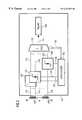
- FIG. 1illustrates a communication and control system for a line network having socket outlets of the present invention
- FIG. 2is a schematic diagram of the input unit of a room control unit
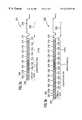
- FIG. 3illustrates the components of a device identifier.
- FIG. 1illustrates a communication and control system 10 for a line network (not shown) equipped with socket outlets 12 to 16 for supplying a standardized supply voltage, e.g. 220V.
- the socket outlets 12 to 16are located in the walls of a room 20 in a building, and are connected with a room control unit 28 via glass fiber cables 22 , 24 or, respectively, 26 .
- the room control unit 28is connected with other room control units (not shown) for other rooms via two lines 30 and 32 .
- the room control units of a floorare preferably connected with one another in annular fashion. In each ring, there is a central control unit for the respective floor. Via the connection of central control units of several floors, there arises a communication and control system for the entire building in which the existing supply voltage network is used.
- the glass fiber cables 22 to 26are connected with the room control unit 28 via an input unit 34 .
- the glass fiber cable 22is connected with the input unit 34 via a photodiode 42 .
- the glass fiber cable 24 or, respectively, 26is connected with the input unit 34 via a photodiode 44 or, respectively, 46 .
- the photodiodes 42 to 46can send out optical signals from the room control unit 28 , and, in a second type of operation, can receive optical signals from the glass fiber cables 22 , 24 or, respectively, 26 .
- the room control unit 28additionally contains a microprocessor 36 and a memory 38 , which are both connected with a bus system 40 consisting of data lines and control lines.
- the bus system 40is also connected with the input unit 34 .
- the microprocessor 36evaluates, for example, the output signals from the input unit 34 , and initiates predetermined control processes according to a predetermined control program.
- the microprocessoradditionally transmits data between the line 30 and the glass fiber cables 22 , 24 or, respectively, 26 , as well as in the inverse direction from the glass fiber cables 22 , 24 or, respectively, 26 to the line 32 .
- an adapter 52is plugged into the socket outlet 12 , which enables the connection of a data processing means 54 to the communication and control system 10 .
- the adapter 52is plugged into the socket outlet 12 via a plug 56 .
- a socket outlet 58into which a network plug (not shown) of the data processing means 54 is plugged.
- a western socket 60for the connection of a modem, with which digital data is transmitted from and/or to the data processing means 54 .
- a control console 62 with a plug 64is plugged into the socket outlet 14 .
- the control console 62contains selection buttons 66 to 80 .
- the selection button 66is allocated to a first lamp 82 , which is connected to a socket outlet of the room 20 . If the button 66 is actuated, the brightness for the lamp 82 can be determined via a rotary switch 84 . In the same way, the brightness for a further lamp 85 in the room 20 can be determined using the selection button 68 .
- the selection button 70permits the predetermination of a temperature value via the rotary switch 84 for a heating unit 86 that heats the room 20 .
- the other selection buttons 72 to 80can be assigned further functions.
- An adapter 87 with a plug 88can be plugged into the socket outlet 16 .
- the adapter 86has a western socket 90 for the connection of a telephone 92 .
- Device identifiers ID 1 to ID 3are produced by the adapters 52 , 87 and the control console 62 .
- the device identifier ID 1is produced by the adapter 52
- the device identifier ID 2is produced by the control console 62
- the device identifier ID 3is produced by the adapter 87 .
- the device identifiers ID 1 , ID 2 or, respectively, ID 3are transmitted via the glass fiber cable 22 , 24 or, respectively, 26 , according to a clock signal produced in the adapter 52 , in the control console 62 , or, respectively, in the adapter 87 .
- the device identifiers ID 1 to ID 3are of identical construction. Their construction is further explained below with reference to FIG. 3 .
- the control unit 28By means of the device identifiers ID 1 , ID 2 and ID 3 , it is possible for the control unit 28 to select, for the connected devices (i.e., for the data processing device 54 , the control console 62 and the telephone apparatus 92 ), allocated transmission protocols and transmission speeds according to which signals are transmitted on the glass fiber cables 22 to 26 to the respective device from the control unit 28 , or, respectively, from the respective apparatus to the control unit 28 .
- the repeated transmission of the device identifiers ID 1 to ID 3 via the glass fiber cables 22 to 26it is possible in the control unit 28 to register the removal of the adapter 52 , of the control console 62 or of the adapter 87 .
- FIG. 2shows a schematic diagram of the input unit 34 , which contains 32 threshold units, of which the threshold units 102 , 104 and 106 are shown in FIG. 2 .
- the threshold unit 102is connected at the input side with the photodiode 42 via a line 112 .
- the threshold unit 104 or, respectively, 106is connected at the input side with the photodiode 44 or, respectively, 46 , via a line 114 or, respectively, 116 .
- the input of the threshold unit 102 or, respectively, the line 112is connected with the first input of a multiplexer 120 via a line 122 .
- the input of the threshold unit 104 or, respectively, 106is connected with a second input or, respectively, with a third input of the multiplexer via a data line 124 or, respectively, 126 .
- the threshold units 102 to 106detect voltage fluctuations on the line 112 , 114 or, respectively, 116 . These voltage fluctuations result from a changed diode current of the photodiodes 42 , 44 or, respectively, 46 upon reception of optical signals via the glass fiber cables 22 , 24 or, respectively, 26 . If a threshold is exceeded in the threshold unit 102 , a voltage value of about 5V is produced on a signal line 132 at the output of the threshold unit 102 . If on the other hand a threshold is exceeded in the threshold unit 104 or, respectively, 106 , a voltage value of 5V is produced on a signal line 134 or, respectively, 136 .
- the signal lines 132 to 136are connected with inputs of a coding unit 140 , which allocates to each of its inputs an address code that is output at the output of the coding unit 140 .
- Address lines 142are connected with the output of the coding unit 140 , which transmit the address code from the coding unit 140 to selection inputs of the multiplexer 120 .
- the multiplexer 120depending on the address code on the address lines 142 , one of the lines 122 , 124 , 126 is connected with the output of the multiplexer.
- a line 144is connected at the output of the multiplexer, which line is connected with a register 146 .
- the register 146contains an additional logic for the removal of preambles (cf. FIG. 3, 208 , 208 ′) for synchronization in the device identifiers ID 1 to ID 3 .
- the additional logicappends a number for the respective socket outlet 12 to 16 , via which the respective device identifier ID 1 to ID 3 was transmitted, to the device identifier ID 1 to ID 3 in the register 146 .
- the register 146is divided into subregisters, in which the components of the device identifiers ID 1 to ID 3 , explained on the basis of FIG. 3, are contained. If the grouping in register 146 is closed, the input unit 34 sends an interrupt signal to the microprocessor 36 , which subsequently takes over the processing of the device identifier ID 1 to ID 3 in register 146 .
- the production of the address code in the coding unit 140takes place in such a way that e.g. when the threshold value is exceeded in the threshold unit 104 , as shown in FIG. 2, the line 124 is connected with the line 144 at the output of the multiplexer 120 .
- the line 122 or, respectively, 126is connected with the line 144 .
- the device identifier ID 1 , ID 2 , or, respectively, ID 3can thus be transmitted by the photodiode 42 , 44 or, respectively, 46 via the lines 112 , 114 or, respectively, 116 ; the line 122 , 124 or, respectively, 126 the multiplexer 120 , as well as the line 144 to the register 146 , where it is stored.
- exceedings of the thresholdare registered only if after the plugging of the plugs 56 , 64 or, respectively, 88 on the respective line 112 , 114 or, respectively, 116 , no device identifier ID 1 , ID 2 or, respectively, ID 3 has yet been correctly transmitted to the register 146 .
- the functioning of the input unit 34is not time-critical, since as a rule only one of the plugs 56 , 64 or, respectively, 88 is connected in at a particular time. Even a simultaneous connection of several of the plugs 56 , 64 or, respectively, 88 is uncritical, since previously connected plugs have stored their device identifiers in the register 146 after a few milliseconds. For a user of the respective other device, a delay of this sort is insignificant.
- FIG. 3illustrates the components of one of the device identifiers ID 1 to ID 3 .
- a short apparatus identifier 200is shown, and a long device identifier 202 is shown in part b of FIG. 3 .
- An arrow 204 or, respectively, 206symbolizes the time axis, which runs respectively from right to left in parts a and b of FIG. 3, whereby later times stand further to the left than earlier times.
- the short device identifier 200contains several bits that form a preamble 208 , which is used for synchronization during storage of the device identifier 200 in register 146 (cf. FIG. 2 ). After the preamble 208 , the beginning of the useful information of the device identifier 200 is indicated by a start bit 210 . After the start bit 210 , there follows a flag 212 , which indicates whether a short device identifier 200 or a long device identifier 202 is concerned. In the case of the short device identifier 200 , the flag 212 has the value “0”.
- type bits 214 to 228in which the type of device is encoded. Exactly one of the possible occupations of the type bits 214 to 228 is assigned to each device type. For example, the binary bit sequence “0000100” is assigned to the data processing means 54 (cf. FIG. 1 ).
- check sum bits 238 to 244which contain a check sum over the bits 210 to 236 .
- check sum bits 238 to 244it can be determined whether bits 210 to 236 have changed their value during the transmission of the device identifier 200 . If this is the case, there is an error, so that the transmission of the device identifier 200 has to be repeated.
- the long device identifier 202 shown in part b of FIG. 3has, in a first part, the same construction as the short device identifier 200 . Accordingly, the reference characters already explained do not need to be explained again. Already-explained reference characters are identified in part b of FIG. 3 with a prime indication.
- the status bit 212 ′has the value “1” in the device identifier 202 , which value indicates a long device identifier 202 .
- the last maintenance bit 236 ′is followed by eight identification bits 250 to 257 , with which the device associated with the device identifier 200 can be unambiguously identified.
- the last identification bit 257there follow four check sum bits 258 to 262 , containing a check sum over the bits 210 ′ to 236 ′, as well as the bits 250 to 257 .
- the check sum bits 258 to 262On the basis of the check sums in the check sum bits 258 to 262 , errors in the transmission of the device identifier 202 can be recognized.
- the device identifiers ID 1 to ID 3are transmitted every ten milliseconds via the glass fiber cables 22 , 24 or, respectively, 26 .
- the room control unit 28applies a status register for each plugged-in device, said register containing the items of information of the apparatus identifier ID 1 to ID 3 associated with the respective device.
- items of information about the plug sockets 12 to 16are present in the status registers.
- a plug socket numberis attached to the respective device identifier, said number permitting an identification of the plug sockets 12 to 16 .
- the device identifiers ID 1 to ID 3are all transmitted according to a uniform transmission protocol with the same transmission speed, which protocol is selected as a presetting on glass fiber cables 22 to 26 that are not being used. During operation of a plugged-in device, a different transmission protocol can be selected. If the adapter associated with the device is removed from one of the plug sockets 12 to 16 , the transmission protocol is again selected for the device identifiers ID 1 to ID 3 by the room control unit 28 .
- each devicewill have to have transmitted its device identifier ID 1 to ID 3 at least once into a register corresponding to the register 146 . If this is not the case, the status register in the control unit 28 , which is allocated to this unit, is erased. The respective glass fiber cable 22 to 26 is considered unused until a new connection of a device into the allocated plug sockets 12 , 14 or, respectively, 16 has taken place.
Landscapes
- Engineering & Computer Science (AREA)
- Power Engineering (AREA)
- Computer Networks & Wireless Communication (AREA)
- Small-Scale Networks (AREA)
- Communication Control (AREA)
- Cable Transmission Systems, Equalization Of Radio And Reduction Of Echo (AREA)
Abstract
Description
Claims (22)
Applications Claiming Priority (2)
| Application Number | Priority Date | Filing Date | Title |
|---|---|---|---|
| DE19640223ADE19640223C2 (en) | 1996-09-30 | 1996-09-30 | Method for operating a communication and / or control system and communication and / or control system |
| DE19640223 | 1996-09-30 |
Publications (1)
| Publication Number | Publication Date |
|---|---|
| US6222853B1true US6222853B1 (en) | 2001-04-24 |
Family
ID=7807388
Family Applications (1)
| Application Number | Title | Priority Date | Filing Date |
|---|---|---|---|
| US08/941,115Expired - LifetimeUS6222853B1 (en) | 1996-09-30 | 1997-09-30 | Communication system for a line network |
Country Status (3)
| Country | Link |
|---|---|
| US (1) | US6222853B1 (en) |
| EP (1) | EP0833425A3 (en) |
| DE (1) | DE19640223C2 (en) |
Cited By (35)
| Publication number | Priority date | Publication date | Assignee | Title |
|---|---|---|---|---|
| US6374373B1 (en)* | 1998-03-18 | 2002-04-16 | Luxmate Controls Gmbh | Method for commissioning a bus system and a corresponding bus system |
| US20030083028A1 (en)* | 2001-11-01 | 2003-05-01 | Williamson Charles G. | Remote programming of radio preset stations over a network |
| US20030083758A1 (en)* | 2001-11-01 | 2003-05-01 | Williamson Charles G. | Remote updating of intelligent household appliances |
| US20030080113A1 (en)* | 2001-11-01 | 2003-05-01 | Williamson Charles G. | Intelligent oven appliance |
| US6694209B1 (en)* | 2000-06-26 | 2004-02-17 | Echelon Corporation | Cell fabricated as an IC with a redesigned transceiver package which can be multiplexed to different states without user input |
| US20040103213A1 (en)* | 2002-11-27 | 2004-05-27 | Samsung Electronics Co., Ltd. | Method of identifying devices using a IPv6 address |
| US20040139187A1 (en)* | 2002-11-27 | 2004-07-15 | Samsung Electronics Co., Ltd. | Method of identifying devices using IPv6 address |
| US20040205246A1 (en)* | 2002-12-30 | 2004-10-14 | Samsung Electronics Co., Ltd. | Method of identifying devices in wireless LAN home network environment |
| FR2856208A1 (en)* | 2003-06-13 | 2004-12-17 | Courant Multi Media | Local area network e.g. Ethernet, or wide area network e.g. Internet, flow transmitting device, has Ethernet carrier adaptor fixed in mural sockets casing, and Ethernet socket coupled to adaptor to connect apparatuses to device |
| US20050025162A1 (en)* | 2002-11-13 | 2005-02-03 | Yehuda Binder | Addressable outlet, and a network using same |
| US20050111636A1 (en)* | 1999-07-20 | 2005-05-26 | Serconet, Ltd | Network for telephony and data communication |
| US20050180561A1 (en)* | 2004-02-16 | 2005-08-18 | Serconet Ltd. | Outlet add-on module |
| EP1603250A1 (en)* | 2004-06-01 | 2005-12-07 | Courant Multimedia | Print server for power lines |
| US20060018338A1 (en)* | 1998-07-28 | 2006-01-26 | Serconet, Ltd. | Local area network of serial intelligent cells |
| US7058075B1 (en)* | 1999-06-15 | 2006-06-06 | Cisco Technology, Inc. | Self-configuring interface for communication protocols |
| EP1665477A1 (en)* | 2003-09-07 | 2006-06-07 | Serconet Ltd. | Modular outlet |
| US7069091B2 (en) | 2001-11-01 | 2006-06-27 | Salton, Inc. | Intelligent microwave oven appliance |
| US20060182094A1 (en)* | 2000-04-18 | 2006-08-17 | Serconet Ltd. | Telephone communication system over a single telephone line |
| US20060197428A1 (en)* | 2005-02-21 | 2006-09-07 | Takeshi Tonegawa | Electron devices with non-evaporation-type getters and method for manufacturing the same |
| US7151968B2 (en) | 2001-11-01 | 2006-12-19 | Salton, Inc. | Intelligent coffeemaker appliance |
| WO2007107615A1 (en)* | 2006-03-23 | 2007-09-27 | Diseño De Sistemas En Silicio, S.A. | Device for communications via the electricity mains with filtered auxiliary power outlet |
| CN100344038C (en)* | 2002-08-19 | 2007-10-17 | 三星电子株式会社 | Wiring system for audio-visual device and audio-visual system using wiring system |
| JP2008522563A (en)* | 2005-12-29 | 2008-06-26 | 松下電工株式会社 | System and method for selectively controlling outlets using power profiling |
| US7453895B2 (en) | 2001-10-11 | 2008-11-18 | Serconet Ltd | Outlet with analog signal adapter, a method for use thereof and a network using said outlet |
| US7680255B2 (en) | 2001-07-05 | 2010-03-16 | Mosaid Technologies Incorporated | Telephone outlet with packet telephony adaptor, and a network using same |
| US20100278537A1 (en)* | 2008-09-24 | 2010-11-04 | Elbex Video Ltd. | Method and Apparatus for Connecting AC Powered Switches, Current Sensors and Control Devices Via Two Way IR, Fiber Optic and Light Guide Cables |
| US7873058B2 (en) | 2004-11-08 | 2011-01-18 | Mosaid Technologies Incorporated | Outlet with analog signal adapter, a method for use thereof and a network using said outlet |
| US20110029607A1 (en)* | 2008-05-09 | 2011-02-03 | Bindu Rao | Configuring Consumption Of Service For Electronic Devices |
| WO2011021927A1 (en)* | 2009-08-21 | 2011-02-24 | Alltrifix B.V. | System and method for communication between an electronic device and a computer |
| US20110284516A1 (en)* | 2008-12-23 | 2011-11-24 | Burda Worldwide Technologies Gmbh | Modular heating and lighting system for the construction of lighting and heating elements |
| US20120202527A1 (en)* | 2000-07-28 | 2012-08-09 | Obradovich Michael L | Technique for effective organization and communication of information |
| US8582598B2 (en) | 1999-07-07 | 2013-11-12 | Mosaid Technologies Incorporated | Local area network for distributing data communication, sensing and control signals |
| US20130317660A1 (en)* | 2012-05-25 | 2013-11-28 | Sony Corporation | Information processing apparatus, connection device, communication device, information processing method, and program |
| CN104509037A (en)* | 2012-07-27 | 2015-04-08 | 三菱电机株式会社 | Communication adaptor, controller, and network system |
| US10986165B2 (en) | 2004-01-13 | 2021-04-20 | May Patents Ltd. | Information device |
Families Citing this family (11)
| Publication number | Priority date | Publication date | Assignee | Title |
|---|---|---|---|---|
| DE29807570U1 (en) | 1998-03-28 | 1998-10-08 | Firma Wilhelm Rademacher, 46414 Rhede | Control system of a blackout and / or security system |
| DE19853348A1 (en)* | 1998-11-19 | 2000-05-25 | Abb Research Ltd | Procedure for signal transmission over power supply lines |
| WO2000031953A2 (en)* | 1998-11-20 | 2000-06-02 | Lk A/S | A method for the distribution and transfer of communication and multimedia signals, as well as a signal distribution arrangement for the transfer of the communication and multimedia signals |
| DE19935003C2 (en)* | 1999-07-26 | 2003-02-27 | Osram Opto Semiconductors Gmbh | Power supply line network for information transmission |
| DE10003316A1 (en)* | 2000-01-27 | 2001-12-20 | Abb Patent Gmbh | Communication installation system |
| DE10008615A1 (en)* | 2000-02-24 | 2001-09-06 | Siemens Ag | External modem |
| FR2815488B1 (en)* | 2000-10-12 | 2003-02-14 | Infra Sa | LOW CURRENT NETWORK EXTENSION SYSTEM |
| DE10103521C1 (en)* | 2001-01-26 | 2002-09-05 | Scc Special Comm Cables Gmbh | control system |
| DE10238295A1 (en)* | 2002-08-21 | 2003-11-06 | Siemens Ag | Installation transmitting multimedia from services to terminal units, combines optical- and mains electricity distribution systems |
| DE102006049402A1 (en)* | 2006-10-19 | 2008-04-30 | BSH Bosch und Siemens Hausgeräte GmbH | Power line converter for connecting e.g. refrigerator, to system i.e. local household appliance network, has power plug formed for connection to terminal, where converter can be detachably connected with terminal |
| NL2012956B1 (en)* | 2014-06-05 | 2016-06-22 | Innovience Int B V | Solution for installing an in-house or in-building optical data network. |
Citations (6)
| Publication number | Priority date | Publication date | Assignee | Title |
|---|---|---|---|---|
| WO1990015394A1 (en) | 1989-06-02 | 1990-12-13 | Aisi Research Corporation | Appliance interface for exchanging data |
| US5018138A (en)* | 1987-11-10 | 1991-05-21 | Echelon Systems Corporation | Protocol for network having a plurality of intelligent cells |
| EP0445375A1 (en) | 1990-03-09 | 1991-09-11 | KRONE Aktiengesellschaft | Method of in-house voice and data communication via the home power distribution network |
| WO1992002981A1 (en)* | 1990-08-10 | 1992-02-20 | Smart Set Oy | Procedure for the control of an electric device |
| US5406191A (en)* | 1988-06-23 | 1995-04-11 | Smart Set Oy | Procedure and apparatus for the control of electric power |
| US5471190A (en)* | 1989-07-20 | 1995-11-28 | Timothy D. Schoechle | Method and apparatus for resource allocation in a communication network system |
Family Cites Families (5)
| Publication number | Priority date | Publication date | Assignee | Title |
|---|---|---|---|---|
| US4418333A (en)* | 1981-06-08 | 1983-11-29 | Pittway Corporation | Appliance control system |
| US4479033A (en)* | 1982-03-29 | 1984-10-23 | Astech, Inc. | Telephone extension system utilizing power line carrier signals |
| US4703306A (en)* | 1986-09-26 | 1987-10-27 | The Maytag Company | Appliance system |
| FI79772C (en)* | 1988-06-23 | 1990-02-12 | Smartset Oy | Method and apparatus for controlling electrical power |
| JPH06217373A (en)* | 1993-01-21 | 1994-08-05 | Hitachi Ltd | Integrated wiring system |
- 1996
- 1996-09-30DEDE19640223Apatent/DE19640223C2/ennot_activeRevoked
- 1997
- 1997-09-12EPEP97115927Apatent/EP0833425A3/ennot_activeWithdrawn
- 1997-09-30USUS08/941,115patent/US6222853B1/ennot_activeExpired - Lifetime
Patent Citations (6)
| Publication number | Priority date | Publication date | Assignee | Title |
|---|---|---|---|---|
| US5018138A (en)* | 1987-11-10 | 1991-05-21 | Echelon Systems Corporation | Protocol for network having a plurality of intelligent cells |
| US5406191A (en)* | 1988-06-23 | 1995-04-11 | Smart Set Oy | Procedure and apparatus for the control of electric power |
| WO1990015394A1 (en) | 1989-06-02 | 1990-12-13 | Aisi Research Corporation | Appliance interface for exchanging data |
| US5471190A (en)* | 1989-07-20 | 1995-11-28 | Timothy D. Schoechle | Method and apparatus for resource allocation in a communication network system |
| EP0445375A1 (en) | 1990-03-09 | 1991-09-11 | KRONE Aktiengesellschaft | Method of in-house voice and data communication via the home power distribution network |
| WO1992002981A1 (en)* | 1990-08-10 | 1992-02-20 | Smart Set Oy | Procedure for the control of an electric device |
Non-Patent Citations (1)
| Title |
|---|
| DE-Z; L. Brackmann; "Geisterhande, IBM-Arigo: Intelligente Steckdosen", In: Elrad, 1996, Heft 1, S. 26027. |
Cited By (92)
| Publication number | Priority date | Publication date | Assignee | Title |
|---|---|---|---|---|
| US6374373B1 (en)* | 1998-03-18 | 2002-04-16 | Luxmate Controls Gmbh | Method for commissioning a bus system and a corresponding bus system |
| US20060018338A1 (en)* | 1998-07-28 | 2006-01-26 | Serconet, Ltd. | Local area network of serial intelligent cells |
| US7965735B2 (en) | 1998-07-28 | 2011-06-21 | Mosaid Technologies Incorporated | Local area network of serial intelligent cells |
| US7986708B2 (en) | 1998-07-28 | 2011-07-26 | Mosaid Technologies Incorporated | Local area network of serial intelligent cells |
| US8867523B2 (en) | 1998-07-28 | 2014-10-21 | Conversant Intellectual Property Management Incorporated | Local area network of serial intelligent cells |
| US7221679B2 (en) | 1998-07-28 | 2007-05-22 | Serconet Ltd. | Local area network of serial intelligent cells |
| US8885659B2 (en) | 1998-07-28 | 2014-11-11 | Conversant Intellectual Property Management Incorporated | Local area network of serial intelligent cells |
| US8885660B2 (en) | 1998-07-28 | 2014-11-11 | Conversant Intellectual Property Management Incorporated | Local area network of serial intelligent cells |
| US8908673B2 (en) | 1998-07-28 | 2014-12-09 | Conversant Intellectual Property Management Incorporated | Local area network of serial intelligent cells |
| US7058075B1 (en)* | 1999-06-15 | 2006-06-06 | Cisco Technology, Inc. | Self-configuring interface for communication protocols |
| US8582598B2 (en) | 1999-07-07 | 2013-11-12 | Mosaid Technologies Incorporated | Local area network for distributing data communication, sensing and control signals |
| US7483524B2 (en) | 1999-07-20 | 2009-01-27 | Serconet, Ltd | Network for telephony and data communication |
| US8929523B2 (en) | 1999-07-20 | 2015-01-06 | Conversant Intellectual Property Management Inc. | Network for telephony and data communication |
| US8351582B2 (en) | 1999-07-20 | 2013-01-08 | Mosaid Technologies Incorporated | Network for telephony and data communication |
| US20050111636A1 (en)* | 1999-07-20 | 2005-05-26 | Serconet, Ltd | Network for telephony and data communication |
| US7197028B2 (en) | 2000-04-18 | 2007-03-27 | Serconet Ltd. | Telephone communication system over a single telephone line |
| US7397791B2 (en) | 2000-04-18 | 2008-07-08 | Serconet, Ltd. | Telephone communication system over a single telephone line |
| US20060182094A1 (en)* | 2000-04-18 | 2006-08-17 | Serconet Ltd. | Telephone communication system over a single telephone line |
| US8223800B2 (en) | 2000-04-18 | 2012-07-17 | Mosaid Technologies Incorporated | Telephone communication system over a single telephone line |
| US7593394B2 (en) | 2000-04-18 | 2009-09-22 | Mosaid Technologies Incorporated | Telephone communication system over a single telephone line |
| US8000349B2 (en) | 2000-04-18 | 2011-08-16 | Mosaid Technologies Incorporated | Telephone communication system over a single telephone line |
| US7466722B2 (en) | 2000-04-18 | 2008-12-16 | Serconet Ltd | Telephone communication system over a single telephone line |
| US8559422B2 (en) | 2000-04-18 | 2013-10-15 | Mosaid Technologies Incorporated | Telephone communication system over a single telephone line |
| US20080043646A1 (en)* | 2000-04-18 | 2008-02-21 | Serconet Ltd. | Telephone communication system over a single telephone line |
| US6694209B1 (en)* | 2000-06-26 | 2004-02-17 | Echelon Corporation | Cell fabricated as an IC with a redesigned transceiver package which can be multiplexed to different states without user input |
| US20120202527A1 (en)* | 2000-07-28 | 2012-08-09 | Obradovich Michael L | Technique for effective organization and communication of information |
| US9185068B2 (en)* | 2000-07-28 | 2015-11-10 | Silver State Intellectual Technologies, Inc. | Technique for effective organization and communication of information |
| US7680255B2 (en) | 2001-07-05 | 2010-03-16 | Mosaid Technologies Incorporated | Telephone outlet with packet telephony adaptor, and a network using same |
| US7860084B2 (en) | 2001-10-11 | 2010-12-28 | Mosaid Technologies Incorporated | Outlet with analog signal adapter, a method for use thereof and a network using said outlet |
| US7953071B2 (en) | 2001-10-11 | 2011-05-31 | Mosaid Technologies Incorporated | Outlet with analog signal adapter, a method for use thereof and a network using said outlet |
| US7453895B2 (en) | 2001-10-11 | 2008-11-18 | Serconet Ltd | Outlet with analog signal adapter, a method for use thereof and a network using said outlet |
| US7889720B2 (en) | 2001-10-11 | 2011-02-15 | Mosaid Technologies Incorporated | Outlet with analog signal adapter, a method for use thereof and a network using said outlet |
| US7151968B2 (en) | 2001-11-01 | 2006-12-19 | Salton, Inc. | Intelligent coffeemaker appliance |
| US20030083028A1 (en)* | 2001-11-01 | 2003-05-01 | Williamson Charles G. | Remote programming of radio preset stations over a network |
| US7069091B2 (en) | 2001-11-01 | 2006-06-27 | Salton, Inc. | Intelligent microwave oven appliance |
| US20030083758A1 (en)* | 2001-11-01 | 2003-05-01 | Williamson Charles G. | Remote updating of intelligent household appliances |
| US20030080113A1 (en)* | 2001-11-01 | 2003-05-01 | Williamson Charles G. | Intelligent oven appliance |
| CN100344038C (en)* | 2002-08-19 | 2007-10-17 | 三星电子株式会社 | Wiring system for audio-visual device and audio-visual system using wiring system |
| US8295185B2 (en) | 2002-11-13 | 2012-10-23 | Mosaid Technologies Inc. | Addressable outlet for use in wired local area network |
| US7990908B2 (en) | 2002-11-13 | 2011-08-02 | Mosaid Technologies Incorporated | Addressable outlet, and a network using the same |
| US7522615B2 (en) | 2002-11-13 | 2009-04-21 | Serconet, Ltd. | Addressable outlet, and a network using same |
| US20050025162A1 (en)* | 2002-11-13 | 2005-02-03 | Yehuda Binder | Addressable outlet, and a network using same |
| US7911992B2 (en) | 2002-11-13 | 2011-03-22 | Mosaid Technologies Incorporated | Addressable outlet, and a network using the same |
| US20080198777A1 (en)* | 2002-11-13 | 2008-08-21 | Serconet Ltd. | Addressable outlet, and a network using the same |
| US20040139187A1 (en)* | 2002-11-27 | 2004-07-15 | Samsung Electronics Co., Ltd. | Method of identifying devices using IPv6 address |
| US20040103213A1 (en)* | 2002-11-27 | 2004-05-27 | Samsung Electronics Co., Ltd. | Method of identifying devices using a IPv6 address |
| US20040205246A1 (en)* | 2002-12-30 | 2004-10-14 | Samsung Electronics Co., Ltd. | Method of identifying devices in wireless LAN home network environment |
| FR2856208A1 (en)* | 2003-06-13 | 2004-12-17 | Courant Multi Media | Local area network e.g. Ethernet, or wide area network e.g. Internet, flow transmitting device, has Ethernet carrier adaptor fixed in mural sockets casing, and Ethernet socket coupled to adaptor to connect apparatuses to device |
| US7867035B2 (en) | 2003-07-09 | 2011-01-11 | Mosaid Technologies Incorporated | Modular outlet |
| US20070019669A1 (en)* | 2003-07-09 | 2007-01-25 | Serconet Ltd. | Modular outlet |
| US7688841B2 (en) | 2003-07-09 | 2010-03-30 | Mosaid Technologies Incorporated | Modular outlet |
| US7873062B2 (en) | 2003-07-09 | 2011-01-18 | Mosaid Technologies Incorporated | Modular outlet |
| EP1665477A1 (en)* | 2003-09-07 | 2006-06-07 | Serconet Ltd. | Modular outlet |
| US8360810B2 (en) | 2003-09-07 | 2013-01-29 | Mosaid Technologies Incorporated | Modular outlet |
| US8591264B2 (en) | 2003-09-07 | 2013-11-26 | Mosaid Technologies Incorporated | Modular outlet |
| US8235755B2 (en) | 2003-09-07 | 2012-08-07 | Mosaid Technologies Incorporated | Modular outlet |
| US8092258B2 (en) | 2003-09-07 | 2012-01-10 | Mosaid Technologies Incorporated | Modular outlet |
| US7690949B2 (en) | 2003-09-07 | 2010-04-06 | Mosaid Technologies Incorporated | Modular outlet |
| US7686653B2 (en) | 2003-09-07 | 2010-03-30 | Mosaid Technologies Incorporated | Modular outlet |
| US10986165B2 (en) | 2004-01-13 | 2021-04-20 | May Patents Ltd. | Information device |
| US7756268B2 (en) | 2004-02-16 | 2010-07-13 | Mosaid Technologies Incorporated | Outlet add-on module |
| US8243918B2 (en) | 2004-02-16 | 2012-08-14 | Mosaid Technologies Incorporated | Outlet add-on module |
| US7881462B2 (en) | 2004-02-16 | 2011-02-01 | Mosaid Technologies Incorporated | Outlet add-on module |
| US20080219430A1 (en)* | 2004-02-16 | 2008-09-11 | Serconet Ltd. | Outlet add-on module |
| US8611528B2 (en) | 2004-02-16 | 2013-12-17 | Mosaid Technologies Incorporated | Outlet add-on module |
| US20050180561A1 (en)* | 2004-02-16 | 2005-08-18 | Serconet Ltd. | Outlet add-on module |
| US20080231111A1 (en)* | 2004-02-16 | 2008-09-25 | Serconet Ltd. | Outlet add-on module |
| US8542819B2 (en) | 2004-02-16 | 2013-09-24 | Mosaid Technologies Incorporated | Outlet add-on module |
| US8565417B2 (en) | 2004-02-16 | 2013-10-22 | Mosaid Technologies Incorporated | Outlet add-on module |
| US20080227333A1 (en)* | 2004-02-16 | 2008-09-18 | Serconet Ltd. | Outlet add-on module |
| EP1603250A1 (en)* | 2004-06-01 | 2005-12-07 | Courant Multimedia | Print server for power lines |
| US7873058B2 (en) | 2004-11-08 | 2011-01-18 | Mosaid Technologies Incorporated | Outlet with analog signal adapter, a method for use thereof and a network using said outlet |
| US20060197428A1 (en)* | 2005-02-21 | 2006-09-07 | Takeshi Tonegawa | Electron devices with non-evaporation-type getters and method for manufacturing the same |
| JP2008522563A (en)* | 2005-12-29 | 2008-06-26 | 松下電工株式会社 | System and method for selectively controlling outlets using power profiling |
| ES2302607B1 (en)* | 2006-03-23 | 2009-05-20 | Diseño De Sistemas En Silicio S.A. | COMMUNICATIONS DEVICE THROUGH THE ELECTRICAL NETWORK WITH AUXILIARY OUTPUT OF FILTERED POWER. |
| WO2007107615A1 (en)* | 2006-03-23 | 2007-09-27 | Diseño De Sistemas En Silicio, S.A. | Device for communications via the electricity mains with filtered auxiliary power outlet |
| ES2302607A1 (en)* | 2006-03-23 | 2008-07-16 | Diseño De Sistemas En Silicio S.A. | Device for communications via the electricity mains with filtered auxiliary power outlet |
| US20080266025A1 (en)* | 2006-03-23 | 2008-10-30 | Jorge Vicente Blasco Claret | Power line communications device with auxiliary filtered power output |
| US20110029607A1 (en)* | 2008-05-09 | 2011-02-03 | Bindu Rao | Configuring Consumption Of Service For Electronic Devices |
| US9049649B2 (en)* | 2008-05-09 | 2015-06-02 | Qualcomm Incorporated | Configuring consumption of service for electronic devices |
| US8175463B2 (en)* | 2008-09-24 | 2012-05-08 | Elbex Video Ltd. | Method and apparatus for connecting AC powered switches, current sensors and control devices via two way IR, fiber optic and light guide cables |
| US20120183298A1 (en)* | 2008-09-24 | 2012-07-19 | Elbex Video Ltd. | Method and apparatus for connecting ac powered switches, current sensors and control devices via two way ir, fiber optic and light guide cables |
| US20120207481A1 (en)* | 2008-09-24 | 2012-08-16 | Elbex Video Ltd. | Method and apparatus for connecting ac powered switches, current sensors and control devices via two way ir, fiber optic and light guide cables |
| US20100278537A1 (en)* | 2008-09-24 | 2010-11-04 | Elbex Video Ltd. | Method and Apparatus for Connecting AC Powered Switches, Current Sensors and Control Devices Via Two Way IR, Fiber Optic and Light Guide Cables |
| US8331795B2 (en)* | 2008-09-24 | 2012-12-11 | Elbex Video Ltd. | Method and apparatus for connecting AC powered switches, current sensors and control devices via two way IR, fiber optic and light guide cables |
| US8331794B2 (en)* | 2008-09-24 | 2012-12-11 | Elbex Video Ltd. | Method and apparatus for connecting AC powered switches, current sensors and control devices via two way IR, fiber optic and light guide cables |
| US20110284516A1 (en)* | 2008-12-23 | 2011-11-24 | Burda Worldwide Technologies Gmbh | Modular heating and lighting system for the construction of lighting and heating elements |
| WO2011021927A1 (en)* | 2009-08-21 | 2011-02-24 | Alltrifix B.V. | System and method for communication between an electronic device and a computer |
| US20130317660A1 (en)* | 2012-05-25 | 2013-11-28 | Sony Corporation | Information processing apparatus, connection device, communication device, information processing method, and program |
| US10114394B2 (en)* | 2012-05-25 | 2018-10-30 | Sony Corporation | Information processing apparatus, connection device, communication device, information processing method, and program |
| CN104509037A (en)* | 2012-07-27 | 2015-04-08 | 三菱电机株式会社 | Communication adaptor, controller, and network system |
| EP2879331A4 (en)* | 2012-07-27 | 2016-06-29 | Mitsubishi Electric Corp | COMMUNICATION ADAPTER, CONTROLLER AND NETWORK SYSTEM |
Also Published As
| Publication number | Publication date |
|---|---|
| EP0833425A3 (en) | 1999-08-04 |
| DE19640223A1 (en) | 1998-04-09 |
| EP0833425A2 (en) | 1998-04-01 |
| DE19640223C2 (en) | 1998-10-22 |
Similar Documents
| Publication | Publication Date | Title |
|---|---|---|
| US6222853B1 (en) | Communication system for a line network | |
| US5317693A (en) | Computer peripheral device network with peripheral address resetting capabilities | |
| US8762587B2 (en) | Data acquisition card, expansion control system for data acquisition card and method thereof | |
| CN108270883A (en) | Can automatic dispensing device address code method, breaker and storage medium | |
| EP0182417A2 (en) | Local area network | |
| CN101030745B (en) | Methods and systems for controlling operation of electronically commutated motors | |
| GB1573047A (en) | Programmable controller module for peripheral devices in adata processing system | |
| US5172373A (en) | Packet communication system and its control method | |
| CN100501614C (en) | Method and system for automatically configuring HART multi-drop system | |
| US5920253A (en) | Local area method arrangement | |
| CN106131240A (en) | A kind of CAN address distribution method based on daisy chaining and communication system | |
| EP0304023A2 (en) | Bit oriented communications network | |
| CN1152819C (en) | Method for setting elevator control | |
| FI97586C (en) | Digital signal transmission system | |
| EP1238473A1 (en) | System and method for transmitting and receiving power and data using time division multiplex transmission | |
| KR0145080B1 (en) | Communication bus system and station for use in such a communication bus system | |
| JPH05219077A (en) | Multiple station bus system and station using such system | |
| US5577255A (en) | Method for transmitting information present at a plurality of data interfaces of a processor-controlled equipment to the processing device thereof | |
| CN113852699B (en) | System and method for automatically distributing bus address | |
| WO2003079610A1 (en) | Method for confirming connection state of a home appliance in home network system | |
| KR102268139B1 (en) | Automatic ID allocation method of slave devices according to distance order | |
| US5125082A (en) | Management system capable of quickly assigning a terminal endpoint identifier to a terminal equipment unit | |
| CN115297089B (en) | Full-automatic address allocation system and method | |
| AU623121B2 (en) | Process for addressing processing units | |
| EP1157525A1 (en) | Network addressing based on the port of a network switch |
Legal Events
| Date | Code | Title | Description |
|---|---|---|---|
| AS | Assignment | Owner name:SIEMENS AKTIENGESELLSCHAFT, GERMANY Free format text:ASSIGNMENT OF ASSIGNORS INTEREST;ASSIGNORS:MARTTINEN, TAPIO;KORPI, MARKKU;REEL/FRAME:011574/0956 Effective date:20010301 | |
| STCF | Information on status: patent grant | Free format text:PATENTED CASE | |
| FEPP | Fee payment procedure | Free format text:PAYOR NUMBER ASSIGNED (ORIGINAL EVENT CODE: ASPN); ENTITY STATUS OF PATENT OWNER: LARGE ENTITY | |
| FPAY | Fee payment | Year of fee payment:4 | |
| FPAY | Fee payment | Year of fee payment:8 | |
| AS | Assignment | Owner name:SIEMENS ENTERPRISE COMMUNICATIONS GMBH & CO. KG, G Free format text:ASSIGNMENT OF ASSIGNORS INTEREST;ASSIGNOR:SIEMENS AKTIENGESELLSCHAFT;REEL/FRAME:028967/0427 Effective date:20120523 | |
| FPAY | Fee payment | Year of fee payment:12 | |
| AS | Assignment | Owner name:UNIFY GMBH & CO. KG, GERMANY Free format text:CHANGE OF NAME;ASSIGNOR:SIEMENS ENTERPRISE COMMUNICATIONS GMBH & CO. KG;REEL/FRAME:033156/0114 Effective date:20131021 | |
| AS | Assignment | Owner name:ENTERPRISE SYSTEMS TECHNOLOGIES S.A.R.L., LUXEMBOU Free format text:ASSIGNMENT OF ASSIGNORS INTEREST;ASSIGNOR:ENTERPRISE TECHNOLOGIES S.A.R.L. & CO. KG;REEL/FRAME:036987/0803 Effective date:20141118 Owner name:ENTERPRISE TECHNOLOGIES S.A.R.L. & CO. KG, GERMANY Free format text:DEMERGER;ASSIGNOR:UNIFY GMBH & CO. KG;REEL/FRAME:037008/0751 Effective date:20140327 |