US6220707B1 - Method for programming an active mirror to mimic a wavefront - Google Patents
Method for programming an active mirror to mimic a wavefrontDownload PDFInfo
- Publication number
- US6220707B1 US6220707B1US09/512,440US51244000AUS6220707B1US 6220707 B1US6220707 B1US 6220707B1US 51244000 AUS51244000 AUS 51244000AUS 6220707 B1US6220707 B1US 6220707B1
- Authority
- US
- United States
- Prior art keywords
- phase shift
- individual
- facets
- wavefront
- modular
- Prior art date
- Legal status (The legal status is an assumption and is not a legal conclusion. Google has not performed a legal analysis and makes no representation as to the accuracy of the status listed.)
- Expired - Lifetime
Links
- 238000000034methodMethods0.000titleclaimsabstractdescription31
- 230000003278mimic effectEffects0.000titledescription3
- 230000010363phase shiftEffects0.000claimsabstractdescription157
- 230000009466transformationEffects0.000claimsdescription3
- 230000001131transforming effectEffects0.000claimsdescription3
- 210000001747pupilAnatomy0.000description6
- 230000003287optical effectEffects0.000description5
- 238000005286illuminationMethods0.000description2
- 230000004913activationEffects0.000description1
- 230000008859changeEffects0.000description1
- 238000006243chemical reactionMethods0.000description1
- 238000010276constructionMethods0.000description1
- 238000004519manufacturing processMethods0.000description1
- 238000013507mappingMethods0.000description1
- 230000000737periodic effectEffects0.000description1
- 238000012876topographyMethods0.000description1
- 230000004304visual acuityEffects0.000description1
Images


Classifications
- G—PHYSICS
- G02—OPTICS
- G02B—OPTICAL ELEMENTS, SYSTEMS OR APPARATUS
- G02B26/00—Optical devices or arrangements for the control of light using movable or deformable optical elements
- G02B26/06—Optical devices or arrangements for the control of light using movable or deformable optical elements for controlling the phase of light
- A—HUMAN NECESSITIES
- A61—MEDICAL OR VETERINARY SCIENCE; HYGIENE
- A61B—DIAGNOSIS; SURGERY; IDENTIFICATION
- A61B3/00—Apparatus for testing the eyes; Instruments for examining the eyes
- A61B3/10—Objective types, i.e. instruments for examining the eyes independent of the patients' perceptions or reactions
- A61B3/1015—Objective types, i.e. instruments for examining the eyes independent of the patients' perceptions or reactions for wavefront analysis
Definitions
- the present inventionpertains generally to diagnostic equipment which is useful for analyzing refractive properties of the eye. More particularly, the present invention pertains to equipment and methods for using this equipment which are capable of modeling a distorted wavefront of light that is characteristic of the refractive properties of an eye.
- the present inventionis particularly, but not exclusively, useful as a method incorporating wavefront analysis for programming an active mirror so that the active mirror will mimic a particular wavefront of light.
- Wavefront analysisis based on the proposition that light has a characteristic wavelength, and that phase differences in wavelength between contiguous individual light beams are descriptive of the wavefront.
- wavelengthis the distance between two similar and successive points on a harmonic (sinusoidal) wave, e.g. the distance between successive maxima or minima. Accordingly, in one wavelength, the waveform will go through one complete cycle from maxima to maxima, or minima to minima.
- phaseis the fraction of a cycle of a periodic waveform which has been completed at a specific reference time.
- phase of a waveformis determined relative to the start of a cycle of another waveform of the same frequency.
- phasecan be expressed either as an angle, with one cycle corresponding to 2 ⁇ radians (or 360°), or as a fraction of a wavelength ( ⁇ ).
- ⁇the same phase shift can be expressed either as a 90° phase shift, or as a ⁇ /4 phase shift.
- a wavefront of lightcan be thought of as a plurality of individual light beams which are all contiguous with each other.
- a plane wavefront of monochromatic lightoccurs when all of the light is in phase as it is incident on, or passes through, a plane that is oriented perpendicular to the path of the light.
- the light in the wavefrontcan be thought of as including a plurality of contiguous individual light beams in which the light in any one light beam is in phase with the light in all of the other light beams.
- phase deviations in the lightthere are phase deviations in the light, the result is a distorted wavefront.
- phase deviationscan be measured and, thus, can be used to describe or define the wavefront.
- methods for measuring phase deviationshave been disclosed in conjunction with devices like the well known Hartmann-Shack sensor and in publications such as U.S. Pat. No. 5,062,702 which issued to Bille for an invention entitled “Device for Mapping Corneal Topography.”
- a wavefront analysiscan be used to determine the refractive properties of the eye. Also, by comparing the refractive properties of a particular eye to those of a “normal” eye, a wavefront analysis can be used to determine what corrective actions, if any, are appropriate.
- the “normal” eyeis known to have a pupil that has an approximately six millimeter diameter, when dilated. Also, the “normal” eye is known to accommodate a maximum phase shift gradient of approximately one wavelength per millimeter (1 ⁇ /mm). Stated differently, a “normal” eye can effectively accommodate a phase change equal to one wavelength over a distance of one millimeter. For wavefront analysis, this one millimeter distance is taken in a direction that is perpendicular to the path of the contiguous individual light beams in the wavefront of light that is incident on the eye.
- Strehl ratioA widely used criteria for rating the quality of an optical system, either mechanical or anatomical, is the so-called Strehl ratio.
- the Strehl ratiomay be expressed either as a ratio or as a percentage.
- the Strehl ratiois 1 or 100%.
- the Strehl ratiois more than 0.9 or 90%, and for a diffraction limited system, the Strehl ratio should be greater than 0.8 or 80%.
- phase shift gradientthe optical capabilities of an eye can be described in terms of phase shift, phase shift gradient and the Strehl ratio.
- the “normal” eyeis able to accommodate an r.m.s. error in phase deviations of about ⁇ /14 with a 3 mm pupil without any appreciable diminution in visual acuity.
- the steepest gradient which can be effectively accommodated by an eyeis approximately 5 ⁇ /mm.
- an object of the present inventionto provide a method and device for programming an active mirror which will transform a distorted wavefront into a plane wavefront, and vice versa, while effectively compensating for as much as a 5 ⁇ /mm phase shift gradient.
- Another object of the present inventionis to provide a method and device for programming an active mirror which will transform a distorted wavefront into a plane wavefront, and vice versa, while accounting for modular n2 ⁇ (or n ⁇ ) phase shifts.
- Still another object of the present inventionis to provide a method and device for programming an active mirror which is simple to use, relatively easy to manufacture and comparatively cost effective.
- a method and device in accordance with the present inventionincludes an active mirror that includes an array of approximately forty thousand individual facets. Each facet in the active mirror is independently moveable along a respective substantially parallel path through a distance of approximately four tenths of a micron. Due to the fact that one wavelength of visible light (1 ⁇ ) is approximately eight tenths of a micron, the individual and separate movement of each facet is able to compensate for phase shifts of about one full wavelength.
- each facet in the active mirroris substantially square and is approximately forty microns by forty microns.
- This ⁇ /25 phase shift errorcompares very favorably with the ⁇ /14 r.m.s. error in wavefront phase shift which is accommodated by the normal eye and which corresponds to an acceptable diffraction limited performance for an eye.
- the forty thousand facets in the array of the active mirrorcan be arranged in rows and columns that will each include two hundred facets. The result, using forty-micron square facets, is an eight millimeter by eight millimeter active mirror which can effectively accommodate all of the light that will pass through the six to seven millimeter diameter pupils of the human eye.
- the individual facets of the active mirrorare positioned so that each facet will respectively reflect a single light beam.
- a plurality of these contiguous light beamsmake up a wavefront; which may or may not be distorted.
- a base datumis established for all of the facets in the active mirror such that the base datum corresponds to a plane (undistorted) wavefront.
- the active mirroris configured substantially as a plane ordinary mirror.
- a total deviation in phase shiftis measured for each of the contiguous light beams in the wavefront.
- These phase shiftsare measured relative to the phase of corresponding individual light beams in a plane wavefront, and are preferably made using a sensor of a type well known in the art, such as a Hartmann-Shack sensor.
- the total phase shift deviation of a particular light beamwill include two components.
- Oneis a modular “n2 ⁇ ” phase shift
- the otheris an individual phase shift, i.e. the modulo 2 ⁇ phase shift.
- the modular phase shiftis equivalent to a shift of whole wavelengths (n ⁇ or n2 ⁇ ), where “n” is an integer.
- the individual phase shiftis measured beyond the modular “n2 ⁇ ” phase shift, is in addition to the modular phase shift, and will, itself, always be less than 2 ⁇ .
- this relationshipis expressed as n2 ⁇ + ⁇ ; where n2 ⁇ is the modular component and ⁇ is the modulo component. Accordingly, when n2 ⁇ + ⁇ is divided by 2 ⁇ , the result is “n” plus ⁇ as a remainder.
- the active mirroris divided into regions. Specifically, one region is identified with an integer “n” wherein all of the individual light beams incident on facets in the “n” region have a same modular phase shift. As indicated above, this modular phase shift is equal to n2 ⁇ .
- boundary facets in the regionare detected such that all of the boundary facets have an (n+1)2 ⁇ modular phase shift, with a zero individual phase shift deviation.
- An “n+1” regionis then identified that is adjacent the boundary facets, but outside of the “n” region.
- All of the light beams incident on facets in this “n+1” regionwill have a respective modular phase shift that is equal to (n+1)2 ⁇ .
- other boundary facetsmay be detected which have an (n ⁇ 1)2 ⁇ modular phase shift, with a zero individual phase shift deviation. If so, an “n ⁇ 1” region is identified which is adjacent these boundary facets and which is outside the “n” region. Accordingly, all of the light beams incident on facets in the “n ⁇ 1” region have a respective modular phase shift that is equal to (n ⁇ 1)2 ⁇ .
- n+2” and “n+3” regions etc., as well as “n ⁇ 1” and “n ⁇ 2 regions etc.can be identified.
- the particular modular phase shift for each regionis compensated for by subtracting n2 ⁇ , (n+1)2 ⁇ , or (n ⁇ 1)2 ⁇ , etc. as appropriate, from the total phase shift of individual light beams within the region.
- the individual phase shift deviations for each individual light beam in the distorted wavefrontis determined.
- these individual phase shiftswill be less than 2 ⁇ or, stated differently, less than one wavelength of visible light (1 ⁇ ).
- one wavelength of visible light (1 ⁇ )is approximately eight tenths of a micron and that each facet in the active mirror is moveable through a distance of approximately four tenths of a micron.
- each facet in the active mirrorcan be moved from the base datum, and through a distance on its respective path, to minimize the individual phase shift deviation of the light beam that is incident on the particular facet.
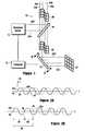
- FIG. 1is a schematic representation of a system for practicing the methods of the present invention
- FIG. 2Ais a sinusoidal illustration of a phase shift of less than 2 ⁇ between a light beam in a distorted wavefront and an idealized light beam of a plane wavefront;
- FIG. 2Bis a sinusoidal illustration of a phase shift of more than 2 ⁇ between a light beam in a distorted wavefront and an idealized light beam of a plane wavefront;
- FIG. 3is a plan view of a portion of a sensor array, including a plurality of sensor reference points;
- FIG. 4Ais a single sensor reference point in the sensor array shown in FIG. 3 detecting a phase shift of less than 2 ⁇ ;
- FIG. 4Bis a single sensor reference point in the sensor array shown in FIG. 3 detecting a phase shift of more than 2 ⁇ ;
- FIG. 5is a plan view of the active mirror of the present invention as seen along the line 5 — 5 in FIG. 1;
- FIG. 6Ais a plan view of an individual facet in the active mirror.
- FIG. 6Bis a cross sectional view of an individual fact in the active mirror as seen along a line 6 B— 6 B in FIG. 6 A.
- the system 10basically includes an active mirror 12 , a wavefront sensor 14 , a beam splitter 16 and a computer 18 .
- the wavefront sensor 14can be of a type well known in the pertinent art, such as a Hartmann-Shack sensor.
- the beam splitter 16 and the computer 18can also be of types well known in the pertinent art.
- the active mirror 12must be selected to have certain characteristics that will become more apparent in light of the disclosure presented herein.
- system 10is to program the active mirror 12 . Specifically, this is done to transform a distorted wavefront 20 , which can be described by the phase differences between contiguous individual light beams 22 , into a plane wavefront 24 wherein all of the contiguous individual light beams 22 are in phase with each other.
- a distorted wavefront 20which can be described by the phase differences between contiguous individual light beams 22
- a plane wavefront 24wherein all of the contiguous individual light beams 22 are in phase with each other.
- the individual contiguous light beams 22 a, 22 b, 22 c and 22 dare considered exemplary.
- system 10is also useful for transforming a plane wavefront 24 into a predetermined distorted wavefront 20 .
- the notions of phase differences and phase shifts for the individual light beams 22are important and will perhaps be best appreciated with reference to FIG. 2 A and FIG. 2 B.
- the sinusoidal characteristic of the light beam 22 ais shown as a function of time. Also shown FIG. 2A is the sinusoidal characteristic of the light beam 22 b. If the light beams 22 a and 22 b were in phase with each other, which they are not in FIG. 2A, the light beam 22 b would be shown superposed on top of the light beam 2 a. As shown, however, the light beams 2 a and 2 b are out-of-phase relative to each other, and this difference in phase is shown as a phase shift 26 .
- the phase shift 26can be thought of as either a difference in time or a difference in distance traveled.
- the light beam 22 awill be at a certain position in free space. Due to the phase shift 26 , however, the light beam 22 b will not be at this same position until the subsequent point in time 30 .
- the magnitude of the phase shift 26 between light beam 22 a and light beam 22 bis less than 2 ⁇ .
- the total phase shift 36 which exists between the light beam 22 a and the light beam 22 cis more than 2 ⁇ .
- the total phase shift 36actually includes a modular phase shift 38 which is equal to 2 ⁇ , and an individual phase shift 40 which is less than 2 ⁇ .
- the total phase shift 36 between any two light beams 22can be expressed as the sum of a modular phase shift 38 which is equal to n2 ⁇ , where “n” is an integer, and an individual phase shift 40 , the so-called modulo 2 ⁇ phase shift, which is less than 2 ⁇ .
- the total phase shift 36 for each light beam 22is determined by comparing it with the corresponding light beam 22 in a plane wavefront.
- the total modular phase shift 38can then be subtracted from the total phase shift 36 to obtain the individual phase shift 40 for the particular light beam 22 .
- the total phase shift 36should be determined.
- a sensor array 42is shown in FIG. 3 which can be incorporated into the wavefront sensor 14 to determine the total phase shifts 36 of each individual light beams 22 in a distorted wavefront 20 .
- the sensor array 42includes a plurality of reference points 44 , of which the reference points 44 a and 44 b are exemplary. As shown, these reference points 44 are arranged in columns and rows which have a length 46 and a width 48 . In a manner known in the pertinent art, when a plane wavefront 24 is detected, each of the individual light beams 22 in the plane wavefront 24 will be directly incident on a respective reference point 44 .
- the respective light beams 22will be diverted from the respective reference point 44 . It happens that for each light beam 22 the magnitude of this diversion from the reference point 44 is proportional to the phase shift between the light beam 22 and its corresponding light beam in a plane wavefront 24 . Thus, the total phase deviation 36 of a light beam 22 can be measured relative to a reference point 44 in the wavefront sensor 14 .
- the sensor reference point 44 ais considered by way of example.
- the light beam 22 awhich is exemplary of a light beam 22 in a plane wavefront 24
- the reference point 44 awill be directly incident on the reference point 44 a.
- would be incident on the ring 52 aand so on.
- the light beam 22 chas a modular phase shift 38 which is equal to 2 ⁇ , as well as an individual phase shift 40 , the light beam 22 c will be incident on the sensor array 42 at the point 22 c ′ which is near reference point 44 b but between the ring 50 and the ring 52 .
- the computer 18is able to account for the respective modular phase shifts 38 and consequently determine an individual phase shift 40 for each of the light beam 22 b and 22 c.
- a similar analysiscan be done for each light beam 22 in a distorted wavefront 20 .
- the modular (n2 ⁇ ) phase shift 38can be easily accounted for. What is then left is the individual phase shift 40 ( ⁇ 2 ⁇ ) for each light beam 22 .
- the individual phase shifts 40are then converted by the computer 18 into signals that can be used to program the active mirror 12 .
- the computer 18converts the computer 18 into signals that can be used to program the active mirror 12 .
- reference point 44 acorresponds to the subarray 53 a of facets 54
- reference point 44 bcorresponds to the subarray 53 b of facets 54 .
- each light beam 22can be associated with a particular subarray 53 of facets 54 of the active mirror 12 .
- each light beam 22includes a plurality of light beams and, therefore, the tilt of each light beam 22 must be mimicked by a plurality of facets 54 . Specifically, for the present invention, this is accomplished by separate subarrays 53 of facets 54 .
- each facet 54 within each subarray 53 of the active mirror 12is shown to have a reflective surface 56 which is supported by four extensions 58 a-d.
- each facet 54is dimensioned to be approximately a forty micron by forty micron square. Accordingly, when the active mirror 12 has a length 46 and a width 48 , each equal to approximately eight millimeters, there will be two hundred facets 54 in each row along the length 46 , and two hundred facets 54 in each column along the width 48 . There are then a total of approximately forty thousand facets 54 in the active mirror 12 .
- the extensions 58 for each facet 54are responsive to signals from the computer 18 to move the reflective surface 56 back and forth along a path as indicated by the arrows 60 in FIG. 6 B. More specifically, the distance of travel for the reflective surface 56 of each facet 54 in one direction is set to be approximately four tenths of a micron. Thus, a complete wavelength (2 ⁇ ), which is approximately eight tenths of a micron, can be accommodated by an individual facet 54 . Consequently, each individual phase shift 40 ( ⁇ 2 ⁇ ) can be accommodated by an individual facet 54 .
- a distorted wavefront 20is directed by beam splitter 16 toward the wavefront sensor 14 .
- Individual light beams 22 in the distorted wavefront 20are then detected by the wavefront sensor 14 , and the total phase shift 36 of each individual light beam 22 , from a corresponding light beam 22 in a plane wavefront 24 , is measured.
- the computer 18accounts for the modular phase shift 38 and, thus, determines an individual phase shift 40 for each individual light beam 22 .
- These individual phase shifts 40are then converted into signals that can be used to program the active mirror 12 . Specifically, a signal that is proportional to the individual phase shift 40 of a particular individual light beam 22 activates a corresponding subarray 53 of facets 54 of the active mirror 12 .
- a plane wavefront 24can be converted into a predetermined distorted wavefront 20 .
- This conversioncan be accomplished simply by preprogramming the active mirror 12 .
- feedback controlcan be achieved to maintain the distorted wavefront 20 .
Landscapes
- Physics & Mathematics (AREA)
- Health & Medical Sciences (AREA)
- Life Sciences & Earth Sciences (AREA)
- Biophysics (AREA)
- Ophthalmology & Optometry (AREA)
- Engineering & Computer Science (AREA)
- Biomedical Technology (AREA)
- Heart & Thoracic Surgery (AREA)
- Medical Informatics (AREA)
- Molecular Biology (AREA)
- Surgery (AREA)
- Animal Behavior & Ethology (AREA)
- General Health & Medical Sciences (AREA)
- Public Health (AREA)
- Veterinary Medicine (AREA)
- General Physics & Mathematics (AREA)
- Optics & Photonics (AREA)
- Mechanical Light Control Or Optical Switches (AREA)
- Eye Examination Apparatus (AREA)
- Mounting And Adjusting Of Optical Elements (AREA)
Abstract
Description
Claims (20)
Priority Applications (3)
| Application Number | Priority Date | Filing Date | Title |
|---|---|---|---|
| US09/512,440US6220707B1 (en) | 2000-02-25 | 2000-02-25 | Method for programming an active mirror to mimic a wavefront |
| EP00309707AEP1156354A3 (en) | 2000-02-25 | 2000-11-02 | Method for programming an active mirror to mimic a wavefront |
| JP2000364151AJP3773415B2 (en) | 2000-02-25 | 2000-11-30 | How to program an active mirror to mimic the wavefront |
Applications Claiming Priority (1)
| Application Number | Priority Date | Filing Date | Title |
|---|---|---|---|
| US09/512,440US6220707B1 (en) | 2000-02-25 | 2000-02-25 | Method for programming an active mirror to mimic a wavefront |
Publications (1)
| Publication Number | Publication Date |
|---|---|
| US6220707B1true US6220707B1 (en) | 2001-04-24 |
Family
ID=24039085
Family Applications (1)
| Application Number | Title | Priority Date | Filing Date |
|---|---|---|---|
| US09/512,440Expired - LifetimeUS6220707B1 (en) | 2000-02-25 | 2000-02-25 | Method for programming an active mirror to mimic a wavefront |
Country Status (3)
| Country | Link |
|---|---|
| US (1) | US6220707B1 (en) |
| EP (1) | EP1156354A3 (en) |
| JP (1) | JP3773415B2 (en) |
Cited By (29)
| Publication number | Priority date | Publication date | Assignee | Title |
|---|---|---|---|---|
| US6382797B1 (en)* | 2000-10-17 | 2002-05-07 | 20/10 Perfect Vision Optische Geraete Gmbh | Aberration-free delivery system |
| US6685319B2 (en) | 2000-09-21 | 2004-02-03 | Visx, Incorporated | Enhanced wavefront ablation system |
| US20040061917A1 (en)* | 2001-01-30 | 2004-04-01 | Yoshihiro Mushika | Variable mirror and information apparatus comprising variable mirror |
| EP1419752A1 (en)* | 2002-11-13 | 2004-05-19 | 20/10 Perfect Vision Optische Geraete GmbH | Closed loop control for intrastromal wavefront-guided ablation |
| EP1473006A1 (en)* | 2003-05-02 | 2004-11-03 | 20/10 Perfect Vision Optische Geraete GmbH | Apparatus for intrastromal refractive surgery |
| US20050149005A1 (en)* | 2002-11-13 | 2005-07-07 | Josef Bille | Closed loop control for intrastromal wavefront-guided ablation with fractionated treatment program |
| US20050152019A1 (en)* | 2002-01-29 | 2005-07-14 | Yoshihiro Mushika | Shape-variable mirror and light control device having the shape-variable mirror |
| US20060061731A1 (en)* | 2004-08-31 | 2006-03-23 | Tobias Kuhn | Systems and methods for shaping wavefronts in polychromatic light using phase shifting elements |
| US20070176077A1 (en)* | 2006-01-30 | 2007-08-02 | Science Applications International Corporation | System and method for correction of turbulence effects on laser or other transmission |
| US7268937B1 (en)* | 2005-05-27 | 2007-09-11 | United States Of America As Represented By The Secretary Of The Air Force | Holographic wavefront sensor |
| US7368846B2 (en) | 2002-11-06 | 2008-05-06 | Matsushita Electric Industrial Co., Ltd. | Microactuator with displacement sensing function and deformable mirror including the microactuator |
| US20100053552A1 (en)* | 2008-09-04 | 2010-03-04 | Bille Josef F | Custom phase plate |
| WO2010102155A1 (en) | 2009-03-04 | 2010-09-10 | Aaren Scientific Inc. | System for forming and modifying lenses and lenses formed thereby |
| US20100245976A1 (en)* | 2006-06-28 | 2010-09-30 | University Of Rochester | Digital binary mems wavefront control |
| US20100274233A1 (en)* | 1999-08-11 | 2010-10-28 | Carl Zeiss Meditec Ag | Method and device for performing online aberrometry in refractive eye correction |
| US20110028950A1 (en)* | 2009-07-29 | 2011-02-03 | Lensx Lasers, Inc. | Optical System for Ophthalmic Surgical Laser |
| US20110028953A1 (en)* | 2009-07-29 | 2011-02-03 | Lensx Lasers, Inc. | Optical System for Ophthalmic Surgical Laser |
| US20110028958A1 (en)* | 2009-07-29 | 2011-02-03 | Lensx Lasers, Inc. | Optical System for Ophthalmic Surgical Laser |
| WO2011017002A3 (en)* | 2009-07-29 | 2011-05-19 | Alcon Lensx, Inc. | Optical system with movable lens for ophthalmic surgical laser |
| US20110118713A1 (en)* | 2009-11-16 | 2011-05-19 | Lensx Lasers, Inc. | Variable Stage Optical System For Ophthalmic Surgical Laser |
| CN102573719A (en)* | 2009-07-29 | 2012-07-11 | 爱尔康蓝斯克斯股份有限公司 | Optical system for ophthalmic surgical laser |
| US8292952B2 (en) | 2009-03-04 | 2012-10-23 | Aaren Scientific Inc. | System for forming and modifying lenses and lenses formed thereby |
| EP2583719A1 (en) | 2011-10-20 | 2013-04-24 | Heidelberg Engineering GmbH | Diagnostic imaging for age-related macular degeneration (AMD) using second harmonic generation (SHG) techniques |
| US8646916B2 (en) | 2009-03-04 | 2014-02-11 | Perfect Ip, Llc | System for characterizing a cornea and obtaining an opthalmic lens |
| US20140063585A1 (en)* | 2012-08-31 | 2014-03-06 | John G. Hagoplan | Phase-controlled magnetic mirror, mirror system, and methods of using the mirror |
| US8764737B2 (en) | 2007-09-06 | 2014-07-01 | Alcon Lensx, Inc. | Precise targeting of surgical photodisruption |
| US8852177B2 (en) | 2012-03-09 | 2014-10-07 | Alcon Lensx, Inc. | Spatio-temporal beam modulator for surgical laser systems |
| US9770362B2 (en) | 2014-12-23 | 2017-09-26 | Novartis Ag | Wavefront correction for ophthalmic surgical lasers |
| US10182943B2 (en) | 2012-03-09 | 2019-01-22 | Alcon Lensx, Inc. | Adjustable pupil system for surgical laser systems |
Citations (7)
| Publication number | Priority date | Publication date | Assignee | Title |
|---|---|---|---|---|
| US4732473A (en) | 1984-06-14 | 1988-03-22 | Josef Bille | Apparatus for, and methods of, determining the characteristics of semi-conductor wafers |
| US5062702A (en) | 1990-03-16 | 1991-11-05 | Intelligent Surgical Lasers, Inc. | Device for mapping corneal topography |
| US5777719A (en) | 1996-12-23 | 1998-07-07 | University Of Rochester | Method and apparatus for improving vision and the resolution of retinal images |
| US6002484A (en)* | 1999-06-18 | 1999-12-14 | Rozema; Jos J. | Phase contrast aberroscope |
| US6007204A (en)* | 1998-06-03 | 1999-12-28 | Welch Allyn, Inc. | Compact ocular measuring system |
| US6050687A (en)* | 1999-06-11 | 2000-04-18 | 20/10 Perfect Vision Optische Geraete Gmbh | Method and apparatus for measurement of the refractive properties of the human eye |
| US6086204A (en)* | 1999-09-20 | 2000-07-11 | Magnante; Peter C. | Methods and devices to design and fabricate surfaces on contact lenses and on corneal tissue that correct the eye's optical aberrations |
Family Cites Families (2)
| Publication number | Priority date | Publication date | Assignee | Title |
|---|---|---|---|---|
| US5109349A (en)* | 1990-01-23 | 1992-04-28 | Kaman Aerospace Corporation | Actively controlled segmented mirror |
| US5936720A (en)* | 1996-07-10 | 1999-08-10 | Neal; Daniel R. | Beam characterization by wavefront sensor |
- 2000
- 2000-02-25USUS09/512,440patent/US6220707B1/ennot_activeExpired - Lifetime
- 2000-11-02EPEP00309707Apatent/EP1156354A3/ennot_activeCeased
- 2000-11-30JPJP2000364151Apatent/JP3773415B2/ennot_activeExpired - Fee Related
Patent Citations (9)
| Publication number | Priority date | Publication date | Assignee | Title |
|---|---|---|---|---|
| US4732473A (en) | 1984-06-14 | 1988-03-22 | Josef Bille | Apparatus for, and methods of, determining the characteristics of semi-conductor wafers |
| US5062702A (en) | 1990-03-16 | 1991-11-05 | Intelligent Surgical Lasers, Inc. | Device for mapping corneal topography |
| US5777719A (en) | 1996-12-23 | 1998-07-07 | University Of Rochester | Method and apparatus for improving vision and the resolution of retinal images |
| US5949521A (en) | 1996-12-23 | 1999-09-07 | University Of Rochester | Method and apparatus for improving vision and the resolution of retinal images |
| US6007204A (en)* | 1998-06-03 | 1999-12-28 | Welch Allyn, Inc. | Compact ocular measuring system |
| US6050687A (en)* | 1999-06-11 | 2000-04-18 | 20/10 Perfect Vision Optische Geraete Gmbh | Method and apparatus for measurement of the refractive properties of the human eye |
| US6155684A (en)* | 1999-06-11 | 2000-12-05 | Perfect Vision Optische Geraete Gmbh | Method and apparatus for precompensating the refractive properties of the human eye with adaptive optical feedback control |
| US6002484A (en)* | 1999-06-18 | 1999-12-14 | Rozema; Jos J. | Phase contrast aberroscope |
| US6086204A (en)* | 1999-09-20 | 2000-07-11 | Magnante; Peter C. | Methods and devices to design and fabricate surfaces on contact lenses and on corneal tissue that correct the eye's optical aberrations |
Non-Patent Citations (9)
| Title |
|---|
| Baker, Holographic Contour Analysis of the Cornea, pp. 426-437, SPIE, vol. 1161, New Methods in Microscopy and Low Light Imaging (1989).* |
| Bille et al., Imaging of the Retina by Scanning Laser Topography, pp. 417-425, SPIE, vol. 1161, New Methods in Microscopy and Low Light Imaging (1989).* |
| Cubalchini, Modal Wave-Front Estimation from Phase Derivative Measurements, pp. ?, Hughes Aircraft Co., Nov. 6, 1978. |
| Freischlad et al., Modal Estimation of a Wave Front From Difference Measurements Using the Discrete Fourier Transform, J. Opt. Soc. Am, vol. 3, No. 11, Nov. 1986.* |
| Klyce et al., Imaging, Reconstruction, and Display of Corneal Topography, pp. 409-416, SPIE, vol. 1161, New Methods in Microscopy and Low Light Imaging (1989).* |
| Liang et al., Objective Measurement of Wave Aberrations of the Human Eye with the Use of a Hartmann-Shack Wave-Front Sensor, pp. 1949-1957, J. Opt. Soc. Am., vol. 11, No. 7, Jul. 1994.* |
| Southwell, Wave-Front Estimation from Wave-Front Slope Measurements, pp. 998-1005, J. Opt. Soc. Am., vol. 70, No. 8, Aug. 1980.* |
| Walsh et al., Objective Technique for the Determination of Monochromatic Aberrations of the Human Eye, pp. 987-992, J. Opt. Soc. Am., vol. 1, No. 9, Sep. 1984.* |
| Wang, Wave-Front Interpretation with Zernike Polynomials, pp. 1510-1518, Applied Optics, vol. 9, No. 9, May 1, 1980. |
Cited By (68)
| Publication number | Priority date | Publication date | Assignee | Title |
|---|---|---|---|---|
| US20100274233A1 (en)* | 1999-08-11 | 2010-10-28 | Carl Zeiss Meditec Ag | Method and device for performing online aberrometry in refractive eye correction |
| US8029136B2 (en) | 1999-08-11 | 2011-10-04 | Carl Zeiss Meditec Ag | Method and device for performing online aberrometry in refractive eye correction |
| US8356897B2 (en) | 1999-08-11 | 2013-01-22 | Carl Zeiss Meditec Ag | Method and device for performing online aberrometry in refractive eye correction |
| US6685319B2 (en) | 2000-09-21 | 2004-02-03 | Visx, Incorporated | Enhanced wavefront ablation system |
| US6382797B1 (en)* | 2000-10-17 | 2002-05-07 | 20/10 Perfect Vision Optische Geraete Gmbh | Aberration-free delivery system |
| US20040061917A1 (en)* | 2001-01-30 | 2004-04-01 | Yoshihiro Mushika | Variable mirror and information apparatus comprising variable mirror |
| US20050168798A1 (en)* | 2001-01-30 | 2005-08-04 | Matsushita Electric Industrial Co., Ltd. | Deformable mirror and information device having the deformable mirror |
| US6952304B2 (en) | 2001-01-30 | 2005-10-04 | Matsushita Electric Industrial Co., Ltd. | Variable mirror and information apparatus comprising variable mirror |
| US6995897B2 (en) | 2001-01-30 | 2006-02-07 | Matsushita Electric Industrial Co., Ltd. | Deformable mirror and information device having the deformable mirror |
| US7068415B2 (en) | 2002-01-29 | 2006-06-27 | Matsushita Electric Industrial Co., Ltd. | Deformable mirror and optical controller including the deformable mirror |
| US20050152019A1 (en)* | 2002-01-29 | 2005-07-14 | Yoshihiro Mushika | Shape-variable mirror and light control device having the shape-variable mirror |
| US7635939B2 (en) | 2002-11-06 | 2009-12-22 | Panasonic Corporation | Microactuator with displacement sensing function and deformable mirror including the microactuator |
| US7368846B2 (en) | 2002-11-06 | 2008-05-06 | Matsushita Electric Industrial Co., Ltd. | Microactuator with displacement sensing function and deformable mirror including the microactuator |
| US20080231141A1 (en)* | 2002-11-06 | 2008-09-25 | Matsushita Electric Industrial Co., Ltd. | Microactuator with Displacement Sensing Function and Deformable Mirror Including the Microactuator |
| US20050149005A1 (en)* | 2002-11-13 | 2005-07-07 | Josef Bille | Closed loop control for intrastromal wavefront-guided ablation with fractionated treatment program |
| EP1419752A1 (en)* | 2002-11-13 | 2004-05-19 | 20/10 Perfect Vision Optische Geraete GmbH | Closed loop control for intrastromal wavefront-guided ablation |
| US7232436B2 (en)* | 2002-11-13 | 2007-06-19 | Josef Bille | Closed loop control for intrastromal wavefront-guided ablation with fractionated treatment program |
| EP1473006A1 (en)* | 2003-05-02 | 2004-11-03 | 20/10 Perfect Vision Optische Geraete GmbH | Apparatus for intrastromal refractive surgery |
| US20060061731A1 (en)* | 2004-08-31 | 2006-03-23 | Tobias Kuhn | Systems and methods for shaping wavefronts in polychromatic light using phase shifting elements |
| US7360893B2 (en)* | 2004-08-31 | 2008-04-22 | 20/10 Perfect Vision Optische Geraete Gmbh | Systems and methods for shaping wavefronts in polychromatic light using phase shifting elements |
| WO2006024911A3 (en)* | 2004-08-31 | 2006-05-11 | 20 10 Perfect Vision Optische | Systems and methods for shaping wavefronts in polychromatic light using phase shifting elements |
| US7268937B1 (en)* | 2005-05-27 | 2007-09-11 | United States Of America As Represented By The Secretary Of The Air Force | Holographic wavefront sensor |
| WO2007089402A3 (en)* | 2006-01-30 | 2008-06-05 | Science Applic Int Corp | System and method for correction of turbulence effects on laser or other transmission |
| US7402785B2 (en) | 2006-01-30 | 2008-07-22 | Science Applications International Corporation | System and method for correction of turbulence effects on laser or other transmission |
| US20070176077A1 (en)* | 2006-01-30 | 2007-08-02 | Science Applications International Corporation | System and method for correction of turbulence effects on laser or other transmission |
| US8107156B2 (en) | 2006-06-28 | 2012-01-31 | University Of Rochester | Digital binary MEMS wavefront control |
| US20100245976A1 (en)* | 2006-06-28 | 2010-09-30 | University Of Rochester | Digital binary mems wavefront control |
| US9044303B2 (en) | 2007-09-06 | 2015-06-02 | Alcon Lensx, Inc. | Precise targeting of surgical photodisruption |
| US9408749B2 (en) | 2007-09-06 | 2016-08-09 | Alcon Lensx, Inc. | Precise targeting of surgical photodisruption |
| US8764737B2 (en) | 2007-09-06 | 2014-07-01 | Alcon Lensx, Inc. | Precise targeting of surgical photodisruption |
| US20100053552A1 (en)* | 2008-09-04 | 2010-03-04 | Bille Josef F | Custom phase plate |
| US8020994B2 (en) | 2008-09-04 | 2011-09-20 | Heidelberg Engineering Gmbh | Custom phase plate |
| CN102939044B (en)* | 2009-03-04 | 2016-01-20 | 完美Ip有限公司 | System for Characterizing the Cornea and Fabricating Ophthalmic Lenses |
| US8568627B2 (en) | 2009-03-04 | 2013-10-29 | Perfect Ip, Llc | Method for forming and modifying lenses |
| CN105147239A (en)* | 2009-03-04 | 2015-12-16 | 完美Ip有限公司 | System for characterizing a cornea and obtaining an ophthalmic lens |
| CN102939044A (en)* | 2009-03-04 | 2013-02-20 | 安伦科技股份有限公司 | System for Characterizing the Cornea and Fabricating Ophthalmic Lenses |
| US20110128501A1 (en)* | 2009-03-04 | 2011-06-02 | Bille Josef F | System for characterizing a cornea and obtaining an ophthalmic lens |
| US20110130677A1 (en)* | 2009-03-04 | 2011-06-02 | Bille Josef F | System for characterizing a conrea and obtaining an ophthalmic lens |
| US20110212205A1 (en)* | 2009-03-04 | 2011-09-01 | Bille Josef F | System for forming and modifying lenses and lenses formed thereby |
| US20110210459A1 (en)* | 2009-03-04 | 2011-09-01 | Bille Josef F | System for forming and modifying lenses and lenses formed thereby |
| US8646916B2 (en) | 2009-03-04 | 2014-02-11 | Perfect Ip, Llc | System for characterizing a cornea and obtaining an opthalmic lens |
| WO2010102156A1 (en) | 2009-03-04 | 2010-09-10 | Aaren Scientific Inc. | System for characterizing a cornea and obtaining an ophthalmic lens |
| WO2010102155A1 (en) | 2009-03-04 | 2010-09-10 | Aaren Scientific Inc. | System for forming and modifying lenses and lenses formed thereby |
| US8152302B2 (en) | 2009-03-04 | 2012-04-10 | Aaren Scientific, Inc. | System for characterizing a cornea and obtaining an ophthalmic lens |
| US8292952B2 (en) | 2009-03-04 | 2012-10-23 | Aaren Scientific Inc. | System for forming and modifying lenses and lenses formed thereby |
| WO2011017002A3 (en)* | 2009-07-29 | 2011-05-19 | Alcon Lensx, Inc. | Optical system with movable lens for ophthalmic surgical laser |
| US20110028952A1 (en)* | 2009-07-29 | 2011-02-03 | Lensx Lasers, Inc. | Optical System with Multiple Scanners for Ophthalmic Surgical Laser |
| US8262647B2 (en) | 2009-07-29 | 2012-09-11 | Alcon Lensx, Inc. | Optical system for ophthalmic surgical laser |
| CN102573719A (en)* | 2009-07-29 | 2012-07-11 | 爱尔康蓝斯克斯股份有限公司 | Optical system for ophthalmic surgical laser |
| US20110028954A1 (en)* | 2009-07-29 | 2011-02-03 | Lensx Lasers, Inc. | Optical System for Ophthalmic Surgical Laser |
| US8419721B2 (en) | 2009-07-29 | 2013-04-16 | Alcon Lensx, Inc. | Optical system for ophthalmic surgical laser |
| US8267925B2 (en) | 2009-07-29 | 2012-09-18 | Alcon Lensx, Inc. | Optical system for ophthalmic surgical laser |
| US8500725B2 (en) | 2009-07-29 | 2013-08-06 | Alcon Lensx, Inc. | Optical system for ophthalmic surgical laser |
| US20110028957A1 (en)* | 2009-07-29 | 2011-02-03 | Lensx Lasers, Inc. | Optical System for Ophthalmic Surgical Laser |
| US20110028948A1 (en)* | 2009-07-29 | 2011-02-03 | Lensx Lasers, Inc. | Optical System for Ophthalmic Surgical Laser |
| US20110028958A1 (en)* | 2009-07-29 | 2011-02-03 | Lensx Lasers, Inc. | Optical System for Ophthalmic Surgical Laser |
| US9504608B2 (en) | 2009-07-29 | 2016-11-29 | Alcon Lensx, Inc. | Optical system with movable lens for ophthalmic surgical laser |
| US8679100B2 (en) | 2009-07-29 | 2014-03-25 | Alcon Lensx, Inc. | Optical system with multiple scanners for ophthalmic surgical laser |
| US20110028953A1 (en)* | 2009-07-29 | 2011-02-03 | Lensx Lasers, Inc. | Optical System for Ophthalmic Surgical Laser |
| US20110028950A1 (en)* | 2009-07-29 | 2011-02-03 | Lensx Lasers, Inc. | Optical System for Ophthalmic Surgical Laser |
| US8920407B2 (en) | 2009-07-29 | 2014-12-30 | Alcon Lensx, Inc. | Optical system for ophthalmic surgical laser |
| US8506559B2 (en) | 2009-11-16 | 2013-08-13 | Alcon Lensx, Inc. | Variable stage optical system for ophthalmic surgical laser |
| US20110118713A1 (en)* | 2009-11-16 | 2011-05-19 | Lensx Lasers, Inc. | Variable Stage Optical System For Ophthalmic Surgical Laser |
| EP2583719A1 (en) | 2011-10-20 | 2013-04-24 | Heidelberg Engineering GmbH | Diagnostic imaging for age-related macular degeneration (AMD) using second harmonic generation (SHG) techniques |
| US8852177B2 (en) | 2012-03-09 | 2014-10-07 | Alcon Lensx, Inc. | Spatio-temporal beam modulator for surgical laser systems |
| US10182943B2 (en) | 2012-03-09 | 2019-01-22 | Alcon Lensx, Inc. | Adjustable pupil system for surgical laser systems |
| US20140063585A1 (en)* | 2012-08-31 | 2014-03-06 | John G. Hagoplan | Phase-controlled magnetic mirror, mirror system, and methods of using the mirror |
| US9770362B2 (en) | 2014-12-23 | 2017-09-26 | Novartis Ag | Wavefront correction for ophthalmic surgical lasers |
Also Published As
| Publication number | Publication date |
|---|---|
| JP3773415B2 (en) | 2006-05-10 |
| EP1156354A3 (en) | 2003-10-08 |
| EP1156354A2 (en) | 2001-11-21 |
| JP2001242394A (en) | 2001-09-07 |
Similar Documents
| Publication | Publication Date | Title |
|---|---|---|
| US6220707B1 (en) | Method for programming an active mirror to mimic a wavefront | |
| US8345262B2 (en) | Method and apparatus for determining a deviation of an actual shape from a desired shape of an optical surface | |
| EP2634551B1 (en) | Interferometer and fourier-transform spectroscopic analyzer | |
| CA1121625A (en) | Optical scanner using plane linear diffraction gratings on a rotating spinner | |
| US8362410B2 (en) | Source-independent beam director and control system for a high-energy electromagnetic radiation source | |
| US4272190A (en) | Optical measuring system | |
| US6649895B1 (en) | Dispersed Hartmann sensor and method for mirror segment alignment and phasing | |
| EP2314203A1 (en) | Adaptive optics apparatus and imaging apparatus including the same | |
| US11530982B2 (en) | Method and Fourier Transformation spectrometer with double beam interferometer for Single Shot Imaging Fourier Spectroscopy | |
| JPH11318827A (en) | Method and device for simultaneously measuring length of eyeball and ametropia | |
| DE102011082156A1 (en) | Optical position measuring device | |
| CN104903678A (en) | Integrated wavefront sensor and profilometer | |
| JP2000136909A (en) | Geometrically desensitized interferometer with optics with high stray light handling capability | |
| CN108845415A (en) | A kind of method and detection system that the thick common phase applied to splicing mirror is adjusted | |
| JP6203008B2 (en) | Adaptive optical system and imaging apparatus | |
| US12111421B2 (en) | Waveguide-based transmitters with adjustable lighting | |
| DE60200349T2 (en) | Wavelength tunable laser with a diffractive optical element | |
| JPH11510251A (en) | Interferometer with composite optical element | |
| Vdovin | Optimization-based operation of micromachined deformable mirrors | |
| US7791737B2 (en) | Method and apparatus for interferometrically measuring the shape of a test object | |
| JP2008089356A (en) | Aspherical surface measuring element, optical interference measuring apparatus and method using the aspherical surface measuring element, aspherical surface shape correcting method, and system error correcting method | |
| US4958931A (en) | System utilizing an achromatic null lens for correcting aberrations in a spherical wavefront | |
| Löfdahl et al. | Calibration of a deformable mirror and Strehl ratio measurements by use of phase diversity | |
| DE102011005937B4 (en) | Device for interferential distance measurement | |
| DE3852649T2 (en) | Straightness interferometer. |
Legal Events
| Date | Code | Title | Description |
|---|---|---|---|
| AS | Assignment | Owner name:20/10 PERFECT VISION OPTISCHE GERAETE GMBH, GERMAN Free format text:ASSIGNMENT OF ASSIGNORS INTEREST;ASSIGNOR:BILLE, JOSEF;REEL/FRAME:010918/0136 Effective date:20000222 | |
| STCF | Information on status: patent grant | Free format text:PATENTED CASE | |
| FPAY | Fee payment | Year of fee payment:4 | |
| FPAY | Fee payment | Year of fee payment:8 | |
| AS | Assignment | Owner name:20/10 PERFECT VISION AG, GERMANY Free format text:CHANGE OF NAME;ASSIGNOR:20/10 PERFECT VISION OPTISCHE GERAETE GMBH;REEL/FRAME:023056/0389 Effective date:20071108 Owner name:20/10 PERFECT VISION AG,GERMANY Free format text:CHANGE OF NAME;ASSIGNOR:20/10 PERFECT VISION OPTISCHE GERAETE GMBH;REEL/FRAME:023056/0389 Effective date:20071108 | |
| AS | Assignment | Owner name:20/10 PERFECT VISION OPERATIONS GMBH, GERMANY Free format text:CHANGE OF NAME;ASSIGNOR:20/10 PERFECT VISION AG;REEL/FRAME:023065/0012 Effective date:20090428 Owner name:20/10 PERFECT VISION OPERATIONS GMBH,GERMANY Free format text:CHANGE OF NAME;ASSIGNOR:20/10 PERFECT VISION AG;REEL/FRAME:023065/0012 Effective date:20090428 | |
| AS | Assignment | Owner name:TECHNOLAS PERFECT VISION GMBH, GERMANY Free format text:CHANGE OF NAME;ASSIGNOR:20/10 PERFECT VISION OPERATIONS GMBH;REEL/FRAME:023065/0970 Effective date:20090428 Owner name:TECHNOLAS PERFECT VISION GMBH,GERMANY Free format text:CHANGE OF NAME;ASSIGNOR:20/10 PERFECT VISION OPERATIONS GMBH;REEL/FRAME:023065/0970 Effective date:20090428 | |
| AS | Assignment | Owner name:TECHNOLAS PERFECT VISION GMBH, GERMANY Free format text:ASSIGNMENT OF ASSIGNORS INTEREST;ASSIGNOR:20/10 PERFECT VISION AG;REEL/FRAME:023510/0024 Effective date:20091106 Owner name:TECHNOLAS PERFECT VISION GMBH,GERMANY Free format text:ASSIGNMENT OF ASSIGNORS INTEREST;ASSIGNOR:20/10 PERFECT VISION AG;REEL/FRAME:023510/0024 Effective date:20091106 | |
| FEPP | Fee payment procedure | Free format text:PAT HOLDER NO LONGER CLAIMS SMALL ENTITY STATUS, ENTITY STATUS SET TO UNDISCOUNTED (ORIGINAL EVENT CODE: STOL); ENTITY STATUS OF PATENT OWNER: LARGE ENTITY | |
| SULP | Surcharge for late payment | ||
| FPAY | Fee payment | Year of fee payment:12 | |
| AS | Assignment | Owner name:BARCLAYS BANK PLC, AS COLLATERAL AGENT, NEW YORK Free format text:SECURITY AGREEMENT;ASSIGNORS:TECHNOLAS PERFECT VISION GMBH;DR. GERHARD MANN CHEM-PHARM. FABRIK GMBH;REEL/FRAME:036400/0711 Effective date:20150819 | |
| AS | Assignment | Owner name:THE BANK OF NEW YORK MELLON, NEW YORK Free format text:SECURITY INTEREST;ASSIGNOR:TECHNOLAS PERFECT VISION GMBH;REEL/FRAME:043251/0910 Effective date:20170717 | |
| AS | Assignment | Owner name:THE BANK OF NEW YORK MELLON, AS COLLATERAL AGENT, NEW YORK Free format text:SECURITY INTEREST;ASSIGNORS:ATON PHARMA, INC.;BAUSCH & LOMB INCORPORATED;BAUSCH & LOMB PHARMA HOLDINGS CORP.;AND OTHERS;REEL/FRAME:045444/0634 Effective date:20180213 Owner name:BARCLAYS BANK PLC, AS COLLATERAL AGENT, NEW YORK Free format text:SECURITY INTEREST;ASSIGNORS:ATON PHARMA, INC.;BAUSCH & LOMB INCORPORATED;BAUSCH & LOMB PHARMA HOLDINGS CORP.;AND OTHERS;REEL/FRAME:045444/0299 Effective date:20180213 Owner name:THE BANK OF NEW YORK MELLON, AS COLLATERAL AGENT, Free format text:SECURITY INTEREST;ASSIGNORS:ATON PHARMA, INC.;BAUSCH & LOMB INCORPORATED;BAUSCH & LOMB PHARMA HOLDINGS CORP.;AND OTHERS;REEL/FRAME:045444/0634 Effective date:20180213 | |
| AS | Assignment | Owner name:THE BANK OF NEW YORK MELLON, AS COLLATERAL AGENT, Free format text:INTELLECTUAL PROPERTY SECURITY AGREEMENT;ASSIGNORS:BAUSCH HEALTH IRELAND LIMITED;BAUSCH HEALTH COMPANIES INC.;BAUSCH HEALTH, CANADA INC.;AND OTHERS;REEL/FRAME:049672/0652 Effective date:20190701 Owner name:THE BANK OF NEW YORK MELLON, AS COLLATERAL AGENT, NEW YORK Free format text:INTELLECTUAL PROPERTY SECURITY AGREEMENT;ASSIGNORS:BAUSCH HEALTH IRELAND LIMITED;BAUSCH HEALTH COMPANIES INC.;BAUSCH HEALTH, CANADA INC.;AND OTHERS;REEL/FRAME:049672/0652 Effective date:20190701 | |
| AS | Assignment | Owner name:LABORATOIRE CHAUVIN S.A.S., FRANCE Free format text:RELEASE OF SECURITY INTEREST IN SPECIFIED PATENTS (REEL/FRAME 045444/0299);ASSIGNOR:BARCLAYS BANK PLC;REEL/FRAME:061779/0001 Effective date:20221019 Owner name:PF CONSUMER HEALTHCARE 1 LLC, DELAWARE Free format text:RELEASE OF SECURITY INTEREST IN SPECIFIED PATENTS (REEL/FRAME 045444/0299);ASSIGNOR:BARCLAYS BANK PLC;REEL/FRAME:061779/0001 Effective date:20221019 Owner name:THE UNITED STATES OF AMERICA, AS REPRESENTED BY THE SECRETARY, DEPARTMENT OF HEALTH AND HUMAN SERVICES, MARYLAND Free format text:RELEASE OF SECURITY INTEREST IN SPECIFIED PATENTS (REEL/FRAME 045444/0299);ASSIGNOR:BARCLAYS BANK PLC;REEL/FRAME:061779/0001 Effective date:20221019 Owner name:TECHNOLAS PERFECT VISION GMBH, GERMANY Free format text:RELEASE OF SECURITY INTEREST IN SPECIFIED PATENTS (REEL/FRAME 045444/0299);ASSIGNOR:BARCLAYS BANK PLC;REEL/FRAME:061779/0001 Effective date:20221019 Owner name:BAUSCH & LOMB INCORPORATED, NEW YORK Free format text:RELEASE OF SECURITY INTEREST IN SPECIFIED PATENTS (REEL/FRAME 045444/0299);ASSIGNOR:BARCLAYS BANK PLC;REEL/FRAME:061779/0001 Effective date:20221019 | |
| AS | Assignment | Owner name:THE UNITED STATES OF AMERICA, AS REPRESENTED BY THE SECRETARY, DEPARTMENT OF HEALTH AND HUMAN SERVICES, MARYLAND Free format text:OMNIBUS PATENT SECURITY RELEASE AGREEMENT (REEL/FRAME 045444/0634);ASSIGNOR:THE BANK OF NEW YORK MELLON;REEL/FRAME:061872/0295 Effective date:20221018 Owner name:TECHNOLAS PERFECT VISION GMBH, GERMANY Free format text:OMNIBUS PATENT SECURITY RELEASE AGREEMENT (REEL/FRAME 045444/0634);ASSIGNOR:THE BANK OF NEW YORK MELLON;REEL/FRAME:061872/0295 Effective date:20221018 Owner name:LABORATOIRE CHAUVIN S.A.S., FRANCE Free format text:OMNIBUS PATENT SECURITY RELEASE AGREEMENT (REEL/FRAME 045444/0634);ASSIGNOR:THE BANK OF NEW YORK MELLON;REEL/FRAME:061872/0295 Effective date:20221018 Owner name:BAUSCH & LOMB INCORPORATED, NEW YORK Free format text:OMNIBUS PATENT SECURITY RELEASE AGREEMENT (REEL/FRAME 045444/0634);ASSIGNOR:THE BANK OF NEW YORK MELLON;REEL/FRAME:061872/0295 Effective date:20221018 |