US6219711B1 - Synchronous communication interface - Google Patents
Synchronous communication interfaceDownload PDFInfo
- Publication number
- US6219711B1 US6219711B1US08/943,355US94335597AUS6219711B1US 6219711 B1US6219711 B1US 6219711B1US 94335597 AUS94335597 AUS 94335597AUS 6219711 B1US6219711 B1US 6219711B1
- Authority
- US
- United States
- Prior art keywords
- module
- request
- synchronous
- data
- network
- Prior art date
- Legal status (The legal status is an assumption and is not a legal conclusion. Google has not performed a legal analysis and makes no representation as to the accuracy of the status listed.)
- Expired - Lifetime
Links
Images


Classifications
- H—ELECTRICITY
- H04—ELECTRIC COMMUNICATION TECHNIQUE
- H04L—TRANSMISSION OF DIGITAL INFORMATION, e.g. TELEGRAPHIC COMMUNICATION
- H04L41/00—Arrangements for maintenance, administration or management of data switching networks, e.g. of packet switching networks
- H04L41/02—Standardisation; Integration
- H04L41/0213—Standardised network management protocols, e.g. simple network management protocol [SNMP]
- G—PHYSICS
- G06—COMPUTING OR CALCULATING; COUNTING
- G06F—ELECTRIC DIGITAL DATA PROCESSING
- G06F13/00—Interconnection of, or transfer of information or other signals between, memories, input/output devices or central processing units
- G06F13/38—Information transfer, e.g. on bus
- G06F13/40—Bus structure
- G06F13/4063—Device-to-bus coupling
- G06F13/4068—Electrical coupling
- G06F13/4081—Live connection to bus, e.g. hot-plugging
- H—ELECTRICITY
- H04—ELECTRIC COMMUNICATION TECHNIQUE
- H04L—TRANSMISSION OF DIGITAL INFORMATION, e.g. TELEGRAPHIC COMMUNICATION
- H04L41/00—Arrangements for maintenance, administration or management of data switching networks, e.g. of packet switching networks
- H04L41/06—Management of faults, events, alarms or notifications
- H04L41/0604—Management of faults, events, alarms or notifications using filtering, e.g. reduction of information by using priority, element types, position or time
- H—ELECTRICITY
- H04—ELECTRIC COMMUNICATION TECHNIQUE
- H04L—TRANSMISSION OF DIGITAL INFORMATION, e.g. TELEGRAPHIC COMMUNICATION
- H04L41/00—Arrangements for maintenance, administration or management of data switching networks, e.g. of packet switching networks
- H04L41/08—Configuration management of networks or network elements
- H—ELECTRICITY
- H04—ELECTRIC COMMUNICATION TECHNIQUE
- H04L—TRANSMISSION OF DIGITAL INFORMATION, e.g. TELEGRAPHIC COMMUNICATION
- H04L41/00—Arrangements for maintenance, administration or management of data switching networks, e.g. of packet switching networks
- H04L41/22—Arrangements for maintenance, administration or management of data switching networks, e.g. of packet switching networks comprising specially adapted graphical user interfaces [GUI]
Definitions
- Appendix Awhich forms a part of this disclosure, is a list of commonly owned copending U.S. patent applications. Each one of the applications listed in Appendix A is hereby incorporated herein in its entirety by reference thereto.
- the present inventionrelates generally to the field of computer communications.
- the present inventionrelates to an apparatus for performing synchronous operations in an asynchronous communications environment.
- a plurality of linked computersis now commonplace in businesses and organizations.
- Such networksinclude Local Area Networks (“LAN”) or Wide Area Networks (“WAN”) which are interconnected with ethernet, twisted pair, fiber optics or token ring communications hardware.
- LANLocal Area Networks
- WANWide Area Networks
- Computers in such networksoften interact by relying on what is called the client-server model.
- communicationtakes the form of request-response pairs.
- clienta program at one location sends a request to a program at another location and waits for a response.
- the requesting programis called the “client,” and the program which responds to the request is called the “server.”
- One client-server communication systemis the Simple Network Management Protocol (“the SNMP system”).
- the SNMP systemeach client transmits requests to, and receives responses from, one or more servers connected to the SNMP system.
- Each serverprocesses its respective requests, and if needed, sends responses back to the clients.
- the requests and responses generated by the clients and serversare often generally referred to as network messages, network communications, data packets, and the like.
- client requestsare often sent asynchronously. That is, the requests are processed independently and not necessarily in the same order. For example, a particular server may process one request faster than another request. In addition, some servers may execute faster than other servers.
- a clientoften continues to generate additional requests while awaiting the response to outstanding requests. For example, assume that a client generates a first request. While a server processes the first request, the client can continue to generate additional requests. Indeed, the number of outstanding requests is not limited, and can often exceed hundreds or thousands of requests.
- Multiple outstanding requests in an asynchronous networking systemsignificantly add to software development complexity. For example, when a client initiates multiple outstanding requests, the client must track the status of the requests. In some instances, due to server failure, a request may not be processed. In such instances, a new request may need to be generated.
- the clientwhen the client receives a response, the client must ensure that the response is matched with the corresponding request. For instance, a server may respond to the tenth request before responding to the first request. Thus, when the client receives the response, the client must match the response with the corresponding tenth request. As can be appreciated, the complexities of tracking requests can result in errors when a response is not properly matched with a corresponding request.
- Another drawback of conventional asynchronous networking systemsoccurs when a client application attempts to display the responses to multiple requests. For example, assume that a user executes a program to monitor the operational status of different network components. Such a program is often called a system management application.
- the system management applicationmay generate a number of asynchronous requests for information about the different network components.
- the system administration applicationwill receive the responses in a different order than the requests.
- the system administration applicationmay begin to display the responses in a manner which confuses the user. For example, information about the tenth component might be displayed before information about the first component. When viewing this information, a user may in some cases, see data fields which contain partial information, or no information at all.
- the present inventionprovides a synchronous interface module which permits an application program to use a synchronous request for data in an asynchronous communications environment.
- the interface modulecontains a send request module, a monitoring module, and a receive data module.
- the send request modulemakes a request for data using a request that causes the data to return asynchronously.
- the monitoring modulesuspends operation of the interface module until the requested data is available.
- the receive data moduleretrieves the data which was obtained in response to the send request module for the interface module so that the interface module may provide the data to the application module via a synchronous communication.
- the interfacecomprises an apparatus for emulating a synchronous network transaction comprising an application module and an accept request module, both of which are in communication with one another.
- the application moduleincludes a routine to make a data request to the accept request module so that the accept request module may receive the data request from the application module.
- a conversion moduleis also in communication with the accept request module to thereby obtain the data to satisfy the data request over an asynchronous network using one or more network communication modules.
- the conversion moduleis further configured to respond to the application module's request in a single response.
- a network communication moduleis included and is configured to provide the items of data to the conversion module using tools which provide the data in an asynchronous manner.
- FIG. 1illustrates a block diagram of a computer network appropriate for use with one embodiment of the invention
- FIG. 2illustrates a high-level block diagram of the modules in one embodiment of the present invention
- FIG. 3illustrates the module-level architecture of one embodiment of the invention
- FIG. 4illustrates a flow chart of the synchronous emulation process in one embodiment of the invention.
- FIG. 5illustrates a detailed flow chart of the synchronous emulation process in one embodiment of the invention.
- FIG. 6shows an exemplary computer system that implements one embodiment of the invention.
- one embodiment of the inventionprovides an unique synchronous interface which configures an asynchronous networking system to emulate a synchronous networking system.
- the unique synchronous interfacemakes an asynchronous system appear to operate like a synchronous system.
- a synchronous networking systemprocesses requests in an orderly fashion. For example, in many synchronous systems, after initiating a request, the client ceases execution until the server responds. When the client receives the response, the client may then initiate another request. Thus, each request is processed before execution of the next request.
- an applicationdesires to send to a server, two requests to obtain two data values.
- the client applicationmay send both requests before receiving any responses. The responses are then received in any order.
- the applicationsends the first request for the first data value and waits for the response. After receiving the response, the client application then sends the second request for the second data value.
- an applicationdoes not need to monitor and manage multiple outstanding requests. As a result, applications which are designed for a synchronous network system are much simpler and easier to develop.
- Such applicationscommunicate with the unique synchronous interface to initiate a synchronous transaction.
- the unique synchronous interfaceperforms the tasks necessary to emulate the synchronous transaction process while actually performing a transaction on an asynchronous network.
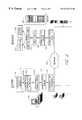
- FIG. 1illustrates an architectural overview of a computer system 100 appropriate for use with one embodiment of the present invention.
- the computer system 100includes one or more client computer(s) 102 and one or more server computer(s) 104 connected by at least one network 106 .
- the client and server computers 102 and 104are multi-processor Pentium-based computers having 256 megabytes or more of RAM. It will be apparent to those of ordinary skill in the art, however, that the client and server computers 102 and 104 may be any conventional general purpose single- or multi-chip microprocessor such as a Pentium processor, a Pentium Pro processor, aa 8051 processor, a MIPS processor, a Power PC processor, an ALPHA processor, etc.
- the network 106can be implemented as a wide area network (“WAN”) or a local area network (“LAN”).
- the network 106allows client users (i.e., users of the client computers 102 ) dispersed over a geographic area to access the server computers 104 .
- the network 106is implemented with a standardized communication protocol known as the Simple Network Management Protocol (“SNMP”).
- SNMPis explained in more detail in The Simple Book by Marshall T. Rose, 2d ed, Prentice-Hall, Inc., 1994, which is hereby incorporated herein by reference.
- the SNMPacts as a mechanism to provide and transport management information between different network components.
- SNMPuses a transport protocol stack such as the User Datagram Protocol/Internet Protocol (“UDP/IP”) or the Transmission Control Protocol/Internet Protocol (“TCP/IP”).
- UDP/IPprovides connectionless communication and is part of the TCP/IP suite.
- UDP/IPoperates at the transport layer, and in contrast to TCP/IP, does not guarantee the delivery of data.
- TCP/IPis a standard Internet protocol (or set of protocols) which specifies how two computers exchange data over the Internet.
- TCP/IPhandles issues such as packetization, packet addressing, handshaking and error correction. For more information on TCP/IP, see Volumes I, II and III of Comer and Stevens, Internetworking with TCP/IP, Prentice Hall, Inc., ISBNs 0-13-468505-9 (vol. I), 0-13-125527-4 (vol. II), and 0-13-474222-2 (vol. III).
- a moduleincludes, but is not limited to, software or hardware components which perform certain tasks.
- a modulemay include object-oriented software components, class components, methods, functions, attributes, procedures, subroutines, segments of program code, drivers, firmware, microcode, circuitry, data, data structures, tables, arrays, variables, etc.
- a modulemay also mean a published report by a group of experts defining objects for a particular area of technology such as RFC 1213, Management Information Base for Network Management of TCP/IP-based Internets: MIB-II. While the modules in one embodiment of the invention comprise object-oriented C++ computer code, the invention contemplates the use of other computer languages.
- the modules in the client computer 102include an application module 110 , an SNMP module 112 , a MIB module 114 , a communication driver module 116 and communication hardware 118 .
- the SNMP module 112sends requests to, and receives responses from the server computers 104 .
- the SNMP module 112also provides synchronous communication emulation.
- the MIB module 114defines the format and content of the variables associated with the SNMP network 106 .
- the MIB definitionsare commonly contained within a conventional text file having ASCII format which is stored on a computer hard drive. Additional information regarding MIBs is available in Managing Internetworks with SNMP by Mark A. Miller, M&T Books, 1993, which is hereby incorporated herein by reference.
- the SNMP systemalso utilizes the communication driver modules 116 and the computer hardware 118 to transmit messages to the network 106 .
- the communication driver modules 116are modules which provide an interface between other software modules and the communication hardware 118 .
- the communication driver modules 116provide information regarding the communication hardware 118 , and provides means to interface with the communication hardware 118 .
- the communication hardware 118may include various network adapters which interact with network media such as Ethernet (IEEE 802.3), Token Ring (IEEE 802.5), Fiber Distributed Datalink Interface (FDDI) or Asynchronous Transfer Mode (ATM).
- EthernetIEEE 802.3
- Token RingIEEE 802.5
- FDDIFiber Distributed Datalink Interface
- ATMAsynchronous Transfer Mode
- the high speed communication channels, communication busses and controllers in the communication hardware 118are all provided in pairs. If one of should fail, another channel, communication bus or controller is available for use.
- the SNMP system on the server computers 104includes an intrapulse module 130 , a systems services module 132 , an SNMP extension agent module 134 , the MIB module 114 , an SNMP agent module 136 , communication driver modules 138 and communication hardware 140 .
- the Intrapulse module 130is a product from NetFrame Systems, Inc., which continuously monitors and manages the physical environment of the server computers 104 .
- the system services module 132is a software/hardware interface with provides information regarding the server computers 104 to the SNMP extension agent module 134 .
- Other hardware monitoring systemsare fully contemplated for use with the invention described herein.
- the SNMP extension agent module 134provides communication interface services for communication between the SNMP agent module 136 and the Intrapulse module 130 and system services module 132 . For example, if the SNMP agent module 136 does not recognize a particular request, then the request is forwarded to the SNMP extension agent module 134 .
- the SNMP agent module 136is a process which executes on a server computer 104 .
- the SNMP agent module 136responds to requests from the client computers 102 .
- the SNMP agent module 136is a standard module and is part of the SNMP network standard.
- the communication driver modules 138 and communication hardware 140 in the server computers 104transmit messages on the network 106 .
- the communication driver modules 138provide information regarding the communication hardware 140 , and provide a means to interface with the communication hardware 140 .
- the communication hardware 140may include various network adapters which interact with network media such as Ethernet (IEEE 802.3), Token Ring (IEEE 802.5), Fiber Distributed Datalink Interface (“FDDI”) or Asynchronous Transfer Mode (“ATM”).
- the request messages generated by the application module 110 on the client computer 102are processed by the SNMP module 112 and then forwarded to the SNMP agent module 136 on the server computer 104 .
- the modules 136 , 134 , 130 and 132 on the server computer 104process the request messages and send response messages back to the client computer 102 .
- FIG. 2illustrates a conceptional view of the operation of the SNMP module 112 .
- the SNMP module 112conceptionally provides a synchronous communication interface 200 while supporting the asynchronous communication 202 of the SNMP network 106 .
- the synchronous communication interface 200appears to transform certain asynchronous data gathering operations of the SNMP module 112 , into synchronous communication operations.
- the asynchronous communication block 318then operates to provide asynchronous communication on the SNMP system.
- the synchronous communication interface 200allows the application module 110 on the client computer 102 to generate synchronous requests. These synchronous requests are then converted into asynchronous requests.
- the application module 110can send data requests to the SNMP module 112 using standard synchronous communication techniques.
- the SNMP manger module 112then obtains the desired data from the server computer 104 via asynchronous communication 202 .
- the SNMP module 112forwards the desired data in a synchronous manner back to the application module 110 . While one embodiment implements the synchronous interface 200 into the SNMP module 112 , the synchronous interface 200 could be incorporated into the applications module 110 .
- the application module 110includes network management software, however, it is contemplated that the application module would be any module which initiates a synchronous request.
- an application module 110 for monitoring network componentscould make a synchronous request for information about a component such as a cooling fan.
- the SNMP module 112then obtains the data about the cooling fan by initiating an asynchronous request on the network 106 .
- the application modules 110take advantage of multithreading.
- Multithreadingis a technique which allows the simultaneous execution of different tasks.
- Multithreadingis a special form of multitasking in which tasks originate from the same process or program.
- an application module 110may simultaneous execute multiple tasks in different treads.
- other application modules 110will execute in their assigned threads.
- each threadcontains an SNMP module 112 . Because the system creates a new SNMP module 112 for each new application thread, multiple SNMP modules 112 can exist at any given time. When the SNMP module 112 is instantiated it is assigned a unique identifier which is commonly referred to as a handle. Thus, one or more SNMP modules 112 provide the synchronous interfaces for multiple application modules 110 .
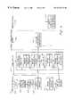
- the start state 300indicates that the SNMP system is operational.
- the SNMP system on the client computer 102includes a variety of modules including a MIB manager module 310 , the application module 110 , a windows module 320 and a network communications library 340 .
- the SNMP systemis Maestro Central from NetFrame Systems Inc.
- the various modulescommunication with each other to send network messages to the server computer 104 .
- the requestWhen initiating a synchronous request for data, the request includes an identifier 302 , a command 304 and one or more buffer(s) 306 .
- the identifier 302in one embodiment uniquely identifies different network components. For example, the identifier 302 will identify components such as fans, slots, adapters, processors, power supplies, canisters, interface cards, memory, etc.
- the command 304identifies the type of information to obtain about the identified component.
- the command 304can direct the server computer 104 to obtain data about a fan's speed, a fan's location, a temperature reading, a slot's power status, a slot's location, a slot's bus connection, an adapter's bus number, an adapter's vendor identification, whether an adapter supports hot plugability, a driver's name, a driver's version, a driver's type, a canister's location, a canister's name, a canister's serial number, a canister's power state, a power supply's status, a power supply's location, a CPU's clock frequency, a CPU's location or a voltage level at a particular point in a server, etc.
- the buffer 306is used to store the obtained data.
- the buffer 306can hold a wide variety of data structures including text, variables, tables, numerical values, flags, etc.
- requests by the application module 110can include a wide variety of data types and values.
- the requestsmay include other commands 304 which may or may not include data values.
- the MIB manager module 310accesses the unique identifier 302 of each component in the server computers 104 stored in the Management Information Base (“MIB”) data 114 .
- MIBManagement Information Base
- the application module 110desires information about a particular component, the application module 110 requests the identifier 302 of the desired component from the MIB manager module 310 .
- the MIB manager module 310accesses the MIB data 114 and returns the desired identifier 302 to the application module 110 .
- the windows module 320is used to pass messages among different modules.
- the window module 206is a standard Microsoft window for passing messages.
- the window module 206includes a notify flag 322 which notifies the SNMP module 112 that the requested data has been received. If multiple SNMP modules 112 exist, the window module 206 contains notify flags 322 which identify each SNMP module 112 .
- the network communications library 340 in one embodiment of the inventionis a standard WinSNMP Library.
- One such standard WinSNMP Libraryis distributed by ACE Communications.
- the network communications library 340facilitates communication over the network 106 by providing a plurality of function calls. Relevant function calls include a SendMsg function 342 , an SnmpSendMsg function 344 , a Receive function 346 and an SnmpReceiveMsg function 348 .
- the SendMsg function 342determines whether the network 106 is functional. If so, the SendMsg function 342 executes the SnmpSendMsg function 344 .
- the SnmpSendMsg function 344uses standard routines to initiate an SNMP asynchronous request.
- the Receive function 346determines whether data has been obtained. If so, the Receive function 346 executes the SnmpReceiveMsg function 348 .
- the SnmpReceiveMsg function 348executes standard routines to ensure that the obtained data is loaded in to the proper data buffer 306 .
- the synchronous transaction interface described hereinmay operate with libraries other then the WinSNMP Library.
- the WinSNMP Libraryis but one of many libraries available which provide a standardized collection of asynchronous computer software functions.
- the present synchronous transactions claimed hereinneed not obtain information from or operate in conjunction with such libraries.
- Other asynchronous software routinesmay be used.
- the SNMP module 112contains a number of methods (also called functions or routines) which support the synchronous interface 200 .
- routines for performing various functionsare commonly called methods.
- methodis used generally to refer software or hard components including functions, attributes, procedures, subroutines, segments of program code, drivers, firmware, microcode, circuitry, data, data structures, tables, arrays, variables, etc.
- the SNMP module 112includes the GET method 350 , the GETNEXT method 352 , the SET method 354 and the Task Loop method 356 .
- the functionality of the GET method 350 , the GETNEXT method 352 , the SET method 354 , and the Task Loop method 356could be collectively or independently implemented in different modules.
- the functionality of the GET method 350 , the GETNEXT method 352 , the SET method 354 or the Task Loop method 356could be incorporated into the application module 110 .
- the GET method 350is used to synchronously request the values of one or more data values.
- the GETNEXT method 352synchronously sequentially obtains one ore more organized values, such as values in a table while the SET method 354 sets a component variable to a desired value.
- the Task Loop module 356provides synchronous functionality. The Task Loop module 356 begins operation when the application module 110 invokes the GET method 350 , the GETNEXT method 352 or the SET method 354 .
- the Task Loop module 356includes a timer which monitors the time duration required to obtain a response from the server computer 104 . If a predetermined time duration is exceeded, the Task Loop module 356 responds that the requested data is unavailable. In one embodiment, the Task Loop module 356 also re-executes requests which have exceeded the desired time limit.
- FIG. 4illustrates a flow chart of one embodiment of the synchronous emulation process.
- FIG. 4is divided into four sections to more clearly delineate the operation and interaction of each module of the disclosed embodiment.
- FIG. 4is divided vertically from left to right to display the operation, of the application module 110 , the SNMP module 112 , the network communications library 340 , and the windows module 320 .
- FIG. 6shows an exemplary computer system 600 that implements one embodiment of the invention.
- the computer system 600includes at least one processor 610 that is configured to access at least one memory circuit 620 .
- the at least one processor 610may include multi-processor Pentium-based processors.
- the at least one memory circuit 620may comprise a conventional storage device, such as a hard disk, or a random access memory.
- the computer system 600further comprises a network communication interface 630 that asynchronously sends and receives data to and from a network, such as the network 106 .
- the memory circuit 620may store and the processor 610 may execute an application module and an accept request module.
- the application module 110is invoked and begins an execution thread. Furthermore, an SNMP module 112 is also created. If other application modules 110 are invoked, additional SNMP modules 112 are also created. Each SNMP module 112 is assigned its own handle.
- the process states of an exemplary application module 110are shown.
- the application module 110displays a number of data values about the operation of the server computers 104 on the screen of the client computer 102 . Proceeding to state 524 , the application module 110 creates a display window on the screen of the client computer 102 .
- the application module 110desires to display the operational status of a server fan.
- the application module 110creates a window for displaying the status of the server fan.
- application module 110initiates a request for data. To generate the request, the application module 110 creates a variable identifier list. The application module 110 obtains the desired identifiers 302 from the MIB manager module 310 and allocates the data buffer 306 for storing the desired data.
- the application module 110desires to obtain the status of a server fan, in state 428 , the application module 110 obtains the identifier 302 of the server fan from the MIB manager module 310 . While in state 428 , the application module 110 also allocates a data buffer 306 which will be used to store the data regarding the server fan.
- the application module 110initiates a synchronous information request.
- the application module 110initiates the synchronous information request by calling the GET method 350 , the GETNEXT method 352 or the SET method 354 in the SNMP module 112 . While only one GET, GETNEXT or SET method 350 , 352 or 354 is called at any given time, the methods 350 , 352 and 354 perform similar functions and are discussed collectively throughout this detailed description.
- the application module 110When calling either the GET, GETNEXT or SET method 350 , 352 or 354 , the application module 110 passes 1) the desired identifier(s) 302 , 2) the desired command 304 and 3) a pointer to the allocated data buffer 306 . For example, if the application module 110 wishes to obtain the status of a server fan, the application module 110 synchronously calls the GET method 350 and passes a fan identifier 302 , a fan status request command 304 and a pointer to a fan buffer 306 .
- the application module 110desires to obtain the status of a server fan and the status of a server power supply, the application module 110 synchronously calls the GET method 350 and passes a fan identifier 302 , a power supply identifier 302 , a fan status request command 304 , a power supply status command 304 , a pointer to a fan buffer 306 and a pointer to a power supply buffer 306 . The application module 110 then suspends execution until the application module 110 receives a response containing all of the requested data.
- the SNMP module 112executes the synchronous request from the applications module 110 . That is, the SNMP module 112 executes the GET, GETNEXT or SET method 350 , 352 or 354 . In the server fan example mentioned above, the SNMP module 112 executes the GET method 350 .
- the GET, GETNEXT or SET method 350 , 352 or 354initiates an asynchronous request.
- the methods 350 , 352 or 354execute the SendMsg function 342 in the network communications library 340 .
- the methods 350 , 352 or 354pass the handle of the SNMP module 112 , the identifier 302 , the command 304 and the pointer to the data buffer 306 .
- the SendMsg function 342then queries the network 106 and identifies whether the network 106 is operational.
- the GET method 350executes the SendMsg function 342 .
- the GET method 350passes the handle of the SNMP module 112 , the identifier 302 of the fan, fan status command 304 and the fan buffer 306 .
- the GET method 350passes the handle of the SNMP module 112 , the corresponding identifiers 302 , commands 304 and buffers 306 to the SendMsg function 342 .
- the SendMsg function 342executes the SnmpSendMsg function 344 existing in the network communications library 340 .
- the SendMsg function 342executes the SnmpSendMsg function 344 , it passes the identifier 302 , the command 304 and the pointer to the data buffer 306 .
- the SnmpSendMsg function 344then performs an asynchronous transaction on the network 106 . If multiple data values are requested the SnmpSendMsg function 344 generates an asynchronous request for multiple data values.
- the SendMsg function 342executes the SnmpSendMsg function 344 and passes to the SnmpSendMsg function 344 , the handle of the SNMP module 112 , the fan identifier 302 , the fan status command 304 and the pointer to the fan buffer 306 .
- the Task Loop module 356monitors the time needed to obtain a response from the server computer 104 .
- the Task Loop module 356is further described in the section entitled “The Operation Of the Task Loop Module.” In the server fan example, the Task Loop module 356 monitors the time needed to obtain the requested fan status data.
- the SnmpSendMsg function 344uses the handle of the SNMP module 112 to set the notify flag 322 in the windows module 320 indicating that the requested data for that SNMP module 112 has been obtained.
- the notify flag 322is set, the windows module 320 , in turn, notifies the identified SNMP module 112 that the data has been obtained.
- windows module 320identifies the proper SNMP module 112 which initiated a particular request.
- the SnmpSendMsg function 344uses the handle of the SNMP module 112 to set the proper notify flag 322 in the windows module 320 .
- the windows module 320notifies the identified SNMP module 112 that the fan data has been obtained.
- the windows module 320can provide notification to multiple SNMP modules 112 .
- the SnmpSendMsg function 344sets a task complete indicator.
- the Task Loop module 356may monitor the task complete indicator to determine when to execute the SnmpReceiveMsg function 348 to thereby retrieve the data from the network communications library 340 .
- the SNMP module 112obtains the data using the SnmpReceiveMsg function 348 .
- the SnmpReceiveMsg function 348transfers the data to the data buffer 306 .
- the SnmpReceiveMsg function 348then transfers the pointer to the data buffer 306 back to the SNMP module 112 .
- the SnmpReceiveMsg function 348transfers the requested fan information to the fan buffer 306 .
- a pointer to the fan buffer 306is then transferred back to the SNMP module 112 .
- the SNMP module 112then forwards the data buffer 306 back to the application module 110 .
- the GET method 350returns the pointer to the fan buffer 306 back to the application module 110 .
- the application module 110can now continue execution. In this example, the application module 110 proceeds to state 468 and displays the data in the fan buffer 306 in a window on the client computer 102 .
- FIG. 5illustrates a flow chart of one embodiment of the Task Loop module 356 existing within the SNMP module 112 .
- the Task Loop module 356emulates a feature of a synchronous network system by ensuring that a request is completed within a maximum time duration. If the request is not complete within the maximum time duration, the Task Loop module 356 notifies the application module 110 that the desired data is not available.
- the Task Loop module 356proceeds to state 502 .
- the Task Loop module 356monitors the time duration needed to obtain a response to the asynchronous transaction.
- the Task Loop module 356monitors the time duration with a timer. The timer is designed to count to a maximum time duration. After reaching the maximum duration, the Task Loop module 356 is said to have “timed out.”
- the Task Loop module 356monitors the duration needed to obtain the data about the fan. If the time to obtain the fan data exceeds a set time limit, the Task Loop module 356 notifies the application module 110 that the fan data is not available.
- the SNMP module 112proceeds to state 506 .
- the GET, the GETNEXT or the SET method 350 , 352 , or 354call the Receive function 346 in the network communications library 340 .
- the Receive function 346passes the handle of their SNMP module 112 to the network communications library 340 .
- the Receive function 346passes the handle to the SNMP module 112 to the SnmpReceiveMsg function 348 .
- the received dataexists in the data buffer 306 and the SnmpReceiveMsg function 348 returns the data buffer 306 back to the GET, GETNEXT or SET method 350 , 352 or 354 .
- the GET method 350calls the Receive function 346 and passes the handle of its SNMP module 112 .
- the Receive function 346passes the handle of the SNMP module 112 to the SnmpReceiveMsg function 348 .
- the SnmpReceiveMsg function 348then uses the handle to passes a pointer to the fan data buffer 306 back to the GET method 350 .
- the GET, GETNEXT or SET method 350 , 352 or 354have now obtained the requested data. Proceeding to state 460 , the GET, GETNEXT or SET method 350 , 352 or 354 return the pointer to the filled data buffer 306 to the application module 110 .
- the GET method 350passes the pointer back to the application module 110 .
- the application module 110can then resume operation and access the fan data in the fan data buffer 306 .
- One aspect of emulating a synchronous transactionincludes monitoring the duration required to process an asynchronous request.
- an asynchronous systemat the time an asynchronous request is initiated, it is not known how long it will take to obtain a response. In many synchronous systems, however, long delays create problems.
- the applicationsuspends operation until the application obtains the desired response. If a response is not obtained in a timely manner, the application can appear to “hang.” That is, the application may appear to have ceased functioning when the application suspends operation for an excessive amount of time.
- One embodiment of the inventionovercomes such “hang” problems by monitoring the time associated with obtaining an asynchronous response.
- this embodimenthas not received a response within a predefined time limit, this embodiment of the invention provides a response back to the client application that the requested data is unavailable. Providing a predefined time limit allows the application program to resume operation before it appears to “hang.”
- the application module 110initiates a synchronous request for data. After initiating the request, the application module 110 suspends operation.
- the synchronous interface 200 of the SNMP module 112receives the synchronous request for data and initiates an asynchronous request on the network 106 .
- the SNMP module 112monitors the time duration of the pending synchronous request.
- the SNMP module 112If a response is not received within a predetermined time duration, the SNMP module 112 notifies the suspended application that the response has not been received. This allows the application module 110 to resume operations. In such a situation, the application module 110 can communicate to the user that the desired data is not available.
- the time duration in state 502is set by a user.
- the timer periodmay be set from 1 milliseconds to 20 seconds.
- the timeris set from 50 milliseconds to 10 seconds.
- the timeris set at 5 seconds.
- the timer operationis a software routine which will monitor the time until an event occurs.
- the timer operationcan be configured to periodically or continuously monitor a flag or event.
- the timer in state 502awaits notification from the notification window in state 504 .
- the timercontinuously monitors the notification flag in the windows module 320 .
- the Task Loop module 356proceeds to state 520 .
- the SNMP module 112also can re-executing failed requests. As explained above, in an asynchronous system some requests may take an excessive time to process. In addition, networking components may cease functioning and consequently fail to process certain requests.
- one embodiment of the SNMP module 112re-executes failed or delayed requests. Furthermore, the number of repeated attempts can be selectively configured.
- the SNMP module 112is configured to re-execute failed requests two times.
- the application module 110When the application module 110 generates a synchronous request, the SNMP module 112 will in turn, initiate an asynchronous request. If a response is not received within a desired time limit, the SNMP module 112 will execute another synchronous request. If, after the second time, a response has not been received, the SNMP module 112 will notify the application module 110 that the data is not available.
- the Task Loop module 356can attempt to resend an asynchronous request for data which has not been obtained within the maximum time duration. Thus, if data is not obtained within a desired time limit, the Task Loop module 356 can send another request for the data.
- the Task Loop module 356counts the number of attempts to obtain the data (also called retry queries).
- the maximum retries valuemay be set by the network administrator or computer operator. In one embodiment, it is contemplated that the maximum number of retries may be set from 0 to 100. In another embodiment, the maximum number of retries may be set from 0 to 10. In yet another embodiment, the maximum number of retries is set at 2.
- the Tasks Loop module 356proceeds again to state 448 and re-executes the SendMsg function 342 and SnmpSendMsg function 344 thereby resubmitting another request to the server computer 104 .
- the SendMsg function 342 and SnmpSendMsg function 344cancel the previous pending request when initiating a new request.
- the Task Loop module 356re-initiates another request.
- the Task Loop module 356proceeds to state 522 .
- the GET, GETNEXT or SET method 350 , 352 , or 354send an “information not available” message to the application module 110 . This allows the application module 110 to resume operation within a predetermined time limit when data is unavailable.
- the GET method 350returns an “information not available” message to the application module 110 .
- the application module 110can then display to the user that the requested fan data is unavailable.
- the unique synchronous interfaceallows the application module 110 to execute synchronous transactions in an asynchronous environment. Because the invention supports synchronous transactions, the complexity of the application module 110 is greatly reduced. The application module 110 does not need to monitor the status of multiple pending asynchronous transactions. Furthermore, the application module 110 does not need to match each request with its corresponding response.
- one embodiment of the inventionprovides synchronous support by providing a timer which monitors when an asynchronous transaction has exceeded a time limit.
- a timerallows the synchronous interface to provide a response to a synchronous request within a set time limit.
- the application module 110may suspend execution. If the asynchronous transaction exceeds a certain amount of time, the application module 110 can appear to freeze or hang.
- the timerensures that a long delay in processing a transaction will not suspend the application module 110 beyond a desired time duration.
- one embodiment of the inventionprovides a retry query feature.
- the retry query featureallows a user to define the number of times to re-execute a data request. Thus, if a data request is not obtained within a desired time duration, the data request can be resent as many times as desired. If the data has not been obtained after repeated attempts, the application module 110 which initiated the data request can be notified that the data is unavailable.
- Yet another advantage of one embodiment of the inventionis that the application module 110 can rely on the orderly processing of data requests.
- data requestsare processed individually and thus the order of receiving the responses is not guaranteed.
- the synchronous transactions in one embodiment of the inventionensures that the responses to the data requests are obtained in an orderly manner.
Landscapes
- Engineering & Computer Science (AREA)
- Computer Networks & Wireless Communication (AREA)
- Signal Processing (AREA)
- General Engineering & Computer Science (AREA)
- Theoretical Computer Science (AREA)
- Human Computer Interaction (AREA)
- Computer Hardware Design (AREA)
- Physics & Mathematics (AREA)
- General Physics & Mathematics (AREA)
- Computer And Data Communications (AREA)
Abstract
Description
| Title | Application No. | ||
| “System Architecture for Remote Access | 08/942,160 | ||
| and Control of Environmental | |||
| Management” | |||
| “Method of Remote Access and Control of | 08/942,215 | ||
| Environmental Management” | |||
| “System for Independent Powering of | 08/942,410 | ||
| Diagnostic Processes on a Computer | |||
| System” | |||
| “Method of Independent Powering of | 08/942,320 | ||
| Diagnostic Processes on a Computer | |||
| System” | |||
| “Diagnostic and Managing Distributed | 08/942,402 | ||
| Processor System” | |||
| “Method for Managing a Distributed | 08/942,448 | ||
| Processor System” | |||
| “System for Mapping Environmental | 08/942,222 | ||
| Resources to Memory for Program Access” | |||
| “Method for Mapping Environmental | 08/942,214 | ||
| Resources to Memory for Program Access” | |||
| “Hot Add of Devices Software | 08/942,309 | ||
| Architecture” | |||
| “Method for The Hot Add of Devices” | 08/942,306 | ||
| “Hot Swap of Devices Software | 08/942,311 | ||
| Architecture” | |||
| “Method for The Hot Swap of Devices” | 08/942,457 | ||
| “Method for the Hot Add of a Network | 08/943,072 | ||
| Adapter on a System Including a | |||
| Dynamically Loaded Adapter Driver” | |||
| “Method for the Hot Add of a Mass | 08/942,069 | ||
| Storage Adapter on a System Including a | |||
| Statically Loaded Adapter Driver” | |||
| “Method for the Hot Add of a Network | 08/942,465 | ||
| Adapter on a System Including a Statically | |||
| Loaded Adapter Driver” | |||
| “Method for the Hot Add of a Mass | 08/962,963 | ||
| Storage Adapter on a System Including a | |||
| Dynamically Loaded Adapter Driver” | |||
| “Method for the Hot Swap of a Network | 08/943,078 | ||
| Adapter on a System Including a | |||
| Dynamically Loaded Adapter Driver” | |||
| “Method for the Hot Swap of a Mass | 08/942,336 | ||
| Storage Adapter on a System Including a | |||
| Statically Loaded Adapter Driver” | |||
| “Method for the Hot Swap of a Network | 08/942,459 | ||
| Adapter on a System Including a Statically | |||
| Loaded Adapter Driver” | |||
| “Method for the Hot Swap of a Mass | 08/942,458 | ||
| Storage Adapter on a System Including a | |||
| Dynamically Loaded Adapter Driver” | |||
| “Method of Performing an Extensive | 08/942,463 | ||
| Diagnostic Test in Conjunction with a | |||
| BIOS Test Routine” | |||
| “Apparatus for Performing an Extensive | 08/942,163 | ||
| Diagnostic Test in Conjunction with a | |||
| BIOS Test Routine” | |||
| “Configuration Management Method for | 08/941,268 | ||
| Hot Adding and Hot Replacing Devices” | |||
| “Configuration Management System for | 08/942,408 | ||
| Hot Adding and Hot Replacing Devices” | |||
| “Apparatus for Interfacing Buses” | 08/942,382 | ||
| “Method for Interfacing Buses” | 08/942,413 | ||
| “Computer Fan Speed Control Device” | 08/942,447 | ||
| “Computer Fan Speed Control Method” | 08/942,216 | ||
| “System for Powering Up and Powering | 08/943,076 | ||
| Down a Server” | |||
| “Method of Powering Up and Powering | 08/943,077 | ||
| Down a Server” | |||
| “System for Resetting a Server” | 08/942,333 | ||
| “Method of Resetting a Server” | 08/942,405 | ||
| “System for Displaying Flight Recorder” | 08/942,070 | ||
| “Method of Displaying Flight Recorder” | 08/942,068 | ||
| “Synchronous Communication Emulation” | 08/942,004 | ||
| “Software System Facilitating the | 08/942,317 | ||
| Replacement or Insertion of Devices in a | |||
| Computer System” | |||
| “Method for Facilitating the Replacement | 08/942,316 | ||
| or Insertion of Devices in a Computer | |||
| System” | |||
| “System Management Graphical User | 08/943,357 | ||
| Interface” | |||
| “Display of System Information” | 08/942,195 | ||
| “Data Management System Supporting Hot | 08/942,129 | ||
| Plug Operations on a Computer” | |||
| “Data Management Method Supporting | 08/942,124 | ||
| Hot Plug Operations on a Computer” | |||
| “Alert Configurator and Manager” | 08/942,005 | ||
| “Managing Computer System Alerts” | 08/943,356 | ||
| “Computer Fan Speed Control System” | 08/940,301 | ||
| “Computer Fan Speed Control System | 08/941,267 | ||
| Method” | |||
| “Black Box Recorder for Information | 08/942,381 | ||
| System Events” | |||
| “Method of Recording Information System | 08/942,164 | ||
| Events” | |||
| “Method for Automatically Reporting a | 08/942,168 | ||
| System Failure in a Server” | |||
| “System for Automatically Reporting a | 08/942,384 | ||
| System Failure in a Server” | |||
| “Expansion of PCI Bus Loading Capacity” | 08/942,404 | ||
| “Method for Expanding PCI Bus Loading | 08/942,223 | ||
| Capacity” | |||
| “System for Displaying System Status” | 08/942,347 | ||
| “Method of Displaying System Status” | 08/942,071 | ||
| “Fault Tolerant Computer System” | 08/942,194 | ||
| “Method for Hot Swapping of Network | 08/943,044 | ||
| Components” | |||
| “A Method for Communicating a Software | 08/942,221 | ||
| Generated Pulse Waveform Between Two | |||
| Servers in a Network” | |||
| “A System for Communicating a Software | 08/942,409 | ||
| Generated Pulse Waveform Between Two | |||
| Servers in a Network” | |||
| “Method for Clustering Software | 08/942,318 | ||
| Applications” | |||
| “System for Clustering Software | 08/942,411 | ||
| Applications” | |||
| “Method for Automatically Configuring a | 08/942,319 | ||
| Server after Hot Add of a Device” | |||
| “System for Automatically Configuring a | 08/942,331 | ||
| Server after Hot Add of a Device” | |||
| “Method of Automatically Configuring and | 08/942,412 | ||
| Formatting a Computer System and | |||
| Installing Software” | |||
| “System for Automatically Configuring | 08/941,955 | ||
| and Formatting a Computer System and | |||
| Installing Software” | |||
| “Determining Slot Numbers in a | 08/942,462 | ||
| Computer” | |||
| “System for Detecting Errors in a Network” | 08/942,169 | ||
| “Method of Detecting Errors in a Network” | 08/940,302 | ||
| “System for Detecting Network Errors” | 08/942,407 | ||
| “Method of Detecting Network Errors” | 08/942,573 | ||
Claims (24)
Priority Applications (1)
| Application Number | Priority Date | Filing Date | Title |
|---|---|---|---|
| US08/943,355US6219711B1 (en) | 1997-05-13 | 1997-10-01 | Synchronous communication interface |
Applications Claiming Priority (2)
| Application Number | Priority Date | Filing Date | Title |
|---|---|---|---|
| US4631097P | 1997-05-13 | 1997-05-13 | |
| US08/943,355US6219711B1 (en) | 1997-05-13 | 1997-10-01 | Synchronous communication interface |
Publications (1)
| Publication Number | Publication Date |
|---|---|
| US6219711B1true US6219711B1 (en) | 2001-04-17 |
Family
ID=26723772
Family Applications (1)
| Application Number | Title | Priority Date | Filing Date |
|---|---|---|---|
| US08/943,355Expired - LifetimeUS6219711B1 (en) | 1997-05-13 | 1997-10-01 | Synchronous communication interface |
Country Status (1)
| Country | Link |
|---|---|
| US (1) | US6219711B1 (en) |
Cited By (51)
| Publication number | Priority date | Publication date | Assignee | Title |
|---|---|---|---|---|
| US6389470B1 (en)* | 1998-06-17 | 2002-05-14 | Tellabs Research Limited | Telecommunication controller messaging system using middlewares to decouple applications from system resources |
| US20020103866A1 (en)* | 2000-11-30 | 2002-08-01 | Chi Yueh-Shian T. | Dynamic subject information generation in message services of distributed object systems |
| US20020128735A1 (en)* | 2001-03-08 | 2002-09-12 | Hawkins Parris C.M. | Dynamic and extensible task guide |
| US20020138321A1 (en)* | 2001-03-20 | 2002-09-26 | Applied Materials, Inc. | Fault tolerant and automated computer software workflow |
| US20020156548A1 (en)* | 1999-07-29 | 2002-10-24 | Applied Materials, Inc. | Computer integrated manufacturing techniques |
| US20020161698A1 (en)* | 2000-10-04 | 2002-10-31 | Wical Kelly J. | Caching system using timing queues based on last access times |
| US20020166000A1 (en)* | 2001-03-22 | 2002-11-07 | Markku Rossi | Method for inverting program control flow |
| US20020193902A1 (en)* | 2001-06-19 | 2002-12-19 | Applied Materials, Inc. | Integrating tool, module, and fab level control |
| US20020193899A1 (en)* | 2001-06-19 | 2002-12-19 | Applied Materials, Inc. | Dynamic metrology schemes and sampling schemes for advanced process control in semiconductor processing |
| US20020199082A1 (en)* | 2001-06-19 | 2002-12-26 | Applied Materials, Inc. | Method, system and medium for process control for the matching of tools, chambers and/or other semiconductor-related entities |
| US20020197745A1 (en)* | 2001-06-19 | 2002-12-26 | Shanmugasundram Arulkumar P. | Feedback control of a chemical mechanical polishing device providing manipulation of removal rate profiles |
| US20030005105A1 (en)* | 2001-05-30 | 2003-01-02 | Anne Robb | Method and apparatus for a common management software systems |
| US20030014145A1 (en)* | 2001-07-16 | 2003-01-16 | Applied Materials, Inc. | Integration of fault detection with run-to-run control |
| US20030027424A1 (en)* | 2001-06-19 | 2003-02-06 | Paik Young Joseph | Feedforward and feedback control for conditioning of chemical mechanical polishing pad |
| US20030049376A1 (en)* | 2001-06-19 | 2003-03-13 | Applied Materials, Inc. | Feedback control of sub-atmospheric chemical vapor deposition processes |
| US20030049390A1 (en)* | 2001-06-19 | 2003-03-13 | Applied Materials, Inc. | Feedback control of plasma-enhanced chemical vapor deposition processes |
| US20030061443A1 (en)* | 2001-09-26 | 2003-03-27 | Michael Frank | System for handling memory requests and method thereof |
| US20030159078A1 (en)* | 2002-02-12 | 2003-08-21 | Fulcrum Microsystems Inc. | Techniques for facilitating conversion between asynchronous and synchronous domains |
| US6625637B1 (en)* | 1999-12-09 | 2003-09-23 | Koninklijke Philips Electronics N.V. | Method and apparatus for synthesizing communication support based on communication types of application |
| US20030180972A1 (en)* | 2002-03-19 | 2003-09-25 | Amir Al-Bayati | Method, system and medium for controlling semiconductor wafer processes using critical dimension measurements |
| US20030199112A1 (en)* | 2002-03-22 | 2003-10-23 | Applied Materials, Inc. | Copper wiring module control |
| US6708074B1 (en)* | 2000-08-11 | 2004-03-16 | Applied Materials, Inc. | Generic interface builder |
| US20040063224A1 (en)* | 2002-09-18 | 2004-04-01 | Applied Materials, Inc. | Feedback control of a chemical mechanical polishing process for multi-layered films |
| US20040083021A1 (en)* | 1999-12-22 | 2004-04-29 | Applied Materials, Inc. | Multi-tool control system, method and medium |
| US20040148049A1 (en)* | 2003-01-21 | 2004-07-29 | Applied Materials, Inc. | Automated design and execution of experiments with integrated model creation for semiconductor manufacturing tools |
| US20040248409A1 (en)* | 2003-06-03 | 2004-12-09 | Applied Materials, Inc. | Selective metal encapsulation schemes |
| US20050032459A1 (en)* | 2003-08-04 | 2005-02-10 | Applied Materials, Inc. | Technique for process-qualifying a semiconductor manufacturing tool using metrology data |
| US20050171626A1 (en)* | 2004-01-29 | 2005-08-04 | Applied Materials, Inc. | System, method, and medium for monitoring performance of an advanced process control system |
| US20050208879A1 (en)* | 2001-06-19 | 2005-09-22 | Applied Materials | Control of chemical mechanical polishing pad conditioner directional velocity to improve pad life |
| US6961626B1 (en) | 2004-05-28 | 2005-11-01 | Applied Materials, Inc | Dynamic offset and feedback threshold |
| US6971105B1 (en)* | 1999-07-29 | 2005-11-29 | Rehle Visual Communications Llc | Method, apparatus, and computer program product for deferred completion of multi-step user transaction applications |
| US20050278051A1 (en)* | 2004-05-28 | 2005-12-15 | Applied Materials, Inc. | Process control by distinguishing a white noise component of a process variance |
| US6984198B2 (en) | 2001-08-14 | 2006-01-10 | Applied Materials, Inc. | Experiment management system, method and medium |
| US6999836B2 (en) | 2002-08-01 | 2006-02-14 | Applied Materials, Inc. | Method, system, and medium for handling misrepresentative metrology data within an advanced process control system |
| US20060069942A1 (en)* | 2004-09-04 | 2006-03-30 | Brasilerio Francisco V | Data processing system and method |
| US20060225082A1 (en)* | 2005-03-29 | 2006-10-05 | Microsoft Corporation | Synchronous RIL proxy |
| US20060224431A1 (en)* | 2003-08-27 | 2006-10-05 | Hans-Ulrich Von Helmolt | Data processing method, system and computer program |
| US7272459B2 (en) | 2002-11-15 | 2007-09-18 | Applied Materials, Inc. | Method, system and medium for controlling manufacture process having multivariate input parameters |
| US20090006821A1 (en)* | 2007-06-29 | 2009-01-01 | Kabushiki Kaisha Toshiba | Apparatus, method, and computer program product for processing information by controlling arithmetic mode |
| US7509642B1 (en)* | 2003-09-17 | 2009-03-24 | Sprint Communications Company L.P. | Method and system for automatically providing network-transaction-status updates |
| US20090293073A1 (en)* | 2008-05-20 | 2009-11-26 | Microsoft Corporation | Automating asynchronous programming in single threaded systems |
| US20100082678A1 (en)* | 2008-09-30 | 2010-04-01 | Rockwell Automation Technologies, Inc. | Aggregation server with industrial automation control and information visualization placeshifting |
| US20110246640A1 (en)* | 2010-04-06 | 2011-10-06 | Debashis Saha | Method and system for synchronous and asynchronous monitoring |
| US8091125B1 (en)* | 2002-01-14 | 2012-01-03 | Fs Networks, Inc. | Method and system for performing asynchronous cryptographic operations |
| US20140108492A1 (en)* | 2012-10-15 | 2014-04-17 | International Business Machines Corporation | Request-response operation for asynchronous messaging |
| US20140250436A1 (en)* | 2011-05-27 | 2014-09-04 | Transoft (Shanghai), Inc. | Transaction-based service control system and control method |
| US9729677B2 (en)* | 2015-04-28 | 2017-08-08 | David Wei Ge | Method of adding client server automation to computer languages for cloud computing |
| US10303513B2 (en)* | 2013-03-13 | 2019-05-28 | Microsoft Technology Licensing, Llc | Durable program execution |
| US10467892B2 (en) | 2016-11-17 | 2019-11-05 | Cisco Technology, Inc. | Method and apparatus for exchanging information through a tachometer signal |
| US20220321346A1 (en)* | 2021-03-31 | 2022-10-06 | Microsoft Technology Licensing, Llc | Token management for asynchronous request-reply |
| US12086450B1 (en)* | 2018-09-26 | 2024-09-10 | Amazon Technologies, Inc. | Synchronous get copy for asynchronous storage |
Citations (40)
| Publication number | Priority date | Publication date | Assignee | Title |
|---|---|---|---|---|
| US4999787A (en) | 1988-07-15 | 1991-03-12 | Bull Hn Information Systems Inc. | Hot extraction and insertion of logic boards in an on-line communication system |
| US5210855A (en) | 1989-06-09 | 1993-05-11 | International Business Machines Corporation | System for computer peripheral bus for allowing hot extraction on insertion without disrupting adjacent devices |
| US5274680A (en)* | 1990-11-23 | 1993-12-28 | Thomson-Csf | Device for the transmission of synchronous information by an asynchronous network, notably an ATM network |
| US5386567A (en) | 1992-01-20 | 1995-01-31 | International Business Machines Corp. | Hot removable and insertion of attachments on fully initialized computer systems |
| US5471617A (en) | 1991-06-24 | 1995-11-28 | Compaq Computer Corporation | Computer management system and associated management information base |
| US5517646A (en) | 1994-04-25 | 1996-05-14 | Compaq Computer Corp. | Expansion device configuration system having two configuration modes which uses automatic expansion configuration sequence during first mode and configures the device individually during second mode |
| US5546595A (en) | 1993-12-21 | 1996-08-13 | Taligent, Inc. | Object-oriented system using objects representing hardware devices, physical connectors and connections between the physical connectors for configuring a computer |
| US5555510A (en) | 1994-08-02 | 1996-09-10 | Intel Corporation | Automatic computer card insertion and removal algorithm |
| US5561769A (en)* | 1994-05-10 | 1996-10-01 | Lucent Technologies Inc. | Method and apparatus for executing a distributed algorithm or service on a simple network management protocol based computer network |
| US5579491A (en) | 1994-07-07 | 1996-11-26 | Dell U.S.A., L.P. | Local proactive hot swap request/acknowledge system |
| US5581712A (en) | 1994-11-17 | 1996-12-03 | Intel Corporation | Method and apparatus for managing live insertion of CPU and I/O boards into a computer system |
| US5666362A (en)* | 1995-07-25 | 1997-09-09 | 3Com Corporation | Method and apparatus for asynchronous PPP and synchronous PPP conversion |
| US5671441A (en) | 1994-11-29 | 1997-09-23 | International Business Machines Corporation | Method and apparatus for automatic generation of I/O configuration descriptions |
| US5678006A (en)* | 1995-04-27 | 1997-10-14 | Cisco Systems, Inc. | Network switch having network management agent functions distributed among multiple trunk and service modules |
| US5678042A (en) | 1993-11-15 | 1997-10-14 | Seagate Technology, Inc. | Network management system having historical virtual catalog snapshots for overview of historical changes to files distributively stored across network domain |
| US5696486A (en) | 1995-03-29 | 1997-12-09 | Cabletron Systems, Inc. | Method and apparatus for policy-based alarm notification in a distributed network management environment |
| US5710908A (en)* | 1995-06-27 | 1998-01-20 | Canon Kabushiki Kaisha | Adaptive network protocol independent interface |
| US5748098A (en) | 1993-02-23 | 1998-05-05 | British Telecommunications Public Limited Company | Event correlation |
| US5751933A (en) | 1990-09-17 | 1998-05-12 | Dev; Roger H. | System for determining the status of an entity in a computer network |
| US5758103A (en) | 1995-08-31 | 1998-05-26 | Samsung Electronics Co., Ltd. | Circuit for replacing a peripheral device of a computer system and method therefor |
| US5768541A (en) | 1995-06-15 | 1998-06-16 | Dell U.S.A., L.P. | System for hot-plugging peripheral device to computer bus and disconnecting peripheral device upon detecting predetermined sequence of keystrokes inputted by user through keyboard |
| US5781798A (en) | 1993-12-30 | 1998-07-14 | International Business Machines Corporation | Method and apparatus for providing hot swapping capability in a computer system with static peripheral driver software |
| US5784576A (en) | 1996-10-31 | 1998-07-21 | International Business Machines Corp. | Method and apparatus for adding and removing components of a data processing system without powering down |
| US5787246A (en) | 1994-05-27 | 1998-07-28 | Microsoft Corporation | System for configuring devices for a computer system |
| US5796633A (en) | 1996-07-12 | 1998-08-18 | Electronic Data Systems Corporation | Method and system for performance monitoring in computer networks |
| US5799016A (en)* | 1996-01-11 | 1998-08-25 | U S West, Inc. | Network addressing scheme encoding communication channel information |
| US5802146A (en) | 1995-11-22 | 1998-09-01 | Bell Atlantic Network Services, Inc. | Maintenance operations console for an advanced intelligent network |
| US5815652A (en) | 1995-05-31 | 1998-09-29 | Hitachi, Ltd. | Computer management system |
| US5838319A (en) | 1994-12-13 | 1998-11-17 | Microsoft Corporation | System provided child window control for displaying items in a hierarchical fashion |
| US5862333A (en) | 1994-05-05 | 1999-01-19 | Graf; Lars Oliver | System for managing group of computers by displaying only relevant and non-redundant alert message of the highest severity and controlling processes based on system resources |
| US5892912A (en)* | 1995-11-02 | 1999-04-06 | The Furukawa Electric Co., Ltd. | Method of managing virtual networks using a virtual network identifier |
| US5901304A (en) | 1997-03-13 | 1999-05-04 | International Business Machines Corporation | Emulating quasi-synchronous DRAM with asynchronous DRAM |
| US5907610A (en)* | 1996-01-11 | 1999-05-25 | U S West, Inc. | Networked telephony central offices |
| US5910954A (en)* | 1994-08-01 | 1999-06-08 | 3Com Corporation | Network switch |
| US5918004A (en) | 1995-06-02 | 1999-06-29 | Rational Software Corporation | Remote monitoring of computer programs |
| US5919258A (en) | 1996-02-08 | 1999-07-06 | Hitachi, Ltd. | Security system and method for computers connected to network |
| US5944782A (en) | 1996-10-16 | 1999-08-31 | Veritas Software Corporation | Event management system for distributed computing environment |
| US5961596A (en) | 1996-02-14 | 1999-10-05 | Hitachi, Ltd. | Method of monitoring a computer system, featuring performance data distribution to plural monitoring processes |
| US6000045A (en) | 1996-05-28 | 1999-12-07 | Cabletron Systems, Inc. | Method and apparatus for inter-domain alarm correlation |
| US6023507A (en) | 1997-03-17 | 2000-02-08 | Sun Microsystems, Inc. | Automatic remote computer monitoring system |
- 1997
- 1997-10-01USUS08/943,355patent/US6219711B1/ennot_activeExpired - Lifetime
Patent Citations (40)
| Publication number | Priority date | Publication date | Assignee | Title |
|---|---|---|---|---|
| US4999787A (en) | 1988-07-15 | 1991-03-12 | Bull Hn Information Systems Inc. | Hot extraction and insertion of logic boards in an on-line communication system |
| US5210855A (en) | 1989-06-09 | 1993-05-11 | International Business Machines Corporation | System for computer peripheral bus for allowing hot extraction on insertion without disrupting adjacent devices |
| US5751933A (en) | 1990-09-17 | 1998-05-12 | Dev; Roger H. | System for determining the status of an entity in a computer network |
| US5274680A (en)* | 1990-11-23 | 1993-12-28 | Thomson-Csf | Device for the transmission of synchronous information by an asynchronous network, notably an ATM network |
| US5471617A (en) | 1991-06-24 | 1995-11-28 | Compaq Computer Corporation | Computer management system and associated management information base |
| US5386567A (en) | 1992-01-20 | 1995-01-31 | International Business Machines Corp. | Hot removable and insertion of attachments on fully initialized computer systems |
| US5748098A (en) | 1993-02-23 | 1998-05-05 | British Telecommunications Public Limited Company | Event correlation |
| US5678042A (en) | 1993-11-15 | 1997-10-14 | Seagate Technology, Inc. | Network management system having historical virtual catalog snapshots for overview of historical changes to files distributively stored across network domain |
| US5546595A (en) | 1993-12-21 | 1996-08-13 | Taligent, Inc. | Object-oriented system using objects representing hardware devices, physical connectors and connections between the physical connectors for configuring a computer |
| US5781798A (en) | 1993-12-30 | 1998-07-14 | International Business Machines Corporation | Method and apparatus for providing hot swapping capability in a computer system with static peripheral driver software |
| US5517646A (en) | 1994-04-25 | 1996-05-14 | Compaq Computer Corp. | Expansion device configuration system having two configuration modes which uses automatic expansion configuration sequence during first mode and configures the device individually during second mode |
| US5862333A (en) | 1994-05-05 | 1999-01-19 | Graf; Lars Oliver | System for managing group of computers by displaying only relevant and non-redundant alert message of the highest severity and controlling processes based on system resources |
| US5561769A (en)* | 1994-05-10 | 1996-10-01 | Lucent Technologies Inc. | Method and apparatus for executing a distributed algorithm or service on a simple network management protocol based computer network |
| US5787246A (en) | 1994-05-27 | 1998-07-28 | Microsoft Corporation | System for configuring devices for a computer system |
| US5579491A (en) | 1994-07-07 | 1996-11-26 | Dell U.S.A., L.P. | Local proactive hot swap request/acknowledge system |
| US5910954A (en)* | 1994-08-01 | 1999-06-08 | 3Com Corporation | Network switch |
| US5555510A (en) | 1994-08-02 | 1996-09-10 | Intel Corporation | Automatic computer card insertion and removal algorithm |
| US5581712A (en) | 1994-11-17 | 1996-12-03 | Intel Corporation | Method and apparatus for managing live insertion of CPU and I/O boards into a computer system |
| US5671441A (en) | 1994-11-29 | 1997-09-23 | International Business Machines Corporation | Method and apparatus for automatic generation of I/O configuration descriptions |
| US5838319A (en) | 1994-12-13 | 1998-11-17 | Microsoft Corporation | System provided child window control for displaying items in a hierarchical fashion |
| US5696486A (en) | 1995-03-29 | 1997-12-09 | Cabletron Systems, Inc. | Method and apparatus for policy-based alarm notification in a distributed network management environment |
| US5678006A (en)* | 1995-04-27 | 1997-10-14 | Cisco Systems, Inc. | Network switch having network management agent functions distributed among multiple trunk and service modules |
| US5815652A (en) | 1995-05-31 | 1998-09-29 | Hitachi, Ltd. | Computer management system |
| US5918004A (en) | 1995-06-02 | 1999-06-29 | Rational Software Corporation | Remote monitoring of computer programs |
| US5768541A (en) | 1995-06-15 | 1998-06-16 | Dell U.S.A., L.P. | System for hot-plugging peripheral device to computer bus and disconnecting peripheral device upon detecting predetermined sequence of keystrokes inputted by user through keyboard |
| US5710908A (en)* | 1995-06-27 | 1998-01-20 | Canon Kabushiki Kaisha | Adaptive network protocol independent interface |
| US5666362A (en)* | 1995-07-25 | 1997-09-09 | 3Com Corporation | Method and apparatus for asynchronous PPP and synchronous PPP conversion |
| US5758103A (en) | 1995-08-31 | 1998-05-26 | Samsung Electronics Co., Ltd. | Circuit for replacing a peripheral device of a computer system and method therefor |
| US5892912A (en)* | 1995-11-02 | 1999-04-06 | The Furukawa Electric Co., Ltd. | Method of managing virtual networks using a virtual network identifier |
| US5802146A (en) | 1995-11-22 | 1998-09-01 | Bell Atlantic Network Services, Inc. | Maintenance operations console for an advanced intelligent network |
| US5799016A (en)* | 1996-01-11 | 1998-08-25 | U S West, Inc. | Network addressing scheme encoding communication channel information |
| US5907610A (en)* | 1996-01-11 | 1999-05-25 | U S West, Inc. | Networked telephony central offices |
| US5919258A (en) | 1996-02-08 | 1999-07-06 | Hitachi, Ltd. | Security system and method for computers connected to network |
| US5961596A (en) | 1996-02-14 | 1999-10-05 | Hitachi, Ltd. | Method of monitoring a computer system, featuring performance data distribution to plural monitoring processes |
| US6000045A (en) | 1996-05-28 | 1999-12-07 | Cabletron Systems, Inc. | Method and apparatus for inter-domain alarm correlation |
| US5796633A (en) | 1996-07-12 | 1998-08-18 | Electronic Data Systems Corporation | Method and system for performance monitoring in computer networks |
| US5944782A (en) | 1996-10-16 | 1999-08-31 | Veritas Software Corporation | Event management system for distributed computing environment |
| US5784576A (en) | 1996-10-31 | 1998-07-21 | International Business Machines Corp. | Method and apparatus for adding and removing components of a data processing system without powering down |
| US5901304A (en) | 1997-03-13 | 1999-05-04 | International Business Machines Corporation | Emulating quasi-synchronous DRAM with asynchronous DRAM |
| US6023507A (en) | 1997-03-17 | 2000-02-08 | Sun Microsystems, Inc. | Automatic remote computer monitoring system |
Non-Patent Citations (14)
| Title |
|---|
| Chao et al., "Transport of gigabit/sec data packets over SONET/ATM networks", Global Telecommunications Conference, vol. 2, pp. 968-975, Dec. 1991.* |
| Chao et al., Global Telecommunications Conference, Globecom '91, vol. 2, pp. 268-975, 1991, "Transport of Gigabit/sec Data Packets over SONET/ATM Networks." |
| Cowart, Mastering Windows 3.1 Special Edition, pp. 119 and 814, Copyright by Sybex Inc., 1992. |
| Gavron & Moran, How to Use Microsoft Windonws NT 4 Workstation, pp. 27, 35, 38, 41, 49, and 155, Copyright by Macmillian Computer Publishing USA, 1996. |
| Hsiao et al., "A new model for the performance evaluation of synchronous circuit switched multistage interconnection networks", Parallel Processing Symposium, pp. 773-777, Apr. 1993.* |
| Hsiao, S. and C. Y. Chen, Parallel Processing Symposium, pp. 773-777, IEEE 1993, "A New Model for the Performance Evaluation of Synchronous Circuit Switched Multistage Interconnection Networks." |
| IBM Techincal Disclosure Bulletin, 39(7):229-230, Jul. 1996. |
| IBM Technical Disclosure Bulletin, 35(2):69-74, Jul. 1992, "Serial Channel Synchronizer". |
| Sanchez, Ricardo J., "DISNES: A Distributed Network Emulation System for Gigabit Networks", IEEE Workshop on Computer Aided Design and Modeling, pp. 1-2, Jun. 1994.* |
| Truong et al., "LAN Emulation on an ATM Network", IEEE Communications Magazine, pp. 70-85, May 1995.* |
| Tsun-yuk Hsu et al., "An effective synchronization network for large multiprocessor systems", Parallel Processing Symposium, pp. 309-317, Apr. 1991.* |
| Tsun-yuk Hsu, W. and P.C. Yew, Parallel Processing Symposium, pp. 309-317, IEEE 1991, "An Effective Synchronization Network for Large Multiprocessor Systems." |
| Yun et al., "Unifying synchronous/asychronous state machine synthesis", Computer-Aided Design, pp. 255-260, Nov. 1993.* |
| Yun, K. and D. Dill, Computer Aided Design, pp. 255-260, IEEE 1993, "Unifying Synchronous/Asynchronous State Machine Synthesis." |
Cited By (102)
| Publication number | Priority date | Publication date | Assignee | Title |
|---|---|---|---|---|
| US6389470B1 (en)* | 1998-06-17 | 2002-05-14 | Tellabs Research Limited | Telecommunication controller messaging system using middlewares to decouple applications from system resources |
| US7174230B2 (en) | 1999-07-29 | 2007-02-06 | Applied Materials, Inc. | Computer integrated manufacturing techniques |
| US7069101B1 (en) | 1999-07-29 | 2006-06-27 | Applied Materials, Inc. | Computer integrated manufacturing techniques |
| US20020156548A1 (en)* | 1999-07-29 | 2002-10-24 | Applied Materials, Inc. | Computer integrated manufacturing techniques |
| US6971105B1 (en)* | 1999-07-29 | 2005-11-29 | Rehle Visual Communications Llc | Method, apparatus, and computer program product for deferred completion of multi-step user transaction applications |
| US8171490B2 (en) | 1999-07-29 | 2012-05-01 | Rehle Visual Communications Llc | Method, apparatus, and computer program product for deferred completion of multi-step user transaction applications |
| US20060080601A1 (en)* | 1999-07-29 | 2006-04-13 | Weber Jay C | Method, apparatus, and computer program product for deferred completion of multi-step user transaction applications |
| US6625637B1 (en)* | 1999-12-09 | 2003-09-23 | Koninklijke Philips Electronics N.V. | Method and apparatus for synthesizing communication support based on communication types of application |
| US20040083021A1 (en)* | 1999-12-22 | 2004-04-29 | Applied Materials, Inc. | Multi-tool control system, method and medium |
| US6708074B1 (en)* | 2000-08-11 | 2004-03-16 | Applied Materials, Inc. | Generic interface builder |
| US20020161698A1 (en)* | 2000-10-04 | 2002-10-31 | Wical Kelly J. | Caching system using timing queues based on last access times |
| US8504620B2 (en) | 2000-11-30 | 2013-08-06 | Applied Materials, Inc. | Dynamic subject information generation in message services of distributed object systems |
| US7188142B2 (en) | 2000-11-30 | 2007-03-06 | Applied Materials, Inc. | Dynamic subject information generation in message services of distributed object systems in a semiconductor assembly line facility |
| US20020103866A1 (en)* | 2000-11-30 | 2002-08-01 | Chi Yueh-Shian T. | Dynamic subject information generation in message services of distributed object systems |
| US20020128735A1 (en)* | 2001-03-08 | 2002-09-12 | Hawkins Parris C.M. | Dynamic and extensible task guide |
| US20020138321A1 (en)* | 2001-03-20 | 2002-09-26 | Applied Materials, Inc. | Fault tolerant and automated computer software workflow |
| US20020166000A1 (en)* | 2001-03-22 | 2002-11-07 | Markku Rossi | Method for inverting program control flow |
| US20030005105A1 (en)* | 2001-05-30 | 2003-01-02 | Anne Robb | Method and apparatus for a common management software systems |
| US20050208879A1 (en)* | 2001-06-19 | 2005-09-22 | Applied Materials | Control of chemical mechanical polishing pad conditioner directional velocity to improve pad life |
| US7783375B2 (en) | 2001-06-19 | 2010-08-24 | Applied Materials, Inc. | Dynamic metrology schemes and sampling schemes for advanced process control in semiconductor processing |
| US20080109089A1 (en)* | 2001-06-19 | 2008-05-08 | Shanmugasundram Arulkumar P | Dynamic metrology schemes and sampling schemes for advanced process control in semiconductor processing |
| US7698012B2 (en) | 2001-06-19 | 2010-04-13 | Applied Materials, Inc. | Dynamic metrology schemes and sampling schemes for advanced process control in semiconductor processing |
| US7201936B2 (en) | 2001-06-19 | 2007-04-10 | Applied Materials, Inc. | Method of feedback control of sub-atmospheric chemical vapor deposition processes |
| US20020193902A1 (en)* | 2001-06-19 | 2002-12-19 | Applied Materials, Inc. | Integrating tool, module, and fab level control |
| US20020193899A1 (en)* | 2001-06-19 | 2002-12-19 | Applied Materials, Inc. | Dynamic metrology schemes and sampling schemes for advanced process control in semiconductor processing |
| US20030049390A1 (en)* | 2001-06-19 | 2003-03-13 | Applied Materials, Inc. | Feedback control of plasma-enhanced chemical vapor deposition processes |
| US7160739B2 (en) | 2001-06-19 | 2007-01-09 | Applied Materials, Inc. | Feedback control of a chemical mechanical polishing device providing manipulation of removal rate profiles |
| US8694145B2 (en) | 2001-06-19 | 2014-04-08 | Applied Materials, Inc. | Feedback control of a chemical mechanical polishing device providing manipulation of removal rate profiles |
| US6913938B2 (en) | 2001-06-19 | 2005-07-05 | Applied Materials, Inc. | Feedback control of plasma-enhanced chemical vapor deposition processes |
| US20030049376A1 (en)* | 2001-06-19 | 2003-03-13 | Applied Materials, Inc. | Feedback control of sub-atmospheric chemical vapor deposition processes |
| US7725208B2 (en) | 2001-06-19 | 2010-05-25 | Applied Materials, Inc. | Dynamic metrology schemes and sampling schemes for advanced process control in semiconductor processing |
| US7101799B2 (en) | 2001-06-19 | 2006-09-05 | Applied Materials, Inc. | Feedforward and feedback control for conditioning of chemical mechanical polishing pad |
| US7082345B2 (en) | 2001-06-19 | 2006-07-25 | Applied Materials, Inc. | Method, system and medium for process control for the matching of tools, chambers and/or other semiconductor-related entities |
| US20020199082A1 (en)* | 2001-06-19 | 2002-12-26 | Applied Materials, Inc. | Method, system and medium for process control for the matching of tools, chambers and/or other semiconductor-related entities |
| US20030027424A1 (en)* | 2001-06-19 | 2003-02-06 | Paik Young Joseph | Feedforward and feedback control for conditioning of chemical mechanical polishing pad |
| US7047099B2 (en) | 2001-06-19 | 2006-05-16 | Applied Materials Inc. | Integrating tool, module, and fab level control |
| US7040956B2 (en) | 2001-06-19 | 2006-05-09 | Applied Materials, Inc. | Control of chemical mechanical polishing pad conditioner directional velocity to improve pad life |
| US20020197745A1 (en)* | 2001-06-19 | 2002-12-26 | Shanmugasundram Arulkumar P. | Feedback control of a chemical mechanical polishing device providing manipulation of removal rate profiles |
| US20060009129A1 (en)* | 2001-06-19 | 2006-01-12 | Applied Materials, Inc. | Feedforward and feedback control for conditioning of chemical mechanical polishing pad |
| US8070909B2 (en) | 2001-06-19 | 2011-12-06 | Applied Materials, Inc. | Feedback control of chemical mechanical polishing device providing manipulation of removal rate profiles |
| US7337019B2 (en) | 2001-07-16 | 2008-02-26 | Applied Materials, Inc. | Integration of fault detection with run-to-run control |
| US20030014145A1 (en)* | 2001-07-16 | 2003-01-16 | Applied Materials, Inc. | Integration of fault detection with run-to-run control |
| US6984198B2 (en) | 2001-08-14 | 2006-01-10 | Applied Materials, Inc. | Experiment management system, method and medium |
| US20070255904A1 (en)* | 2001-09-26 | 2007-11-01 | Ati Technologies, Inc. | System for handling memory requests and method thereof |
| US7240157B2 (en)* | 2001-09-26 | 2007-07-03 | Ati Technologies, Inc. | System for handling memory requests and method thereof |
| US20030061443A1 (en)* | 2001-09-26 | 2003-03-27 | Michael Frank | System for handling memory requests and method thereof |
| US8738856B2 (en) | 2001-09-26 | 2014-05-27 | Ati Technologies, Inc. | System for handling memory requests and method thereof |
| US8091125B1 (en)* | 2002-01-14 | 2012-01-03 | Fs Networks, Inc. | Method and system for performing asynchronous cryptographic operations |
| US8429738B1 (en)* | 2002-01-14 | 2013-04-23 | F5 Networks, Inc. | Method and system for performing asynchronous cryptographic operations |
| US6961863B2 (en)* | 2002-02-12 | 2005-11-01 | Fulcrum Microsystems Inc. | Techniques for facilitating conversion between asynchronous and synchronous domains |
| US20030165158A1 (en)* | 2002-02-12 | 2003-09-04 | Fulcrum Microsystems Inc. | Techniques for facilitating conversion between asynchronous and synchronous domains |
| US6950959B2 (en)* | 2002-02-12 | 2005-09-27 | Fulcrum Microystems Inc. | Techniques for facilitating conversion between asynchronous and synchronous domains |
| US20030159078A1 (en)* | 2002-02-12 | 2003-08-21 | Fulcrum Microsystems Inc. | Techniques for facilitating conversion between asynchronous and synchronous domains |
| US20030180972A1 (en)* | 2002-03-19 | 2003-09-25 | Amir Al-Bayati | Method, system and medium for controlling semiconductor wafer processes using critical dimension measurements |
| US7225047B2 (en) | 2002-03-19 | 2007-05-29 | Applied Materials, Inc. | Method, system and medium for controlling semiconductor wafer processes using critical dimension measurements |
| US20030199112A1 (en)* | 2002-03-22 | 2003-10-23 | Applied Materials, Inc. | Copper wiring module control |
| US8005634B2 (en) | 2002-03-22 | 2011-08-23 | Applied Materials, Inc. | Copper wiring module control |
| US6999836B2 (en) | 2002-08-01 | 2006-02-14 | Applied Materials, Inc. | Method, system, and medium for handling misrepresentative metrology data within an advanced process control system |
| US20040063224A1 (en)* | 2002-09-18 | 2004-04-01 | Applied Materials, Inc. | Feedback control of a chemical mechanical polishing process for multi-layered films |
| US7966087B2 (en) | 2002-11-15 | 2011-06-21 | Applied Materials, Inc. | Method, system and medium for controlling manufacture process having multivariate input parameters |
| US7272459B2 (en) | 2002-11-15 | 2007-09-18 | Applied Materials, Inc. | Method, system and medium for controlling manufacture process having multivariate input parameters |
| US20080021571A1 (en)* | 2002-11-15 | 2008-01-24 | Yuri Kokotov | Method, system and medium for controlling manufacture process having multivariate input parameters |
| US20040148049A1 (en)* | 2003-01-21 | 2004-07-29 | Applied Materials, Inc. | Automated design and execution of experiments with integrated model creation for semiconductor manufacturing tools |
| US7333871B2 (en) | 2003-01-21 | 2008-02-19 | Applied Materials, Inc. | Automated design and execution of experiments with integrated model creation for semiconductor manufacturing tools |
| US7205228B2 (en) | 2003-06-03 | 2007-04-17 | Applied Materials, Inc. | Selective metal encapsulation schemes |
| US20040248409A1 (en)* | 2003-06-03 | 2004-12-09 | Applied Materials, Inc. | Selective metal encapsulation schemes |
| US7354332B2 (en) | 2003-08-04 | 2008-04-08 | Applied Materials, Inc. | Technique for process-qualifying a semiconductor manufacturing tool using metrology data |
| US20050032459A1 (en)* | 2003-08-04 | 2005-02-10 | Applied Materials, Inc. | Technique for process-qualifying a semiconductor manufacturing tool using metrology data |
| US20060224431A1 (en)* | 2003-08-27 | 2006-10-05 | Hans-Ulrich Von Helmolt | Data processing method, system and computer program |
| US7509642B1 (en)* | 2003-09-17 | 2009-03-24 | Sprint Communications Company L.P. | Method and system for automatically providing network-transaction-status updates |
| US7356377B2 (en) | 2004-01-29 | 2008-04-08 | Applied Materials, Inc. | System, method, and medium for monitoring performance of an advanced process control system |
| US20050171626A1 (en)* | 2004-01-29 | 2005-08-04 | Applied Materials, Inc. | System, method, and medium for monitoring performance of an advanced process control system |
| US20050267607A1 (en)* | 2004-05-28 | 2005-12-01 | Applied Materials, Inc. | Dynamic offset and feedback threshold |
| US7349753B2 (en) | 2004-05-28 | 2008-03-25 | Applied Materials, Inc. | Adjusting manufacturing process control parameter using updated process threshold derived from uncontrollable error |
| US7221990B2 (en) | 2004-05-28 | 2007-05-22 | Applied Materials, Inc. | Process control by distinguishing a white noise component of a process variance |
| US6961626B1 (en) | 2004-05-28 | 2005-11-01 | Applied Materials, Inc | Dynamic offset and feedback threshold |
| US20060195214A1 (en)* | 2004-05-28 | 2006-08-31 | Applied Materials, Inc. | Process control by distinguishing a white noise component of a process variance |
| US7096085B2 (en) | 2004-05-28 | 2006-08-22 | Applied Materials | Process control by distinguishing a white noise component of a process variance |
| US20050278051A1 (en)* | 2004-05-28 | 2005-12-15 | Applied Materials, Inc. | Process control by distinguishing a white noise component of a process variance |
| US20060069942A1 (en)* | 2004-09-04 | 2006-03-30 | Brasilerio Francisco V | Data processing system and method |
| US20060225082A1 (en)* | 2005-03-29 | 2006-10-05 | Microsoft Corporation | Synchronous RIL proxy |
| US7886311B2 (en)* | 2005-03-29 | 2011-02-08 | Microsoft Corporation | Synchronous RIL proxy |
| US20090006821A1 (en)* | 2007-06-29 | 2009-01-01 | Kabushiki Kaisha Toshiba | Apparatus, method, and computer program product for processing information by controlling arithmetic mode |
| US8271767B2 (en)* | 2007-06-29 | 2012-09-18 | Kabushiki Kaisha Toshiba | Controlling arithmetic processing according to asynchronous and synchronous modes based upon data size threshold |
| US8849753B2 (en)* | 2008-05-20 | 2014-09-30 | Microsoft Corporation | Automating asynchronous programming in single threaded systems |
| US20090293073A1 (en)* | 2008-05-20 | 2009-11-26 | Microsoft Corporation | Automating asynchronous programming in single threaded systems |
| US20100082678A1 (en)* | 2008-09-30 | 2010-04-01 | Rockwell Automation Technologies, Inc. | Aggregation server with industrial automation control and information visualization placeshifting |
| US10785131B2 (en) | 2010-04-06 | 2020-09-22 | Paypal, Inc. | Method and system for synchronous and asynchronous monitoring |
| US10050852B2 (en) | 2010-04-06 | 2018-08-14 | Paypal, Inc. | Method and system for synchronous and asynchronous monitoring |
| US20110246640A1 (en)* | 2010-04-06 | 2011-10-06 | Debashis Saha | Method and system for synchronous and asynchronous monitoring |
| US9268664B2 (en)* | 2010-04-06 | 2016-02-23 | Paypal, Inc. | Method and system for synchronous and asynchronous monitoring |
| US20140250436A1 (en)* | 2011-05-27 | 2014-09-04 | Transoft (Shanghai), Inc. | Transaction-based service control system and control method |
| US9442749B2 (en)* | 2011-05-27 | 2016-09-13 | Transoft (Shanghai), Inc. | Transaction-based service control system and control method |
| US9350797B2 (en)* | 2012-10-15 | 2016-05-24 | International Business Machines Corporation | Request-response operation for asynchronous messaging |
| US20140108492A1 (en)* | 2012-10-15 | 2014-04-17 | International Business Machines Corporation | Request-response operation for asynchronous messaging |
| US10303513B2 (en)* | 2013-03-13 | 2019-05-28 | Microsoft Technology Licensing, Llc | Durable program execution |
| US11036551B2 (en)* | 2013-03-13 | 2021-06-15 | Microsoft Technology Licensing, Llc | Durable program execution |
| US9729677B2 (en)* | 2015-04-28 | 2017-08-08 | David Wei Ge | Method of adding client server automation to computer languages for cloud computing |
| US10467892B2 (en) | 2016-11-17 | 2019-11-05 | Cisco Technology, Inc. | Method and apparatus for exchanging information through a tachometer signal |
| US12086450B1 (en)* | 2018-09-26 | 2024-09-10 | Amazon Technologies, Inc. | Synchronous get copy for asynchronous storage |
| US20220321346A1 (en)* | 2021-03-31 | 2022-10-06 | Microsoft Technology Licensing, Llc | Token management for asynchronous request-reply |
| US12225020B2 (en)* | 2021-03-31 | 2025-02-11 | Microsoft Technology Licensing, Llc | Token management for asynchronous request-reply |
Similar Documents
| Publication | Publication Date | Title |
|---|---|---|
| US6219711B1 (en) | Synchronous communication interface | |
| US6068661A (en) | Method of emulating synchronous communication | |
| JP2533066B2 (en) | Method for managing multiple manageable networked devices and file server management system | |
| US6243838B1 (en) | Method for automatically reporting a system failure in a server | |
| US6460151B1 (en) | System and method for predicting storage device failures | |
| US6170067B1 (en) | System for automatically reporting a system failure in a server | |
| US6058445A (en) | Data management method for adding or exchanging components on a running computer | |
| US6697963B1 (en) | Method of updating a system environmental setting | |
| US7318093B2 (en) | Method and apparatus for monitoring and controlling programs in a network | |
| EP0754321B1 (en) | Method and appartus for monitoring and controlling programs in a network | |
| EP0751656B1 (en) | Protocol independent and adaptive network interface | |
| US6272648B1 (en) | System for communicating a software-generated pulse waveform between two servers in a network | |
| US5852744A (en) | Method for discovering a network printer by assigning dedicated sockets to different printer types and polling the dedicated sockets to learn the corresponding state | |
| US5640541A (en) | Adapter for interfacing a SCSI bus with an IBM system/360/370 I/O interface channel and information system including same | |
| US8566624B2 (en) | Diagnostic and managing distributed processor system | |
| US5983316A (en) | Computing system having a system node that utilizes both a logical volume manager and a resource monitor for managing a storage pool | |
| US6330690B1 (en) | Method of resetting a server | |
| US20030079007A1 (en) | Redundant source event log | |
| US6199173B1 (en) | Method for mapping environmental resources to memory for program access | |
| US6249812B1 (en) | Interactive system support using a system management asic | |
| GB2354613A (en) | Data processing network | |
| US6189108B1 (en) | Reporting of power states for a network connected PC | |
| US20020078187A1 (en) | Simple liveness protocol using programmable network interface cards | |
| US6718377B1 (en) | Telecommunications network management system interface | |
| US20020188766A1 (en) | System and method for communicating information between application programs |
Legal Events
| Date | Code | Title | Description |
|---|---|---|---|
| AS | Assignment | Owner name:MICRON ELECTRONICS, INC., IDAHO Free format text:ASSIGNMENT OF ASSIGNORS INTEREST;ASSIGNOR:CHARI, SRIKUMAR N.;REEL/FRAME:009057/0387 Effective date:19980210 | |
| STCF | Information on status: patent grant | Free format text:PATENTED CASE | |
| AS | Assignment | Owner name:MEI CALIFORNIA, INC., CALIFORNIA Free format text:ASSIGNMENT OF ASSIGNORS INTEREST;ASSIGNOR:MICRON ELECTRONICS, INC.;REEL/FRAME:011658/0956 Effective date:20010322 | |
| AS | Assignment | Owner name:MICRON TECHNOLOGY, INC., IDAHO Free format text:ASSIGNMENT OF ASSIGNORS INTEREST;ASSIGNOR:MEI CALIFORNIA INC;REEL/FRAME:012232/0436 Effective date:20010322 | |
| FPAY | Fee payment | Year of fee payment:4 | |
| FEPP | Fee payment procedure | Free format text:PAYOR NUMBER ASSIGNED (ORIGINAL EVENT CODE: ASPN); ENTITY STATUS OF PATENT OWNER: LARGE ENTITY | |
| FPAY | Fee payment | Year of fee payment:8 | |
| AS | Assignment | Owner name:ROUND ROCK RESEARCH, LLC,NEW YORK Free format text:ASSIGNMENT OF ASSIGNORS INTEREST;ASSIGNOR:MICRON TECHNOLOGY, INC.;REEL/FRAME:023786/0416 Effective date:20091223 Owner name:ROUND ROCK RESEARCH, LLC, NEW YORK Free format text:ASSIGNMENT OF ASSIGNORS INTEREST;ASSIGNOR:MICRON TECHNOLOGY, INC.;REEL/FRAME:023786/0416 Effective date:20091223 | |
| FPAY | Fee payment | Year of fee payment:12 |