US6219606B1 - Restraint deployment control method having a delayed adaptable deployment threshold - Google Patents
Restraint deployment control method having a delayed adaptable deployment thresholdDownload PDFInfo
- Publication number
- US6219606B1 US6219606B1US09/192,523US19252398AUS6219606B1US 6219606 B1US6219606 B1US 6219606B1US 19252398 AUS19252398 AUS 19252398AUS 6219606 B1US6219606 B1US 6219606B1
- Authority
- US
- United States
- Prior art keywords
- crash
- threshold
- event
- measure
- deployment
- Prior art date
- Legal status (The legal status is an assumption and is not a legal conclusion. Google has not performed a legal analysis and makes no representation as to the accuracy of the status listed.)
- Expired - Lifetime
Links
- 238000000034methodMethods0.000titleclaimsabstractdescription19
- 230000003111delayed effectEffects0.000title1
- 230000000153supplemental effectEffects0.000claimsabstractdescription7
- 230000001133accelerationEffects0.000claimsdescription23
- 230000000977initiatory effectEffects0.000claimsdescription4
- 230000003044adaptive effectEffects0.000claims4
- 230000000694effectsEffects0.000abstractdescription8
- 238000010586diagramMethods0.000description15
- 230000004913activationEffects0.000description12
- 230000006978adaptationEffects0.000description9
- 238000005259measurementMethods0.000description9
- 238000010304firingMethods0.000description4
- 239000011159matrix materialSubstances0.000description4
- 238000004590computer programMethods0.000description3
- 238000013459approachMethods0.000description2
- 238000004364calculation methodMethods0.000description2
- 230000006870functionEffects0.000description2
- 238000012986modificationMethods0.000description2
- 230000004048modificationEffects0.000description2
- 230000010355oscillationEffects0.000description2
- 230000003213activating effectEffects0.000description1
- 230000008859changeEffects0.000description1
- 230000036039immunityEffects0.000description1
- 238000012545processingMethods0.000description1
- 230000004044responseEffects0.000description1
- 230000035945sensitivityEffects0.000description1
- 230000036962time dependentEffects0.000description1
- 230000007704transitionEffects0.000description1
- 230000001960triggered effectEffects0.000description1
Images


Classifications
- B—PERFORMING OPERATIONS; TRANSPORTING
- B60—VEHICLES IN GENERAL
- B60R—VEHICLES, VEHICLE FITTINGS, OR VEHICLE PARTS, NOT OTHERWISE PROVIDED FOR
- B60R21/00—Arrangements or fittings on vehicles for protecting or preventing injuries to occupants or pedestrians in case of accidents or other traffic risks
- B60R21/01—Electrical circuits for triggering passive safety arrangements, e.g. airbags, safety belt tighteners, in case of vehicle accidents or impending vehicle accidents
- B60R21/013—Electrical circuits for triggering passive safety arrangements, e.g. airbags, safety belt tighteners, in case of vehicle accidents or impending vehicle accidents including means for detecting collisions, impending collisions or roll-over
- B60R21/0132—Electrical circuits for triggering passive safety arrangements, e.g. airbags, safety belt tighteners, in case of vehicle accidents or impending vehicle accidents including means for detecting collisions, impending collisions or roll-over responsive to vehicle motion parameters, e.g. to vehicle longitudinal or transversal deceleration or speed value
- B—PERFORMING OPERATIONS; TRANSPORTING
- B60—VEHICLES IN GENERAL
- B60R—VEHICLES, VEHICLE FITTINGS, OR VEHICLE PARTS, NOT OTHERWISE PROVIDED FOR
- B60R21/00—Arrangements or fittings on vehicles for protecting or preventing injuries to occupants or pedestrians in case of accidents or other traffic risks
- B60R21/01—Electrical circuits for triggering passive safety arrangements, e.g. airbags, safety belt tighteners, in case of vehicle accidents or impending vehicle accidents
- B60R21/013—Electrical circuits for triggering passive safety arrangements, e.g. airbags, safety belt tighteners, in case of vehicle accidents or impending vehicle accidents including means for detecting collisions, impending collisions or roll-over
- B—PERFORMING OPERATIONS; TRANSPORTING
- B60—VEHICLES IN GENERAL
- B60R—VEHICLES, VEHICLE FITTINGS, OR VEHICLE PARTS, NOT OTHERWISE PROVIDED FOR
- B60R21/00—Arrangements or fittings on vehicles for protecting or preventing injuries to occupants or pedestrians in case of accidents or other traffic risks
- B60R21/01—Electrical circuits for triggering passive safety arrangements, e.g. airbags, safety belt tighteners, in case of vehicle accidents or impending vehicle accidents
- B60R21/015—Electrical circuits for triggering passive safety arrangements, e.g. airbags, safety belt tighteners, in case of vehicle accidents or impending vehicle accidents including means for detecting the presence or position of passengers, passenger seats or child seats, and the related safety parameters therefor, e.g. speed or timing of airbag inflation in relation to occupant position or seat belt use
- B60R21/01558—Electrical circuits for triggering passive safety arrangements, e.g. airbags, safety belt tighteners, in case of vehicle accidents or impending vehicle accidents including means for detecting the presence or position of passengers, passenger seats or child seats, and the related safety parameters therefor, e.g. speed or timing of airbag inflation in relation to occupant position or seat belt use monitoring crash strength
- B—PERFORMING OPERATIONS; TRANSPORTING
- B60—VEHICLES IN GENERAL
- B60R—VEHICLES, VEHICLE FITTINGS, OR VEHICLE PARTS, NOT OTHERWISE PROVIDED FOR
- B60R21/00—Arrangements or fittings on vehicles for protecting or preventing injuries to occupants or pedestrians in case of accidents or other traffic risks
- B60R21/01—Electrical circuits for triggering passive safety arrangements, e.g. airbags, safety belt tighteners, in case of vehicle accidents or impending vehicle accidents
- B60R21/013—Electrical circuits for triggering passive safety arrangements, e.g. airbags, safety belt tighteners, in case of vehicle accidents or impending vehicle accidents including means for detecting collisions, impending collisions or roll-over
- B60R21/0132—Electrical circuits for triggering passive safety arrangements, e.g. airbags, safety belt tighteners, in case of vehicle accidents or impending vehicle accidents including means for detecting collisions, impending collisions or roll-over responsive to vehicle motion parameters, e.g. to vehicle longitudinal or transversal deceleration or speed value
- B60R2021/01322—Electrical circuits for triggering passive safety arrangements, e.g. airbags, safety belt tighteners, in case of vehicle accidents or impending vehicle accidents including means for detecting collisions, impending collisions or roll-over responsive to vehicle motion parameters, e.g. to vehicle longitudinal or transversal deceleration or speed value comprising variable thresholds, e.g. depending from other collision parameters
Definitions
- This inventionrelates to automotive passenger restraint systems, and more particularly to a control method that differentiates deployment events from non-deployment events.
- automotive passenger restraint systemsperform a number of functions including acceleration sensing, signal processing and analysis, and deployment of one or more restraint devices such as frontal or side air bags and seat belt pretensioners in response to a sensed crash event.
- the acceleration signalis monitored to detect a potential crash event, and then filtered or integrated over the course of the crash event to produce a velocity change or ⁇ V signal. If the ⁇ V signal exceeds a threshold, the crash event is determined to be sufficiently severe to warrant deployment of restraints.
- the thresholdis typically time-dependent, and is calibrated based on data logged for different types of crash events, as well as data logged during rough road driving.
- a problem with the above-described approachis that it is often difficult to synchronize the time progression of the crash (that is, the event clock or timer) with the actual crash event.
- Various algorithmshave been developed for determining if and when the event clock should be reset to improve synchronization. As a result, it can be difficult to distinguish between deployment events and non-deployment events, particularly in the initial portion of the sensed event.
- the present inventionis directed to an improved deployment control method for a vehicular supplemental restraint system, wherein a deployment threshold is initially established at a predefined level, threshold adjustments are periodically determined in the course of the crash event based on one or more secondary measures of crash severity, and wherein the adjustments are applied to the deployment threshold at a time determined in relation to a predefined level of crash progression.
- deployment threshold adjustmentsare periodically determined based on identified characteristics of the crash signal and accumulated to form a net adjustment value, and the net adjustment value is not put into effect for purposes of deploying the restraints until expiration of a delay time initiated at a predefined level of crash progression.
- the net adjustment valueis put into effect for purposes of deploying the restraints prior to expiration of the delay time if certain secondary measures indicate that the crash is especially severe.
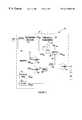
- FIG. 1is a schematic diagram of a supplemental restraint system including a programmed microprocessor for carrying out the deployment method of this invention.
- FIG. 2is a graphical representation of event progression and threshold adjustment determination according to this invention.
- FIG. 3is a logic diagram illustrating the operation of the deployment method of this invention.
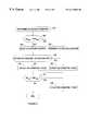
- FIGS. 4-6are flow diagrams representative of computer program instructions executed by the microprocessor of FIG. 1 in carrying out the deployment method of this invention.
- FIG. 4is a main flow diagram
- FIG. 5details a step of the main flow diagram relating to calculation of threshold adjustments
- FIG. 6details a step of the main flow diagram relating to determining when the threshold adjustments should be applied to the threshold.
- FIG. 1generally depicts a vehicle supplemental restraint system in which one or more restraints, such as air bags AB, are deployed in a severe crash event to protect the vehicle occupants.
- the restraintsmay include without limitation, air bags, belt pretensioners, inflatable tubular structures, side curtains, anti-whiplash devices, etc., and it will be understood that such term AB as used herein does not refer exclusively to a particular type of restraint.
- a deployment control systemdesignated generally by the reference numeral 10 , may be packaged as a single electronic module and mounted on a frame element in a central portion of the vehicle.
- the system 10includes a longitudinal acceleration sensor LAS (which may comprise a single sensor or a pair of sensors mounted at an offset angle) for sensing longitudinal acceleration of the vehicle, a microprocessor ⁇ P for receiving the output signal of longitudinal acceleration sensor LAS, and a firing circuit FC which is triggered by microprocessor ⁇ P to deploy the air bags AB in the event of a severe crash.
- the microprocessor ⁇ Pfilters the longitudinal acceleration signal over a predefined interval, or window, to form a windowed velocity signal, referred to herein as ⁇ V WIN .
- the microprocessor ⁇ Pthen adjusts a deployment threshold, referred to herein as a ⁇ V Threshold, based on event progression and secondary crash criteria, and compares ⁇ V WIN to the ⁇ V Threshold. If ⁇ V WIN crosses the ⁇ V Threshold, the microprocessor ⁇ P signals the firing circuit FC to deploy the air bags AB.
- a deployment thresholdreferred to herein as a ⁇ V Threshold
- the ⁇ V Thresholdis set at a default level prior to initiation of a crash event and threshold adjustments are periodically determined and accumulated during the crash event, with the net adjustment value and subsequent adjustment values (if any) being put into effect for purposes of deploying the restraints upon expiration of a delay time initiated at a predefined level of event progression.
- the event progressionis determined by the value of a ⁇ velocity signal ( ⁇ V bias ) biased toward zero, and the threshold adjustments are determined based on secondary measures of crash severity and event progression.
- the net adjustment valueis applied to the deployment threshold prior to expiration of the delay time if certain secondary measures indicate that the crash is especially severe.
- the windowed velocity signal ⁇ V WINmay be calculated according to the expression:
- ACCELis a filtered version of the output of acceleration sensor LAS and w is the window size.
- the window wactually refers to a specified number of successive samples of the acceleration signal. Since the samples are read at a predefined rate, however, the window w also may be viewed as a corresponding time interval.
- the biased velocity signal ⁇ V biasmay be determined by computing a filtered acceleration signal ⁇ V, and then applying a bias “B”.
- ⁇ Vmay be calculated according to the expression:
- bias Bd if ⁇ ⁇ ⁇ ⁇ ⁇ V > d , ⁇ with ⁇ ⁇ d ⁇ ⁇ being ⁇ ⁇ a ⁇ ⁇ positive ⁇ ⁇ integer ⁇ ⁇ ⁇ V if ⁇ ⁇ ⁇ ⁇ ⁇ ⁇ V ⁇ ⁇ d - d if ⁇ ⁇ ⁇ ⁇ V ⁇ - d ( 4 )
- the level of event progressioncan be determined by using windowed velocity ⁇ V WIN within a limited acceleration range, or a filtered version of ⁇ V WIN or ⁇ V.
- ⁇ V biasis used to determine the level of event progression.
- ⁇ V biasis compared to a series of predefined velocity values, referred to herein as progression level thresholds a-d, thereby defining four corresponding stages or levels of event progression; obviously, the number of thresholds, and hence progression levels, may vary from one implementation to another.
- progression level thresholds a-da series of predefined velocity values
- progression level thresholds a-da series of predefined velocity values
- the time designations t 0 -t 6signify times that coincide with ⁇ V bias crossing one of the thresholds a-d, and the event progression level at any given time is indicated at the top of Graph A, and below the time axis of Graph B.
- progression level of the sensed eventis “a” in the time interval t 0 -t 1 , “b” in the time interval t 1 -t 2 , “c” in the time interval t 2 -t 3 , “b” in the time interval t 3 -t 4 , and so on.
- the progression level “a”is indicative of no or very low activity.
- each of the progression levels a-dhave predefined regions corresponding to different levels of the secondary measure, as shown by the vertical columns in Graph B, and the threshold adjustment amount is determined based on which region the secondary signal is in. For example, if the sensed event in is progression level “b”, a set of threshold adjustment rules might be: (1) increase the ⁇ V Threshold by 5 counts if ⁇ V sec , is in region 1 , (2) increase the ⁇ V Threshold by 1 counts if ⁇ V sec , is in region 2 , and (3) decrease the ⁇ V Threshold by 2 counts if ⁇ V sec , is in region 3 .
- the various periodically determined threshold adjustmentsare summed or accumulated to form a net threshold adjustment, but the net threshold adjustment is not put into effect for purposes of deploying the restraints until the expiration of the delay time.
- Threshold adjustments determined after the expiration of the delay timeare applied to the deployment threshold without delay.
- the delay timeis initiated upon attainment of a predefined level of event progression, such as the transition from progression level “a” to progression level “b”.
- the net adjustment valueis applied to the deployment threshold prior to expiration of the delay time if certain secondary measures indicate that the crash is especially severe. For example, the net adjustment value is applied to the deployment threshold immediately if a crash oscillation measure exceeds a predefined level.
- FIG. 3is a logic diagram of deployment control system 10 , illustrating the operation of the microprocessor ⁇ P of FIG. 1 in carrying out the control of this invention.
- the longitudinal acceleration sensor LASproduces an acceleration signal ACCEL
- the microprocessor ⁇ Panalyzes the ACCEL signal, and commands the firing circuit FC to deploy the restraints AB if a sufficiently severe crash event is detected.
- the ACCEL signalis provided as an input to blocks 12 , 14 and 16 .
- Block 12develops a primary measure of crash severity ⁇ V WIN in accordance with equation (1)
- block 14develops a biased velocity signal ⁇ V bias in accordance with equations (2)-(4)
- block 16develops secondary measures of crash severity ⁇ V sec such as a velocity gradient or a velocity oscillation signal.
- the primary measure ⁇ V WINis compared with the active deployment threshold (THR act ) at comparator 18 , and if ⁇ V WIN exceeds THR act the firing circuit FC is activated to deploy the restraints AB.
- the secondary measures ⁇ V secare supplied to block 20 , which determines threshold adjustments T A , as explained above in reference to FIG.
- THR fix and THR initare provided by the microprocessor memory 24 .
- the fixed and moving thresholds THR fix and THR movare supplied as inputs to a switch 26 , which selects either THR fix or THR mov to be the active threshold THR act , depending on the logic level applied to control line 28 .
- control line 28is at a logic zero level, causing switch 26 to select THR fix as the active threshold THR act .
- the components 30 , 32 , 34 and 36cooperate to drive the control line 28 to a logic one level, causing switch 26 to select THR mov as the active threshold THR act .
- the comparator 30compares ⁇ V bias to the timer threshold THR tmr , which may be the same as the progression level threshold “b” described in reference to FIG. 2, for example. When ⁇ V bias exceeds THR tmr , the comparator 30 triggers timer 32 to measure a delay interval, but if ⁇ V bias falls below THR tmr , the timer 32 is reset.
- timer 32The output of timer 32 is provided as an input to OR-gate 34 , so that control line 28 of switch 26 is driven to a logic one state upon expiration of the measured delay interval.
- the comparator 36compares secondary measure ⁇ V sec to the secondary threshold THR sec , and similarly triggers OR-gate 34 to drive control line 28 to a logic one state if ⁇ V sec exceeds THR sec .
- the active threshold THR act used to decide if the restraints AB should be deployedis determined according to THR fix until either ⁇ V sec exceeds THR sec , or ⁇ V bias exceeds THR tmr for the delay time measured by timer 32 .
- the timer threshold THR tmrcorresponds to predetermined level of crash progression
- the secondary threshold THR seccorresponds to a secondary measure indicative of a very severe crash.
- FIG. 3While the logic diagram of FIG. 3 is a useful aid in understanding the operation of the subject control method, it will be understood that the various blocks such as comparators 18 , 30 and 36 are not physically present within the microprocessor ⁇ P, and that the microprocessor ⁇ P carries out the control method by executing a computer program stored in the memory 24 .
- FIGS. 4-6set forth a flow diagram representative of pertinent portions of such a computer program.
- FIG. 4is a main flow diagram
- FIG. 5details a step of the main flow diagram relating to calculation of threshold adjustments
- FIG. 6details a step of the main flow diagram relating to determining when the threshold adjustments should be applied to the threshold.
- the block 100designates a series of instructions executed at the initiation of vehicle operation for initializing various registers, counters, flags and variables to a pre-defined state.
- the moving threshold THR movis initialized at an initial value THR init
- the active deployment threshold THR actis initialized to the fixed value THR fix .
- the blocks 102 and 104are executed to read the filtered output signal ACCEL of the longitudinal acceleration sensor LAS, and to compute various severity measurements, including ⁇ V, ⁇ V bias , ⁇ V win , V sec , and so on.
- Block 106is then executed to determine a net threshold adjustment T A , as described in detail below in reference to FIG. 5 .
- Block 108then limits the magnitude of T A to a limit value, and block 110 adds the new value of T A to the current value of THR mov to update the moving threshold THR mov .
- Block 112determines the activating conditions for application of the moving threshold THR mov , and is detailed in the flow diagram of FIG. 6; in general, the activation conditions are TRUE if the threshold adjustments T A are to be applied, and FALSE if the fixed threshold THR fix is to be used to determine deployment.
- block 114determines that the activation conditions are TRUE
- block 116is executed to set THR act equal to THR mov . Otherwise, block 118 is executed to set THR act equal to THR fix .
- block 120compares the windowed velocity ⁇ V win to the active threshold THR act . If ⁇ V win exceeds THR act , the block 122 is executed to deploy the restraints AB.
- the flow diagram of FIG. 5details the determination of the net threshold adjustment T A .
- the various event progression thresholds a-d, the regions 1 - 4 for each secondary measurement, and the associated threshold adjustment amounts described above in reference to FIG. 2are stored in an adaptation matrix within microprocessor ⁇ P, and a series of progression level masks for each secondary measurement are used to identify corresponding regions and adjustments amounts T A .
- Blocks 130 - 142comprise a nested loop for determining the net threshold adaptation amount T A , taking into account each of the secondary measurements.
- the microprocessor ⁇ Pexecutes the blocks 132 - 140 within the ⁇ V sec loop boundary blocks 130 and 142 , and for each progression level mask L, the microprocessor ⁇ P executes the blocks 134 - 138 within the progression level loop boundary blocks 132 and 140 .
- the current mask Lis applied to the matrix, and the microprocessor ⁇ P determines if the biased velocity ⁇ V bias is within the corresponding progression level thresholds. If not, the mask L for the next progression level is applied to the matrix, as indicated at block 140 .
- block 136determines if the respective secondary measurement ⁇ V sec is within an adaptation region corresponding to the progression level of the mask L, and if so, block 138 adds the corresponding adaptation value to the net threshold adaptation amount T A .
- the adaptation valueis stored in the matrix as a function of the secondary measurement ⁇ V sec and the progression level mask L.
- the blocks 144 - 148are executed to bias the moving threshold THR mov toward THR init if the event progression level is “a”—i.e., no activity.
- Block 144determines if the event progression is at level “a”. If so, block 136 compares THR mov to THR init . If THR mov has been adjusted to a value less than THR init , block 148 sets the net threshold adaptation amount T A to a positive incremental value, referred to in FIG. 5 as + Threshold Recover. Conversely, if THR mov has been adjusted to a value greater than THR init , block 150 sets the net threshold adaptation amount T A to a negative incremental value, referred to in FIG. 5 as ⁇ Threshold Recover.
- Block 160is first executed to determine if ⁇ V bias is greater than the timer threshold THR tmr . If so, block 162 is executed to increment an activation counter; otherwise, block 164 resets the counter to zero. Block 166 then determines if the count of the activation counter exceeds an activation level corresponding a predetermined delay time. If so, block 168 sets the activation condition to TRUE; otherwise, block 170 sets the activation condition to FALSE.
- block 172determines if one or more selected secondary measures ⁇ V sec exceed respective secondary threshold(s) THR sec . If so, block 174 sets the activation condition to TRUE; otherwise, the activation condition remains at the state set by blocks 168 - 170 .
- the deployment method of this inventiondetermines whether restraints should be deployed by providing a deployment threshold that is initially established at a predefined level, by periodically determining thresholds adjustments in the course of the crash event based on one or more secondary measures of crash severity, and by applying the determined adjustments to the deployment threshold (a) at a time determined in relation to a predefined level of crash progression, or (b) when certain secondary measures of crash severity indicate that the crash is especially severe.
- immunityis improved with respect to non-deployment events that cause high acceleration levels early in the progression of the sensed event, without sacrificing sensitivity to deployment events.
Landscapes
- Engineering & Computer Science (AREA)
- Mechanical Engineering (AREA)
- Air Bags (AREA)
Abstract
Description

Claims (9)
Priority Applications (1)
| Application Number | Priority Date | Filing Date | Title |
|---|---|---|---|
| US09/192,523US6219606B1 (en) | 1998-11-16 | 1998-11-16 | Restraint deployment control method having a delayed adaptable deployment threshold |
Applications Claiming Priority (1)
| Application Number | Priority Date | Filing Date | Title |
|---|---|---|---|
| US09/192,523US6219606B1 (en) | 1998-11-16 | 1998-11-16 | Restraint deployment control method having a delayed adaptable deployment threshold |
Publications (1)
| Publication Number | Publication Date |
|---|---|
| US6219606B1true US6219606B1 (en) | 2001-04-17 |
Family
ID=22710030
Family Applications (1)
| Application Number | Title | Priority Date | Filing Date |
|---|---|---|---|
| US09/192,523Expired - LifetimeUS6219606B1 (en) | 1998-11-16 | 1998-11-16 | Restraint deployment control method having a delayed adaptable deployment threshold |
Country Status (1)
| Country | Link |
|---|---|
| US (1) | US6219606B1 (en) |
Cited By (26)
| Publication number | Priority date | Publication date | Assignee | Title |
|---|---|---|---|---|
| US6459975B1 (en)* | 2000-07-21 | 2002-10-01 | Bayerische Motoren Werke Aktiengesellschaft | Method for recognizing the severity of a vehicle collision |
| US6498972B1 (en) | 2002-02-13 | 2002-12-24 | Ford Global Technologies, Inc. | Method for operating a pre-crash sensing system in a vehicle having a countermeasure system |
| US6519519B1 (en) | 2002-02-01 | 2003-02-11 | Ford Global Technologies, Inc. | Passive countermeasure methods |
| US20030057685A1 (en)* | 2001-09-27 | 2003-03-27 | Bayerische Motoren Werke Aktiengesellschaft | Method of triggering a vehicle occupant restraining device |
| US20030076981A1 (en)* | 2001-10-18 | 2003-04-24 | Smith Gregory Hugh | Method for operating a pre-crash sensing system in a vehicle having a counter-measure system |
| US20030139864A1 (en)* | 2002-01-24 | 2003-07-24 | Ford Global Technologies, Inc. | Post collision restraints control module |
| US20030149517A1 (en)* | 2002-02-04 | 2003-08-07 | Murphy Morgan D. | Method for suppressing deployment of an inflatable restraint based on sensed occupant weight |
| US6714847B2 (en)* | 2001-09-18 | 2004-03-30 | Honda Giken Kogyo Kabushiki Kaisha | Collision detecting apparatus for vehicle |
| US6721659B2 (en) | 2002-02-01 | 2004-04-13 | Ford Global Technologies, Llc | Collision warning and safety countermeasure system |
| US20040111200A1 (en)* | 2001-11-29 | 2004-06-10 | Rao Manoharprasad K. | Vehicle sensing based pre-crash threat assessment system |
| US20040133325A1 (en)* | 2003-01-06 | 2004-07-08 | Neal Mark O. | Variation manager for crash sensing algorithms |
| US6775605B2 (en) | 2001-11-29 | 2004-08-10 | Ford Global Technologies, Llc | Remote sensing based pre-crash threat assessment system |
| US6831572B2 (en) | 2002-01-29 | 2004-12-14 | Ford Global Technologies, Llc | Rear collision warning system |
| WO2005037610A1 (en)* | 2003-10-17 | 2005-04-28 | Volkswagen Aktiengesellschaft | Method for generating a disconnection for triggering a passenger protection system of a motor vehicle |
| US7009500B2 (en) | 2002-02-13 | 2006-03-07 | Ford Global Technologies, Llc | Method for operating a pre-crash sensing system in a vehicle having a countermeasure system using stereo cameras |
| US20060052924A1 (en)* | 2004-09-08 | 2006-03-09 | Prakah-Asante Kwaku O | Active adaptation of vehicle restraints for enhanced performance robustness |
| US20060095185A1 (en)* | 2004-11-02 | 2006-05-04 | Calsonic Kansei Corporation | Airbag development control apparatus |
| US20060113778A1 (en)* | 2002-12-11 | 2006-06-01 | Keihin Corporation | Air bag device start control device |
| EP1957320A4 (en)* | 2005-12-06 | 2010-04-21 | Autoliv Dev | CRASH DETECTION APPARATUS |
| WO2014184041A1 (en)* | 2013-05-13 | 2014-11-20 | Robert Bosch Gmbh | Device for controlling personal protection means in a vehicle |
| US20150051796A1 (en)* | 2013-08-14 | 2015-02-19 | Infineon Technologies Ag | Crash detection |
| WO2015171062A1 (en)* | 2014-05-09 | 2015-11-12 | Autoliv Development Ab | Activation of pedestrian protection mechanism |
| US20160140781A1 (en)* | 2013-06-18 | 2016-05-19 | Robert Bosch Gmbh | Method and device for determining a collision characteristic of a vehicle collision |
| US20160325702A1 (en)* | 2012-10-24 | 2016-11-10 | Autoliv Development Ab | Control device for occupant protection device |
| US10493937B2 (en) | 2017-02-01 | 2019-12-03 | Ford Global Technologies, Llc | Restraint device deployment calibration |
| US20200384935A1 (en)* | 2019-06-04 | 2020-12-10 | B/E Aerospace, Inc. | Safety system initiator with electronically adjustable fire time |
Citations (7)
| Publication number | Priority date | Publication date | Assignee | Title |
|---|---|---|---|---|
| US5014810A (en)* | 1989-02-18 | 1991-05-14 | Robert Bosch Gmbh | Method for controlling the release of passenger restraint systems |
| US5538099A (en)* | 1994-05-27 | 1996-07-23 | Trw Vehicle Safety Systems Inc. | Method and apparatus for controlling an air bag restraint system |
| US5608628A (en)* | 1991-05-31 | 1997-03-04 | Messerschmitt-Bolkow-Blohm Gmbh | Process and apparatus for detecting vehicle impact |
| USRE36122E (en)* | 1989-02-18 | 1999-03-02 | Robert Bosch Gmbh | Method for controlling the release of passenger restraint systems |
| US5964817A (en)* | 1998-11-09 | 1999-10-12 | Delco Electronics Corp. | Impact characterizing deployment control method for an automotive restraint system |
| US5969599A (en)* | 1998-11-09 | 1999-10-19 | Delco Electronics Corp. | Restraint deployment control method having an adaptable deployment threshold |
| US5999871A (en)* | 1996-08-05 | 1999-12-07 | Delphi Technologies, Inc. | Control method for variable level airbag inflation |
- 1998
- 1998-11-16USUS09/192,523patent/US6219606B1/ennot_activeExpired - Lifetime
Patent Citations (7)
| Publication number | Priority date | Publication date | Assignee | Title |
|---|---|---|---|---|
| US5014810A (en)* | 1989-02-18 | 1991-05-14 | Robert Bosch Gmbh | Method for controlling the release of passenger restraint systems |
| USRE36122E (en)* | 1989-02-18 | 1999-03-02 | Robert Bosch Gmbh | Method for controlling the release of passenger restraint systems |
| US5608628A (en)* | 1991-05-31 | 1997-03-04 | Messerschmitt-Bolkow-Blohm Gmbh | Process and apparatus for detecting vehicle impact |
| US5538099A (en)* | 1994-05-27 | 1996-07-23 | Trw Vehicle Safety Systems Inc. | Method and apparatus for controlling an air bag restraint system |
| US5999871A (en)* | 1996-08-05 | 1999-12-07 | Delphi Technologies, Inc. | Control method for variable level airbag inflation |
| US5964817A (en)* | 1998-11-09 | 1999-10-12 | Delco Electronics Corp. | Impact characterizing deployment control method for an automotive restraint system |
| US5969599A (en)* | 1998-11-09 | 1999-10-19 | Delco Electronics Corp. | Restraint deployment control method having an adaptable deployment threshold |
Cited By (45)
| Publication number | Priority date | Publication date | Assignee | Title |
|---|---|---|---|---|
| US6459975B1 (en)* | 2000-07-21 | 2002-10-01 | Bayerische Motoren Werke Aktiengesellschaft | Method for recognizing the severity of a vehicle collision |
| US6714847B2 (en)* | 2001-09-18 | 2004-03-30 | Honda Giken Kogyo Kabushiki Kaisha | Collision detecting apparatus for vehicle |
| US6848712B2 (en)* | 2001-09-27 | 2005-02-01 | Bayerische Motoren Werke Aktiengesellschaft | Method of triggering a vehicle occupant restraining device |
| US20030057685A1 (en)* | 2001-09-27 | 2003-03-27 | Bayerische Motoren Werke Aktiengesellschaft | Method of triggering a vehicle occupant restraining device |
| EP1298010A3 (en)* | 2001-09-27 | 2003-11-12 | Bayerische Motoren Werke Aktiengesellschaft | Method for triggering a passenger restraining device in a vehicle |
| US20030076981A1 (en)* | 2001-10-18 | 2003-04-24 | Smith Gregory Hugh | Method for operating a pre-crash sensing system in a vehicle having a counter-measure system |
| US20040111200A1 (en)* | 2001-11-29 | 2004-06-10 | Rao Manoharprasad K. | Vehicle sensing based pre-crash threat assessment system |
| US6819991B2 (en) | 2001-11-29 | 2004-11-16 | Ford Global Technologies, Llc | Vehicle sensing based pre-crash threat assessment system |
| US6775605B2 (en) | 2001-11-29 | 2004-08-10 | Ford Global Technologies, Llc | Remote sensing based pre-crash threat assessment system |
| US20030139864A1 (en)* | 2002-01-24 | 2003-07-24 | Ford Global Technologies, Inc. | Post collision restraints control module |
| US7158870B2 (en) | 2002-01-24 | 2007-01-02 | Ford Global Technologies, Llc | Post collision restraints control module |
| US6831572B2 (en) | 2002-01-29 | 2004-12-14 | Ford Global Technologies, Llc | Rear collision warning system |
| US6721659B2 (en) | 2002-02-01 | 2004-04-13 | Ford Global Technologies, Llc | Collision warning and safety countermeasure system |
| US6519519B1 (en) | 2002-02-01 | 2003-02-11 | Ford Global Technologies, Inc. | Passive countermeasure methods |
| US20030149517A1 (en)* | 2002-02-04 | 2003-08-07 | Murphy Morgan D. | Method for suppressing deployment of an inflatable restraint based on sensed occupant weight |
| US6850825B2 (en) | 2002-02-04 | 2005-02-01 | Delphi Technologies, Inc. | Method for suppressing deployment of an inflatable restraint based on sensed occupant weight |
| US6498972B1 (en) | 2002-02-13 | 2002-12-24 | Ford Global Technologies, Inc. | Method for operating a pre-crash sensing system in a vehicle having a countermeasure system |
| US7009500B2 (en) | 2002-02-13 | 2006-03-07 | Ford Global Technologies, Llc | Method for operating a pre-crash sensing system in a vehicle having a countermeasure system using stereo cameras |
| US20060113778A1 (en)* | 2002-12-11 | 2006-06-01 | Keihin Corporation | Air bag device start control device |
| US7120525B2 (en)* | 2002-12-11 | 2006-10-10 | Keihin Corporation | Activation control device for airbag device |
| US20040133325A1 (en)* | 2003-01-06 | 2004-07-08 | Neal Mark O. | Variation manager for crash sensing algorithms |
| US6999863B2 (en)* | 2003-01-06 | 2006-02-14 | General Motors Corporation | Variation manager for crash sensing algorithms |
| WO2005037610A1 (en)* | 2003-10-17 | 2005-04-28 | Volkswagen Aktiengesellschaft | Method for generating a disconnection for triggering a passenger protection system of a motor vehicle |
| WO2005035320A3 (en)* | 2003-10-17 | 2007-07-26 | Volkswagen Ag | Pedestrian protection system for a motor vehicle |
| US20060052924A1 (en)* | 2004-09-08 | 2006-03-09 | Prakah-Asante Kwaku O | Active adaptation of vehicle restraints for enhanced performance robustness |
| US7236865B2 (en) | 2004-09-08 | 2007-06-26 | Ford Global Technologies, Llc | Active adaptation of vehicle restraints for enhanced performance robustness |
| US7509196B2 (en)* | 2004-11-02 | 2009-03-24 | Calsonic Kansei Corporation | Airbag development control apparatus |
| US20060095185A1 (en)* | 2004-11-02 | 2006-05-04 | Calsonic Kansei Corporation | Airbag development control apparatus |
| EP1957320A4 (en)* | 2005-12-06 | 2010-04-21 | Autoliv Dev | CRASH DETECTION APPARATUS |
| US20160325702A1 (en)* | 2012-10-24 | 2016-11-10 | Autoliv Development Ab | Control device for occupant protection device |
| US9751483B2 (en)* | 2012-10-24 | 2017-09-05 | Autoliv Development Ab | Control device for occupant protection device |
| US10077017B2 (en) | 2013-05-13 | 2018-09-18 | Robert Bosch Gmbh | Device for controlling personal protection means in a vehicle |
| WO2014184041A1 (en)* | 2013-05-13 | 2014-11-20 | Robert Bosch Gmbh | Device for controlling personal protection means in a vehicle |
| CN105377636A (en)* | 2013-05-13 | 2016-03-02 | 罗伯特·博世有限公司 | Device for controlling personal protection means in a vehicle |
| CN105377636B (en)* | 2013-05-13 | 2018-05-22 | 罗伯特·博世有限公司 | For controlling the equipment of the person-protecting means in vehicle |
| US20160140781A1 (en)* | 2013-06-18 | 2016-05-19 | Robert Bosch Gmbh | Method and device for determining a collision characteristic of a vehicle collision |
| US10186090B2 (en)* | 2013-06-18 | 2019-01-22 | Robert Bosch Gmbh | Method and device for determining a collision characteristic of a vehicle collision |
| US9718425B2 (en)* | 2013-08-14 | 2017-08-01 | Infineon Technologies Ag | Crash detection |
| US20150051796A1 (en)* | 2013-08-14 | 2015-02-19 | Infineon Technologies Ag | Crash detection |
| CN106458127A (en)* | 2014-05-09 | 2017-02-22 | 奥托立夫开发公司 | Activation of pedestrian protection mechanism |
| WO2015171062A1 (en)* | 2014-05-09 | 2015-11-12 | Autoliv Development Ab | Activation of pedestrian protection mechanism |
| CN106458127B (en)* | 2014-05-09 | 2019-05-17 | 维宁尔瑞典公司 | Activation of pedestrian protection agencies |
| US10493937B2 (en) | 2017-02-01 | 2019-12-03 | Ford Global Technologies, Llc | Restraint device deployment calibration |
| US20200384935A1 (en)* | 2019-06-04 | 2020-12-10 | B/E Aerospace, Inc. | Safety system initiator with electronically adjustable fire time |
| US11034318B2 (en)* | 2019-06-04 | 2021-06-15 | B/E Aerospace, Inc. | Safety system initiator with electronically adjustable fire time |
Similar Documents
| Publication | Publication Date | Title |
|---|---|---|
| US6219606B1 (en) | Restraint deployment control method having a delayed adaptable deployment threshold | |
| US5969599A (en) | Restraint deployment control method having an adaptable deployment threshold | |
| US6430489B1 (en) | Restraint deployment control method with feed-forward adjustment of deployment threshold | |
| US6198387B1 (en) | Restraint deployment control with central and frontal crash sensing | |
| US5964817A (en) | Impact characterizing deployment control method for an automotive restraint system | |
| US6151540A (en) | Dynamic occupant position detection system and method for a motor vehicle | |
| KR101805672B1 (en) | Method and apparatus for controlling an actuatable restraining device using multi-region enchanced discrimination | |
| US5394326A (en) | Air bag deployment control system and method | |
| US6236308B1 (en) | Restraint deployment control method with speed-dependent adjustment of deployment threshold | |
| JP4053789B2 (en) | Vehicle rollover detection system | |
| US6512969B1 (en) | Vehicle sensing system using biased severity measure | |
| US5430649A (en) | SIR deployment method based on occupant displacement and crash severity | |
| US7269483B2 (en) | Multiple algorithm event discrimination method | |
| US5418722A (en) | SIR deployment method with rough road immunity | |
| US6496764B1 (en) | Vehicle impact-sensing method with improved severity discrimination | |
| US7422087B2 (en) | Method and system for detecting vehicle rollover events | |
| EP0665140A2 (en) | Method and apparatus for controlling an actuatable restraining device | |
| US6636794B2 (en) | Passive safety system | |
| JPH10505035A (en) | System and method for adjusting crash identification measurements | |
| EP3611060B1 (en) | Control device, and method for controlling protective device | |
| US6353783B1 (en) | Method and device for forming a deployment criterion for a restraint system | |
| EP2020338B1 (en) | A method and system for detecting a vehicle rollover, in particular a soil trip rollover | |
| US6157881A (en) | Supplemental restraint rear impact deployment control method | |
| US7660655B2 (en) | Supplemental restraint deployment method with displacement-based deployment immunity | |
| KR100360213B1 (en) | How to dampen collision discrimination measurements |
Legal Events
| Date | Code | Title | Description |
|---|---|---|---|
| AS | Assignment | Owner name:DELCO ELECTRONICS CORPORATION, INDIANA Free format text:ASSIGNMENT OF ASSIGNORS INTEREST;ASSIGNORS:WESSELS, GERHARD F.;DALUM, JOSEPH THOMAS;REEL/FRAME:009607/0735 Effective date:19981106 | |
| STCF | Information on status: patent grant | Free format text:PATENTED CASE | |
| FPAY | Fee payment | Year of fee payment:4 | |
| SULP | Surcharge for late payment | ||
| AS | Assignment | Owner name:DELPHI TECHNOLOGIES, INC., MICHIGAN Free format text:ASSIGNMENT OF ASSIGNORS INTEREST;ASSIGNOR:DELCO ELECTRONICS CORPORATION;REEL/FRAME:016700/0623 Effective date:20050701 | |
| AS | Assignment | Owner name:JPMORGAN CHASE BANK, N.A., TEXAS Free format text:SECURITY AGREEMENT;ASSIGNOR:DELPHI TECHNOLOGIES, INC.;REEL/FRAME:016237/0402 Effective date:20050614 | |
| AS | Assignment | Owner name:DELPHI TECHNOLOGIES, INC., MICHIGAN Free format text:RELEASE OF SECURITY AGREEMENT;ASSIGNOR:JPMORGAN CHASE BANK, N.A.;REEL/FRAME:020808/0583 Effective date:20080225 | |
| FPAY | Fee payment | Year of fee payment:8 | |
| FPAY | Fee payment | Year of fee payment:12 | |
| AS | Assignment | Owner name:DBD CREDIT FUNDING, LLC, NEW YORK Free format text:SECURITY INTEREST;ASSIGNORS:MARATHON PATENT GROUP, INC.;LOOPBACK TECHNOLOGIES, INC.;REEL/FRAME:034873/0255 Effective date:20150129 | |
| AS | Assignment | Owner name:LOOPBACK TECHNOLOGIES, INC., VIRGINIA Free format text:ASSIGNMENT OF ASSIGNORS INTEREST;ASSIGNOR:DELPHI TECHNOLOGIES, INC.;REEL/FRAME:035311/0212 Effective date:20131218 | |
| AS | Assignment | Owner name:DBD CREDIT FUNDING LLC, AS COLLATERAL AGENT, NEW Y Free format text:SECURITY INTEREST;ASSIGNORS:MOTHEYE TECHNOLOGIES, LLC;SYNCHRONICITY IP LLC;TRAVERSE TECHNOLOGIES CORP.;AND OTHERS;REEL/FRAME:041333/0001 Effective date:20170110 | |
| AS | Assignment | Owner name:APTIV TECHNOLOGIES LIMITED, BARBADOS Free format text:ASSIGNMENT OF ASSIGNORS INTEREST;ASSIGNOR:DELPHI TECHNOLOGIES INC.;REEL/FRAME:047143/0874 Effective date:20180101 |