US6219543B1 - Energy detection device - Google Patents
Energy detection deviceDownload PDFInfo
- Publication number
- US6219543B1 US6219543B1US09/089,559US8955998AUS6219543B1US 6219543 B1US6219543 B1US 6219543B1US 8955998 AUS8955998 AUS 8955998AUS 6219543 B1US6219543 B1US 6219543B1
- Authority
- US
- United States
- Prior art keywords
- energy
- antenna
- network
- coupled
- operational amplifier
- Prior art date
- Legal status (The legal status is an assumption and is not a legal conclusion. Google has not performed a legal analysis and makes no representation as to the accuracy of the status listed.)
- Expired - Fee Related
Links
Images


Classifications
- G—PHYSICS
- G06—COMPUTING OR CALCULATING; COUNTING
- G06Q—INFORMATION AND COMMUNICATION TECHNOLOGY [ICT] SPECIALLY ADAPTED FOR ADMINISTRATIVE, COMMERCIAL, FINANCIAL, MANAGERIAL OR SUPERVISORY PURPOSES; SYSTEMS OR METHODS SPECIALLY ADAPTED FOR ADMINISTRATIVE, COMMERCIAL, FINANCIAL, MANAGERIAL OR SUPERVISORY PURPOSES, NOT OTHERWISE PROVIDED FOR
- G06Q20/00—Payment architectures, schemes or protocols
- G06Q20/30—Payment architectures, schemes or protocols characterised by the use of specific devices or networks
- G06Q20/34—Payment architectures, schemes or protocols characterised by the use of specific devices or networks using cards, e.g. integrated circuit [IC] cards or magnetic cards
- G06Q20/342—Cards defining paid or billed services or quantities
- G—PHYSICS
- G01—MEASURING; TESTING
- G01R—MEASURING ELECTRIC VARIABLES; MEASURING MAGNETIC VARIABLES
- G01R29/00—Arrangements for measuring or indicating electric quantities not covered by groups G01R19/00 - G01R27/00
- G01R29/08—Measuring electromagnetic field characteristics
- G01R29/0864—Measuring electromagnetic field characteristics characterised by constructional or functional features
- G01R29/0878—Sensors; antennas; probes; detectors
- G—PHYSICS
- G07—CHECKING-DEVICES
- G07F—COIN-FREED OR LIKE APPARATUS
- G07F13/00—Coin-freed apparatus for controlling dispensing or fluids, semiliquids or granular material from reservoirs
- G07F13/02—Coin-freed apparatus for controlling dispensing or fluids, semiliquids or granular material from reservoirs by volume
- G07F13/025—Coin-freed apparatus for controlling dispensing or fluids, semiliquids or granular material from reservoirs by volume wherein the volume is determined during delivery
- G—PHYSICS
- G07—CHECKING-DEVICES
- G07F—COIN-FREED OR LIKE APPARATUS
- G07F7/00—Mechanisms actuated by objects other than coins to free or to actuate vending, hiring, coin or paper currency dispensing or refunding apparatus
- G07F7/02—Mechanisms actuated by objects other than coins to free or to actuate vending, hiring, coin or paper currency dispensing or refunding apparatus by keys or other credit registering devices
- G07F7/025—Mechanisms actuated by objects other than coins to free or to actuate vending, hiring, coin or paper currency dispensing or refunding apparatus by keys or other credit registering devices by means, e.g. cards, providing billing information at the time of purchase, e.g. identification of seller or purchaser, quantity of goods delivered or to be delivered
Definitions
- the present inventionrelates to the detection of energy levels and field strength indications of RF transponder devices. Specifically, energy detection and field strength indication in the microwave energy range. More specifically, the invention is useful in the consumable energy automation dispensing arts.
- a customeris issued a small handheld transponder device about the size of a key-chain which is encoded with identification and account data pertinent to that particular customer.
- the transponder deviceneed not be handheld but may also be mounted somewhere in the car such as the inside area of the front or rear windshield. Further, the transponder device may be active or passive depending on the level of functionality desired by a customer. Active transponders have increased memory and require a power source such as a battery contained within the device to facilitate memory storage. Passive transponders possess limited memory and require no battery. The transponders can be pre-programmed with additional information about the customer such as whether a receipt of a given transaction is desired.
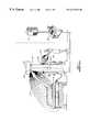
- FIG. 1illustrates a prior art handheld and car mounted transponder system for purchasing fuel at a fuel dispensing device 110 without the need for direct interaction with an attendant or a point-of-sale (POS) device.
- POSpoint-of-sale
- the systemworks similarly for a handheld transponder tag 124 communicating via antenna 126 with interrogation device 118 .
- the chief difference between car mounted transponder tags 112 and handheld transponder tags 124is the placement of antenna 126 and the effective range 114 of the handheld transponder tag 124 .
- the present inventionis an energy detection diagnostic device for reading and evaluating several critical factors pertaining to the RF communication of signals between transponder tags and interrogation devices. Field strength and field orientation measurements are determined in order to verify optimal performance of the system. Further, the present invention performs these measurements in an unobtrusive manner that does not require the system to be shut down and mechanically accessed.
- the present inventioncomprises a handheld energy detection diagnostic device for detecting and measuring high frequency energy.
- the devicecomprises a pick-up or antenna mechanism coupled to electronics circuitry to receive and evaluate RF energy characteristics being emitted from an interrogation device, for instance. Based upon the level of received energy and the level of expected energy, the device presents a ratio to the operator indicating a degree of performance currently being experienced at a particular interrogation device.
- the deviceis small enough to be handheld and included with a technician's standard set of tools.
- FIG. 1illustrates a prior art or conventional handheld and car mounted transponder system for purchasing fuel at a gas pump without the need for direct interaction with an attendant or a point-of-sale (POS) device;
- POSpoint-of-sale
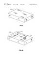
- FIG. 2 and FIG. 2Aare illustrating the energy detection device of the present invention as seen from the outside top;
- FIG. 3is a top level block diagram of the logic process employed by the energy detection device
- FIG. 4is a schematic illustrating the basic circuit within the energy detection device
- FIG. 4Ais a schematic illustrating one embodiment of the pick-up circuitry suitable for high frequency energy
- FIG. 4Bis a schematic illustrating one embodiment of the pick-up circuitry suitable for low frequency inductive energy
- FIG. 4Cis a schematic illustrating one embodiment of the pick-up circuitry suitable for both low and high frequency energy
- FIG. 5is a diagram illustrating an energy detection device testing a system that is malfunctioning
- FIG. 6is a diagram illustrating an energy detection device testing a system that is functioning properly
- FIG. 7is a block diagram illustrating the steps for measuring axial ratio using two antennas.
- FIG. 8is a block diagram illustrating the steps for measuring axial ratio using a single antenna.
- the preferred embodiment of the present inventioncomprises a handheld diagnostic box-like device (as shown in FIGS. 2 and 2A) capable of determining the output RF field strength of an interrogation box transponder.
- An interrogation box transponder systemis shown in FIG. 1 and has been previously described in the related art section of the present application.
- the operatorcan also determine the effective field dimensions or geometry of the interrogation box's antenna.
- Field geometryis important in consumable energy dispensing since an automobile being filled will necessarily be in a location proximate to the consumable energy dispensing machine.
- the automobile's tankmust be within the reach of the dispenser's hose.
- the interrogation box's field geometrymust be sufficient to encompass a transponder tag mounting location that is virtually anywhere on the car.
- the considerations for measuring field geometryare slightly different since the transponder tag is more mobile than that of a car mounted transponder tag. For instance, a handheld transponder tag can be brought very close to the fuel dispensing machine in order for a transaction to take place. Nevertheless, it is still important to know and determine the field strength and field geometry of handheld transponder tag systems in order to ensure an interrogation box system is operating at sufficient levels.
- FIGS. 2 and 2Aillustrate the energy detection diagnostic device of the present invention.
- FIG. 2shows a “black box” generally designated 200 containing electronics circuitry (not shown) for detecting and evaluating the presence of an RF field.
- FIG. 2Aillustrates the same general device 200 having a video display 210 for visually indicating the status results of the RF field check.
- FIG. 2Aalso shows a speaker 212 for audibly indicating to the operator via a specific tone or beep the status results of the RF field check.
- FIG. 3is a block diagram of the system logic for the energy detection device of the present invention.
- the energy detection diagnostic deviceis placed within the expected transmission and reception range of an automated consumable energy system.
- a low value reference voltage 310is applied to an RF detector circuit block 320 .
- the output of the RF detector circuit block 320 and a higher value reference voltage 330are applied to a compare block 340 .
- compare block 340comprises an operational amplifier circuit.
- the results of compare block 340are forwarded to an output block 350 .
- Output block 350can indicate the operational status of the system in either an audio or video fashion.
- FIG. 4illustrates the circuitry within the energy detection diagnostic device of the present invention.
- the energy detection deviceemploys a pick-up mechanism 450 coupled to an antenna (not shown) to collect RF energy.
- Three pick-up mechanism 450 embodimentsare illustrated in FIGS. 4A, 4 B, and 4 C, respectively.
- the pick-up mechanism 450 of FIG. 4Acomprises an RC network ( 435 and 440 ) and diode 430 to create a DC signal from the AC RF signal received at the antenna.
- the detected RF energyis fed to the RC network ( 435 and 440 ) which develops a DC value in the presence of an RF field.
- a reference voltageis used to develop a known stable voltage on the order of 1.2 volts. This reference voltage will not vary with time.
- a resistive voltage divider( 420 and 425 ) is employed to create a second stable voltage on the order of 5 millivolts below the 1.2 v reference voltage.
- the second, lower, voltageis coupled to the negative terminal of the RC network ( 435 and 440 ).
- the positive terminal of the RC network( 435 and 440 ) is coupled to the negative input of an operational amplifier 445 .
- the positive input of the operational amplifier 445is coupled to the higher of the reference voltages.
- the operational amplifier 445Upon sufficient presence of RF energy, the operational amplifier 445 will trigger a transistor 470 which in turn drives an output device 475 notifying the operator of the energy detection device of the presence of RF energy. In its quiescent state, the entire network draws a minimal current of less than 50 microamps. The presence of an RF energy field is enough to have the operational amplifier 445 activate transistor 470 which in turn drives output device 475 .
- the pick-up mechanism 450 configuration of FIG. 4Ais most suitable for high frequency energy systems.
- the other two pick-up mechanisms 450operate similarly to that of FIG. 4 A.
- One of ordinary skill in the artcan easily substitute one pick-up mechanism 450 for another without departing from the spirit or scope of the present invention.
- the choice of pick-up mechanismsis based upon the frequency of energy desired to detect. For instance, the pick-up mechanism 450 configuration illustrated in FIG. 4B is most suitable for low frequency inductive energy systems while the pick-up mechanism 450 configuration illustrated in FIG. 4C is suitable for both low and high frequency energy systems.
- the output device 475can be a visual computer display such as a meter, an LCD, an LED, or any other known in the art.
- the output device 475can also be an audio alert such as a beep or a tone or a series of same which serve to notify the operator of the energy detection device of the presence of RF energy.
- An audio alertis sometimes preferable, especially if the device is being operated in an area of bright lighting which could hinder attempts to read a visual display.
- Prior deviceshave been developed that simply measure the RF power emitted by a system for use by technicians to diagnose and correct the system.
- a significant drawback in such devicesis the inability to quickly and unobtrusively ascertain whether a return signal has been received by the system. That is, such devices can only determine how well a system is transmitting not how well a system is responding to received data. At least not in a quick and unobtrusive manner.
- the prior art means for verifying system responseutilizes RFID (Radio Frequency Identification) test tags. This is both obtrusive and time consuming. It is obtrusive because it ties up the system being tested since the diagnostics of the system have to be accessed thereby taking the system “offline” while being tested. It is time consuming because, while a simple response test using only the RFID test tag can be conducted, test tags are coded to be rejected and must be cleared by a technician from the dispenser before another customer transaction can occur.
- RFIDRadio Frequency Identification
- the present inventionuses a signal testing tool and a test tag in combination to test the effectiveness of the system forward and return RF links. Moreover, it is done unobtrusively on a low level that does not require interaction with other parts of the system.
- FIGS. 5 and 6illustrate test sequences for a malfunctioning and properly operating system.
- diagnostic devicessimply put out a tone to mimic the pulsing RF transmission pattern of the RFID transceiver of the system being tested.
- the energy detection diagnostic device 510 of the present inventionreads the transmission pattern of the dispenser mounted antennas 520 , 530 and also provides a beeping tone that mimics the rate of the transmission, the relative RF signal strength, and the transmission pattern of the system's transceiver. Upon detecting a test transponder signal, the system modifies the normal transmission pattern to indicate a received signal. If a technician holds the energy detection diagnostic device proximate to a receive/transmit antenna pair 520 , 530 and hears only the normal transmission tone of the transceiver 540 , then the technician will know that the return link is malfunctioning or weak because the transmission pattern was not altered.
- the technicianwill hear the test tag response which is audibly distinguishable from the normal transmission tone.
- the techniciancan quickly and unobtrusively determine by the tone of the return signal if the system's transceiver is receiving RF data from the tag. Use of the system is not impacted during performance of the test.
- a first alternative embodiment of the present inventionincorporates increased diagnostic processing within the energy detection device.
- the increased processingcalculates a ratio between measured RF field strength and expected RF field strength thereby yielding a more precise indication of a particular system's operating condition.
- Output resultsare displayed to the operator utilizing the ratio which permits the operator to determine instantaneously how well and to what degree the system is operating.
- the ratio circuitis essentially a means for providing an evaluation of the axial ratio of the field around the transmitting antenna.
- Axial ratio measurementsprovide a means for determining whether an antenna is performing properly.
- the antennahas a preferred orientation in any incident electromagnetic field. If the antenna is oriented at right angles to the electrical portion of the incident field, there will be minimal pickup, and minimal performance.
- the transmitting antennais typically a circularly polarized antenna. Circularly polarized antennas are constructed in a manner which causes the electromagnetic field to rotate after leaving the antenna.
- the quality of the circular polarizationmay be affected, causing for example, a strengthening of the electrical component in the horizontal axis, and a related weakening in the vertical axis. This would translate to variability in transponder tag sensitivity related to transponder tag orientation.
- the axial ratio measurementprovides an evaluation of the electrical field strength in a first plane versus the electrical field strength in a second orthogonal plane. Two approaches are presented for determining axial ratio and they are illustrated in the block diagrams of FIGS. 7 and 8.
- the first approachis illustrated in FIG. 7 and entails using two orthogonal antennas 710 , 720 to capture energy in two orthogonal planes.
- the captured energy signalscan then be optionally passed through a pre-amplifier 730 in order to increase the effective range of the test.
- the signal strength of each antenna 710 , 720is detected 740 and passed to a processing block 750 which calculates the axial ratio of the two signals.
- the axial ratiocan be displayed, or the ratio could be evaluated, and turned into a go/no-go indication. Either way, the results are displayed 760 to a technician.
- the second approachuses a single linearly polarized antenna 810 .
- Antenna 810captures the present RF energy and is optionally amplified 820 before a strength measurement is detected 830 .
- the signalis then passed to a processing block 850 which captures the first signal reading.
- the antenna 810is then rotated 90 degrees and the process is repeated to the point where processing block 850 captures the second signal reading.
- the processing block 850would then calculate the ratio of the two readings to determine the axial ratio. Similarly, the results of the axial ratio calculation are displayed 860 to a technician.
- the second approachis advantageous since it avoids the problems of standing waves, and the measurement can be taken at one point in space.
- the present inventionis not limited in scope to systems and methods for detecting RF field energy emitted by automated fuel dispensing systems.
- the present inventionmay be utilized for detecting RF field energy emitted by other automated consumable energy dispensing systems including, but not limited to, fossil fuels and electrically stored energy.
- the principles disclosed hereinare equally applicable to detection of RF energy for systems other than consumable energy automated dispensing systems.
- the foregoingis illustrative of the present invention and is not to be construed as limiting thereof. Although a few exemplary embodiments of this invention have been described, those skilled in the art will readily appreciate that many modifications are possible in the exemplary embodiments without materially departing from the novel teachings and advantages of this invention. Accordingly, all such modifications are intended to be included within the scope of this invention as defined in the claims.
Landscapes
- Physics & Mathematics (AREA)
- General Physics & Mathematics (AREA)
- Engineering & Computer Science (AREA)
- Business, Economics & Management (AREA)
- Electromagnetism (AREA)
- Microelectronics & Electronic Packaging (AREA)
- Computer Networks & Wireless Communication (AREA)
- Accounting & Taxation (AREA)
- Strategic Management (AREA)
- General Business, Economics & Management (AREA)
- Theoretical Computer Science (AREA)
- Arrangements For Transmission Of Measured Signals (AREA)
Abstract
Description
The present invention relates to the detection of energy levels and field strength indications of RF transponder devices. Specifically, energy detection and field strength indication in the microwave energy range. More specifically, the invention is useful in the consumable energy automation dispensing arts.
In the world of consumable energy automation, recent developments and advancements now permit customers to fill their automobiles without having to interact with an attendant or an automated device such as a credit card reader. The chief benefits include safety and simplicity. Customers no longer need to expose wallets or purses in search of a credit card, a debit card, or cash.
A customer is issued a small handheld transponder device about the size of a key-chain which is encoded with identification and account data pertinent to that particular customer. The transponder device need not be handheld but may also be mounted somewhere in the car such as the inside area of the front or rear windshield. Further, the transponder device may be active or passive depending on the level of functionality desired by a customer. Active transponders have increased memory and require a power source such as a battery contained within the device to facilitate memory storage. Passive transponders possess limited memory and require no battery. The transponders can be pre-programmed with additional information about the customer such as whether a receipt of a given transaction is desired.
FIG. 1 illustrates a prior art handheld and car mounted transponder system for purchasing fuel at afuel dispensing device 110 without the need for direct interaction with an attendant or a point-of-sale (POS) device. When a car mountedtransponder tag 112 is brought within theeffective range 114 of anantenna 116 coupled tointerrogation device 118 fixed within or on a fueldispensing pump device 110, theinterrogation device 118 communicates with the customer's car mountedtransponder tag 112 obtaining the requisite identification and account information regarding the transaction about to be made with that customer. Theinterrogation device 118 is further connected to a network computer point-of-sale (POS)device 120 for authorizing the requested transaction with acentral computer 122. The system works similarly for ahandheld transponder tag 124 communicating viaantenna 126 withinterrogation device 118. The chief difference between car mountedtransponder tags 112 andhandheld transponder tags 124 is the placement ofantenna 126 and theeffective range 114 of thehandheld transponder tag 124.
For such a retail consumable energy automation system to work reliably it is imperative that the electronics equipment perform at optimum levels at all times. In order to ensure such reliability, an unobtrusive test of the interrogation device is desirable to verify signals are being sent and received without any loss or corruption of data. Moreover, it is desirable to know the field strength of the aforementioned system in order to verify that the system has a sufficient effective range of operation.
The present invention is an energy detection diagnostic device for reading and evaluating several critical factors pertaining to the RF communication of signals between transponder tags and interrogation devices. Field strength and field orientation measurements are determined in order to verify optimal performance of the system. Further, the present invention performs these measurements in an unobtrusive manner that does not require the system to be shut down and mechanically accessed.
The present invention comprises a handheld energy detection diagnostic device for detecting and measuring high frequency energy. The device comprises a pick-up or antenna mechanism coupled to electronics circuitry to receive and evaluate RF energy characteristics being emitted from an interrogation device, for instance. Based upon the level of received energy and the level of expected energy, the device presents a ratio to the operator indicating a degree of performance currently being experienced at a particular interrogation device. The device is small enough to be handheld and included with a technician's standard set of tools.
It is an object of the present invention to provide a device for measuring the field strength of a deployed interrogation device/antenna configuration.
It is a further object of the invention to provide a device for indicating the electric field orientation of a deployed interrogation device/antenna configuration.
It is still another object of the present invention to provide a device that indicates to the operator a relative measurement indicating a degree of performance of a deployed interrogation device/antenna configuration with respect to field strength and electric field orientation.
Further objects of the invention will become apparent to those skilled in the art with reference to the accompanying figures and written description below.
FIG. 1 illustrates a prior art or conventional handheld and car mounted transponder system for purchasing fuel at a gas pump without the need for direct interaction with an attendant or a point-of-sale (POS) device;
FIG.2 and FIG. 2A are illustrating the energy detection device of the present invention as seen from the outside top;
FIG. 3 is a top level block diagram of the logic process employed by the energy detection device;
FIG. 4 is a schematic illustrating the basic circuit within the energy detection device;
FIG. 4A is a schematic illustrating one embodiment of the pick-up circuitry suitable for high frequency energy;
FIG. 4B is a schematic illustrating one embodiment of the pick-up circuitry suitable for low frequency inductive energy;
FIG. 4C is a schematic illustrating one embodiment of the pick-up circuitry suitable for both low and high frequency energy;
FIG. 5 is a diagram illustrating an energy detection device testing a system that is malfunctioning;
FIG. 6 is a diagram illustrating an energy detection device testing a system that is functioning properly;
FIG. 7 is a block diagram illustrating the steps for measuring axial ratio using two antennas; and
FIG. 8 is a block diagram illustrating the steps for measuring axial ratio using a single antenna.
The present invention is described more fully hereinafter with reference to the accompanying drawings, in which preferred embodiments of the invention are shown. This invention may, however, be embodied in many different forms and should not be construed as limited to the embodiments set forth herein; rather, these embodiments are provided so that this disclosure will be thorough and complete, and will fully convey the scope of the invention to those skilled in the art.
The present invention is described below with reference to flowchart illustrations of methods and systems according to the invention. It will be understood that each block of the flowchart illustrations, and combinations of blocks in the flowchart illustrations, can be implemented by combinations of means for performing the specified functions, and combinations of steps for performing the specified functions.
Referring now to FIGS. 1-4 of the drawings, the preferred embodiment of the present invention comprises a handheld diagnostic box-like device (as shown in FIGS. 2 and 2A) capable of determining the output RF field strength of an interrogation box transponder. An interrogation box transponder system is shown in FIG.1 and has been previously described in the related art section of the present application. Moreover, by varying the orientation of the energy detection device, the operator can also determine the effective field dimensions or geometry of the interrogation box's antenna.
Field geometry is important in consumable energy dispensing since an automobile being filled will necessarily be in a location proximate to the consumable energy dispensing machine. The automobile's tank must be within the reach of the dispenser's hose. In order to be operable for car mounted transponder tags, the interrogation box's field geometry must be sufficient to encompass a transponder tag mounting location that is virtually anywhere on the car. For handheld transponder tags, the considerations for measuring field geometry are slightly different since the transponder tag is more mobile than that of a car mounted transponder tag. For instance, a handheld transponder tag can be brought very close to the fuel dispensing machine in order for a transaction to take place. Nevertheless, it is still important to know and determine the field strength and field geometry of handheld transponder tag systems in order to ensure an interrogation box system is operating at sufficient levels.
FIGS. 2 and 2A illustrate the energy detection diagnostic device of the present invention. FIG. 2 shows a “black box” generally designated200 containing electronics circuitry (not shown) for detecting and evaluating the presence of an RF field. FIG. 2A illustrates the samegeneral device 200 having avideo display 210 for visually indicating the status results of the RF field check. FIG. 2A also shows aspeaker 212 for audibly indicating to the operator via a specific tone or beep the status results of the RF field check.
FIG. 3 is a block diagram of the system logic for the energy detection device of the present invention. The energy detection diagnostic device is placed within the expected transmission and reception range of an automated consumable energy system. Within the device, a lowvalue reference voltage 310 is applied to an RFdetector circuit block 320. The output of the RFdetector circuit block 320 and a highervalue reference voltage 330 are applied to a compareblock 340. In the present invention compareblock 340 comprises an operational amplifier circuit. The results of compareblock 340 are forwarded to anoutput block 350.Output block 350 can indicate the operational status of the system in either an audio or video fashion.
FIG. 4 illustrates the circuitry within the energy detection diagnostic device of the present invention. The energy detection device employs a pick-upmechanism 450 coupled to an antenna (not shown) to collect RF energy. Three pick-upmechanism 450 embodiments are illustrated in FIGS. 4A,4B, and4C, respectively. The pick-upmechanism 450 of FIG. 4A comprises an RC network (435 and440) anddiode 430 to create a DC signal from the AC RF signal received at the antenna. Specifically, the detected RF energy is fed to the RC network (435 and440) which develops a DC value in the presence of an RF field. A reference voltage is used to develop a known stable voltage on the order of 1.2 volts. This reference voltage will not vary with time. A resistive voltage divider (420 and425) is employed to create a second stable voltage on the order of 5 millivolts below the 1.2 v reference voltage. The second, lower, voltage is coupled to the negative terminal of the RC network (435 and440). The positive terminal of the RC network (435 and440) is coupled to the negative input of anoperational amplifier 445. The positive input of theoperational amplifier 445 is coupled to the higher of the reference voltages. Upon sufficient presence of RF energy, theoperational amplifier 445 will trigger atransistor 470 which in turn drives anoutput device 475 notifying the operator of the energy detection device of the presence of RF energy. In its quiescent state, the entire network draws a minimal current of less than 50 microamps. The presence of an RF energy field is enough to have theoperational amplifier 445 activatetransistor 470 which in turn drivesoutput device 475.
The pick-upmechanism 450 configuration of FIG. 4A is most suitable for high frequency energy systems. The other two pick-upmechanisms 450 operate similarly to that of FIG.4A. One of ordinary skill in the art can easily substitute one pick-upmechanism 450 for another without departing from the spirit or scope of the present invention. The choice of pick-up mechanisms is based upon the frequency of energy desired to detect. For instance, the pick-upmechanism 450 configuration illustrated in FIG. 4B is most suitable for low frequency inductive energy systems while the pick-upmechanism 450 configuration illustrated in FIG. 4C is suitable for both low and high frequency energy systems.
Theoutput device 475 can be a visual computer display such as a meter, an LCD, an LED, or any other known in the art. Theoutput device 475 can also be an audio alert such as a beep or a tone or a series of same which serve to notify the operator of the energy detection device of the presence of RF energy. An audio alert is sometimes preferable, especially if the device is being operated in an area of bright lighting which could hinder attempts to read a visual display.
Prior devices have been developed that simply measure the RF power emitted by a system for use by technicians to diagnose and correct the system. A significant drawback in such devices is the inability to quickly and unobtrusively ascertain whether a return signal has been received by the system. That is, such devices can only determine how well a system is transmitting not how well a system is responding to received data. At least not in a quick and unobtrusive manner. The prior art means for verifying system response utilizes RFID (Radio Frequency Identification) test tags. This is both obtrusive and time consuming. It is obtrusive because it ties up the system being tested since the diagnostics of the system have to be accessed thereby taking the system “offline” while being tested. It is time consuming because, while a simple response test using only the RFID test tag can be conducted, test tags are coded to be rejected and must be cleared by a technician from the dispenser before another customer transaction can occur.
The present invention, however, uses a signal testing tool and a test tag in combination to test the effectiveness of the system forward and return RF links. Moreover, it is done unobtrusively on a low level that does not require interaction with other parts of the system.
FIGS. 5 and 6 illustrate test sequences for a malfunctioning and properly operating system. Currently, diagnostic devices simply put out a tone to mimic the pulsing RF transmission pattern of the RFID transceiver of the system being tested.
The energy detectiondiagnostic device 510 of the present invention reads the transmission pattern of the dispenser mountedantennas antenna pair transceiver 540, then the technician will know that the return link is malfunctioning or weak because the transmission pattern was not altered. If the system's transceiver is properly operating, the technician will hear the test tag response which is audibly distinguishable from the normal transmission tone. Thus, the technician can quickly and unobtrusively determine by the tone of the return signal if the system's transceiver is receiving RF data from the tag. Use of the system is not impacted during performance of the test.
A first alternative embodiment of the present invention incorporates increased diagnostic processing within the energy detection device. The increased processing calculates a ratio between measured RF field strength and expected RF field strength thereby yielding a more precise indication of a particular system's operating condition. Output results are displayed to the operator utilizing the ratio which permits the operator to determine instantaneously how well and to what degree the system is operating.
The ratio circuit is essentially a means for providing an evaluation of the axial ratio of the field around the transmitting antenna. Axial ratio measurements provide a means for determining whether an antenna is performing properly.
Present systems commonly use a dipole antenna for the return link. Being a dipole, the antenna has a preferred orientation in any incident electromagnetic field. If the antenna is oriented at right angles to the electrical portion of the incident field, there will be minimal pickup, and minimal performance. To alleviate this orientation sensitivity, the transmitting antenna is typically a circularly polarized antenna. Circularly polarized antennas are constructed in a manner which causes the electromagnetic field to rotate after leaving the antenna.
Normally, circular polarization causes the electrical field to be fairly uniform regardless of orientation, providing freedom from orientation sensitivity.
In the event of a problem in the antenna, feed system, or environment, the quality of the circular polarization may be affected, causing for example, a strengthening of the electrical component in the horizontal axis, and a related weakening in the vertical axis. This would translate to variability in transponder tag sensitivity related to transponder tag orientation.
The axial ratio measurement provides an evaluation of the electrical field strength in a first plane versus the electrical field strength in a second orthogonal plane. Two approaches are presented for determining axial ratio and they are illustrated in the block diagrams of FIGS. 7 and 8.
The first approach is illustrated in FIG.7 and entails using twoorthogonal antennas pre-amplifier 730 in order to increase the effective range of the test. The signal strength of eachantenna processing block 750 which calculates the axial ratio of the two signals. The axial ratio can be displayed, or the ratio could be evaluated, and turned into a go/no-go indication. Either way, the results are displayed760 to a technician.
While the first approach would work, it could potentially incorporate some error into the process since the measurement is based on two distinct points, and not the same point. Any standing wave present in the field could cause an error in the measurements.
The second approach, illustrated in the block diagram of FIG. 8, uses a single linearlypolarized antenna 810.Antenna 810 captures the present RF energy and is optionally amplified820 before a strength measurement is detected830. The signal is then passed to aprocessing block 850 which captures the first signal reading. Theantenna 810 is then rotated 90 degrees and the process is repeated to the point whereprocessing block 850 captures the second signal reading. Theprocessing block 850 would then calculate the ratio of the two readings to determine the axial ratio. Similarly, the results of the axial ratio calculation are displayed860 to a technician. The second approach is advantageous since it avoids the problems of standing waves, and the measurement can be taken at one point in space.
The present invention is not limited in scope to systems and methods for detecting RF field energy emitted by automated fuel dispensing systems. The present invention may be utilized for detecting RF field energy emitted by other automated consumable energy dispensing systems including, but not limited to, fossil fuels and electrically stored energy. Further, the principles disclosed herein are equally applicable to detection of RF energy for systems other than consumable energy automated dispensing systems. The foregoing is illustrative of the present invention and is not to be construed as limiting thereof. Although a few exemplary embodiments of this invention have been described, those skilled in the art will readily appreciate that many modifications are possible in the exemplary embodiments without materially departing from the novel teachings and advantages of this invention. Accordingly, all such modifications are intended to be included within the scope of this invention as defined in the claims.
In the claims, means-plus-function clause are intended to cover the structures described herein as performing the recited function and not only structural equivalents but also equivalent structures. Therefore, it is to be understood that the foregoing is illustrative of the present invention and is not to be construed as limited to the specific embodiments disclosed, and that modifications to the disclosed embodiments, as well as other embodiments, are intended to be included within the scope of the appended claims. The invention is defined by the following claims, with equivalents of the claims to be included therein.
Claims (1)
1. A radio frequency energy detection device comprising:
an antenna for collecting RF energy;
a detection network for determining RF field signal strength coupled to said antenna, said detection network comprising:
a power source for generating a first voltage reference;
a resistive voltage divider coupled to said power source for generating a second lower voltage reference;
an RC network having a positive and negative terminal for collecting RF energy, said resistive voltage divider coupled to the negative terminal of said RC network;
a diode coupled to said RC network for converting collected RF energy from an AC signal to a DC signal;
an operational amplifier having positive and negative inputs and an output, said first reference voltage fed to said operational amplifier positive input, and said operational amplifier negative input coupled to the positive terminal of said RC network; and
a transistor coupled to said operational amplifier output for driving said output means; and
an output for communicating the results said RF field strength determination to an operator of the energy detection device.
Priority Applications (1)
| Application Number | Priority Date | Filing Date | Title |
|---|---|---|---|
| US09/089,559US6219543B1 (en) | 1998-06-03 | 1998-06-03 | Energy detection device |
Applications Claiming Priority (1)
| Application Number | Priority Date | Filing Date | Title |
|---|---|---|---|
| US09/089,559US6219543B1 (en) | 1998-06-03 | 1998-06-03 | Energy detection device |
Publications (1)
| Publication Number | Publication Date |
|---|---|
| US6219543B1true US6219543B1 (en) | 2001-04-17 |
Family
ID=22218316
Family Applications (1)
| Application Number | Title | Priority Date | Filing Date |
|---|---|---|---|
| US09/089,559Expired - Fee RelatedUS6219543B1 (en) | 1998-06-03 | 1998-06-03 | Energy detection device |
Country Status (1)
| Country | Link |
|---|---|
| US (1) | US6219543B1 (en) |
Cited By (28)
| Publication number | Priority date | Publication date | Assignee | Title |
|---|---|---|---|---|
| US6380621B1 (en)* | 1996-05-20 | 2002-04-30 | Hitachi, Ltd. | Semiconductor device and manufacturing method thereof |
| US20020190845A1 (en)* | 1999-08-09 | 2002-12-19 | Micron Technology, Inc. | RFID material tracking method and apparatus |
| US20030104795A1 (en)* | 2001-12-05 | 2003-06-05 | Atmel Germany Gmbh | Method and circuit for obtaining field strength information |
| US20030143948A1 (en)* | 2002-01-28 | 2003-07-31 | Gyu-Duk Han | Apparatus and method for detecting base station direction in RF repeater |
| US20040160233A1 (en)* | 2003-02-13 | 2004-08-19 | Forster Ian J. | RFID device tester and method |
| US6813477B1 (en)* | 2001-01-23 | 2004-11-02 | Matsushita Mobile Communication Development Corporation | Spurious-response interference tester |
| US20060000907A1 (en)* | 2004-07-01 | 2006-01-05 | Forster Ian J | RFID device preparation system and method |
| US7010295B1 (en)* | 2001-04-25 | 2006-03-07 | Sprint Spectrum L.P. | Method and system for automatic testing of network elements |
| US20060082444A1 (en)* | 2004-10-19 | 2006-04-20 | Alysis Interactive Corporation | Management system for enhanced RFID system performance |
| US20060087406A1 (en)* | 2004-10-26 | 2006-04-27 | Willins Bruce A | System and method for identifying an RFID reader |
| US20060202705A1 (en)* | 2005-03-14 | 2006-09-14 | Forster Ian J | RFID application test systems and methods |
| US20060226983A1 (en)* | 2005-04-07 | 2006-10-12 | Forster Ian J | RFID device test thresholds systems and methods |
| US20060250246A1 (en)* | 2005-05-09 | 2006-11-09 | Forster Ian J | RFID test interface systems and methods |
| US20060271328A1 (en)* | 2005-05-25 | 2006-11-30 | Forster Ian J | RFID device variable test systems and methods |
| US7151927B1 (en)* | 1998-09-21 | 2006-12-19 | Qualcomm Incorporated | Quality of phone service system |
| US7154283B1 (en) | 2006-02-22 | 2006-12-26 | Avery Dennison Corporation | Method of determining performance of RFID devices |
| US20070039687A1 (en)* | 2005-08-22 | 2007-02-22 | Hamilton Kevin S | Method of making RFID devices |
| US20070046468A1 (en)* | 2005-09-01 | 2007-03-01 | Davis Michael L | Human feedback using parasitic power harvesting of rfid tags |
| US7298266B2 (en) | 2005-05-09 | 2007-11-20 | Avery Dennison | RFID communication systems and methods |
| US20080024279A1 (en)* | 2004-07-09 | 2008-01-31 | Kelly Gravelle | Multi-protocol or multi command rfid system |
| US20080186178A1 (en)* | 2007-02-07 | 2008-08-07 | Micron Technology, Inc. | RFIDS, interrogators, indication systems, methods of determining a bi-directional communication range of an interrogator, methods of activating an observable indicator, and methods of indicating bi-directional functionality of a radio connection |
| US7411498B2 (en) | 2005-04-07 | 2008-08-12 | Avery Dennison | RFID testing and classification systems and methods |
| US7571139B1 (en) | 1999-02-19 | 2009-08-04 | Giordano Joseph A | System and method for processing financial transactions |
| US20110193676A1 (en)* | 2006-02-15 | 2011-08-11 | Tomoyuki Mochizuki | Control method, control system, rfid antenna and connection investigation method |
| US8538801B2 (en) | 1999-02-19 | 2013-09-17 | Exxonmobile Research & Engineering Company | System and method for processing financial transactions |
| US9396367B2 (en) | 2013-02-05 | 2016-07-19 | Amtech Systems, LLC | System and method for synchronizing RFID readers utilizing RF or modulation signals |
| US10121289B1 (en) | 2014-04-11 | 2018-11-06 | Amtech Systems, LLC | Vehicle-based electronic toll system with interface to vehicle display |
| US20190221088A1 (en)* | 2018-01-15 | 2019-07-18 | Universal City Studios Llc | Interactive systems and methods with feedback devices |
Citations (2)
| Publication number | Priority date | Publication date | Assignee | Title |
|---|---|---|---|---|
| US5239684A (en)* | 1989-07-18 | 1993-08-24 | Kabushiki Kaisha Toshiba | Radio communication apparatus having a function for displaying reception field strength and method of controlling the apparatus |
| US5930707A (en)* | 1995-10-04 | 1999-07-27 | Alcatel N.V. | System for remotely testing a cellphone base station |
- 1998
- 1998-06-03USUS09/089,559patent/US6219543B1/ennot_activeExpired - Fee Related
Patent Citations (2)
| Publication number | Priority date | Publication date | Assignee | Title |
|---|---|---|---|---|
| US5239684A (en)* | 1989-07-18 | 1993-08-24 | Kabushiki Kaisha Toshiba | Radio communication apparatus having a function for displaying reception field strength and method of controlling the apparatus |
| US5930707A (en)* | 1995-10-04 | 1999-07-27 | Alcatel N.V. | System for remotely testing a cellphone base station |
Cited By (59)
| Publication number | Priority date | Publication date | Assignee | Title |
|---|---|---|---|---|
| US6380621B1 (en)* | 1996-05-20 | 2002-04-30 | Hitachi, Ltd. | Semiconductor device and manufacturing method thereof |
| US7151927B1 (en)* | 1998-09-21 | 2006-12-19 | Qualcomm Incorporated | Quality of phone service system |
| US8538801B2 (en) | 1999-02-19 | 2013-09-17 | Exxonmobile Research & Engineering Company | System and method for processing financial transactions |
| US7571139B1 (en) | 1999-02-19 | 2009-08-04 | Giordano Joseph A | System and method for processing financial transactions |
| US7053775B2 (en) | 1999-08-09 | 2006-05-30 | Micron Technology, Inc. | RFID material tracking method and apparatus |
| US20030001726A1 (en)* | 1999-08-09 | 2003-01-02 | Micron Technology, Inc. | RFID material tracking method and apparatus |
| US20030001725A1 (en)* | 1999-08-09 | 2003-01-02 | Micron Technology, Inc. | RFID material tracking method and apparatus |
| US8378789B2 (en) | 1999-08-09 | 2013-02-19 | Round Rock Research, Llc | RFID material tracking method and apparatus |
| US8269605B2 (en) | 1999-08-09 | 2012-09-18 | Round Rock Research, Llc | RFID material tracking method and apparatus |
| US20020196146A1 (en)* | 1999-08-09 | 2002-12-26 | Micron Technology, Inc. | RFID material tracking method and apparatus |
| US20020196145A1 (en)* | 1999-08-09 | 2002-12-26 | Micron Technology, Inc. | RFID material tracking method and apparatus |
| US7042358B2 (en)* | 1999-08-09 | 2006-05-09 | Micron Technology, Inc. | RFID material tracking method and apparatus |
| US7808367B2 (en) | 1999-08-09 | 2010-10-05 | Round Rock Research, Llc | RFID material tracking method and apparatus |
| US6956538B2 (en) | 1999-08-09 | 2005-10-18 | Micron Technology, Inc. | RFID material tracking method and apparatus |
| US8125316B2 (en) | 1999-08-09 | 2012-02-28 | Round Rock Research, Llc | RFID material tracking method and apparatus |
| US20020190845A1 (en)* | 1999-08-09 | 2002-12-19 | Micron Technology, Inc. | RFID material tracking method and apparatus |
| US6813477B1 (en)* | 2001-01-23 | 2004-11-02 | Matsushita Mobile Communication Development Corporation | Spurious-response interference tester |
| US7010295B1 (en)* | 2001-04-25 | 2006-03-07 | Sprint Spectrum L.P. | Method and system for automatic testing of network elements |
| US6922553B2 (en) | 2001-12-05 | 2005-07-26 | Atmel Germany Gmbh | Method and circuit for obtaining field strength information |
| DE10159551A1 (en)* | 2001-12-05 | 2003-06-12 | Atmel Germany Gmbh | Method for obtaining field strength information |
| US20030104795A1 (en)* | 2001-12-05 | 2003-06-05 | Atmel Germany Gmbh | Method and circuit for obtaining field strength information |
| US20030143948A1 (en)* | 2002-01-28 | 2003-07-31 | Gyu-Duk Han | Apparatus and method for detecting base station direction in RF repeater |
| US20040160233A1 (en)* | 2003-02-13 | 2004-08-19 | Forster Ian J. | RFID device tester and method |
| US7225992B2 (en)* | 2003-02-13 | 2007-06-05 | Avery Dennison Corporation | RFID device tester and method |
| US20050223286A1 (en)* | 2003-02-13 | 2005-10-06 | Forster Ian J | RFID device tester and method |
| US7306162B2 (en) | 2003-02-13 | 2007-12-11 | Avery Dennison Corporation | RFID device tester and method |
| US7307527B2 (en) | 2004-07-01 | 2007-12-11 | Avery Dennison Corporation | RFID device preparation system and method |
| US20060000907A1 (en)* | 2004-07-01 | 2006-01-05 | Forster Ian J | RFID device preparation system and method |
| US8242890B2 (en)* | 2004-07-09 | 2012-08-14 | Amtech Systems, LLC | Multi-protocol RFID system using dynamic reconfiguration |
| US9135480B2 (en)* | 2004-07-09 | 2015-09-15 | Amtech Systems, LLC | Multi-protocol or multi command RFID system |
| US8314687B2 (en) | 2004-07-09 | 2012-11-20 | Amtech System, LLC | Multi-protocol RFID system using bit-lock or step-lock synchronization |
| US9361492B2 (en) | 2004-07-09 | 2016-06-07 | Amtech Systems, LLC | Multi-protocol RFID system |
| US20080024279A1 (en)* | 2004-07-09 | 2008-01-31 | Kelly Gravelle | Multi-protocol or multi command rfid system |
| US20110279240A1 (en)* | 2004-07-09 | 2011-11-17 | Tc License Ltd. | Multi-protocol rfid system using dynamic reconfiguration |
| US9262656B2 (en) | 2004-07-09 | 2016-02-16 | Amtech Systems, LLC | Multi-protocol RFID system |
| US20060082444A1 (en)* | 2004-10-19 | 2006-04-20 | Alysis Interactive Corporation | Management system for enhanced RFID system performance |
| US20060087406A1 (en)* | 2004-10-26 | 2006-04-27 | Willins Bruce A | System and method for identifying an RFID reader |
| US20060202705A1 (en)* | 2005-03-14 | 2006-09-14 | Forster Ian J | RFID application test systems and methods |
| US7477152B2 (en) | 2005-03-14 | 2009-01-13 | Avery Dennison Corporation | RFID application test systems and methods |
| US7295117B2 (en) | 2005-04-07 | 2007-11-13 | Avery Dennison | RFID device test thresholds systems and methods |
| US20060226983A1 (en)* | 2005-04-07 | 2006-10-12 | Forster Ian J | RFID device test thresholds systems and methods |
| US7411498B2 (en) | 2005-04-07 | 2008-08-12 | Avery Dennison | RFID testing and classification systems and methods |
| US7298266B2 (en) | 2005-05-09 | 2007-11-20 | Avery Dennison | RFID communication systems and methods |
| US20060250246A1 (en)* | 2005-05-09 | 2006-11-09 | Forster Ian J | RFID test interface systems and methods |
| US7298267B2 (en) | 2005-05-09 | 2007-11-20 | Avery Dennison | RFID test interface systems and methods |
| US20060271328A1 (en)* | 2005-05-25 | 2006-11-30 | Forster Ian J | RFID device variable test systems and methods |
| US7359823B2 (en) | 2005-05-25 | 2008-04-15 | Avery Dennison | RFID device variable test systems and methods |
| US20070039687A1 (en)* | 2005-08-22 | 2007-02-22 | Hamilton Kevin S | Method of making RFID devices |
| US7842152B2 (en) | 2005-08-22 | 2010-11-30 | Avery Dennison Corporation | Method of making RFID devices |
| US20070046468A1 (en)* | 2005-09-01 | 2007-03-01 | Davis Michael L | Human feedback using parasitic power harvesting of rfid tags |
| EP1760641A3 (en)* | 2005-09-01 | 2007-11-28 | Assa Abloy Identification Technology Group AB | Human feedback using parasitic power harvesting of RFID tags |
| US7586413B2 (en) | 2005-09-01 | 2009-09-08 | Assa Abloy Ab | Human feedback using parasitic power harvesting of RFID tags |
| US20110193676A1 (en)* | 2006-02-15 | 2011-08-11 | Tomoyuki Mochizuki | Control method, control system, rfid antenna and connection investigation method |
| US7154283B1 (en) | 2006-02-22 | 2006-12-26 | Avery Dennison Corporation | Method of determining performance of RFID devices |
| US20080186178A1 (en)* | 2007-02-07 | 2008-08-07 | Micron Technology, Inc. | RFIDS, interrogators, indication systems, methods of determining a bi-directional communication range of an interrogator, methods of activating an observable indicator, and methods of indicating bi-directional functionality of a radio connection |
| US9396367B2 (en) | 2013-02-05 | 2016-07-19 | Amtech Systems, LLC | System and method for synchronizing RFID readers utilizing RF or modulation signals |
| US10121289B1 (en) | 2014-04-11 | 2018-11-06 | Amtech Systems, LLC | Vehicle-based electronic toll system with interface to vehicle display |
| US20190221088A1 (en)* | 2018-01-15 | 2019-07-18 | Universal City Studios Llc | Interactive systems and methods with feedback devices |
| US10818152B2 (en)* | 2018-01-15 | 2020-10-27 | Universal City Studios Llc | Interactive systems and methods with feedback devices |
Similar Documents
| Publication | Publication Date | Title |
|---|---|---|
| US6219543B1 (en) | Energy detection device | |
| EP1261954B1 (en) | A tag evaluation module for radio frequency identification (rfid) systems | |
| AU2001237177A1 (en) | A tag evaluation module for radio frequency identification (RFID) systems | |
| US9035766B2 (en) | System and method of determining gas detector information and status via RFID tags | |
| US6369694B1 (en) | Apparatus and method for remotely testing a passive integrated transponder tag interrogation system | |
| US8006904B2 (en) | Operation monitoring and enhanced host communications in systems employing electronic article surveillance and RFID tags | |
| US7422157B2 (en) | Payment card signal characterization methods and circuits | |
| US9496720B2 (en) | System for automatically gathering battery information | |
| US7768424B2 (en) | Smart meter reader | |
| CN100520838C (en) | Self-service cash register | |
| US7414533B2 (en) | System for placing radio frequency identification (RFID) antennas, tags and interrogators | |
| CN103487676B (en) | The method of test RFID performance and device thereof | |
| JPH0869595A (en) | Meter reading system | |
| CN105324797B (en) | System for the component for detecting vehicle | |
| US20040227616A1 (en) | Handheld reader and method of testing transponders using same | |
| EP2924660A1 (en) | An eletronic commerce transaction system using electronic toll collection transponders | |
| KR101471297B1 (en) | Antenna sensitivity measuring instrument | |
| CN108051798B (en) | Method for positioning passive radio frequency identification tag | |
| US9064140B2 (en) | Method for testing transponders | |
| CN111610426A (en) | Method and apparatus for on-board detection of potential failure of on-board mounted systems | |
| CN116736023A (en) | Method and device for evaluating electromagnetic compatibility of vehicle and electronic device | |
| JPH0934916A (en) | Wireless data collector | |
| WO2008042366A2 (en) | Radio frequency analyzer/diagnostic tool and method | |
| CN209700699U (en) | The vehicle-mounted BTM device intelligence detection system of EMU | |
| CN112949807B (en) | Multi-frequency electronic radio frequency tag system |
Legal Events
| Date | Code | Title | Description |
|---|---|---|---|
| AS | Assignment | Owner name:GILBARCO INC., NORTH CAROLINA Free format text:ASSIGNMENT OF ASSIGNORS INTEREST;ASSIGNOR:MYERS, HOWARD M.;REEL/FRAME:009223/0817 Effective date:19980521 | |
| AS | Assignment | Owner name:MARCONI COMMERCE SYSTEMS, INC, NORTH CAROLINA Free format text:CHANGE OF NAME;ASSIGNOR:GILBARCO, INC.;REEL/FRAME:010641/0510 Effective date:19991206 | |
| AS | Assignment | Owner name:GILBARCO INC., NORTH CAROLINA Free format text:CHANGE OF NAME;ASSIGNOR:MARCONI COMMERCE SYSTEMS INC.;REEL/FRAME:013177/0660 Effective date:20020215 | |
| REMI | Maintenance fee reminder mailed | ||
| LAPS | Lapse for failure to pay maintenance fees | ||
| STCH | Information on status: patent discontinuation | Free format text:PATENT EXPIRED DUE TO NONPAYMENT OF MAINTENANCE FEES UNDER 37 CFR 1.362 | |
| FP | Lapsed due to failure to pay maintenance fee | Effective date:20050417 |