US6218953B1 - System and method for monitoring the light level around an ATM - Google Patents
System and method for monitoring the light level around an ATMDownload PDFInfo
- Publication number
- US6218953B1 US6218953B1US09/412,895US41289599AUS6218953B1US 6218953 B1US6218953 B1US 6218953B1US 41289599 AUS41289599 AUS 41289599AUS 6218953 B1US6218953 B1US 6218953B1
- Authority
- US
- United States
- Prior art keywords
- light
- gauges
- atm
- customer
- level
- Prior art date
- Legal status (The legal status is an assumption and is not a legal conclusion. Google has not performed a legal analysis and makes no representation as to the accuracy of the status listed.)
- Expired - Lifetime
Links
Images


Classifications
- G—PHYSICS
- G08—SIGNALLING
- G08B—SIGNALLING OR CALLING SYSTEMS; ORDER TELEGRAPHS; ALARM SYSTEMS
- G08B21/00—Alarms responsive to a single specified undesired or abnormal condition and not otherwise provided for
- G08B21/18—Status alarms
- G08B21/182—Level alarms, e.g. alarms responsive to variables exceeding a threshold
- G—PHYSICS
- G07—CHECKING-DEVICES
- G07F—COIN-FREED OR LIKE APPARATUS
- G07F19/00—Complete banking systems; Coded card-freed arrangements adapted for dispensing or receiving monies or the like and posting such transactions to existing accounts, e.g. automatic teller machines
- G07F19/20—Automatic teller machines [ATMs]
- G07F19/207—Surveillance aspects at ATMs
- G—PHYSICS
- G07—CHECKING-DEVICES
- G07F—COIN-FREED OR LIKE APPARATUS
- G07F19/00—Complete banking systems; Coded card-freed arrangements adapted for dispensing or receiving monies or the like and posting such transactions to existing accounts, e.g. automatic teller machines
- G07F19/20—Automatic teller machines [ATMs]
- G07F19/209—Monitoring, auditing or diagnose of functioning of ATMs
- G—PHYSICS
- G07—CHECKING-DEVICES
- G07F—COIN-FREED OR LIKE APPARATUS
- G07F19/00—Complete banking systems; Coded card-freed arrangements adapted for dispensing or receiving monies or the like and posting such transactions to existing accounts, e.g. automatic teller machines
- G07F19/20—Automatic teller machines [ATMs]
- G07F19/21—Retaining of the payment card by ATMs
Definitions
- the present inventiongenerally relates to lighting systems, and more particularly to a system for measuring the light level surrounding an automatic teller machine (ATM).
- ATMautomatic teller machine
- ATM deviceshave gained wide-spread acceptance and usage, and have become quite prevalent in the banking industry.
- the use of ATMsenhances customer convenience by providing more banking locations, as well as twenty-four hour banking service.
- the use of ATMshas lead to other problems; most notably, theft. This is particularly true at nighttime usage.
- Many ATM transactionsinvolve the withdrawal of cash from the ATM device by a customer.
- a customeraccesses an ATM device to withdraw cash, he/she exposes his wallet/purse in order to deposit money after the withdrawal. This unnecessarily exposes customers and leaves them extremely vulnerable to a would be thief.
- House Bill 5298 of the Massachusetts House of Representativesproposes a comprehensive ATM physical security proposal, which specifies minimum lighting specifications at an ATM location. Specifically, the lighting specification set forth in House Bill 5298 require a minimum luminous intensity of ten foot candles surrounding the ATM, and a minimum of two foot candles at a distance of fifty feet from the ATM. Similar legislation has already passed in many states and, again, remains pending in other states. In addition, the legislative Acts (or proposed Acts) further often include a requirement regarding security cameras at the site of the ATM.
- U.S. Pat. No. 5,774,052 to Hamm el al.discloses a monitoring and alerting system for buildings. More particularly, the '052 patent describes a system that includes one or more light level sensors directed to observe the light level at a selected location. A CPU or controller stores data representing an acceptable light level for a given time schedule. If the light level at the selected area does not reach or maintain the desired light levels, corrective action is taken. By way of specific example, the '052 patent teaches that if the commercial establishment is a bank and the light level is at an ATM, the corrective action taken by the system may temporarily shut down the ATM and illuminate a sign to indicate that the ATM is not open. This would alert customers that they should use other ATM devices, and therefore the threat of theft is reduced.
- the system of the '052 patentalso includes a modem in communication with the CPU to allow the transmission of certain data to a remote location.
- a modemin communication with the CPU to allow the transmission of certain data to a remote location.
- the '052 patentstates that “if the condition sensed is a different type of discrepancy, failure of heating, water leak detection, or other emergency, the system includes a modem and telephone communication link to a human monitoring station for instantaneous alerting and to allow corrective action.” Such a system, however, requires a direct connection of a telephone line with the ATM device.
- the present inventionis generally directed to a system and method for monitoring the level of light in an area (preferable the area surrounding an ATM).
- a systemfor monitoring the level of light in an area having a plurality of light gauges disposed in varying locations around the area, wherein each light gauge includes a light sensor, a central processing unit, a memory, and a radio frequency (RF) transmitter disposed to intercommunicate among each other.
- RFradio frequency
- a first light gauge, of the plurality of the light gaugesis configured as a master light gauge, and the remainder of the plurality of light gauges are configured as slave gauges.
- Each of the slave light gaugesmay intercommunicate with the master light gauge via the RF transmitters.
- the master light gaugefurther includes a telecommunications interface disposed in communication with the microprocessor.
- the telecommunications interfacewhich may include a cellular transmitter or a PSTN interface, is configured to communicate information relating to an output value of the photo-cells of the plurality of light gauges to a central station.
- each of the light gaugesincludes a unique identification code.
- the master unitmay communicate the identification code of each slave unit to a central system for monitoring. It may also associate with each identification code the status value of the on-board light sensor of each gauge.
- the master unitmay communicate to the central system a single “ok” command to indicate that all light gauges at that area are receiving light levels at or above a specified value.
- the master light gaugemay be configured to communicate only the identification number and light sensor status of light gauges that fall below a specified level. This will minimize the communications across the telecommunications link.
- a systemin accordance with another aspect of the invention, includes a plurality of light sensors disposed in varying locations around the ATM. Preferably, some sensors will be disposed near the ATM, while others will be dispersed at various distances surrounding the ATM, in order to effectively monitor the lighting around the ATM.
- a circuitis provided within the ATM in communication with the sensors.
- a radio frequency (RF) transmitteris disposed within the ATM, and is configured to communicate the status of the sensors to a remotely located receiver.
- RFradio frequency
- a receiveris interfaced to a telephone line forming part of a public switched telephone network (PSTN), wherein the receiver is configured to receive the status of the sensors communicated from the RF transmitter and to communicate the status information to a remote system via the PSTN.
- PSTNpublic switched telephone network
- the light monitoring systemmay be configured to operate only during certain hours such as the hours that coincide with darkness.
- the systemmay be configured to operate twenty four hours a day.
- the lights surrounding the ATM devicemay be configured to illuminate. Failure of the lighting system to adequately illuminate the environment surrounding the ATM would result in the inventive system alerting a remote system to dispatch service personnel to repair or otherwise troubleshoot and repair the system.
- the preferred embodimentmay further include a sensor for determining the proper operation of a security camera used to monitor the vicinity of the ATM. If the security camera is determined to malfunction, then this condition may also be reported to the remote system so that appropriate service personnel may be dispatched to remedy the problem.
- this embodiment of the inventionincludes a plurality of light sensors disposed in varying locations around the ATM, and a circuit within the ATM in communication with the sensors.
- this embodiment of the inventionincludes a cellular transmitter disposed within ATM for communicating the status of the sensors to a remote cell site, the cellular transmitter being disposed in communication with the circuit. The cell site can then relay this information to the PSTN and on to a central system.
- this embodiment of the inventionincludes a plurality of light sensors disposed in varying locations around the ATM, and a circuit within the ATM in communication with the sensors.
- this embodiment of the inventionincludes a radio frequency (RF) transceiver disposed within the ATM configured to communicate the status of the sensors to a second, remotely located transceiver.
- RFradio frequency
- a second transceiveris interfaced to a telephone line forming part of a public switched telephone network (PSTN), wherein the second transceiver is configured to receive a request via the PSTN initiated from a remotely located system to check the status of the light sensors and relay that request to the RF transceiver disposed within the ATM.
- the second transceiveris further configured to receive the status of the sensors communicated from the RF transceiver, the second transceiver is further configured to communicate the status information to a remote system via the PSTN.
- a methodfor monitoring lighting conditions surrounding an automatic teller machine.
- the methodincludes the steps of disposing a plurality of light sensors around the ATM and communicating the status of the light sensors from the sensors to a computer within the ATM.
- the methodfurther includes the step of communicating the status of the light sensors from the ATM to a remote system via a public switched telephone network.
- the last stepfurther includes the step of communicating the status of the light sensors via an RF transmitter from the ATM machine to a remote receiver.
- a methodfor a customer to monitor the level of light in an area.
- the methodincludes the steps of providing a plurality of light gauges disposed in varying locations around the area, the plurality of light gauges being configured to communicate information via a communications network, and; providing the customer with access to the information communicated from the plurality of light gauges.
- the customeris provided with access to the information via an Internet web site.
- a methodfor a customer to monitor the level of light in an area.
- the methodincludes the steps of providing a plurality of light gauges disposed in varying locations around the area, the plurality of light gauges being configured to communicate status information via a communications network; communicating a message having an encoded data segment corresponding to status information of the plurality of light gauges to a central system via the communications network; storing the status information of the plurality of light gauges in a database, and; providing the customer with access to the status information stored in the database.
- a computer readable medium having a computer programfor use by a customer to monitor the level of light in an area.
- the computer readable mediumincludes a first code segment which stores the status information of a plurality of light gauges and a second code segment which provides the customer with access to the status information.
- FIG. 1is a system-level block diagram illustrating differing embodiments and configurations of the present invention surrounding ATMs;
- FIG. 2is a block diagram of one embodiment of the present invention.
- FIG. 3is a block diagram of a second embodiment of the present invention.
- FIG. 4Ais a block diagram of a third embodiment of the present invention.
- FIG. 4Bis a block diagram illustrating a portion of a data packet that is communicated between an RF transmitter and a receiver in the embodiment of FIG. 4A;
- FIG. 5is a flowchart illustrating a top-level functional operation of an embodiment of the present invention.
- FIG. 6is a block diagram of an alternative embodiment of a system constructed in accordance with the present invention.
- FIG. 7is a block diagram of an alternative embodiment of a system constructed in accordance with the present invention.
- FIG. 8is a block diagram of an alternative embodiment of a system constructed in accordance with the present invention.
- FIG. 9is a system level diagram like that of FIG. 1, illustrating a system constructed from the embodiments illustrated in FIGS. 6, 7 , and 8 .
- FIG. 11is a block diagram illustrating a representative computer system utilized in a preferred embodiment of the present invention.
- FIG. 12is a partial, system-level block diagram of an alternative embodiment of a system constructed in accordance with the present invention.
- FIG. 1shows a top-level block diagram of a light monitoring system constructed in accordance with the invention, and illustrates the interconnection between a cellular telephone system and a switched telephone network (PSTN).
- FCCFederal Communications Commission
- the FCChas divided the country into a number of geographic areas, and to encourage competition, the FCC has decreed that there be two telephone carriers in each geographical area.
- the FCChas further specified that one carrier must be a wire line, or standard telephone service provider, and the other must be a non-wire provider.
- Cellular carriersprovide cellular systems for each geographical area licensed. The cellular systems serve to interconnect a cellular telephone subscriber with another cellular telephone subscriber or with standard telephones.
- cellular subscriber stationsfor cellular phones
- cellular base stationsor cell sites
- MTSOmobile telephone switching office
- the subscriber stations 102are typically standard portable or mobile telephones, each consisting of a standard transceiver, a handset, and antenna.
- Cellular base stations, or cell sites, 104are typically dispersed geographically in a reasonably uniform fashion to get the maximum geographic coverage.
- the geographic region covered by a single cell site 104is a called a cell.
- cell sites 104will typically be distributed so that a contiguous geographic region is covered and serviced completely by the cellular system.
- each cellwill be disposed adjacent a number of other cells, or more specifically, will be surrounded by a number of adjacent cells.
- the base stations 104are responsible for setting up and maintaining calls placed to and from subscriber stations 102 in their respective cells.
- the cell sites 104“hand-off” to neighboring cell sites as a subscriber moves from cell to cell. They also communicate call progress with the MTSO 106 .
- the MTSO 106is a telephone switching system with network connections to cellular base stations 104 and trunk lines 112 to and from the public switched telephone network (PSTN) 116 .
- PSTNpublic switched telephone network
- the PSTN 116connects to standard telephones, such as those existing in residential areas or homes.
- a principal function of the MTSO 106is to maintain a database of subscribers and subscriber features, track the progress of calls made to or from subscribers, and record call details for billing purposes. Such cellular billing typically varies from subscriber to subscriber, depending on a number of factors, including a particular package that a subscriber has purchased from the cellular provider.
- the MTSO 106is typically configured to execute at least three principal functions.
- the firstis a switched network management function, which manages the interconnection of subscriber stations 102 and the PSTN 116 .
- the second principal functionincludes a system control program which provides various functions to maintain a database of subscriber stations.
- a third principal function of the MTSO 106is an automated message accounting program, which delivers call records having data for billing purposes.
- the present inventionrelates to a light monitoring system surrounding an ATM.
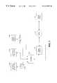
- Three different configurationsare illustrated in FIG. 1 for communicating light sensor data from an ATM device to a central system 118 . Each of these embodiments will be discussed in more detail in connection with FIGS. 2, 3 , and 4 A.
- a plurality of sensors 130are disposed in communication with an ATM 120 .
- the sensorsinclude light level sensors, and may include additional sensors such as sensors for detecting the proper operation of a security camera disposed in connection with the ATM 120 .
- a cellular transmitter 102is also disposed in connection with the ATM 120 .
- the sensor status informationis provided to the cellular transmitter, which establishes a communication link via cell site 104 , MTSO 106 , and PSTN 116 to a central system 118 .
- the central system 118may include dispatch personnel, which could respond to a condition of low lighting detected by the sensors 130 at the ATM 120 to repair or correct any defective condition sensed.
- the sensors 130may be configured to, in essence, report a binary state.
- the sensors 130may be configured to quantify and report a precise level of lighting detected at the sensors 130 . This information could be monitored at the central system, and if lighting conditions were detected to be on the decline, then the central system 1 18 could dispatch a service person to check on or service the lighting system at ATM 120 .
- a plurality of sensors 132are disposed in connection with an ATM 122 .
- This embodimentmay be configured similar to the first embodiment, with the exception that the second embodiment does not utilize a cellular transmitter.
- an RF transmitter 126may be configured in place of the cellular transmitter 102 .
- the RF transmitter 126may be configured to communicate data via an RF link to a remote (but nearby) receiver 129 .
- the receiver 129may be disposed in connection with a phone line interface to further communicate the received data across a land-line telephone (i. e., PSTN 116 ) to the central system 118 .
- a land-line telephonei. e., PSTN 116
- sensors 134may be disposed in connection with an ATM 124 , as in the first two embodiments.
- a phone interface 128is provided within the ATM 124 .
- the phone interface 128provides a direct interface in connection to a land-line telephone (i.e., the PSTN 116 ) for communication of data directly via the PSTN 116 to the central system 118 .
- FIG. 1Each of the embodiments briefly described above will be described in more detail in connection with FIGS. 2, 3 , and 4 A. It will be appreciated, however, that further variations of these systems may be provided consistent with the present invention. Furthermore, the various embodiments may be collectively configured (as shown in FIG. 1) in a single system, which monitors a plurality of ATMs 120 , 122 , and 124 . It will be appreciated that the invention provides a robust and economical system for monitoring light levels surrounding automatic teller machines 120 , 122 , and 124 , whereby upon detection of below specified lighting conditions, service and repair personnel may dispatched immediately to rectify the situation. In this way, lighting provided at various banking facilities may be maintained at safe operating levels, thereby minimizing theft, which may otherwise occur around these banking machines.
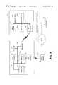
- FIG. 2shows the first embodiment in more detail.
- the ATM environmentis illustrated as having a plurality of sensors 130 a , 130 b , and 130 c . More specifically, a plurality of light level sensors or transceivers 130 a and 130 b are disposed in communication with a computer 121 . Although only two light level sensors 130 a and 130 b have been illustrated, it will be appreciated that many more may be provided consistent with the concepts of the invention. Similarly, additional security camera sensors 130 c , or other operational sensors may be provided.
- the computer 121for purposes of this application, broadly refers to any processing device, such as an electronic circuit including a microprocessor, microcontroller, a specially configured state machine, or other electronic circuit that is configured to process a sequence of instructions.
- a camera sensor 130 cis also disposed in communication with the computer 121 .
- the sensors 130 a , 130 b , and 130 cmay be passive components configured to sense a level of light (or operability of a camera) and report that data to the computer 121 via a direct wire connection.
- the computer 121may have an interface (not shown) that reads the values on the various signal connections 152 , 154 , and 156 .
- the signal connections 152 , 154 , and 156may be single wire connections that convey binary information (i.e., logic high or logic low) to reflect whether or not the lighting condition detected by the light sensors 130 a and 130 b exceeds any lighting specifications.
- the signal line 156may be a binary signal simply indicating whether the camera monitored by the sensor 130 c is operable.
- the signal connections 152 , 154 , and 156may be single wire connections that convey analog information that is received at the ATM 120 by an interface (not shown) that converts the analog values carried on the signal lines into digital values that may be read and processed by the computer 121 .
- Analog signalsmay convey a spectrum of information, most notably an accurate reading of a precise light level sensed by the sensors 130 a and 130 b.
- the sensors 130 a , 130 b , and 130 cmay comprise transceivers that are capable of either transmitting information to the computer 121 or receiving information from the computer 121 .
- the signal connections 152 , 154 , and 156may comprise a serial interface, a parallel interface, or other interface to appropriately interconnect the sensors 130 a , 130 b , and 130 c with the computer 121 .
- the computer 121may periodically request the status of the sensors 130 a , 130 b , and 130 c . This request/response protocol is illustrated in the figure by the designations Ping (computer request for information) and Pong (sensor's response to the request).
- the computer 121may periodically request this information on its own initiative and timing, or may be further responding to requests ultimately made by the central system 118 .
- the central system 118may initiate a request for information about the lighting in a particular ATM 120 , whereby this request is initiated over the PSTN 116 and is routed through the MTSO 106 .
- the MTSO 106may then initiate a call via a cellular link to the cellular transceiver 102 within the ATM 120 .
- the cellular transceiver 102may then relay this request to the computer 121 which then submits individual requests to the sensors for information.
- the response (Pong)may then be relayed back through the various links to the central system.
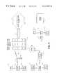
- FIG. 3shows an alternative environment for the present invention.
- sensors 134 A, 134 B, and 134 care provided in connection with an AtM 124 .
- the sensors 134 A, 134 B, and 134 c , and their communication with the computer 161may be the same as that described in connection with sensors 130 a , 130 b , and 130 c , in computer 121 of FIG. 2, and need not be further described herein.
- the significant distinction between the environment of FIG. 2 and that of FIG. 3is that the environment of FIG. 3 communicates directly from the ATM 124 across the PSTN 116 to the central system 118 , whereas the environment of FIG. 2 communicate via a cellular link before reaching the PSTN 116 .
- a phone interface 128is provided in connection with the computer 161 at the ATM 124 .
- This phone interfaceis designed to interface directly with a telephone line, and thus communicate across the PSTN 116 . It is anticipated that this environment will be the most common environment for ATM devices that are provided in connection with a banking facility, and are therefore not subject to move. However, other ATM devices are provided in shopping malls, at restaurants, in grocery stores, and a variety of other facilities where the routing of a telephone line directly to the ATM may not be desirable. In such an environment, the embodiment of FIG. 2 or that of FIG. 4A (which will be discussed below) may be more desirable.
- FIG. 4Ashows yet another environment for the present invention.
- sensors 132 a , 132 b , and 132 care disposed in communication with a computer 171 . Operation of the sensors 132 a , 132 b , and 132 c and a computer 171 will be as described in connection with FIG. 2, and therefore need not be repeated here.
- the significant difference of the environment of FIG. 4Ais that an RF transmitter 126 is provided at the ATM 122 for communicating data to the central system 118 .
- the transmitter 126is a relatively low power RF transmitter that communicates data via an RF link to a nearby receiver 129 that is disposed in connection with a telephone interface, for connection to a telephone line and therefore communication via the PSTN 116 .
- the RF communication device 126may be a transceiver capable of bi-directional communication via RF link 173 with a transceiver disposed in communication with a phone interface. This would allow requests from the central system 118 to be made across the PSTN 116 and through the transceiver 126 for status information of the various sensors 132 a , 132 b , and 132 c.
- FIG. 4Bdescribes the communication of data between the transmitter 126 and the receiver/telephone interface 129 . Again, this transmission of data occurs across an RF link 173 .
- the receiver/telephone interface 129is disposed internally and in connection with a public, pay-type telephone 180 .
- the particular format and protocol of data transmitted from the transmitter 126may be as described in co-pending U.S. patent application Ser. No. 09/102,178, filed on Jun. 22, 1998.
- the packet of data communicated across the RF link 173may include certain synchronization bits, certain error detection and correction bits, and an encoded data word.
- the encoded data wordwill preferably convey the status of all the sensors 132 a , 132 b , and 132 c a the ATM location.
- a computer at the central system 118may be configured to decode the encoded data word to ascertain the precise value and status of each of the various sensors.
- FIG. 5is a flow chart that illustrates the top level operation of a system constructed in accordance with the present invention.
- the systemcontinually monitors light sensors which are configured to detect either a quantization of lighting at a particular location around an ATM device, or, alternatively, to detect whether or not the lighting conditions at a given location exceed certain specified threshold values (step 190 ).
- the status of the light sensorsis then communicated to the ATM (step 192 ).
- the ATMthen communicates this sensor status to a central system (step 194 ).
- this communication stepmay comprise communication across a cellular link, direct line communication from a telephone interface provided at the ATM, or alternatively an intermediate communication via an RF link to a nearby receiver that then further communicates the data via the PSTN to a central system. If the central system deems that the light level sensed at the various lighting sensors is adequate (i.e., meets or exceeds specification) then it returns to step 190 where it continues the monitoring of a light level sensors. If, however, the central system determines that the light level at the various lighting sensors is inadequate or below specifications, then it may dispatch service personnel to correct the faulted lighted conditions to bring the lighting around the ATM device back up to the specifications, and therefore reduce the possibility of theft or other crime at the ATM site.
- the ATM deviceis not a limitation on the invention, but simply defines an environment for the preferred embodiment. Accordingly, the concepts and teachings of the invention as described above may be realized in an identical system surrounding some device other than an ATM. It has been illustrated as being disposed within an ATM device purely as a matter of convenience, and should not be viewed as limiting on the invention. Accordingly, additional alternative embodiments of the present invention are set forth in FIGS. 6, 7 , and 8 . Further, in these additional embodiments, it has been chosen to illustrate the light sensor units in a differing fashion.
- each light meter gaugeincludes a light sensor 202 a (preferably a photo-cell), a processing unit 204 a , a memory 206 a , and an RF transmitter 208 a .
- the processing unit 204 amay be a microprocessor, a microcontroller, or other circuitry configured to control the operation of the light meter gauge 230 a , or otherwise execute a sequence of instructions or operations.
- the photo-cell 202 ais a component that reacts to the intensity of light to generate an output electrical signal that may be supplied to the other components of the light meter gauge.
- a bus 227 ahas been illustrated in FIG. 6 as providing a communication link between the various devices on the light meter gauge 230 a . It will be appreciated that, in practice, there will be a number of electrical signal wires interconnecting these devices, including conductors that make up a data bus, an address bus, and a variety of control and signaling conductors as well. Further, it will be appreciated that the output of the photo-cell 202 a will typically be an analog value.
- an analog to digital converter(not shown) would necessarily be included in the preferred embodiment in order to convert the analog data value output from the photo-cell 202 a into a format suitable to be read by the microprocessor 204 a and/or written to memory 206 a .
- Each light meter gauge 230 a and 230 bcan be configured by storing a program in memory 206 a , 206 b that controls the operation of the microprocessor 204 a , 204 b.
- each of the light meter gauges 230 a and 230 brelates to the RF transmitter 208 a and 208 b .
- These transmittersare the mechanisms through which each of the plurality of light meter gauges 230 a and 230 b intercommunicate.
- FIG. 6has been illustrated with just two light meter gauges 230 a and 230 b , it will be appreciated that, consistent with the concepts in teachings of the present invention, additional light meter gauges may be provided.
- a first light meter gauge 230 awill be configured as a master unit. This configuration may be defined by the program set up in memory 206 a to control microprocessor 204 a .
- each light meter gaugemay be configured with a unique identification code that allows the master unit to poll each individual slave device (using the identification codes as addresses) for its current operational status; namely, the status of the photo-cell 202 output.
- each of the slave light meter gaugesmay be configured to communicate by a different RF frequency, and the master light meter gauge may be configured to poll across the various frequencies in order to ascertain the status of the individual slave devices.
- the detailed implementation regarding the communication between the master unit and the various slave devicesmay be carried out in a variety of ways.
- the master light meter gauge 230 ais configured with a telecommunications interface.
- the telecommunications interfaceis a PSTN interface 210 that allows the master light meter gauge 230 a to communicate with the PSTN 116 via, for example, a standard telephone line hookup.
- the master light meter gauge 230 acollects the data from the various slave light meter gauges and relays that information to the central system 218 via the telecommunications interface. This relay of information may be implemented in a variety of manners.
- the master unitmay periodically relay status information of all of the light meter gauges 230 a and 230 b .
- each light meter gaugemay be configured with a unique identification code 219 a and 219 b , which may be read by the microprocessor 204 a and 204 b for communication via the RF transmitters 208 b of the various slave light meter gauges to the RF transmitter 208 a of the master light meter gauge.
- each data packetmay include an identification code of each light meter gauge along with a data value associated with each identification code.
- the associated data valuesmay reflect the status of the light meter gauge 230 a and 230 b , including the intensity value output from the photo-cell 202 a and 202 b .
- the master light meter gauge 230 amay be configured to dial up the central system 218 and send out a short packet of data.
- This short packet of datamay simply be a command that indicates a “ok” or an “all clear” message that informs the central system 218 that all light meter gauges at the given location defined by the master unit are in proper working order, and are receiving light at or above a specified intensity level, and therefore no service needs are required. If, however, the light intensity received at any light meter gauge falls below the specified level, then the master unit may configure the message packet to identify the specific light meter gauge (by its identification code) that is below specification, and/or its illumination level.
- a computer system 220may be provided to automatically receive incoming calls from the master light meter gauge 230 a and interpret the data packet to respond in an automated fashion.
- FIG. 6illustrates various factors or data fields or objects that the computer 220 may utilize during operation. Items like a time/date stamp, a location identification, a light meter identification, personnel contact, and other data values or objects may be maintained in records at the central system 218 .
- the location identificationmay identify a given area that is monitored by a plurality of light meter gauges.
- the light meter identificationmay be a data value that identifies an identification code for specific light meter gauges at a given location.
- An illumination meter data valuemay simply be the status value (i.e., photo-cell intensity value) that is associated with a given light meter gauge identification code. As previously mentioned, this value may represent the intensity of light incident upon a particular light meter gauge. This value may be compared against a time/date stamp to determine whether, at any given time, the light meter intensity meets or exceeds a predefined threshold value. Also, a personnel contact data field may be provided. Assuming the central station 218 monitors or receives status information from a variety of monitoring systems dispersed at different geographic regions, the personnel contact may differ.
- a failureis detected in a light metering system at a first location, then a first personnel contact may be identified, whereas if a different light metering system failure at a geographically distinct location, a second personnel contact (i.e., service person) may be identified.
- a second personnel contacti.e., service person
- a third service personnelmay be contacted.
- the computer 220may be configured to automatically prompt the service personnel as by e-mail, paging, or otherwise to notify them of the problem and the location of the problem to be corrected.
- the telecommunications interfaceis a cellular transmitter 230 .
- the cellular transmittermay include a modem and therefore communicate via cellular modem link.
- the cellular link provided by interface 230communicates via cell site 204 and MTSO 106 in a manner similar to that described in connection with FIG. 1 .
- the various other aspects of FIG. 7may be configured as described in connection with FIG. 6 .
- FIG. 8shows yet another embodiment of the present invention similar to those of FIGS. 6 and 7. Indeed, the embodiment illustrated may be viewed as operating in the same fashion as that described above, with the exception that the telecommunications interface is an RF interface 240 .
- the master light gauge 230 amay communicate via RF telecommunications link to a nearby RF receiver 129 , which includes a PSTN interface for communication with the PSTN 116 .
- the RF receivermay be a RF receiver that is disposed in a nearby pay-type telephone.
- FIG. 9illustrates an embodiment similar to FIG. 1, but reflecting the embodiments of FIGS. 6, 7 , and 8 . Therefore, an overall system may comprise a variety of configurations of master/slave gauges depending upon the location being reported from. Therefore, a first master gauge 302 may be provided to communicate with a plurality of slave gauges 304 and 306 via RF transmission links as described above. This first master gauge 302 may be configured to communicate with a central system 118 via a cellular link 305 to a cell site 104 , MTSO 106 , and PSTN 116 .
- a second master gauge 308may be configured to communicate with a plurality of slave gauges 310 and 312 and communicate via RF link 313 to a nearby RF receiver 129 which is interfaced to a standard PSTN telephone line.
- a master gauge 314may be configured to communicate via RF links with a plurality of slave gauges 316 and 318 , wherein the master gauge 314 includes a PSTN interface 320 to communicate via the PSTN 116 to the central system 118 .
- the light meter gaugesmay be constructed in a physically similar manner. That is, from a mass-manufactured standpoint, all of the light meter gauges 230 a and 230 b may be designed to include the telecommunications interface (e.g., cellular transmitter, PSTN interface, RF interface, etc.). However, upon configuration, one of these units may be configured to utilize that interface as a master unit, while the remaining units are configured to operate as slave devices, and therefore not use the interface. It will be appreciated, of course, that this is purely a matter of design choice and economy in manufacture.
- the telecommunications interfacee.g., cellular transmitter, PSTN interface, RF interface, etc.
- the master light meter gaugemay include an onboard clock, whereby it may compare the magnitude of the output from the light sensor (photo-cell) to a given time of day reading, to determine whether the unit is receiving an adequate amount of light.
- the master unitmay be configured simply to periodically transmit this data to the central system, which may be configured to maintain a centralized clock/time of day device.
- embodiments of the present inventionmay incorporate a customer access feature so that a customer 402 may be provided with information regarding the lighted ATM area, such as via the Internet 403 , among others.
- the embodiment depicted in FIG. 10allows information from the various sensors to be communicated to the central system 118 via PSTN 116 .
- the central system 118is configured to provide the information to a database which is accessible to the customer, preferably through a web site.
- the central system 118may include a computer that monitors an Internet connection. So configured, customers may access information corresponding to the various sensors by accessing the web site hosted by the central system.
- a selected techniciansuch as technician 404
- the notificationmay be accomplished via an e-mail message, for instance, and may consist of the location of the light gauges, the light level reading of the light gauges, and an identification code corresponding to the light gauges, among others.
- the selection of the technicianmay be selected based on numerous criteria, including whether the technician has a repair contract in place for servicing the customer's ATMs, or whether the technician services the local area in which the customer's ATM resides, among others.
- the customermay be provided with an alert message.
- the alert messagealso may include specific information corresponding to the ATM, such as the location of the light gauges, the light level reading of the light gauges, and an identification code corresponding to the light gauges, among others.
- video images produced by the camerasalso may be provided to the customer via the Internet web site.
- the customer access featureis provided by a customer-access monitoring system which can be implemented in hardware, software, firmware, or a combination thereof.
- a customer-access monitoring systemwhich can be implemented in hardware, software, firmware, or a combination thereof.
- the customer-access monitoring systemis implemented as a software package, which can be adaptable to run on different platforms and operating systems as shall be described further herein.
- a preferred embodiment of the customer-access monitoring systemwhich comprises an ordered listing of executable instructions for implementing logical functions, can be embodied in any computer-readable medium for use by or in connection with an instruction execution system, apparatus, or device, such as a computer-based system, processor-containing system, or other system that can fetch the instructions from the instruction execution system, apparatus, or device, and execute the instructions.
- a “computer-readable medium”can be any means that can contain, store, communicate, propagate or transport the program for use by or in connection with the instruction execution system, apparatus, or device.
- the computer readable mediumcan be, for example, but not limited to, an electronic, magnetic, optical, electro-magnetic, infrared, or semi-conductor system, apparatus, device, or propagation medium. More specific examples (a nonexhaustive list) of the computer-readable medium would include the following: an electrical connection (electronic) having one or more wires, a portable computer diskette (magnetic), a random access memory (RAM) (magnetic), a read-only memory (ROM) (magnetic), an erasable, programmable, read-only memory (EPROM or Flash memory) (magnetic), an optical fiber (optical), and a portable compact disk read-only memory (CDROM) (optical).
- an electrical connectionelectronic having one or more wires
- a portable computer diskettemagnetic
- RAMrandom access memory
- ROMread-only memory
- EPROM or Flash memoryerasable, programmable, read-only memory
- CDROMportable compact disk read-only memory
- the computer-readable mediumcould even be paper or another suitable medium upon which the program is printed, as the program can be electronically captured, via for instance, optical scanning of the paper or other medium, then compiled, interpreted, or otherwise processed in a suitable manner, if necessary, and then stored in a computer memory.
- FIG. 11illustrates a typical computer or processor-based system 406 which may utilize the customer-access monitoring system 408 .
- a computer system 406generally comprises a processor 410 and a memory 412 with an operating system 414 .
- the memory 412may be any combination of volatile and nonvolatile memory elements, such as random access memory or read only memory.
- the processor 410accepts instructions and data from memory 412 over a local interface 416 , such as a bus(es).
- the systemalso includes an input device(s) 418 and an output device(s) 420 . Examples of input devices may include, but are not limited to a serial port, a scanner, or a local access network connection.
- Examples of output devicesmay include, but are not limited to, a video display, a Universal Serial Bus, or a printer port.
- this systemmay run any of a number of different platforms and operating systems, including, but not limited to, Windows NTTM, UnixTM, or Sun SolarisTM operating systems.
- the customer accessible monitoring system of the present inventionresides in memory 412 and is executed by the processor 410 .
- the customer-access monitoring system 408can be adapted to provide a customer with access to ATM status information.
- customer 402may access ATM status information by accessing a web site established by the central system 118 via the Internet 403 , as previously described.
- Information provided at the web siteis controlled by the central system 118 and typically is stored in a database 422 which is accessed by the monitoring system 408 of the central system computer 406 .
- ATM status informationmay be provided to technician 404 , such as in the form of a notification message, as previously described, via the Internet 403 .
- the customer-access monitoring system 408also can be adapted to provide a customer with direct access to ATM status information. Embodiments of the present invention so adapted may effectively remove the central system 118 from the monitoring process and may be preferred depending upon the particular application.
- customer 424is able to communicate directly with various ATMs via the PSTN 116 , thus allowing the customer to query the various ATMs regarding status information.
- the monitoring system 408has been installed on the customer's computer systems 406 , the monitoring system allows the customer 424 to access ATM information by communicating directly with the ATMs.
- the customermay make status queries which are communicated to the ATMs, such as to the CPUs of the respective ATMs.
- the CPUSsuch as the CPUs of a master gauges, for instance, provide the requested information directly to the customer.
- the monitoring systemmay be established to receive periodic updates of status information from the ATMs, thereby allowing a customer to receive the most recent status information communicated to the monitoring system without the necessity of a customer-prompted query.
- the monitoring systemalso may incorporate an auto-alert feature, whereby the monitoring system informs the customer via a prompt or other suitable alarm that a failure condition at a monitored site has occurred. Additionally, the monitoring system may forward a notification message to a technician, as previously described.
- the customer-access monitoring system 408can be adapted to provide technicians with direct access to ATM status information.
- technician 430is able to communicate directly with various ATMs via the PSTN 116 , thus allowing the technician to query the various ATMs regarding status information.
- some embodimentsmay allow a customer to receive status information through network 428 (i.e., a LAN), whereby the central system maintains the information in a database as previously described, and then allows the customer, such as customer 432 , to access the information stored in the database via the network.
- network 428i.e., a LAN
- technician 434also may access or receive information relating to the ATMs.
Landscapes
- Business, Economics & Management (AREA)
- Accounting & Taxation (AREA)
- Physics & Mathematics (AREA)
- General Physics & Mathematics (AREA)
- Finance (AREA)
- Emergency Management (AREA)
- Telephonic Communication Services (AREA)
Abstract
Description
Claims (19)
Priority Applications (29)
| Application Number | Priority Date | Filing Date | Title |
|---|---|---|---|
| US09/412,895US6218953B1 (en) | 1998-10-14 | 1999-10-05 | System and method for monitoring the light level around an ATM |
| US09/439,059US6437692B1 (en) | 1998-06-22 | 1999-11-12 | System and method for monitoring and controlling remote devices |
| US09/704,150US6891838B1 (en) | 1998-06-22 | 2000-11-01 | System and method for monitoring and controlling residential devices |
| US09/811,076US6914533B2 (en) | 1998-06-22 | 2001-03-16 | System and method for accessing residential monitoring devices |
| US09/812,044US6914893B2 (en) | 1998-06-22 | 2001-03-19 | System and method for monitoring and controlling remote devices |
| US09/812,809US20020013679A1 (en) | 1998-10-14 | 2001-03-20 | System and method for monitoring the light level in a lighted area |
| US09/925,269US7103511B2 (en) | 1998-10-14 | 2001-08-09 | Wireless communication networks for providing remote monitoring of devices |
| US09/925,786US7650425B2 (en) | 1999-03-18 | 2001-08-09 | System and method for controlling communication between a host computer and communication devices associated with remote devices in an automated monitoring system |
| US10/139,492US7053767B2 (en) | 1998-06-22 | 2002-05-06 | System and method for monitoring and controlling remote devices |
| US11/119,054US7295128B2 (en) | 1998-06-22 | 2005-04-29 | Smoke detection methods, devices, and systems |
| US11/125,009US8064412B2 (en) | 1998-06-22 | 2005-05-09 | Systems and methods for monitoring conditions |
| US11/159,768US7697492B2 (en) | 1998-06-22 | 2005-06-23 | Systems and methods for monitoring and controlling remote devices |
| US11/395,685US7468661B2 (en) | 1998-06-22 | 2006-03-31 | System and method for monitoring and controlling remote devices |
| US12/337,739US7978059B2 (en) | 1998-06-22 | 2008-12-18 | System and method for monitoring and controlling remote devices |
| US12/477,329US8013732B2 (en) | 1998-06-22 | 2009-06-03 | Systems and methods for monitoring and controlling remote devices |
| US12/689,220US8930571B2 (en) | 1999-03-18 | 2010-01-18 | Systems and methods for controlling communication between a host computer and communication devices |
| US12/758,590US8964708B2 (en) | 1998-06-22 | 2010-04-12 | Systems and methods for monitoring and controlling remote devices |
| US13/173,499US8212667B2 (en) | 1998-06-22 | 2011-06-30 | Automotive diagnostic data monitoring systems and methods |
| US13/221,689US8223010B2 (en) | 1998-06-22 | 2011-08-30 | Systems and methods for monitoring vehicle parking |
| US13/222,216US8410931B2 (en) | 1998-06-22 | 2011-08-31 | Mobile inventory unit monitoring systems and methods |
| US13/225,110US8193930B2 (en) | 1998-06-22 | 2011-09-02 | Systems and methods for remote irrigation control |
| US13/333,967US9129497B2 (en) | 1998-06-22 | 2011-12-21 | Systems and methods for monitoring conditions |
| US13/485,977US8924587B2 (en) | 1999-03-18 | 2012-06-01 | Systems and methods for controlling communication between a host computer and communication devices |
| US13/486,014US8924588B2 (en) | 1999-03-18 | 2012-06-01 | Systems and methods for controlling communication between a host computer and communication devices |
| US13/855,452US8754780B2 (en) | 1998-06-22 | 2013-04-02 | Systems and methods for monitoring and controlling remote devices |
| US14/306,412US9571582B2 (en) | 1998-06-22 | 2014-06-17 | Systems and methods for monitoring and controlling remote devices |
| US14/590,353US20150127824A1 (en) | 1999-03-18 | 2015-01-06 | Systems and methods for controlling communication between a host computer and communication devices |
| US14/629,912US9430936B2 (en) | 1998-06-22 | 2015-02-24 | Systems and methods for monitoring and controlling remote devices |
| US14/836,226US9691263B2 (en) | 1998-06-22 | 2015-08-26 | Systems and methods for monitoring conditions |
Applications Claiming Priority (2)
| Application Number | Priority Date | Filing Date | Title |
|---|---|---|---|
| US09/172,554US6028522A (en) | 1998-10-14 | 1998-10-14 | System for monitoring the light level around an ATM |
| US09/412,895US6218953B1 (en) | 1998-10-14 | 1999-10-05 | System and method for monitoring the light level around an ATM |
Related Parent Applications (3)
| Application Number | Title | Priority Date | Filing Date |
|---|---|---|---|
| US09/172,554Continuation-In-PartUS6028522A (en) | 1998-06-22 | 1998-10-14 | System for monitoring the light level around an ATM |
| US27151799AContinuation-In-Part | 1998-06-22 | 1999-03-18 | |
| US09/439,059Continuation-In-PartUS6437692B1 (en) | 1998-06-22 | 1999-11-12 | System and method for monitoring and controlling remote devices |
Related Child Applications (8)
| Application Number | Title | Priority Date | Filing Date |
|---|---|---|---|
| US09/102,178Continuation-In-PartUS6430268B1 (en) | 1997-02-14 | 1998-06-22 | Systems for requesting service of a vending machine |
| US09/172,554Continuation-In-PartUS6028522A (en) | 1998-06-22 | 1998-10-14 | System for monitoring the light level around an ATM |
| US27151799AContinuation-In-Part | 1998-06-22 | 1999-03-18 | |
| US09/439,059Continuation-In-PartUS6437692B1 (en) | 1998-06-22 | 1999-11-12 | System and method for monitoring and controlling remote devices |
| US09/704,150Continuation-In-PartUS6891838B1 (en) | 1998-06-22 | 2000-11-01 | System and method for monitoring and controlling residential devices |
| US09/811,076Continuation-In-PartUS6914533B2 (en) | 1998-06-22 | 2001-03-16 | System and method for accessing residential monitoring devices |
| US09/812,044Continuation-In-PartUS6914893B2 (en) | 1998-06-22 | 2001-03-19 | System and method for monitoring and controlling remote devices |
| US09/812,809Continuation-In-PartUS20020013679A1 (en) | 1998-10-14 | 2001-03-20 | System and method for monitoring the light level in a lighted area |
Publications (1)
| Publication Number | Publication Date |
|---|---|
| US6218953B1true US6218953B1 (en) | 2001-04-17 |
Family
ID=26868207
Family Applications (1)
| Application Number | Title | Priority Date | Filing Date |
|---|---|---|---|
| US09/412,895Expired - LifetimeUS6218953B1 (en) | 1998-06-22 | 1999-10-05 | System and method for monitoring the light level around an ATM |
Country Status (1)
| Country | Link |
|---|---|
| US (1) | US6218953B1 (en) |
Cited By (156)
| Publication number | Priority date | Publication date | Assignee | Title |
|---|---|---|---|---|
| US20020019725A1 (en)* | 1998-10-14 | 2002-02-14 | Statsignal Systems, Inc. | Wireless communication networks for providing remote monitoring of devices |
| US20020027504A1 (en)* | 1999-03-18 | 2002-03-07 | James Davis | System and method for controlling communication between a host computer and communication devices associated with remote devices in an automated monitoring system |
| US20020103897A1 (en)* | 2000-09-06 | 2002-08-01 | Babak Rezvani | Method and system for adaptively setting a data refresh interval |
| US20020125998A1 (en)* | 1998-06-22 | 2002-09-12 | Petite Thomas D. | System and method for monitoring and controlling remote devices |
| GB2381111A (en)* | 2001-10-20 | 2003-04-23 | Ncr Int Inc | Method of providing information for maintenance of remote terminals |
| US20030135547A1 (en)* | 2001-07-23 | 2003-07-17 | Kent J. Thomas | Extensible modular communication executive with active message queue and intelligent message pre-validation |
| US20030140090A1 (en)* | 2000-09-06 | 2003-07-24 | Babak Rezvani | Automated upload of content based on captured event |
| US6621827B1 (en)* | 2000-09-06 | 2003-09-16 | Xanboo, Inc. | Adaptive method for polling |
| US20030213161A1 (en)* | 2002-03-29 | 2003-11-20 | Gardner James P. | Method and apparatus for automatic pest trap report generation and additional trap parameter data |
| US6686838B1 (en) | 2000-09-06 | 2004-02-03 | Xanboo Inc. | Systems and methods for the automatic registration of devices |
| US6717660B1 (en)* | 2000-08-01 | 2004-04-06 | Safe Passage Systems Corporation | System for monitoring and testing of light sources |
| US6747981B2 (en) | 1997-02-12 | 2004-06-08 | Elster Electricity, Llc | Remote access to electronic meters using a TCP/IP protocol suite |
| US20040119587A1 (en)* | 2002-12-19 | 2004-06-24 | David Davenport | Method and apparatus for monitoring and controlling warning systems |
| US20050043059A1 (en)* | 2000-08-09 | 2005-02-24 | Petite Thomas D. | Systems and methods for providing remote monitoring of electricity consumption for an electric meter |
| US20050055432A1 (en)* | 2003-09-08 | 2005-03-10 | Smart Synch, Inc. | Systems and methods for remote power management using 802.11 wireless protocols |
| US20050065742A1 (en)* | 2003-09-08 | 2005-03-24 | Smartsynch, Inc. | Systems and methods for remote power management using IEEE 802 based wireless communication links |
| US20050073584A1 (en)* | 1998-10-09 | 2005-04-07 | Diebold, Incorporated | Cash dispensing automated banking machine with improved fraud detection capabilities |
| US20050083210A1 (en)* | 2002-06-27 | 2005-04-21 | Shuey Kenneth C. | Dynamic self-configuring metering network |
| US20050172024A1 (en)* | 2004-01-26 | 2005-08-04 | Tantalus Systems Corp. | Communications system |
| US20050239414A1 (en)* | 2004-04-26 | 2005-10-27 | Mason Robert T Jr | Method and system for configurable qualification and registration in a fixed network automated meter reading system |
| US20050237221A1 (en)* | 2004-04-26 | 2005-10-27 | Brian Brent R | System and method for improved transmission of meter data |
| US20050278440A1 (en)* | 2004-06-15 | 2005-12-15 | Elster Electricity, Llc. | System and method of visualizing network layout and performance characteristics in a wireless network |
| US20060056423A1 (en)* | 2004-09-10 | 2006-03-16 | Ovidiu Ratiu | System and method for communicating messages in a mesh network |
| US20060056331A1 (en)* | 2004-09-10 | 2006-03-16 | Ovidiu Ratiu | System and method for communicating broadcast messages in a mesh network |
| US20060056363A1 (en)* | 2004-09-10 | 2006-03-16 | Ovidiu Ratiu | System and method for a wireless mesh network |
| US20060056456A1 (en)* | 2004-09-10 | 2006-03-16 | Ovidiu Ratiu | System and method for message consolidation in a mesh network |
| US20060055529A1 (en)* | 2004-09-10 | 2006-03-16 | Ovidiu Ratiu | System and method for communicating alarm conditions in a mesh network |
| US20060071810A1 (en)* | 2004-09-24 | 2006-04-06 | Elster Electricity, Llc. | System for automatically enforcing a demand reset in a fixed network of electricity meters |
| US20060085535A1 (en)* | 2004-08-09 | 2006-04-20 | Tetsuro Motoyama | System and method to integrate device, user, and account information |
| US20060104312A1 (en)* | 2004-11-16 | 2006-05-18 | SONITROL CORPORATION, Corporation of the State of Delaware | System and method for monitoring security at a premises |
| US7075429B2 (en) | 2004-10-14 | 2006-07-11 | Cranbrook Marshall | Alarm with remote monitor and delay timer |
| US7079810B2 (en) | 1997-02-14 | 2006-07-18 | Statsignal Ipc, Llc | System and method for communicating with a remote communication unit via the public switched telephone network (PSTN) |
| US20060165044A1 (en)* | 2004-12-03 | 2006-07-27 | Advanced Metering Data Systems, L.L.C. | Method, system, apparatus, and computer program product for communications relay |
| US7137550B1 (en) | 1997-02-14 | 2006-11-21 | Statsignal Ipc, Llc | Transmitter for accessing automated financial transaction machines |
| US7170425B2 (en) | 2004-09-24 | 2007-01-30 | Elster Electricity, Llc | System and method for creating multiple operating territories within a meter reading system |
| US20070156253A1 (en)* | 2006-01-03 | 2007-07-05 | Industrial Telemetry, Inc. | Apparatus and method for wireless process control |
| US20070179754A1 (en)* | 2006-01-30 | 2007-08-02 | Sper Scientific Ltd. | Wireless meter for real time measurements and method therefor |
| US7263073B2 (en) | 1999-03-18 | 2007-08-28 | Statsignal Ipc, Llc | Systems and methods for enabling a mobile user to notify an automated monitoring system of an emergency situation |
| US7262709B2 (en) | 2004-04-26 | 2007-08-28 | Elster Electricity, Llc | System and method for efficient configuration in a fixed network automated meter reading system |
| US7295128B2 (en) | 1998-06-22 | 2007-11-13 | Sipco, Llc | Smoke detection methods, devices, and systems |
| US7308370B2 (en) | 2005-03-22 | 2007-12-11 | Elster Electricity Llc | Using a fixed network wireless data collection system to improve utility responsiveness to power outages |
| US7308369B2 (en) | 2005-09-28 | 2007-12-11 | Elster Electricity Llc | Ensuring automatic season change demand resets in a mesh type network of telemetry devices |
| US7312721B2 (en) | 2002-06-28 | 2007-12-25 | Elster Electricity, Llc | Data collector for an automated meter reading system |
| US7327998B2 (en) | 2004-12-22 | 2008-02-05 | Elster Electricity, Llc | System and method of providing a geographic view of nodes in a wireless network |
| US7346463B2 (en) | 2001-08-09 | 2008-03-18 | Hunt Technologies, Llc | System for controlling electrically-powered devices in an electrical network |
| US20080069013A1 (en)* | 2006-09-15 | 2008-03-20 | Fabrice Monier | Beacon requests and RS bit resolving circular routes |
| US20080068215A1 (en)* | 2006-09-15 | 2008-03-20 | Stuber Michael T G | Home area networking (HAN) with low power considerations for battery devices |
| US20080092132A1 (en)* | 2006-08-31 | 2008-04-17 | Stuber Michael T G | Firmware download |
| US20080094248A1 (en)* | 2006-10-19 | 2008-04-24 | Lakich Daniel M | Extending contact life in remote disconnect applications |
| US20080132185A1 (en)* | 2002-01-02 | 2008-06-05 | Elliott Karl E | Wireless communication enabled meter and network |
| US7397907B2 (en) | 1997-02-14 | 2008-07-08 | Sipco, Llc | Multi-function general purpose transceiver |
| US20080186898A1 (en)* | 2005-01-25 | 2008-08-07 | Sipco, Llc | Wireless Network Protocol System And Methods |
| US7424527B2 (en) | 2001-10-30 | 2008-09-09 | Sipco, Llc | System and method for transmitting pollution information over an integrated wireless network |
| US7427927B2 (en) | 2006-02-16 | 2008-09-23 | Elster Electricity, Llc | In-home display communicates with a fixed network meter reading system |
| US20080274766A1 (en)* | 2007-04-13 | 2008-11-06 | Hart Communication Foundation | Combined Wired and Wireless Communications with Field Devices in a Process Control Environment |
| US20080273486A1 (en)* | 2007-04-13 | 2008-11-06 | Hart Communication Foundation | Wireless Protocol Adapter |
| US20080279155A1 (en)* | 2007-04-13 | 2008-11-13 | Hart Communication Foundation | Adaptive Scheduling in a Wireless Network |
| US20090010203A1 (en)* | 2007-04-13 | 2009-01-08 | Hart Communication Foundation | Efficient Addressing in Wireless Hart Protocol |
| US7480501B2 (en) | 2001-10-24 | 2009-01-20 | Statsignal Ipc, Llc | System and method for transmitting an emergency message over an integrated wireless network |
| US20090046675A1 (en)* | 2007-04-13 | 2009-02-19 | Hart Communication Foundation | Scheduling Communication Frames in a Wireless Network |
| US7495578B2 (en) | 2005-09-02 | 2009-02-24 | Elster Electricity, Llc | Multipurpose interface for an automated meter reading device |
| US20090059814A1 (en)* | 2007-08-31 | 2009-03-05 | Fisher-Rosemount Sytems, Inc. | Configuring and Optimizing a Wireless Mesh Network |
| US20090058630A1 (en)* | 2007-09-05 | 2009-03-05 | Sonitrol Corporation, Corporation of the State of Florida | System and method for monitoring security at a premises using line card with secondary communications channel |
| US20090091977A1 (en)* | 2007-10-04 | 2009-04-09 | Arc Innovations Limited | Method and system for updating a stored data value in a non-volatile memory |
| US7545285B2 (en) | 2006-02-16 | 2009-06-09 | Elster Electricity, Llc | Load control unit in communication with a fixed network meter reading system |
| US7555528B2 (en) | 2000-09-06 | 2009-06-30 | Xanboo Inc. | Systems and methods for virtually representing devices at remote sites |
| US20090287838A1 (en)* | 2002-11-18 | 2009-11-19 | Seyamak Keyghobad | Method and apparatus for inexpensively monitoring and controlling remotely distributed appliances |
| US20090303229A1 (en)* | 2006-12-21 | 2009-12-10 | Koninklijke Philips Electronics N.V. | Ergonomic lighting system |
| US20090309755A1 (en)* | 2006-05-04 | 2009-12-17 | Capstone Mobile Techologies Llc | System and method for remotely monitoring and controlling a water meter |
| US7697492B2 (en) | 1998-06-22 | 2010-04-13 | Sipco, Llc | Systems and methods for monitoring and controlling remote devices |
| US7702594B2 (en) | 2004-09-24 | 2010-04-20 | Elster Electricity, Llc | System and method for automated configuration of meters |
| US20100110916A1 (en)* | 2008-06-23 | 2010-05-06 | Hart Communication Foundation | Wireless Communication Network Analyzer |
| US7719432B1 (en) | 2005-02-04 | 2010-05-18 | The Toro Company | Long range, battery powered, wireless environmental sensor interface devices |
| US7742430B2 (en) | 2004-09-24 | 2010-06-22 | Elster Electricity, Llc | System for automated management of spontaneous node migration in a distributed fixed wireless network |
| US7756086B2 (en) | 2004-03-03 | 2010-07-13 | Sipco, Llc | Method for communicating in dual-modes |
| US7831205B2 (en) | 2007-01-16 | 2010-11-09 | Utah State University | Methods and systems for wireless communication by magnetic induction |
| US20100289412A1 (en)* | 2009-05-04 | 2010-11-18 | Stuart Middleton-White | Integrated lighting system and method |
| US20100295672A1 (en)* | 2009-05-22 | 2010-11-25 | Mueller International, Inc. | Infrastructure monitoring devices, systems, and methods |
| US7843391B2 (en) | 2006-09-15 | 2010-11-30 | Itron, Inc. | RF local area network antenna design |
| US7847536B2 (en) | 2006-08-31 | 2010-12-07 | Itron, Inc. | Hall sensor with temperature drift control |
| US20110035059A1 (en)* | 2008-08-12 | 2011-02-10 | Climateminder, Inc. | Method and system for irrigation and climate control |
| US8000314B2 (en) | 1996-12-06 | 2011-08-16 | Ipco, Llc | Wireless network system and method for providing same |
| US20110216656A1 (en)* | 2007-04-13 | 2011-09-08 | Hart Communication Foundation | Routing Packets on a Network Using Directed Graphs |
| US8031650B2 (en) | 2004-03-03 | 2011-10-04 | Sipco, Llc | System and method for monitoring remote devices with a dual-mode wireless communication protocol |
| US8049642B2 (en) | 2006-09-05 | 2011-11-01 | Itron, Inc. | Load side voltage sensing for AMI metrology |
| US8055461B2 (en) | 2006-09-15 | 2011-11-08 | Itron, Inc. | Distributing metering responses for load balancing an AMR network |
| US8064412B2 (en)* | 1998-06-22 | 2011-11-22 | Sipco, Llc | Systems and methods for monitoring conditions |
| US8073384B2 (en) | 2006-12-14 | 2011-12-06 | Elster Electricity, Llc | Optimization of redundancy and throughput in an automated meter data collection system using a wireless network |
| US8138944B2 (en) | 2006-09-15 | 2012-03-20 | Itron, Inc. | Home area networking (HAN) with handheld for diagnostics |
| US8138934B2 (en) | 2007-11-25 | 2012-03-20 | Trilliant Networks, Inc. | System and method for false alert filtering of event messages within a network |
| US8144596B2 (en) | 2007-11-25 | 2012-03-27 | Trilliant Networks, Inc. | Communication and message route optimization and messaging in a mesh network |
| US8171364B2 (en) | 2007-11-25 | 2012-05-01 | Trilliant Networks, Inc. | System and method for power outage and restoration notification in an advanced metering infrastructure network |
| US8203463B2 (en) | 2009-02-13 | 2012-06-19 | Elster Electricity Llc | Wakeup and interrogation of meter-reading devices using licensed narrowband and unlicensed wideband radio communication |
| US8212687B2 (en) | 2006-09-15 | 2012-07-03 | Itron, Inc. | Load side voltage sensing for AMI metrology |
| US8289182B2 (en) | 2008-11-21 | 2012-10-16 | Trilliant Networks, Inc. | Methods and systems for virtual energy management display |
| US8312103B2 (en) | 2006-08-31 | 2012-11-13 | Itron, Inc. | Periodic balanced communication node and server assignment |
| US8320302B2 (en) | 2007-04-20 | 2012-11-27 | Elster Electricity, Llc | Over the air microcontroller flash memory updates |
| US8319658B2 (en) | 2009-03-11 | 2012-11-27 | Trilliant Networks, Inc. | Process, device and system for mapping transformers to meters and locating non-technical line losses |
| US8332055B2 (en) | 2007-11-25 | 2012-12-11 | Trilliant Networks, Inc. | Energy use control system and method |
| US8334787B2 (en) | 2007-10-25 | 2012-12-18 | Trilliant Networks, Inc. | Gas meter having ultra-sensitive magnetic material retrofitted onto meter dial and method for performing meter retrofit |
| US8410931B2 (en) | 1998-06-22 | 2013-04-02 | Sipco, Llc | Mobile inventory unit monitoring systems and methods |
| US8489063B2 (en) | 2001-10-24 | 2013-07-16 | Sipco, Llc | Systems and methods for providing emergency messages to a mobile device |
| US8525692B2 (en) | 2008-06-13 | 2013-09-03 | Elster Solutions, Llc | Techniques for limiting demand from an electricity meter with an installed relay |
| US8660134B2 (en) | 2011-10-27 | 2014-02-25 | Mueller International, Llc | Systems and methods for time-based hailing of radio frequency devices |
| US8690117B2 (en) | 2006-05-04 | 2014-04-08 | Capstone Metering Llc | Water meter |
| US8699377B2 (en) | 2008-09-04 | 2014-04-15 | Trilliant Networks, Inc. | System and method for implementing mesh network communications using a mesh network protocol |
| US8787246B2 (en) | 2009-02-03 | 2014-07-22 | Ipco, Llc | Systems and methods for facilitating wireless network communication, satellite-based wireless network systems, and aircraft-based wireless network systems, and related methods |
| US8787210B2 (en) | 2006-09-15 | 2014-07-22 | Itron, Inc. | Firmware download with adaptive lost packet recovery |
| US8832428B2 (en) | 2010-11-15 | 2014-09-09 | Trilliant Holdings Inc. | System and method for securely communicating across multiple networks using a single radio |
| US8833390B2 (en) | 2011-05-31 | 2014-09-16 | Mueller International, Llc | Valve meter assembly and method |
| US8855569B2 (en) | 2011-10-27 | 2014-10-07 | Mueller International, Llc | Systems and methods for dynamic squelching in radio frequency devices |
| US8856323B2 (en) | 2011-02-10 | 2014-10-07 | Trilliant Holdings, Inc. | Device and method for facilitating secure communications over a cellular network |
| US8931505B2 (en) | 2010-06-16 | 2015-01-13 | Gregory E. HYLAND | Infrastructure monitoring devices, systems, and methods |
| US8964338B2 (en) | 2012-01-11 | 2015-02-24 | Emerson Climate Technologies, Inc. | System and method for compressor motor protection |
| US8970394B2 (en) | 2011-01-25 | 2015-03-03 | Trilliant Holdings Inc. | Aggregated real-time power outages/restoration reporting (RTPOR) in a secure mesh network |
| US8974573B2 (en) | 2004-08-11 | 2015-03-10 | Emerson Climate Technologies, Inc. | Method and apparatus for monitoring a refrigeration-cycle system |
| US9001787B1 (en) | 2011-09-20 | 2015-04-07 | Trilliant Networks Inc. | System and method for implementing handover of a hybrid communications module |
| US9013173B2 (en) | 2010-09-13 | 2015-04-21 | Trilliant Networks, Inc. | Process for detecting energy theft |
| US9041349B2 (en) | 2011-03-08 | 2015-05-26 | Trilliant Networks, Inc. | System and method for managing load distribution across a power grid |
| US9084120B2 (en) | 2010-08-27 | 2015-07-14 | Trilliant Networks Inc. | System and method for interference free operation of co-located transceivers |
| US9121407B2 (en) | 2004-04-27 | 2015-09-01 | Emerson Climate Technologies, Inc. | Compressor diagnostic and protection system and method |
| US9140728B2 (en) | 2007-11-02 | 2015-09-22 | Emerson Climate Technologies, Inc. | Compressor sensor module |
| US9202362B2 (en) | 2008-10-27 | 2015-12-01 | Mueller International, Llc | Infrastructure monitoring system and method |
| US9282383B2 (en) | 2011-01-14 | 2016-03-08 | Trilliant Incorporated | Process, device and system for volt/VAR optimization |
| US9285802B2 (en) | 2011-02-28 | 2016-03-15 | Emerson Electric Co. | Residential solutions HVAC monitoring and diagnosis |
| US9310094B2 (en) | 2007-07-30 | 2016-04-12 | Emerson Climate Technologies, Inc. | Portable method and apparatus for monitoring refrigerant-cycle systems |
| US9310439B2 (en) | 2012-09-25 | 2016-04-12 | Emerson Climate Technologies, Inc. | Compressor having a control and diagnostic module |
| US9419888B2 (en) | 2011-12-22 | 2016-08-16 | Itron, Inc. | Cell router failure detection in a mesh network |
| US9468162B2 (en) | 2012-08-01 | 2016-10-18 | Rain Bird Corporation | Irrigation controller wireless network adapter and networked remote service |
| US9494249B2 (en) | 2014-05-09 | 2016-11-15 | Mueller International, Llc | Mechanical stop for actuator and orifice |
| US9551504B2 (en) | 2013-03-15 | 2017-01-24 | Emerson Electric Co. | HVAC system remote monitoring and diagnosis |
| US9565620B2 (en) | 2014-09-02 | 2017-02-07 | Mueller International, Llc | Dynamic routing in a mesh network |
| US9612132B2 (en) | 2007-12-26 | 2017-04-04 | Elster Solutions, Llc | Optimized data collection in a wireless fixed network metering system |
| US9638436B2 (en) | 2013-03-15 | 2017-05-02 | Emerson Electric Co. | HVAC system remote monitoring and diagnosis |
| US9703275B2 (en) | 2011-06-23 | 2017-07-11 | Rain Bird Corporation | Methods and systems for irrigation and climate control |
| US9765979B2 (en) | 2013-04-05 | 2017-09-19 | Emerson Climate Technologies, Inc. | Heat-pump system with refrigerant charge diagnostics |
| US9803902B2 (en) | 2013-03-15 | 2017-10-31 | Emerson Climate Technologies, Inc. | System for refrigerant charge verification using two condenser coil temperatures |
| EP3239915A1 (en)* | 2016-04-28 | 2017-11-01 | Honeywell International Inc. | Systems and methods for displaying a dynamic risk level indicator of an atm site or other remote monitoring site on a map for improved remote monitoring |
| US9823632B2 (en) | 2006-09-07 | 2017-11-21 | Emerson Climate Technologies, Inc. | Compressor data module |
| US9829869B2 (en) | 2011-06-23 | 2017-11-28 | Rain Bird Corporation | Methods and systems for irrigation and climate control |
| US9885507B2 (en) | 2006-07-19 | 2018-02-06 | Emerson Climate Technologies, Inc. | Protection and diagnostic module for a refrigeration system |
| US10085393B2 (en) | 2005-02-04 | 2018-10-02 | The Toro Company | Long range, battery powered, wireless environmental sensor interface devices |
| US10180414B2 (en) | 2013-03-15 | 2019-01-15 | Mueller International, Llc | Systems for measuring properties of water in a water distribution system |
| US10200476B2 (en) | 2011-10-18 | 2019-02-05 | Itron, Inc. | Traffic management and remote configuration in a gateway-based network |
| US10327397B2 (en) | 2012-11-07 | 2019-06-25 | Rain Bird Corporation | Irrigation control systems and methods |
| EP2993591B1 (en) | 2001-03-20 | 2019-06-26 | Sipco Llc | Site controller with mapping functionality |
| US10531299B1 (en)* | 2019-02-28 | 2020-01-07 | Capital One Services, Llc | Method and system for localizing and identifying mobile device using short-range mesh network nodes |
| US10564613B2 (en) | 2010-11-19 | 2020-02-18 | Hubbell Incorporated | Control system and method for managing wireless and wired components |
| US10609878B2 (en) | 2016-07-15 | 2020-04-07 | Rain Bird Corporation | Wireless remote irrigation control |
| US10716269B2 (en) | 2008-08-12 | 2020-07-21 | Rain Bird Corporation | Methods and systems for irrigation control |
| US10833799B2 (en) | 2018-05-31 | 2020-11-10 | Itron Global Sarl | Message correction and dynamic correction adjustment for communication systems |
| US10980120B2 (en) | 2017-06-15 | 2021-04-13 | Rain Bird Corporation | Compact printed circuit board |
| US11041839B2 (en) | 2015-06-05 | 2021-06-22 | Mueller International, Llc | Distribution system monitoring |
| US11418969B2 (en) | 2021-01-15 | 2022-08-16 | Fisher-Rosemount Systems, Inc. | Suggestive device connectivity planning |
| US11503782B2 (en) | 2018-04-11 | 2022-11-22 | Rain Bird Corporation | Smart drip irrigation emitter |
| US11725366B2 (en) | 2020-07-16 | 2023-08-15 | Mueller International, Llc | Remote-operated flushing system |
Citations (13)
| Publication number | Priority date | Publication date | Assignee | Title |
|---|---|---|---|---|
| US4354181A (en) | 1980-11-03 | 1982-10-12 | Gerber Products Company | Vapor lamp indicating device |
| US5057814A (en) | 1989-07-24 | 1991-10-15 | Harley-Davidson, Inc. | Electrical malfunction detection system |
| US5061997A (en) | 1990-06-21 | 1991-10-29 | Rensselaer Polytechnic Institute | Control of visible conditions in a spatial environment |
| US5091713A (en) | 1990-05-10 | 1992-02-25 | Universal Automated Systems, Inc. | Inventory, cash, security, and maintenance control apparatus and method for a plurality of remote vending machines |
| US5253167A (en) | 1989-06-15 | 1993-10-12 | Hitachi, Ltd. | Remote maintenance/supervisory system and method for automated teller machines |
| US5471201A (en) | 1992-06-03 | 1995-11-28 | Schlumberger Industries S.R.L. | Method and apparatus for monitoring the operating condition of lamps in a public lighting network |
| US5589878A (en) | 1993-10-20 | 1996-12-31 | Videoconferencing Systems, Inc. | Method of determining an error in a video conferencing system camera |
| US5682139A (en) | 1995-06-07 | 1997-10-28 | General Electric Company | Railcar location using mutter networks and locomotive transmitter during transit |
| US5754227A (en) | 1994-09-28 | 1998-05-19 | Ricoh Company, Ltd. | Digital electronic camera having an external input/output interface through which the camera is monitored and controlled |
| US5774052A (en)* | 1996-02-08 | 1998-06-30 | Pacific Bank Technology, Inc. | Monitoring and alerting system for buildings |
| US6023223A (en)* | 1999-03-18 | 2000-02-08 | Baxter, Jr.; John Francis | Early warning detection and notification network for environmental conditions |
| US6028522A (en)* | 1998-10-14 | 2000-02-22 | Statsignal Systems, Inc. | System for monitoring the light level around an ATM |
| US6060994A (en)* | 1999-01-20 | 2000-05-09 | Tempa Communication Inc. | Method for controlling united home security system |
- 1999
- 1999-10-05USUS09/412,895patent/US6218953B1/ennot_activeExpired - Lifetime
Patent Citations (13)
| Publication number | Priority date | Publication date | Assignee | Title |
|---|---|---|---|---|
| US4354181A (en) | 1980-11-03 | 1982-10-12 | Gerber Products Company | Vapor lamp indicating device |
| US5253167A (en) | 1989-06-15 | 1993-10-12 | Hitachi, Ltd. | Remote maintenance/supervisory system and method for automated teller machines |
| US5057814A (en) | 1989-07-24 | 1991-10-15 | Harley-Davidson, Inc. | Electrical malfunction detection system |
| US5091713A (en) | 1990-05-10 | 1992-02-25 | Universal Automated Systems, Inc. | Inventory, cash, security, and maintenance control apparatus and method for a plurality of remote vending machines |
| US5061997A (en) | 1990-06-21 | 1991-10-29 | Rensselaer Polytechnic Institute | Control of visible conditions in a spatial environment |
| US5471201A (en) | 1992-06-03 | 1995-11-28 | Schlumberger Industries S.R.L. | Method and apparatus for monitoring the operating condition of lamps in a public lighting network |
| US5589878A (en) | 1993-10-20 | 1996-12-31 | Videoconferencing Systems, Inc. | Method of determining an error in a video conferencing system camera |
| US5754227A (en) | 1994-09-28 | 1998-05-19 | Ricoh Company, Ltd. | Digital electronic camera having an external input/output interface through which the camera is monitored and controlled |
| US5682139A (en) | 1995-06-07 | 1997-10-28 | General Electric Company | Railcar location using mutter networks and locomotive transmitter during transit |
| US5774052A (en)* | 1996-02-08 | 1998-06-30 | Pacific Bank Technology, Inc. | Monitoring and alerting system for buildings |
| US6028522A (en)* | 1998-10-14 | 2000-02-22 | Statsignal Systems, Inc. | System for monitoring the light level around an ATM |
| US6060994A (en)* | 1999-01-20 | 2000-05-09 | Tempa Communication Inc. | Method for controlling united home security system |
| US6023223A (en)* | 1999-03-18 | 2000-02-08 | Baxter, Jr.; John Francis | Early warning detection and notification network for environmental conditions |
Cited By (403)
| Publication number | Priority date | Publication date | Assignee | Title |
|---|---|---|---|---|
| US8625496B2 (en) | 1996-12-06 | 2014-01-07 | Ipco, Llc | Wireless network system and method for providing same |
| US8000314B2 (en) | 1996-12-06 | 2011-08-16 | Ipco, Llc | Wireless network system and method for providing same |
| US8982856B2 (en) | 1996-12-06 | 2015-03-17 | Ipco, Llc | Systems and methods for facilitating wireless network communication, satellite-based wireless network systems, and aircraft-based wireless network systems, and related methods |
| US8233471B2 (en) | 1996-12-06 | 2012-07-31 | Ipco, Llc | Wireless network system and method for providing same |
| US7126494B2 (en) | 1997-02-12 | 2006-10-24 | Elster Electricity, Llc | Remote access to electronic meters using a TCP/IP protocol suite |
| US20040218616A1 (en)* | 1997-02-12 | 2004-11-04 | Elster Electricity, Llc | Remote access to electronic meters using a TCP/IP protocol suite |
| US6747981B2 (en) | 1997-02-12 | 2004-06-08 | Elster Electricity, Llc | Remote access to electronic meters using a TCP/IP protocol suite |
| US7079810B2 (en) | 1997-02-14 | 2006-07-18 | Statsignal Ipc, Llc | System and method for communicating with a remote communication unit via the public switched telephone network (PSTN) |
| US7137550B1 (en) | 1997-02-14 | 2006-11-21 | Statsignal Ipc, Llc | Transmitter for accessing automated financial transaction machines |
| US7397907B2 (en) | 1997-02-14 | 2008-07-08 | Sipco, Llc | Multi-function general purpose transceiver |
| US7697492B2 (en) | 1998-06-22 | 2010-04-13 | Sipco, Llc | Systems and methods for monitoring and controlling remote devices |
| US7295128B2 (en) | 1998-06-22 | 2007-11-13 | Sipco, Llc | Smoke detection methods, devices, and systems |
| US9430936B2 (en) | 1998-06-22 | 2016-08-30 | Sipco Llc | Systems and methods for monitoring and controlling remote devices |
| US20020125998A1 (en)* | 1998-06-22 | 2002-09-12 | Petite Thomas D. | System and method for monitoring and controlling remote devices |
| US9129497B2 (en) | 1998-06-22 | 2015-09-08 | Statsignal Systems, Inc. | Systems and methods for monitoring conditions |
| US8410931B2 (en) | 1998-06-22 | 2013-04-02 | Sipco, Llc | Mobile inventory unit monitoring systems and methods |
| US8223010B2 (en) | 1998-06-22 | 2012-07-17 | Sipco Llc | Systems and methods for monitoring vehicle parking |
| US7053767B2 (en) | 1998-06-22 | 2006-05-30 | Statsignal Systems, Inc. | System and method for monitoring and controlling remote devices |
| US9691263B2 (en) | 1998-06-22 | 2017-06-27 | Sipco, Llc | Systems and methods for monitoring conditions |
| US8212667B2 (en) | 1998-06-22 | 2012-07-03 | Sipco, Llc | Automotive diagnostic data monitoring systems and methods |
| US8064412B2 (en)* | 1998-06-22 | 2011-11-22 | Sipco, Llc | Systems and methods for monitoring conditions |
| US8964708B2 (en) | 1998-06-22 | 2015-02-24 | Sipco Llc | Systems and methods for monitoring and controlling remote devices |
| US8013732B2 (en) | 1998-06-22 | 2011-09-06 | Sipco, Llc | Systems and methods for monitoring and controlling remote devices |
| US9571582B2 (en) | 1998-06-22 | 2017-02-14 | Sipco, Llc | Systems and methods for monitoring and controlling remote devices |
| US7583290B2 (en)* | 1998-10-09 | 2009-09-01 | Diebold, Incorporated | Cash dispensing automated banking machine with improved fraud detection capabilities |
| US20050073584A1 (en)* | 1998-10-09 | 2005-04-07 | Diebold, Incorporated | Cash dispensing automated banking machine with improved fraud detection capabilities |
| US7103511B2 (en) | 1998-10-14 | 2006-09-05 | Statsignal Ipc, Llc | Wireless communication networks for providing remote monitoring of devices |
| US20020019725A1 (en)* | 1998-10-14 | 2002-02-14 | Statsignal Systems, Inc. | Wireless communication networks for providing remote monitoring of devices |
| US7263073B2 (en) | 1999-03-18 | 2007-08-28 | Statsignal Ipc, Llc | Systems and methods for enabling a mobile user to notify an automated monitoring system of an emergency situation |
| US7650425B2 (en) | 1999-03-18 | 2010-01-19 | Sipco, Llc | System and method for controlling communication between a host computer and communication devices associated with remote devices in an automated monitoring system |
| US8924588B2 (en) | 1999-03-18 | 2014-12-30 | Sipco, Llc | Systems and methods for controlling communication between a host computer and communication devices |
| US8924587B2 (en) | 1999-03-18 | 2014-12-30 | Sipco, Llc | Systems and methods for controlling communication between a host computer and communication devices |
| US8930571B2 (en) | 1999-03-18 | 2015-01-06 | Sipco, LLP | Systems and methods for controlling communication between a host computer and communication devices |
| US20020027504A1 (en)* | 1999-03-18 | 2002-03-07 | James Davis | System and method for controlling communication between a host computer and communication devices associated with remote devices in an automated monitoring system |
| US8855019B2 (en) | 2000-01-31 | 2014-10-07 | Endeavor Meshtech, Inc. | Wireless communication enabled meter and network |
| US8700749B2 (en) | 2000-01-31 | 2014-04-15 | Endeavor Ip, Inc. | Wireless communication enabled meter and network |
| US6717660B1 (en)* | 2000-08-01 | 2004-04-06 | Safe Passage Systems Corporation | System for monitoring and testing of light sources |
| US7209840B2 (en) | 2000-08-09 | 2007-04-24 | Hunt Technologies, Llc | Systems and methods for providing remote monitoring of electricity consumption for an electric meter |
| US20050043059A1 (en)* | 2000-08-09 | 2005-02-24 | Petite Thomas D. | Systems and methods for providing remote monitoring of electricity consumption for an electric meter |
| US7734724B2 (en) | 2000-09-06 | 2010-06-08 | Xanboo Inc. | Automated upload of content based on captured event |
| US9332057B2 (en) | 2000-09-06 | 2016-05-03 | Google Inc. | Node having functionality that is inoperable unless the node is registered to a user account at a remote site |
| US20020103897A1 (en)* | 2000-09-06 | 2002-08-01 | Babak Rezvani | Method and system for adaptively setting a data refresh interval |
| US7555528B2 (en) | 2000-09-06 | 2009-06-30 | Xanboo Inc. | Systems and methods for virtually representing devices at remote sites |
| US6943681B2 (en) | 2000-09-06 | 2005-09-13 | Xanboo, Inc. | Systems and methods for the automatic registration of devices |
| US7796023B2 (en) | 2000-09-06 | 2010-09-14 | Babak Rezvani | Systems and methods for the automatic registration of devices |
| US9648082B2 (en) | 2000-09-06 | 2017-05-09 | Google Inc. | Functionality inoperable unless node registered at remote site |
| US20030140090A1 (en)* | 2000-09-06 | 2003-07-24 | Babak Rezvani | Automated upload of content based on captured event |
| US9094371B2 (en) | 2000-09-06 | 2015-07-28 | Google Inc. | Node having components for performing functions and software for controlling the components if the node has been registered to a user account at a remote site |
| US8723664B2 (en) | 2000-09-06 | 2014-05-13 | Nest Labs, Inc. | Systems and methods for the automatic registration of devices |
| US9100368B2 (en) | 2000-09-06 | 2015-08-04 | Google Inc. | Methods and systems for installing a device at a location featuring a client application capable of displaying installation instructions via a client device |
| US20110050410A1 (en)* | 2000-09-06 | 2011-03-03 | Babak Rezvani | Systems and methods for the automatic registration of devices |
| US10122784B2 (en) | 2000-09-06 | 2018-11-06 | Google Llc | Configurable remote notification of detected events |
| US7149798B2 (en)* | 2000-09-06 | 2006-12-12 | Xanboo, Inc. | Method and system for adaptively setting a data refresh interval |
| US10284624B2 (en) | 2000-09-06 | 2019-05-07 | Google Llc | Functionality inoperable unless node registered at remote site |
| US9118626B2 (en) | 2000-09-06 | 2015-08-25 | Google Inc. | Systems and methods for the automatic registration of devices |
| US6621827B1 (en)* | 2000-09-06 | 2003-09-16 | Xanboo, Inc. | Adaptive method for polling |
| US9509754B2 (en) | 2000-09-06 | 2016-11-29 | Google Inc. | Provisioning remote access to a node |
| US9491224B2 (en) | 2000-09-06 | 2016-11-08 | Google Inc. | Remotely controlling camera functionality |
| US9473559B2 (en) | 2000-09-06 | 2016-10-18 | Google Inc. | Virtual representation systems and methods |
| US9137108B2 (en) | 2000-09-06 | 2015-09-15 | Google Inc. | System for remotely monitoring device to obtain information sensed by a device component featuring client application that displays virtual component corresponding to sensed information and remote site for facilitating communication between client application and device |
| US9172742B2 (en) | 2000-09-06 | 2015-10-27 | Google Inc. | System for detecting trigger event at location and sending notification to remote user device featuring detecting device for detecting trigger event and remote site for receiving notification from detecting device and sending notification to client application of remote user device |
| US7250854B2 (en) | 2000-09-06 | 2007-07-31 | Xanboo, Inc. | Systems and methods for the automatic registration of devices |
| US20040098515A1 (en)* | 2000-09-06 | 2004-05-20 | Babak Rezvani | Systems and methods for the automatic registration of devices |
| US20070192483A1 (en)* | 2000-09-06 | 2007-08-16 | Xanboo, Inc. | Method and system for adaptively setting a data refresh interval |
| US20060010078A1 (en)* | 2000-09-06 | 2006-01-12 | Xanboo, Inc. | Systems and methods for the automatic registration of devices |
| US9172606B2 (en) | 2000-09-06 | 2015-10-27 | Google Inc. | System for remotely controlling device of node featuring client application that displays virtual component corresponding to physical component of device and remote site located remote from node for sending control commands received from client application to node |
| US9413810B2 (en) | 2000-09-06 | 2016-08-09 | Google Inc. | Remote access to a node |
| US9184992B2 (en) | 2000-09-06 | 2015-11-10 | Google Inc. | Registration of nodes at remote sites |
| US9407685B2 (en) | 2000-09-06 | 2016-08-02 | Google Inc. | Remotely viewing image or video captured by node |
| US9191909B2 (en) | 2000-09-06 | 2015-11-17 | Google Inc. | Method of registering a device at a remote site featuring a client application capable of establishing multiple wireless connections for transmitting registration messages between device and remote site |
| US9407684B2 (en) | 2000-09-06 | 2016-08-02 | Google Inc. | Remotely controlling node functionality |
| US9191277B2 (en) | 2000-09-06 | 2015-11-17 | Google Inc. | Method of registering a device at a remote site featuring a client application capable of detecting the device and transmitting registration messages between the device and the remote site |
| US9401950B2 (en) | 2000-09-06 | 2016-07-26 | Google Inc. | Node unregisterable without user account at remote site |
| US9203695B2 (en) | 2000-09-06 | 2015-12-01 | Google Inc. | Data table at remote site having device identifier that identifies device at location remote from remote site, parameter setting for configuring device at location, and control setting for operation of device at location |
| US9313761B2 (en) | 2000-09-06 | 2016-04-12 | Google Inc. | Node output facilitates communication with remote site |
| US6686838B1 (en) | 2000-09-06 | 2004-02-03 | Xanboo Inc. | Systems and methods for the automatic registration of devices |
| EP2993591B1 (en) | 2001-03-20 | 2019-06-26 | Sipco Llc | Site controller with mapping functionality |
| US20070143037A1 (en)* | 2001-07-23 | 2007-06-21 | Lundstedt Alan P | On-site analysis system with central processor and method of analyzing |
| US20030154044A1 (en)* | 2001-07-23 | 2003-08-14 | Lundstedt Alan P. | On-site analysis system with central processor and method of analyzing |
| US7194369B2 (en) | 2001-07-23 | 2007-03-20 | Cognis Corporation | On-site analysis system with central processor and method of analyzing |
| US20030135547A1 (en)* | 2001-07-23 | 2003-07-17 | Kent J. Thomas | Extensible modular communication executive with active message queue and intelligent message pre-validation |
| US7346463B2 (en) | 2001-08-09 | 2008-03-18 | Hunt Technologies, Llc | System for controlling electrically-powered devices in an electrical network |
| US20030078039A1 (en)* | 2001-10-20 | 2003-04-24 | Ncr Corporation | Method of providing information |
| US20050282539A1 (en)* | 2001-10-20 | 2005-12-22 | Grossi Mark M | Method of providing information |
| US7522916B2 (en)* | 2001-10-20 | 2009-04-21 | Ncr Corporation | Method of providing information |
| WO2003036578A3 (en)* | 2001-10-20 | 2004-03-04 | Ncr Int Inc | Method of providing information |
| US6959187B2 (en) | 2001-10-20 | 2005-10-25 | Ncr Corporation | Method of providing information |
| GB2381111B (en)* | 2001-10-20 | 2005-06-01 | Ncr Int Inc | Method of providing information |
| GB2381111A (en)* | 2001-10-20 | 2003-04-23 | Ncr Int Inc | Method of providing information for maintenance of remote terminals |
| US7480501B2 (en) | 2001-10-24 | 2009-01-20 | Statsignal Ipc, Llc | System and method for transmitting an emergency message over an integrated wireless network |
| US10149129B2 (en) | 2001-10-24 | 2018-12-04 | Sipco, Llc | Systems and methods for providing emergency messages to a mobile device |
| US8666357B2 (en) | 2001-10-24 | 2014-03-04 | Sipco, Llc | System and method for transmitting an emergency message over an integrated wireless network |
| US10687194B2 (en) | 2001-10-24 | 2020-06-16 | Sipco, Llc | Systems and methods for providing emergency messages to a mobile device |
| US9282029B2 (en) | 2001-10-24 | 2016-03-08 | Sipco, Llc. | System and method for transmitting an emergency message over an integrated wireless network |
| US9615226B2 (en) | 2001-10-24 | 2017-04-04 | Sipco, Llc | System and method for transmitting an emergency message over an integrated wireless network |
| US8489063B2 (en) | 2001-10-24 | 2013-07-16 | Sipco, Llc | Systems and methods for providing emergency messages to a mobile device |
| US8171136B2 (en) | 2001-10-30 | 2012-05-01 | Sipco, Llc | System and method for transmitting pollution information over an integrated wireless network |
| US7424527B2 (en) | 2001-10-30 | 2008-09-09 | Sipco, Llc | System and method for transmitting pollution information over an integrated wireless network |
| US9111240B2 (en) | 2001-10-30 | 2015-08-18 | Sipco, Llc. | System and method for transmitting pollution information over an integrated wireless network |
| US9515691B2 (en) | 2001-10-30 | 2016-12-06 | Sipco, Llc. | System and method for transmitting pollution information over an integrated wireless network |
| US8019836B2 (en) | 2002-01-02 | 2011-09-13 | Mesh Comm, Llc | Wireless communication enabled meter and network |
| US20080132185A1 (en)* | 2002-01-02 | 2008-06-05 | Elliott Karl E | Wireless communication enabled meter and network |
| US7509770B2 (en)* | 2002-03-29 | 2009-03-31 | Ecolab Inc. | Method and apparatus for automatic pest trap report generation and additional trap parameter data |
| US8635806B2 (en)* | 2002-03-29 | 2014-01-28 | Ecolab Inc. | Method and apparatus for automatic pest trap report generation and additional trap parameter data |
| US20030213161A1 (en)* | 2002-03-29 | 2003-11-20 | Gardner James P. | Method and apparatus for automatic pest trap report generation and additional trap parameter data |
| US20090192763A1 (en)* | 2002-03-29 | 2009-07-30 | Ecolab Inc. | Method and apparatus for automatic pest trap report generation and additional trap parameter data |
| US7301476B2 (en) | 2002-06-27 | 2007-11-27 | Elster Electricity, Llc | Dynamic self-configuring metering network |
| US7145474B2 (en) | 2002-06-27 | 2006-12-05 | Elster Electricity, Llc | Dynamic self-configuring metering network |
| US20050083210A1 (en)* | 2002-06-27 | 2005-04-21 | Shuey Kenneth C. | Dynamic self-configuring metering network |
| US7312721B2 (en) | 2002-06-28 | 2007-12-25 | Elster Electricity, Llc | Data collector for an automated meter reading system |
| US8140667B2 (en) | 2002-11-18 | 2012-03-20 | Mueller International, Llc | Method and apparatus for inexpensively monitoring and controlling remotely distributed appliances |
| US8549131B2 (en) | 2002-11-18 | 2013-10-01 | Mueller International, Llc | Method and apparatus for inexpensively monitoring and controlling remotely distributed appliances |
| US20090287838A1 (en)* | 2002-11-18 | 2009-11-19 | Seyamak Keyghobad | Method and apparatus for inexpensively monitoring and controlling remotely distributed appliances |
| US8407333B2 (en) | 2002-11-18 | 2013-03-26 | Mueller International, Llc | Method and apparatus for inexpensively monitoring and controlling remotely distributed appliances |
| US7098774B2 (en)* | 2002-12-19 | 2006-08-29 | General Electric Company | Method and apparatus for monitoring and controlling warning systems |
| US20040119587A1 (en)* | 2002-12-19 | 2004-06-24 | David Davenport | Method and apparatus for monitoring and controlling warning systems |
| US7451019B2 (en) | 2003-09-08 | 2008-11-11 | Smartsynch, Inc. | Systems and methods for remote power management using 802.11 wireless protocols |
| US20100305891A1 (en)* | 2003-09-08 | 2010-12-02 | Smartsynch, Inc. | Methods for reading data in a utility meter |
| US20080147243A1 (en)* | 2003-09-08 | 2008-06-19 | Smartsynch, Inc. | Systems and Methods For Remote Power Management Using 802.11 Wireless Protocols |
| US20050055432A1 (en)* | 2003-09-08 | 2005-03-10 | Smart Synch, Inc. | Systems and methods for remote power management using 802.11 wireless protocols |
| US8005576B2 (en) | 2003-09-08 | 2011-08-23 | Smartsynch, Inc. | Method for deactivating a utility meter |
| US8116917B2 (en) | 2003-09-08 | 2012-02-14 | Smartsynch, Inc. | System for controlling a power load |
| US20100305771A1 (en)* | 2003-09-08 | 2010-12-02 | Smartsynch, Inc. | System for controlling a power load |
| US8103390B2 (en) | 2003-09-08 | 2012-01-24 | Smartsynch, Inc. | Methods for reading data in a utility meter in connection with a load reduction initiative |
| US20100302064A1 (en)* | 2003-09-08 | 2010-12-02 | Smartsynch, Inc. | Method for deactivating a utility meter |
| US8082068B2 (en) | 2003-09-08 | 2011-12-20 | Smartsynch, Inc. | System for managing power loads |
| US20090055032A1 (en)* | 2003-09-08 | 2009-02-26 | Smartsynch, Inc. | Systems and Methods For Remote Power Management Using 802.11 Wireless Protocols |
| US7765035B2 (en) | 2003-09-08 | 2010-07-27 | Smartsynch, Inc. | Systems and methods for remote power management using 802.11 wireless protocols |
| US20050065742A1 (en)* | 2003-09-08 | 2005-03-24 | Smartsynch, Inc. | Systems and methods for remote power management using IEEE 802 based wireless communication links |
| US20100305772A1 (en)* | 2003-09-08 | 2010-12-02 | Smartsynch, Inc. | System for managing power loads |
| US7289887B2 (en) | 2003-09-08 | 2007-10-30 | Smartsynch, Inc. | Systems and methods for remote power management using IEEE 802 based wireless communication links |
| US20050172024A1 (en)* | 2004-01-26 | 2005-08-04 | Tantalus Systems Corp. | Communications system |
| US7802015B2 (en) | 2004-01-26 | 2010-09-21 | Tantalus Systems Corp. | Communications system of heterogeneous elements |
| US7756086B2 (en) | 2004-03-03 | 2010-07-13 | Sipco, Llc | Method for communicating in dual-modes |
| US8031650B2 (en) | 2004-03-03 | 2011-10-04 | Sipco, Llc | System and method for monitoring remote devices with a dual-mode wireless communication protocol |
| US8446884B2 (en) | 2004-03-03 | 2013-05-21 | Sipco, Llc | Dual-mode communication devices, methods and systems |
| US8379564B2 (en) | 2004-03-03 | 2013-02-19 | Sipco, Llc | System and method for monitoring remote devices with a dual-mode wireless communication protocol |
| US20050239414A1 (en)* | 2004-04-26 | 2005-10-27 | Mason Robert T Jr | Method and system for configurable qualification and registration in a fixed network automated meter reading system |
| US7239250B2 (en) | 2004-04-26 | 2007-07-03 | Elster Electricity, Llc | System and method for improved transmission of meter data |
| US7262709B2 (en) | 2004-04-26 | 2007-08-28 | Elster Electricity, Llc | System and method for efficient configuration in a fixed network automated meter reading system |
| US7187906B2 (en) | 2004-04-26 | 2007-03-06 | Elster Electricity, Llc | Method and system for configurable qualification and registration in a fixed network automated meter reading system |
| US20050237221A1 (en)* | 2004-04-26 | 2005-10-27 | Brian Brent R | System and method for improved transmission of meter data |
| US10335906B2 (en) | 2004-04-27 | 2019-07-02 | Emerson Climate Technologies, Inc. | Compressor diagnostic and protection system and method |
| US9121407B2 (en) | 2004-04-27 | 2015-09-01 | Emerson Climate Technologies, Inc. | Compressor diagnostic and protection system and method |
| US9669498B2 (en) | 2004-04-27 | 2017-06-06 | Emerson Climate Technologies, Inc. | Compressor diagnostic and protection system and method |
| US7142106B2 (en) | 2004-06-15 | 2006-11-28 | Elster Electricity, Llc | System and method of visualizing network layout and performance characteristics in a wireless network |
| US20050278440A1 (en)* | 2004-06-15 | 2005-12-15 | Elster Electricity, Llc. | System and method of visualizing network layout and performance characteristics in a wireless network |
| US20060085535A1 (en)* | 2004-08-09 | 2006-04-20 | Tetsuro Motoyama | System and method to integrate device, user, and account information |
| US9017461B2 (en) | 2004-08-11 | 2015-04-28 | Emerson Climate Technologies, Inc. | Method and apparatus for monitoring a refrigeration-cycle system |
| US9046900B2 (en) | 2004-08-11 | 2015-06-02 | Emerson Climate Technologies, Inc. | Method and apparatus for monitoring refrigeration-cycle systems |
| US9086704B2 (en) | 2004-08-11 | 2015-07-21 | Emerson Climate Technologies, Inc. | Method and apparatus for monitoring a refrigeration-cycle system |
| US9304521B2 (en) | 2004-08-11 | 2016-04-05 | Emerson Climate Technologies, Inc. | Air filter monitoring system |
| US10558229B2 (en) | 2004-08-11 | 2020-02-11 | Emerson Climate Technologies Inc. | Method and apparatus for monitoring refrigeration-cycle systems |
| US8974573B2 (en) | 2004-08-11 | 2015-03-10 | Emerson Climate Technologies, Inc. | Method and apparatus for monitoring a refrigeration-cycle system |
| US9690307B2 (en) | 2004-08-11 | 2017-06-27 | Emerson Climate Technologies, Inc. | Method and apparatus for monitoring refrigeration-cycle systems |
| US9021819B2 (en) | 2004-08-11 | 2015-05-05 | Emerson Climate Technologies, Inc. | Method and apparatus for monitoring a refrigeration-cycle system |
| US9023136B2 (en) | 2004-08-11 | 2015-05-05 | Emerson Climate Technologies, Inc. | Method and apparatus for monitoring a refrigeration-cycle system |
| US9081394B2 (en) | 2004-08-11 | 2015-07-14 | Emerson Climate Technologies, Inc. | Method and apparatus for monitoring a refrigeration-cycle system |
| US7676195B2 (en) | 2004-09-10 | 2010-03-09 | Nivis, Llc | System and method for communicating messages in a mesh network |
| US7053770B2 (en) | 2004-09-10 | 2006-05-30 | Nivis , Llc | System and method for communicating alarm conditions in a mesh network |
| US20060055529A1 (en)* | 2004-09-10 | 2006-03-16 | Ovidiu Ratiu | System and method for communicating alarm conditions in a mesh network |
| US7606210B2 (en) | 2004-09-10 | 2009-10-20 | Nivis, Llc | System and method for message consolidation in a mesh network |
| US7554941B2 (en) | 2004-09-10 | 2009-06-30 | Nivis, Llc | System and method for a wireless mesh network |
| US20060056423A1 (en)* | 2004-09-10 | 2006-03-16 | Ovidiu Ratiu | System and method for communicating messages in a mesh network |
| US7505734B2 (en) | 2004-09-10 | 2009-03-17 | Nivis, Llc | System and method for communicating broadcast messages in a mesh network |
| US20060056456A1 (en)* | 2004-09-10 | 2006-03-16 | Ovidiu Ratiu | System and method for message consolidation in a mesh network |
| US20060056331A1 (en)* | 2004-09-10 | 2006-03-16 | Ovidiu Ratiu | System and method for communicating broadcast messages in a mesh network |
| US20060056363A1 (en)* | 2004-09-10 | 2006-03-16 | Ovidiu Ratiu | System and method for a wireless mesh network |
| US20060071810A1 (en)* | 2004-09-24 | 2006-04-06 | Elster Electricity, Llc. | System for automatically enforcing a demand reset in a fixed network of electricity meters |
| US7702594B2 (en) | 2004-09-24 | 2010-04-20 | Elster Electricity, Llc | System and method for automated configuration of meters |
| US7742430B2 (en) | 2004-09-24 | 2010-06-22 | Elster Electricity, Llc | System for automated management of spontaneous node migration in a distributed fixed wireless network |
| US7170425B2 (en) | 2004-09-24 | 2007-01-30 | Elster Electricity, Llc | System and method for creating multiple operating territories within a meter reading system |
| US7176807B2 (en) | 2004-09-24 | 2007-02-13 | Elster Electricity, Llc | System for automatically enforcing a demand reset in a fixed network of electricity meters |
| US7075429B2 (en) | 2004-10-14 | 2006-07-11 | Cranbrook Marshall | Alarm with remote monitor and delay timer |
| US20060192668A1 (en)* | 2004-11-16 | 2006-08-31 | Sonitrol Corporation | System and method for monitoring security at a premises |
| US20060104312A1 (en)* | 2004-11-16 | 2006-05-18 | SONITROL CORPORATION, Corporation of the State of Delaware | System and method for monitoring security at a premises |
| US8248226B2 (en) | 2004-11-16 | 2012-08-21 | Black & Decker Inc. | System and method for monitoring security at a premises |
| US7706745B2 (en) | 2004-12-03 | 2010-04-27 | M&Fc Holding, Llc | Method, system, apparatus, and computer program product for communications relay |
| US20060165044A1 (en)* | 2004-12-03 | 2006-07-27 | Advanced Metering Data Systems, L.L.C. | Method, system, apparatus, and computer program product for communications relay |
| US7327998B2 (en) | 2004-12-22 | 2008-02-05 | Elster Electricity, Llc | System and method of providing a geographic view of nodes in a wireless network |
| US10356687B2 (en) | 2005-01-25 | 2019-07-16 | Sipco, Llc | Wireless network protocol systems and methods |
| US11039371B2 (en) | 2005-01-25 | 2021-06-15 | Sipco, Llc | Wireless network protocol systems and methods |
| US9860820B2 (en) | 2005-01-25 | 2018-01-02 | Sipco, Llc | Wireless network protocol systems and methods |
| US9439126B2 (en) | 2005-01-25 | 2016-09-06 | Sipco, Llc | Wireless network protocol system and methods |
| US20080186898A1 (en)* | 2005-01-25 | 2008-08-07 | Sipco, Llc | Wireless Network Protocol System And Methods |
| US7719432B1 (en) | 2005-02-04 | 2010-05-18 | The Toro Company | Long range, battery powered, wireless environmental sensor interface devices |
| US10085393B2 (en) | 2005-02-04 | 2018-10-02 | The Toro Company | Long range, battery powered, wireless environmental sensor interface devices |
| US7308370B2 (en) | 2005-03-22 | 2007-12-11 | Elster Electricity Llc | Using a fixed network wireless data collection system to improve utility responsiveness to power outages |
| US7495578B2 (en) | 2005-09-02 | 2009-02-24 | Elster Electricity, Llc | Multipurpose interface for an automated meter reading device |
| US7308369B2 (en) | 2005-09-28 | 2007-12-11 | Elster Electricity Llc | Ensuring automatic season change demand resets in a mesh type network of telemetry devices |
| US20070156253A1 (en)* | 2006-01-03 | 2007-07-05 | Industrial Telemetry, Inc. | Apparatus and method for wireless process control |
| US7424328B2 (en) | 2006-01-03 | 2008-09-09 | De Silvio Louis F | Apparatus and method for wireless process control |
| US7305327B2 (en)* | 2006-01-30 | 2007-12-04 | Sper Scientific Ltd | Wireless meter for real time measurements and method therefor |
| US20070179754A1 (en)* | 2006-01-30 | 2007-08-02 | Sper Scientific Ltd. | Wireless meter for real time measurements and method therefor |
| US7545285B2 (en) | 2006-02-16 | 2009-06-09 | Elster Electricity, Llc | Load control unit in communication with a fixed network meter reading system |
| US7427927B2 (en) | 2006-02-16 | 2008-09-23 | Elster Electricity, Llc | In-home display communicates with a fixed network meter reading system |
| US8866634B2 (en) | 2006-05-04 | 2014-10-21 | Capstone Metering Llc | System and method for remotely monitoring and controlling a water meter |
| US20090309755A1 (en)* | 2006-05-04 | 2009-12-17 | Capstone Mobile Techologies Llc | System and method for remotely monitoring and controlling a water meter |
| US8690117B2 (en) | 2006-05-04 | 2014-04-08 | Capstone Metering Llc | Water meter |
| US9885507B2 (en) | 2006-07-19 | 2018-02-06 | Emerson Climate Technologies, Inc. | Protection and diagnostic module for a refrigeration system |
| US8299778B2 (en) | 2006-08-31 | 2012-10-30 | Itron, Inc. | Hall sensor with temperature drift control |
| US7847536B2 (en) | 2006-08-31 | 2010-12-07 | Itron, Inc. | Hall sensor with temperature drift control |
| US20080092132A1 (en)* | 2006-08-31 | 2008-04-17 | Stuber Michael T G | Firmware download |
| US20110068785A1 (en)* | 2006-08-31 | 2011-03-24 | Itron, Inc. | Hall sensor with temperature drift control |
| US8312103B2 (en) | 2006-08-31 | 2012-11-13 | Itron, Inc. | Periodic balanced communication node and server assignment |
| US8024724B2 (en) | 2006-08-31 | 2011-09-20 | Itron, Inc. | Firmware download |
| US8049642B2 (en) | 2006-09-05 | 2011-11-01 | Itron, Inc. | Load side voltage sensing for AMI metrology |
| US9823632B2 (en) | 2006-09-07 | 2017-11-21 | Emerson Climate Technologies, Inc. | Compressor data module |
| US20080068989A1 (en)* | 2006-09-15 | 2008-03-20 | Wyk Hartman V | Cell size management |
| US7929916B2 (en) | 2006-09-15 | 2011-04-19 | Itron, Inc. | Embedded RF environmental evaluation tool to gauge RF transceivers performance need |
| US20080068217A1 (en)* | 2006-09-15 | 2008-03-20 | Hartman Van Wyk | Outage notification system |
| US8437378B2 (en) | 2006-09-15 | 2013-05-07 | Itron, Inc. | Cell isolation through quasi-orthogonal sequences in a frequency hopping network |
| US20080069013A1 (en)* | 2006-09-15 | 2008-03-20 | Fabrice Monier | Beacon requests and RS bit resolving circular routes |
| US8441987B2 (en) | 2006-09-15 | 2013-05-14 | Itron, Inc. | Beacon requests and RS bit resolving circular routes |
| US8442029B2 (en) | 2006-09-15 | 2013-05-14 | Itron, Inc. | Traffic load control in a mesh network |
| US8138944B2 (en) | 2006-09-15 | 2012-03-20 | Itron, Inc. | Home area networking (HAN) with handheld for diagnostics |
| US8284107B2 (en) | 2006-09-15 | 2012-10-09 | Itron, Inc. | RF local area network antenna design |
| US8059009B2 (en) | 2006-09-15 | 2011-11-15 | Itron, Inc. | Uplink routing without routing table |
| US8462015B2 (en) | 2006-09-15 | 2013-06-11 | Itron, Inc. | Real time clock distribution and recovery |
| US8488482B2 (en) | 2006-09-15 | 2013-07-16 | Itron, Inc. | Downlink routing mechanism |
| US8059011B2 (en) | 2006-09-15 | 2011-11-15 | Itron, Inc. | Outage notification system |
| US8494792B2 (en) | 2006-09-15 | 2013-07-23 | Itron, Inc. | Distributing metering responses for load balancing an AMR network |
| US8055461B2 (en) | 2006-09-15 | 2011-11-08 | Itron, Inc. | Distributing metering responses for load balancing an AMR network |
| US8054821B2 (en) | 2006-09-15 | 2011-11-08 | Itron, Inc. | Beacon requests and RS bit resolving circular routes |
| US8391177B2 (en) | 2006-09-15 | 2013-03-05 | Itron, Inc. | Use of minimal propagation delay path to optimize a mesh network |
| US8045537B2 (en) | 2006-09-15 | 2011-10-25 | Itron, Inc. | Traffic load control in a mesh network |
| US8212687B2 (en) | 2006-09-15 | 2012-07-03 | Itron, Inc. | Load side voltage sensing for AMI metrology |
| US20080224889A1 (en)* | 2006-09-15 | 2008-09-18 | Hartman Van Wyk | Uplink routing without routing table |
| US20110193719A1 (en)* | 2006-09-15 | 2011-08-11 | Itron, Inc. | Discovery phase in a frequency hopping network |
| US20110182326A1 (en)* | 2006-09-15 | 2011-07-28 | Itron, Inc. | Embedded rf environmental evaluation tool to gauge rf transceivers performance need |
| US9129514B2 (en) | 2006-09-15 | 2015-09-08 | Itron, Inc. | Number of sons management in a cell network |
| US7986718B2 (en) | 2006-09-15 | 2011-07-26 | Itron, Inc. | Discovery phase in a frequency hopping network |
| US7965758B2 (en) | 2006-09-15 | 2011-06-21 | Itron, Inc. | Cell isolation through quasi-orthogonal sequences in a frequency hopping network |
| US8270910B2 (en) | 2006-09-15 | 2012-09-18 | Itron, Inc. | Embedded RF environmental evaluation tool to gauge RF transceivers performance need |
| US20080069118A1 (en)* | 2006-09-15 | 2008-03-20 | Fabrice Monier | Broadcast acknowledgement in a network |
| US20080068215A1 (en)* | 2006-09-15 | 2008-03-20 | Stuber Michael T G | Home area networking (HAN) with low power considerations for battery devices |
| US9354083B2 (en) | 2006-09-15 | 2016-05-31 | Itron, Inc. | Home area networking (HAN) with low power considerations for battery devices |
| US20100309021A1 (en)* | 2006-09-15 | 2010-12-09 | Itron, Inc. | Real time clock distribution and recovery |
| US7848362B2 (en) | 2006-09-15 | 2010-12-07 | Itron, Inc. | Real time clock distribution and recovery |
| US20080084330A1 (en)* | 2006-09-15 | 2008-04-10 | Gilles Picard | Traffic load control in a mesh network |
| US7843391B2 (en) | 2006-09-15 | 2010-11-30 | Itron, Inc. | RF local area network antenna design |
| US8787210B2 (en) | 2006-09-15 | 2014-07-22 | Itron, Inc. | Firmware download with adaptive lost packet recovery |
| US7843834B2 (en) | 2006-09-15 | 2010-11-30 | Itron, Inc. | Use of minimal propagation delay path to optimize a mesh network |
| US8907812B2 (en) | 2006-09-15 | 2014-12-09 | Itron, Inc. | Uplink routing without routing table |
| US7827268B2 (en) | 2006-09-15 | 2010-11-02 | Itron, Inc. | Number of sons management in a cell network |
| US7826398B2 (en) | 2006-09-15 | 2010-11-02 | Itron, Inc. | Broadcast acknowledgement in a network |
| US20100271945A1 (en)* | 2006-09-15 | 2010-10-28 | Itron, Inc. | Downlink routing mechanism |
| US8848571B2 (en) | 2006-09-15 | 2014-09-30 | Itron, Inc. | Use of minimal propagation delay path to optimize a mesh network |
| US7764714B2 (en) | 2006-09-15 | 2010-07-27 | Itron, Inc. | Crystal drift compensation in a mesh network |
| US7756078B2 (en) | 2006-09-15 | 2010-07-13 | Itron, Inc. | Cell size management |
| US7756030B2 (en) | 2006-09-15 | 2010-07-13 | Itron, Inc. | Downlink routing mechanism |
| US20080084833A1 (en)* | 2006-09-15 | 2008-04-10 | Gilles Picard | Real time clock distribution and recovery |
| US20080094248A1 (en)* | 2006-10-19 | 2008-04-24 | Lakich Daniel M | Extending contact life in remote disconnect applications |
| US8384558B2 (en) | 2006-10-19 | 2013-02-26 | Itron, Inc. | Extending contact life in remote disconnect applications |
| US8073384B2 (en) | 2006-12-14 | 2011-12-06 | Elster Electricity, Llc | Optimization of redundancy and throughput in an automated meter data collection system using a wireless network |
| US20090303229A1 (en)* | 2006-12-21 | 2009-12-10 | Koninklijke Philips Electronics N.V. | Ergonomic lighting system |
| US7831205B2 (en) | 2007-01-16 | 2010-11-09 | Utah State University | Methods and systems for wireless communication by magnetic induction |
| US20090010205A1 (en)* | 2007-04-13 | 2009-01-08 | Hart Communication Foundation | Priority-Based Scheduling and Routing in a Wireless Network |
| US8798084B2 (en) | 2007-04-13 | 2014-08-05 | Hart Communication Foundation | Increasing reliability and reducing latency in a wireless network |
| US8942219B2 (en) | 2007-04-13 | 2015-01-27 | Hart Communication Foundation | Support for network management and device communications in a wireless network |
| US20080274766A1 (en)* | 2007-04-13 | 2008-11-06 | Hart Communication Foundation | Combined Wired and Wireless Communications with Field Devices in a Process Control Environment |
| US20090054033A1 (en)* | 2007-04-13 | 2009-02-26 | Hart Communication Foundation | Enhancing Security in a Wireless Network |
| US8892769B2 (en) | 2007-04-13 | 2014-11-18 | Hart Communication Foundation | Routing packets on a network using directed graphs |
| US20080273486A1 (en)* | 2007-04-13 | 2008-11-06 | Hart Communication Foundation | Wireless Protocol Adapter |
| US20080279155A1 (en)* | 2007-04-13 | 2008-11-13 | Hart Communication Foundation | Adaptive Scheduling in a Wireless Network |
| US8451809B2 (en) | 2007-04-13 | 2013-05-28 | Hart Communication Foundation | Wireless gateway in a process control environment supporting a wireless communication protocol |
| US20110216656A1 (en)* | 2007-04-13 | 2011-09-08 | Hart Communication Foundation | Routing Packets on a Network Using Directed Graphs |
| US8406248B2 (en) | 2007-04-13 | 2013-03-26 | Hart Communication Foundation | Priority-based scheduling and routing in a wireless network |
| US8570922B2 (en) | 2007-04-13 | 2013-10-29 | Hart Communication Foundation | Efficient addressing in wireless hart protocol |
| US20080279204A1 (en)* | 2007-04-13 | 2008-11-13 | Hart Communication Foundation | Increasing Reliability and Reducing Latency in a Wireless Network |
| US20090010204A1 (en)* | 2007-04-13 | 2009-01-08 | Hart Communication Foundation | Support for Network Management and Device Communications in a Wireless Network |
| US20090010203A1 (en)* | 2007-04-13 | 2009-01-08 | Hart Communication Foundation | Efficient Addressing in Wireless Hart Protocol |
| US20090010233A1 (en)* | 2007-04-13 | 2009-01-08 | Hart Communication Foundation | Wireless Gateway in a Process Control Environment Supporting a Wireless Communication Protocol |
| US8356431B2 (en) | 2007-04-13 | 2013-01-22 | Hart Communication Foundation | Scheduling communication frames in a wireless network |
| US20090052429A1 (en)* | 2007-04-13 | 2009-02-26 | Hart Communication Foundation | Synchronizing Timeslots in a Wireless Communication Protocol |
| US20090046675A1 (en)* | 2007-04-13 | 2009-02-19 | Hart Communication Foundation | Scheduling Communication Frames in a Wireless Network |
| US8660108B2 (en) | 2007-04-13 | 2014-02-25 | Hart Communication Foundation | Synchronizing timeslots in a wireless communication protocol |
| US8325627B2 (en) | 2007-04-13 | 2012-12-04 | Hart Communication Foundation | Adaptive scheduling in a wireless network |
| US8676219B2 (en) | 2007-04-13 | 2014-03-18 | Hart Communication Foundation | Combined wired and wireless communications with field devices in a process control environment |
| US8670746B2 (en) | 2007-04-13 | 2014-03-11 | Hart Communication Foundation | Enhancing security in a wireless network |
| US8670749B2 (en) | 2007-04-13 | 2014-03-11 | Hart Communication Foundation | Enhancing security in a wireless network |
| US8320302B2 (en) | 2007-04-20 | 2012-11-27 | Elster Electricity, Llc | Over the air microcontroller flash memory updates |
| US10352602B2 (en) | 2007-07-30 | 2019-07-16 | Emerson Climate Technologies, Inc. | Portable method and apparatus for monitoring refrigerant-cycle systems |
| US9310094B2 (en) | 2007-07-30 | 2016-04-12 | Emerson Climate Technologies, Inc. | Portable method and apparatus for monitoring refrigerant-cycle systems |
| US20090059814A1 (en)* | 2007-08-31 | 2009-03-05 | Fisher-Rosemount Sytems, Inc. | Configuring and Optimizing a Wireless Mesh Network |
| US9730078B2 (en) | 2007-08-31 | 2017-08-08 | Fisher-Rosemount Systems, Inc. | Configuring and optimizing a wireless mesh network |
| US20090058630A1 (en)* | 2007-09-05 | 2009-03-05 | Sonitrol Corporation, Corporation of the State of Florida | System and method for monitoring security at a premises using line card with secondary communications channel |
| US8531286B2 (en) | 2007-09-05 | 2013-09-10 | Stanley Convergent Security Solutions, Inc. | System and method for monitoring security at a premises using line card with secondary communications channel |
| US7986228B2 (en) | 2007-09-05 | 2011-07-26 | Stanley Convergent Security Solutions, Inc. | System and method for monitoring security at a premises using line card |
| US20090091977A1 (en)* | 2007-10-04 | 2009-04-09 | Arc Innovations Limited | Method and system for updating a stored data value in a non-volatile memory |
| US7813176B2 (en) | 2007-10-04 | 2010-10-12 | Arc Innovations Limited | Method and system for updating a stored data value in a non-volatile memory |
| US8334787B2 (en) | 2007-10-25 | 2012-12-18 | Trilliant Networks, Inc. | Gas meter having ultra-sensitive magnetic material retrofitted onto meter dial and method for performing meter retrofit |
| US9194894B2 (en) | 2007-11-02 | 2015-11-24 | Emerson Climate Technologies, Inc. | Compressor sensor module |
| US9140728B2 (en) | 2007-11-02 | 2015-09-22 | Emerson Climate Technologies, Inc. | Compressor sensor module |
| US10458404B2 (en) | 2007-11-02 | 2019-10-29 | Emerson Climate Technologies, Inc. | Compressor sensor module |
| US8144596B2 (en) | 2007-11-25 | 2012-03-27 | Trilliant Networks, Inc. | Communication and message route optimization and messaging in a mesh network |
| US8171364B2 (en) | 2007-11-25 | 2012-05-01 | Trilliant Networks, Inc. | System and method for power outage and restoration notification in an advanced metering infrastructure network |
| US8725274B2 (en) | 2007-11-25 | 2014-05-13 | Trilliant Networks, Inc. | Energy use control system and method |
| US8138934B2 (en) | 2007-11-25 | 2012-03-20 | Trilliant Networks, Inc. | System and method for false alert filtering of event messages within a network |
| US8370697B2 (en) | 2007-11-25 | 2013-02-05 | Trilliant Networks, Inc. | System and method for power outage and restoration notification in an advanced metering infrastructure network |
| US8332055B2 (en) | 2007-11-25 | 2012-12-11 | Trilliant Networks, Inc. | Energy use control system and method |
| US9612132B2 (en) | 2007-12-26 | 2017-04-04 | Elster Solutions, Llc | Optimized data collection in a wireless fixed network metering system |
| US8525692B2 (en) | 2008-06-13 | 2013-09-03 | Elster Solutions, Llc | Techniques for limiting demand from an electricity meter with an installed relay |
| US20100110916A1 (en)* | 2008-06-23 | 2010-05-06 | Hart Communication Foundation | Wireless Communication Network Analyzer |
| US8441947B2 (en) | 2008-06-23 | 2013-05-14 | Hart Communication Foundation | Simultaneous data packet processing |
| US8649907B2 (en) | 2008-08-12 | 2014-02-11 | Rain Bird Corporation | Method and system for irrigation control |
| US9241451B2 (en) | 2008-08-12 | 2016-01-26 | Rain Bird Corporation | Methods and systems for irrigation control |
| US11064664B2 (en) | 2008-08-12 | 2021-07-20 | Rain Bird Corporation | Methods and systems for irrigation control |
| US10716269B2 (en) | 2008-08-12 | 2020-07-21 | Rain Bird Corporation | Methods and systems for irrigation control |
| US20110035059A1 (en)* | 2008-08-12 | 2011-02-10 | Climateminder, Inc. | Method and system for irrigation and climate control |
| US10362739B2 (en) | 2008-08-12 | 2019-07-30 | Rain Bird Corporation | Methods and systems for irrigation control |
| US8849461B2 (en) | 2008-08-12 | 2014-09-30 | Rain Bird Corporation | Methods and systems for irrigation control |
| US8699377B2 (en) | 2008-09-04 | 2014-04-15 | Trilliant Networks, Inc. | System and method for implementing mesh network communications using a mesh network protocol |
| US9621457B2 (en) | 2008-09-04 | 2017-04-11 | Trilliant Networks, Inc. | System and method for implementing mesh network communications using a mesh network protocol |
| US9934670B2 (en) | 2008-10-27 | 2018-04-03 | Mueller International, Llc | Infrastructure monitoring system and method |
| US10262518B2 (en) | 2008-10-27 | 2019-04-16 | Mueller International Llc | Method of disseminating monitoring information relating to contamination and corrosion within an infrastructure |
| US9202362B2 (en) | 2008-10-27 | 2015-12-01 | Mueller International, Llc | Infrastructure monitoring system and method |
| US8289182B2 (en) | 2008-11-21 | 2012-10-16 | Trilliant Networks, Inc. | Methods and systems for virtual energy management display |
| US8787246B2 (en) | 2009-02-03 | 2014-07-22 | Ipco, Llc | Systems and methods for facilitating wireless network communication, satellite-based wireless network systems, and aircraft-based wireless network systems, and related methods |
| US8203463B2 (en) | 2009-02-13 | 2012-06-19 | Elster Electricity Llc | Wakeup and interrogation of meter-reading devices using licensed narrowband and unlicensed wideband radio communication |
| US8319658B2 (en) | 2009-03-11 | 2012-11-27 | Trilliant Networks, Inc. | Process, device and system for mapping transformers to meters and locating non-technical line losses |
| US9189822B2 (en) | 2009-03-11 | 2015-11-17 | Trilliant Networks, Inc. | Process, device and system for mapping transformers to meters and locating non-technical line losses |
| US8436542B2 (en) | 2009-05-04 | 2013-05-07 | Hubbell Incorporated | Integrated lighting system and method |
| US20100289412A1 (en)* | 2009-05-04 | 2010-11-18 | Stuart Middleton-White | Integrated lighting system and method |
| US10212784B2 (en) | 2009-05-04 | 2019-02-19 | Hubbell Incorporated | Integrated lighting system and method |
| US9877373B2 (en) | 2009-05-04 | 2018-01-23 | Hubbell Incorporated | Integrated lighting system and method |
| US9055624B2 (en) | 2009-05-04 | 2015-06-09 | Hubbell Incorporated | Integrated lighting system and method |
| US9832840B2 (en) | 2009-05-04 | 2017-11-28 | Hubbell Incorporated | Integrated lighting system and method |
| US10842001B2 (en) | 2009-05-04 | 2020-11-17 | Hubbell Incorporated | Integrated lighting system and method |
| US9799204B2 (en) | 2009-05-22 | 2017-10-24 | Mueller International, Llc | Infrastructure monitoring system and method and particularly as related to fire hydrants and water distribution |
| US20100295672A1 (en)* | 2009-05-22 | 2010-11-25 | Mueller International, Inc. | Infrastructure monitoring devices, systems, and methods |
| US8823509B2 (en) | 2009-05-22 | 2014-09-02 | Mueller International, Llc | Infrastructure monitoring devices, systems, and methods |
| US9861848B2 (en) | 2010-06-16 | 2018-01-09 | Mueller International, Llc | Infrastructure monitoring devices, systems, and methods |
| US9849322B2 (en) | 2010-06-16 | 2017-12-26 | Mueller International, Llc | Infrastructure monitoring devices, systems, and methods |
| US8931505B2 (en) | 2010-06-16 | 2015-01-13 | Gregory E. HYLAND | Infrastructure monitoring devices, systems, and methods |
| US9084120B2 (en) | 2010-08-27 | 2015-07-14 | Trilliant Networks Inc. | System and method for interference free operation of co-located transceivers |
| US9013173B2 (en) | 2010-09-13 | 2015-04-21 | Trilliant Networks, Inc. | Process for detecting energy theft |
| US8832428B2 (en) | 2010-11-15 | 2014-09-09 | Trilliant Holdings Inc. | System and method for securely communicating across multiple networks using a single radio |
| US11934161B2 (en) | 2010-11-19 | 2024-03-19 | HLI Solutions, Inc. | Control system and method for managing wireless and wired components |
| US11188041B2 (en) | 2010-11-19 | 2021-11-30 | Hubbell Incorporated | Control system and method for managing wireless and wired components |
| US10564613B2 (en) | 2010-11-19 | 2020-02-18 | Hubbell Incorporated | Control system and method for managing wireless and wired components |
| US9282383B2 (en) | 2011-01-14 | 2016-03-08 | Trilliant Incorporated | Process, device and system for volt/VAR optimization |
| US8970394B2 (en) | 2011-01-25 | 2015-03-03 | Trilliant Holdings Inc. | Aggregated real-time power outages/restoration reporting (RTPOR) in a secure mesh network |
| US8856323B2 (en) | 2011-02-10 | 2014-10-07 | Trilliant Holdings, Inc. | Device and method for facilitating secure communications over a cellular network |
| US9703287B2 (en) | 2011-02-28 | 2017-07-11 | Emerson Electric Co. | Remote HVAC monitoring and diagnosis |
| US9285802B2 (en) | 2011-02-28 | 2016-03-15 | Emerson Electric Co. | Residential solutions HVAC monitoring and diagnosis |
| US10234854B2 (en) | 2011-02-28 | 2019-03-19 | Emerson Electric Co. | Remote HVAC monitoring and diagnosis |
| US10884403B2 (en) | 2011-02-28 | 2021-01-05 | Emerson Electric Co. | Remote HVAC monitoring and diagnosis |
| US9041349B2 (en) | 2011-03-08 | 2015-05-26 | Trilliant Networks, Inc. | System and method for managing load distribution across a power grid |
| US8833390B2 (en) | 2011-05-31 | 2014-09-16 | Mueller International, Llc | Valve meter assembly and method |
| US11163274B2 (en) | 2011-06-23 | 2021-11-02 | Rain Bird Corporation | Methods and systems for irrigation and climate control |
| US9703275B2 (en) | 2011-06-23 | 2017-07-11 | Rain Bird Corporation | Methods and systems for irrigation and climate control |
| US9829869B2 (en) | 2011-06-23 | 2017-11-28 | Rain Bird Corporation | Methods and systems for irrigation and climate control |
| US11768472B2 (en) | 2011-06-23 | 2023-09-26 | Rain Bird Corporation | Methods and systems for irrigation and climate control |
| US9001787B1 (en) | 2011-09-20 | 2015-04-07 | Trilliant Networks Inc. | System and method for implementing handover of a hybrid communications module |
| US10200476B2 (en) | 2011-10-18 | 2019-02-05 | Itron, Inc. | Traffic management and remote configuration in a gateway-based network |
| US8660134B2 (en) | 2011-10-27 | 2014-02-25 | Mueller International, Llc | Systems and methods for time-based hailing of radio frequency devices |
| US8855569B2 (en) | 2011-10-27 | 2014-10-07 | Mueller International, Llc | Systems and methods for dynamic squelching in radio frequency devices |
| US10039018B2 (en) | 2011-10-27 | 2018-07-31 | Mueller International, Llc | Systems and methods for recovering an out-of-service node in a hierarchical network |
| US9419888B2 (en) | 2011-12-22 | 2016-08-16 | Itron, Inc. | Cell router failure detection in a mesh network |
| US9876346B2 (en) | 2012-01-11 | 2018-01-23 | Emerson Climate Technologies, Inc. | System and method for compressor motor protection |
| US9590413B2 (en) | 2012-01-11 | 2017-03-07 | Emerson Climate Technologies, Inc. | System and method for compressor motor protection |
| US8964338B2 (en) | 2012-01-11 | 2015-02-24 | Emerson Climate Technologies, Inc. | System and method for compressor motor protection |
| US10292343B2 (en) | 2012-08-01 | 2019-05-21 | Rain Bird Corporation | Irrigation controller wireless network adapter and networked remote service |
| US12171172B2 (en) | 2012-08-01 | 2024-12-24 | Rain Bird Corporation | Irrigation controller wireless network adapter and networked remote service |
| US9468162B2 (en) | 2012-08-01 | 2016-10-18 | Rain Bird Corporation | Irrigation controller wireless network adapter and networked remote service |
| US11744195B2 (en) | 2012-08-01 | 2023-09-05 | Rain Bird Corporation | Irrigation controller wireless network adapter and networked remote service |
| US11109546B2 (en) | 2012-08-01 | 2021-09-07 | Walmart Apollo, Llc | Irrigation controller wireless network adapter and networked remote service |
| US9310439B2 (en) | 2012-09-25 | 2016-04-12 | Emerson Climate Technologies, Inc. | Compressor having a control and diagnostic module |
| US9762168B2 (en) | 2012-09-25 | 2017-09-12 | Emerson Climate Technologies, Inc. | Compressor having a control and diagnostic module |
| US11937557B2 (en) | 2012-11-07 | 2024-03-26 | Rain Bird Corporation | Irrigation control systems and methods |
| US10327397B2 (en) | 2012-11-07 | 2019-06-25 | Rain Bird Corporation | Irrigation control systems and methods |
| US11570956B2 (en) | 2012-11-07 | 2023-02-07 | Rain Bird Corporation | Irrigation control systems and methods |
| US9638436B2 (en) | 2013-03-15 | 2017-05-02 | Emerson Electric Co. | HVAC system remote monitoring and diagnosis |
| US10488090B2 (en) | 2013-03-15 | 2019-11-26 | Emerson Climate Technologies, Inc. | System for refrigerant charge verification |
| US10775084B2 (en) | 2013-03-15 | 2020-09-15 | Emerson Climate Technologies, Inc. | System for refrigerant charge verification |
| US12253507B2 (en) | 2013-03-15 | 2025-03-18 | Mueller International, Llc | Systems for measuring properties of water in a water distribution system |
| US10274945B2 (en) | 2013-03-15 | 2019-04-30 | Emerson Electric Co. | HVAC system remote monitoring and diagnosis |
| US9803902B2 (en) | 2013-03-15 | 2017-10-31 | Emerson Climate Technologies, Inc. | System for refrigerant charge verification using two condenser coil temperatures |
| US10203315B2 (en) | 2013-03-15 | 2019-02-12 | Mueller International Llc | Systems for measuring properties of water in a water distribution system |
| US10180414B2 (en) | 2013-03-15 | 2019-01-15 | Mueller International, Llc | Systems for measuring properties of water in a water distribution system |
| US11307190B2 (en) | 2013-03-15 | 2022-04-19 | Mueller International, Llc | Systems for measuring properties of water in a water distribution system |
| US11255835B2 (en) | 2013-03-15 | 2022-02-22 | Mueller International, Llc | Systems for measuring properties of water in a water distribution system |
| US9551504B2 (en) | 2013-03-15 | 2017-01-24 | Emerson Electric Co. | HVAC system remote monitoring and diagnosis |
| US10060636B2 (en) | 2013-04-05 | 2018-08-28 | Emerson Climate Technologies, Inc. | Heat pump system with refrigerant charge diagnostics |
| US10443863B2 (en) | 2013-04-05 | 2019-10-15 | Emerson Climate Technologies, Inc. | Method of monitoring charge condition of heat pump system |
| US9765979B2 (en) | 2013-04-05 | 2017-09-19 | Emerson Climate Technologies, Inc. | Heat-pump system with refrigerant charge diagnostics |
| US9494249B2 (en) | 2014-05-09 | 2016-11-15 | Mueller International, Llc | Mechanical stop for actuator and orifice |
| US9565620B2 (en) | 2014-09-02 | 2017-02-07 | Mueller International, Llc | Dynamic routing in a mesh network |
| US11041839B2 (en) | 2015-06-05 | 2021-06-22 | Mueller International, Llc | Distribution system monitoring |
| EP3239915A1 (en)* | 2016-04-28 | 2017-11-01 | Honeywell International Inc. | Systems and methods for displaying a dynamic risk level indicator of an atm site or other remote monitoring site on a map for improved remote monitoring |
| US10609878B2 (en) | 2016-07-15 | 2020-04-07 | Rain Bird Corporation | Wireless remote irrigation control |
| US11089746B2 (en) | 2016-07-15 | 2021-08-17 | Rain Bird Corporation | Wireless remote irrigation control |
| US10980120B2 (en) | 2017-06-15 | 2021-04-13 | Rain Bird Corporation | Compact printed circuit board |
| US11917956B2 (en) | 2018-04-11 | 2024-03-05 | Rain Bird Corporation | Smart drip irrigation emitter |
| US11503782B2 (en) | 2018-04-11 | 2022-11-22 | Rain Bird Corporation | Smart drip irrigation emitter |
| US11146352B2 (en) | 2018-05-31 | 2021-10-12 | Itron Global Sarl | Message correction and dynamic correction adjustment for communication systems |
| US10833799B2 (en) | 2018-05-31 | 2020-11-10 | Itron Global Sarl | Message correction and dynamic correction adjustment for communication systems |
| US10531299B1 (en)* | 2019-02-28 | 2020-01-07 | Capital One Services, Llc | Method and system for localizing and identifying mobile device using short-range mesh network nodes |
| US11356846B2 (en)* | 2019-02-28 | 2022-06-07 | Capital One Services, Llc | Method and system for localizing and identifying mobile device using short-range mesh network nodes |
| US11725366B2 (en) | 2020-07-16 | 2023-08-15 | Mueller International, Llc | Remote-operated flushing system |
| US12385233B2 (en) | 2020-07-16 | 2025-08-12 | Mueller International, Llc | Fluid flushing system |
| US11418969B2 (en) | 2021-01-15 | 2022-08-16 | Fisher-Rosemount Systems, Inc. | Suggestive device connectivity planning |
Similar Documents
| Publication | Publication Date | Title |
|---|---|---|
| US6218953B1 (en) | System and method for monitoring the light level around an ATM | |
| US6028522A (en) | System for monitoring the light level around an ATM | |
| US20020013679A1 (en) | System and method for monitoring the light level in a lighted area | |
| US6150955A (en) | Apparatus and method for transmitting data via a digital control channel of a digital wireless network | |
| US4104486A (en) | System for accumulating data over nondedicated telephone lines | |
| EP0527072B1 (en) | Telephone dial-inbound data acquisition system with demand reading capability | |
| FI102341B (en) | Centralized maintenance procedure for a wireless telephone network | |
| US4086434A (en) | Remote condition reporting system | |
| US5402475A (en) | Monitoring and control of parking management system by remote | |
| US6014089A (en) | Method for transmitting data using a digital control channel of a wireless network | |
| US6073174A (en) | Remote access systems | |
| US6246325B1 (en) | Distributed communications system for reducing equipment down-time | |
| AU5022599A (en) | Method and system for communicating caller identification information between a remote site and a central monitoring station over pstn | |
| KR19990077067A (en) | Remote control system | |
| WO1996027973A1 (en) | Telephone line integrity monitoring system | |
| AU696513B2 (en) | Telemetry system | |
| IE914503A1 (en) | A telecommunications terminal | |
| US6442264B1 (en) | Telephone call router for transferring data to and from data collection apparatus | |
| KR20000016463A (en) | Method and apparatus for remote telemetering | |
| US6999567B2 (en) | Method and system for communicating from an automatic meter reader | |
| EP0845896A1 (en) | Remote data access by telephone | |
| EP1058995A1 (en) | A vending machine audit module system | |
| US7646853B2 (en) | Security system reporting which compares a caller telephone number with a ten digit account number | |
| CA2214525C (en) | Improvements in or relating to telephone line monitoring | |
| KR20220126304A (en) | Synchronization Signal Blocking Means of Servwer Communication for Reducing Surge Inflow of Power Line Measuring Apparatus and Method thereof |
Legal Events
| Date | Code | Title | Description |
|---|---|---|---|
| AS | Assignment | Owner name:STATSIGNAL SYSTEMS, INC., GEORGIA Free format text:ASSIGNMENT OF ASSIGNORS INTEREST;ASSIGNOR:PETITE, THOMAS D.;REEL/FRAME:011583/0834 Effective date:19981013 | |
| STCF | Information on status: patent grant | Free format text:PATENTED CASE | |
| AS | Assignment | Owner name:STATSIGNAL IPC, LLC, GEORGIA Free format text:ASSIGNMENT OF ASSIGNORS INTEREST;ASSIGNOR:STATSIGNAL SYSTEMS, INC.;REEL/FRAME:015788/0684 Effective date:20040419 | |
| FPAY | Fee payment | Year of fee payment:4 | |
| FEPP | Fee payment procedure | Free format text:PAT HOLDER NO LONGER CLAIMS SMALL ENTITY STATUS, ENTITY STATUS SET TO UNDISCOUNTED (ORIGINAL EVENT CODE: STOL); ENTITY STATUS OF PATENT OWNER: LARGE ENTITY | |
| REFU | Refund | Free format text:REFUND - PAYMENT OF MAINTENANCE FEE, 8TH YR, SMALL ENTITY (ORIGINAL EVENT CODE: R2552); ENTITY STATUS OF PATENT OWNER: LARGE ENTITY | |
| FPAY | Fee payment | Year of fee payment:8 | |
| AS | Assignment | Owner name:LEE, OLIVER, GEORGIA Free format text:SECURITY AGREEMENT;ASSIGNOR:SIPCO LLC;REEL/FRAME:027766/0065 Effective date:20120217 Owner name:PETITE, CANDIDA, GEORGIA Free format text:SECURITY AGREEMENT;ASSIGNOR:SIPCO LLC;REEL/FRAME:027766/0065 Effective date:20120217 Owner name:PETITE, DAVID, GEORGIA Free format text:SECURITY AGREEMENT;ASSIGNOR:SIPCO LLC;REEL/FRAME:027766/0065 Effective date:20120217 | |
| FPAY | Fee payment | Year of fee payment:12 | |
| AS | Assignment | Owner name:LEE, OLIVER, GEORGIA Free format text:RELEASE BY SECURED PARTY;ASSIGNOR:SIPCO, LLC;REEL/FRAME:035913/0631 Effective date:20150602 Owner name:PETITE, DAVID, GEORGIA Free format text:RELEASE BY SECURED PARTY;ASSIGNOR:SIPCO, LLC;REEL/FRAME:035913/0631 Effective date:20150602 Owner name:PETITE, CANDIDA, GEORGIA Free format text:RELEASE BY SECURED PARTY;ASSIGNOR:SIPCO, LLC;REEL/FRAME:035913/0631 Effective date:20150602 | |
| AS | Assignment | Owner name:ROBBINS GELLER RUDMAN & DOWD LLP, CALIFORNIA Free format text:SECURITY INTEREST;ASSIGNOR:SIPCO, LLC;REEL/FRAME:051057/0681 Effective date:20191114 | |
| AS | Assignment | Owner name:SIPCO, LLC, VIRGINIA Free format text:RELEASE BY SECURED PARTY;ASSIGNOR:ROBBINS GELLER RUDMAN & DOWD LLP;REEL/FRAME:053414/0094 Effective date:20200728 |