US6217776B1 - Centrifugal filter for multi-species plasma - Google Patents
Centrifugal filter for multi-species plasmaDownload PDFInfo
- Publication number
- US6217776B1 US6217776B1US09/479,276US47927600AUS6217776B1US 6217776 B1US6217776 B1US 6217776B1US 47927600 AUS47927600 AUS 47927600AUS 6217776 B1US6217776 B1US 6217776B1
- Authority
- US
- United States
- Prior art keywords
- passageway
- magnetic field
- longitudinal axis
- mass
- wall
- Prior art date
- Legal status (The legal status is an assumption and is not a legal conclusion. Google has not performed a legal analysis and makes no representation as to the accuracy of the status listed.)
- Expired - Lifetime
Links
- 239000002245particleSubstances0.000claimsabstractdescription70
- 230000005684electric fieldEffects0.000claimsabstractdescription31
- 230000003247decreasing effectEffects0.000claimsabstractdescription7
- 238000000034methodMethods0.000claimsdescription8
- 239000000654additiveSubstances0.000claimsdescription6
- 230000000996additive effectEffects0.000claimsdescription6
- 239000004020conductorSubstances0.000abstractdescription32
- 238000000926separation methodMethods0.000abstractdescription2
- 210000002381plasmaAnatomy0.000description30
- 230000004907fluxEffects0.000description6
- 239000012141concentrateSubstances0.000description3
- 150000002500ionsChemical class0.000description2
- 230000009286beneficial effectEffects0.000description1
- 230000002153concerted effectEffects0.000description1
- 238000010276constructionMethods0.000description1
- 238000000605extractionMethods0.000description1
- 238000004519manufacturing processMethods0.000description1
Images

Classifications
- B—PERFORMING OPERATIONS; TRANSPORTING
- B03—SEPARATION OF SOLID MATERIALS USING LIQUIDS OR USING PNEUMATIC TABLES OR JIGS; MAGNETIC OR ELECTROSTATIC SEPARATION OF SOLID MATERIALS FROM SOLID MATERIALS OR FLUIDS; SEPARATION BY HIGH-VOLTAGE ELECTRIC FIELDS
- B03C—MAGNETIC OR ELECTROSTATIC SEPARATION OF SOLID MATERIALS FROM SOLID MATERIALS OR FLUIDS; SEPARATION BY HIGH-VOLTAGE ELECTRIC FIELDS
- B03C1/00—Magnetic separation
- B03C1/02—Magnetic separation acting directly on the substance being separated
- B03C1/023—Separation using Lorentz force, i.e. deflection of electrically charged particles in a magnetic field
- B—PERFORMING OPERATIONS; TRANSPORTING
- B03—SEPARATION OF SOLID MATERIALS USING LIQUIDS OR USING PNEUMATIC TABLES OR JIGS; MAGNETIC OR ELECTROSTATIC SEPARATION OF SOLID MATERIALS FROM SOLID MATERIALS OR FLUIDS; SEPARATION BY HIGH-VOLTAGE ELECTRIC FIELDS
- B03C—MAGNETIC OR ELECTROSTATIC SEPARATION OF SOLID MATERIALS FROM SOLID MATERIALS OR FLUIDS; SEPARATION BY HIGH-VOLTAGE ELECTRIC FIELDS
- B03C1/00—Magnetic separation
- B03C1/02—Magnetic separation acting directly on the substance being separated
- B03C1/025—High gradient magnetic separators
- B03C1/031—Component parts; Auxiliary operations
- B03C1/033—Component parts; Auxiliary operations characterised by the magnetic circuit
- B03C1/0335—Component parts; Auxiliary operations characterised by the magnetic circuit using coils
- B—PERFORMING OPERATIONS; TRANSPORTING
- B03—SEPARATION OF SOLID MATERIALS USING LIQUIDS OR USING PNEUMATIC TABLES OR JIGS; MAGNETIC OR ELECTROSTATIC SEPARATION OF SOLID MATERIALS FROM SOLID MATERIALS OR FLUIDS; SEPARATION BY HIGH-VOLTAGE ELECTRIC FIELDS
- B03C—MAGNETIC OR ELECTROSTATIC SEPARATION OF SOLID MATERIALS FROM SOLID MATERIALS OR FLUIDS; SEPARATION BY HIGH-VOLTAGE ELECTRIC FIELDS
- B03C1/00—Magnetic separation
- B03C1/02—Magnetic separation acting directly on the substance being separated
- B03C1/28—Magnetic plugs and dipsticks
- B03C1/286—Magnetic plugs and dipsticks disposed at the inner circumference of a recipient, e.g. magnetic drain bolt
- B—PERFORMING OPERATIONS; TRANSPORTING
- B03—SEPARATION OF SOLID MATERIALS USING LIQUIDS OR USING PNEUMATIC TABLES OR JIGS; MAGNETIC OR ELECTROSTATIC SEPARATION OF SOLID MATERIALS FROM SOLID MATERIALS OR FLUIDS; SEPARATION BY HIGH-VOLTAGE ELECTRIC FIELDS
- B03C—MAGNETIC OR ELECTROSTATIC SEPARATION OF SOLID MATERIALS FROM SOLID MATERIALS OR FLUIDS; SEPARATION BY HIGH-VOLTAGE ELECTRIC FIELDS
- B03C1/00—Magnetic separation
- B03C1/02—Magnetic separation acting directly on the substance being separated
- B03C1/28—Magnetic plugs and dipsticks
- B03C1/288—Magnetic plugs and dipsticks disposed at the outer circumference of a recipient
- H—ELECTRICITY
- H01—ELECTRIC ELEMENTS
- H01J—ELECTRIC DISCHARGE TUBES OR DISCHARGE LAMPS
- H01J49/00—Particle spectrometers or separator tubes
- H01J49/26—Mass spectrometers or separator tubes
- H01J49/28—Static spectrometers
- H01J49/32—Static spectrometers using double focusing
- H01J49/328—Static spectrometers using double focusing with a cycloidal trajectory by using crossed electric and magnetic fields, e.g. trochoidal type
Definitions
- the present inventionpertains generally to devices and methods for separating high-mass particles from low-mass particles in a multi-species plasma. More particularly, the present invention pertains to devices and methods for generating a magnetic field which, when crossed with a radially directed electric field, will improve the efficacy of the crossed fields for separating particles in a multi-species plasma and allow for a greater throughput.
- the present inventionis particularly, but not exclusively, useful for a plasma mass filter which confines low-mass particles, but not high-mass particles, to orbits within a definable plasma passageway.
- the charged particlewhenever a charged particle is placed in an environment wherein a magnetic field is crossed with an electric field (i.e. the magnetic field is perpendicular to the electric field), the charged particle will be forced to move in a direction that is perpendicular to the plane of the crossed fields.
- the electric fieldis radially oriented perpendicular to a central axis
- the magnetic fieldis oriented parallel to the central axis
- the charged particlewill be forced to move along circular paths around the central axis. This circular motion, however, generates centrifugal forces on the charged particle that will cause the particle to also move outwardly and away from the central axis.
- centrifugal force acting on a charged particleis a function of the mass of the particle, it follows that, for a given condition (i.e. for given crossed electric and magnetic fields), high-mass particles will experience higher centrifugal forces than will low-mass particles.
- plasma centrifugeswhich are used for the purpose of separating charged particles from each other according to their respective masses (e.g. multi-species plasmas) rely on this fact. Centrifuges, however, also rely on a condition wherein the density of the plasma in the centrifuge chamber is above its so-called “collisional density” and on the fact that the electric field is directed away from the axis of rotation. In comparison with a plasma centrifuge, for a condition wherein the density of the plasma is maintained below the “collisional density” and wherein the electric field is directed toward the axis of rotation, a much different result is obtained.
- M cFor environments inside a plasma chamber wherein the mass of a multi-species plasma is maintained below its “collisional density,” M c can be established such that the high-mass particles in a multi-species plasma (i.e. those particles which have a mass greater than the cut-off mass) will be ejected into the wall of the chamber as the plasma transits the chamber. Low-mass particles, on the other hand, will not be ejected during their transit of the chamber.
- centrifugal mass filterwhich, for given crossed magnetic and electric fields, will facilitate the movement of both high-mass and low-mass charged particles into a region where they can be effectively separated from each other. It is another object of the present invention to provide a centrifugal mass filter which more predictably confines low-mass particles in the chamber, and more predictably ejects high-mass particles from the chamber, during their respective transit through the chamber. Yet another object of the present invention is to provide a centrifugal mass filter which will effectively process increased throughput. It is another object of the present invention to provide a centrifugal mass filter which is relatively easy to manufacture, is easy to operate and is comparatively cost effective.
- a centrifugal filter for separating low-mass particles from high-mass particles in a rotating multi-species plasmaincludes a first annular shaped conductor and a second annular shaped conductor.
- both of these annular shaped conductorsare aligned and oriented along a central longitudinal axis in a coaxial configuration. Thus, they are also coaxially oriented relative to each other.
- a substantially cylindrical shaped containeris also aligned along the central axis with the wall of the container positioned between the conductors.
- one of the annular shaped conductors(the outer conductor) is mounted on the outer surface of the container wall, while the other conductor (the inner conductor) is positioned around and adjacent to the central axis.
- the inner conductoris distanced from the inner surface of the container wall and is located in a plasma passageway that is established between the inner surface of the container wall and the central axis.
- the portion of this plasma passageway that is located between the inner conductor and the central axisis used to receive a multi-species plasma into the container and is hereinafter referred to as a central passageway.
- this configuration for the magnetic fieldcreates a condition in which the efficacy of the filter is improved by facilitating the movement of charged particles from the central axis into the plasma passageway. More specifically, this condition favors the movement of high-mass particles and allows them to concentrate in the passageway where they can be more predictably separated from the low-mass particles. A consequence of this is that the filter can handle a greater throughput.
- the outer conductor for generating the magnetic field component (B z1 )is a magnetic coil that is mounted on the outer surface of the wall.
- the inner conductor, which is used for generating the magnetic field component (B z2 ),is preferably a plurality of magnetic loops which encircle the longitudinal axis and are located in the passageway at a distance from the inner surface of the wall.
- the present inventionalso includes means, such as concentric ring electrodes, which are mounted at one end of the passageway for establishing an electric field, E r , that is oriented substantially perpendicular to the magnetic field (B z ).
- the container passagewayis dimensioned such that the inner surface of the container wall is at a distance “a” from the central longitudinal axis.
- the magnetic field in the passagewayis oriented substantially parallel to the central longitudinal axis, and has a magnitude which varies between a maximum, B z in the passageway, to a minimum of approximately zero along the central axis.
- the electric field (E r )is established in the passageway to be substantially perpendicular to the magnetic field (B z ).
- E rincreases linearly with the radius and is determined by a positive potential on the central longitudinal axis equal to “V ctr ”, and a substantially zero potential at the inner surface of the container wall.
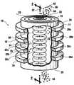
- FIG. 1is a perspective view of the centrifugal mass filter of the present invention with portions broken away for clarity;
- FIG. 2is a cross sectional view of a portion of the centrifugal mass filter as seen along the line 2 — 2 in FIG. 1 .
- the filter 10preferably includes a cylindrical shaped container 11 with a wall 12 having an inner surface 14 and an outer surface 16 .
- the container 11has a substantially open end 18 and a substantially open end 20 and is oriented on a central axis 22 .
- FIG. 1also shows that an outer conductor 24 comprising a plurality of annular coils 26 (of which the coils 26 a , 26 b , 26 c and 26 d are representative) is mounted on the outer surface 16 of the container wall 12 .
- an electrode 28which comprises a plurality of concentric rings that are positioned at the end 18 of container 11 around the central axis 22 .
- this electrode 28is used to establish a positive potential, V ctr , on the axis 22 .
- the electrode 28 or, alternatively, a spiral electrodecan be positioned at either end 18 or end 20 (or both) of container wall 12 for this purpose.
- the electrical potential at the container wall 12will be approximately zero so that a radially oriented electrical field, E r , is established between the central axis 22 and the container wall 12 substantially as shown in FIG. 2 .
- FIG. 1shows that the filter 10 of the present invention includes an inner conductor 30 which comprises a plurality of coils 32 (of which the coils 32 a , 32 b and 32 c are representative).
- the inner conductor 30surrounds a central passageway 33 inside the container 11 .
- the filter 10is configured to establish a plasma passageway 34 which extends from end 18 to end 20 between the inner surface 14 of the container wall 12 and the central axis 22 .
- the central passageway 33is a portion of the larger plasma passageway 34 .
- the radially oriented electric field E ris established in this passageway 34 and is oriented substantially perpendicular to the central axis 22 (see FIG. 2 ).
- a magnetic field B zis established in the passageway 34 by the concerted effects of both the outer conductor 24 and the inner conductor 30 which will be oriented substantially parallel to the central axis 22 .
- the magnetic field Bzwill, therefore, be crossed with the electric field E r in the passageway 34 .
- the particular configuration of the magnetic fieldcan, to some extent, be determined by the use of casings 35 (see coil 32 c ) which can be placed around each of the annular coils 32 . The result of all this for the magnetic field in the passageway 34 is best exemplified by the magnetic flux lines 36 shown in FIG. 2 (of which the flux lines 36 a , 36 b , 36 c and 36 d are representative).
- an electrical field, E ris established in the passageway 34 with positive potential, V ctr , on the central axis 22 , and a substantially zero potential at the container wall 12 .
- a magnetic field, B zis established in the passageway 34 .
- the magnetic field, B zthat is generated by the combined outputs of outer conductor 24 and inner conductor 30 , and is oriented in the passageway such that E r and B z are crossed with each other.
- a rotating multi-species plasma 38is then injected into the central passageway 33 through the end 18 .
- the multi-species plasma 38will include various types of specific elements which can be generally classified as either low-mass particles 40 , having a representative mass, M 1 , or high-mass particles 42 , having a representative mass, M 2 .
- M cis established so that M 1 ⁇ M c ⁇ M 2 .
- M cea 2 (B z ) 2 /8V ctr is that the low-mass particles 40 (M 1 ) will be confined within the passageway 34 during their transit through the filter 10 , while the high-mass particles 42 (M 2 ) will be ejected into the container wall 12 before they can completely transit the filter 10 .
- the configuration of the magnetic field that is created by the combined outputs of the outer conductor 24 (B z1 ) and inner conductor 30 (B z2 ), wherein the magnitude of the magnetic field varies from B z in the passageway 34 down to approximately zero on the central axis 22facilitates the separation of high-mass particles 42 from the low-mass particles 40 .
- M cea 2 (B z ) 2 /8V ctr
Landscapes
- Chemical & Material Sciences (AREA)
- Analytical Chemistry (AREA)
- Physical Or Chemical Processes And Apparatus (AREA)
- Manufacture Of Metal Powder And Suspensions Thereof (AREA)
Abstract
Description
Claims (14)
Priority Applications (1)
| Application Number | Priority Date | Filing Date | Title |
|---|---|---|---|
| US09/479,276US6217776B1 (en) | 1998-11-16 | 2000-01-05 | Centrifugal filter for multi-species plasma |
Applications Claiming Priority (2)
| Application Number | Priority Date | Filing Date | Title |
|---|---|---|---|
| US09/192,945US6096220A (en) | 1998-11-16 | 1998-11-16 | Plasma mass filter |
| US09/479,276US6217776B1 (en) | 1998-11-16 | 2000-01-05 | Centrifugal filter for multi-species plasma |
Related Parent Applications (1)
| Application Number | Title | Priority Date | Filing Date |
|---|---|---|---|
| US09/192,945Continuation-In-PartUS6096220A (en) | 1998-11-16 | 1998-11-16 | Plasma mass filter |
Publications (1)
| Publication Number | Publication Date |
|---|---|
| US6217776B1true US6217776B1 (en) | 2001-04-17 |
Family
ID=46203770
Family Applications (1)
| Application Number | Title | Priority Date | Filing Date |
|---|---|---|---|
| US09/479,276Expired - LifetimeUS6217776B1 (en) | 1998-11-16 | 2000-01-05 | Centrifugal filter for multi-species plasma |
Country Status (1)
| Country | Link |
|---|---|
| US (1) | US6217776B1 (en) |
Cited By (16)
| Publication number | Priority date | Publication date | Assignee | Title |
|---|---|---|---|---|
| US6304036B1 (en) | 2000-08-08 | 2001-10-16 | Archimedes Technology Group, Inc. | System and method for initiating plasma production |
| GB2369926A (en)* | 2000-10-12 | 2002-06-12 | Micromass Ltd | Mass spectrometer comprising vortex mass filter and analyser |
| US6521888B1 (en)* | 2000-01-20 | 2003-02-18 | Archimedes Technology Group, Inc. | Inverted orbit filter |
| US20030123992A1 (en)* | 2001-12-31 | 2003-07-03 | Mitrovic Andrej S. | Linear inductive plasma pump for process reactors |
| US20050133466A1 (en)* | 2003-12-19 | 2005-06-23 | Honeywell International Inc. | Multi-stage centrifugal debris trap |
| US20100294666A1 (en)* | 2009-05-19 | 2010-11-25 | Nonlinear Ion Dynamics, Llc | Integrated spin systems for the separation and recovery of isotopes |
| CN103413750A (en)* | 2012-12-12 | 2013-11-27 | 上海斯善质谱仪器有限公司 | Mass spectrum analyzer and analyzing method thereof |
| US8784666B2 (en) | 2009-05-19 | 2014-07-22 | Alfred Y. Wong | Integrated spin systems for the separation and recovery of gold, precious metals, rare earths and purification of water |
| CN104529047A (en)* | 2015-01-22 | 2015-04-22 | 深圳市爱玛特科技有限公司 | Front filter |
| US9121082B2 (en) | 2011-11-10 | 2015-09-01 | Advanced Magnetic Processes Inc. | Magneto-plasma separator and method for separation |
| US10269458B2 (en) | 2010-08-05 | 2019-04-23 | Alpha Ring International, Ltd. | Reactor using electrical and magnetic fields |
| US10274225B2 (en) | 2017-05-08 | 2019-04-30 | Alpha Ring International, Ltd. | Water heater |
| US10319480B2 (en) | 2010-08-05 | 2019-06-11 | Alpha Ring International, Ltd. | Fusion reactor using azimuthally accelerated plasma |
| US10515726B2 (en) | 2013-03-11 | 2019-12-24 | Alpha Ring International, Ltd. | Reducing the coulombic barrier to interacting reactants |
| US11495362B2 (en) | 2014-06-27 | 2022-11-08 | Alpha Ring International Limited | Methods, devices and systems for fusion reactions |
| US11642645B2 (en) | 2015-01-08 | 2023-05-09 | Alfred Y. Wong | Conversion of natural gas to liquid form using a rotation/separation system in a chemical reactor |
Citations (3)
| Publication number | Priority date | Publication date | Assignee | Title |
|---|---|---|---|---|
| US3722677A (en) | 1970-06-04 | 1973-03-27 | B Lehnert | Device for causing particles to move along curved paths |
| US4861477A (en) | 1988-02-04 | 1989-08-29 | Shiro Kimura | Tubular container for centrifugal separation |
| US5039312A (en) | 1990-02-09 | 1991-08-13 | The United States Of America As Represented By The Secretary Of The Interior | Gas separation with rotating plasma arc reactor |
- 2000
- 2000-01-05USUS09/479,276patent/US6217776B1/ennot_activeExpired - Lifetime
Patent Citations (3)
| Publication number | Priority date | Publication date | Assignee | Title |
|---|---|---|---|---|
| US3722677A (en) | 1970-06-04 | 1973-03-27 | B Lehnert | Device for causing particles to move along curved paths |
| US4861477A (en) | 1988-02-04 | 1989-08-29 | Shiro Kimura | Tubular container for centrifugal separation |
| US5039312A (en) | 1990-02-09 | 1991-08-13 | The United States Of America As Represented By The Secretary Of The Interior | Gas separation with rotating plasma arc reactor |
Non-Patent Citations (18)
| Title |
|---|
| Anders, Andre; Interaction of Vacuum-Arc-Generated Macroparticles with a Liquid Surface; American Institute of Physics; 1998. |
| Bittencourt, J.A., and Ludwig, G.O; Steady State Behavior of Rotating Plasmas in a Vacuum-Arc Centrifuge; Plasma Physics and Controlled Fusion, vol. 29, No. 5, pp. 601-620; Great Britain, 1987. |
| Bonnevier, Björn; Experimental Evidence of Element and Isotope Separation in a Rotating Plasma; Plasma Physics, vol. 13; pp. 763-744; Northern Ireland, 1971. |
| Dallaqua, R.S.; Del Bosco, E.; da Silva, R.P.; and Simpson, S.W.; Langmuir Probe Measurements in a Vacuum Arc Plasma Centrifuge; IEEE Transactions on Plasma Science, vol. 26, No. 3, pp. 1044-1051; Jun., 1998. |
| Dallaqua, R.S.; Simpson, S.W.; and Del Bosco, E; Radial Magnetic Field in Vacuum Arc Centrifuges; J. Phys. D.Apl.Phys., 30; pp. 2585-2590; UK, 1997. |
| Dallaqua, Renato Sérgio; Simpson, S.W. and Del Bosco, Edson; Experiments with Background Gas in a Vacuum Arc Centrifuge; IEEE Transactions on Plasma Science, vol. 24, No. 2; pp. 539-545; Apr., 1996. |
| Evans, P.J.; Paoloni, F. J.; Noorman, J. T. and Whichello, J. V.; Measurements of Mass Separation in a Vacuum-Arc Centrifuge; J. Appl phys, 6(1); pp. 115-118; Jul. 1, 1989. |
| Geva, M.; Krishnan, M; and Hirshfield, J. L.; Element and Isotope Separation in a Vacuum-Arc Centrifuge; J. Appl. Phys 56(5); pp. 1398-1413; Sep. 1, 1984. |
| Kim, C.; Jensen, R.V.; and Krishnan, M; Equilibria of a Rigidly Rotating Fully Ionized Plasma Column; J. Appl. Phys., vol. 61, No. 9; pp. 4689-4690; May, 1987. |
| Krishnan, M.; Centrifugal Isotope Separation in Zirconium Plasma; Phys. Fluids 26(9); pp. 2676-2682; Sep., 1983. |
| Krishnan, Mahadevan; and Prasad, Rahul R.; Parametric Analysis of Isotope Enrichment in a Vacuum-Arc Centrifuge; J. Appl. Phys. 57(11); pp. 4973-4980; Jun., 1, 1985. |
| Ohkawa, Tihiro et al.; Plasma Confinement in dc Octopole; Physical Review Letters; vol. 24, No. 3; Jan. 19, 1970. |
| Prasad, Rahul R. and Krishnan, Mahadevan; Theoretical and Experimental Study of Rotation in a Vacuum-Arc Centrifuge; J. Appl. Phys., vol. 61, No. 1; pp. 113-119; Jan. 1, 1987. |
| Prasad, Rahul R. and Mahadevan Krishnan; Article from J. Appl. Phys. 61(9); American Institute of Physics; pp. 4464-4470; May, 1987. |
| Qi, Niansheng and Krishnan, Mahadevan; Stable Isotope Production; p. 531. |
| Simpson, S.W.; Dallaqua, R.S.; and Del Bosco, E.; Acceleration Mechanism in Vacuum Arc Centrifuges; J. Phys. D: Appl. Phys. 29; pp. 1040-1046; UK, 1996. |
| Slepian, Joseph; Failure of the Ionic Centrifuge Prior to the Ionic Expander; p. 1283; Jun., 1955. |
| Yoshikawa, Masaji et al.; Plasma Confinement in a Toroidal Quadrupole; The Physics of Fluids; vol. 12, No. 9; Sep. 1969. |
Cited By (24)
| Publication number | Priority date | Publication date | Assignee | Title |
|---|---|---|---|---|
| US6521888B1 (en)* | 2000-01-20 | 2003-02-18 | Archimedes Technology Group, Inc. | Inverted orbit filter |
| US6304036B1 (en) | 2000-08-08 | 2001-10-16 | Archimedes Technology Group, Inc. | System and method for initiating plasma production |
| US6781116B2 (en) | 2000-10-12 | 2004-08-24 | Micromass Uk Limited | Mass spectrometer |
| GB2369926B (en)* | 2000-10-12 | 2003-02-12 | Micromass Ltd | Mass spectrometer |
| US20040016877A1 (en)* | 2000-10-12 | 2004-01-29 | Bateman Robert Harold | Mass spectrometer |
| GB2369926A (en)* | 2000-10-12 | 2002-06-12 | Micromass Ltd | Mass spectrometer comprising vortex mass filter and analyser |
| US20030123992A1 (en)* | 2001-12-31 | 2003-07-03 | Mitrovic Andrej S. | Linear inductive plasma pump for process reactors |
| US6824363B2 (en)* | 2001-12-31 | 2004-11-30 | Tokyo Electron Limited | Linear inductive plasma pump for process reactors |
| US20050133466A1 (en)* | 2003-12-19 | 2005-06-23 | Honeywell International Inc. | Multi-stage centrifugal debris trap |
| US7175771B2 (en) | 2003-12-19 | 2007-02-13 | Honeywell International, Inc. | Multi-stage centrifugal debris trap |
| US8784666B2 (en) | 2009-05-19 | 2014-07-22 | Alfred Y. Wong | Integrated spin systems for the separation and recovery of gold, precious metals, rare earths and purification of water |
| US20100294666A1 (en)* | 2009-05-19 | 2010-11-25 | Nonlinear Ion Dynamics, Llc | Integrated spin systems for the separation and recovery of isotopes |
| US8298318B2 (en)* | 2009-05-19 | 2012-10-30 | Wong Alfred Y | Integrated spin systems for the separation and recovery of isotopes |
| US10269458B2 (en) | 2010-08-05 | 2019-04-23 | Alpha Ring International, Ltd. | Reactor using electrical and magnetic fields |
| US10319480B2 (en) | 2010-08-05 | 2019-06-11 | Alpha Ring International, Ltd. | Fusion reactor using azimuthally accelerated plasma |
| US9121082B2 (en) | 2011-11-10 | 2015-09-01 | Advanced Magnetic Processes Inc. | Magneto-plasma separator and method for separation |
| CN103413750B (en)* | 2012-12-12 | 2016-02-17 | 上海斯善质谱仪器有限公司 | A kind of mass spectrometer and analytical method thereof |
| CN103413750A (en)* | 2012-12-12 | 2013-11-27 | 上海斯善质谱仪器有限公司 | Mass spectrum analyzer and analyzing method thereof |
| US10515726B2 (en) | 2013-03-11 | 2019-12-24 | Alpha Ring International, Ltd. | Reducing the coulombic barrier to interacting reactants |
| US11495362B2 (en) | 2014-06-27 | 2022-11-08 | Alpha Ring International Limited | Methods, devices and systems for fusion reactions |
| US11642645B2 (en) | 2015-01-08 | 2023-05-09 | Alfred Y. Wong | Conversion of natural gas to liquid form using a rotation/separation system in a chemical reactor |
| CN104529047A (en)* | 2015-01-22 | 2015-04-22 | 深圳市爱玛特科技有限公司 | Front filter |
| CN104529047B (en)* | 2015-01-22 | 2016-08-24 | 深圳市爱玛特科技有限公司 | A kind of fore filter |
| US10274225B2 (en) | 2017-05-08 | 2019-04-30 | Alpha Ring International, Ltd. | Water heater |
Similar Documents
| Publication | Publication Date | Title |
|---|---|---|
| US6217776B1 (en) | Centrifugal filter for multi-species plasma | |
| CA2288412C (en) | Plasma mass filter | |
| US6251282B1 (en) | Plasma filter with helical magnetic field | |
| US6322706B1 (en) | Radial plasma mass filter | |
| US6251281B1 (en) | Negative ion filter | |
| EP1220293B1 (en) | Tandem plasma mass filter | |
| US6214223B1 (en) | Toroidal plasma mass filter | |
| JP3721301B2 (en) | Plasma mass filter | |
| EP1458008A2 (en) | High frequency wave heated plasma mass filter | |
| US6956217B2 (en) | Mass separator with controlled input | |
| US6258216B1 (en) | Charged particle separator with drift compensation | |
| US4458148A (en) | Method and apparatus for separating substances of different atomic weights using a plasma centrifuge | |
| US6293406B1 (en) | Multi-mass filter | |
| US6521888B1 (en) | Inverted orbit filter | |
| US6723248B2 (en) | High throughput plasma mass filter | |
| US6541764B2 (en) | Helically symmetric plasma mass filter | |
| RU2142328C1 (en) | Apparatus for separating charged particles by mass | |
| US6294781B1 (en) | Electromagnetic mass distiller | |
| EP1220289A2 (en) | Plasma mass selector | |
| RU2171707C2 (en) | Device for charged particle mass separation |
Legal Events
| Date | Code | Title | Description |
|---|---|---|---|
| AS | Assignment | Owner name:ARCHIMEDES TECHNOLOGY GROUP, INC., CALIFORNIA Free format text:ASSIGNMENT OF ASSIGNORS INTEREST;ASSIGNOR:OHKAWA, TIHIRO;REEL/FRAME:010657/0909 Effective date:20000104 | |
| STCF | Information on status: patent grant | Free format text:PATENTED CASE | |
| CC | Certificate of correction | ||
| FPAY | Fee payment | Year of fee payment:4 | |
| AS | Assignment | Owner name:ARCHIMEDES OPERATING, LLC, CALIFORNIA Free format text:ASSIGNMENT OF ASSIGNORS INTEREST;ASSIGNOR:ARCHIMEDES TECHNOLOGY GROUP, INC.;REEL/FRAME:015661/0131 Effective date:20050203 | |
| REMI | Maintenance fee reminder mailed | ||
| FEPP | Fee payment procedure | Free format text:PAT HOLDER NO LONGER CLAIMS SMALL ENTITY STATUS, ENTITY STATUS SET TO UNDISCOUNTED (ORIGINAL EVENT CODE: STOL); ENTITY STATUS OF PATENT OWNER: LARGE ENTITY | |
| REFU | Refund | Free format text:REFUND - 7.5 YR SURCHARGE - LATE PMT W/IN 6 MO, SMALL ENTITY (ORIGINAL EVENT CODE: R2555); ENTITY STATUS OF PATENT OWNER: LARGE ENTITY Free format text:REFUND - PAYMENT OF MAINTENANCE FEE, 8TH YR, SMALL ENTITY (ORIGINAL EVENT CODE: R2552); ENTITY STATUS OF PATENT OWNER: LARGE ENTITY | |
| FPAY | Fee payment | Year of fee payment:8 | |
| SULP | Surcharge for late payment | Year of fee payment:7 | |
| FPAY | Fee payment | Year of fee payment:12 | |
| AS | Assignment | Owner name:GENERAL ATOMICS, CALIFORNIA Free format text:ASSIGNMENT OF ASSIGNORS INTEREST;ASSIGNORS:ARCHIMEDES TECHNOLOGY GROUP HOLDINGS LLC;ARCHIMEDES OPERATING LLC;ARCHIMEDES NUCLEAR WASTE LLC;REEL/FRAME:042581/0123 Effective date:20060802 | |
| AS | Assignment | Owner name:BANK OF THE WEST, CALIFORNIA Free format text:PATENT SECURITY AGREEMENT;ASSIGNOR:GENERAL ATOMICS;REEL/FRAME:042914/0365 Effective date:20170620 |