US6217758B1 - Oil sump arrangement with integral filter and heat exchanger - Google Patents
Oil sump arrangement with integral filter and heat exchangerDownload PDFInfo
- Publication number
- US6217758B1 US6217758B1US09/369,276US36927699AUS6217758B1US 6217758 B1US6217758 B1US 6217758B1US 36927699 AUS36927699 AUS 36927699AUS 6217758 B1US6217758 B1US 6217758B1
- Authority
- US
- United States
- Prior art keywords
- oil
- panel
- arrangement
- pan
- chamber
- Prior art date
- Legal status (The legal status is an assumption and is not a legal conclusion. Google has not performed a legal analysis and makes no representation as to the accuracy of the status listed.)
- Expired - Lifetime
Links
Images

Classifications
- F—MECHANICAL ENGINEERING; LIGHTING; HEATING; WEAPONS; BLASTING
- F01—MACHINES OR ENGINES IN GENERAL; ENGINE PLANTS IN GENERAL; STEAM ENGINES
- F01M—LUBRICATING OF MACHINES OR ENGINES IN GENERAL; LUBRICATING INTERNAL COMBUSTION ENGINES; CRANKCASE VENTILATING
- F01M11/00—Component parts, details or accessories, not provided for in, or of interest apart from, groups F01M1/00 - F01M9/00
- F01M11/0004—Oilsumps
- F01M2011/0058—Fastening to the transmission
- F—MECHANICAL ENGINEERING; LIGHTING; HEATING; WEAPONS; BLASTING
- F01—MACHINES OR ENGINES IN GENERAL; ENGINE PLANTS IN GENERAL; STEAM ENGINES
- F01M—LUBRICATING OF MACHINES OR ENGINES IN GENERAL; LUBRICATING INTERNAL COMBUSTION ENGINES; CRANKCASE VENTILATING
- F01M11/00—Component parts, details or accessories, not provided for in, or of interest apart from, groups F01M1/00 - F01M9/00
- F01M11/0004—Oilsumps
- F01M2011/0079—Oilsumps with the oil pump integrated or fixed to sump
- F—MECHANICAL ENGINEERING; LIGHTING; HEATING; WEAPONS; BLASTING
- F16—ENGINEERING ELEMENTS AND UNITS; GENERAL MEASURES FOR PRODUCING AND MAINTAINING EFFECTIVE FUNCTIONING OF MACHINES OR INSTALLATIONS; THERMAL INSULATION IN GENERAL
- F16H—GEARING
- F16H57/00—General details of gearing
- F16H57/04—Features relating to lubrication or cooling or heating
- F16H57/0402—Cleaning of lubricants, e.g. filters or magnets
- F16H57/0404—Lubricant filters
- F—MECHANICAL ENGINEERING; LIGHTING; HEATING; WEAPONS; BLASTING
- F16—ENGINEERING ELEMENTS AND UNITS; GENERAL MEASURES FOR PRODUCING AND MAINTAINING EFFECTIVE FUNCTIONING OF MACHINES OR INSTALLATIONS; THERMAL INSULATION IN GENERAL
- F16H—GEARING
- F16H57/00—General details of gearing
- F16H57/04—Features relating to lubrication or cooling or heating
- F16H57/0412—Cooling or heating; Control of temperature
- F16H57/0415—Air cooling or ventilation; Heat exchangers; Thermal insulations
- F16H57/0417—Heat exchangers adapted or integrated in the gearing
- F—MECHANICAL ENGINEERING; LIGHTING; HEATING; WEAPONS; BLASTING
- F16—ENGINEERING ELEMENTS AND UNITS; GENERAL MEASURES FOR PRODUCING AND MAINTAINING EFFECTIVE FUNCTIONING OF MACHINES OR INSTALLATIONS; THERMAL INSULATION IN GENERAL
- F16H—GEARING
- F16H57/00—General details of gearing
- F16H57/04—Features relating to lubrication or cooling or heating
- F16H57/045—Lubricant storage reservoirs, e.g. reservoirs in addition to a gear sump for collecting lubricant in the upper part of a gear case
- F16H57/0452—Oil pans
- F—MECHANICAL ENGINEERING; LIGHTING; HEATING; WEAPONS; BLASTING
- F16—ENGINEERING ELEMENTS AND UNITS; GENERAL MEASURES FOR PRODUCING AND MAINTAINING EFFECTIVE FUNCTIONING OF MACHINES OR INSTALLATIONS; THERMAL INSULATION IN GENERAL
- F16H—GEARING
- F16H57/00—General details of gearing
- F16H57/04—Features relating to lubrication or cooling or heating
- F16H57/0467—Elements of gearings to be lubricated, cooled or heated
- F16H57/0475—Engine and gearing, i.e. joint lubrication or cooling or heating thereof
Definitions
- the present inventionrelates to an oil sump arrangement with an integral filter and heat exchanger. More particularly, the present invention relates to an oil sump with an integral filter media and heat exchanger useful for treating transmission oil or lubricating oil used in a drive train, such as a drive train including an internal combustion engine having a radiator for circulating engine coolant.
- vehicleswhich are equipped with automatic, manual or semi-manual transmissions having recirculated transmission oil, cool the oil with a heat exchanger so that excessive heat build-up does not damage fragile engine parts.
- the usual location of the heat exchangeris near the radiator with hot transmission oil being pumped through small pipes to the heat exchanger. Coolant from the radiator is circulated through the heat exchanger to draw heat out of the oil and the cooled oil is then returned to the transmission.
- internal combustion enginesuse a spin-on oil filter, which of course projects out of an engine and consumes considerable space.
- an oil cooleris utilized in addition to the spin-on filter. Both the oil cooler and spin-on filter consume valuable space which can be used for other purposes as well as being used to provide additional space for engine access needed for service.
- an arrangement for treating oil circulated in a drive train including an engine, a transmission and a coolant sourcecomprises a sump pan having side walls and horizontally extending floor, wherein the sump pan includes an oil suction tube for returning oil pooled on the floor to the drive train.
- a panelis disposed in the sump pan in spaced relation to the floor thereof to divide the sump pan into a first chamber and a second chamber. The panel has an opening therethrough for connecting the two chambers in which a filter media is disposed. Oil collected in the first chamber passes through the filter media and pools in the second chamber, from which second chamber the oil is returned to the drive train by the suction tube.
- a heat exchangeris disposed in one of the chambers for cooling oil circulating through the sump pan, the heat exchanger being connected to the coolant source.
- the heat exchangeris integral with a panel, and in still a more specific aspect, the panel has an upstream surface facing into the first chamber and a downstream surface facing into the second chamber with the heat exchanger being on the upstream surface so as to cool the oil prior to the oil being filtered by the filter media.
- the panel, the filter media and the heat exchangerform an integral unit which is disposed within the sump pan and is separable therefrom.
- the arrangementis used to treat transmission oil or lubricating oil.
- FIG. 1is a side view of an internal combustion engine and transmission which comprise a drive train, the internal combustion including a radiator;
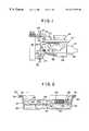
- FIG. 2is a side view of an oil sump used with the internal combustion engine of FIG. 1;
- FIG. 3is a perspective view of a panel insert used with the oil sump of FIG. 2 .
- an engine drive train 10which includes an internal combustion engine 12 and a transmission 14 , the transmission may be an automatic transmission, a manual transmission or a semi-manual transmission.
- the internal combustion engine 10is cooled by a radiator 16 which circulates coolant from the engine via a line 18 and returns the coolant to the engine via a line 20 by using a coolant pump 22 .
- the engine 12includes an oil sump pan 24 for pooling lubricating oil and the transmission includes an oil sump pan 26 for pooling transmission oil.
- the transmission oil pan 26provides an arrangement for treating oil circulated in the drive train 10 of FIG. 1 which includes an engine 12 , a transmission 14 and a coolant source in the form of the radiator 16 .
- the transmission oil pan 26is configured as a sump pan with a floor 30 and a side wall 32 .
- the transmission oil pan 26is connected to the bottom of the transmission 14 by a plurality of bolts 33 received through holes in a peripheral flange 34 . Oil enters the sump pan 26 through a drain 36 from the transmission 14 (FIG. 1) and is returned to the transmission by a suction tube 38 connected to a suction pump (not shown).
- a panel 40(see mainly FIG. 3) is disposed within the transmission oil pan 26 and divides the pan into a first chamber 42 and a second chamber 44 .
- the panel 42has at least one opening completely therethrough and as seen in FIG. 3, preferably has two openings 46 and 48 therethrough.
- Positioned within the openings 46 and 48are pleated filter media 50 and 52 , respectively. While pleated filter media 50 and 52 are illustrated, the filter media may also be of other configurations, but generally have the geometric form of panel-type filter media.
- the panel 42has an upstream surface 54 which faces into the first chamber 42 and a downstream surface 56 which faces into the second chamber 44 .
- a heat exchanger 60Disposed on the upstream surface 54 is a heat exchanger 60 which has a coolant inlet tube 62 and a coolant outlet tube 64 which are connected to the coolant pump 22 of FIG. 1 so that coolant which has been cooled by the radiator 16 is pumped through the heat exchanger 60 as the engine 12 runs.
- the heat exchanger 60is disposed on the upstream side of the filter media 50 and 52 so as to cool oil from the drain 36 before the oil is filtered. After the oil flows over the heat exchanger 60 , it passes through the filter media 50 and 52 into the second chamber 44 (FIG. 2 ), where it pools and is thereafter sucked from the second chamber by the suction tube 38 .
- the action of the suction tube 38creates a lower pressure on downstream surfaces 66 and 68 of filter media 50 and 52 which pulls oil accumulating in the first chamber 42 through the filter media.
- the panel 40is generally irregular in shape and has a peripheral sidewall 70 which encloses the first chamber 42 .
- the sidewall 70has a laterally projecting flange 72 which abuts the transmission housing and is sandwiched between the flange 34 on the sidewall 32 of the transmission oil pan 26 and the bottom surface of the transmission 14 .
- the panel 70is held in place by the bolts 32 (see FIG. 2 ).
- Molded into the flange 72is a groove 74 in which an integral gasket 76 is mounted.
- the pleated filter media 50 and 52are molded into the nylon panel 40 as is the heat exchange unit 60 .
- the coolant inlet tube 62 and coolant outlet tube 64are preferably molded into the sidewall 70 and the suction tube 38 which provides the fluid return is preferably molded into the panel 40 .
- the preferable material for the panel 40is NYLON® (polyamide).
- the lubricating oil pan 24can be similarly configured, i.e., to have at least one filter media, such as the filter media 50 and 52 molded therein and a heat exchanger, such as the heat exchanger 60 , molded therein. Consequently, lubricating oil can be treated by being first cooled by a heat exchanger 60 and thereafter filtered by filter media 50 and 52 before being returned to the engine 12 via a suction tube 38 .
Landscapes
- Engineering & Computer Science (AREA)
- Mechanical Engineering (AREA)
- General Engineering & Computer Science (AREA)
- Lubrication Of Internal Combustion Engines (AREA)
- Lubrication Details And Ventilation Of Internal Combustion Engines (AREA)
Abstract
Description
Claims (14)
Priority Applications (4)
| Application Number | Priority Date | Filing Date | Title |
|---|---|---|---|
| US09/369,276US6217758B1 (en) | 1999-08-06 | 1999-08-06 | Oil sump arrangement with integral filter and heat exchanger |
| CA002314764ACA2314764C (en) | 1999-08-06 | 2000-07-28 | Oil sump arrangement with integral filter and heat exchanger |
| GB0018942AGB2352806B (en) | 1999-08-06 | 2000-08-02 | A panel for removable disposition in an oil sump pan |
| DE10038081ADE10038081A1 (en) | 1999-08-06 | 2000-08-04 | An oil sump assembly |
Applications Claiming Priority (1)
| Application Number | Priority Date | Filing Date | Title |
|---|---|---|---|
| US09/369,276US6217758B1 (en) | 1999-08-06 | 1999-08-06 | Oil sump arrangement with integral filter and heat exchanger |
Publications (1)
| Publication Number | Publication Date |
|---|---|
| US6217758B1true US6217758B1 (en) | 2001-04-17 |
Family
ID=23454811
Family Applications (1)
| Application Number | Title | Priority Date | Filing Date |
|---|---|---|---|
| US09/369,276Expired - LifetimeUS6217758B1 (en) | 1999-08-06 | 1999-08-06 | Oil sump arrangement with integral filter and heat exchanger |
Country Status (4)
| Country | Link |
|---|---|
| US (1) | US6217758B1 (en) |
| CA (1) | CA2314764C (en) |
| DE (1) | DE10038081A1 (en) |
| GB (1) | GB2352806B (en) |
Cited By (48)
| Publication number | Priority date | Publication date | Assignee | Title |
|---|---|---|---|---|
| WO2002103170A1 (en)* | 2001-06-15 | 2002-12-27 | Sogefi Filtration Limited | Filter arrangement |
| US6705270B1 (en)* | 2000-04-26 | 2004-03-16 | Basf Corporation | Oil pan module for internal combustion engines |
| US20040173341A1 (en)* | 2002-04-25 | 2004-09-09 | George Moser | Oil cooler and production method |
| US20040177827A1 (en)* | 2003-03-13 | 2004-09-16 | Shore Line Industries, Inc. | Integral baffle and lubricant cooler |
| WO2004090386A1 (en)* | 2003-04-07 | 2004-10-21 | Zf Friedrichshafen Ag | Heat exchanger integrated in a transmission |
| EP1469170A3 (en)* | 2003-04-18 | 2005-08-31 | Isuzu Motors Limited | Oil pan structure |
| US20050202933A1 (en)* | 2004-03-15 | 2005-09-15 | Jagadish Sorab | Transmission fluid heating using engine exhaust |
| WO2007012312A1 (en)* | 2005-07-27 | 2007-02-01 | Luk Lamellen Und Kupplungsbau Beteiligungs Kg | Torque transmission device |
| US20080257625A1 (en)* | 2007-04-19 | 2008-10-23 | Antonio Stranges | Transmission oil pan |
| US20080290013A1 (en)* | 2007-05-22 | 2008-11-27 | Ibs Filtran Kunststoff-/Metallerzeugnisse Gmbh | Oil filter apparatus |
| US20090090494A1 (en)* | 2005-02-18 | 2009-04-09 | Ebm-Papst St. Georgen Gmbh & Co. Kg | Heat exchanger |
| US20090255369A1 (en)* | 2008-04-14 | 2009-10-15 | Solak Addison T | Fluid motion control device |
| US20100147105A1 (en)* | 2008-12-15 | 2010-06-17 | Zf Friedrichshafen Ag | Hybrid drive train of a motor vehicle |
| US20100212867A1 (en)* | 2009-02-25 | 2010-08-26 | Man Nutzfahrzeuge Ag | Cooling Device for Engine Oil and/or Transmission Oil, Particularly in an Internal Combustion Engine |
| US20110155489A1 (en)* | 2009-09-16 | 2011-06-30 | Swissauto Powersports Llc | Electric vehicle and on-board battery charging apparatus therefor |
| US20110226089A1 (en)* | 2010-03-22 | 2011-09-22 | Gm Global Technology Operations, Inc. | Transmission heating and storage device |
| US8372278B1 (en)* | 2012-03-21 | 2013-02-12 | GM Global Technology Operations LLC | Liquid fuel strainer assembly |
| US20130247864A1 (en)* | 2012-03-20 | 2013-09-26 | GM Global Technology Operations LLC | Compact transmission fluid heater |
| CN104728414A (en)* | 2015-03-24 | 2015-06-24 | 江苏泰隆减速机股份有限公司 | Reducer used for pulverizer of newly-increased auxiliary fuel tank |
| US9187083B2 (en) | 2009-09-16 | 2015-11-17 | Polaris Industries Inc. | System and method for charging an on-board battery of an electric vehicle |
| US20160010392A1 (en)* | 2013-03-05 | 2016-01-14 | Bentec Gmbh Drilling & Oilfield Systems | Driving device for driving drill pipes and method for operating such a driving device |
| US20160237867A1 (en)* | 2015-02-12 | 2016-08-18 | GM Global Technology Operations LLC | Oil pan and engine assembly including the oil pan |
| US20170051821A1 (en)* | 2015-08-17 | 2017-02-23 | GM Global Technology Operations LLC | Transmission pan with integrated heat exchanger |
| US20170328245A1 (en)* | 2016-05-13 | 2017-11-16 | Man Truck & Bus Ag | Apparatus for heating lubricating oil |
| US9976645B2 (en) | 2014-06-05 | 2018-05-22 | Ford Global Technologies, Llc | System and method of transferring heat between transmission fluid and coolant in oil pan |
| US10100736B2 (en) | 2015-10-30 | 2018-10-16 | General Electric Company | Gas turbine engine sump heat exchanger |
| US20180363762A1 (en)* | 2017-06-20 | 2018-12-20 | Toyota Jidosha Kabushiki Kaisha | Lubricating system of vehicle transmission device |
| US10300786B2 (en) | 2014-12-19 | 2019-05-28 | Polaris Industries Inc. | Utility vehicle |
| US10309524B2 (en)* | 2016-02-03 | 2019-06-04 | Toyota Jidosha Kabushiki Kaisha | Lubricating device of power transmission device for vehicle |
| US10344639B1 (en)* | 2017-03-31 | 2019-07-09 | Brunswick Corporation | Cooling apparatuses for cooling lubricant in a crankcase of a marine engine |
| US10408331B2 (en)* | 2015-07-21 | 2019-09-10 | Illinois Tool Works Inc. | Modular transmission side cover assembly |
| US10539076B2 (en) | 2015-11-10 | 2020-01-21 | General Electric Company | Self-contained lubrication cooling system with heat exchanger integrated with sump |
| US10634234B2 (en) | 2016-09-09 | 2020-04-28 | Zf Friedrichshafen Ag | Transmission |
| US10744868B2 (en) | 2016-06-14 | 2020-08-18 | Polaris Industries Inc. | Hybrid utility vehicle |
| US10780770B2 (en) | 2018-10-05 | 2020-09-22 | Polaris Industries Inc. | Hybrid utility vehicle |
| US11098621B2 (en)* | 2017-07-28 | 2021-08-24 | Ford Global Technologies, Llc | Oil sump assembly with an integrated oil filter |
| US11370266B2 (en) | 2019-05-16 | 2022-06-28 | Polaris Industries Inc. | Hybrid utility vehicle |
| US11702958B2 (en) | 2021-09-23 | 2023-07-18 | General Electric Company | System and method of regulating thermal transport bus pressure |
| US11788470B2 (en) | 2021-03-01 | 2023-10-17 | General Electric Company | Gas turbine engine thermal management |
| US12172518B2 (en) | 2019-04-30 | 2024-12-24 | Polaris Industries Inc. | Vehicle |
| US12188388B1 (en)* | 2021-11-21 | 2025-01-07 | Laverne Schumann | Oil heat exchanger |
| US12187127B2 (en) | 2020-05-15 | 2025-01-07 | Polaris Industries Inc. | Off-road vehicle |
| US12214654B2 (en) | 2021-05-05 | 2025-02-04 | Polaris Industries Inc. | Exhaust assembly for a utility vehicle |
| DE102006020801B4 (en)* | 2006-05-03 | 2025-05-08 | Sew-Eurodrive Gmbh & Co Kg | Cooling module for a gearbox, gearbox with cooling device and modular system for gearbox cooling devices |
| GB2636124A (en)* | 2023-11-29 | 2025-06-11 | Jaguar Land Rover Ltd | Housing for a drive unit |
| US12385429B2 (en) | 2022-06-13 | 2025-08-12 | Polaris Industries Inc. | Powertrain for a utility vehicle |
| US12384464B2 (en) | 2020-05-15 | 2025-08-12 | Polaris Industries Inc. | Off-road vehicle |
| US12410752B2 (en) | 2021-09-23 | 2025-09-09 | General Electric Company | System and method of detecting an airflow fault condition |
Families Citing this family (10)
| Publication number | Priority date | Publication date | Assignee | Title |
|---|---|---|---|---|
| DE20120862U1 (en) | 2001-12-22 | 2003-04-24 | Voss Automotive GmbH, 51688 Wipperfürth | Connecting device for an oil intake pipe of an internal combustion engine |
| DE102006024055A1 (en) | 2006-05-23 | 2007-11-29 | Volkswagen Ag | Module for pressure circulation lubrication of an internal combustion engine |
| US8042609B2 (en) | 2006-06-27 | 2011-10-25 | GM Global Technology Operations LLC | Method and apparatus for improving vehicle fuel economy |
| DE102007006896A1 (en)* | 2007-02-13 | 2008-01-24 | Audi Ag | Oil collection tank, especially sump, has heat exchanger in the form of one-piece cooling pipe whose ends are fed out of oil collection tank or sump |
| DE102008008585A1 (en)* | 2008-02-12 | 2009-08-13 | Bayerische Motoren Werke Aktiengesellschaft | Vehicle has gear, which is accommodated in gear housing and has gear oil circulation system, and gear oil circulation system is thermally coupled with coolant circuit over heat exchanger |
| CN102168629A (en)* | 2011-05-25 | 2011-08-31 | 中国兵器工业集团第七○研究所 | Integrated lower crankcase of engine |
| US20140260788A1 (en)* | 2011-10-05 | 2014-09-18 | Schaeffler Technologies Gmbh & Co. Kg | Gearbox device with cooled dry-sump area |
| DE102014016861B3 (en)* | 2014-11-14 | 2016-01-28 | Audi Ag | Internal combustion engine with an exhaust gas turbocharger |
| DE102017130019B4 (en) | 2017-12-14 | 2023-04-20 | Schaeffler Technologies AG & Co. KG | Oil pan with a filter device and motor vehicle |
| US20210207705A1 (en)* | 2020-01-06 | 2021-07-08 | GM Global Technology Operations LLC | Integrated oil capture and gasket system |
Citations (15)
| Publication number | Priority date | Publication date | Assignee | Title |
|---|---|---|---|---|
| US1305355A (en) | 1919-06-03 | Oiling mechanism fob | ||
| US1874585A (en) | 1927-08-18 | 1932-08-30 | Studebaker Corp | Internal combustion engine |
| US2063436A (en) | 1931-02-24 | 1936-12-08 | Frederic W Hild | Multiflow cooling for internal combustion engines |
| US2577188A (en) | 1948-04-01 | 1951-12-04 | Michael F Hall | Composite oil pan for engines |
| US2796239A (en)* | 1951-12-20 | 1957-06-18 | Gen Motors Corp | Heat exchanger |
| US3168468A (en) | 1961-05-12 | 1965-02-02 | Ford Motor Co | Filter assembly for transmissions |
| US3232283A (en) | 1964-05-15 | 1966-02-01 | Ed Taylor | Cooler for crankcase oil pan oil |
| US4352737A (en)* | 1979-09-19 | 1982-10-05 | Aisin Warner Kabushiki Kaisha | Strainer for automatic transmission control valve |
| JPS63225758A (en)* | 1987-03-16 | 1988-09-20 | Aisin Seiki Co Ltd | Oil cooler for automatic transmission |
| US4878536A (en) | 1987-02-16 | 1989-11-07 | Hypeco Ab | Combined filter and heat exchanger |
| JPH07103318A (en)* | 1993-09-30 | 1995-04-18 | Hino Motors Ltd | Lubricating device for transmission |
| US5408965A (en) | 1993-10-04 | 1995-04-25 | Ford Motor Company | Internal combustion engine oil pan with oil cooler |
| US5863424A (en)* | 1998-05-05 | 1999-01-26 | Dana Corporation | Filter element for oil pans and filter element/oil pan combination |
| US5937817A (en) | 1998-06-23 | 1999-08-17 | Harley-Davidson Motor Company | Dry sump oil cooling system |
| US6013179A (en)* | 1997-12-31 | 2000-01-11 | Dana Corporation | Filter having an integral gasket |
- 1999
- 1999-08-06USUS09/369,276patent/US6217758B1/ennot_activeExpired - Lifetime
- 2000
- 2000-07-28CACA002314764Apatent/CA2314764C/ennot_activeExpired - Lifetime
- 2000-08-02GBGB0018942Apatent/GB2352806B/ennot_activeExpired - Fee Related
- 2000-08-04DEDE10038081Apatent/DE10038081A1/ennot_activeWithdrawn
Patent Citations (15)
| Publication number | Priority date | Publication date | Assignee | Title |
|---|---|---|---|---|
| US1305355A (en) | 1919-06-03 | Oiling mechanism fob | ||
| US1874585A (en) | 1927-08-18 | 1932-08-30 | Studebaker Corp | Internal combustion engine |
| US2063436A (en) | 1931-02-24 | 1936-12-08 | Frederic W Hild | Multiflow cooling for internal combustion engines |
| US2577188A (en) | 1948-04-01 | 1951-12-04 | Michael F Hall | Composite oil pan for engines |
| US2796239A (en)* | 1951-12-20 | 1957-06-18 | Gen Motors Corp | Heat exchanger |
| US3168468A (en) | 1961-05-12 | 1965-02-02 | Ford Motor Co | Filter assembly for transmissions |
| US3232283A (en) | 1964-05-15 | 1966-02-01 | Ed Taylor | Cooler for crankcase oil pan oil |
| US4352737A (en)* | 1979-09-19 | 1982-10-05 | Aisin Warner Kabushiki Kaisha | Strainer for automatic transmission control valve |
| US4878536A (en) | 1987-02-16 | 1989-11-07 | Hypeco Ab | Combined filter and heat exchanger |
| JPS63225758A (en)* | 1987-03-16 | 1988-09-20 | Aisin Seiki Co Ltd | Oil cooler for automatic transmission |
| JPH07103318A (en)* | 1993-09-30 | 1995-04-18 | Hino Motors Ltd | Lubricating device for transmission |
| US5408965A (en) | 1993-10-04 | 1995-04-25 | Ford Motor Company | Internal combustion engine oil pan with oil cooler |
| US6013179A (en)* | 1997-12-31 | 2000-01-11 | Dana Corporation | Filter having an integral gasket |
| US5863424A (en)* | 1998-05-05 | 1999-01-26 | Dana Corporation | Filter element for oil pans and filter element/oil pan combination |
| US5937817A (en) | 1998-06-23 | 1999-08-17 | Harley-Davidson Motor Company | Dry sump oil cooling system |
Cited By (70)
| Publication number | Priority date | Publication date | Assignee | Title |
|---|---|---|---|---|
| US20050257766A1 (en)* | 2000-04-26 | 2005-11-24 | Walter Rau | Oil pan module for internal combustion engines |
| US6705270B1 (en)* | 2000-04-26 | 2004-03-16 | Basf Corporation | Oil pan module for internal combustion engines |
| WO2002103170A1 (en)* | 2001-06-15 | 2002-12-27 | Sogefi Filtration Limited | Filter arrangement |
| US20040173341A1 (en)* | 2002-04-25 | 2004-09-09 | George Moser | Oil cooler and production method |
| US20040177827A1 (en)* | 2003-03-13 | 2004-09-16 | Shore Line Industries, Inc. | Integral baffle and lubricant cooler |
| WO2004090386A1 (en)* | 2003-04-07 | 2004-10-21 | Zf Friedrichshafen Ag | Heat exchanger integrated in a transmission |
| US20060213462A1 (en)* | 2003-04-07 | 2006-09-28 | Gerhard Horing | Heat exchanger integrated in a transmission |
| EP1469170A3 (en)* | 2003-04-18 | 2005-08-31 | Isuzu Motors Limited | Oil pan structure |
| US20050202933A1 (en)* | 2004-03-15 | 2005-09-15 | Jagadish Sorab | Transmission fluid heating using engine exhaust |
| US7077776B2 (en)* | 2004-03-15 | 2006-07-18 | Ford Global Technologies, Llc | Transmission fluid heating using engine exhaust |
| US20090090494A1 (en)* | 2005-02-18 | 2009-04-09 | Ebm-Papst St. Georgen Gmbh & Co. Kg | Heat exchanger |
| US8459337B2 (en)* | 2005-02-18 | 2013-06-11 | Papst Licensing Gmbh & Co. Kg | Apparatus including a heat exchanger and equalizing vessel |
| WO2007012312A1 (en)* | 2005-07-27 | 2007-02-01 | Luk Lamellen Und Kupplungsbau Beteiligungs Kg | Torque transmission device |
| CN101233336B (en)* | 2005-07-27 | 2012-09-05 | 卢克摩擦片和离合器两合公司 | Torque transmission device |
| DE102006020801B4 (en)* | 2006-05-03 | 2025-05-08 | Sew-Eurodrive Gmbh & Co Kg | Cooling module for a gearbox, gearbox with cooling device and modular system for gearbox cooling devices |
| US20080257625A1 (en)* | 2007-04-19 | 2008-10-23 | Antonio Stranges | Transmission oil pan |
| US7637337B2 (en)* | 2007-04-19 | 2009-12-29 | Ford Global Technologies, Llc | Transmission oil pan |
| US8038877B2 (en)* | 2007-05-22 | 2011-10-18 | Ibs Filtran Kunststoff-/Metallerzeugnisse Gmbh | Oil filter apparatus |
| US20080290013A1 (en)* | 2007-05-22 | 2008-11-27 | Ibs Filtran Kunststoff-/Metallerzeugnisse Gmbh | Oil filter apparatus |
| US8607664B2 (en)* | 2008-04-14 | 2013-12-17 | GM Global Technology Operations LLC | Fluid motion control device |
| US20090255369A1 (en)* | 2008-04-14 | 2009-10-15 | Solak Addison T | Fluid motion control device |
| US20100147105A1 (en)* | 2008-12-15 | 2010-06-17 | Zf Friedrichshafen Ag | Hybrid drive train of a motor vehicle |
| US20100212867A1 (en)* | 2009-02-25 | 2010-08-26 | Man Nutzfahrzeuge Ag | Cooling Device for Engine Oil and/or Transmission Oil, Particularly in an Internal Combustion Engine |
| US9187083B2 (en) | 2009-09-16 | 2015-11-17 | Polaris Industries Inc. | System and method for charging an on-board battery of an electric vehicle |
| US20110155489A1 (en)* | 2009-09-16 | 2011-06-30 | Swissauto Powersports Llc | Electric vehicle and on-board battery charging apparatus therefor |
| US9802605B2 (en)* | 2009-09-16 | 2017-10-31 | Swissauto Powersport Llc | Electric vehicle and on-board battery charging apparatus therefor |
| US20110226089A1 (en)* | 2010-03-22 | 2011-09-22 | Gm Global Technology Operations, Inc. | Transmission heating and storage device |
| US8978515B2 (en)* | 2010-03-22 | 2015-03-17 | Gm Global Technology Operations, Llc | Transmission heating and storage device |
| US8622040B2 (en)* | 2012-03-20 | 2014-01-07 | GM Global Technology Operations LLC | Compact transmission fluid heater |
| US20130247864A1 (en)* | 2012-03-20 | 2013-09-26 | GM Global Technology Operations LLC | Compact transmission fluid heater |
| US8372278B1 (en)* | 2012-03-21 | 2013-02-12 | GM Global Technology Operations LLC | Liquid fuel strainer assembly |
| US20160010392A1 (en)* | 2013-03-05 | 2016-01-14 | Bentec Gmbh Drilling & Oilfield Systems | Driving device for driving drill pipes and method for operating such a driving device |
| US9976645B2 (en) | 2014-06-05 | 2018-05-22 | Ford Global Technologies, Llc | System and method of transferring heat between transmission fluid and coolant in oil pan |
| US12122228B2 (en) | 2014-12-19 | 2024-10-22 | Polaris Industries Inc. | Utility vehicle |
| US11884148B2 (en) | 2014-12-19 | 2024-01-30 | Polaris Industries Inc. | Utility vehicle |
| US10800250B2 (en) | 2014-12-19 | 2020-10-13 | Polaris Industries Inc. | Utility vehicle |
| US10300786B2 (en) | 2014-12-19 | 2019-05-28 | Polaris Industries Inc. | Utility vehicle |
| US20160237867A1 (en)* | 2015-02-12 | 2016-08-18 | GM Global Technology Operations LLC | Oil pan and engine assembly including the oil pan |
| CN104728414A (en)* | 2015-03-24 | 2015-06-24 | 江苏泰隆减速机股份有限公司 | Reducer used for pulverizer of newly-increased auxiliary fuel tank |
| US10408331B2 (en)* | 2015-07-21 | 2019-09-10 | Illinois Tool Works Inc. | Modular transmission side cover assembly |
| CN106468351A (en)* | 2015-08-17 | 2017-03-01 | 通用汽车环球科技运作有限责任公司 | There is the variator disc of integrated heat exchanger |
| DE102016114684B4 (en) | 2015-08-17 | 2022-12-22 | GM Global Technology Operations LLC | Transmission pan with integrated heat exchanger |
| US20170051821A1 (en)* | 2015-08-17 | 2017-02-23 | GM Global Technology Operations LLC | Transmission pan with integrated heat exchanger |
| US10100736B2 (en) | 2015-10-30 | 2018-10-16 | General Electric Company | Gas turbine engine sump heat exchanger |
| US10539076B2 (en) | 2015-11-10 | 2020-01-21 | General Electric Company | Self-contained lubrication cooling system with heat exchanger integrated with sump |
| US10309524B2 (en)* | 2016-02-03 | 2019-06-04 | Toyota Jidosha Kabushiki Kaisha | Lubricating device of power transmission device for vehicle |
| US20170328245A1 (en)* | 2016-05-13 | 2017-11-16 | Man Truck & Bus Ag | Apparatus for heating lubricating oil |
| US10744868B2 (en) | 2016-06-14 | 2020-08-18 | Polaris Industries Inc. | Hybrid utility vehicle |
| US10634234B2 (en) | 2016-09-09 | 2020-04-28 | Zf Friedrichshafen Ag | Transmission |
| US10344639B1 (en)* | 2017-03-31 | 2019-07-09 | Brunswick Corporation | Cooling apparatuses for cooling lubricant in a crankcase of a marine engine |
| US20180363762A1 (en)* | 2017-06-20 | 2018-12-20 | Toyota Jidosha Kabushiki Kaisha | Lubricating system of vehicle transmission device |
| US10738878B2 (en)* | 2017-06-20 | 2020-08-11 | Toyota Jidosha Kabushiki Kaisha | Lubricating system of vehicle transmission device |
| US11098621B2 (en)* | 2017-07-28 | 2021-08-24 | Ford Global Technologies, Llc | Oil sump assembly with an integrated oil filter |
| US12420624B2 (en) | 2018-10-05 | 2025-09-23 | Polaris Industries, Inc. | Hybrid utility vehicle |
| US10780770B2 (en) | 2018-10-05 | 2020-09-22 | Polaris Industries Inc. | Hybrid utility vehicle |
| US12172518B2 (en) | 2019-04-30 | 2024-12-24 | Polaris Industries Inc. | Vehicle |
| US11370266B2 (en) | 2019-05-16 | 2022-06-28 | Polaris Industries Inc. | Hybrid utility vehicle |
| US12311728B2 (en) | 2019-05-16 | 2025-05-27 | Polaris Industries Inc. | Hybrid utility vehicle |
| US12194808B2 (en) | 2019-05-16 | 2025-01-14 | Polaris Industries Inc. | Hybrid utility vehicle |
| US12187127B2 (en) | 2020-05-15 | 2025-01-07 | Polaris Industries Inc. | Off-road vehicle |
| US12337690B2 (en) | 2020-05-15 | 2025-06-24 | Polaris Industries Inc. | Off-road vehicle |
| US12384464B2 (en) | 2020-05-15 | 2025-08-12 | Polaris Industries Inc. | Off-road vehicle |
| US11788470B2 (en) | 2021-03-01 | 2023-10-17 | General Electric Company | Gas turbine engine thermal management |
| US12214654B2 (en) | 2021-05-05 | 2025-02-04 | Polaris Industries Inc. | Exhaust assembly for a utility vehicle |
| US12104499B2 (en) | 2021-09-23 | 2024-10-01 | General Electric Company | System and method of regulating thermal transport bus pressure |
| US12410752B2 (en) | 2021-09-23 | 2025-09-09 | General Electric Company | System and method of detecting an airflow fault condition |
| US11702958B2 (en) | 2021-09-23 | 2023-07-18 | General Electric Company | System and method of regulating thermal transport bus pressure |
| US12188388B1 (en)* | 2021-11-21 | 2025-01-07 | Laverne Schumann | Oil heat exchanger |
| US12385429B2 (en) | 2022-06-13 | 2025-08-12 | Polaris Industries Inc. | Powertrain for a utility vehicle |
| GB2636124A (en)* | 2023-11-29 | 2025-06-11 | Jaguar Land Rover Ltd | Housing for a drive unit |
Also Published As
| Publication number | Publication date |
|---|---|
| GB0018942D0 (en) | 2000-09-20 |
| CA2314764C (en) | 2007-11-20 |
| GB2352806A (en) | 2001-02-07 |
| CA2314764A1 (en) | 2001-02-06 |
| GB2352806B (en) | 2003-08-13 |
| DE10038081A1 (en) | 2001-03-29 |
Similar Documents
| Publication | Publication Date | Title |
|---|---|---|
| US6217758B1 (en) | Oil sump arrangement with integral filter and heat exchanger | |
| US7637337B2 (en) | Transmission oil pan | |
| US11365670B2 (en) | Method of modifying an engine oil cooling system | |
| US20040177827A1 (en) | Integral baffle and lubricant cooler | |
| US6058898A (en) | Structural oil pan with integrated oil filtration and cooling system | |
| US5678461A (en) | Transmission cooling system | |
| USRE45853E1 (en) | Oil filtering and cooling system for compression ignition engines | |
| US6021868A (en) | Mechanical transmission cooling and lubrication using associated engine systems | |
| US20130180496A1 (en) | Stepped oil-cooler | |
| US8720408B1 (en) | Oil filtering and cooling system for a vehicle compression ignition engine | |
| US5373892A (en) | Dry sump lubricated internal combustion engine with modular cooling system | |
| US20080023252A1 (en) | Power Steering Gear Cooling | |
| US7621251B1 (en) | Lubrication cooling system for a vehicle | |
| US6267881B1 (en) | Cooling system filter | |
| US7004232B1 (en) | Oil cooling oil tank | |
| CN1576526A (en) | Oil cooling equipment for engine | |
| JPH081129B2 (en) | Engine oil cooling system for water-cooled 4-cycle engine | |
| CN115342180B (en) | Single jackshaft AMT derailleur casing | |
| JP3872870B2 (en) | Oil cooler | |
| KR19980018838U (en) | Chiller of car engine oil filter | |
| MXPA99012010A (en) | Structural carter with cooling and filtration system of integr oil | |
| KR19980061452U (en) | Oil pan with pipe for oil cooling | |
| JPH07109913A (en) | Lubricator for engine with built-in oil pan |
Legal Events
| Date | Code | Title | Description |
|---|---|---|---|
| AS | Assignment | Owner name:DANA CORPORATION, OHIO Free format text:ASSIGNMENT OF ASSIGNORS INTEREST;ASSIGNOR:LEE, BRIAN THOMAS;REEL/FRAME:010496/0758 Effective date:19990722 | |
| STCF | Information on status: patent grant | Free format text:PATENTED CASE | |
| FPAY | Fee payment | Year of fee payment:4 | |
| AS | Assignment | Owner name:WIX FILTRATION CORP., NORTH CAROLINA Free format text:ASSIGNMENT OF ASSIGNORS INTEREST;ASSIGNOR:DANA CORPORATION;REEL/FRAME:015562/0231 Effective date:20041130 | |
| AS | Assignment | Owner name:JPMORGAN CHASE BANK, N.A., NEW YORK Free format text:SECURITY AGREEMENT;ASSIGNOR:WIX FILTRATION CORP.;REEL/FRAME:016153/0246 Effective date:20041130 | |
| AS | Assignment | Owner name:WIX FILTRATION CORP LLC, NORTH CAROLINA Free format text:CONVERSION FROM A CORPORATION TO A LIMITED LIABILITY COMPANY;ASSIGNOR:WIX FILTRATION CORP.;REEL/FRAME:019673/0582 Effective date:20070702 | |
| FPAY | Fee payment | Year of fee payment:8 | |
| AS | Assignment | Owner name:AFFINIA GROUP INC., MICHIGAN Free format text:PATENT RELEASE;ASSIGNOR:JPMORGAN CHASE BANK, N.A.;REEL/FRAME:023134/0704 Effective date:20090813 Owner name:BRAKE PARTS INC., MICHIGAN Free format text:PATENT RELEASE;ASSIGNOR:JPMORGAN CHASE BANK, N.A.;REEL/FRAME:023134/0704 Effective date:20090813 Owner name:WIX FILTRATION CORP. LLC, MICHIGAN Free format text:PATENT RELEASE;ASSIGNOR:JPMORGAN CHASE BANK, N.A.;REEL/FRAME:023134/0704 Effective date:20090813 Owner name:WILMINGTON TRUST FSB, AS NOTEHOLDER COLLATERAL AGE Free format text:SECURITY AGREEMENT;ASSIGNOR:WIX FILTRATION CORP. LLC;REEL/FRAME:023134/0898 Effective date:20090813 Owner name:BANK OF AMERICA, N.A., AS ABL COLLATERAL AGENT, MI Free format text:SECURITY AGREEMENT;ASSIGNOR:WIX FILTRATION CORP. LLC;REEL/FRAME:023134/0898 Effective date:20090813 Owner name:AFFINIA GROUP INC.,MICHIGAN Free format text:PATENT RELEASE;ASSIGNOR:JPMORGAN CHASE BANK, N.A.;REEL/FRAME:023134/0704 Effective date:20090813 Owner name:BRAKE PARTS INC.,MICHIGAN Free format text:PATENT RELEASE;ASSIGNOR:JPMORGAN CHASE BANK, N.A.;REEL/FRAME:023134/0704 Effective date:20090813 Owner name:WIX FILTRATION CORP. LLC,MICHIGAN Free format text:PATENT RELEASE;ASSIGNOR:JPMORGAN CHASE BANK, N.A.;REEL/FRAME:023134/0704 Effective date:20090813 Owner name:BANK OF AMERICA, N.A., AS ABL COLLATERAL AGENT,MIC Free format text:SECURITY AGREEMENT;ASSIGNOR:WIX FILTRATION CORP. LLC;REEL/FRAME:023134/0898 Effective date:20090813 Owner name:WILMINGTON TRUST FSB, AS NOTEHOLDER COLLATERAL AGENT, MINNESOTA Free format text:SECURITY AGREEMENT;ASSIGNOR:WIX FILTRATION CORP. LLC;REEL/FRAME:023134/0898 Effective date:20090813 Owner name:BANK OF AMERICA, N.A., AS ABL COLLATERAL AGENT, MICHIGAN Free format text:SECURITY AGREEMENT;ASSIGNOR:WIX FILTRATION CORP. LLC;REEL/FRAME:023134/0898 Effective date:20090813 | |
| FPAY | Fee payment | Year of fee payment:12 | |
| AS | Assignment | Owner name:BANK OF AMERICA, N.A., AS ADMINISTRATIVE AGENT, MI Free format text:SECURITY AGREEMENT;ASSIGNOR:WIX FILTRATION CORP LLC;REEL/FRAME:030291/0354 Effective date:20130425 Owner name:BANK OF AMERICA, N.A., AS ADMINISTRATIVE AGENT, MICHIGAN Free format text:SECURITY AGREEMENT;ASSIGNOR:WIX FILTRATION CORP LLC;REEL/FRAME:030291/0354 Effective date:20130425 | |
| AS | Assignment | Owner name:WIX FILTRATION CORP LLC, NORTH CAROLINA Free format text:TERMINATION AND RELEASE OF SECURITY INTEREST IN PATENT RIGHTS;ASSIGNORS:WILMINGTON TRUST, NATIONAL ASSOCIATION (AS SUCCESSOR BY MERGER TO WILMINGTON TRUST FSB);BANK OF AMERICA, N.A.;REEL/FRAME:030416/0052 Effective date:20130425 | |
| AS | Assignment | Owner name:JPMORGAN CHASE BANK, N.A., AS ADMINISTRATIVE AGENT, ILLINOIS Free format text:SECURITY AGREEMENT;ASSIGNOR:WIX FILTRATION CORP LLC;REEL/FRAME:030466/0180 Effective date:20130425 Owner name:JPMORGAN CHASE BANK, N.A., AS ADMINISTRATIVE AGENT Free format text:SECURITY AGREEMENT;ASSIGNOR:WIX FILTRATION CORP LLC;REEL/FRAME:030466/0180 Effective date:20130425 | |
| AS | Assignment | Owner name:WIX FILTRATION CORP LLC, NORTH CAROLINA Free format text:RELEASE BY SECURED PARTY;ASSIGNOR:BANK OF AMERICA, N.A.;REEL/FRAME:038663/0231 Effective date:20160504 | |
| AS | Assignment | Owner name:WIX FILTRATION CORP LLC, NORTH CAROLINA Free format text:RELEASE BY SECURED PARTY;ASSIGNOR:JPMORGAN CHASE BANK N.A.;REEL/FRAME:038665/0551 Effective date:20160504 |