US6217595B1 - Rotational atherectomy device - Google Patents
Rotational atherectomy deviceDownload PDFInfo
- Publication number
- US6217595B1 US6217595B1US09/225,370US22537099AUS6217595B1US 6217595 B1US6217595 B1US 6217595B1US 22537099 AUS22537099 AUS 22537099AUS 6217595 B1US6217595 B1US 6217595B1
- Authority
- US
- United States
- Prior art keywords
- helical coil
- drive shaft
- segment
- outer helical
- coil
- Prior art date
- Legal status (The legal status is an assumption and is not a legal conclusion. Google has not performed a legal analysis and makes no representation as to the accuracy of the status listed.)
- Expired - Lifetime
Links
Images


Classifications
- A—HUMAN NECESSITIES
- A61—MEDICAL OR VETERINARY SCIENCE; HYGIENE
- A61B—DIAGNOSIS; SURGERY; IDENTIFICATION
- A61B17/00—Surgical instruments, devices or methods
- A61B17/32—Surgical cutting instruments
- A61B17/3205—Excision instruments
- A61B17/3207—Atherectomy devices working by cutting or abrading; Similar devices specially adapted for non-vascular obstructions
- A61B17/320758—Atherectomy devices working by cutting or abrading; Similar devices specially adapted for non-vascular obstructions with a rotating cutting instrument, e.g. motor driven
- A—HUMAN NECESSITIES
- A61—MEDICAL OR VETERINARY SCIENCE; HYGIENE
- A61B—DIAGNOSIS; SURGERY; IDENTIFICATION
- A61B17/00—Surgical instruments, devices or methods
- A61B2017/00681—Aspects not otherwise provided for
- A61B2017/00685—Archimedes screw
- A—HUMAN NECESSITIES
- A61—MEDICAL OR VETERINARY SCIENCE; HYGIENE
- A61B—DIAGNOSIS; SURGERY; IDENTIFICATION
- A61B17/00—Surgical instruments, devices or methods
- A61B17/32—Surgical cutting instruments
- A61B2017/320004—Surgical cutting instruments abrasive
- A—HUMAN NECESSITIES
- A61—MEDICAL OR VETERINARY SCIENCE; HYGIENE
- A61B—DIAGNOSIS; SURGERY; IDENTIFICATION
- A61B90/00—Instruments, implements or accessories specially adapted for surgery or diagnosis and not covered by any of the groups A61B1/00 - A61B50/00, e.g. for luxation treatment or for protecting wound edges
- A61B90/36—Image-producing devices or illumination devices not otherwise provided for
- A61B90/37—Surgical systems with images on a monitor during operation
- A61B2090/378—Surgical systems with images on a monitor during operation using ultrasound
- A61B2090/3782—Surgical systems with images on a monitor during operation using ultrasound transmitter or receiver in catheter or minimal invasive instrument
Definitions
- the present inventionprovides an improved drive shaft for use with rotational atherectomy devices.
- a variety of techniques and instrumentshave been developed for use in the removal or repair of tissue in arteries and similar body passageways.
- a frequent objective of such techniques and instrumentsis the removal of atherosclerotic plaques in a patient's arteries.
- Atherosclerosisis characterized by a build-up of fatty deposits (atheromas) in the intimal layer (under the endothelium) of a patient's blood vessels.
- Is initially deposited as relatively soft cholesterol-rich atheromatous materialhardens into a calcified atherosclerotic plaque.
- Such atheromasrestrict the flow of blood, and therefore often are referred to as stenotic lesions or stenoses, the blocking material being referred to as stenotic material. If left untreated, such stenoses can cause angina, hypertension, myocardial infarction, strokes and the like.
- Atherectomy deviceshave been developed for attempting to remove some or all of such stenotic material.
- a rotating burr covered with an abrasive cutting materialsuch as diamond grit (diamond particles or dust) is carried at the distal end of a flexible drive shaft.
- an abrasive cutting materialsuch as diamond grit (diamond particles or dust)
- RotablatorOne atherectomy device commercially available from Heart Technologies, Inc. of Bellevue, Washington, U.S.A. is sold under the trade name Rotablator.
- the design of the Rotablator deviceis, to a significant extent, based on the design described in the Auth patent and the Rotablator device is typically rotated at speeds in the range of about 150,000-190,000 rpm.
- Auth's burris made from a solid, inflexible metal which is physically attached to a flexible, trifilar, helically wound drive shaft. This solid burr must be kept relatively short in order to allow the burr to navigate the bends and curves in tortuous arteries. At the same time, it must be sufficiently long to ensure reliable fixation of the burr to the drive shaft.
- the abrasive drive shaft atherectomy device disclosed in the above-mentioned Shturman patenttypically is used over a guide wire and includes a flexible, elongated drive shaft made from one or more helically wound wires. Wire turns of the proximal segment of the drive shaft have a generally constant diameter, while wire turns of a segment of the drive shaft near its distal end have an enlarged diameter. At least part of the enlarged diameter segment includes an external coating of an abrasive material to define an abrasive segment of the drive shaft which, when rotated at high speeds, is usable to remove stenotic tissue from an artery.
- the present inventionprovides a novel rotational atherectomy device which includes an improved drive shaft and a method of making the same. Certain embodiments of the invention provide improvements over the atherectomy device taught in the Shturman patent mentioned above.
- a rotational atherectomy device of the inventionincludes a flexible, elongated drive shaft having a central lumen for receipt of a guide wire therein around which the drive shaft may be rotated.
- the drive shafthas inner and outer co-axial wire layers helically wound in opposite directions so that the outer layer tends to radially contract and the inner layer tends to radially expand when the drive shaft is rotated in a predetermined direction.
- the outer layer of this embodimentcomprises a mono-filar helically wound coil and the inner layer comprises a multi-filar helically wound coil received in the lumen of the outer layer.
- this constructionmakes it easier to cost-effectively manufacture an appropriately shaped device with suitable mechanical properties.
- This drive shafthas proximal, intermediate and distal segments, with the outer layer of the intermediate segment of the drive shaft having a diameter which gradually increases distally through its proximal portion and gradually decreases distally through its distal portion, thereby defining an enlarged diameter segment of the drive shaft.
- At least part of this enlarged diameter segmentdesirably includes an external coating of an abrasive material to define an abrasive segment of the drive shaft which functions as an enlarged diameter tissue removal segment of the device. If wire turns along the distal portion of the intermediate segment are spaced from one another, then the abrasive material is optimally bonded to individual wire turns along at least part of the distal portion of the intermediate segment.
- wire turns of the outer layer along the abrasive segmentare not spaced from one another, one can apply abrasive material using a binder which not only bonds abrasive material to the wire turns, but also bonds at least some of the wire turns to one another along at least part of the abrasive segment.
- a rotational atherectomy deviceincludes at least two helically wound wires forming inner and outer co-axial wire layers which preferably are helically wound in opposite directions, as mentioned above.
- the outer layerhas an increased diameter along at least part of its length to define an enlarged diameter segment of the drive shaft.
- the precise shape of this enlarged diameter segment of the drive shaftcan be varied.
- wire turns of the inner layer of the drive shaftare spaced from one another along the enlarged diameter segment of the drive shaft. This has been found to further improve flexibility of the device while maintaining an appropriate shape in the enlarged diameter segment when the drive shaft is bent in operation, e.g. to keep wire turns of the enlarged diameter segment from falling out of alignment with one another when the drive shaft is bent or flexed to track curvatures of an artery or other vascular structure.
- One preferred rotational atherectomy device of the inventionincludes a flexible, elongated drive shaft having at least two helically wound wires forming inner and outer co-axial wire layers helically wound in opposite directions so that the outer layer tends to radially contract and the inner layer tends to radially expand when the drive shaft is rotated in a predetermined direction.
- the drive shafthas proximal, intermediate and distal segments, with wire turns of the outer layer of the intermediate segment of the drive shaft having diameters that increase distally at a generally constant rate through a proximal portion of such intermediate segment thereby forming generally the shape of a cone. At least some adjacent wire turns of the inner layer of the intermediate segment of the drive shaft are spaced from one another, improving flexibility of the intermediate segment of the drive shaft.
- At least part of a distal portion of the intermediate segment of the outer layerincludes an external coating of an abrasive material to define an abrasive segment of the drive shaft.
- an abrasive drive shaft atherectomy devicein another embodiment, includes a flexible, elongated drive shaft comprising at least one helically wound wire and having a central lumen for receipt of a guide wire therein around which the drive shaft may be rotated.
- this atherectomy devicehas proximal, intermediate and distal segments.
- the intermediate segment of the drive shafthas a diameter which gradually increases distally through its proximal portion and gradually decreases distally through its distal portion, thereby defining an enlarged diameter segment of the drive shaft.
- adjacent turns of the helically wound wireare spaced from one another along at least a portion of the enlarged diameter Intermediate segment, the spacing between adjacent wire turns along the intermediate segment gradually increasing distally through its proximal portion. In a preferred construction of this embodiment, the spacing between adjacent wire turns gradually decreases distally through the distal portion of the intermediate segment.
- At least part of the enlarged diameter intermediate segmentincludes an external coating of an abrasive material to define an abrasive segment of the drive shaft. If wire turns along the distal portion of the intermediate segment are spaced from one another, then the abrasive material is optimally bonded to individual wire turns along at least part of the distal portion of the intermediate segment.
- wire turns along the distal portion of the intermediate segmentare not spaced from one another, one can apply abrasive material using a binder which not only bonds abrasive material to the wire turns, but also bonds at least some of the wire turns to one another along at least part of the distal portion of the intermediate segment.
- Another aspect of the inventionprovides a method of manufacturing a flexible drive shaft for driving an operational element of a medical device.
- oneforms an inner helical coil by winding a plurality of wires about a forming mandrel, yielding a coil having a lumen and a proximal end.
- An outer helical coilis formed by winding a single wire with a mandrel-less coil forming machine, also yielding a coil having a lumen and a proximal end.
- the inner helical coilis then positioned within the lumen of the outer helical coil, orienting the coils such that the inner helical coil is wound in a clockwise direction and the outer helical coil is wound in a counter-clockwise direction.
- these relative orientationscan be switched when viewed from the proximal end of the device, but they will, of course, have the opposite relative orientations when viewed from the distal end.
- the proximal ends of the inner and outer helical coilsmay then be attached to a common driver and rotated.
- An inner helical coilis formed by winding a plurality of wires about a forming mandrel to yield a coil having a lumen, an intermediate segment and a proximal end, at least some adjacent wire turns being spaced from one another along at least part of the intermediate segment.
- An outer helical coilis formed by winding a single wire with a mandrel-less coil forming machine to produce a coil having a lumen, an intermediate segment and a proximal end, the diameters of the wire turns being gradually increased distally through a proximal portion of the intermediate segment and gradually decreased distally through a distal portion of the intermediate segment, thereby defining an enlarged diameter segment of the outer layer.
- the inner helical coilis positioned within the lumen of the outer helical coil, with the intermediate segment of the inner helical coil being positioned generally within the intermediate segment of the outer helical coil.
- the inner and outer helical coilsare optimally oriented such that the inner helical coil is wound in a clockwise direction and the outer helical coil is wound in a counterclockwise direction.
- a length of the enlarged diameter segment of the outer helical coilis coated with an abrasive material to define an abrasive segment of the drive shaft.
- the abrasive materialcan be applied either before or after the inner layer is positioned within the outer layer.
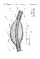
- FIG. 1is a perspective view of an atherectomy device of an embodiment of the invention
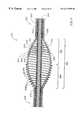
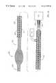
- FIG. 2is a broken-away, longitudinal cross-sectional view of the enlarged diameter segment of the drive shaft of the atherectomy device shown in FIG. 1;
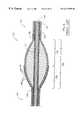
- FIG. 3is a broken-away, longitudinal cross-sectional view of the drive shaft of the atherectomy device of FIG. 2 depicted in a curved configuration;
- FIG. 4is a broken-away, longitudinal cross-sectional view of the enlarged diameter segment of the drive shaft of an alternative embodiment of an atherectomy device of the invention
- FIG. 5is a broken-away, longitudinal cross-sectional view of the drive shaft of the atherectomy device of FIG. 4 depicted In a curved configuration;
- FIG. 6is a broken-away, longitudinal cross-sectional view of the enlarged diameter segment of the drive shaft of another embodiment of the invention.
- FIG. 7is a broken-away, longitudinal cross-sectional view of the drive shaft of the atherectomy device of FIG. 6 in a curved configuration
- FIG. 8is a broken-away, longitudinal cross-sectional view of the enlarged diameter segment of the drive shaft of a prior art atherectomy device
- FIG. 9is a broken-away, longitudinal cross-sectional view of the drive shaft of the prior art atherectomy device of FIG. 8 depicted in a curved configuration;
- FIG. 10is a schematic cross-sectional view of the drive shaft of the atherectomy device of FIG. 2 taken along lines 10 — 10 thereof;
- FIG. 11is a schematic broken-away, longitudinal cross-sectional view of the drive shaft of the atherectomy device of FIG. 6 placed within a patient's vessel;
- FIG. 12is a broken-away, longitudinal cross-sectional view of the enlarged diameter segment of the drive shaft of a modified embodiment of the invention utilizing a mono-filar drive shaft;
- FIG. 13is a broken-away, longitudinal cross-sectional view of the drive shaft of the atherectomy device of FIG. 12 depicted In a curved configuration;
- FIG. 14is a broken-away, longitudinal cross-sectional view of the enlarged diameter segment of a modified embodiment of the invention, similar to FIG. 6, with the addition of ultrasound imaging transducers carried within a flexible bushing;
- FIG. 15is a broken-away, longitudinal cross-sectional view of the enlarged diameter segment of another modified embodiment of the invention wherein ultrasound imaging transducers and processors are retained within a larger diameter bushing;
- FIG. 16is a schematic view of a modified embodiment of the invention having spaces between adjacent wire turns along most of the length of the outer layer of the proximal segment of the drive shaft.
- FIG. 1illustrates a typical rotational atherectomy device in accordance with at least some of the embodiments of the present invention.
- the deviceincludes a handle portion 10 , with an elongated, flexible drive shaft 20 and an elongated catheter 13 extending distally from the handle portion 10 .
- the drive shaft 20includes a proximal segment 22 , an enlarged diameter intermediate segment 30 and a distal segment 24 . At least part of the distal portion 34 of the enlarged diameter intermediate segment 30 is coated with an abrasive material and defines an enlarged diameter tissue removal segment of the drive shaft.
- the catheter 13has a lumen in which most of the proximal segment of the drive shaft 20 is disposed.
- the drive shaft 20also includes an inner lumen, permitting the drive shaft 20 to be advanced and rotated over a guide wire 14 .
- the handle 10desirably contains a driver, such as a turbine or similar rotational drive mechanism, for rotating the drive shaft 20 .
- the handle 10typically may be connected to a power source (such as compressed gas) and a source of physiological solution (used for cooling and lubrication) delivered through suitable tubing, neither of which are illustrated for the sake of clarity.
- the handle 10also desirably includes a control knob 11 for advancing and retracting the driver and drive shaft 20 with respect to the catheter 13 and the body of the handle. Details regarding such handles and associated instrumentation are well known in the industry, and are described, e.g., in U.S. Pat. No. 5,314,407 (issued to Auth) and U.S. Pat. No. 5,314,438 (issued to Shturman), the teachings of which are incorporated herein by reference. The details of the handle form no part of this invention and need not be described in any great detail here.
- FIGS. 2-7 and 10 - 16all illustrate different embodiments of medical devices incorporating a flexible, elongated drive shaft in accordance with the present invention.
- this drive shaftgenerally includes an inner helical layer 40 and an outer helical layer 50 .
- Each of these layerscomprises a wire or wires helically wound to define a helical coil.
- These two helical layers of the drive shaftare desirably arranged such that the inner helical layer 40 is received within the lumen of the outer helical layer 50 in a generally co-axial fashion.
- the inner and outer helical layersoptimally are helically wound in opposite directions and have their proximal ends attached to a common driver, such as the turbine noted above.
- a common driversuch as the turbine noted above.
- thiswill apply torque to the proximal end of the drive shaft 20 and the outer helical layer 50 will tend to radially contract while the inner helical layer 40 will tend to radially expand, urging the two wire layers into radially compressive engagement.
- These two wire layersthus support one another and prevent the outer diameter of the drive shaft from significantly increasing or the diameter of the lumen 48 of the inner layer from appreciably decreasing. This permits the drive shaft to be used within a catheter of a fixed size and rotated about a guide wire without having to worry about the drive shaft locking up against the lumen of the catheter or locking down on the guide wire.
- FIGS. 7, 8 and 22 of that Shturman patentshow an atherectomy device using a drive shaft with a two-layer construction. It has been found, though, that such a construction can be relatively difficult and time-consuming to manufacture, particularly where the two-layer construction is used along the entire length of the drive shaft of the type shown in FIG. 8 of the Shturman patent.
- the inner helical layer 40comprises a plurality of wires (i.e., is multi-filar) while the outer helical layer Is formed of a single wire (i.e., is mono-filar).
- a drive shaft 20 in accordance with the present inventionis believed to yield superior torque-delivering capabilities over a device which uses mono-filar inner and outer layers (provided that all of the wires employed in the inner helical layer 40 each have the same diameter as the single wire in a mono-filar inner layer).
- the drive shaft of the present inventioncan be manufactured fairly cost effectively without compromising tolerance requirements of the lumen 48 of the drive shaft or unduly limiting the ability to modify the exterior shape of the enlarged diameter segment of the outer layer 50 to meet varied design objectives.
- the inner helical layer 40is comprised of at least three wires, illustrated in FIG. 2 as first, second and third wires 41 , 42 and 43 , respectively.
- This plurality of wirescan be wound about a forming mandrel using techniques well known in the medical device industry.
- Each of the wires 41 , 42 and 43can be arranged immediately adjacent one another to yield a coil wherein adjacent turns are formed from different wires.
- Groups 44 of these three wirescan be positioned essentially without gaps (as shown in the proximal segment 22 ) or with gaps 46 between adjacent turns of groups of wires to enhance flexibility.
- FIG. 10is a schematic cross-sectional view of the drive shaft of FIG. 2 taken along lines 10 — 10 .
- This viewwould obviously be much more complicated if the spiral pattern formed by the distally increasing diameters of the wire turns of the outer layer 50 would be shown.
- FIG. 10, though,essentially represents the shape of the face of such a cross section, simplifying the drawing for purposes of discussion.
- the entire cross-sectional area of the outer layer 50is made up from the thickness of a single wire strand. This requires that all of the torsional force delivered by the outer layer 50 be delivered through that single strand.
- the cross-sectional area of the inner layer 40is fairly evenly divided between the three wire strands 41 , 42 and 43 . This means that the torsional force being delivered through the inner layer at any given point along its length is being divided substantially equally between the three wires, reducing the load on each individual wire. A majority of the torque can be delivered through the inner layer without unduly sacrificing flexibility of the drive shaft, thereby permitting the shape of the enlarged diameter segment of the outer layer to be optimized for tissue removal without needing to focus on the ability of the outer layer to deliver torque.
- an inner helical coil 40is formed by winding a plurality of wires 41 , 42 and 43 about a forming mandrel.
- the wiresmay be of any suitable size or material.
- all of the wires of the Inner layerwill be formed of substantially the same material and have substantially the same diameter and cross-sectional shape.
- the diameter and material of the wires used in forming the inner helical coilwill obviously depend to a large extent on the diameter of the vessels in which the drive shaft is to be used and the amount of torque which needs to be delivered.
- a drive shaft 20 used in connection with a rotational atherectomy devicesuch as that illustrated in FIG. 2 (discussed in greater detail below) and has a maximum diameter of its enlarged diameter intermediate segment of about 2 mm
- three round stainless steel wires, each having a diameter of between about 0.002 inches and about 0.008 incheswill typically be used, with diameters in the range of about 0.003-0.006 inches being believed to be most preferable.
- Each of the wires 41 - 43 of the inner layer 40is shown as being generally round in cross section. Other shapes can be used, though, as implied above. Wires for use in medical devices can be commercially purchased with different cross-sectional shapes, such as flattened rectangular shapes, ovals, etc. Use of flattened rectangular wire (typically with rounded corners) can provide a drive shaft with greater torsional strength than would a round wire of the same height.
- the wires 41 , 42 and 43are wound about a mandrel to produce the inner helical coil 40 .
- mandrelsto form multi-filar helical coils is well known in the art and need not be discussed in detail here.
- Machines for winding helical coils using mandrelsare readily commercially available.
- One advantage of a helical coil formed using a mandrelis that the manufacturer can fairly precisely control the dimensions of the resulting coil.
- the inner diameter of the final coilwill tend to be slightly larger than the outer diameter of the forming mandrel, the spring-like expansion of the coil on the mandrel is highly predictable and yields very reproducible results for a given type of wire.
- the lumen 48 of the inner helical coilis adapted to receive a guide wire therein so the drive shaft can be rotated about the guide wire. If the inner diameter of the inner helical coil were to vary substantially, it could cause the drive shaft to lock down on the guide wire received in the lumen, causing the device to malfunction.
- mandrel-less coil forming techniquesare known (and are discussed below), such mandrel-less coil forming techniques generally do not yield the same degree of precision as can be achieved with mandrel-based coil winding techniques.
- mandrel-less coil forming machinefor the inner helical coil 40 could yield a much less consistent product and significantly more quality control rejections.
- commercially available mandrel-less coil forming machinesare not designed to manufacture the multifilar helical coils preferred in the inner layer 40 of FIG. 2, for example.
- the diameter of the outer layeris fairly important, but need not be as precisely controlled as is the diameter of the lumen 48 of the inner helical coil 40 . It is possible to form the outer layer 50 over an appropriately shaped mandrel. In accordance with the present invention, however, utilizing a mandrel-less forming machine to form the outer helical coil 50 Is preferred.
- the inner layer 40When the device is assembled, the inner layer 40 will be disposed between the outer layer 50 and the guide wire received in the lumen 48 of the drive shaft. As explained above, when the drive shaft is rotated, the inner helical coil 40 will tend to expand while the outer helical layer will tend to contract.
- the outer layer 50will limit the radial expansion of the inner layer 40 while the inner layer will limit the radial contraction of the outer layer. So long as the lumen 48 of the inner helical coil is appropriately sized to avoid locking down on the guide wire when the drive shaft 20 is rotated, the exact diameter of the outer layer of the drive shaft is likely to be less critical.
- a mandrel-less coil forming machinebe used.
- Machines utilizing spring coiling technologyare capable of coiling wires without the use of a mandrel.
- Commercially available machines utilizing this technologysuch as machines available from WMC WAFIOS Machinery Corp. of Branford, Conn. (affiliated with WAFIOS Machinenfabrik GmbH & Co. of Reutlingen, Germany), typically include computer controllers which permit a user to vary the diameter of a coil along its length.
- the outer helical coil 50of a wire having a different diameter or cross-sectional height than that of the wires 41 - 43 of the inner helical coil 40 .
- the outer helical coilmay be made from a single 0.005 inch diameter wire. The precise diameters of these wires can be varied as necessary to achieve a specific design objective.
- the unique structure of the present inventionyields a number of surprising advantages.
- the method of the present inventiongives one a great deal of flexibility in selecting an outer shape of the drive shaft to meet specific design objectives while maintaining precise dimensions in those areas of the drive shaft where dimensions are critical. Even so, the drive shaft can be made relatively easily and with minimal quality assurance losses.
- forming the inner helical coil 40 on a mandrelyields very precise control over the diameter of the lumen 48 .
- utilizing a mandrel-less forming technique to form the outer helical coil 50greatly enhances manufacturing ease and flexibility, permitting the diameter of the outer layer to be varied within a wide range of parameters without introducing substantial manufacturing problems.
- the present inventionutilizes the best properties of each of the inner and outer helical coils 40 , 50 .
- the multi-filar inner helical coil 40can be used to transmit the majority of the torque of the drive shaft.
- the multi-filar mandrel-formed construction of this layergreatly enhances torque delivery, as explained above, while maximizing precision of the diameter of the lumen 48 to improve system reliability.
- the outer helical coil 50need not transmit as much torque and can be used to achieve other design objectives.
- the shape of the outer helical coilcan be varied fairly readily to produce an enlarged diameter segment ( 30 in FIG. 2) which is very stable in atherectomy procedures.
- the inner and outer helical coils( 40 and 50 , respectively) are formed in their respective fashions, they can be assembled into a completed drive shaft. In so doing, the inner helical coil 40 is placed in the lumen of the outer helical coil 50 . If so desired, these two coils may be bonded to one another at one or more positions along their length to minimize any relative dimensional changes (such as any differential changes in length which may occur as the coils expand or contract). For example, two mechanical bonds 36 , 36 are shown in the drive shaft 20 of FIG. 2, with one such bond being positioned at the distal end of the intermediate segment and the other being positioned at the proximal end of the intermediate segment. These bonds can be formed in any suitable fashion, such as by using a solder or braze joint.
- both the inner and outer helical coilsmay then be attached to a common driver (which may be retained in the housing of the handle portion 10 of the device shown in FIG. 1, for example).
- the Inner and outer coils of the drive shaftshould be attached to this driver such that when the driver is turned in a predetermined direction, the outer layer will tend to radially contract and the inner layer will tend to radially expand.
- the inner and outer helical coils of the rotating drive shaftthus urge against one another and prevent the inner and outer diameters of the drive shaft from changing to such an extent that the drive shaft locks down on the guide wire or locks up against the lumen of the catheter.
- a drive shaft in accordance with this embodiment of the inventionis believed to be suitable for rotating a variety of operational elements.
- a rotary bladecan be attached to the distal end of the drive shaft to enable it to be used in a thrombectomy procedure.
- the illustrated embodiments of the present inventionare particularly useful in rotational atherectomy devices.
- the drive shaft 20is formed of an Inner helical coil 40 received in an outer helical coil 50 , generally as outlined above.
- the drive shaftgenerally comprises a proximal segment 22 , a distal segment 24 and an enlarged diameter intermediate segment 30 disposed between the proximal and distal segments.
- the coilsmay be bonded to one another by bonds 36 , 36 positioned at opposed ends of the enlarged diameter segment 30 . As noted above, these bonds can be formed of any suitable materials, including solder or braze joints.
- a distal portion of the proximal segment 22 of the drive shaft 20is encased in a thin, flexible, low friction coating or sheath 23 .
- the coating or sheath 23is sufficiently long so that its proximal end remains disposed inside the catheter ( 13 in FIG. 1) even when the drive shaft 20 is fully advanced distally with respect to the catheter.
- a heat shrinkable polytetrafluoroethylene tubinghas been found to work well as such a sheath 22 , but this sheath or coating may be made from any suitable material.
- the enlarged diameter segment 30includes a proximal portion 32 and a distal portion 34 .
- the outer layer of the intermediate segment 30 of the drive shaft 20has a diameter that gradually increases distally through the proximal portion 32 and gradually decreases distally through the distal portion 34 .
- the rate of change of the diameter of the outer helical coil 50is different in the proximal portion 32 than it is in the distal portion 34 .
- the outer helical coil in the distal portion 34 of the enlarged diameter segment 30defines a convex, almost parabolic outer shape. The precise shape of the distal portion 34 can be varied as desired to provide the desired tissue removal profile.
- the wire turns of the proximal portion 32 of the intermediate enlarged diameter segment 30have diameters that gradually increase distally at a generally constant rate. This yields a proximal segment which is generally in the shape of a cone. The advantages of this conical shape will be discussed in more detail below.
- At least part of the enlarged diameter segment 30(preferably most or all of the distal portion 34 thereof) includes an abrasive external surface to define an abrasive segment of the drive shaft 20 . In a preferred embodiment, this abrasive external surface is formed by applying an external coating of an abrasive material 38 .
- the abrasive materialmay be any suitable material, such as diamond chips, fused silica, titanium nitride, tungsten carbide, aluminum oxide, boron carbide, or other ceramic materials.
- the abrasive materialis comprised of diamond chips (or diamond dust particles) attached directly to the wire turns of the outer helical layer 50 by a suitable binder 39 . Such attachment may be achieved using a variety of well known techniques, such as conventional electroplating or fusion technologies, such as those set forth in U.S. Pat. No. 4,018,576.
- the diameter of the inner helical coil 40is not varied along the length of the drive shaft 20 shown in FIG. 2 . Instead, this coil 40 is maintained at a substantially constant diameter so that it can serve as an effective bearing and structural support against a guide wire (not shown) received therein during operation.
- the spacing of the wire turns along the length of the inner helical coil 40can be kept substantially constant along the coil's length, as well.
- the spacing of the wires 41 - 43 in the enlarged diameter segment 30 of the drive shaftis different from that employed in either the distal segment 24 or the proximal segment 22 .
- the wires 41 , 42 and 43define a wire group 44 which is used to form the inner helical coil.
- adjacent turns of the wiresare positioned immediately adjacent to one another, as are adjacent turns of the wire group. (These wire turns may truly abut one another.
- FIG. 4illustrates an abrasive drive shaft 20 ′ which, in most respects, is similar to the drive shaft 20 illustrated in FIG. 2 .
- Like reference numeralshave been used in FIGS. 4 and 2 to indicate elements which are substantially the same, both functionally and structurally, in both designs.
- like reference numbersare also used, but bear a prime.
- the proximal portion 34 ′ in FIG. 4serves much the same function as does the proximal portion 34 in FIG. 2, but it has a different structure.
- the modified drive shaft 20 ′ in FIG. 4includes a proximal segment 22 , a distal segment 24 and an enlarged diameter segment disposed between those two segments.
- the proximal and distal segments of the two drive shaftscan be substantially Identical.
- the inner helical coil 40can be substantially the same in both of the drive shafts 20 ′ and 20 , and the proximal portion 32 of the enlarged diameter segment may also be essentially the same in both embodiments.
- the primary differences between the two designs 20 and 20 ′lie in the area f the distal portion 34 ′ of the enlarged diameter segment 30 ′.
- the distal portion 34 illustrated in FIG. 2shows the abrasive 38 bonded to the wire turns forming the distal portion 34 , but the wire turns are not bonded directly to one another.
- the wire turns of the distal portion 34 ′are bonded to one another along the length of the distal portion.
- the same binder 39 ′ which bonds the adjacent wire turns to one anothermay also be used to bond the abrasive material 38 to the distal segment 34 ′ to yield the abrasive segment of the drive shaft.
- the binder 39 ′may be of the same type and applied in much the same fashion as the binder 39 shown in FIG. 2 and discussed above.
- wire turnsmay be bonded to one another along only part of the distal portion 34 ′, thus making the abrasive segment shorter than the length of the distal portion 34 ′.
- the sameis true for the relative lengths of the distal portion 34 of FIG. 2 and its abrasive segment.
- Bonding adjacent turns of the wire to one anotherwill obviously yield a stiffer abrasive segment because adjacent turns of the wire are not able to move with respect to one another as they are in the distal portion 34 shown in FIG. 2 .
- Bonding adjacent wire turns of the abrasive segment to one anotherhas two advantages.
- the wire turns of the distal segment 34 ′ in FIGS. 4 and 5, though,are physically bonded to one another and simply cannot fall out of alignment.
- the bond 36 ′ shown in FIG. 4were to remain in the same place as the bond 36 at the distal end of the enlarged diameter segment 30 in FIG. 2, this bond would even further extend the length of the relatively stiff portion of the drive shaft 20 ′.
- the bond 36 ′ in the drive shaft 20 ′ of FIG. 4is positioned generally within the confines of the more rigid distal portion 34 ′. This still permits the inner helical coil 40 and outer helical coil 50 to be bonded to one another at appropriate locations adjacent opposite ends of the enlarged diameter segment 30 ′ without unduly extending the length of the relatively inflexible portion of the drive shaft 20 ′.
- FIG. 8depicts a portion of a drive shaft 120 for a rotational atherectomy device similar to that described in U.S. patent No. 5,314,438 (Shturman), the teachings of which were incorporated by reference above.
- reference numbers similar to those used in FIGS. 2 and 4are employed to designate functionally similar elements, but with an increase in the reference number by 100 (e.g., drive shaft 120 in FIG. 8 is functionally similar to drive shaft 20 in FIG. 2 ).
- the enlarged diameter segments30 , 30 ′ and 130 , respectively
- FIGS. 3 and 5illustrate the drive shafts of FIGS. 2 and 4, respectively, bent into a curved configuration.
- FIG. 9illustrates the drive shaft 120 of FIG. 8 in a curved configuration. The differences in performance characteristics schematically illustrated in these drawings are particularly instructive.
- FIG. 9which depicts the drive shaft 120 of the prior art atherectomy device
- adjacent windings in the outer layer 150 of the enlarged diameter segment 130have slipped past one another, coming out of smooth alignment.
- the enlarged diameter intermediate segments 30 and 30 ′maintain a relatively smooth outer surface, even when bent as shown in FIGS. 3 and 5, respectively.
- the wire turnstend to stay in alignment as this portion of the drive shaft is bent around a curve. Alignment of the wire turns in FIGS. 3 and 5 can easily be compared to the misalignment of the wire turns in FIG. 9 .
- substantially all of the adjacent wire turns of the distal portion 34 ′ of the drive shaft 20 ′ of FIGS. 4 and 5are attached to one another with a binder 39 ′.
- the gap 46 between adjacent turns of the wire group 44 in the inner helical coil 40permits this coil 40 to flex fairly freely within the confines of the outer helical coil 50 between the two bonds 36 ′, 36 . It is believed that providing spaces between at least some adjacent wire turns is important to optimize flexibility of the enlarged diameter segment.
- the spaceshave been provided as a helical gap 46 between adjacent turns of the wire group 44 , but it may be possible to provide sufficient spacing by other means, such as by spacing individual wire turns from one another.
- the enhanced ability of the inner helical coil 40 to float within the confines of the outer helical coil 50 , provided by the helical gap 46is believed to substantially improve operation of the drive shaft 20 when the enlarged diameter segment is bent around a curve.
- FIGS. 3 and 9illustrate a drive shaft having an enlarged diameter segment with a maximum diameter of about 2 mm, bent into a curved configuration with a longitudinal axis ( 45 in FIG. 3, 145 in FIG. 9) having a radius of curvature of about 10 mm.
- the axis of the inner helical coil and the axis of the outer helical coilsubstantially coincide with one another (jointly identified as 45 in FIG. 3 and as 145 in FIG. 9 ).
- FIG. 5also illustrates a drive shaft having an enlarged diameter segment with a maximum diameter of about 2 mm, but the axes of the inner and outer helical coils do not coincide with one another in this drawing. Since the outer helical coil 50 is rigid along substantially all of the distal portion 34 ′ of the enlarged diameter segment while the inner coil 40 is not, the axis 55 of the outer coil will not always coincide with the axis 45 of the inner coil. Instead, through a significant range of curvatures, the axis 55 of the outer coil will be spaced above the axis 45 of the inner coil, as shown in FIG. 5 .
- a guidewire(not shown) in the lumen 48 of the drive shaft will affect the curvature of the inner helical coil 40 and, hence, the position of its axis 45 within the confines of the outer helical coil 50 of the enlarged diameter segment 30 . Since guidewires currently used in rotational atherectomy procedures are stiffer than the fairly flexible inner helical coil 40 , the combined guidewire and inner helical coil will not be able to float as freely within the confines of the outer helical coil as can the inner helical coil alone. Hence, when the drive shaft has been bent with a guidewire in the lumen 48 , the distance between the two axes 45 and 55 will be smaller than when it is bent without a guidewire as shown in FIG. 5 .
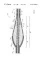
- FIG. 6illustrates yet another alternative embodiment of a drive shaft 220 for use in a rotational atherectomy device in accordance with the present invention.
- like reference numbersare used to refer to parts which perform substantially the same function as parts of the drive shaft 20 shown in FIG. 2, with the addition of 200 to the reference numbers.
- FIGS. 2 and 4both show drive shafts wherein the wire turns of their respective proximal portions 32 of their enlarged diameter segments 30 and 30 ′ have diameters which gradually increase distally at a generally constant rate, each forming generally the shape of a cone.
- the wire turns of the distal portions 34 and 34 ′form a generally convex, almost parabolic outer shapes, yielding asymmetrical profiles of the enlarged diameter segments 30 and 30 ′.
- the proximal portion 232 of the enlarged diameter segment 230need not have the aforementioned conical shape in order to flex properly in use.
- the drive shaft 220 of FIG. 6when bent still yields a smooth outer profile without the misalignment of adjacent wire turns typified in FIG. 9 .
- Each of the enlarged diameter intermediate segments 30 , 30 ′ and 130 of FIGS. 2, 4 and 8utilize an outer helical coil which is essentially bottomed out (i.e., wherein adjacent turns of the outer helical coil essentially abut against one another along the enlarged diameter intermediate segment).
- the relative spacing of the adjacent wire turns in the outer helical coil of the enlarged diameter segment 230is important to provide optimal operation of the drive shaft.
- the spacing between adjacent wire turns of the outer helical coil 250 in the proximal portion 232 of the enlarged diameter segment 230desirably gradually increases distally.
- the spacing between adjacent wire turns of the outer helical coil 250 in the distal portion 234 of the enlarged diameter segment 230desirably gradually decreases distally.
- a maximum spacing between adjacent wire turns of the outer helical coil from about 25 ⁇ m to about 30 ⁇ mhas been found to work well.
- FIG. 6The cross sectional view of FIG. 6 appears to show a plurality of distinct gaps between adjacent wire turns. It should be recognized that these wire turns are actually formed from a single helically wound wire and, therefore, there is only a single helical gap. As the spacing between adjacent wire turns of the outer helical coil gradually increases in the proximal portion 232 , the width of this helical gap gradually increases. As the spacing between adjacent wire turns of the outer helical coil gradually decreases in the distal portion 234 , the width of this helical gap gradually decreases.
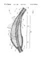
- FIG. 7shows the drive shaft 220 of FIG. 6 bent around a curve having a radius of curvature of about 10 mm.
- the wire turns of the outer helical coil 250do not fall out of alignment with each other when the enlarged diameter segment 230 of the drive shaft 220 is so bent.
- FIG. 9shows the prior art drive shaft 120 of FIG. 8 bent around a similar curve.
- FIG. 9demonstrates that the adjacent wire turns of the outer helical layer 150 along the enlarged diameter segment 130 are pushed out of alignment with one another when the drive shaft 120 of FIG. 8 is bent around such curve.
- the enlarged diameter segment 130 in FIGS. 8 and 9is very similar in most respects to the enlarged diameter segment 230 of FIGS. 6 and 7, except that the outer helical coil 150 of FIGS. 8 and 9 does not have the spacing employed in the outer helical coil 250 of FIGS. 6 and 7.
- the spacing between adjacent wire turns of the outer helical coilallows adjacent wire turns on the bottom of the enlarged diameter segment 230 (i.e., the side of the enlarged diameter segment having the smaller radius of curvature) to move toward one another while adjacent wire turns on the top of the enlarged diameter segment 230 (i.e., the side of the enlarged diameter segment having the larger radius of curvature) move farther apart from one another.
- FIG. 7demonstrates that sufficient spacing between adjacent turns of the outer helical coil 250 helps maintain the smooth profile of the enlarged diameter segment 230 even when this segment 230 is bent.
- the drive shafts 20 and 20 ′ of FIGS. 2 and 4have an inner helical coil 40 which, along the enlarged diameter segment 30 , has a helical gap 46 defined by adjacent turns of the wire group 44 .
- Such a helical gap between adjacent turns of the wire group 244is not necessary in the drive shaft 220 illustrated in FIGS. 6 and 7. Instead, the adjacent turns of the wire group 244 in the inner helical coil 240 are maintained essentially bottomed out along the entire length of the enlarged diameter segment 230 .
- FIG. 11schematically illustrates a build-up of atheromatous material 2 along the lumen of a patient's artery 4 .
- the enlarged diameter segment 230 of the drive shaft 220(originally shown in FIG. 6) is shown in FIG. 11 in contact with the atheromatous material 2 so that the abrasive material of the distal portion 234 can abrade the atheromatous material.
- the abrasive portion of the devicetypically precludes the flow of blood therethrough.
- a solid burris utilized in prior art drive shaft 120 shown in FIGS. 8 and 9 of the present application.
- the abutment of each of the wires against one another in the enlarged diameter segmentwill also effectively preclude the flow of fluids through the outer helical coil 150 in this segment. Accordingly, there is no ready path provided to permit blood in the artery 4 to flow from a position proximal of the enlarged diameter segment 130 to the other side of the atheromatous build-up while the device is in use.
- FIG. 11illustrates another advantage of the drive shaft 220 illustrated in FIG. 6 .
- the drive shaft 220permits blood or other fluids to flow through the enlarged diameter segment 230 .
- This blood flowis schematically illustrated by arrows.
- the drawing in FIG. 11has been simplified by omitting the abrasive material 238 as well as some of the lines representing the turns of the outer helical coil 250 .
- fluidcan flow through the gaps between adjacent turns of the outer helical coil 250 in the proximal portion 232 of the enlarged diameter segment.
- the fluid entering the enlarged diameter segmentmay then pass through the gaps between adjacent turns of the outer helical coil 250 in the distal portion 234 of the enlarged diameter segment, defining a path for fluid flow through the enlarged diameter segment.
- the drive shafts illustrated in Shturman's U.S. Pat. No. 5,314,438include gaps in the enlarged diameter segments to facilitate ultrasound imaging (see, e.g., FIGS. 9-22 of that patent).
- the ultrasound imaging gapis only provided between two adjacent turns of the helical coil and, thus, the gap extends only for about a single turn of the helical coil.
- the gapis positioned generally along the middle of the enlarged diameter segment.
- the gaphas a length equal to the length of essentially all turns of the outer helical coil 250 along the enlarged diameter segment.
- This long gapappears to present multiple gaps in the cross sectional view of FIG. 11.
- the long gapgreatly improves fluid flow through the enlarged diameter segment 230 .
- This fluid flowis advantageous for at least two reasons. First, it can allow blood to flow through the region being treated, allowing the operator to treat the underlying stenosis without having to block the flow of blood to anatomical structures supplied by the artery being treated and located downstream of the stenosis. Second, fluids passing through the enlarged diameter segment 230 will serve as both a cooling medium and a lubricant, helping minimize any heat which may build up due to the friction between the enlarged diameter segment 230 and the atheromatous material 2 .
- FIGS. 12 and 13illustrate another alternative embodiment of the invention.
- This drive shaft 220 ′is very similar to the drive shaft 220 illustrated In FIGS. 6 and 7.
- the drive shaft 220includes both an outer helical coil 250 and an inner helical coil 240 , as detailed above.
- the drive shaft 220 ′includes only a single helical coil 250 ′.
- This helical 0 coil 250 ′is desirably formed of a single wire, i.e., this coil is desirably a mono-filar coil.
- this coilis desirably a mono-filar coil.
- the proximal portion 232 ′ of the enlarged diameter segment 230 ′has wire turns which have diameters that gradually increase distally and spaces between adjacent wire turns which gradually increase distally.
- the distal segment 234 ′has wire turns which have diameters that gradually decrease distally and spaces between adjacent wire turns which gradually decrease distally through the distal portion 234 ′.
- the drive shaft 220 ′ in FIGS. 12 and 13includes only a single coil 250 ′.
- the other advantages outlined above in connection with the earlier drive shaft 220would continue to apply with respect to this modified design 220 ′.
- the enlarged diameter segment 230 ′can be curved through an arc with minimal chance of having adjacent wire turns slip out of alignment with one another. (Compare FIG. 13 with the prior art device illustrated in FIG. 9.) Additionally, fluid can flow relatively freely through the enlarged diameter segment 230 ′ in much the same fashion as discussed above in connection with the enlarged diameter segment 230 shown in FIG. 11 .
- FIGS. 14 and 15illustrate two possible modifications of the drive shaft 220 shown in FIG. 6. A majority of the structural features of the drive shaft 220 remain the same as those illustrated in the earlier drawing, so like reference numbers are used in FIGS. 14 and 15.
- the drive shafts shown In FIGS. 14 and 15differ from the drive shaft of FIG. 6 primarily in that these later embodiments incorporate imaging elements for use in ultrasound imaging techniques.
- this drive shaftincludes at least one ultrasound transducer element 260 , and desirably includes a plurality of such elements arranged in diametrically opposed pairs spaced generally circumferentially within the enlarged diameter segment 230 .
- these ultrasound transducer elementscan be positioned essentially anywhere within the drive shaft, it is believed best to place them with at least a portion of the length of the transducer element 260 positioned generally radially inwardly of a space between adjacent wire turns of the outer helical coil. This will help ensure that the wire of the outer helical coil will not interfere with the ultrasonic waves emitted by the transducers (schematically illustrated as dotted lines extending outwardly from the enlarged diameter segment).
- these ultrasonic transducer elements 260can be held at the desired position within the enlarged diameter segment 230 simply by embedding them in a flexible bushing 270 .
- the bushinghas a smaller diameter along most of its length than the inner diameter of the outer helical coil 250 . Maintaining a space between the bushing and the outer helical coil will help maximize the flexibility of the enlarged diameter segment 230 by minimizing the impact of the bushing on movement of the wire turns of the outer helical coil 250 with respect to one another.
- the bushingmay be formed of any suitable sonolucent material, i.e., a material which is relatively transparent to ultrasound waves and minimally reflects or attenuates ultrasonic energy. In order to maximize the flexibility of the enlarged diameter segment, the material of the bushing is optimally highly flexible, as well. Material such as silicone, latex and certain other plastics (e.g., polyethylene) are believed to be suitable for such a sonolucent bushing 270 .
- the proximal segment 222 of the drive shaft shown in FIG. 14has been modified slightly from the design shown in FIG. 6 .
- the adjacent wire turns of the outer helical coil 250 in this proximal segment 222are not bottomed out in the embodiment shown in FIG. 14 .
- a generally helical gap 256is defined by adjacent turns of the wire forming the outer helical coil.
- Electrodes 264 attached to the transducer elementscan then be received within this generally helical gap 256 between adjacent turns of the wire forming the outer helical coil 250 . This permits the leads to extend proximally out of the patient's body for connection to an ultrasound imaging machine (not shown). If so desired, a sheath 223 may be provided along some or all of the proximal segment 222 of the drive shaft.
- the bushing 270 ′ of the drive shaft 220 shown in FIG. 15substantially fills the space between the exterior of the inner helical coil 240 and the interior surface of the outer helical coil 250 throughout the entire enlarged diameter segment 230 .
- This larger bushing 270 ′may be formed of the same materials discussed above for the bushing 270 .
- This bushingmay also serve to bond the inner helical coil 240 and outer helical coil 250 in much the same fashion as the bonds 236 in FIG. 14 .
- a distal bond 236is illustrated in FIG. 15 to indicate that at least one of these bonds could remain. In most instances, though, the bushing 270 ′ will likely obviate the need to include such a bond 236 .
- the drive shaft 220 shown in FIG. 15also includes at least one signal processor 262 , and preferably includes a plurality of such processors 262 , as shown. These processors may be positioned distally of the transducer elements 260 ′ and may be positioned closer to the inner helical coil 240 than are the transducer elements 260 ′. These processors receive the signals from the transducer elements and relay these signals back to the ultrasound imaging machine (not shown) by means of the leads 264 . For purposes of clarity, leads between the transducer elements 260 ′ and the processors 262 are not shown in FIG. 15, but it is to be understood that these transducer elements are connected to the processors.
- the processors 262may comprise little more than amplifiers to boost the signal received from the transducer elements 260 ′. These processors could also perform at least some rudimentary signal processing before delivering the signal to the ultrasound imaging machine through the leads. Such processors are known in the art and are already incorporated into some commercially available ultrasound imaging catheters.
- FIG. 16illustrates another embodiment of the invention. This embodiment illustrates a useful modification of the proximal segment 222 of the drive shaft 220 shown in FIG. 6 . It is to be understood, though, that the modification of the drive shaft illustrated in FIG. 16 could be used to equal advantage in any of the other embodiments of the invention discussed above.
- the drive shaft of FIG. 16has the same basic structure as the dual-coil drive shafts discussed above.
- the drive shaftgenerally includes an inner helical coil 240 received within a lumen of an outer helical coil 250 .
- These inner and outer wire layersare desirably helically wound in opposite directions so that the outer layer tends to radially contract and the inner layer tends to radially expand when the drive shaft is rotated in a predetermined direction by the driver 15 .
- the inner helical coilmay be multi-filar while the outer helical coil is a mono-filar coil, but that may not be necessary in connection with the present embodiment.
- the present drive shaftprovides a generally helical gap 16 between adjacent turns of the outer helical coil 250 along at least a portion of the proximal segment 222 .
- this helical gap 16extends along a majority of the length of the catheter 13 within which the drive shaft is received.
- this gap 16desirably extends from a position outside the patient's body to a position located distally close to or even beyond the distal end of the catheter 13 .
- a fluid source 17is provided in fluid communication with the lumen of the catheter 13 outside the patient's body.
- the fluid sourcemay provide, for example, a saline solution or a radiographic contrast medium. This fluid flowing within the catheter will serve to both lubricate and cool the system, minimizing any problems due to friction between the drive shaft and the catheter when the drive shaft is rotated at high speeds.
- the helical gap 16 in the outer helical coil 250serves to urge fluid from the fluid source 17 distally along the catheter 13 .
- the lumen of the catheter 13is desirably somewhat larger than the outer diameter of the outer helical coil 250 when the drive shaft is rotated. Accordingly, there is no clear helical space defined within the catheter to pump fluids. Nonetheless, the rotation of the gap 16 as the drive shaft is rotated will help induce a distal fluid flow within the catheter.
- FIG. 16is the illustration of gaps between adjacent turns of the wire or wires of the inner helical coil 240 .
- the inner helical coilbe formed so that it is essentially bottomed out along the proximal segment of the drive shaft.
- a “bottomed out” coil formed on a mandrelwill tend to have adjacent turns of the wire separated slightly from one another.
- the size of the gaps between adjacent turns of the inner helical coilis exaggerated in FIG. 16, these gaps are substantially smaller than the helical gap 16 in the outer helical coil, permitting the drive shaft to pump fluid relatively effectively.
Landscapes
- Health & Medical Sciences (AREA)
- Surgery (AREA)
- Life Sciences & Earth Sciences (AREA)
- Medical Informatics (AREA)
- Nuclear Medicine, Radiotherapy & Molecular Imaging (AREA)
- Engineering & Computer Science (AREA)
- Biomedical Technology (AREA)
- Heart & Thoracic Surgery (AREA)
- Vascular Medicine (AREA)
- Molecular Biology (AREA)
- Animal Behavior & Ethology (AREA)
- General Health & Medical Sciences (AREA)
- Public Health (AREA)
- Veterinary Medicine (AREA)
- Surgical Instruments (AREA)
- Media Introduction/Drainage Providing Device (AREA)
Abstract
Description
Claims (26)
Priority Applications (1)
| Application Number | Priority Date | Filing Date | Title |
|---|---|---|---|
| US09/225,370US6217595B1 (en) | 1996-11-18 | 1999-01-04 | Rotational atherectomy device |
Applications Claiming Priority (2)
| Application Number | Priority Date | Filing Date | Title |
|---|---|---|---|
| US75164296A | 1996-11-18 | 1996-11-18 | |
| US09/225,370US6217595B1 (en) | 1996-11-18 | 1999-01-04 | Rotational atherectomy device |
Related Parent Applications (1)
| Application Number | Title | Priority Date | Filing Date |
|---|---|---|---|
| US75164296ADivision | 1996-11-18 | 1996-11-18 |
Publications (1)
| Publication Number | Publication Date |
|---|---|
| US6217595B1true US6217595B1 (en) | 2001-04-17 |
Family
ID=25022875
Family Applications (1)
| Application Number | Title | Priority Date | Filing Date |
|---|---|---|---|
| US09/225,370Expired - LifetimeUS6217595B1 (en) | 1996-11-18 | 1999-01-04 | Rotational atherectomy device |
Country Status (1)
| Country | Link |
|---|---|
| US (1) | US6217595B1 (en) |
Cited By (98)
| Publication number | Priority date | Publication date | Assignee | Title |
|---|---|---|---|---|
| US20020165567A1 (en)* | 1999-02-02 | 2002-11-07 | Samuel Shiber | Vessel cleaner |
| US20030139689A1 (en)* | 2001-11-19 | 2003-07-24 | Leonid Shturman | High torque, low profile intravascular guidewire system |
| US6602264B1 (en) | 1997-07-24 | 2003-08-05 | Rex Medical, L.P. | Rotational thrombectomy apparatus and method with standing wave |
| US20030191483A1 (en)* | 2002-04-04 | 2003-10-09 | Rex Medical | Thrombectomy device with multi-layered rotational wire |
| US6669662B1 (en)* | 2000-12-27 | 2003-12-30 | Advanced Cardiovascular Systems, Inc. | Perfusion catheter |
| EP1350473A3 (en)* | 2002-04-01 | 2004-10-06 | Rex Medical, L.P. | Thrombectomy apparatus |
| WO2004098692A1 (en)* | 2003-05-09 | 2004-11-18 | Angiomed Gmbh & Co. Medizintechnik Kg | Strain management in stent delivery system |
| US20050090849A1 (en)* | 2003-10-22 | 2005-04-28 | Adams Kenneth M. | Angled tissue cutting instruments and method of fabricating angled tissue cutting instrument having flexible inner tubular members of tube and single wrap construction |
| US20050090848A1 (en)* | 2003-10-22 | 2005-04-28 | Adams Kenneth M. | Angled tissue cutting instruments and method of fabricating angled tissue cutting instruments having flexible inner tubular members of tube and sleeve construction |
| US20060106407A1 (en)* | 2004-11-17 | 2006-05-18 | Mcguckin James F Jr | Rotational thrombectomy wire |
| US20060229659A1 (en)* | 2004-12-09 | 2006-10-12 | The Foundry, Inc. | Aortic valve repair |
| US20070049847A1 (en)* | 2005-08-05 | 2007-03-01 | Cook Incorporated | High performance wire guide |
| US20080065124A1 (en)* | 1999-08-19 | 2008-03-13 | Foxhollow Technologies, Inc. | High capacity debulking catheter with razor edge cutting window |
| US20090105736A1 (en)* | 2007-10-23 | 2009-04-23 | Cardiovascular Systems, Inc. | Rotational atherectomy device with counterweighting |
| US20090216180A1 (en)* | 2008-02-25 | 2009-08-27 | Fox Hollow Technologies, Inc. | Methods and devices for cutting tissue |
| US20090264908A1 (en)* | 2008-04-18 | 2009-10-22 | Cardiovascular Systems, Inc. | Method and apparatus for increasing rotational amplitude of abrasive element on high-speed rotational atherectomy device |
| US20090275966A1 (en)* | 2008-05-05 | 2009-11-05 | Miroslav Mitusina | Flexible inner members having flexible regions comprising a plurality of intertwined helical cuts |
| US20090306587A1 (en)* | 2005-06-20 | 2009-12-10 | Zoran Milijasevic | Sleeve Steering and Reinforcement |
| US7645261B2 (en) | 1999-10-22 | 2010-01-12 | Rex Medical, L.P | Double balloon thrombectomy catheter |
| US20100100110A1 (en)* | 2008-05-30 | 2010-04-22 | Cardiovascular Systems, Inc. | Eccentric abrading and cutting head for high-speed rotational atherectomy devices |
| US20100312263A1 (en)* | 2009-04-29 | 2010-12-09 | Fox Hollow Technologies, Inc. | Methods and devices for cutting and abrading tissue |
| US8192452B2 (en) | 2009-05-14 | 2012-06-05 | Tyco Healthcare Group Lp | Easily cleaned atherectomy catheters and methods of use |
| US8226674B2 (en) | 2000-12-20 | 2012-07-24 | Tyco Healthcare Group Lp | Debulking catheters and methods |
| US8246640B2 (en) | 2003-04-22 | 2012-08-21 | Tyco Healthcare Group Lp | Methods and devices for cutting tissue at a vascular location |
| US8414604B2 (en) | 2008-10-13 | 2013-04-09 | Covidien Lp | Devices and methods for manipulating a catheter shaft |
| US8414543B2 (en) | 1999-10-22 | 2013-04-09 | Rex Medical, L.P. | Rotational thrombectomy wire with blocking device |
| US8469979B2 (en) | 2000-12-20 | 2013-06-25 | Covidien Lp | High capacity debulking catheter with distal driven cutting wheel |
| US8496677B2 (en) | 2009-12-02 | 2013-07-30 | Covidien Lp | Methods and devices for cutting tissue |
| US8597315B2 (en) | 1999-08-19 | 2013-12-03 | Covidien Lp | Atherectomy catheter with first and second imaging devices |
| US8663259B2 (en) | 2010-05-13 | 2014-03-04 | Rex Medical L.P. | Rotational thrombectomy wire |
| US8764779B2 (en) | 2010-05-13 | 2014-07-01 | Rex Medical, L.P. | Rotational thrombectomy wire |
| US8808186B2 (en) | 2010-11-11 | 2014-08-19 | Covidien Lp | Flexible debulking catheters with imaging and methods of use and manufacture |
| US8920450B2 (en) | 2010-10-28 | 2014-12-30 | Covidien Lp | Material removal device and method of use |
| WO2014210458A1 (en)* | 2013-06-28 | 2014-12-31 | Cardiovascular Systems, Inc. | Atherectomy device having combined open/close drive shaft |
| WO2015013590A1 (en) | 2013-07-26 | 2015-01-29 | Cardiovascular Systems, Inc. | Devices, systems and methods for performing atherectomy and subsequent balloon angioplasty without exchanging devices |
| US8992717B2 (en) | 2011-09-01 | 2015-03-31 | Covidien Lp | Catheter with helical drive shaft and methods of manufacture |
| US8998937B2 (en) | 1999-08-19 | 2015-04-07 | Covidien Lp | Methods and devices for cutting tissue |
| US9023070B2 (en) | 2010-05-13 | 2015-05-05 | Rex Medical, L.P. | Rotational thrombectomy wire coupler |
| US9028512B2 (en) | 2009-12-11 | 2015-05-12 | Covidien Lp | Material removal device having improved material capture efficiency and methods of use |
| US9034032B2 (en) | 2011-10-19 | 2015-05-19 | Twelve, Inc. | Prosthetic heart valve devices, prosthetic mitral valves and associated systems and methods |
| US9119662B2 (en) | 2010-06-14 | 2015-09-01 | Covidien Lp | Material removal device and method of use |
| US9125740B2 (en) | 2011-06-21 | 2015-09-08 | Twelve, Inc. | Prosthetic heart valve devices and associated systems and methods |
| US20150305765A1 (en)* | 2014-04-28 | 2015-10-29 | Distal Access, Llc | Tissue resectors with cutting wires, hand operated tissue resecting systems and associated methods |
| US9421098B2 (en) | 2010-12-23 | 2016-08-23 | Twelve, Inc. | System for mitral valve repair and replacement |
| USD766433S1 (en) | 2013-11-04 | 2016-09-13 | Cardiovascular Systems, Inc. | Eccentric crown |
| US9468457B2 (en) | 2013-09-30 | 2016-10-18 | Cardiovascular Systems, Inc. | Atherectomy device with eccentric crown |
| WO2016196530A1 (en) | 2015-06-01 | 2016-12-08 | Cardiovascular Systems, Inc. | Rotational systems comprising a polymer driveshaft |
| US9532844B2 (en) | 2012-09-13 | 2017-01-03 | Covidien Lp | Cleaning device for medical instrument and method of use |
| US9579198B2 (en) | 2012-03-01 | 2017-02-28 | Twelve, Inc. | Hydraulic delivery systems for prosthetic heart valve devices and associated methods |
| US9629646B2 (en) | 2012-07-11 | 2017-04-25 | Jens Kather | Curved burr surgical instrument |
| US9655722B2 (en) | 2011-10-19 | 2017-05-23 | Twelve, Inc. | Prosthetic heart valve devices, prosthetic mitral valves and associated systems and methods |
| CN107073244A (en)* | 2014-10-20 | 2017-08-18 | 美敦力 | Centralized positioning coil form guiding piece |
| WO2017147402A1 (en) | 2016-02-26 | 2017-08-31 | Cardiovascular Systems, Inc. | Powerline communication systems and methods for medical devices |
| US9763780B2 (en) | 2011-10-19 | 2017-09-19 | Twelve, Inc. | Devices, systems and methods for heart valve replacement |
| US9795406B2 (en) | 2010-05-13 | 2017-10-24 | Rex Medical, L.P. | Rotational thrombectomy wire |
| US9801647B2 (en) | 2006-05-26 | 2017-10-31 | Covidien Lp | Catheter including cutting element and energy emitting element |
| US9855070B2 (en) | 2014-03-12 | 2018-01-02 | Boston Scientific Limited | Infusion lubricated atherectomy catheter |
| WO2018017525A1 (en) | 2016-07-19 | 2018-01-25 | Cardiovascular Systems, Inc. | Rotational medical device with airfoil |
| US9883886B2 (en)* | 2007-11-23 | 2018-02-06 | Cardio Flow, Inc. | Rotational atherectomy system |
| US9901443B2 (en) | 2011-10-19 | 2018-02-27 | Twelve, Inc. | Prosthetic heart valve devices, prosthetic mitral valves and associated systems and methods |
| US9943329B2 (en) | 2012-11-08 | 2018-04-17 | Covidien Lp | Tissue-removing catheter with rotatable cutter |
| US10052122B2 (en) | 2014-01-17 | 2018-08-21 | Cardiovascular Systems, Inc. | Spin-to-open atherectomy device with electric motor control |
| US10111747B2 (en) | 2013-05-20 | 2018-10-30 | Twelve, Inc. | Implantable heart valve devices, mitral valve repair devices and associated systems and methods |
| US10213224B2 (en) | 2014-06-27 | 2019-02-26 | Covidien Lp | Cleaning device for catheter and catheter including the same |
| US10238490B2 (en) | 2015-08-21 | 2019-03-26 | Twelve, Inc. | Implant heart valve devices, mitral valve repair devices and associated systems and methods |
| US10265172B2 (en) | 2016-04-29 | 2019-04-23 | Medtronic Vascular, Inc. | Prosthetic heart valve devices with tethered anchors and associated systems and methods |
| US10292721B2 (en) | 2015-07-20 | 2019-05-21 | Covidien Lp | Tissue-removing catheter including movable distal tip |
| US10314667B2 (en) | 2015-03-25 | 2019-06-11 | Covidien Lp | Cleaning device for cleaning medical instrument |
| US10314664B2 (en) | 2015-10-07 | 2019-06-11 | Covidien Lp | Tissue-removing catheter and tissue-removing element with depth stop |
| US10335042B2 (en) | 2013-06-28 | 2019-07-02 | Cardiovascular Systems, Inc. | Methods, devices and systems for sensing, measuring and/or characterizing vessel and/or lesion compliance and/or elastance changes during vascular procedures |
| US10405878B2 (en) | 2014-07-25 | 2019-09-10 | Boston Scientific Scimed, Inc. | Rotatable medical device |
| US10405879B2 (en) | 2014-12-04 | 2019-09-10 | Boston Scientific Scimed, Inc. | Rotatable medical device |
| EP3413814A4 (en)* | 2016-02-08 | 2019-10-02 | Teleflex Medical Incorporated | ROTATING MECHANICAL THROMBECTOMY DEVICE |
| US10433961B2 (en) | 2017-04-18 | 2019-10-08 | Twelve, Inc. | Delivery systems with tethers for prosthetic heart valve devices and associated methods |
| US10524826B1 (en) | 2018-06-14 | 2020-01-07 | Cardio Flow, Inc. | Atherectomy devices and methods |
| US10575950B2 (en) | 2017-04-18 | 2020-03-03 | Twelve, Inc. | Hydraulic systems for delivering prosthetic heart valve devices and associated methods |
| US10646338B2 (en) | 2017-06-02 | 2020-05-12 | Twelve, Inc. | Delivery systems with telescoping capsules for deploying prosthetic heart valve devices and associated methods |
| US10702380B2 (en) | 2011-10-19 | 2020-07-07 | Twelve, Inc. | Devices, systems and methods for heart valve replacement |
| US10702378B2 (en) | 2017-04-18 | 2020-07-07 | Twelve, Inc. | Prosthetic heart valve device and associated systems and methods |
| US10709591B2 (en) | 2017-06-06 | 2020-07-14 | Twelve, Inc. | Crimping device and method for loading stents and prosthetic heart valves |
| US10729541B2 (en) | 2017-07-06 | 2020-08-04 | Twelve, Inc. | Prosthetic heart valve devices and associated systems and methods |
| US10786352B2 (en) | 2017-07-06 | 2020-09-29 | Twelve, Inc. | Prosthetic heart valve devices and associated systems and methods |
| US10792151B2 (en) | 2017-05-11 | 2020-10-06 | Twelve, Inc. | Delivery systems for delivering prosthetic heart valve devices and associated methods |
| US10869689B2 (en) | 2017-05-03 | 2020-12-22 | Medtronic Vascular, Inc. | Tissue-removing catheter |
| CN112237463A (en)* | 2020-09-21 | 2021-01-19 | 上海微创医疗器械(集团)有限公司 | Rotary grinding catheter |
| US11000307B2 (en) | 2010-10-19 | 2021-05-11 | Minerva Surgical Inc. | Apparatus for rotating medical devices, systems including the apparatus, and associated methods |
| US11202704B2 (en) | 2011-10-19 | 2021-12-21 | Twelve, Inc. | Prosthetic heart valve devices, prosthetic mitral valves and associated systems and methods |
| US11272954B2 (en) | 2018-08-07 | 2022-03-15 | Cardio Flow, Inc. | Atherectomy devices and methods |
| US11357534B2 (en) | 2018-11-16 | 2022-06-14 | Medtronic Vascular, Inc. | Catheter |
| US11446050B2 (en) | 2014-04-28 | 2022-09-20 | Minerva Surgical, Inc. | Tissue resectors with cutting wires, hand operated tissue resecting systems and associated methods |
| US20220330971A1 (en)* | 2019-09-27 | 2022-10-20 | Shanghai Microport Rhythm Medtech Co., Ltd. | Rotation device, and drive shaft for rotation device |
| US11690645B2 (en) | 2017-05-03 | 2023-07-04 | Medtronic Vascular, Inc. | Tissue-removing catheter |
| CN117064493A (en)* | 2023-10-17 | 2023-11-17 | 广东博迈医疗科技股份有限公司 | Eccentric thrombus grinds subassembly soon and grinds system soon |
| US11819236B2 (en) | 2019-05-17 | 2023-11-21 | Medtronic Vascular, Inc. | Tissue-removing catheter |
| US20240115289A1 (en)* | 2022-10-06 | 2024-04-11 | Cardiovascular Systems, Inc. | Rotational drive shafts and intravascular medical devices thereof |
| US12004771B1 (en) | 2023-06-27 | 2024-06-11 | Cardio Flow, Inc. | Rotational atherectomy devices and methods |
| EP4509070A2 (en) | 2015-02-20 | 2025-02-19 | Cardiovascular Systems, Inc. | Methods and systems for disrupting calcified walls of biological conduits and calcified lesions therein |
| US12440237B2 (en) | 2025-05-16 | 2025-10-14 | Cardio Flow, Inc. | Rotational atherectomy devices and methods |
Citations (41)
| Publication number | Priority date | Publication date | Assignee | Title |
|---|---|---|---|---|
| US1481078A (en) | 1922-11-24 | 1924-01-15 | Albertson & Company | Flexible shafting |
| US1636038A (en) | 1926-03-18 | 1927-07-19 | Bolozky Samuel | Fan installation |
| US1785345A (en) | 1928-05-19 | 1930-12-16 | American Flexible Shaft Mfg Co | Casing for flexible shafts |
| US2570335A (en) | 1949-03-25 | 1951-10-09 | Morris Farm Machinery Company | Flexible shaft |
| US2761297A (en) | 1953-10-19 | 1956-09-04 | Buchsteiner Josef | Flexible shaft construction |
| US2821092A (en) | 1956-08-16 | 1958-01-28 | Teleflex Inc | Control system and conduit cable |
| US3180625A (en) | 1963-07-23 | 1965-04-27 | Wyco Tool Co | Power transmission means for concrete vibrator |
| US3937222A (en) | 1973-11-09 | 1976-02-10 | Surgical Design Corporation | Surgical instrument employing cutter means |
| US4112708A (en) | 1976-06-21 | 1978-09-12 | Nippon Cable Systems Inc. | Flexible drive cable |
| US4424045A (en) | 1982-05-24 | 1984-01-03 | Pennwalt Corporation | Rigid high speed flexible shaft casing assembly for tight radii installations |
| US4445509A (en) | 1982-02-04 | 1984-05-01 | Auth David C | Method and apparatus for removal of enclosed abnormal deposits |
| EP0191630A2 (en) | 1985-02-13 | 1986-08-20 | Kensey Nash Corporation | Catheter with high speed drive means |
| US4607626A (en) | 1984-06-18 | 1986-08-26 | German Borodulin | Expandable urethral bougie comprising bendable rods with reciprocating driver |
| US4646736A (en) | 1984-09-10 | 1987-03-03 | E. R. Squibb & Sons, Inc. | Transluminal thrombectomy apparatus |
| US4664112A (en) | 1985-08-12 | 1987-05-12 | Intravascular Surgical Instruments, Inc. | Catheter based surgical methods and apparatus therefor |
| US4686982A (en) | 1985-06-19 | 1987-08-18 | John Nash | Spiral wire bearing for rotating wire drive catheter |
| US4700706A (en) | 1984-03-28 | 1987-10-20 | Muench Walter | Cold and warm pack for physiotherapy and the like |
| US4704121A (en) | 1983-09-28 | 1987-11-03 | Nimbus, Inc. | Anti-thrombogenic blood pump |
| EP0268228A2 (en) | 1986-11-14 | 1988-05-25 | Heart Technology, Inc. | Clinically practical rotational angioplasty systems |
| US4811735A (en) | 1987-07-30 | 1989-03-14 | Kensey Nash Corporation | Stone destroying catheter and method of use |
| US4976689A (en) | 1984-09-18 | 1990-12-11 | Medtronic Versaflex, Inc. | Outer exchange catheter system |
| US4990134A (en) | 1986-01-06 | 1991-02-05 | Heart Technology, Inc. | Transluminal microdissection device |
| US5158564A (en) | 1990-02-14 | 1992-10-27 | Angiomed Ag | Atherectomy apparatus |
| US5192291A (en) | 1992-01-13 | 1993-03-09 | Interventional Technologies, Inc. | Rotationally expandable atherectomy cutter assembly |
| US5217474A (en) | 1991-07-15 | 1993-06-08 | Zacca Nadim M | Expandable tip atherectomy method and apparatus |
| US5246420A (en) | 1990-11-19 | 1993-09-21 | Danforth Biomedical Incorporated | Highly steerable dilatation balloon catheter system |
| US5273052A (en) | 1992-01-08 | 1993-12-28 | Danforth Biomedical, Incorporated | Guidewire with reversible contact seal for releasable securement to catheter |
| US5312427A (en) | 1992-10-16 | 1994-05-17 | Shturman Cardiology Systems, Inc. | Device and method for directional rotational atherectomy |
| US5314438A (en) | 1992-12-17 | 1994-05-24 | Shturman Cardiology Systems, Inc. | Abrasive drive shaft device for rotational atherectomy |
| US5314407A (en) | 1986-11-14 | 1994-05-24 | Heart Technology, Inc. | Clinically practical rotational angioplasty system |
| US5318576A (en)* | 1992-12-16 | 1994-06-07 | Plassche Jr Walter M | Endovascular surgery systems |
| US5356418A (en) | 1992-10-28 | 1994-10-18 | Shturman Cardiology Systems, Inc. | Apparatus and method for rotational atherectomy |
| US5358485A (en) | 1992-01-13 | 1994-10-25 | Schneider (Usa) Inc. | Cutter for atherectomy catheter |
| US5395311A (en) | 1990-05-14 | 1995-03-07 | Andrews; Winston A. | Atherectomy catheter |
| US5490859A (en) | 1992-11-13 | 1996-02-13 | Scimed Life Systems, Inc. | Expandable intravascular occlusion material removal devices and methods of use |
| RU2055991C1 (en) | 1995-02-21 | 1996-03-10 | Гуськов Игорь Алексеевич | Turbine for driving hand tools |
| US5501694A (en) | 1992-11-13 | 1996-03-26 | Scimed Life Systems, Inc. | Expandable intravascular occlusion material removal devices and methods of use |
| US5584843A (en) | 1994-12-20 | 1996-12-17 | Boston Scientific Corporation | Shaped wire multi-burr rotational ablation device |
| WO1997009924A1 (en) | 1995-09-14 | 1997-03-20 | Shturman Cardiology Systems, Inc. | Rotatable intravascular apparatus |
| WO1998002101A1 (en) | 1996-07-15 | 1998-01-22 | Shturman Cardiology Systems, Inc. | Rotational atherectomy device |
| US5766190A (en)* | 1995-05-24 | 1998-06-16 | Boston Scientific Corporation Northwest Technology Center, Inc. | Connectable driveshaft system |
- 1999
- 1999-01-04USUS09/225,370patent/US6217595B1/ennot_activeExpired - Lifetime
Patent Citations (44)
| Publication number | Priority date | Publication date | Assignee | Title |
|---|---|---|---|---|
| US1481078A (en) | 1922-11-24 | 1924-01-15 | Albertson & Company | Flexible shafting |
| US1636038A (en) | 1926-03-18 | 1927-07-19 | Bolozky Samuel | Fan installation |
| US1785345A (en) | 1928-05-19 | 1930-12-16 | American Flexible Shaft Mfg Co | Casing for flexible shafts |
| US2570335A (en) | 1949-03-25 | 1951-10-09 | Morris Farm Machinery Company | Flexible shaft |
| US2761297A (en) | 1953-10-19 | 1956-09-04 | Buchsteiner Josef | Flexible shaft construction |
| US2821092A (en) | 1956-08-16 | 1958-01-28 | Teleflex Inc | Control system and conduit cable |
| US3180625A (en) | 1963-07-23 | 1965-04-27 | Wyco Tool Co | Power transmission means for concrete vibrator |
| US3937222A (en) | 1973-11-09 | 1976-02-10 | Surgical Design Corporation | Surgical instrument employing cutter means |
| US4112708A (en) | 1976-06-21 | 1978-09-12 | Nippon Cable Systems Inc. | Flexible drive cable |
| US4445509A (en) | 1982-02-04 | 1984-05-01 | Auth David C | Method and apparatus for removal of enclosed abnormal deposits |
| US4424045A (en) | 1982-05-24 | 1984-01-03 | Pennwalt Corporation | Rigid high speed flexible shaft casing assembly for tight radii installations |
| US4704121A (en) | 1983-09-28 | 1987-11-03 | Nimbus, Inc. | Anti-thrombogenic blood pump |
| US4700706A (en) | 1984-03-28 | 1987-10-20 | Muench Walter | Cold and warm pack for physiotherapy and the like |
| US4607626A (en) | 1984-06-18 | 1986-08-26 | German Borodulin | Expandable urethral bougie comprising bendable rods with reciprocating driver |
| US4646736A (en) | 1984-09-10 | 1987-03-03 | E. R. Squibb & Sons, Inc. | Transluminal thrombectomy apparatus |
| US4976689A (en) | 1984-09-18 | 1990-12-11 | Medtronic Versaflex, Inc. | Outer exchange catheter system |
| EP0191630A2 (en) | 1985-02-13 | 1986-08-20 | Kensey Nash Corporation | Catheter with high speed drive means |
| US4686982A (en) | 1985-06-19 | 1987-08-18 | John Nash | Spiral wire bearing for rotating wire drive catheter |
| US4664112A (en) | 1985-08-12 | 1987-05-12 | Intravascular Surgical Instruments, Inc. | Catheter based surgical methods and apparatus therefor |
| US4990134A (en) | 1986-01-06 | 1991-02-05 | Heart Technology, Inc. | Transluminal microdissection device |
| US4990134B1 (en) | 1986-01-06 | 1996-11-05 | Heart Techn Inc | Transluminal microdissection device |
| US5314407A (en) | 1986-11-14 | 1994-05-24 | Heart Technology, Inc. | Clinically practical rotational angioplasty system |
| EP0268228A2 (en) | 1986-11-14 | 1988-05-25 | Heart Technology, Inc. | Clinically practical rotational angioplasty systems |
| US4811735A (en) | 1987-07-30 | 1989-03-14 | Kensey Nash Corporation | Stone destroying catheter and method of use |
| US5158564A (en) | 1990-02-14 | 1992-10-27 | Angiomed Ag | Atherectomy apparatus |
| US5395311A (en) | 1990-05-14 | 1995-03-07 | Andrews; Winston A. | Atherectomy catheter |
| US5246420A (en) | 1990-11-19 | 1993-09-21 | Danforth Biomedical Incorporated | Highly steerable dilatation balloon catheter system |
| US5308354A (en) | 1991-07-15 | 1994-05-03 | Zacca Nadim M | Atherectomy and angioplasty method and apparatus |
| US5217474A (en) | 1991-07-15 | 1993-06-08 | Zacca Nadim M | Expandable tip atherectomy method and apparatus |
| US5273052A (en) | 1992-01-08 | 1993-12-28 | Danforth Biomedical, Incorporated | Guidewire with reversible contact seal for releasable securement to catheter |
| US5358485A (en) | 1992-01-13 | 1994-10-25 | Schneider (Usa) Inc. | Cutter for atherectomy catheter |
| US5192291A (en) | 1992-01-13 | 1993-03-09 | Interventional Technologies, Inc. | Rotationally expandable atherectomy cutter assembly |
| US5360432A (en) | 1992-10-16 | 1994-11-01 | Shturman Cardiology Systems, Inc. | Abrasive drive shaft device for directional rotational atherectomy |
| US5312427A (en) | 1992-10-16 | 1994-05-17 | Shturman Cardiology Systems, Inc. | Device and method for directional rotational atherectomy |
| US5356418A (en) | 1992-10-28 | 1994-10-18 | Shturman Cardiology Systems, Inc. | Apparatus and method for rotational atherectomy |
| US5501694A (en) | 1992-11-13 | 1996-03-26 | Scimed Life Systems, Inc. | Expandable intravascular occlusion material removal devices and methods of use |
| US5490859A (en) | 1992-11-13 | 1996-02-13 | Scimed Life Systems, Inc. | Expandable intravascular occlusion material removal devices and methods of use |
| US5318576A (en)* | 1992-12-16 | 1994-06-07 | Plassche Jr Walter M | Endovascular surgery systems |
| US5314438A (en) | 1992-12-17 | 1994-05-24 | Shturman Cardiology Systems, Inc. | Abrasive drive shaft device for rotational atherectomy |
| US5584843A (en) | 1994-12-20 | 1996-12-17 | Boston Scientific Corporation | Shaped wire multi-burr rotational ablation device |
| RU2055991C1 (en) | 1995-02-21 | 1996-03-10 | Гуськов Игорь Алексеевич | Turbine for driving hand tools |
| US5766190A (en)* | 1995-05-24 | 1998-06-16 | Boston Scientific Corporation Northwest Technology Center, Inc. | Connectable driveshaft system |
| WO1997009924A1 (en) | 1995-09-14 | 1997-03-20 | Shturman Cardiology Systems, Inc. | Rotatable intravascular apparatus |
| WO1998002101A1 (en) | 1996-07-15 | 1998-01-22 | Shturman Cardiology Systems, Inc. | Rotational atherectomy device |
Cited By (246)
| Publication number | Priority date | Publication date | Assignee | Title |
|---|---|---|---|---|
| US7037316B2 (en) | 1997-07-24 | 2006-05-02 | Mcguckin Jr James F | Rotational thrombectomy device |
| US7507246B2 (en) | 1997-07-24 | 2009-03-24 | Rex Medical, L.P. | Rotational thrombectomy device |
| US6602264B1 (en) | 1997-07-24 | 2003-08-05 | Rex Medical, L.P. | Rotational thrombectomy apparatus and method with standing wave |
| US20020165567A1 (en)* | 1999-02-02 | 2002-11-07 | Samuel Shiber | Vessel cleaner |
| US6758851B2 (en)* | 1999-02-02 | 2004-07-06 | Samuel Shiber | Vessel cleaner |
| US8998937B2 (en) | 1999-08-19 | 2015-04-07 | Covidien Lp | Methods and devices for cutting tissue |
| US20080065124A1 (en)* | 1999-08-19 | 2008-03-13 | Foxhollow Technologies, Inc. | High capacity debulking catheter with razor edge cutting window |
| US8328829B2 (en) | 1999-08-19 | 2012-12-11 | Covidien Lp | High capacity debulking catheter with razor edge cutting window |
| US8911459B2 (en) | 1999-08-19 | 2014-12-16 | Covidien Lp | Debulking catheters and methods |
| US8597315B2 (en) | 1999-08-19 | 2013-12-03 | Covidien Lp | Atherectomy catheter with first and second imaging devices |
| US9615850B2 (en) | 1999-08-19 | 2017-04-11 | Covidien Lp | Atherectomy catheter with aligned imager |
| US9532799B2 (en) | 1999-08-19 | 2017-01-03 | Covidien Lp | Method and devices for cutting tissue |
| US9486237B2 (en) | 1999-08-19 | 2016-11-08 | Covidien Lp | Methods and devices for cutting tissue |
| US10022145B2 (en) | 1999-08-19 | 2018-07-17 | Covidien Lp | Methods and devices for cutting tissue |
| US9788854B2 (en) | 1999-08-19 | 2017-10-17 | Covidien Lp | Debulking catheters and methods |
| US9017294B2 (en) | 1999-10-22 | 2015-04-28 | Rex Medical, L.P. | Rotational thrombectomy wire with blocking device |
| US8435218B2 (en) | 1999-10-22 | 2013-05-07 | Rex Medical, L.P. | Double balloon thrombectomy catheter |
| US8414543B2 (en) | 1999-10-22 | 2013-04-09 | Rex Medical, L.P. | Rotational thrombectomy wire with blocking device |
| US7909801B2 (en) | 1999-10-22 | 2011-03-22 | Rex Medical, L.P. | Double balloon thrombectomy catheter |
| US7645261B2 (en) | 1999-10-22 | 2010-01-12 | Rex Medical, L.P | Double balloon thrombectomy catheter |
| US8226674B2 (en) | 2000-12-20 | 2012-07-24 | Tyco Healthcare Group Lp | Debulking catheters and methods |
| US8469979B2 (en) | 2000-12-20 | 2013-06-25 | Covidien Lp | High capacity debulking catheter with distal driven cutting wheel |
| US9241733B2 (en) | 2000-12-20 | 2016-01-26 | Covidien Lp | Debulking catheter |
| US6669662B1 (en)* | 2000-12-27 | 2003-12-30 | Advanced Cardiovascular Systems, Inc. | Perfusion catheter |
| US20030139689A1 (en)* | 2001-11-19 | 2003-07-24 | Leonid Shturman | High torque, low profile intravascular guidewire system |
| EP1350473A3 (en)* | 2002-04-01 | 2004-10-06 | Rex Medical, L.P. | Thrombectomy apparatus |
| US20030191483A1 (en)* | 2002-04-04 | 2003-10-09 | Rex Medical | Thrombectomy device with multi-layered rotational wire |
| US6926725B2 (en) | 2002-04-04 | 2005-08-09 | Rex Medical, L.P. | Thrombectomy device with multi-layered rotational wire |
| US8961546B2 (en) | 2003-04-22 | 2015-02-24 | Covidien Lp | Methods and devices for cutting tissue at a vascular location |
| US9999438B2 (en) | 2003-04-22 | 2018-06-19 | Covidien Lp | Methods and devices for cutting tissue at a vascular location |
| US8246640B2 (en) | 2003-04-22 | 2012-08-21 | Tyco Healthcare Group Lp | Methods and devices for cutting tissue at a vascular location |
| US9532891B2 (en) | 2003-05-09 | 2017-01-03 | C. R. Bard, Inc. | Strain management in stent delivery system |
| US8790385B2 (en) | 2003-05-09 | 2014-07-29 | C. R. Bard, Inc. | Strain management in stent delivery system |
| US20070055338A1 (en)* | 2003-05-09 | 2007-03-08 | Jurgen Dorn | Strain management in stent delivery system |
| WO2004098692A1 (en)* | 2003-05-09 | 2004-11-18 | Angiomed Gmbh & Co. Medizintechnik Kg | Strain management in stent delivery system |
| US20050090848A1 (en)* | 2003-10-22 | 2005-04-28 | Adams Kenneth M. | Angled tissue cutting instruments and method of fabricating angled tissue cutting instruments having flexible inner tubular members of tube and sleeve construction |
| US8623266B2 (en) | 2003-10-22 | 2014-01-07 | Medtronic Xomed, Inc. | Method of fabricating angled tissue cutting instruments |
| US7338495B2 (en) | 2003-10-22 | 2008-03-04 | Medtronic Xomed, Inc. | Angled tissue cutting instruments having flexible inner tubular members of tube and sleeve construction |
| US20050090849A1 (en)* | 2003-10-22 | 2005-04-28 | Adams Kenneth M. | Angled tissue cutting instruments and method of fabricating angled tissue cutting instrument having flexible inner tubular members of tube and single wrap construction |
| US20080125799A1 (en)* | 2003-10-22 | 2008-05-29 | Adams Kenneth M | Method of fabricating angled tissue cutting instruments |
| US9474543B2 (en) | 2004-11-17 | 2016-10-25 | Argon Medical Devices, Inc. | Rotational thrombectomy wire |
| US8062317B2 (en) | 2004-11-17 | 2011-11-22 | Rex Medical, L.P. | Rotational thrombectomy wire |
| US7819887B2 (en) | 2004-11-17 | 2010-10-26 | Rex Medical, L.P. | Rotational thrombectomy wire |
| US10117671B2 (en) | 2004-11-17 | 2018-11-06 | Argon Medical Devices Inc. | Rotational thrombectomy device |
| US8465511B2 (en) | 2004-11-17 | 2013-06-18 | Rex Medical, L.P. | Rotational thrombectomy wire |
| US20060106407A1 (en)* | 2004-11-17 | 2006-05-18 | Mcguckin James F Jr | Rotational thrombectomy wire |
| US7803168B2 (en) | 2004-12-09 | 2010-09-28 | The Foundry, Llc | Aortic valve repair |
| US9414852B2 (en) | 2004-12-09 | 2016-08-16 | Twelve, Inc. | Aortic valve repair |
| US11272982B2 (en) | 2004-12-09 | 2022-03-15 | Twelve, Inc. | Intravascular treatment catheters |
| US20060229659A1 (en)* | 2004-12-09 | 2006-10-12 | The Foundry, Inc. | Aortic valve repair |
| US10350004B2 (en) | 2004-12-09 | 2019-07-16 | Twelve, Inc. | Intravascular treatment catheters |
| US20100324554A1 (en)* | 2004-12-09 | 2010-12-23 | The Foundry, Llc | Aortic Valve Repair |
| US20090306587A1 (en)* | 2005-06-20 | 2009-12-10 | Zoran Milijasevic | Sleeve Steering and Reinforcement |
| US20070049847A1 (en)* | 2005-08-05 | 2007-03-01 | Cook Incorporated | High performance wire guide |
| US8043232B2 (en)* | 2005-08-05 | 2011-10-25 | Cook Medical Technologies Llc | High performance wire guide |
| US11666355B2 (en) | 2006-05-26 | 2023-06-06 | Covidien Lp | Catheter including cutting element and energy emitting element |
| US10588653B2 (en) | 2006-05-26 | 2020-03-17 | Covidien Lp | Catheter including cutting element and energy emitting element |
| US9801647B2 (en) | 2006-05-26 | 2017-10-31 | Covidien Lp | Catheter including cutting element and energy emitting element |
| US8348965B2 (en) | 2007-10-23 | 2013-01-08 | Cardiovascular Systems, Inc. | Rotational atherectomy device with counterweighting |
| US20090105736A1 (en)* | 2007-10-23 | 2009-04-23 | Cardiovascular Systems, Inc. | Rotational atherectomy device with counterweighting |
| WO2009055172A1 (en)* | 2007-10-23 | 2009-04-30 | Cardiovascular Systems, Inc. | Rotational atherectomy device with counterweighting |
| CN101835432B (en)* | 2007-10-23 | 2013-07-10 | 先进心血管系统公司 | Rotary atherosclerotic plaque cutting device with counterweight |
| US9883886B2 (en)* | 2007-11-23 | 2018-02-06 | Cardio Flow, Inc. | Rotational atherectomy system |
| US10219824B2 (en) | 2008-02-25 | 2019-03-05 | Covidien Lp | Methods and devices for cutting tissue |
| US8784440B2 (en) | 2008-02-25 | 2014-07-22 | Covidien Lp | Methods and devices for cutting tissue |
| US9445834B2 (en) | 2008-02-25 | 2016-09-20 | Covidien Lp | Methods and devices for cutting tissue |
| US20090216180A1 (en)* | 2008-02-25 | 2009-08-27 | Fox Hollow Technologies, Inc. | Methods and devices for cutting tissue |
| US8177801B2 (en) | 2008-04-18 | 2012-05-15 | Cardiovascular Systems, Inc. | Method and apparatus for increasing rotational amplitude of abrasive element on high-speed rotational atherectomy device |
| US20090264908A1 (en)* | 2008-04-18 | 2009-10-22 | Cardiovascular Systems, Inc. | Method and apparatus for increasing rotational amplitude of abrasive element on high-speed rotational atherectomy device |
| US20090275966A1 (en)* | 2008-05-05 | 2009-11-05 | Miroslav Mitusina | Flexible inner members having flexible regions comprising a plurality of intertwined helical cuts |
| US9055966B2 (en)* | 2008-05-30 | 2015-06-16 | Cardiovascular Systems, Inc. | Eccentric abrading and cutting head for high-speed rotational atherectomy devices |
| US20100100110A1 (en)* | 2008-05-30 | 2010-04-22 | Cardiovascular Systems, Inc. | Eccentric abrading and cutting head for high-speed rotational atherectomy devices |
| US8414604B2 (en) | 2008-10-13 | 2013-04-09 | Covidien Lp | Devices and methods for manipulating a catheter shaft |
| US9192406B2 (en) | 2008-10-13 | 2015-11-24 | Covidien Lp | Method for manipulating catheter shaft |
| US10507037B2 (en) | 2008-10-13 | 2019-12-17 | Covidien Lp | Method for manipulating catheter shaft |
| US10555753B2 (en) | 2009-04-29 | 2020-02-11 | Covidien Lp | Methods and devices for cutting and abrading tissue |
| US20100312263A1 (en)* | 2009-04-29 | 2010-12-09 | Fox Hollow Technologies, Inc. | Methods and devices for cutting and abrading tissue |
| US9687266B2 (en) | 2009-04-29 | 2017-06-27 | Covidien Lp | Methods and devices for cutting and abrading tissue |
| US9220530B2 (en) | 2009-05-14 | 2015-12-29 | Covidien Lp | Easily cleaned atherectomy catheters and methods of use |
| US8192452B2 (en) | 2009-05-14 | 2012-06-05 | Tyco Healthcare Group Lp | Easily cleaned atherectomy catheters and methods of use |
| US8574249B2 (en) | 2009-05-14 | 2013-11-05 | Covidien Lp | Easily cleaned atherectomy catheters and methods of use |
| US8496677B2 (en) | 2009-12-02 | 2013-07-30 | Covidien Lp | Methods and devices for cutting tissue |
| US10499947B2 (en) | 2009-12-02 | 2019-12-10 | Covidien Lp | Device for cutting tissue |
| US9687267B2 (en) | 2009-12-02 | 2017-06-27 | Covidien Lp | Device for cutting tissue |
| US10751082B2 (en) | 2009-12-11 | 2020-08-25 | Covidien Lp | Material removal device having improved material capture efficiency and methods of use |
| US9028512B2 (en) | 2009-12-11 | 2015-05-12 | Covidien Lp | Material removal device having improved material capture efficiency and methods of use |
| US9913659B2 (en) | 2009-12-11 | 2018-03-13 | Covidien Lp | Material removal device having improved material capture efficiency and methods of use |
| US9700346B2 (en) | 2010-05-13 | 2017-07-11 | Rex Medical, L.P. | Rotational thrombectomy wire |
| US8663259B2 (en) | 2010-05-13 | 2014-03-04 | Rex Medical L.P. | Rotational thrombectomy wire |
| US8764779B2 (en) | 2010-05-13 | 2014-07-01 | Rex Medical, L.P. | Rotational thrombectomy wire |
| US10064645B2 (en) | 2010-05-13 | 2018-09-04 | Rex Medical, L.P. | Rotational thrombectomy wire |
| US9795406B2 (en) | 2010-05-13 | 2017-10-24 | Rex Medical, L.P. | Rotational thrombectomy wire |
| US10517630B2 (en) | 2010-05-13 | 2019-12-31 | Rex Medical, L.P. | Rotational thrombectomy wire |
| US9282992B2 (en) | 2010-05-13 | 2016-03-15 | Rex Medical, L.P. | Rotational thrombectomy wire |
| US9023070B2 (en) | 2010-05-13 | 2015-05-05 | Rex Medical, L.P. | Rotational thrombectomy wire coupler |
| US9119662B2 (en) | 2010-06-14 | 2015-09-01 | Covidien Lp | Material removal device and method of use |
| US9855072B2 (en) | 2010-06-14 | 2018-01-02 | Covidien Lp | Material removal device and method of use |
| US9924957B2 (en) | 2010-08-23 | 2018-03-27 | Argon Medical Devices, Inc. | Rotational thrombectomy wire with blocking device |
| US12171456B2 (en) | 2010-10-19 | 2024-12-24 | Minerva Surgical, Inc. | Apparatus for rotating medical devices, systems including the apparatus, and associated methods |
| US11000307B2 (en) | 2010-10-19 | 2021-05-11 | Minerva Surgical Inc. | Apparatus for rotating medical devices, systems including the apparatus, and associated methods |
| US9717520B2 (en) | 2010-10-28 | 2017-08-01 | Covidien Lp | Material removal device and method of use |
| US8920450B2 (en) | 2010-10-28 | 2014-12-30 | Covidien Lp | Material removal device and method of use |
| US10952762B2 (en) | 2010-10-28 | 2021-03-23 | Covidien Lp | Material removal device and method of use |
| US8808186B2 (en) | 2010-11-11 | 2014-08-19 | Covidien Lp | Flexible debulking catheters with imaging and methods of use and manufacture |
| US9326789B2 (en) | 2010-11-11 | 2016-05-03 | Covidien Lp | Flexible debulking catheters with imaging and methods of use and manufacture |
| US11571303B2 (en) | 2010-12-23 | 2023-02-07 | Twelve, Inc. | System for mitral valve repair and replacement |
| US9421098B2 (en) | 2010-12-23 | 2016-08-23 | Twelve, Inc. | System for mitral valve repair and replacement |
| US9770331B2 (en) | 2010-12-23 | 2017-09-26 | Twelve, Inc. | System for mitral valve repair and replacement |
| US12178702B2 (en) | 2010-12-23 | 2024-12-31 | Twelve, Inc. | System for mitral valve repair and replacement |
| US10517725B2 (en) | 2010-12-23 | 2019-12-31 | Twelve, Inc. | System for mitral valve repair and replacement |
| US11712334B2 (en) | 2011-06-21 | 2023-08-01 | Twelve, Inc. | Prosthetic heart valve devices and associated systems and methods |
| US9585751B2 (en) | 2011-06-21 | 2017-03-07 | Twelve, Inc. | Prosthetic heart valve devices and associated systems and methods |
| US9579196B2 (en) | 2011-06-21 | 2017-02-28 | Twelve, Inc. | Prosthetic heart valve devices and associated systems and methods |
| US10034750B2 (en) | 2011-06-21 | 2018-07-31 | Twelve, Inc. | Prosthetic heart valve devices and associated systems and methods |
| US11523900B2 (en) | 2011-06-21 | 2022-12-13 | Twelve, Inc. | Prosthetic heart valve devices and associated systems and methods |
| US10028827B2 (en) | 2011-06-21 | 2018-07-24 | Twelve, Inc. | Prosthetic heart valve devices and associated systems and methods |
| US9572662B2 (en) | 2011-06-21 | 2017-02-21 | Twelve, Inc. | Prosthetic heart valve devices and associated systems and methods |
| US9125740B2 (en) | 2011-06-21 | 2015-09-08 | Twelve, Inc. | Prosthetic heart valve devices and associated systems and methods |
| US10751173B2 (en) | 2011-06-21 | 2020-08-25 | Twelve, Inc. | Prosthetic heart valve devices and associated systems and methods |
| US8992717B2 (en) | 2011-09-01 | 2015-03-31 | Covidien Lp | Catheter with helical drive shaft and methods of manufacture |
| US9770259B2 (en) | 2011-09-01 | 2017-09-26 | Covidien Lp | Catheter with helical drive shaft and methods of manufacture |
| US10335188B2 (en) | 2011-09-01 | 2019-07-02 | Covidien Lp | Methods of manufacture of catheter with helical drive shaft |
| US9039757B2 (en) | 2011-10-19 | 2015-05-26 | Twelve, Inc. | Prosthetic heart valve devices, prosthetic mitral valves and associated systems and methods |
| US10945835B2 (en) | 2011-10-19 | 2021-03-16 | Twelve, Inc. | Prosthetic heart valve devices, prosthetic mitral valves and associated systems and methods |
| US10702380B2 (en) | 2011-10-19 | 2020-07-07 | Twelve, Inc. | Devices, systems and methods for heart valve replacement |
| US11826249B2 (en) | 2011-10-19 | 2023-11-28 | Twelve, Inc. | Devices, systems and methods for heart valve replacement |
| US10052204B2 (en) | 2011-10-19 | 2018-08-21 | Twelve, Inc. | Prosthetic heart valve devices, prosthetic mitral valves and associated systems and methods |
| US9034032B2 (en) | 2011-10-19 | 2015-05-19 | Twelve, Inc. | Prosthetic heart valve devices, prosthetic mitral valves and associated systems and methods |
| US11628063B2 (en) | 2011-10-19 | 2023-04-18 | Twelve, Inc. | Prosthetic heart valve devices, prosthetic mitral valves and associated systems and methods |
| US12370042B2 (en) | 2011-10-19 | 2025-07-29 | Twelve, Inc. | Devices, systems and methods for heart valve replacement |
| US11617648B2 (en) | 2011-10-19 | 2023-04-04 | Twelve, Inc. | Prosthetic heart valve devices, prosthetic mitral valves and associated systems and methods |
| US9763780B2 (en) | 2011-10-19 | 2017-09-19 | Twelve, Inc. | Devices, systems and methods for heart valve replacement |
| US9034033B2 (en) | 2011-10-19 | 2015-05-19 | Twelve, Inc. | Prosthetic heart valve devices, prosthetic mitral valves and associated systems and methods |
| US11497603B2 (en) | 2011-10-19 | 2022-11-15 | Twelve, Inc. | Prosthetic heart valve devices, prosthetic mitral valves and associated systems and methods |
| US9901443B2 (en) | 2011-10-19 | 2018-02-27 | Twelve, Inc. | Prosthetic heart valve devices, prosthetic mitral valves and associated systems and methods |
| US9655722B2 (en) | 2011-10-19 | 2017-05-23 | Twelve, Inc. | Prosthetic heart valve devices, prosthetic mitral valves and associated systems and methods |
| US10335278B2 (en) | 2011-10-19 | 2019-07-02 | Twelve, Inc. | Prosthetic heart valve devices, prosthetic mitral valves and associated systems and methods |
| US10299927B2 (en) | 2011-10-19 | 2019-05-28 | Twelve, Inc. | Prosthetic heart valve devices, prosthetic mitral valves and associated systems and methods |
| US11202704B2 (en) | 2011-10-19 | 2021-12-21 | Twelve, Inc. | Prosthetic heart valve devices, prosthetic mitral valves and associated systems and methods |
| US11197758B2 (en) | 2011-10-19 | 2021-12-14 | Twelve, Inc. | Prosthetic heart valve devices, prosthetic mitral valves and associated systems and methods |
| US10299917B2 (en) | 2011-10-19 | 2019-05-28 | Twelve, Inc. | Prosthetic heart valve devices, prosthetic mitral valves and associated systems and methods |
| US9295552B2 (en) | 2011-10-19 | 2016-03-29 | Twelve, Inc. | Prosthetic heart valve devices, prosthetic mitral valves and associated systems and methods |
| US10016271B2 (en) | 2011-10-19 | 2018-07-10 | Twelve, Inc. | Prosthetic heart valve devices, prosthetic mitral valves and associated systems and methods |
| US11129714B2 (en) | 2012-03-01 | 2021-09-28 | Twelve, Inc. | Hydraulic delivery systems for prosthetic heart valve devices and associated methods |
| US10258468B2 (en) | 2012-03-01 | 2019-04-16 | Twelve, Inc. | Hydraulic delivery systems for prosthetic heart valve devices and associated methods |
| US12161552B2 (en) | 2012-03-01 | 2024-12-10 | Twelve, Inc. | Hydraulic delivery systems for prosthetic heart valve devices and associated methods |
| US9579198B2 (en) | 2012-03-01 | 2017-02-28 | Twelve, Inc. | Hydraulic delivery systems for prosthetic heart valve devices and associated methods |
| US9629646B2 (en) | 2012-07-11 | 2017-04-25 | Jens Kather | Curved burr surgical instrument |
| US10434281B2 (en) | 2012-09-13 | 2019-10-08 | Covidien Lp | Cleaning device for medical instrument and method of use |
| US9579157B2 (en) | 2012-09-13 | 2017-02-28 | Covidien Lp | Cleaning device for medical instrument and method of use |
| US10406316B2 (en) | 2012-09-13 | 2019-09-10 | Covidien Lp | Cleaning device for medical instrument and method of use |
| US9532844B2 (en) | 2012-09-13 | 2017-01-03 | Covidien Lp | Cleaning device for medical instrument and method of use |
| US9943329B2 (en) | 2012-11-08 | 2018-04-17 | Covidien Lp | Tissue-removing catheter with rotatable cutter |
| US10932811B2 (en) | 2012-11-08 | 2021-03-02 | Covidien Lp | Tissue-removing catheter with rotatable cutter |
| US10111747B2 (en) | 2013-05-20 | 2018-10-30 | Twelve, Inc. | Implantable heart valve devices, mitral valve repair devices and associated systems and methods |
| US11234821B2 (en) | 2013-05-20 | 2022-02-01 | Twelve, Inc. | Implantable heart valve devices, mitral valve repair devices and associated systems and methods |
| US20150005791A1 (en)* | 2013-06-28 | 2015-01-01 | Cardiovascular Systems, Inc. | Atherectomy device having combined open/close drive shaft |
| WO2014210458A1 (en)* | 2013-06-28 | 2014-12-31 | Cardiovascular Systems, Inc. | Atherectomy device having combined open/close drive shaft |
| US10335042B2 (en) | 2013-06-28 | 2019-07-02 | Cardiovascular Systems, Inc. | Methods, devices and systems for sensing, measuring and/or characterizing vessel and/or lesion compliance and/or elastance changes during vascular procedures |
| WO2015013590A1 (en) | 2013-07-26 | 2015-01-29 | Cardiovascular Systems, Inc. | Devices, systems and methods for performing atherectomy and subsequent balloon angioplasty without exchanging devices |
| US9468457B2 (en) | 2013-09-30 | 2016-10-18 | Cardiovascular Systems, Inc. | Atherectomy device with eccentric crown |
| USD766433S1 (en) | 2013-11-04 | 2016-09-13 | Cardiovascular Systems, Inc. | Eccentric crown |
| US10052122B2 (en) | 2014-01-17 | 2018-08-21 | Cardiovascular Systems, Inc. | Spin-to-open atherectomy device with electric motor control |
| US12318111B2 (en) | 2014-03-12 | 2025-06-03 | Boston Scientific Medical Device Limited | Infusion lubricated atherectomy catheter |
| US11497522B2 (en) | 2014-03-12 | 2022-11-15 | Boston Scientific Limited | Infusion lubricated atherectomy catheter |
| US9855070B2 (en) | 2014-03-12 | 2018-01-02 | Boston Scientific Limited | Infusion lubricated atherectomy catheter |
| US10595893B2 (en) | 2014-03-12 | 2020-03-24 | Boston Scientific Limited | Infusion lubricated atherectomy catheter |
| US20150305765A1 (en)* | 2014-04-28 | 2015-10-29 | Distal Access, Llc | Tissue resectors with cutting wires, hand operated tissue resecting systems and associated methods |
| US11446050B2 (en) | 2014-04-28 | 2022-09-20 | Minerva Surgical, Inc. | Tissue resectors with cutting wires, hand operated tissue resecting systems and associated methods |
| US10376278B2 (en)* | 2014-04-28 | 2019-08-13 | Boston Scientific Scimed, Inc. | Tissue resectors with cutting wires, hand operated tissue resecting systems and associated methods |
| US10213224B2 (en) | 2014-06-27 | 2019-02-26 | Covidien Lp | Cleaning device for catheter and catheter including the same |
| US12048453B2 (en) | 2014-06-27 | 2024-07-30 | Covidien Lp | Cleaning device for catheter and catheter including the same |
| US10405878B2 (en) | 2014-07-25 | 2019-09-10 | Boston Scientific Scimed, Inc. | Rotatable medical device |
| US12138403B2 (en) | 2014-10-20 | 2024-11-12 | Medtronic Cryocath Lp | Centering coiled guide |
| CN107073244A (en)* | 2014-10-20 | 2017-08-18 | 美敦力 | Centralized positioning coil form guiding piece |
| US10953198B2 (en)* | 2014-10-20 | 2021-03-23 | Medtronic Cryocath Lp | Centering coiled guide |
| US20180071491A1 (en)* | 2014-10-20 | 2018-03-15 | Medtronic Cryocath Lp | Centering coiled guide |
| US11596437B2 (en) | 2014-12-04 | 2023-03-07 | Boston Scientific Scimed, Inc. | Rotatable medical device |
| US12185969B2 (en) | 2014-12-04 | 2025-01-07 | Boston Scientific Scimed, Inc. | Rotatable medical device |
| US10405879B2 (en) | 2014-12-04 | 2019-09-10 | Boston Scientific Scimed, Inc. | Rotatable medical device |
| EP4509070A2 (en) | 2015-02-20 | 2025-02-19 | Cardiovascular Systems, Inc. | Methods and systems for disrupting calcified walls of biological conduits and calcified lesions therein |
| US10314667B2 (en) | 2015-03-25 | 2019-06-11 | Covidien Lp | Cleaning device for cleaning medical instrument |
| WO2016196530A1 (en) | 2015-06-01 | 2016-12-08 | Cardiovascular Systems, Inc. | Rotational systems comprising a polymer driveshaft |
| US10292721B2 (en) | 2015-07-20 | 2019-05-21 | Covidien Lp | Tissue-removing catheter including movable distal tip |
| US10820996B2 (en) | 2015-08-21 | 2020-11-03 | Twelve, Inc. | Implantable heart valve devices, mitral valve repair devices and associated systems and methods |
| US11576782B2 (en) | 2015-08-21 | 2023-02-14 | Twelve, Inc. | Implantable heart valve devices, mitral valve repair devices and associated systems and methods |
| US10238490B2 (en) | 2015-08-21 | 2019-03-26 | Twelve, Inc. | Implant heart valve devices, mitral valve repair devices and associated systems and methods |
| US10314664B2 (en) | 2015-10-07 | 2019-06-11 | Covidien Lp | Tissue-removing catheter and tissue-removing element with depth stop |
| EP3413814A4 (en)* | 2016-02-08 | 2019-10-02 | Teleflex Medical Incorporated | ROTATING MECHANICAL THROMBECTOMY DEVICE |
| WO2017147402A1 (en) | 2016-02-26 | 2017-08-31 | Cardiovascular Systems, Inc. | Powerline communication systems and methods for medical devices |
| US10265172B2 (en) | 2016-04-29 | 2019-04-23 | Medtronic Vascular, Inc. | Prosthetic heart valve devices with tethered anchors and associated systems and methods |
| US11033390B2 (en) | 2016-04-29 | 2021-06-15 | Medtronic Vascular, Inc. | Prosthetic heart valve devices with tethered anchors and associated systems and methods |
| US12109113B2 (en) | 2016-04-29 | 2024-10-08 | Medtronic Vascular, Inc. | Prosthetic heart valve devices with tethered anchors and associated systems and methods |
| WO2018017525A1 (en) | 2016-07-19 | 2018-01-25 | Cardiovascular Systems, Inc. | Rotational medical device with airfoil |
| US10575950B2 (en) | 2017-04-18 | 2020-03-03 | Twelve, Inc. | Hydraulic systems for delivering prosthetic heart valve devices and associated methods |
| US12201523B2 (en) | 2017-04-18 | 2025-01-21 | Twelve, Inc. | Hydraulic systems for delivering prosthetic heart valve devices and associated methods |
| US10702378B2 (en) | 2017-04-18 | 2020-07-07 | Twelve, Inc. | Prosthetic heart valve device and associated systems and methods |
| US10433961B2 (en) | 2017-04-18 | 2019-10-08 | Twelve, Inc. | Delivery systems with tethers for prosthetic heart valve devices and associated methods |
| US11389295B2 (en) | 2017-04-18 | 2022-07-19 | Twelve, Inc. | Delivery systems with tethers for prosthetic heart valve devices and associated methods |
| US11737873B2 (en) | 2017-04-18 | 2023-08-29 | Twelve, Inc. | Hydraulic systems for delivering prosthetic heart valve devices and associated methods |
| US11654021B2 (en) | 2017-04-18 | 2023-05-23 | Twelve, Inc. | Prosthetic heart valve device and associated systems and methods |
| US11871958B2 (en) | 2017-05-03 | 2024-01-16 | Medtronic Vascular, Inc. | Tissue-removing catheter with guidewire isolation liner |
| US11051842B2 (en) | 2017-05-03 | 2021-07-06 | Medtronic Vascular, Inc. | Tissue-removing catheter with guidewire isolation liner |
| US10987126B2 (en) | 2017-05-03 | 2021-04-27 | Medtronic Vascular, Inc. | Tissue-removing catheter with guidewire isolation liner |
| US11896260B2 (en) | 2017-05-03 | 2024-02-13 | Medtronic Vascular, Inc. | Tissue-removing catheter |
| US10925632B2 (en) | 2017-05-03 | 2021-02-23 | Medtronic Vascular, Inc. | Tissue-removing catheter |
| US11690645B2 (en) | 2017-05-03 | 2023-07-04 | Medtronic Vascular, Inc. | Tissue-removing catheter |
| US10869689B2 (en) | 2017-05-03 | 2020-12-22 | Medtronic Vascular, Inc. | Tissue-removing catheter |
| US11986207B2 (en) | 2017-05-03 | 2024-05-21 | Medtronic Vascular, Inc. | Tissue-removing catheter with guidewire isolation liner |
| US12114887B2 (en) | 2017-05-03 | 2024-10-15 | Medtronic Vascular, Inc. | Tissue-removing catheter with guidewire isolation liner |
| US11786370B2 (en) | 2017-05-11 | 2023-10-17 | Twelve, Inc. | Delivery systems for delivering prosthetic heart valve devices and associated methods |
| US10792151B2 (en) | 2017-05-11 | 2020-10-06 | Twelve, Inc. | Delivery systems for delivering prosthetic heart valve devices and associated methods |
| US12329639B2 (en) | 2017-06-02 | 2025-06-17 | Twelve, Inc. | Delivery systems with telescoping capsules for deploying prosthetic heart valve devices and associated methods |
| US11559398B2 (en) | 2017-06-02 | 2023-01-24 | Twelve, Inc. | Delivery systems with telescoping capsules for deploying prosthetic heart valve devices and associated methods |
| US10646338B2 (en) | 2017-06-02 | 2020-05-12 | Twelve, Inc. | Delivery systems with telescoping capsules for deploying prosthetic heart valve devices and associated methods |
| US10709591B2 (en) | 2017-06-06 | 2020-07-14 | Twelve, Inc. | Crimping device and method for loading stents and prosthetic heart valves |
| US11464659B2 (en) | 2017-06-06 | 2022-10-11 | Twelve, Inc. | Crimping device for loading stents and prosthetic heart valves |
| US12274632B2 (en) | 2017-06-06 | 2025-04-15 | Twelve, Inc. | Crimping device for loading stents and prosthetic heart valves |
| US10786352B2 (en) | 2017-07-06 | 2020-09-29 | Twelve, Inc. | Prosthetic heart valve devices and associated systems and methods |
| US12016772B2 (en) | 2017-07-06 | 2024-06-25 | Twelve, Inc. | Prosthetic heart valve devices and associated systems and methods |
| US10729541B2 (en) | 2017-07-06 | 2020-08-04 | Twelve, Inc. | Prosthetic heart valve devices and associated systems and methods |
| US11877926B2 (en) | 2017-07-06 | 2024-01-23 | Twelve, Inc. | Prosthetic heart valve devices and associated systems and methods |
| US12295612B2 (en) | 2018-06-14 | 2025-05-13 | Cardio Flow, Inc. | Atherectomy devices and methods |
| US11147582B2 (en) | 2018-06-14 | 2021-10-19 | Cardio Flow, Inc. | Atherectomy devices and methods |
| US10524826B1 (en) | 2018-06-14 | 2020-01-07 | Cardio Flow, Inc. | Atherectomy devices and methods |
| US11812988B2 (en) | 2018-06-14 | 2023-11-14 | Cardio Flow, Inc. | Atherectomy devices and methods |
| US11253290B2 (en) | 2018-06-14 | 2022-02-22 | Cardio Flow, Inc. | Atherectomy devices and methods |
| US11751902B2 (en) | 2018-08-07 | 2023-09-12 | Cardio Flow, Inc. | Atherectomy devices and methods |
| US11272954B2 (en) | 2018-08-07 | 2022-03-15 | Cardio Flow, Inc. | Atherectomy devices and methods |
| US11806041B2 (en) | 2018-08-07 | 2023-11-07 | Cardio Flow, Inc. | Atherectomy devices and methods |
| US11832844B2 (en) | 2018-08-07 | 2023-12-05 | Cardio Flow, Inc. | Atherectomy devices and methods |
| US11730510B2 (en) | 2018-08-07 | 2023-08-22 | Cardio Flow, Inc. | Atherectomy devices and methods |
| US12357340B2 (en) | 2018-08-07 | 2025-07-15 | Cardio Flow, Inc. | Atherectomy devices and methods |
| US11357534B2 (en) | 2018-11-16 | 2022-06-14 | Medtronic Vascular, Inc. | Catheter |
| US12161359B2 (en) | 2018-11-16 | 2024-12-10 | Medtronic Vascular, Inc. | Catheter |
| US11819236B2 (en) | 2019-05-17 | 2023-11-21 | Medtronic Vascular, Inc. | Tissue-removing catheter |
| US20220330971A1 (en)* | 2019-09-27 | 2022-10-20 | Shanghai Microport Rhythm Medtech Co., Ltd. | Rotation device, and drive shaft for rotation device |
| WO2022057434A1 (en)* | 2020-09-21 | 2022-03-24 | 上海微创旋律医疗科技有限公司 | Rotational atherectomy catheter |
| CN112237463A (en)* | 2020-09-21 | 2021-01-19 | 上海微创医疗器械(集团)有限公司 | Rotary grinding catheter |
| US20240115289A1 (en)* | 2022-10-06 | 2024-04-11 | Cardiovascular Systems, Inc. | Rotational drive shafts and intravascular medical devices thereof |
| US12004771B1 (en) | 2023-06-27 | 2024-06-11 | Cardio Flow, Inc. | Rotational atherectomy devices and methods |
| US12193702B1 (en) | 2023-06-27 | 2025-01-14 | Cardio Flow, Inc. | Rotational atherectomy devices and methods |
| US12408943B2 (en) | 2023-06-27 | 2025-09-09 | Cardio Flow, Inc. | Rotational atherectomy devices and methods |
| CN117064493B (en)* | 2023-10-17 | 2024-01-26 | 广东博迈医疗科技股份有限公司 | Eccentric thrombus grinds subassembly soon and grinds system soon |
| CN117064493A (en)* | 2023-10-17 | 2023-11-17 | 广东博迈医疗科技股份有限公司 | Eccentric thrombus grinds subassembly soon and grinds system soon |
| US12440237B2 (en) | 2025-05-16 | 2025-10-14 | Cardio Flow, Inc. | Rotational atherectomy devices and methods |
Similar Documents
| Publication | Publication Date | Title |
|---|---|---|
| US6217595B1 (en) | Rotational atherectomy device | |
| US8348965B2 (en) | Rotational atherectomy device with counterweighting | |
| US20240252198A1 (en) | Rotational systems comprising a polymer driveshaft | |
| CA2703409C (en) | Rotational atherectomy device with pre-curved drive shaft | |
| EP0755227B1 (en) | Shaped wire multi-burr rotational ablation device | |
| US8795303B2 (en) | Multi-material abrading head for atherectomy devices having laterally displaced center of mass | |
| US9101387B2 (en) | Directional rotational atherectomy device with offset spinning abrasive element | |
| US5314438A (en) | Abrasive drive shaft device for rotational atherectomy | |
| US5897566A (en) | Rotational atherectomy device | |
| CN102438535B (en) | Rotational atherectomy device and method for improving grinding efficiency | |
| US8177801B2 (en) | Method and apparatus for increasing rotational amplitude of abrasive element on high-speed rotational atherectomy device | |
| US8628550B2 (en) | Rotational atherectomy segmented abrading head and method to improve abrading efficiency | |
| CN105208951A (en) | Vibration and inertia enhanced atherectomy device and method | |
| CN108354655A (en) | Rotary rubbing device with eccentric grinding head | |
| WO1994017739A1 (en) | Abrasive drive shaft device for rotational atherectomy | |
| HK1144243A (en) | Eccentric abrading head for high-speed rotational atherectomy devices |
Legal Events
| Date | Code | Title | Description |
|---|---|---|---|
| STCF | Information on status: patent grant | Free format text:PATENTED CASE | |
| FPAY | Fee payment | Year of fee payment:4 | |
| AS | Assignment | Owner name:CARDIOVASCULAR SYSTEMS, INC., MINNESOTA Free format text:CHANGE OF NAME;ASSIGNOR:SHTURMAN CARDIOLOGY SYSTEMS, INC.;REEL/FRAME:017823/0446 Effective date:20030120 | |
| FPAY | Fee payment | Year of fee payment:8 | |
| AS | Assignment | Owner name:PARTNERS FOR GROWTH III, L.P.,CALIFORNIA Free format text:SECURITY AGREEMENT;ASSIGNOR:CARDIOVASCULAR SYSTEMS, INC.;REEL/FRAME:024233/0346 Effective date:20100412 Owner name:PARTNERS FOR GROWTH III, L.P., CALIFORNIA Free format text:SECURITY AGREEMENT;ASSIGNOR:CARDIOVASCULAR SYSTEMS, INC.;REEL/FRAME:024233/0346 Effective date:20100412 | |
| FPAY | Fee payment | Year of fee payment:12 | |
| AS | Assignment | Owner name:CARDIOVASCULAR SYSTEMS, INC., MINNESOTA Free format text:RELEASE BY SECURED PARTY;ASSIGNOR:PARTNERS FOR GROWTH III, L.P.;REEL/FRAME:035678/0128 Effective date:20150427 |