US6217583B1 - Prosthetic implant cement deflector system - Google Patents
Prosthetic implant cement deflector systemDownload PDFInfo
- Publication number
- US6217583B1 US6217583B1US09/418,460US41846099AUS6217583B1US 6217583 B1US6217583 B1US 6217583B1US 41846099 AUS41846099 AUS 41846099AUS 6217583 B1US6217583 B1US 6217583B1
- Authority
- US
- United States
- Prior art keywords
- prosthesis
- cement
- deflector
- guide wire
- phantom
- Prior art date
- Legal status (The legal status is an assumption and is not a legal conclusion. Google has not performed a legal analysis and makes no representation as to the accuracy of the status listed.)
- Expired - Lifetime
Links
- 239000004568cementSubstances0.000titleclaimsabstractdescription74
- 239000007943implantSubstances0.000titleclaimsabstractdescription21
- 238000001356surgical procedureMethods0.000claimsabstractdescription6
- 238000000034methodMethods0.000claimsdescription26
- 210000000988bone and boneAnatomy0.000claimsdescription16
- 239000011800void materialSubstances0.000claimsdescription9
- 239000000463materialSubstances0.000claimsdescription5
- 229920003229poly(methyl methacrylate)Polymers0.000claimsdescription5
- 239000004926polymethyl methacrylateSubstances0.000claimsdescription5
- 239000002639bone cementSubstances0.000claimsdescription3
- 229920003023plasticPolymers0.000claimsdescription3
- 239000004033plasticSubstances0.000claimsdescription3
- 238000007789sealingMethods0.000claims1
- 238000010276constructionMethods0.000description9
- 238000003780insertionMethods0.000description4
- 230000037431insertionEffects0.000description4
- 210000000689upper legAnatomy0.000description4
- 230000005540biological transmissionEffects0.000description3
- 230000007547defectEffects0.000description3
- 238000013459approachMethods0.000description2
- 238000002513implantationMethods0.000description2
- 238000004519manufacturing processMethods0.000description2
- 210000001519tissueAnatomy0.000description2
- 230000036760body temperatureEffects0.000description1
- 230000001054cortical effectEffects0.000description1
- 230000001419dependent effectEffects0.000description1
- 230000000694effectsEffects0.000description1
- 239000012530fluidSubstances0.000description1
- 238000009434installationMethods0.000description1
- 238000007788rougheningMethods0.000description1
- 230000009528severe injuryEffects0.000description1
- 238000007493shaping processMethods0.000description1
Images


Classifications
- A—HUMAN NECESSITIES
- A61—MEDICAL OR VETERINARY SCIENCE; HYGIENE
- A61B—DIAGNOSIS; SURGERY; IDENTIFICATION
- A61B17/00—Surgical instruments, devices or methods
- A61B17/56—Surgical instruments or methods for treatment of bones or joints; Devices specially adapted therefor
- A61B17/58—Surgical instruments or methods for treatment of bones or joints; Devices specially adapted therefor for osteosynthesis, e.g. bone plates, screws or setting implements
- A61B17/88—Osteosynthesis instruments; Methods or means for implanting or extracting internal or external fixation devices
- A61B17/8802—Equipment for handling bone cement or other fluid fillers
- A61B17/8805—Equipment for handling bone cement or other fluid fillers for introducing fluid filler into bone or extracting it
- A61B17/8808—Equipment for handling bone cement or other fluid fillers for introducing fluid filler into bone or extracting it with sealing collar for bone cavity
- A—HUMAN NECESSITIES
- A61—MEDICAL OR VETERINARY SCIENCE; HYGIENE
- A61F—FILTERS IMPLANTABLE INTO BLOOD VESSELS; PROSTHESES; DEVICES PROVIDING PATENCY TO, OR PREVENTING COLLAPSING OF, TUBULAR STRUCTURES OF THE BODY, e.g. STENTS; ORTHOPAEDIC, NURSING OR CONTRACEPTIVE DEVICES; FOMENTATION; TREATMENT OR PROTECTION OF EYES OR EARS; BANDAGES, DRESSINGS OR ABSORBENT PADS; FIRST-AID KITS
- A61F2/00—Filters implantable into blood vessels; Prostheses, i.e. artificial substitutes or replacements for parts of the body; Appliances for connecting them with the body; Devices providing patency to, or preventing collapsing of, tubular structures of the body, e.g. stents
- A61F2/02—Prostheses implantable into the body
- A61F2/30—Joints
- A61F2/46—Special tools for implanting artificial joints
- A61F2/4601—Special tools for implanting artificial joints for introducing bone substitute, for implanting bone graft implants or for compacting them in the bone cavity
- A—HUMAN NECESSITIES
- A61—MEDICAL OR VETERINARY SCIENCE; HYGIENE
- A61F—FILTERS IMPLANTABLE INTO BLOOD VESSELS; PROSTHESES; DEVICES PROVIDING PATENCY TO, OR PREVENTING COLLAPSING OF, TUBULAR STRUCTURES OF THE BODY, e.g. STENTS; ORTHOPAEDIC, NURSING OR CONTRACEPTIVE DEVICES; FOMENTATION; TREATMENT OR PROTECTION OF EYES OR EARS; BANDAGES, DRESSINGS OR ABSORBENT PADS; FIRST-AID KITS
- A61F2/00—Filters implantable into blood vessels; Prostheses, i.e. artificial substitutes or replacements for parts of the body; Appliances for connecting them with the body; Devices providing patency to, or preventing collapsing of, tubular structures of the body, e.g. stents
- A61F2/02—Prostheses implantable into the body
- A61F2/30—Joints
- A61F2/46—Special tools for implanting artificial joints
- A61F2/4684—Trial or dummy prostheses
- A—HUMAN NECESSITIES
- A61—MEDICAL OR VETERINARY SCIENCE; HYGIENE
- A61F—FILTERS IMPLANTABLE INTO BLOOD VESSELS; PROSTHESES; DEVICES PROVIDING PATENCY TO, OR PREVENTING COLLAPSING OF, TUBULAR STRUCTURES OF THE BODY, e.g. STENTS; ORTHOPAEDIC, NURSING OR CONTRACEPTIVE DEVICES; FOMENTATION; TREATMENT OR PROTECTION OF EYES OR EARS; BANDAGES, DRESSINGS OR ABSORBENT PADS; FIRST-AID KITS
- A61F2/00—Filters implantable into blood vessels; Prostheses, i.e. artificial substitutes or replacements for parts of the body; Appliances for connecting them with the body; Devices providing patency to, or preventing collapsing of, tubular structures of the body, e.g. stents
- A61F2/02—Prostheses implantable into the body
- A61F2/30—Joints
- A61F2/30721—Accessories
- A61F2/30723—Plugs or restrictors for sealing a cement-receiving space
- A—HUMAN NECESSITIES
- A61—MEDICAL OR VETERINARY SCIENCE; HYGIENE
- A61F—FILTERS IMPLANTABLE INTO BLOOD VESSELS; PROSTHESES; DEVICES PROVIDING PATENCY TO, OR PREVENTING COLLAPSING OF, TUBULAR STRUCTURES OF THE BODY, e.g. STENTS; ORTHOPAEDIC, NURSING OR CONTRACEPTIVE DEVICES; FOMENTATION; TREATMENT OR PROTECTION OF EYES OR EARS; BANDAGES, DRESSINGS OR ABSORBENT PADS; FIRST-AID KITS
- A61F2/00—Filters implantable into blood vessels; Prostheses, i.e. artificial substitutes or replacements for parts of the body; Appliances for connecting them with the body; Devices providing patency to, or preventing collapsing of, tubular structures of the body, e.g. stents
- A61F2/02—Prostheses implantable into the body
- A61F2/30—Joints
- A61F2/30721—Accessories
- A61F2/30724—Spacers for centering an implant in a bone cavity, e.g. in a cement-receiving cavity
- A—HUMAN NECESSITIES
- A61—MEDICAL OR VETERINARY SCIENCE; HYGIENE
- A61F—FILTERS IMPLANTABLE INTO BLOOD VESSELS; PROSTHESES; DEVICES PROVIDING PATENCY TO, OR PREVENTING COLLAPSING OF, TUBULAR STRUCTURES OF THE BODY, e.g. STENTS; ORTHOPAEDIC, NURSING OR CONTRACEPTIVE DEVICES; FOMENTATION; TREATMENT OR PROTECTION OF EYES OR EARS; BANDAGES, DRESSINGS OR ABSORBENT PADS; FIRST-AID KITS
- A61F2/00—Filters implantable into blood vessels; Prostheses, i.e. artificial substitutes or replacements for parts of the body; Appliances for connecting them with the body; Devices providing patency to, or preventing collapsing of, tubular structures of the body, e.g. stents
- A61F2/02—Prostheses implantable into the body
- A61F2/30—Joints
- A61F2/32—Joints for the hip
- A61F2/36—Femoral heads ; Femoral endoprostheses
- A61F2/3662—Femoral shafts
- A61F2/3676—Distal or diaphyseal parts of shafts
- A—HUMAN NECESSITIES
- A61—MEDICAL OR VETERINARY SCIENCE; HYGIENE
- A61F—FILTERS IMPLANTABLE INTO BLOOD VESSELS; PROSTHESES; DEVICES PROVIDING PATENCY TO, OR PREVENTING COLLAPSING OF, TUBULAR STRUCTURES OF THE BODY, e.g. STENTS; ORTHOPAEDIC, NURSING OR CONTRACEPTIVE DEVICES; FOMENTATION; TREATMENT OR PROTECTION OF EYES OR EARS; BANDAGES, DRESSINGS OR ABSORBENT PADS; FIRST-AID KITS
- A61F2/00—Filters implantable into blood vessels; Prostheses, i.e. artificial substitutes or replacements for parts of the body; Appliances for connecting them with the body; Devices providing patency to, or preventing collapsing of, tubular structures of the body, e.g. stents
- A61F2/02—Prostheses implantable into the body
- A61F2/30—Joints
- A61F2/46—Special tools for implanting artificial joints
- A61F2/4603—Special tools for implanting artificial joints for insertion or extraction of endoprosthetic joints or of accessories thereof
- A61F2/4607—Special tools for implanting artificial joints for insertion or extraction of endoprosthetic joints or of accessories thereof of hip femoral endoprostheses
- A—HUMAN NECESSITIES
- A61—MEDICAL OR VETERINARY SCIENCE; HYGIENE
- A61F—FILTERS IMPLANTABLE INTO BLOOD VESSELS; PROSTHESES; DEVICES PROVIDING PATENCY TO, OR PREVENTING COLLAPSING OF, TUBULAR STRUCTURES OF THE BODY, e.g. STENTS; ORTHOPAEDIC, NURSING OR CONTRACEPTIVE DEVICES; FOMENTATION; TREATMENT OR PROTECTION OF EYES OR EARS; BANDAGES, DRESSINGS OR ABSORBENT PADS; FIRST-AID KITS
- A61F2/00—Filters implantable into blood vessels; Prostheses, i.e. artificial substitutes or replacements for parts of the body; Appliances for connecting them with the body; Devices providing patency to, or preventing collapsing of, tubular structures of the body, e.g. stents
- A61F2/02—Prostheses implantable into the body
- A61F2/28—Bones
- A61F2002/2835—Bone graft implants for filling a bony defect or an endoprosthesis cavity, e.g. by synthetic material or biological material
- A—HUMAN NECESSITIES
- A61—MEDICAL OR VETERINARY SCIENCE; HYGIENE
- A61F—FILTERS IMPLANTABLE INTO BLOOD VESSELS; PROSTHESES; DEVICES PROVIDING PATENCY TO, OR PREVENTING COLLAPSING OF, TUBULAR STRUCTURES OF THE BODY, e.g. STENTS; ORTHOPAEDIC, NURSING OR CONTRACEPTIVE DEVICES; FOMENTATION; TREATMENT OR PROTECTION OF EYES OR EARS; BANDAGES, DRESSINGS OR ABSORBENT PADS; FIRST-AID KITS
- A61F2/00—Filters implantable into blood vessels; Prostheses, i.e. artificial substitutes or replacements for parts of the body; Appliances for connecting them with the body; Devices providing patency to, or preventing collapsing of, tubular structures of the body, e.g. stents
- A61F2/02—Prostheses implantable into the body
- A61F2/30—Joints
- A61F2002/30001—Additional features of subject-matter classified in A61F2/28, A61F2/30 and subgroups thereof
- A61F2002/30316—The prosthesis having different structural features at different locations within the same prosthesis; Connections between prosthetic parts; Special structural features of bone or joint prostheses not otherwise provided for
- A61F2002/30535—Special structural features of bone or joint prostheses not otherwise provided for
- A61F2002/30589—Sealing means
- A—HUMAN NECESSITIES
- A61—MEDICAL OR VETERINARY SCIENCE; HYGIENE
- A61F—FILTERS IMPLANTABLE INTO BLOOD VESSELS; PROSTHESES; DEVICES PROVIDING PATENCY TO, OR PREVENTING COLLAPSING OF, TUBULAR STRUCTURES OF THE BODY, e.g. STENTS; ORTHOPAEDIC, NURSING OR CONTRACEPTIVE DEVICES; FOMENTATION; TREATMENT OR PROTECTION OF EYES OR EARS; BANDAGES, DRESSINGS OR ABSORBENT PADS; FIRST-AID KITS
- A61F2/00—Filters implantable into blood vessels; Prostheses, i.e. artificial substitutes or replacements for parts of the body; Appliances for connecting them with the body; Devices providing patency to, or preventing collapsing of, tubular structures of the body, e.g. stents
- A61F2/02—Prostheses implantable into the body
- A61F2/30—Joints
- A61F2002/30001—Additional features of subject-matter classified in A61F2/28, A61F2/30 and subgroups thereof
- A61F2002/30667—Features concerning an interaction with the environment or a particular use of the prosthesis
- A61F2002/3069—Revision endoprostheses
- A—HUMAN NECESSITIES
- A61—MEDICAL OR VETERINARY SCIENCE; HYGIENE
- A61F—FILTERS IMPLANTABLE INTO BLOOD VESSELS; PROSTHESES; DEVICES PROVIDING PATENCY TO, OR PREVENTING COLLAPSING OF, TUBULAR STRUCTURES OF THE BODY, e.g. STENTS; ORTHOPAEDIC, NURSING OR CONTRACEPTIVE DEVICES; FOMENTATION; TREATMENT OR PROTECTION OF EYES OR EARS; BANDAGES, DRESSINGS OR ABSORBENT PADS; FIRST-AID KITS
- A61F2/00—Filters implantable into blood vessels; Prostheses, i.e. artificial substitutes or replacements for parts of the body; Appliances for connecting them with the body; Devices providing patency to, or preventing collapsing of, tubular structures of the body, e.g. stents
- A61F2/02—Prostheses implantable into the body
- A61F2/30—Joints
- A61F2/30721—Accessories
- A61F2/30724—Spacers for centering an implant in a bone cavity, e.g. in a cement-receiving cavity
- A61F2002/30726—Centering or guiding rods, e.g. for insertion of femoral shafts
- A—HUMAN NECESSITIES
- A61—MEDICAL OR VETERINARY SCIENCE; HYGIENE
- A61F—FILTERS IMPLANTABLE INTO BLOOD VESSELS; PROSTHESES; DEVICES PROVIDING PATENCY TO, OR PREVENTING COLLAPSING OF, TUBULAR STRUCTURES OF THE BODY, e.g. STENTS; ORTHOPAEDIC, NURSING OR CONTRACEPTIVE DEVICES; FOMENTATION; TREATMENT OR PROTECTION OF EYES OR EARS; BANDAGES, DRESSINGS OR ABSORBENT PADS; FIRST-AID KITS
- A61F2/00—Filters implantable into blood vessels; Prostheses, i.e. artificial substitutes or replacements for parts of the body; Appliances for connecting them with the body; Devices providing patency to, or preventing collapsing of, tubular structures of the body, e.g. stents
- A61F2/02—Prostheses implantable into the body
- A61F2/30—Joints
- A61F2/32—Joints for the hip
- A61F2/36—Femoral heads ; Femoral endoprostheses
- A61F2/3609—Femoral heads or necks; Connections of endoprosthetic heads or necks to endoprosthetic femoral shafts
- A61F2002/3611—Heads or epiphyseal parts of femur
- A—HUMAN NECESSITIES
- A61—MEDICAL OR VETERINARY SCIENCE; HYGIENE
- A61F—FILTERS IMPLANTABLE INTO BLOOD VESSELS; PROSTHESES; DEVICES PROVIDING PATENCY TO, OR PREVENTING COLLAPSING OF, TUBULAR STRUCTURES OF THE BODY, e.g. STENTS; ORTHOPAEDIC, NURSING OR CONTRACEPTIVE DEVICES; FOMENTATION; TREATMENT OR PROTECTION OF EYES OR EARS; BANDAGES, DRESSINGS OR ABSORBENT PADS; FIRST-AID KITS
- A61F2/00—Filters implantable into blood vessels; Prostheses, i.e. artificial substitutes or replacements for parts of the body; Appliances for connecting them with the body; Devices providing patency to, or preventing collapsing of, tubular structures of the body, e.g. stents
- A61F2/02—Prostheses implantable into the body
- A61F2/30—Joints
- A61F2/32—Joints for the hip
- A61F2/36—Femoral heads ; Femoral endoprostheses
- A61F2/3609—Femoral heads or necks; Connections of endoprosthetic heads or necks to endoprosthetic femoral shafts
- A61F2002/3625—Necks
- A—HUMAN NECESSITIES
- A61—MEDICAL OR VETERINARY SCIENCE; HYGIENE
- A61F—FILTERS IMPLANTABLE INTO BLOOD VESSELS; PROSTHESES; DEVICES PROVIDING PATENCY TO, OR PREVENTING COLLAPSING OF, TUBULAR STRUCTURES OF THE BODY, e.g. STENTS; ORTHOPAEDIC, NURSING OR CONTRACEPTIVE DEVICES; FOMENTATION; TREATMENT OR PROTECTION OF EYES OR EARS; BANDAGES, DRESSINGS OR ABSORBENT PADS; FIRST-AID KITS
- A61F2/00—Filters implantable into blood vessels; Prostheses, i.e. artificial substitutes or replacements for parts of the body; Appliances for connecting them with the body; Devices providing patency to, or preventing collapsing of, tubular structures of the body, e.g. stents
- A61F2/02—Prostheses implantable into the body
- A61F2/30—Joints
- A61F2/46—Special tools for implanting artificial joints
- A61F2/4603—Special tools for implanting artificial joints for insertion or extraction of endoprosthetic joints or of accessories thereof
- A61F2002/4619—Special tools for implanting artificial joints for insertion or extraction of endoprosthetic joints or of accessories thereof for extraction
- A—HUMAN NECESSITIES
- A61—MEDICAL OR VETERINARY SCIENCE; HYGIENE
- A61F—FILTERS IMPLANTABLE INTO BLOOD VESSELS; PROSTHESES; DEVICES PROVIDING PATENCY TO, OR PREVENTING COLLAPSING OF, TUBULAR STRUCTURES OF THE BODY, e.g. STENTS; ORTHOPAEDIC, NURSING OR CONTRACEPTIVE DEVICES; FOMENTATION; TREATMENT OR PROTECTION OF EYES OR EARS; BANDAGES, DRESSINGS OR ABSORBENT PADS; FIRST-AID KITS
- A61F2/00—Filters implantable into blood vessels; Prostheses, i.e. artificial substitutes or replacements for parts of the body; Appliances for connecting them with the body; Devices providing patency to, or preventing collapsing of, tubular structures of the body, e.g. stents
- A61F2/02—Prostheses implantable into the body
- A61F2/30—Joints
- A61F2/46—Special tools for implanting artificial joints
- A61F2002/4631—Special tools for implanting artificial joints the prosthesis being specially adapted for being cemented
- A—HUMAN NECESSITIES
- A61—MEDICAL OR VETERINARY SCIENCE; HYGIENE
- A61F—FILTERS IMPLANTABLE INTO BLOOD VESSELS; PROSTHESES; DEVICES PROVIDING PATENCY TO, OR PREVENTING COLLAPSING OF, TUBULAR STRUCTURES OF THE BODY, e.g. STENTS; ORTHOPAEDIC, NURSING OR CONTRACEPTIVE DEVICES; FOMENTATION; TREATMENT OR PROTECTION OF EYES OR EARS; BANDAGES, DRESSINGS OR ABSORBENT PADS; FIRST-AID KITS
- A61F2310/00—Prostheses classified in A61F2/28 or A61F2/30 - A61F2/44 being constructed from or coated with a particular material
- A61F2310/00005—The prosthesis being constructed from a particular material
- A61F2310/00353—Bone cement, e.g. polymethylmethacrylate or PMMA
- A—HUMAN NECESSITIES
- A61—MEDICAL OR VETERINARY SCIENCE; HYGIENE
- A61F—FILTERS IMPLANTABLE INTO BLOOD VESSELS; PROSTHESES; DEVICES PROVIDING PATENCY TO, OR PREVENTING COLLAPSING OF, TUBULAR STRUCTURES OF THE BODY, e.g. STENTS; ORTHOPAEDIC, NURSING OR CONTRACEPTIVE DEVICES; FOMENTATION; TREATMENT OR PROTECTION OF EYES OR EARS; BANDAGES, DRESSINGS OR ABSORBENT PADS; FIRST-AID KITS
- A61F2310/00—Prostheses classified in A61F2/28 or A61F2/30 - A61F2/44 being constructed from or coated with a particular material
- A61F2310/00389—The prosthesis being coated or covered with a particular material
- A61F2310/00952—Coating, pre-coating or prosthesis-covering structure made of bone cement, e.g. pre-applied PMMA cement mantle
Definitions
- This inventionrelates to a prosthetic implant cement deflector for use in prosthetic surgery when employing a cannulated phantom prosthesis and/or surgical prosthesis utilising a guide wire and provided with an insert portion.
- U.S. Pat. No. 5,788,704shows a method and apparatus for implanting a prosthesis.
- the inventionrelates to a method of guaranteeing the position and thickness of an adequate cement mantle around a cemented implant and shows the use of a phantom or trial component having a tapered insert portion.
- the phantom componentis first inserted into a cavity which has been filled with bone chips which are compressed.
- a lining of cementis now applied to the cavity and a cannulated phantom is introduced into the opening.
- the phantomis subsequently withdrawn from the cavity, the cement cavity inspected and the surgical prosthesis is finally implanted.
- the present inventionis intended to provide means for preventing this happening.
- a prosthetic implant cement deflectorfor use in prosthetic surgery when employing a cannulated phantom prosthesis and/or prosthesis which has an insert portion and a bore adapted to receive a guide wire, comprising a cement deflector element adapted to slide on the guide wire and which can act to seal the interface between the guide wire and the surface of the distal end of the bore.
- the deflector elementhas an external profile which is greater than the external dimensions of the phantom or prosthesis with which it is to be used.
- the deflection elementwhen in use, is fitted to the guide wire before the phantom or surgical prosthesis and pushed down the wire in front of it.
- the cement deflectorpushes the cement aside and forms a recess at the distal end when the prosthesis is in its inserted position.
- the cement of the deflectorcould also be used with the direct implantation of a surgical prosthesis along a guide wire, again being employed to prevent cement entering the bore and, if desired, to provide a void to allow the prosthesis to sink further.
- the elementis adapted to be secured to the distal tip and it may be adapted to engage over at least part of the distal tip.
- the deflector elementcan thus be formed with a recess which is adapted to receive the distal end of a prosthesis with which it is to be used, the recess being dimensioned to extend beyond the end of the prosthesis to provide a void to the stem tip.
- the elementcan be made from any convenient material, for example synthetic plastics material in the form of polymethylmethacrylate (PMMA).
- PMMApolymethylmethacrylate
- FIG. 1is a diagrammatic cross-section showing installation of a total hip prosthesis of known kind in a femur;
- FIGS. 2 to 10are part cross-sectional side elevations showing how a hip prosthesis of the kind shown in FIG. 1 can come loose and be replaced by the method described in U.S. Pat. No. 5,788,704 and employing the present invention;
- FIG. 11is an enlarged view of part of FIG. 7 showing the present invention.
- FIG. 12is a similar view to FIG. 11 of an alternative embodiment
- FIG. 13is a side view of FIGS. 11 and 12 of another alternative embodiment.
- FIG. 14shows an embodiment for use on a cannulated prosthesis.
- FIG. 1shows an idealised primary hip intramedullary femoral prosthesis 1 of the straight tapering collarless polished design concept located in a femur 15 .
- the prosthesishas a head 2 , neck 3 and stem 4 and is held in place by bone cement indicated by reference numeral 16 .
- the cortical bone 17 of the femur 15retains some cancellous bone 18 .
- the stem 4is centralised in the canal by a centraliser 19 of known type and the canal is plugged by a bone plug 20 .
- FIG. 2illustrates what can happen when an implant, as shown in FIG. 1, fails.
- the stem 4 together with the cement 16break away from the bone and a pendulum effect is produced as shown by arrows 21 .
- Thiscauses severe damage within the bone so that all that is left is a thin cortex 22 .
- a space 23is created which becomes filled by fluids and fibrous tissues.
- U.S. Pat. No. 5,665,121shows an implant and a method by which the damaged joint can be repaired and this method will now be described further showing how it can be used in the present invention.
- the revision procedurecommences as shown in FIG. 3 by removing the implant complete with cement and the fibrous tissue by first fitting a bone plug 30 and guide wire 31 .
- Bone chips 32are now added and compressed using an impactor or ram 33 .
- the bone chipsare built up layer by layer in the manner described in U.S. Pat. No. 5,665,121 and a stem phantom 34 is then introduced as shown in FIG. 5 to readily compress the bone chips and form a cavity 35 which is most clearly shown in FIG. 6 .
- the cavity 35is now filled with cement 36 , as shown in FIG. 6, and this may be pressurized if desired.
- a cannulated phantom 50 having a bore 49is now introduced into the opening 35 , as shown in FIG. 7, the insert portion or stem 51 having dimensions which are identical with or larger than those of a prosthesis which is intended to be fitted.
- the guide wire 31provides means for accurately locating the phantom 50 in place. Unwanted cement from the filling 36 spills out as indicated by the arrows S.
- FIG. 7also shows the present invention which comprises a prosthetic implant cement deflector 55 which is shown more clearly in FIGS. 11 to 13 .
- the cement deflector 55Prior to placing the phantom 50 on the guide wire 31 the cement deflector 55 is placed on the wire. It is then engaged on the distal tip of the phantom and moves down the guide wire 31 with it when the phantom is introduced into the opening. Because of the material from which the deflector is made it acts to seal the interface between the wire 31 and the surface of the bore 42 in the phantom. The deflector 55 can however slide down the wire 31 . As it approaches the distal end of the opening the phantom causes a recess which is not shown in FIG. 7 because the phantom is, in that Figure, being introduced.
- the phantom 50is withdrawn from the cavity leaving the cement deflector 55 in place and forming a lining of cement 37 as shown in FIG. 8 . Because the deflector has acted to prevent cement from entering the interface between the wire 31 and the bore 49 the phantom can be withdrawn without difficulty. To further assist withdrawal the phantom 50 will generally have a polished surface or alternatively be coated with a material which does not adhere to the curing bone cement and it cannot have any retrograde features such as surface roughening which would inhibit withdrawal.
- the guide wireis now unthreaded from the intramedullary plug 30 and withdrawn through the deflector leaving the cavity lined with cement 37 . The surgeon may now physically examine the cement cavity formed identifying whether there are specific areas where the cement mantle is incomplete or identifying other defects.
- the length of the stem of the prosthesisis arranged so that a void 60 is provided between the proximal end of the deflector 55 and the distal end 61 of the prosthesis 38 . This void allows the prosthesis 38 to sink further into the cement as required and as is well known when using stems of this type.
- the deflector 55can be formed so that it provides a void in its construction and into which the prosthesis 38 can sink. This construction is shown in more detail in FIG. 12 .
- This prosthesis 40has an insert portion 41 which is of smaller size than the inset portion 51 of the phantom 50 . Thus this is used as the final implantation.
- a cement deflectorcan again be used on the phantom prosthesis in the method described above but if desired the prosthesis 40 with its smaller size insertion portion 41 can be provided with a centralizer 70 which is shaped to provide a void to accommodate subsequent downward movement and which is inserted with the prosthesis.
- the stem geometrymust allow an appropriate mechanism for the transmission of the load between the stem and the cement mantle so formed and an ideal hip stem for the use of this technique is the Starbucks Hip Stem as sold by Howmedica International.
- This type of stemincorporates a double tapered and polished stem form which effectively engages the cement mantle causing principally compressive transmission of load from the stem to the cement and thereby to the bone.
- This methodcan also be used with a cannulated system of broaches for shaping the opening. They can be used to form a known cavity shape over and above the nominal size of the implant and further guarantees the mantle geometry.
- a system of depth indicatorscan be used for example as shown in the technique described is U.S. Pat. No. 5,192,283 and the depth indication system could also be used to position the phantom insert within the cavity formed by such broaches.
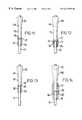
- FIG. 11shows one example of the present invention in more detail and which is for use as shown in FIGS. 7, 8 , 9 and 10 .
- the cement deflector 55is made from polymethylmethacrylate (PMMA) and is provided with a central bore 56 which is dimensioned to be a sliding fit on the guide wire 31 .
- the proximal end 57 of the deflectoris recessed at the 58 to provide a push fit onto the distal end 59 of the phantom prosthesis 50 .
- the primary advantage of the inventionis that when the phantom prosthesis or prosthesis is moved down the guide wire 31 the cement deflector 55 acts to prevent cement passing into the guide bore 60 of the prosthesis around the guide wire 31 . If the technique described with regard to FIGS. 2 to 10 is employed and a phantom prosthesis is used, if cement passes up the guide wire 31 into the bore 60 of the prosthesis and the phantom prosthesis is left in the opening until the cement part solidifies it can be difficult to withdraw the phantom prosthesis up the guide wire due to the ingress of cement. The cement deflector of the present invention prevents this happening.
- FIG. 12shows an alternative embodiment in which the same reference numerals are used to define similar parts but in this embodiment the deflector 70 is provided with an extended recess 71 the proximal end 72 of which is shaped and adapted to engage the distal end 73 of the phantom 50 .
- This constructionis designed so that when a non-cannulated prosthesis 40 , similar to that shown in FIG. 1, is employed its distal end can extend into the proximal end 72 of the recess of the deflector 70 and a void 74 is provided by the lower part of the recess 71 into which the prosthesis 40 can subsequently sink.
- this constructionas shown in FIG. 12 can be used to replace the construction shown in FIG. 11 when used in the surgery described with regards to FIGS. 9 and 10 and overcomes the requirement for a centralizer 70 .
- FIG. 13shows another alternative embodiment in which the same reference numerals are used to indicate similar parts to those shown in FIG. 11 .
- the cement deflector 80has an external diameter which is substantially the same as the external diameter of the distal end 59 of the phantom prosthesis 50 .
- the distal end of the phantom prosthesisis recessed as indicated by reference numeral 81 and receives a flange 82 formed on the end of the deflector.
- the deflectoris held in place by the flange 82 during insertion and acts in a similar manner to the inserter described and shown in FIG. 11 .
- FIG. 14shows an embodiment of cement deflector which can be used with a cannulated prosthesis.
- the same reference numeralsare again used to describe similar parts to those shown in the previous Figures.
- the cannulated prosthesisis indicated by reference numeral 90 .
- the prosthesishas a distal end 91 and a bore 92 to receive the guide wire 31 .
- a cement deflector 93is employed which has a bore 94 to receive the guide wire 31 and an enlarged bore 95 which is dimensioned to receive the distal end of the prosthesis 90 .
- the cement deflectoroperates in a similar way to that described with regard to the other examples when they are employed on a cannulated phantom.
- This embodimentcan be used either on the insertion into a newly prepared cavity in a bone or when used for replacement surgery.
- the proximal portion of the enlarged bore 95provides a void 96 in which the prosthesis 90 can subsequently sink.
Landscapes
- Health & Medical Sciences (AREA)
- Orthopedic Medicine & Surgery (AREA)
- Transplantation (AREA)
- Life Sciences & Earth Sciences (AREA)
- Animal Behavior & Ethology (AREA)
- Veterinary Medicine (AREA)
- Public Health (AREA)
- Engineering & Computer Science (AREA)
- Biomedical Technology (AREA)
- Heart & Thoracic Surgery (AREA)
- General Health & Medical Sciences (AREA)
- Oral & Maxillofacial Surgery (AREA)
- Vascular Medicine (AREA)
- Cardiology (AREA)
- Physical Education & Sports Medicine (AREA)
- Surgery (AREA)
- Nuclear Medicine, Radiotherapy & Molecular Imaging (AREA)
- Medical Informatics (AREA)
- Molecular Biology (AREA)
- Prostheses (AREA)
- Surgical Instruments (AREA)
Abstract
Description
Claims (17)
Applications Claiming Priority (2)
| Application Number | Priority Date | Filing Date | Title |
|---|---|---|---|
| GBGB9823308.3AGB9823308D0 (en) | 1998-10-23 | 1998-10-23 | Prosthetic implant cement deflector |
| GB9823308 | 1998-10-23 |
Publications (1)
| Publication Number | Publication Date |
|---|---|
| US6217583B1true US6217583B1 (en) | 2001-04-17 |
Family
ID=10841229
Family Applications (1)
| Application Number | Title | Priority Date | Filing Date |
|---|---|---|---|
| US09/418,460Expired - LifetimeUS6217583B1 (en) | 1998-10-23 | 1999-10-15 | Prosthetic implant cement deflector system |
Country Status (6)
| Country | Link |
|---|---|
| US (1) | US6217583B1 (en) |
| EP (1) | EP0995410A3 (en) |
| JP (1) | JP2000139973A (en) |
| AU (1) | AU5606599A (en) |
| CA (1) | CA2288509A1 (en) |
| GB (1) | GB9823308D0 (en) |
Cited By (6)
| Publication number | Priority date | Publication date | Assignee | Title |
|---|---|---|---|---|
| US6589285B2 (en)* | 2001-11-20 | 2003-07-08 | Centerpulse Orthopedics Inc. | Apparatus for, and method of, providing hip prosthesis implantation |
| US6656188B2 (en)* | 2000-11-22 | 2003-12-02 | Depuy Products, Inc. | Tamp assembly |
| US6840942B2 (en) | 2000-11-15 | 2005-01-11 | Benoist Girard Sas | Prosthetic implant cement deflector and method of implantation |
| US20060293710A1 (en)* | 2003-10-21 | 2006-12-28 | Arthrocare Corporation | Knotless suture lock and bone anchor implant method |
| CN110368057A (en)* | 2019-06-10 | 2019-10-25 | 浙江医院 | Percutaneous artificial femoral head replacement's device |
| US12208021B2 (en) | 2018-10-04 | 2025-01-28 | Depuy Ireland Unlimited Company | Prosthesis extraction system |
Citations (11)
| Publication number | Priority date | Publication date | Assignee | Title |
|---|---|---|---|---|
| US5092892A (en)* | 1989-11-06 | 1992-03-03 | Howmedica International Inc. | Intramedullary centralizer |
| US5156606A (en)* | 1988-10-11 | 1992-10-20 | Zimmer, Inc. | Method and apparatus for removing pre-placed prosthetic joints and preparing for their replacement |
| US5192283A (en) | 1990-08-10 | 1993-03-09 | Ling Robin S M | System for performing hip prosthesis revision surgery |
| US5385566A (en)* | 1992-02-20 | 1995-01-31 | Ullmark; Goesta | Device and a method for use in transplantation of bone tissue material |
| US5425768A (en)* | 1993-03-08 | 1995-06-20 | Carpenter; Charles W. | Reinforced spacer for stem-type prosthetic implants |
| US5554192A (en)* | 1994-10-05 | 1996-09-10 | Zimmer, Inc. | Intramedullary implant stem and centralizer |
| US5658351A (en)* | 1995-07-31 | 1997-08-19 | Howmedica Inc. | Intramedullary centralizer |
| US5665121A (en) | 1992-02-03 | 1997-09-09 | Howmedica International | Preformed mantle |
| US5755720A (en)* | 1997-01-03 | 1998-05-26 | Mikhail Michael W E | Method and apparatus for performing hip prosthesis surgery |
| US5788704A (en) | 1994-10-05 | 1998-08-04 | Howmedica International Inc. | Apparatus and method for implanting a prothesis |
| US5997581A (en)* | 1997-12-29 | 1999-12-07 | Johnson & Johnson Professional, Inc. | Hip stem cement spacer |
Family Cites Families (1)
| Publication number | Priority date | Publication date | Assignee | Title |
|---|---|---|---|---|
| DE4313201C2 (en)* | 1993-04-22 | 1995-06-01 | Depuy Orthopaedie Gmbh | Prosthetic socket set |
- 1998
- 1998-10-23GBGBGB9823308.3Apatent/GB9823308D0/ennot_activeCeased
- 1999
- 1999-10-15USUS09/418,460patent/US6217583B1/ennot_activeExpired - Lifetime
- 1999-10-20EPEP99308270Apatent/EP0995410A3/ennot_activeWithdrawn
- 1999-10-22CACA002288509Apatent/CA2288509A1/ennot_activeAbandoned
- 1999-10-25JPJP11301902Apatent/JP2000139973A/enactivePending
- 1999-10-25AUAU56065/99Apatent/AU5606599A/ennot_activeAbandoned
Patent Citations (11)
| Publication number | Priority date | Publication date | Assignee | Title |
|---|---|---|---|---|
| US5156606A (en)* | 1988-10-11 | 1992-10-20 | Zimmer, Inc. | Method and apparatus for removing pre-placed prosthetic joints and preparing for their replacement |
| US5092892A (en)* | 1989-11-06 | 1992-03-03 | Howmedica International Inc. | Intramedullary centralizer |
| US5192283A (en) | 1990-08-10 | 1993-03-09 | Ling Robin S M | System for performing hip prosthesis revision surgery |
| US5665121A (en) | 1992-02-03 | 1997-09-09 | Howmedica International | Preformed mantle |
| US5385566A (en)* | 1992-02-20 | 1995-01-31 | Ullmark; Goesta | Device and a method for use in transplantation of bone tissue material |
| US5425768A (en)* | 1993-03-08 | 1995-06-20 | Carpenter; Charles W. | Reinforced spacer for stem-type prosthetic implants |
| US5554192A (en)* | 1994-10-05 | 1996-09-10 | Zimmer, Inc. | Intramedullary implant stem and centralizer |
| US5788704A (en) | 1994-10-05 | 1998-08-04 | Howmedica International Inc. | Apparatus and method for implanting a prothesis |
| US5658351A (en)* | 1995-07-31 | 1997-08-19 | Howmedica Inc. | Intramedullary centralizer |
| US5755720A (en)* | 1997-01-03 | 1998-05-26 | Mikhail Michael W E | Method and apparatus for performing hip prosthesis surgery |
| US5997581A (en)* | 1997-12-29 | 1999-12-07 | Johnson & Johnson Professional, Inc. | Hip stem cement spacer |
Cited By (7)
| Publication number | Priority date | Publication date | Assignee | Title |
|---|---|---|---|---|
| US6840942B2 (en) | 2000-11-15 | 2005-01-11 | Benoist Girard Sas | Prosthetic implant cement deflector and method of implantation |
| US6656188B2 (en)* | 2000-11-22 | 2003-12-02 | Depuy Products, Inc. | Tamp assembly |
| US6589285B2 (en)* | 2001-11-20 | 2003-07-08 | Centerpulse Orthopedics Inc. | Apparatus for, and method of, providing hip prosthesis implantation |
| US20060293710A1 (en)* | 2003-10-21 | 2006-12-28 | Arthrocare Corporation | Knotless suture lock and bone anchor implant method |
| US12208021B2 (en) | 2018-10-04 | 2025-01-28 | Depuy Ireland Unlimited Company | Prosthesis extraction system |
| CN110368057A (en)* | 2019-06-10 | 2019-10-25 | 浙江医院 | Percutaneous artificial femoral head replacement's device |
| CN110368057B (en)* | 2019-06-10 | 2021-03-30 | 浙江医院 | Percutaneous artificial femoral head replacement device |
Also Published As
| Publication number | Publication date |
|---|---|
| JP2000139973A (en) | 2000-05-23 |
| EP0995410A3 (en) | 2002-08-07 |
| CA2288509A1 (en) | 2000-04-23 |
| EP0995410A2 (en) | 2000-04-26 |
| AU5606599A (en) | 2000-05-04 |
| GB9823308D0 (en) | 1998-12-23 |
Similar Documents
| Publication | Publication Date | Title |
|---|---|---|
| CA2159863C (en) | Apparatus and method for implanting a prosthesis | |
| EP0555004B1 (en) | Prosthesis for attachment without bone cement | |
| AU772169C (en) | Methods and instruments for radial bone impacting | |
| US4919673A (en) | Prosthesis for a femoral head | |
| DE69838237T2 (en) | Modular prosthesis system with hybrid attachment | |
| US4994085A (en) | Artificial stem unit for coxa with setting guide | |
| EP0913136B1 (en) | Tamp with horizontal steps used for impaction bone grafting in revision femur | |
| US6143030A (en) | Impaction allograft form and method of orthopaedic surgery using same | |
| US4404692A (en) | Centering system for hip replacement | |
| CA2337621A1 (en) | Contourable polymer filled implant | |
| US5222985A (en) | Implantation of articulating joint prosthesis | |
| US4851004A (en) | Implantation of articulating joint prosthesis | |
| JPH05500177A (en) | bone graft | |
| CZ131493A3 (en) | Prosthetic element for repair or replacement of femur | |
| US6217583B1 (en) | Prosthetic implant cement deflector system | |
| EP1208820B1 (en) | Prosthetic implant cement deflector and a set of components to carry out a prosthetic implant employing such a deflector | |
| US4919665A (en) | Implantation of articulating joint prosthesis | |
| US4636214A (en) | Implantation of articulating joint prosthesis | |
| GB2118441A (en) | Articulating joint prostheses | |
| EP0783275B1 (en) | Instrumentation for proximal femoral compaction broaching | |
| DE4425235A1 (en) | Self=centering hip joint prosthesis acetabulum | |
| CA2200201C (en) | Instrumentation for proximal femoral compaction broaching |
Legal Events
| Date | Code | Title | Description |
|---|---|---|---|
| AS | Assignment | Owner name:BENOIST GIRARD, SAS, A CORPORATION OF FRANCE, FRAN Free format text:ASSIGNMENT OF ASSIGNORS INTEREST;ASSIGNOR:STORER, JOHN ANDREW;REEL/FRAME:010480/0390 Effective date:19991224 | |
| STCF | Information on status: patent grant | Free format text:PATENTED CASE | |
| CC | Certificate of correction | ||
| FPAY | Fee payment | Year of fee payment:4 | |
| FPAY | Fee payment | Year of fee payment:8 | |
| FPAY | Fee payment | Year of fee payment:12 | |
| AS | Assignment | Owner name:STRYKER IRELAND LIMITED, IRELAND Free format text:CONFIRMATORY LICENSE;ASSIGNOR:BENOIST GIRARD SAS;REEL/FRAME:029674/0420 Effective date:20121126 Owner name:STRYKER IRELAND LIMITED, IRELAND Free format text:CONFIRMATORY ASSIGNMENT;ASSIGNOR:BENOIST GIRARD SAS;REEL/FRAME:029674/0420 Effective date:20121126 | |
| AS | Assignment | Owner name:STRYKER MEDTECH LIMITED, MALTA Free format text:NUNC PRO TUNC ASSIGNMENT;ASSIGNOR:STRYKER IRELAND LIMITED;REEL/FRAME:037152/0946 Effective date:20151013 Owner name:STRYKER EUROPEAN HOLDINGS I, LLC, MICHIGAN Free format text:NUNC PRO TUNC ASSIGNMENT;ASSIGNOR:STRYKER MEDTECH LIMITED;REEL/FRAME:037153/0241 Effective date:20151013 | |
| AS | Assignment | Owner name:STRYKER EUROPEAN HOLDINGS I, LLC, MICHIGAN Free format text:CORRECTIVE ASSIGNMENT TO CORRECT THE INCORRECT LISTED SERIAL NOS. 09/905,670 AND 07/092,079 PREVIOUSLY RECORDED AT REEL: 037153 FRAME: 0241. ASSIGNOR(S) HEREBY CONFIRMS THE NUNC PRO TUNC ASSIGNMENT EFFECTIVE DATE 9/29/2014;ASSIGNOR:STRYKER MEDTECH LIMITED;REEL/FRAME:038043/0011 Effective date:20151013 | |
| AS | Assignment | Owner name:STRYKER EUROPEAN OPERATIONS HOLDINGS LLC, MICHIGAN Free format text:CHANGE OF NAME;ASSIGNOR:STRYKER EUROPEAN HOLDINGS III, LLC;REEL/FRAME:052860/0716 Effective date:20190226 Owner name:STRYKER EUROPEAN HOLDINGS III, LLC, DELAWARE Free format text:NUNC PRO TUNC ASSIGNMENT;ASSIGNOR:STRYKER EUROPEAN HOLDINGS I, LLC;REEL/FRAME:052861/0001 Effective date:20200519 |