US6217510B1 - Endoscopes and endoscope devices which image regular observation images and fluorescent images as well as which provide easier operation of treatment tools - Google Patents
Endoscopes and endoscope devices which image regular observation images and fluorescent images as well as which provide easier operation of treatment toolsDownload PDFInfo
- Publication number
- US6217510B1 US6217510B1US09/165,787US16578798AUS6217510B1US 6217510 B1US6217510 B1US 6217510B1US 16578798 AUS16578798 AUS 16578798AUS 6217510 B1US6217510 B1US 6217510B1
- Authority
- US
- United States
- Prior art keywords
- images
- image
- fluorescent
- imaging means
- insertion part
- Prior art date
- Legal status (The legal status is an assumption and is not a legal conclusion. Google has not performed a legal analysis and makes no representation as to the accuracy of the status listed.)
- Expired - Lifetime
Links
Images


Classifications
- A—HUMAN NECESSITIES
- A61—MEDICAL OR VETERINARY SCIENCE; HYGIENE
- A61B—DIAGNOSIS; SURGERY; IDENTIFICATION
- A61B1/00—Instruments for performing medical examinations of the interior of cavities or tubes of the body by visual or photographical inspection, e.g. endoscopes; Illuminating arrangements therefor
- A61B1/012—Instruments for performing medical examinations of the interior of cavities or tubes of the body by visual or photographical inspection, e.g. endoscopes; Illuminating arrangements therefor characterised by internal passages or accessories therefor
- A61B1/018—Instruments for performing medical examinations of the interior of cavities or tubes of the body by visual or photographical inspection, e.g. endoscopes; Illuminating arrangements therefor characterised by internal passages or accessories therefor for receiving instruments
- A—HUMAN NECESSITIES
- A61—MEDICAL OR VETERINARY SCIENCE; HYGIENE
- A61B—DIAGNOSIS; SURGERY; IDENTIFICATION
- A61B1/00—Instruments for performing medical examinations of the interior of cavities or tubes of the body by visual or photographical inspection, e.g. endoscopes; Illuminating arrangements therefor
- A61B1/00002—Operational features of endoscopes
- A61B1/00043—Operational features of endoscopes provided with output arrangements
- A61B1/00045—Display arrangement
- A61B1/0005—Display arrangement combining images e.g. side-by-side, superimposed or tiled
- A—HUMAN NECESSITIES
- A61—MEDICAL OR VETERINARY SCIENCE; HYGIENE
- A61B—DIAGNOSIS; SURGERY; IDENTIFICATION
- A61B1/00—Instruments for performing medical examinations of the interior of cavities or tubes of the body by visual or photographical inspection, e.g. endoscopes; Illuminating arrangements therefor
- A61B1/00064—Constructional details of the endoscope body
- A61B1/00071—Insertion part of the endoscope body
- A61B1/0008—Insertion part of the endoscope body characterised by distal tip features
- A61B1/00091—Nozzles
- A—HUMAN NECESSITIES
- A61—MEDICAL OR VETERINARY SCIENCE; HYGIENE
- A61B—DIAGNOSIS; SURGERY; IDENTIFICATION
- A61B1/00—Instruments for performing medical examinations of the interior of cavities or tubes of the body by visual or photographical inspection, e.g. endoscopes; Illuminating arrangements therefor
- A61B1/04—Instruments for performing medical examinations of the interior of cavities or tubes of the body by visual or photographical inspection, e.g. endoscopes; Illuminating arrangements therefor combined with photographic or television appliances
- A61B1/043—Instruments for performing medical examinations of the interior of cavities or tubes of the body by visual or photographical inspection, e.g. endoscopes; Illuminating arrangements therefor combined with photographic or television appliances for fluorescence imaging
- A—HUMAN NECESSITIES
- A61—MEDICAL OR VETERINARY SCIENCE; HYGIENE
- A61B—DIAGNOSIS; SURGERY; IDENTIFICATION
- A61B1/00—Instruments for performing medical examinations of the interior of cavities or tubes of the body by visual or photographical inspection, e.g. endoscopes; Illuminating arrangements therefor
- A61B1/04—Instruments for performing medical examinations of the interior of cavities or tubes of the body by visual or photographical inspection, e.g. endoscopes; Illuminating arrangements therefor combined with photographic or television appliances
- A61B1/05—Instruments for performing medical examinations of the interior of cavities or tubes of the body by visual or photographical inspection, e.g. endoscopes; Illuminating arrangements therefor combined with photographic or television appliances characterised by the image sensor, e.g. camera, being in the distal end portion
- A—HUMAN NECESSITIES
- A61—MEDICAL OR VETERINARY SCIENCE; HYGIENE
- A61B—DIAGNOSIS; SURGERY; IDENTIFICATION
- A61B5/00—Measuring for diagnostic purposes; Identification of persons
- A61B5/0059—Measuring for diagnostic purposes; Identification of persons using light, e.g. diagnosis by transillumination, diascopy, fluorescence
- A61B5/0071—Measuring for diagnostic purposes; Identification of persons using light, e.g. diagnosis by transillumination, diascopy, fluorescence by measuring fluorescence emission
- A—HUMAN NECESSITIES
- A61—MEDICAL OR VETERINARY SCIENCE; HYGIENE
- A61B—DIAGNOSIS; SURGERY; IDENTIFICATION
- A61B5/00—Measuring for diagnostic purposes; Identification of persons
- A61B5/0059—Measuring for diagnostic purposes; Identification of persons using light, e.g. diagnosis by transillumination, diascopy, fluorescence
- A61B5/0082—Measuring for diagnostic purposes; Identification of persons using light, e.g. diagnosis by transillumination, diascopy, fluorescence adapted for particular medical purposes
- A61B5/0084—Measuring for diagnostic purposes; Identification of persons using light, e.g. diagnosis by transillumination, diascopy, fluorescence adapted for particular medical purposes for introduction into the body, e.g. by catheters
- A—HUMAN NECESSITIES
- A61—MEDICAL OR VETERINARY SCIENCE; HYGIENE
- A61B—DIAGNOSIS; SURGERY; IDENTIFICATION
- A61B1/00—Instruments for performing medical examinations of the interior of cavities or tubes of the body by visual or photographical inspection, e.g. endoscopes; Illuminating arrangements therefor
- A61B1/06—Instruments for performing medical examinations of the interior of cavities or tubes of the body by visual or photographical inspection, e.g. endoscopes; Illuminating arrangements therefor with illuminating arrangements
- A61B1/0638—Instruments for performing medical examinations of the interior of cavities or tubes of the body by visual or photographical inspection, e.g. endoscopes; Illuminating arrangements therefor with illuminating arrangements providing two or more wavelengths
- A—HUMAN NECESSITIES
- A61—MEDICAL OR VETERINARY SCIENCE; HYGIENE
- A61B—DIAGNOSIS; SURGERY; IDENTIFICATION
- A61B1/00—Instruments for performing medical examinations of the interior of cavities or tubes of the body by visual or photographical inspection, e.g. endoscopes; Illuminating arrangements therefor
- A61B1/06—Instruments for performing medical examinations of the interior of cavities or tubes of the body by visual or photographical inspection, e.g. endoscopes; Illuminating arrangements therefor with illuminating arrangements
- A61B1/0646—Instruments for performing medical examinations of the interior of cavities or tubes of the body by visual or photographical inspection, e.g. endoscopes; Illuminating arrangements therefor with illuminating arrangements with illumination filters
Definitions
- the present inventionrelates to endoscopes and more specifically to endoscopes and endoscope devices which are characterized by the orientation of plural images to their forceps opening when observing an object with plural images.
- Fluorescent observation endoscope devicespossess a fluorescent observation endoscope having CCDs which are provided with an imaging element to image under a white illumination and image intensifiers, such as super high-sensitive imaging elements to image subtle autofluorescence which emits from an observation object under an illumination of a light with a band from ultra-violet to blue.
- fluorescent observation endoscopesregular observation under a white light and autofluorescent observation can be conducted selectively or consecutively, and much more information on the observation object can be offered to examiners compared to the conventional endoscope devices.
- a forceps channelin introducing treatment tools such as a forceps and the like to the tip of the endoscope so that biopsy or excision of lesion parts within an observation object can be conducted under the endoscopic observation.
- illumination windows 203 a and 203 bare individually provided near the object window for regular observation use 201 and the object window for fluorescent observation use 202 , respectively.
- a forceps hole 204which is an opening part at the tip side of a forceps channel is disposed between the object window for regular observation use 201 and the illumination window 203 a ,
- a nozzle 205 for washing the object window for regular observation use 201 and the object window for fluorescent observation use 202is disposed almost in the middle, as shown in FIG.
- FIG. 11In a white observation image (FIG. 11 ), the forceps 206 appears the lower left on the monitor screen, while in a fluorescent observation image (FIG. 12 ), the forceps 206 appears from the upper left on the monitor screen.
- endoscopeswhich are used for diagnosis based on regular observation images and fluorescent observation images are formed to selectively conduct the regular observation under a white light illumination and the fluorescent observation, to observe fluorescence which is emitted from a vital tissue under an illumination of an ultraviolet-to-blue light, by means of imaging means which are installed in or connected to the endoscope.
- imaging meanswhich are installed in or connected to the endoscope.
- the first examplehas a construction where two kinds of image-formation optical systems each for the regular observation use and for fluorescent observation use are disposed in parallel. Two kinds of solid imaging elements to convert the images from these image-formation optical systems into electric signals are provided at the tip or in the operation part of the endoscope. Under illumination by a white light and an excitation light which are transferred from a light source device in a time shared way, the imaging signals which are outputted from the individual solid imaging elements are selected for conditioning and designation in accordance with the timing controls on the illumination lights.
- an object optical systemwhich is common to the regular observation and the fluorescent observation and a beam splitter which divides the regular observation image and the fluorescent observation image which are both emitted from the object optical system into two directions based on their wavelengths are provided at the tip part of an endoscope.
- Solid imaging elementswhich individually image the regular observation image and the fluorescent observation image which have been separated by the beam splitter are installed at the tip part or in the operation part of the endoscope.
- the object optical system for regular observation use and the object optical system for fluorescent observation useare provided at the tip part of the endoscope in parallel, the field of visions differ between the processes of the regular observation and the fluorescent observation. Therefore, by switching the regular observation image to the fluorescent observation image and vice versa, the field of vision of these images, which are designated on the monitor, differ each other, resulting in the problem that operators experience confusion.
- the regular observation image and the fluorescent observation imagehave a mirroring relationship, so that a special signal conditioning to reverse one of the images needs to be essential.
- the present inventionprovides an endoscope which can designate the treatment tools such as forceps or the like at almost the same position on the monitor screen for both of the processes of a white light observation and a fluorescent observation to improve the operating capabilities.
- the endoscope of the present inventionhas an illumination window which emits a regular observation light and a fluorescent observation light from the tip plane of the insertion part which is inserted into body cavities.
- An observation windowis provided where a regular observation image and a fluorescent observation image derived from said regular observation light and fluorescent observation light are injected.
- a forceps opening partwhich communicates to a forceps channel which is provided within the insertion part at the tip plane of the insertion part.
- An imaging meanswhich images said regular observation image and the fluorescent image are injected from the observation window with an orientation where the forceps opening part is positioned at the same direction in both of the images.
- the imaging meansallows an operator to designate treatment tools such as a forceps and the like at almost the same position in the monitor screen at both of the processes of the white light observation and the fluorescent observation by imaging the regular observation image and the fluorescent observation image which are injected from the observation window with an orientation where the forceps opening part is positioned at the same direction. This improves the operating capabilities.
- FIG. 1 to FIG. 6are concerning the first embodiment of the present invention
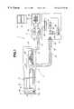
- FIG. 1is a block diagram of an endoscope device according to the present invention
- FIG. 2is a block diagram to show the construction at the tip plane of the insertion part of the endoscope of FIG. 1
- FIG. 3is a block diagram to show the construction of the first modification example at the tip plane of the insertion part of the endoscope of FIG. 1
- FIG. 4is a block diagram to show the construction of the second modification example at the tip plane of the insertion part of the endoscope of FIG. 1
- FIG. 5is an explanatory drawing to explain the operation of the endoscope of FIG. 1
- FIG. 6is the second explanatory drawing to explain the operation of the endoscope of FIG. 1, and
- FIG. 7is a diagram to show the construction of a modification example of the endoscope of FIG. 1 .
- FIG. 8 and FIG. 9concern the second embodiment of the present invention
- FIG. 8is a block diagram to show the construction of an endoscope device
- FIG. 9is a cross section to show the construction of a fluorescent camera to be used for a modification example of the endoscope device of FIG. 8 .
- FIG. 10 to FIG. 12concern a conventional example
- FIG. 10is a block diagram to show the construction at the tip plane of the insertion part of the conventional endoscope
- FIG. 11is the first explanatory drawing to explain the operation of the conventional endoscope of FIG. 10
- FIG. 12is the second explanatory drawing to explain the operation of the conventional endoscope of FIG. 10 .
- an endoscope device 1has a construction where an endoscope 2 is inserted into a body cavity and then obtains a regular observation image and a fluorescent observation image for an observation part such as an affiliated part.
- a light source device 3supplies illumination lights to the endoscope 2 .
- a signal conditioning device 4images the signals obtained by means of the endoscope 2 , and a monitor 5 designates the endoscopic images generated by the signal conditioning device 4 .
- the endoscope 2is composed of a slender insertion part 11 which is inserted into a body cavity.
- An operation part 12is provided at the proximal end of the insertion part 11 .
- a light guide cable part 13extends from the operation part 12 and is connected to the light source device 3 in a removable way.
- a signal cable part 14is connected to the signal conditioning device 4 in a removable way.
- a light guide connector 15 at the tip of the light guide cable part 13is connected to the light source device 3 in a removable way to the tip of the insertion part 11 .
- a light guide fiber 16 transfers the illumination light from the light source device 3is integral.
- An illumination window 16 ais provided at the tip part of the insertion part 11 at the side of the radiation end of this light guide fiber 16 .
- a solid imaging element 18 to conduct the regular observation under a white light illuminationis provided within the tip part of the insertion part 11 .
- a signal conductor to transfer signals to the signal conditioning device 4is provided.
- an object lens for regular observation use 20 and an object window for regular observation use 21 both in order to form images of observation parts at the solid imaging element 18are provided.
- an image guide fiber for fluorescent observation use 22is provided to be juxtaposed with the light guide fiber 16 .
- an object lens for fluorescent observation use 23 and an object window for fluorescent use 24are provided.
- a lens 25 and a high-sensitivity imaging element 26in order to, image fluorescent images at the observation parts which are transferred by the image guide fiber 22 are provided. From the high-sensitivity imaging element 26 , a signal conductor 27 to transfer signals to the signal conditioning device 4 is provided.
- Signal conductors 19 and 27are inserted in the signal cable part 14 , and are then connected to the signal conditioning device 4 through this signal cable part 14 .
- a duct linein order to insert a forceps and the like, is provided within the insertion part 11 (although it is not shown in FIG. 1) in the same way as regular endoscopes, and both of its proximal side and tip side have their individual openings at the operation part 12 and the tip plane of the insertion part 11 , respectively.
- a water supply duct linein order to supply washing water to wash the object window for regular observation window use 21 and the object window for fluorescent observation use 24 , is provided within the L 4 insertion part 11 (although it is also not shown in FIG. 1) in the same way as regular endoscopes.
- a high intensity lamp 31 of xenon, metal halide, or the likeis provided so that a light can be injected into the light guide fiber 16 through a condensing lens 32 .
- a band pass filter(which is not shown in the figure) which transmits only lights of blue band is provided between the high intensity lamp 31 and the light guide fiber 16 in a removable way by means of a rotary disc 33 .
- This rotary discis operated by a motor 35 which is controlled by a controller 34 . Therefore, in accordance with the control of the controller 34 , when the band pass filter is inserted on the light path, only lights of blue band are inserted into the light guide fiber 16 . When the band pass filter is withdrawn from the light path, a white light is injected into the light guide fiber 16 .
- the signal conditioning device 4integrates a CCU for regular observation use 41 to image the signals from solid light imaging element 18 and a CCU for fluorescent observation use 42 to imaging signals from high-sensitive imaging element 26 . Also an image switching part 43 to selectively output the imaging signals from the CCU for regular observation use 41 and the CCU for fluorescent observation use 42 is integrated therein.
- the signals which are outputted from the image switching part 43are transferred into the monitor 5 , so that the images of the tip of the endoscope are designated on a screen 51 of the monitor 5 .
- the object window for regular observation use 21is disposed at almost the middle, and next to which, the object window for fluorescent observation use 24 is provided at the upper part of the figure.
- illumination windows 16 a and 16 bare provided at both sides of the object window for regular observation use 21 and the object window for fluorescent observation use 24 . This is because light guide fiber 16 is divided into two at the tip of the insertion part 11 for preventing uneven illumination, and then at both tips the illumination windows 16 a and 16 b are provided, respectively.
- a forceps hole 61which is an opening part at the tip side of the forceps channel which is inserted into the insertion part 11 is provided at the lower right of the object window for regular observation use, so that a treatment tool which is inserted through the forceps insertion channel is extruded from the forceps hole 61 .
- a nozzle 62which is an end part at the tip side of the water supply duct line is disposed at the lower left of the object window for regular observation use 21 , and at the nozzle 62 , two opening parts 63 a and 63 b are provided which form openings at the two positions so that washing water can be sprayed towards the object window for regular observation use 21 and the object window for fluorescent observation use 24 .
- Forceps hole 61may be not always disposed in the arrangement shown in FIG. 2, and at least, for example, as shown in FIG. 3, when lines which go through the centers of the object window for regular observation use 21 and the object window for fluorescent observation use 24 and which directions are the same as the up-and-down direction of images which are designated represent L 1 and L 2 , respectively, and in the same way, when the normals of L 1 and L 2 which go through the centers of the object window for regular observation use 21 and the object window for fluorescent observation use 24 represent L 3 and L 4 , respectively, the center of the forceps hole 61 may be disposed to be within a region 64 which is shown with slanting lines.
- a constructionmay be formed where an opening part 63 c is provided as a single opening for the nozzle in terms of the nozzle 62 .
- the nozzle 62is provided in a rotatable way, so that washing water can be sprayed towards the object window for regular observation use 21 and the object window for fluorescent observation use 24 .
- the insertion part 11 of the endoscope 2is inserted into the body of a patient while observing under a white light illumination.
- the band pass filter on the rotary disc 33is in its condition of withdrawal from the optical path by means of the controller 34 , and the white light which is emitted from the high intensity lamp 31 is injected into the light guide fiber 16 to illuminate the observation area at the tip of the insertion part 11 .
- the CCU for regular observation use 41 existing within the signal conditioning device 4turns into the operating condition by means of the control signals from the controller 34 existing within the light source device 3 . Then the image of the observation area at the tip of the insertion part 11 is formed as an image and then imaged at the solid imaging element 18 by the observation window for regular observation use 21 and the object lens for regular observation use 20 .
- the signal of the solid imaging element 18is converted into an imaging signal by the CCU for regular observation use 41 , transferred to the monitor 5 through the image switching part 43 . Then the regular observation image is projected at the screen 51 .
- the band pass filter on the rotary disc 33is inserted into the optical path by means of the signal from the controller 34 existing within the light source device 3 . Then only blue lights which transmit the band pass filter are injected into the light guide fiber 16 to illuminate the area of interest.
- the fluorescence which is excited from the area of interest due to the blue lightsis introduced from the object window for fluorescent observation use 24 through the image guide fiber 22 to the high-sensitivity imaging element 26 existing within the operation part of the endoscope and then imaged.
- the signal which is obtained at the high-sensitivity imaging element 26is converted into the imaging signal at the CCU for fluorescent observation use 42 existing within the signal conditioning device 4 , and then the fluorescent image is designated on the screen 51 of the monitor 5 .
- Solid imaging element 18 and high-sensitivity imaging element 26 existing within the insertion part 11are disposed and arranged in an orientation where the UP direction shown in FIG. 2 is designated at the upper direction of the screen 51 of the monitor 5 . Therefore, when the white light regular observation is switched to the fluorescent observation, and also when the fluorescent observation is switched to the white light regular observation, images with almost the same field of vision are designated on the screen 51 of the monitor 5 .
- the regular observation imagewhen comparing the regular observation image and the fluorescent observation image, in terms of the regular observation image, because a relatively bright image can be obtained, the operations such as a treatment and the like becomes easier.
- the fluorescent observation imageit is characterized in that because an image which includes the functional information on the tissue which can not be seen with the regular observation image, a specific area can be easily detected. Therefore, in order to carry out accurate biopsy or ablation, it is effective to conduct the operation while switching between the white light regular observation and the fluorescent observation.
- the treatment toolis designated at almost the same position of the endoscopic image on the monitor screen, even if the treatment is conducted with switching both of the observation images, the operator will not be troubled with any confusions as well as be able to accurately manipulate the treatment tool.
- the lens 25 and the high-sensitivity imaging element 26are disposed at the proximal end of the image guide fiber 22 so that the fluorescent image at the observation area which is transferred by the image guide fiber 22 is imaged by the high-sensitivity imaging element 26 , as shown in FIG. 7, the lens 25 and the high-sensitivity imaging element 26 may be provided within the tip part of the insertion part 11 so that the fluorescent observation image which is injected from the object window for fluorescent observation use 24 is imaged by the high-sensitivity imaging element 26 .
- an endoscope device 101is composed of an endoscope main body 110 , a light source device 130 which provides an illumination light to the endoscope main body 110 , a signal conditioning device 140 which images an imaging signal which is obtained from the endoscope main body 110 , and a monitor device 150 which designates the endoscopic image.
- the endoscope main body 110is composed of an operation part 111 to conduct insertion operations and treatment operations, and also to direct part of signal conditioning, a slender insertion part 112 which is inserted into a body cavity, the light guide cable part 113 which introduces an illumination light from the light source device 130 to the endoscope main body 110 , and a signal cable part 114 which transfers the imaging signal from the endoscope main body 110 to the signal conditioning device 140 .
- the light guide connector 115In order to connect both of which is provided.
- the light guide fiber 116is integrated from the light guide connector 115 to the tip of the insertion part 112 through the insides of the light guide cable part 113 , the operation part 111 and the insertion part 112 .
- an illumination window 117is disposed opposite to the tip side of the light guide fiber 116 .
- an observation window 118is disposed and at the back side thereof, an image-formation optical system 119 to form the endoscopic image is provided.
- a prism 120which converts the optical path by 90° degrees is provided.
- the prism 120is fixed at the linear actuator 122 through a support 121 .
- the linear actuator 122can shift the prism 122 along the optical axis of the image-formation optical system 119 to steadily position the prism 120 at either of the two positions shown with the solid line and the broken line in the figure.
- a peizo-actuatorwhich is driven by a peizo-electric element (the one which possesses an inch-worm mechanism or the one which is driven by an ultrasonic motor mechanism are best suitable), or an electrostatic actuator which utilizes electrostatic force is suitable.
- an electric wire 123to control the driving thereof is provided and extended to a signal conditioning device 140 .
- a solid imaging element 124 to conduct the regular observationis disposed on the image-formation plane of the image-formation optical system 119 which exists at the optical path which is converted by the prism 120 which is positioned at the position shown with the broken line in the figure.
- the normal of the receiving plane 124 a of the solid imaging element 124is disposed to cross at right angle with the longitudinal direction of the insertion part 112 .
- a high-sensitivity imaging element 125 to conduct the fluorescent observationis disposed on the image-formation plane of the image-formation optical system 119 which exists at the optical path which is converted by the prism 120 which is positioned at the position shown with the solid line in the figure. Since fluorescent observation images have lower intensities compared with those of regular observation images, it is suitable to use an imaging element which possesses amplification functions, for example a CMD (Charge Modulation Device) or the like as the high-sensitivity imaging element 125 .
- CMDCharge Modulation Device
- the normal of the receiving plane 125 a of the solid imaging element 125is disposed to cross at right angles with the longitudinal direction of the insertion part 112 .
- a high intensity lamp 131such as a Xenon lamp, a metal halide lamp or the like is provided.
- the light which is generated by the high intensity lamp 131is injected into the end plane of the light guide fiber 116 through a condensing lens 132 .
- a band pass filter which transmits only lights with a blue bandis provided in a removable manner by means of a rotary disc 133 .
- This rotary disc 133is driven by the motor 135 which is controlled by a controller 134 .
- the driving control of the motor 135 by the controller 134is conducted based on the direction signals which are inputted from the regular/fluorescence observation changing switch 136 into the controller 134 .
- the regular/fluorescence observation changing switch 136is provided in the light source device 130 , it may be provided in the operation part 111 of the endoscope main body 110 , or may be formed as an independent foot switch. These cases are highly suitable for operations in terms of the operations, because the operator can conduct the switching operation while conducting the observation operation of the endoscope main body 110 .
- the above-mentioned band pass filterwhen the above-mentioned band pass filter is inserted into the optical path, only lights with a blue band are injected into the light guide fiber 116 , and when the band pass filter is withdrawn from the optical path, a white light is injected therein.
- the signal conditioning part for regular observation use 141which images the imaging signal from the solid imaging element 124 and the signal conditioning part for fluorescent observation use 142 which images the imaging signal from the high-sensitivity imaging element 125 are integrated, and both of which are connected to the solid imaging element 124 and the high-sensitivity imaging element 125 through electric wires, respectively.
- the picture signals which the signal conditioning part for regular observation use 141 and the signal conditioning part for fluorescent observation use 142 outputare inputted into the image switching part 143 .
- the selection signal which selects either the regular observation or the fluorescent observation, which the controller 134 generates based on the direction signal from the regular/fluorescent observation changing switch 136is inputted, and the picture signals of the signal conditioning part for regular observation use 141 and the signal conditioning part for fluorescent observation use 142 are selected to output therein.
- the signal conditioning part for regular observation use 141 and the signal conditioning part for fluorescent observation use 142have individual driving circuits (which are not shown in the figure) which supply the driving signals to the solid imaging element 124 and the high-sensitivity imaging element 125 , respectively.
- the drive control part 144 which drives the linear actuator 122is integrated and it generates prism driving signals to position the prism 120 onto the position which is shown with the above-mentioned broken line or the solid line.
- the above-mentioned selection signalis also connected to the signal conditioning part for regular observation use 141 and the signal conditioning part for fluorescent observation use 142 , and is subject to the ON/OFF control of the signal output operation of the driving circuit of the corresponding signal conditioning part and the imaging element in accordance with the type of the observation image which the selection signal represent (in other words, the regular observation image and the fluorescent observation image).
- the imaging signal which is outputted from the image switching part 143is transferred to the monitor device 150 and then designated onto the screen 151 .
- a certain signalis transferred from the controller 134 to each part to turn the endoscope device 101 into the regular observation mode. Then, the insertion part 112 is inserted into a body, while observing it under the white light illumination.
- the above-mentioned band pass filter of the light source device 130is in the condition of its withdrawal from the optical path, so that the white light which is radiated from the high intensity lamp 131 is injected into the light guide fiber 116 and then illuminates the object from the illumination window 117 which is provided at the tip of the insertion part 112 .
- the prism 120Under the condition where the white light is radiated from the light source device 130 , by the selection signal from the controller 134 within the light source device 130 , the prism 120 is positioned at the position which is shown with the broken line of the figure. Therefore, the endoscopic image from an object forms an image on the solid imaging element 124 through the observation window 118 , the image-formation optical system 119 and the prism 120 .
- the signal conditioning part for regular observation use 141 and the solid imaging element 124 which is integrated thereinis set in its operation condition.
- the endoscopic image which is formed on the solid imaging element 124is converted into the imaging signal and then inputted into the signal conditioning part for regular observation use 141 .
- conversional conditioning into-the imaging signalis transferred into the monitor device 150 through the image switching part 143 and the regular observation image is projected onto the screen 151 .
- the operatorturns the endoscope device into the fluorescent observation mode by means of the regular/fluorescent observation changing switch 136 .
- the band pass filteris inserted into the optical path between the high intensity lamp 131 and the light guide fiber 116 by the signal from the controller 134 , and only the blue light which transmits the band pass filter is injected into the light guide fiber 116 to illuminate the object.
- the prism 120In the fluorescent observation mode, by the selection signal from the controller 134 within the light source device 130 , the prism 120 is positioned at the position which is shown with the solid line in the figure. Therefore, the endoscopic image from the object is formed on the high-intensity imaging element 125 through the observation window 118 , the image-formation optical system 119 and the prism 120 .
- the driving circuit of the signal conditioning part for fluorescent observation use 142 and the high-sensitivity imaging element 125 which is integrated thereinis set in its operation condition.
- the endoscopic image which is formed at the high-sensitivity imaging element 125is converted into the imaging signal and then inputted into the conditioning part for fluorescent observation use 142 , and after the conversional conditioning into the picture signal, is transferred into the monitor device 150 through the image switching part 143 , and then the fluorescent observation image is projected onto the screen 151 .
- an endoscopic imageis formed onto the solid imaging element 124 and the high-sensitivity imaging element 125 through the same observation window 118 and the image-formation optical system 119 , so that the same field of view can be obtained with both of the observation modes.
- the comparative examinationcan be easily conducted.
- the endoscope device 101since the images with entirely the same field of view are designated in the processes of the regular observation and the fluorescent observation, operators will not experience confusion. Moreover, since the high-sensitivity imaging element is disposed at the tip of the insertion part of the endoscope, which is the closest position to an observation subject, bright and clear fluorescent images can be obtained.
- This modification exampleis an application part in the second embodiment of the optical system which is loaded at the tip of the insertion part of the endoscope onto the fluorescent observation camera which is to be installed onto the eyepiece.
- the fluorescent observation camera 160As shown in FIG. 9, the fluorescent observation camera 160 according to the modification example of this embodiment is used with it mounted onto the eyepiece part 162 which is directly connected to the operation part 161 of the fiber scope. Further, the optical system within the eyepiece part 162 is movable towards the direction of the optical axis, so that it shifts when the fluorescent observation camera 160 is mounted to form the real image of the endoscopic image which is transferred to the end plane of the image guide fiber of the fiber scope onto a certain image-formation plane.
- the solid imaging element 163 which is used for the regular observation and the high-sensitivity imaging element 164 which is used for the fluorescent observationare provided to be juxtaposed.
- the high-sensitivity imaging elementother than CMD mentioned above, a CCD where an intensifier which multiplies quantity of light is provided at its front can be used as highly suitable one.
- the prism 165which rotates the optical path 90-degrees is provided.
- the position adjusting lever 166is directly connected, and at the end part of the position adjusting lever 166 , the knob 167 is provided and is extended out to the housing 168 of the fluorescent observation camera 160 .
- the prism 165shifts to the position of the broken line of the figure and forms the endoscopic image onto the solid imaging element 163 which is provided onto the image-formation plane of the eyepiece part 162 .
- the prism 165shifts to the position of the solid line of the figure and forms the endoscopic image onto the high-sensitivity imaging element 164 which is provided onto the image-formation plane of the eyepiece part 162 .
- the electric wires which receive the operation signal and the imaging signal between the solid imaging element 163 and the high-sensitivity imaging element 164 and the individual signal conditioning parts, respectively,are in a bundle.
- the light source device 130Since the light source device 130 , the signal conditioning device 140 and the monitor device 150 are the same as those shown in FIG. 7, these illustrations will be omitted.
- the fluorescent observation camera 160is mounted onto the eyepiece part 162 of the fiber scope.
- the regular observation modeis set using the regular/fluorescent observation changing switch 136 of the light source device 130 .
- the fluorescent observation modeis set using the regular/fluorescent observation changing switch 136 of the light source device 130 .
- the other operationsare the same as those of the first embodiment.
- the fluorescent observationcan be conducted using a special optical system or a regular fiber scope which does not posses any imaging elements. Therefore, it is extremely economic, since the fluorescent observation can be conducted only with adding a camera to the existing apparatus. Moreover, since a variety of fiber scopes which have different lengths and/or outer diameters can be utilized, the fluorescent observation on a variety of areas of the body can be conducted.
Landscapes
- Health & Medical Sciences (AREA)
- Life Sciences & Earth Sciences (AREA)
- Surgery (AREA)
- Medical Informatics (AREA)
- Molecular Biology (AREA)
- Veterinary Medicine (AREA)
- Pathology (AREA)
- Public Health (AREA)
- Biophysics (AREA)
- Engineering & Computer Science (AREA)
- Biomedical Technology (AREA)
- Heart & Thoracic Surgery (AREA)
- Physics & Mathematics (AREA)
- General Health & Medical Sciences (AREA)
- Animal Behavior & Ethology (AREA)
- Nuclear Medicine, Radiotherapy & Molecular Imaging (AREA)
- Radiology & Medical Imaging (AREA)
- Optics & Photonics (AREA)
- Endoscopes (AREA)
Abstract
Description
1. Field of the Invention
The present invention relates to endoscopes and more specifically to endoscopes and endoscope devices which are characterized by the orientation of plural images to their forceps opening when observing an object with plural images.
2. Description of the Related Art
Recently, a technology is known that autofluorescence from organisms or fluorescence of drugs which are injected into organisms is detected by, for example, an endoscope or the like as two-dimensional images. Diagnostic analysis can be performed on degeneration of vital tissues and disease conditions (for example, types of the diseases and the infiltrated areas) of cancers or the like.
When a light is illuminated onto a vital tissue, a fluorescence with a longer wavelength than that of the excitation light is generated. As fluorescent substances existing in organisms, for example, NADH (nicotineamide adenine dinucleotide), FMN (Flavin mononucleotide), pyridine nucleotide and the like can be mentioned. Recently, the interrelationship between such biological, endogenous substances and diseases has been increasingly made clear. In addition, since HpD (hematoporphyrin), Photofrin, and ALA (δ-amino levulinic acid) show clustering activities towards cancers, by injecting the substance into an organism and then observing the fluorescence of the substance, the disease area can be diagnosed.
Because such a fluorescence is extremely subtle, an extremely high-sensitive projection is essential for the observation. A device to conduct this high-sensitive projection is described, for example, in Japanese Unexamined Patent Publication No. 8-252218. Fluorescent observation endoscope devices possess a fluorescent observation endoscope having CCDs which are provided with an imaging element to image under a white illumination and image intensifiers, such as super high-sensitive imaging elements to image subtle autofluorescence which emits from an observation object under an illumination of a light with a band from ultra-violet to blue.
In accordance with such fluorescent observation endoscopes, regular observation under a white light and autofluorescent observation can be conducted selectively or consecutively, and much more information on the observation object can be offered to examiners compared to the conventional endoscope devices.
In general, is provided for an endoscope, a forceps channel in introducing treatment tools such as a forceps and the like to the tip of the endoscope so that biopsy or excision of lesion parts within an observation object can be conducted under the endoscopic observation.
In terms of the conventional fluorescent observation endoscopes, however, no description has made on positional relationship among an objective window for white light regular observation use, an objective window for fluorescent observation use, both of which exist at the tip part of the endoscope, and a forceps hole.
For example, in a conventional fluorescent observation endoscope, as shown in FIG. 10, when an object window forregular observation use 201 and an object window forfluorescent observation use 202 are disposed to be in the upper and lower position, respectively, at the tip plane of the endoscope in the figure,illumination windows regular observation use 201 and the object window forfluorescent observation use 202, respectively. Further, aforceps hole 204 which is an opening part at the tip side of a forceps channel is disposed between the object window forregular observation use 201 and theillumination window 203a, Anozzle 205 for washing the object window forregular observation use 201 and the object window forfluorescent observation use 202 is disposed almost in the middle, as shown in FIG.11 and FIG.12. In a white observation image (FIG.11), theforceps 206 appears the lower left on the monitor screen, while in a fluorescent observation image (FIG.12), theforceps 206 appears from the upper left on the monitor screen.
In other words, because in some cases, in both of the regular observation images and the fluorescent observation images, treatments are conducted by theforceps 206 and the like, when the position of theforceps 206 on the monitor screen is different between the regular observation images and for the fluorescent observation images, a problem occurs that this situation throws operators into confusion.
In addition, endoscopes which are used for diagnosis based on regular observation images and fluorescent observation images are formed to selectively conduct the regular observation under a white light illumination and the fluorescent observation, to observe fluorescence which is emitted from a vital tissue under an illumination of an ultraviolet-to-blue light, by means of imaging means which are installed in or connected to the endoscope. Plural examples for these endoscopes are described in Japanese Unexamined Patent Application 8-252218.
The first example has a construction where two kinds of image-formation optical systems each for the regular observation use and for fluorescent observation use are disposed in parallel. Two kinds of solid imaging elements to convert the images from these image-formation optical systems into electric signals are provided at the tip or in the operation part of the endoscope. Under illumination by a white light and an excitation light which are transferred from a light source device in a time shared way, the imaging signals which are outputted from the individual solid imaging elements are selected for conditioning and designation in accordance with the timing controls on the illumination lights.
In the second example, an object optical system which is common to the regular observation and the fluorescent observation and a beam splitter which divides the regular observation image and the fluorescent observation image which are both emitted from the object optical system into two directions based on their wavelengths are provided at the tip part of an endoscope. Solid imaging elements which individually image the regular observation image and the fluorescent observation image which have been separated by the beam splitter are installed at the tip part or in the operation part of the endoscope.
But, because in the first endoscope device of Japanese Unexamined Patent Application 8-252218, the object optical system for regular observation use and the object optical system for fluorescent observation use are provided at the tip part of the endoscope in parallel, the field of visions differ between the processes of the regular observation and the fluorescent observation. Therefore, by switching the regular observation image to the fluorescent observation image and vice versa, the field of vision of these images, which are designated on the monitor, differ each other, resulting in the problem that operators experience confusion.
Also, with the second endoscope device of Japanese Unexamined Patent Application 8-252218, due to the reflex action of the beam splitter, the regular observation image and the fluorescent observation image have a mirroring relationship, so that a special signal conditioning to reverse one of the images needs to be essential.
The present invention provides an endoscope which can designate the treatment tools such as forceps or the like at almost the same position on the monitor screen for both of the processes of a white light observation and a fluorescent observation to improve the operating capabilities.
The endoscope of the present invention has an illumination window which emits a regular observation light and a fluorescent observation light from the tip plane of the insertion part which is inserted into body cavities. An observation window is provided where a regular observation image and a fluorescent observation image derived from said regular observation light and fluorescent observation light are injected. A forceps opening part which communicates to a forceps channel which is provided within the insertion part at the tip plane of the insertion part. An imaging means which images said regular observation image and the fluorescent image are injected from the observation window with an orientation where the forceps opening part is positioned at the same direction in both of the images. The imaging means allows an operator to designate treatment tools such as a forceps and the like at almost the same position in the monitor screen at both of the processes of the white light observation and the fluorescent observation by imaging the regular observation image and the fluorescent observation image which are injected from the observation window with an orientation where the forceps opening part is positioned at the same direction. This improves the operating capabilities.
The other characteristics and advantages of the present invention will be sufficiently clear with the help of the following illustrations.
FIG. 1 to FIG. 6 are concerning the first embodiment of the present invention; FIG. 1 is a block diagram of an endoscope device according to the present invention; FIG. 2 is a block diagram to show the construction at the tip plane of the insertion part of the endoscope of FIG. 1; FIG. 3 is a block diagram to show the construction of the first modification example at the tip plane of the insertion part of the endoscope of FIG. 1; FIG. 4 is a block diagram to show the construction of the second modification example at the tip plane of the insertion part of the endoscope of FIG. 1; FIG. 5 is an explanatory drawing to explain the operation of the endoscope of FIG. 1; FIG. 6 is the second explanatory drawing to explain the operation of the endoscope of FIG. 1, and; FIG. 7 is a diagram to show the construction of a modification example of the endoscope of FIG.1.
FIG.8 and FIG. 9 concern the second embodiment of the present invention; FIG. 8 is a block diagram to show the construction of an endoscope device, and; FIG. 9 is a cross section to show the construction of a fluorescent camera to be used for a modification example of the endoscope device of FIG.8.
FIG. 10 to FIG. 12 concern a conventional example; FIG. 10 is a block diagram to show the construction at the tip plane of the insertion part of the conventional endoscope; FIG. 11 is the first explanatory drawing to explain the operation of the conventional endoscope of FIG. 10, and; FIG. 12 is the second explanatory drawing to explain the operation of the conventional endoscope of FIG.10.
The first embodiment:
In this embodiment, as shown in FIG. 1, an endoscope device1 has a construction where anendoscope 2 is inserted into a body cavity and then obtains a regular observation image and a fluorescent observation image for an observation part such as an affiliated part. Alight source device 3 supplies illumination lights to theendoscope 2. Asignal conditioning device 4 images the signals obtained by means of theendoscope 2, and amonitor 5 designates the endoscopic images generated by thesignal conditioning device 4.
Theendoscope 2 is composed of aslender insertion part 11 which is inserted into a body cavity. Anoperation part 12 is provided at the proximal end of theinsertion part 11. A lightguide cable part 13 extends from theoperation part 12 and is connected to thelight source device 3 in a removable way. Asignal cable part 14 is connected to thesignal conditioning device 4 in a removable way.
Further, alight guide connector 15 at the tip of the lightguide cable part 13 is connected to thelight source device 3 in a removable way to the tip of theinsertion part 11. Alight guide fiber 16 transfers the illumination light from thelight source device 3 is integral. Anillumination window 16ais provided at the tip part of theinsertion part 11 at the side of the radiation end of thislight guide fiber 16.
Also, asolid imaging element 18 to conduct the regular observation under a white light illumination is provided within the tip part of theinsertion part 11. From thesolid imaging element 18, a signal conductor to transfer signals to thesignal conditioning device 4 is provided. At the tip part of theinsertion part 11 which is in front of the imaging plane side of thesolid imaging element 18, an object lens forregular observation use 20 and an object window forregular observation use 21 both in order to form images of observation parts at thesolid imaging element 18 are provided.
In theinsertion part 11, an image guide fiber forfluorescent observation use 22 is provided to be juxtaposed with thelight guide fiber 16. At the tip part of theinsertion part 11 at the tip the of saidimage guide fiber 22, an object lens forfluorescent observation use 23 and an object window forfluorescent use 24 are provided. And at the proximal side of theimage guide fiber 22 within theoperation part 12, alens 25 and a high-sensitivity imaging element 26 in order to, image fluorescent images at the observation parts which are transferred by theimage guide fiber 22 are provided. From the high-sensitivity imaging element 26, asignal conductor 27 to transfer signals to thesignal conditioning device 4 is provided.
Furthermore, a duct line, called a forceps channel, in order to insert a forceps and the like, is provided within the insertion part11 (although it is not shown in FIG. 1) in the same way as regular endoscopes, and both of its proximal side and tip side have their individual openings at theoperation part 12 and the tip plane of theinsertion part 11, respectively. In addition, a water supply duct line, in order to supply washing water to wash the object window for regularobservation window use 21 and the object window forfluorescent observation use 24, is provided within the L4 insertion part11 (although it is also not shown in FIG. 1) in the same way as regular endoscopes.
In thelight source device 3, ahigh intensity lamp 31 of xenon, metal halide, or the like is provided so that a light can be injected into thelight guide fiber 16 through a condensinglens 32. Moreover, a band pass filter (which is not shown in the figure) which transmits only lights of blue band is provided between thehigh intensity lamp 31 and thelight guide fiber 16 in a removable way by means of arotary disc 33.
This rotary disc is operated by amotor 35 which is controlled by acontroller 34. Therefore, in accordance with the control of thecontroller 34, when the band pass filter is inserted on the light path, only lights of blue band are inserted into thelight guide fiber 16. When the band pass filter is withdrawn from the light path, a white light is injected into thelight guide fiber 16.
Thesignal conditioning device 4 integrates a CCU forregular observation use 41 to image the signals from solidlight imaging element 18 and a CCU forfluorescent observation use 42 to imaging signals from high-sensitive imaging element 26. Also animage switching part 43 to selectively output the imaging signals from the CCU forregular observation use 41 and the CCU forfluorescent observation use 42 is integrated therein.
Then the signals which are outputted from theimage switching part 43 are transferred into themonitor 5, so that the images of the tip of the endoscope are designated on ascreen 51 of themonitor 5.
As shown in FIG. 2, at the tip of theinsertion part 11, the object window forregular observation use 21 is disposed at almost the middle, and next to which, the object window forfluorescent observation use 24 is provided at the upper part of the figure.
And at both sides of the object window forregular observation use 21 and the object window forfluorescent observation use 24,illumination windows light guide fiber 16 is divided into two at the tip of theinsertion part 11 for preventing uneven illumination, and then at both tips theillumination windows
Aforceps hole 61 which is an opening part at the tip side of the forceps channel which is inserted into theinsertion part 11 is provided at the lower right of the object window for regular observation use, so that a treatment tool which is inserted through the forceps insertion channel is extruded from theforceps hole 61.
Also, anozzle 62 which is an end part at the tip side of the water supply duct line is disposed at the lower left of the object window forregular observation use 21, and at thenozzle 62, two openingparts regular observation use 21 and the object window forfluorescent observation use 24.
As shown in FIG. 4, a construction may be formed where anopening part 63cis provided as a single opening for the nozzle in terms of thenozzle 62. Thenozzle 62 is provided in a rotatable way, so that washing water can be sprayed towards the object window forregular observation use 21 and the object window forfluorescent observation use 24.
The operation of the embodiment which has such a construction will be illustrated.
First, theinsertion part 11 of theendoscope 2 is inserted into the body of a patient while observing under a white light illumination.
Under the condition of the white light observation, in thelight source device 3, the band pass filter on therotary disc 33 is in its condition of withdrawal from the optical path by means of thecontroller 34, and the white light which is emitted from thehigh intensity lamp 31 is injected into thelight guide fiber 16 to illuminate the observation area at the tip of theinsertion part 11.
Under the condition where the white light is emitted from such alight source device 3, the CCU forregular observation use 41 existing within thesignal conditioning device 4 turns into the operating condition by means of the control signals from thecontroller 34 existing within thelight source device 3. Then the image of the observation area at the tip of theinsertion part 11 is formed as an image and then imaged at thesolid imaging element 18 by the observation window forregular observation use 21 and the object lens forregular observation use 20. The signal of thesolid imaging element 18 is converted into an imaging signal by the CCU forregular observation use 41, transferred to themonitor 5 through theimage switching part 43. Then the regular observation image is projected at thescreen 51.
When it is confirmed that theinsertion part 11 reaches the area of interest for the fluorescent observation by the regular observation by means of theendoscope 2, an operator switches the condition into the fluorescent observation condition.
Under the fluorescent observation condition, the band pass filter on therotary disc 33 is inserted into the optical path by means of the signal from thecontroller 34 existing within thelight source device 3. Then only blue lights which transmit the band pass filter are injected into thelight guide fiber 16 to illuminate the area of interest. The fluorescence which is excited from the area of interest due to the blue lights is introduced from the object window forfluorescent observation use 24 through theimage guide fiber 22 to the high-sensitivity imaging element 26 existing within the operation part of the endoscope and then imaged. Then, the signal which is obtained at the high-sensitivity imaging element 26 is converted into the imaging signal at the CCU forfluorescent observation use 42 existing within thesignal conditioning device 4, and then the fluorescent image is designated on thescreen 51 of themonitor 5.
When biopsy or ablation of the observation object tissue is carried out in the process of the white light observation an d the fluorescent observation, with inserting treatment tools from the forceps insertion opening of the ope ration part 11 of theendoscope 2 and then extruding them from theforceps hole 61, the operation is carried out while watching the endoscopic image which is projected on thescreen 51 of themonitor 5.
Furthermore, when comparing the regular observation image and the fluorescent observation image, in terms of the regular observation image, because a relatively bright image can be obtained, the operations such as a treatment and the like becomes easier. On the other hand, with the fluorescent observation image, it is characterized in that because an image which includes the functional information on the tissue which can not be seen with the regular observation image, a specific area can be easily detected. Therefore, in order to carry out accurate biopsy or ablation, it is effective to conduct the operation while switching between the white light regular observation and the fluorescent observation.
In this embodiment, by displacing theforceps hole 61 in regard to the object window forregular observation use 21 and the object window forfluorescent observation use 24 as shown in FIG. 2, in any of the regular observation image (FIG. 5) and the fluorescent observation image (FIG. 6) which are designated on thescreen 51 of themonitor 5, atreatment tool 71 which is inserted from the forceps insertion opening of theoperation part 11 and then extruded from theforceps hole 61 is designated at almost the same position so that the operator can conduct the treatment without any confusions.
In other words, since at any of the processes of the white light regular observation and the fluorescent observation, the treatment tool is designated at almost the same position of the endoscopic image on the monitor screen, even if the treatment is conducted with switching both of the observation images, the operator will not be troubled with any confusions as well as be able to accurately manipulate the treatment tool.
Although in this embodiment, a construction is formed where thelens 25 and the high-sensitivity imaging element 26 are disposed at the proximal end of theimage guide fiber 22 so that the fluorescent image at the observation area which is transferred by theimage guide fiber 22 is imaged by the high-sensitivity imaging element 26, as shown in FIG. 7, thelens 25 and the high-sensitivity imaging element 26 may be provided within the tip part of theinsertion part 11 so that the fluorescent observation image which is injected from the object window forfluorescent observation use 24 is imaged by the high-sensitivity imaging element 26.
The second embodiment:
As shown in FIG. 8, anendoscope device 101 is composed of an endoscope main body110, alight source device 130 which provides an illumination light to the endoscope main body110, asignal conditioning device 140 which images an imaging signal which is obtained from the endoscope main body110, and amonitor device 150 which designates the endoscopic image.
The endoscope main body110 is composed of anoperation part 111 to conduct insertion operations and treatment operations, and also to direct part of signal conditioning, aslender insertion part 112 which is inserted into a body cavity, the lightguide cable part 113 which introduces an illumination light from thelight source device 130 to the endoscope main body110, and asignal cable part 114 which transfers the imaging signal from the endoscope main body110 to thesignal conditioning device 140.
At the side of thelight source device 130 of the lightguide cable part 113, thelight guide connector 115 in order to connect both of which is provided. Thelight guide fiber 116 is integrated from thelight guide connector 115 to the tip of theinsertion part 112 through the insides of the lightguide cable part 113, theoperation part 111 and theinsertion part 112. At the tip side of theinsertion part 112, anillumination window 117 is disposed opposite to the tip side of thelight guide fiber 116.
At the tip of theinsertion part 112, an observation window118 is disposed and at the back side thereof, an image-formationoptical system 119 to form the endoscopic image is provided.
At the optical axis on the radiation side of the image-formationoptical system 119, aprism 120 which converts the optical path by 90° degrees is provided. Theprism 120 is fixed at thelinear actuator 122 through asupport 121. Thelinear actuator 122 can shift theprism 122 along the optical axis of the image-formationoptical system 119 to steadily position theprism 120 at either of the two positions shown with the solid line and the broken line in the figure. As such alinear actuator 122, a peizo-actuator which is driven by a peizo-electric element (the one which possesses an inch-worm mechanism or the one which is driven by an ultrasonic motor mechanism are best suitable), or an electrostatic actuator which utilizes electrostatic force is suitable. From thelinear actuator 122, anelectric wire 123 to control the driving thereof is provided and extended to asignal conditioning device 140.
On the image-formation plane of the image-formationoptical system 119 which exists at the optical path which is converted by theprism 120 which is positioned at the position shown with the broken line in the figure, asolid imaging element 124 to conduct the regular observation is disposed. The normal of the receiving plane124aof thesolid imaging element 124 is disposed to cross at right angle with the longitudinal direction of theinsertion part 112.
On the image-formation plane of the image-formationoptical system 119 which exists at the optical path which is converted by theprism 120 which is positioned at the position shown with the solid line in the figure, a high-sensitivity imaging element 125 to conduct the fluorescent observation is disposed. Since fluorescent observation images have lower intensities compared with those of regular observation images, it is suitable to use an imaging element which possesses amplification functions, for example a CMD (Charge Modulation Device) or the like as the high-sensitivity imaging element 125.
The normal of the receivingplane 125aof thesolid imaging element 125 is disposed to cross at right angles with the longitudinal direction of theinsertion part 112.
In thelight source device 130, ahigh intensity lamp 131 such as a Xenon lamp, a metal halide lamp or the like is provided. The light which is generated by thehigh intensity lamp 131 is injected into the end plane of thelight guide fiber 116 through a condensinglens 132.
Between thehigh intensity lamp 131 and the end plane of thelight guide fiber 116, a band pass filter which transmits only lights with a blue band is provided in a removable manner by means of arotary disc 133. Thisrotary disc 133 is driven by themotor 135 which is controlled by acontroller 134. The driving control of themotor 135 by thecontroller 134 is conducted based on the direction signals which are inputted from the regular/fluorescenceobservation changing switch 136 into thecontroller 134. Moreover, although in FIG. 7, the regular/fluorescenceobservation changing switch 136 is provided in thelight source device 130, it may be provided in theoperation part 111 of the endoscope main body110, or may be formed as an independent foot switch. These cases are highly suitable for operations in terms of the operations, because the operator can conduct the switching operation while conducting the observation operation of the endoscope main body110.
By means of the above-mentioned construction of thelight source device 130, when the above-mentioned band pass filter is inserted into the optical path, only lights with a blue band are injected into thelight guide fiber 116, and when the band pass filter is withdrawn from the optical path, a white light is injected therein.
In thesignal conditioning device 140, the signal conditioning part forregular observation use 141 which images the imaging signal from thesolid imaging element 124 and the signal conditioning part forfluorescent observation use 142 which images the imaging signal from the high-sensitivity imaging element 125 are integrated, and both of which are connected to thesolid imaging element 124 and the high-sensitivity imaging element 125 through electric wires, respectively.
The picture signals which the signal conditioning part forregular observation use 141 and the signal conditioning part forfluorescent observation use 142 output are inputted into theimage switching part 143. In theimage switching part 143, the selection signal which selects either the regular observation or the fluorescent observation, which thecontroller 134 generates based on the direction signal from the regular/fluorescentobservation changing switch 136 is inputted, and the picture signals of the signal conditioning part forregular observation use 141 and the signal conditioning part forfluorescent observation use 142 are selected to output therein.
The signal conditioning part forregular observation use 141 and the signal conditioning part forfluorescent observation use 142 have individual driving circuits (which are not shown in the figure) which supply the driving signals to thesolid imaging element 124 and the high-sensitivity imaging element 125, respectively.
Moreover, in thesignal conditioning device 140, thedrive control part 144 which drives thelinear actuator 122 is integrated and it generates prism driving signals to position theprism 120 onto the position which is shown with the above-mentioned broken line or the solid line.
In addition, the above-mentioned selection signal is also connected to the signal conditioning part forregular observation use 141 and the signal conditioning part forfluorescent observation use 142, and is subject to the ON/OFF control of the signal output operation of the driving circuit of the corresponding signal conditioning part and the imaging element in accordance with the type of the observation image which the selection signal represent (in other words, the regular observation image and the fluorescent observation image).
The imaging signal which is outputted from theimage switching part 143 is transferred to themonitor device 150 and then designated onto thescreen 151.
The operation of this embodiment is illustrated as follows:
First, a certain signal is transferred from thecontroller 134 to each part to turn theendoscope device 101 into the regular observation mode. Then, theinsertion part 112 is inserted into a body, while observing it under the white light illumination.
With the regular observation mode, the above-mentioned band pass filter of thelight source device 130 is in the condition of its withdrawal from the optical path, so that the white light which is radiated from thehigh intensity lamp 131 is injected into thelight guide fiber 116 and then illuminates the object from theillumination window 117 which is provided at the tip of theinsertion part 112.
Under the condition where the white light is radiated from thelight source device 130, by the selection signal from thecontroller 134 within thelight source device 130, theprism 120 is positioned at the position which is shown with the broken line of the figure. Therefore, the endoscopic image from an object forms an image on thesolid imaging element 124 through the observation window118, the image-formationoptical system 119 and theprism 120.
By means of the selection signal from thecontroller 134 within thelight source device 130, the signal conditioning part forregular observation use 141 and thesolid imaging element 124 which is integrated therein is set in its operation condition.
Accordingly, the endoscopic image which is formed on thesolid imaging element 124 is converted into the imaging signal and then inputted into the signal conditioning part forregular observation use 141. After conversional conditioning into-the imaging signal is transferred into themonitor device 150 through theimage switching part 143 and the regular observation image is projected onto thescreen 151.
When it is desired that the fluorescent observation is conducted after the tip of theinsertion part 112 reaches the observation area of interest, the operator turns the endoscope device into the fluorescent observation mode by means of the regular/fluorescentobservation changing switch 136.
In the fluorescent observation mode, the band pass filter is inserted into the optical path between thehigh intensity lamp 131 and thelight guide fiber 116 by the signal from thecontroller 134, and only the blue light which transmits the band pass filter is injected into thelight guide fiber 116 to illuminate the object.
In the fluorescent observation mode, by the selection signal from thecontroller 134 within thelight source device 130, theprism 120 is positioned at the position which is shown with the solid line in the figure. Therefore, the endoscopic image from the object is formed on the high-intensity imaging element 125 through the observation window118, the image-formationoptical system 119 and theprism 120.
By the selection signal from thecontroller 134 within thelight source device 130, the driving circuit of the signal conditioning part forfluorescent observation use 142 and the high-sensitivity imaging element 125 which is integrated therein is set in its operation condition.
Accordingly, the endoscopic image which is formed at the high-sensitivity imaging element 125 is converted into the imaging signal and then inputted into the conditioning part forfluorescent observation use 142, and after the conversional conditioning into the picture signal, is transferred into themonitor device 150 through theimage switching part 143, and then the fluorescent observation image is projected onto thescreen 151.
With theendoscope device 101 according to this embodiment, an endoscopic image is formed onto thesolid imaging element 124 and the high-sensitivity imaging element 125 through the same observation window118 and the image-formationoptical system 119, so that the same field of view can be obtained with both of the observation modes.
In this case, by designating the regular observation image and the fluorescent observation image onto thescreen 151 of themonitor device 150 at the same size, the comparative examination can be easily conducted.
As described above, with theendoscope device 101 according to this embodiment, since the images with entirely the same field of view are designated in the processes of the regular observation and the fluorescent observation, operators will not experience confusion. Moreover, since the high-sensitivity imaging element is disposed at the tip of the insertion part of the endoscope, which is the closest position to an observation subject, bright and clear fluorescent images can be obtained.
Referring to FIG. 9, one modification example according to the second embodiment will be set forth.
This modification example is an application part in the second embodiment of the optical system which is loaded at the tip of the insertion part of the endoscope onto the fluorescent observation camera which is to be installed onto the eyepiece.
As shown in FIG. 9, thefluorescent observation camera 160 according to the modification example of this embodiment is used with it mounted onto theeyepiece part 162 which is directly connected to theoperation part 161 of the fiber scope. Further, the optical system within theeyepiece part 162 is movable towards the direction of the optical axis, so that it shifts when thefluorescent observation camera 160 is mounted to form the real image of the endoscopic image which is transferred to the end plane of the image guide fiber of the fiber scope onto a certain image-formation plane.
Within thefluorescent observation camera 160, thesolid imaging element 163 which is used for the regular observation and the high-sensitivity imaging element 164 which is used for the fluorescent observation are provided to be juxtaposed. As the high-sensitivity imaging element, other than CMD mentioned above, a CCD where an intensifier which multiplies quantity of light is provided at its front can be used as highly suitable one.
On the optical path for the admittance light within thefluorescent observation camera 160, theprism 165 which rotates the optical path 90-degrees is provided. To theprism 165, theposition adjusting lever 166 is directly connected, and at the end part of theposition adjusting lever 166, theknob 167 is provided and is extended out to thehousing 168 of thefluorescent observation camera 160.
By pushing in theknob 167, theprism 165 shifts to the position of the broken line of the figure and forms the endoscopic image onto thesolid imaging element 163 which is provided onto the image-formation plane of theeyepiece part 162.
By pulling up theknob 167, theprism 165 shifts to the position of the solid line of the figure and forms the endoscopic image onto the high-sensitivity imaging element 164 which is provided onto the image-formation plane of theeyepiece part 162.
The electric wires which receive the operation signal and the imaging signal between thesolid imaging element 163 and the high-sensitivity imaging element 164 and the individual signal conditioning parts, respectively, are in a bundle.
Since thelight source device 130, thesignal conditioning device 140 and themonitor device 150 are the same as those shown in FIG. 7, these illustrations will be omitted.
With the endoscope device according to this modification example, thefluorescent observation camera 160 is mounted onto theeyepiece part 162 of the fiber scope. By pushing in theknob 167, the regular observation mode is set using the regular/fluorescentobservation changing switch 136 of thelight source device 130.
Moreover, when the fluorescent observation is desired, with pulling up theknob 167, the fluorescent observation mode is set using the regular/fluorescentobservation changing switch 136 of thelight source device 130. The other operations are the same as those of the first embodiment.
In accordance with the endoscope device according to this modification example, in addition to the advantages of the endoscope device according to the second embodiment, the fluorescent observation can be conducted using a special optical system or a regular fiber scope which does not posses any imaging elements. Therefore, it is extremely economic, since the fluorescent observation can be conducted only with adding a camera to the existing apparatus. Moreover, since a variety of fiber scopes which have different lengths and/or outer diameters can be utilized, the fluorescent observation on a variety of areas of the body can be conducted.
In the present invention, it is clear that a wide variety of different embodiments can be constructed based on the present invention without escaping from the spirit and intent of the present invention. The present invention will not be limited by any specific embodiments, but restricted only by the appended clams.
Claims (16)
1. An endoscope comprising:
an illumination window which illuminates a white light or fluorescent excitation light from the tip plane of an insertion part which is inserted into a body cavity;
observation windows which are provided at the tip plane of said insertion part and next to said illumination window, and where white light reflected images and fluorescent images, respectively, are received;
an opening end of an instrument channel which is provided at the tip plane of said insertion part; and
imaging means which images said white light reflected images and said fluorescent images which are received from said observation windows in an orientation where images of said observation windows are disposed in the same direction, wherein said observation windows are composed of a first observation window where said white light reflected images are received having a vertical direction, and a second observation window where received are said fluorescent images which have substantially the same vertical direction as said white light reflected image;
said opening end has its center which is disposed at the position which is defined by:
a first axis which goes through the vertical direction line of said white light reflected images which are received from said first observation window and also the center of said first observation window,
a second axis which goes through the vertical direction line of said fluorescent images which is received from said second observation window and also the center of said second observation window,
third axis which goes through the center of said first observation window and crosses at right angles with said first axis, and
a fourth axis which goes through the center of said second observation window and crosses at right angles with said second axis;
and further wherein said opening end has its center positioned within an area of the tip plane that is not in the area defined by the area between the first and second axes or the area between the third and fourth axes.
2. An endoscope according to claim1, wherein
said imaging means comprises a first solid state imaging element, and a second solid state imaging element with a higher sensitivity than that of said first imaging element.
3. An endoscope according to claim1, wherein
said imaging means is a solid state imaging element which is provided within the distal end of said insertion part.
4. An endoscope according to claim1, wherein
said endoscope has an image transferring means which transfers said fluorescent image which is received from the second observation window to the side of the proximal end of said insertion part, and
said imaging means comprises a solid state imaging element which is provided within a proximal end of said insertion part to image said fluorescent image which is transferred from said image transferring means.
5. An endoscope according to claim1, wherein
said imaging means comprises a first solid state imaging element provided within the distal end of said insertion part, and a second solid state imaging element with a higher sensitivity than that of said first imaging element.
6. An endoscope according to claim1, wherein
said endoscope has an image transferring means which transfers said fluorescent image which is received from the second observation window to the side of the proximal end of said insertion part,
said imaging means comprises a first solid state imaging element which is provided within the tip part of said insertion part, and
a second solid state imaging element with a higher sensitivity than that of said first imaging element and is provided within the proximal part of said insertion part to image said fluorescent image which is transferred from said image transferring means.
7. An endoscope comprising:
an illumination window which illuminates a white light or fluorescent excitation light from the tip plane of an insertion part which is inserted into a body cavity;
observation windows which are provided at the tip plane of said insertion part and next to said illumination window, and where white light reflected images and fluorescent images, respectively, are received;
an opening end of an instrument channel which is provided at the tip plane of said insertion part; and
imaging means which images said white light reflected images and said fluorescent images which are received from said observation window in an orientation where images of said observation window are disposed in the same direction, wherein
said imaging means are composed of a first imaging means which images said white light reflected images and a second imaging means which images said fluorescent images,
said observation windows are composed of a first observation window where received are said white light reflected images having a vertical direction which the first imaging means images and a second observation window where received are said fluorescent images which said second imaging means images and which have substantially the same vertical direction as that of said white light reflected images which are imaged by said first imaging means;
said opening end has its center which is disposed at the position which is defined by:
a first axis which goes through the vertical direction axis of said white light reflected images which are received from said first observation window and also the center of said first observation window;
a second axis which goes through the vertical direction axis of said fluorescent images which is received from said second observation window and also the center of said second observation window;
a third axis which goes through the center of said first observation window and crosses at right angles with said first axis; and
a fourth axis which goes through the center of said second observation window and crosses at right angles with said second axis;
wherein said opening end has its center positioned within an area of the tip plane that is not in the area defined by the area between the first and second axes or the area between the third and fourth axes.
8. An endoscope according to claim7, wherein
said first imaging means and said second imaging means are solid state imaging elements, said second imaging means being a solid state imaging element with a higher sensitivity than that of said first imaging means.
9. An endoscope according to claim7, wherein
said first imaging means is a solid state imaging element which is provided within the distal end of said insertion part.
10. An endoscope according to claim7, wherein
said second imaging means is a solid state imaging element which is provided within the distal end of said insertion part.
11. An endoscope according to claim7, wherein
said endoscope has an image transferring means which transfers said fluorescent image which is received from the second observation window to the side of the proximal end of said insertion part, and
said second imaging means is a solid state imaging element which is provided within the proximal end of said insertion part to image said fluorescent image which is transferred from said image transferring means.
12. An endoscope according to claim7, wherein
said first imaging means and said second imaging means are solid state imaging elements which are provided within the distal end of said insertion part, said second imaging means being a solid state imaging element with a higher sensitivity than that of said first imaging means.
13. An endoscope according to claim7, wherein
said endoscope has an image transferring means which transfers said fluorescent image which is received from the second observation window to the side of the proximal end of said insertion part,
said first imaging means being a solid state imaging element which is provided within the tip apart of said insertion part, and
said second imaging means being a solid state imaging element with a higher sensitivity than that of said first imaging means and is provided within the proximal part of said insertion part to image said fluorescent image which is transferred from said image transferring means.
14. An endoscope comprising:
an illumination window which illuminates a white light or fluorescent excitation light from the tip plane of an insertion part which is inserted into a body cavity;
an observation window which is provided at the tip plane of said insertion part and next to said illumination window, and where white light reflected images and fluorescent images, respectively, are received;
an opening end of an instrument channel which is provided at the tip plane of said insertion part; and
imaging means which images said white light reflected images and said fluorescent images which are received from said observation window in an orientation where images of said observation window are disposed in the same direction, wherein
said imaging means is composed of a first imaging means which images said white light reflected image and a second imaging means which images said fluorescent image, said images having an optical axis, and
has an optical path changing means which selectively changes the optical path of the images which are received from said observation window between first and second positions on the optical axis at the proximal side of said observation window,
said first imaging means is disposed at a position where images form with said optical path changing means in said first position forms an image, and
said second imaging means is disposed at a position where images form with said light path changing means in said second position forms an image, and wherein
said first imaging means and said second imaging means are disposed within the distal end of said insertion part.
15. An endoscope according to claim14, wherein
said optical path changing means is composed of
a direction changing means which changes the orientation of the optical axis of said optical path to a certain direction, and
a driving means which changes the position or orientation of said direction changing means.
16. An endoscope according to claim14, wherein
said first imaging means and said second imaging means are solid state imaging elements, said second imaging means being a solid state imaging element with a higher sensitivity than that of said first imaging means.
Applications Claiming Priority (4)
| Application Number | Priority Date | Filing Date | Title |
|---|---|---|---|
| JP9-270049 | 1997-10-02 | ||
| JP27004997AJP3853931B2 (en) | 1997-10-02 | 1997-10-02 | Endoscope |
| JP9280755AJPH11113839A (en) | 1997-10-14 | 1997-10-14 | Endoscope device |
| JP9-280755 | 1997-10-14 |
Publications (1)
| Publication Number | Publication Date |
|---|---|
| US6217510B1true US6217510B1 (en) | 2001-04-17 |
Family
ID=26549042
Family Applications (1)
| Application Number | Title | Priority Date | Filing Date |
|---|---|---|---|
| US09/165,787Expired - LifetimeUS6217510B1 (en) | 1997-10-02 | 1998-10-02 | Endoscopes and endoscope devices which image regular observation images and fluorescent images as well as which provide easier operation of treatment tools |
Country Status (1)
| Country | Link |
|---|---|
| US (1) | US6217510B1 (en) |
Cited By (44)
| Publication number | Priority date | Publication date | Assignee | Title |
|---|---|---|---|---|
| US6458076B1 (en) | 2000-02-01 | 2002-10-01 | 5 Star Medical | Multi-lumen medical device |
| US20030007087A1 (en)* | 2001-07-06 | 2003-01-09 | Fuji Photo Film Co., Ltd. | Light source device and image capturing device |
| US6510338B1 (en)* | 1998-02-07 | 2003-01-21 | Karl Storz Gmbh & Co. Kg | Method of and devices for fluorescence diagnosis of tissue, particularly by endoscopy |
| US6641530B2 (en)* | 1998-12-14 | 2003-11-04 | Fuji Photo Optical Co., Ltd. | Endoscope with objective lens drive mechanism |
| US20030232445A1 (en)* | 2002-01-18 | 2003-12-18 | Newton Laboratories, Inc. | Spectroscopic diagnostic methods and system |
| US20030231309A1 (en)* | 2002-01-18 | 2003-12-18 | Newton Laboratories, Inc. | Spectroscopic diagnostic methods and system |
| US20040143157A1 (en)* | 1999-05-18 | 2004-07-22 | Olympus Corporation | Endoscope system |
| US6800057B2 (en)* | 2001-05-29 | 2004-10-05 | Fuji Photo Film Co., Ltd. | Image obtaining apparatus |
| US20040220453A1 (en)* | 2003-04-14 | 2004-11-04 | Pentax Corporation | Method and apparatus for providing depth control or z-actuation |
| US20050043589A1 (en)* | 2003-06-05 | 2005-02-24 | Hydrocision, Inc. | Disposable endoscope and method of making a disposable endoscope |
| US20050065504A1 (en)* | 1999-07-14 | 2005-03-24 | Gerald Melsky | Guided cardiac ablation catheters |
| WO2005027738A1 (en) | 2003-09-19 | 2005-03-31 | Olympus Corporation | Endoscope |
| US20060149162A1 (en)* | 2004-11-29 | 2006-07-06 | Derek Daw | Graphical user interface for tissue biopsy system |
| WO2006073188A1 (en) | 2005-01-07 | 2006-07-13 | Olympus Medical Systems Corp. | Endoscope-use insertion unit |
| US20060253113A1 (en)* | 1994-09-09 | 2006-11-09 | Cardiofocus, Inc. | Methods for ablation with radiant energy |
| US20070260113A1 (en)* | 2005-01-07 | 2007-11-08 | Takashi Otawara | Endoscope insertion portion |
| US20070260120A1 (en)* | 2005-01-07 | 2007-11-08 | Olympus Medical Systems Corp. | Endoscope insertion portion |
| US20070260118A1 (en)* | 2005-01-07 | 2007-11-08 | Olympus Medical Systems Corp. | Endoscope insertion portion |
| US20080008966A1 (en)* | 2006-07-03 | 2008-01-10 | Fujifilm Corporation | Ink composition, inkjet recording method, printed material, and process for producing lithographic printing plate |
| US20080108747A1 (en)* | 2006-09-14 | 2008-05-08 | Fujifilm Corporation | Ink composition, ink jet recording method, method for producing planographic printing plate, and planographic printing plate |
| US20080167529A1 (en)* | 2005-03-15 | 2008-07-10 | Takashi Otawara | Endoscope Insertion Portion |
| US20080177144A1 (en)* | 2005-01-17 | 2008-07-24 | Takashi Otawara | Endoscope insertion portion |
| US20090027489A1 (en)* | 2005-03-29 | 2009-01-29 | Takashi Takemura | Signal Processing Apparatus for Electronic Endoscope and Electronic Endoscope Apparatus |
| US20090082624A1 (en)* | 2005-03-18 | 2009-03-26 | Hidehiro Joko | Endoscope, endoscope system, and switching circuit member for endoscope |
| US20090124856A1 (en)* | 2005-04-11 | 2009-05-14 | Takashi Otawara | Endoscope Insertion Portion |
| CN100544665C (en)* | 2005-03-15 | 2009-09-30 | 奥林巴斯医疗株式会社 | Endoscope insertion portion |
| US20090299354A1 (en)* | 1999-07-14 | 2009-12-03 | Cardiofocus, Inc. | Cardiac ablation catheters for forming overlapping lesions |
| US20090326320A1 (en)* | 1999-07-14 | 2009-12-31 | Cardiofocus, Inc. | System and method for visualizing tissue during ablation procedures |
| US20100010310A1 (en)* | 2008-07-14 | 2010-01-14 | Ethicon Endo-Surgery, Inc. | Methods and devices for maintaining visibility and providing irrigation and/or suction during surgical procedures |
| US20100214399A1 (en)* | 2009-02-25 | 2010-08-26 | Fujifilm Corporation | Image capturing apparatus |
| CN101115434B (en)* | 2005-03-18 | 2010-11-17 | 奥林巴斯医疗株式会社 | Endoscopes, endoscope systems and switching circuit components for endoscopes |
| US20110082449A1 (en)* | 2009-10-02 | 2011-04-07 | Cardiofocus, Inc. | Cardiac ablation system with pulsed aiming light |
| US20110082450A1 (en)* | 2009-10-02 | 2011-04-07 | Cardiofocus, Inc. | Cardiac ablation system with inflatable member having multiple inflation settings |
| US20110082452A1 (en)* | 2009-10-02 | 2011-04-07 | Cardiofocus, Inc. | Cardiac ablation system with automatic safety shut-off feature |
| US20110082451A1 (en)* | 2009-10-06 | 2011-04-07 | Cardiofocus, Inc. | Cardiac ablation image analysis system and process |
| US8231613B2 (en) | 1999-07-14 | 2012-07-31 | Cardiofocus, Inc. | Deflectable sheath catheters |
| US8715173B2 (en)* | 2012-03-12 | 2014-05-06 | United Sciences, Llc | Otoscanner with fan and ring laser |
| US20140288366A1 (en)* | 2013-03-19 | 2014-09-25 | Canon Kabushiki Kaisha | Endoscopic system |
| US8900126B2 (en) | 2011-03-23 | 2014-12-02 | United Sciences, Llc | Optical scanning device |
| CN104367380A (en)* | 2014-12-10 | 2015-02-25 | 中国科学院自动化研究所 | View-switchable dual-optical-path molecular image navigation system and imaging method |
| US10154888B2 (en) | 2014-12-03 | 2018-12-18 | Cardiofocus, Inc. | System and method for visual confirmation of pulmonary vein isolation during abalation procedures |
| US10314563B2 (en) | 2014-11-26 | 2019-06-11 | Devicor Medical Products, Inc. | Graphical user interface for biopsy device |
| US11246476B2 (en) | 2014-04-28 | 2022-02-15 | Cardiofocus, Inc. | Method for visualizing tissue with an ICG dye composition during ablation procedures |
| US11452453B2 (en)* | 2013-03-29 | 2022-09-27 | Sony Corporation | Image processing apparatus, image processing method, information processing program, fluorescence observation system, and fluorescence navigation surgery system |
Citations (6)
| Publication number | Priority date | Publication date | Assignee | Title |
|---|---|---|---|---|
| US4821117A (en)* | 1986-11-12 | 1989-04-11 | Kabushiki Kaisha Toshiba | Endoscopic system for producing fluorescent and visible images |
| US5445157A (en)* | 1992-02-20 | 1995-08-29 | Asahi Kogaku Kogyo Kabushiki Kaisha | Thermographic endoscope |
| US5494483A (en) | 1992-09-30 | 1996-02-27 | Adair; Edwin L. | Stereoscopic endoscope with miniaturized electronic imaging chip |
| JPH08252218A (en) | 1995-03-16 | 1996-10-01 | Olympus Optical Co Ltd | Fluorescent observing endoscope device |
| US5749830A (en)* | 1993-12-03 | 1998-05-12 | Olympus Optical Co., Ltd. | Fluorescent endoscope apparatus |
| US5772580A (en)* | 1995-03-03 | 1998-06-30 | Asahi Kogaku Kogyo Kabushiki Kaisha | Biological fluorescence diagnostic apparatus with distinct pickup cameras |
- 1998
- 1998-10-02USUS09/165,787patent/US6217510B1/ennot_activeExpired - Lifetime
Patent Citations (6)
| Publication number | Priority date | Publication date | Assignee | Title |
|---|---|---|---|---|
| US4821117A (en)* | 1986-11-12 | 1989-04-11 | Kabushiki Kaisha Toshiba | Endoscopic system for producing fluorescent and visible images |
| US5445157A (en)* | 1992-02-20 | 1995-08-29 | Asahi Kogaku Kogyo Kabushiki Kaisha | Thermographic endoscope |
| US5494483A (en) | 1992-09-30 | 1996-02-27 | Adair; Edwin L. | Stereoscopic endoscope with miniaturized electronic imaging chip |
| US5749830A (en)* | 1993-12-03 | 1998-05-12 | Olympus Optical Co., Ltd. | Fluorescent endoscope apparatus |
| US5772580A (en)* | 1995-03-03 | 1998-06-30 | Asahi Kogaku Kogyo Kabushiki Kaisha | Biological fluorescence diagnostic apparatus with distinct pickup cameras |
| JPH08252218A (en) | 1995-03-16 | 1996-10-01 | Olympus Optical Co Ltd | Fluorescent observing endoscope device |
Cited By (92)
| Publication number | Priority date | Publication date | Assignee | Title |
|---|---|---|---|---|
| US20060253113A1 (en)* | 1994-09-09 | 2006-11-09 | Cardiofocus, Inc. | Methods for ablation with radiant energy |
| US20090221997A1 (en)* | 1994-09-09 | 2009-09-03 | Cardiofocus, Inc. | Coaxial catheter instruments for ablation with radiant energy |
| US8241272B2 (en) | 1994-09-09 | 2012-08-14 | Cardiofocus, Inc. | Methods for ablation with radiant energy |
| US8277444B2 (en) | 1994-09-09 | 2012-10-02 | Cardiofocus, Inc. | Treatment of atrial fibrillation by overlapping curvilinear lesions |
| US8366705B2 (en) | 1994-09-09 | 2013-02-05 | Cardiofocus, Inc. | Coaxial catheter instruments for ablation with radiant energy |
| US8444639B2 (en) | 1994-09-09 | 2013-05-21 | Cardiofocus, Inc. | Coaxial catheter instruments for ablation with radiant energy |
| US20070078451A1 (en)* | 1994-09-09 | 2007-04-05 | Cardiofocus, Inc. | Treatment of atrial fibrillation by overlapping curvilinear lesions |
| US6510338B1 (en)* | 1998-02-07 | 2003-01-21 | Karl Storz Gmbh & Co. Kg | Method of and devices for fluorescence diagnosis of tissue, particularly by endoscopy |
| US6641530B2 (en)* | 1998-12-14 | 2003-11-04 | Fuji Photo Optical Co., Ltd. | Endoscope with objective lens drive mechanism |
| US7258663B2 (en) | 1999-05-18 | 2007-08-21 | Olympus Corporation | Endoscope system with irradiated light switching feature |
| US6902527B1 (en)* | 1999-05-18 | 2005-06-07 | Olympus Corporation | Endoscope system with charge multiplying imaging device and automatic gain control |
| US20040143157A1 (en)* | 1999-05-18 | 2004-07-22 | Olympus Corporation | Endoscope system |
| US9421066B2 (en) | 1999-07-14 | 2016-08-23 | Cardiofocus, Inc. | System and method for visualizing tissue during ablation procedures |
| US8540704B2 (en) | 1999-07-14 | 2013-09-24 | Cardiofocus, Inc. | Guided cardiac ablation catheters |
| US8900219B2 (en) | 1999-07-14 | 2014-12-02 | Cardiofocus, Inc. | System and method for visualizing tissue during ablation procedures |
| US9033961B2 (en) | 1999-07-14 | 2015-05-19 | Cardiofocus, Inc. | Cardiac ablation catheters for forming overlapping lesions |
| US20090299354A1 (en)* | 1999-07-14 | 2009-12-03 | Cardiofocus, Inc. | Cardiac ablation catheters for forming overlapping lesions |
| US8231613B2 (en) | 1999-07-14 | 2012-07-31 | Cardiofocus, Inc. | Deflectable sheath catheters |
| US8267932B2 (en) | 1999-07-14 | 2012-09-18 | Cardiofocus, Inc. | Deflectable sheath catheters |
| US20050065504A1 (en)* | 1999-07-14 | 2005-03-24 | Gerald Melsky | Guided cardiac ablation catheters |
| US20090326320A1 (en)* | 1999-07-14 | 2009-12-31 | Cardiofocus, Inc. | System and method for visualizing tissue during ablation procedures |
| US9861437B2 (en) | 1999-07-14 | 2018-01-09 | Cardiofocus, Inc. | Guided cardiac ablation catheters |
| US6458076B1 (en) | 2000-02-01 | 2002-10-01 | 5 Star Medical | Multi-lumen medical device |
| US6800057B2 (en)* | 2001-05-29 | 2004-10-05 | Fuji Photo Film Co., Ltd. | Image obtaining apparatus |
| US20030007087A1 (en)* | 2001-07-06 | 2003-01-09 | Fuji Photo Film Co., Ltd. | Light source device and image capturing device |
| US7037259B2 (en)* | 2001-07-06 | 2006-05-02 | Fuji Photo Film Co., Ltd. | Light source device and image capturing device |
| US7404929B2 (en) | 2002-01-18 | 2008-07-29 | Newton Laboratories, Inc. | Spectroscopic diagnostic methods and system based on scattering of polarized light |
| US20030232445A1 (en)* | 2002-01-18 | 2003-12-18 | Newton Laboratories, Inc. | Spectroscopic diagnostic methods and system |
| US7333189B2 (en) | 2002-01-18 | 2008-02-19 | Pentax Corporation | Spectroscopic diagnostic methods and system |
| US20030231309A1 (en)* | 2002-01-18 | 2003-12-18 | Newton Laboratories, Inc. | Spectroscopic diagnostic methods and system |
| US7294102B2 (en)* | 2003-04-14 | 2007-11-13 | Pentax Corporation | Method and apparatus for providing depth control or z-actuation |
| US20040220453A1 (en)* | 2003-04-14 | 2004-11-04 | Pentax Corporation | Method and apparatus for providing depth control or z-actuation |
| US7033317B2 (en) | 2003-06-05 | 2006-04-25 | Hydrocision, Inc. | Disposable endoscope and method of making a disposable endoscope |
| US20050043589A1 (en)* | 2003-06-05 | 2005-02-24 | Hydrocision, Inc. | Disposable endoscope and method of making a disposable endoscope |
| EP1665978A4 (en)* | 2003-09-19 | 2010-08-18 | Olympus Corp | Endoscope |
| US20060161047A1 (en)* | 2003-09-19 | 2006-07-20 | Olympus Corporation | Endoscope |
| WO2005027738A1 (en) | 2003-09-19 | 2005-03-31 | Olympus Corporation | Endoscope |
| US10687733B2 (en) | 2004-11-29 | 2020-06-23 | Senorx, Inc. | Graphical user interface for tissue biopsy system |
| US20060149162A1 (en)* | 2004-11-29 | 2006-07-06 | Derek Daw | Graphical user interface for tissue biopsy system |
| US8795195B2 (en)* | 2004-11-29 | 2014-08-05 | Senorx, Inc. | Graphical user interface for tissue biopsy system |
| EP1834573A4 (en)* | 2005-01-07 | 2011-01-26 | Olympus Medical Systems Corp | INSERTION SECTION FOR ENDOSCOPE |
| EP1834571A4 (en)* | 2005-01-07 | 2012-12-05 | Olympus Medical Systems Corp | INSERTION UNIT WITH ENDOSCOPE USE |
| US20070260118A1 (en)* | 2005-01-07 | 2007-11-08 | Olympus Medical Systems Corp. | Endoscope insertion portion |
| US20070260120A1 (en)* | 2005-01-07 | 2007-11-08 | Olympus Medical Systems Corp. | Endoscope insertion portion |
| CN101098657B (en)* | 2005-01-07 | 2012-07-18 | 奥林巴斯医疗株式会社 | Insertion part for endoscope |
| US8092375B2 (en) | 2005-01-07 | 2012-01-10 | Olympus Medical Systems Corp. | Endoscope insertion portion with plurality of observation windows |
| EP1834572A4 (en)* | 2005-01-07 | 2011-01-19 | Olympus Medical Systems Corp | INSERTION MODULE FOR ENDOSCOPE |
| US8038606B2 (en) | 2005-01-07 | 2011-10-18 | Olympus Medical Systems Corp. | Endoscope insertion portion |
| US20070260119A1 (en)* | 2005-01-07 | 2007-11-08 | Olympus Medical Systems Corp. | Endoscope insertion portion |
| US7896802B2 (en)* | 2005-01-07 | 2011-03-01 | Olympus Medical Systems Corp. | Endoscope insertion portion |
| WO2006073188A1 (en) | 2005-01-07 | 2006-07-13 | Olympus Medical Systems Corp. | Endoscope-use insertion unit |
| US20070260113A1 (en)* | 2005-01-07 | 2007-11-08 | Takashi Otawara | Endoscope insertion portion |
| US8114013B2 (en) | 2005-01-17 | 2012-02-14 | Olympus Medical Systems Corp. | Endoscope insertion portion |
| US20080177144A1 (en)* | 2005-01-17 | 2008-07-24 | Takashi Otawara | Endoscope insertion portion |
| US20080167529A1 (en)* | 2005-03-15 | 2008-07-10 | Takashi Otawara | Endoscope Insertion Portion |
| US7998064B2 (en) | 2005-03-15 | 2011-08-16 | Olympus Medical Systems Corp. | Endoscope insertion portion |
| CN100544665C (en)* | 2005-03-15 | 2009-09-30 | 奥林巴斯医疗株式会社 | Endoscope insertion portion |
| US20090082624A1 (en)* | 2005-03-18 | 2009-03-26 | Hidehiro Joko | Endoscope, endoscope system, and switching circuit member for endoscope |
| CN101115434B (en)* | 2005-03-18 | 2010-11-17 | 奥林巴斯医疗株式会社 | Endoscopes, endoscope systems and switching circuit components for endoscopes |
| US8137265B2 (en) | 2005-03-18 | 2012-03-20 | Olympus Medical Systems Corp. | Endoscope, endoscope system, and switching circuit member for endoscope |
| US20090027489A1 (en)* | 2005-03-29 | 2009-01-29 | Takashi Takemura | Signal Processing Apparatus for Electronic Endoscope and Electronic Endoscope Apparatus |
| EP1870014A4 (en)* | 2005-04-11 | 2010-01-06 | Olympus Medical Systems Corp | INSERTION SECTION FOR ENDOSCOPE |
| US20090124856A1 (en)* | 2005-04-11 | 2009-05-14 | Takashi Otawara | Endoscope Insertion Portion |
| US7553605B2 (en) | 2006-07-03 | 2009-06-30 | Fujifilm Corporation | Ink composition, inkjet recording method, printed material, and process for producing lithographic printing plate |
| US20080008966A1 (en)* | 2006-07-03 | 2008-01-10 | Fujifilm Corporation | Ink composition, inkjet recording method, printed material, and process for producing lithographic printing plate |
| US8128746B2 (en) | 2006-09-14 | 2012-03-06 | Fujifilm Corporation | Ink composition, ink jet recording method, method for producing planographic printing plate, and planographic printing plate |
| US20080108747A1 (en)* | 2006-09-14 | 2008-05-08 | Fujifilm Corporation | Ink composition, ink jet recording method, method for producing planographic printing plate, and planographic printing plate |
| US20100010310A1 (en)* | 2008-07-14 | 2010-01-14 | Ethicon Endo-Surgery, Inc. | Methods and devices for maintaining visibility and providing irrigation and/or suction during surgical procedures |
| CN101627894B (en)* | 2008-07-14 | 2013-08-07 | 伊西康内外科公司 | Devices for maintaining visibility and providing irrigation and/or suction during surgical procedures |
| US8915842B2 (en)* | 2008-07-14 | 2014-12-23 | Ethicon Endo-Surgery, Inc. | Methods and devices for maintaining visibility and providing irrigation and/or suction during surgical procedures |
| CN101627894A (en)* | 2008-07-14 | 2010-01-20 | 伊西康内外科公司 | Methods and devices for maintaining visibility and providing irrigation and/or suction during surgical procedures |
| US20100214399A1 (en)* | 2009-02-25 | 2010-08-26 | Fujifilm Corporation | Image capturing apparatus |
| WO2010120881A3 (en)* | 2009-04-14 | 2011-02-10 | Cardio Focus, Inc. | System and method for visualizing tissue during ablation procedures |
| US20110082452A1 (en)* | 2009-10-02 | 2011-04-07 | Cardiofocus, Inc. | Cardiac ablation system with automatic safety shut-off feature |
| US8696653B2 (en) | 2009-10-02 | 2014-04-15 | Cardiofocus, Inc. | Cardiac ablation system with pulsed aiming light |
| US20110082449A1 (en)* | 2009-10-02 | 2011-04-07 | Cardiofocus, Inc. | Cardiac ablation system with pulsed aiming light |
| US20110082450A1 (en)* | 2009-10-02 | 2011-04-07 | Cardiofocus, Inc. | Cardiac ablation system with inflatable member having multiple inflation settings |
| US8702688B2 (en) | 2009-10-06 | 2014-04-22 | Cardiofocus, Inc. | Cardiac ablation image analysis system and process |
| US20110082451A1 (en)* | 2009-10-06 | 2011-04-07 | Cardiofocus, Inc. | Cardiac ablation image analysis system and process |
| US8900126B2 (en) | 2011-03-23 | 2014-12-02 | United Sciences, Llc | Optical scanning device |
| US8900130B2 (en) | 2012-03-12 | 2014-12-02 | United Sciences, Llc | Otoscanner with safety warning system |
| US8900125B2 (en) | 2012-03-12 | 2014-12-02 | United Sciences, Llc | Otoscanning with 3D modeling |
| US8900129B2 (en) | 2012-03-12 | 2014-12-02 | United Sciences, Llc | Video otoscanner with line-of-sight probe and screen |
| US8900127B2 (en) | 2012-03-12 | 2014-12-02 | United Sciences, Llc | Otoscanner with pressure sensor for compliance measurement |
| US8900128B2 (en) | 2012-03-12 | 2014-12-02 | United Sciences, Llc | Otoscanner with camera for video and scanning |
| US8715173B2 (en)* | 2012-03-12 | 2014-05-06 | United Sciences, Llc | Otoscanner with fan and ring laser |
| US20140288366A1 (en)* | 2013-03-19 | 2014-09-25 | Canon Kabushiki Kaisha | Endoscopic system |
| US11452453B2 (en)* | 2013-03-29 | 2022-09-27 | Sony Corporation | Image processing apparatus, image processing method, information processing program, fluorescence observation system, and fluorescence navigation surgery system |
| US11246476B2 (en) | 2014-04-28 | 2022-02-15 | Cardiofocus, Inc. | Method for visualizing tissue with an ICG dye composition during ablation procedures |
| US10314563B2 (en) | 2014-11-26 | 2019-06-11 | Devicor Medical Products, Inc. | Graphical user interface for biopsy device |
| US10154888B2 (en) | 2014-12-03 | 2018-12-18 | Cardiofocus, Inc. | System and method for visual confirmation of pulmonary vein isolation during abalation procedures |
| CN104367380A (en)* | 2014-12-10 | 2015-02-25 | 中国科学院自动化研究所 | View-switchable dual-optical-path molecular image navigation system and imaging method |
Similar Documents
| Publication | Publication Date | Title |
|---|---|---|
| US6217510B1 (en) | Endoscopes and endoscope devices which image regular observation images and fluorescent images as well as which provide easier operation of treatment tools | |
| JP3853931B2 (en) | Endoscope | |
| US5772580A (en) | Biological fluorescence diagnostic apparatus with distinct pickup cameras | |
| US7267647B2 (en) | Endoscope | |
| Boppart et al. | Optical imaging technology in minimally invasive surgery: current status and future directions | |
| KR100954475B1 (en) | Endoscope | |
| US6438302B1 (en) | Endoscope system and illuminating device for the endoscope | |
| JP3487933B2 (en) | Fluorescence observation device | |
| US20090012368A1 (en) | Imaging endoscope | |
| US5701903A (en) | Fluoroscopic apparatus | |
| US20030167007A1 (en) | Apparatus and method for spectroscopic examination of the colon | |
| JP3501388B2 (en) | Video processor of electronic endoscope for fluorescence diagnosis | |
| JPH08224240A (en) | Fluorescent diagnosing device | |
| JP3490807B2 (en) | Electronic endoscope device for fluorescence diagnosis | |
| JPH07222712A (en) | Fluorescent endoscope system | |
| JPH07250812A (en) | Fluorescence diagnosing apparatus | |
| US20230000330A1 (en) | Medical observation system, medical imaging device and imaging method | |
| US20090027489A1 (en) | Signal Processing Apparatus for Electronic Endoscope and Electronic Endoscope Apparatus | |
| JPH07155290A (en) | Endoscope apparatus | |
| JP3762646B2 (en) | Fluorescence observation equipment | |
| JPH11113839A (en) | Endoscope device | |
| JPH08140928A (en) | Electronic endoscope system for fluorescence diagnosis | |
| US20100259656A1 (en) | Apparatus For Fluorescence Diagnosis | |
| JP2005058618A (en) | Endoscope and cap | |
| CN101453937A (en) | Endoscope and endoscope inspection method |
Legal Events
| Date | Code | Title | Description |
|---|---|---|---|
| AS | Assignment | Owner name:OLYMPUS OPTICAL CO., LTD., A CORPORATION OF JAPAN, Free format text:ASSIGNMENT OF ASSIGNORS INTEREST;ASSIGNORS:OZAWA, TAKESHI;UENO, HITOSHI;TAKEHANA, SAKAE;AND OTHERS;REEL/FRAME:009513/0873 Effective date:19980917 | |
| FEPP | Fee payment procedure | Free format text:PAYOR NUMBER ASSIGNED (ORIGINAL EVENT CODE: ASPN); ENTITY STATUS OF PATENT OWNER: LARGE ENTITY | |
| STCF | Information on status: patent grant | Free format text:PATENTED CASE | |
| FPAY | Fee payment | Year of fee payment:4 | |
| FPAY | Fee payment | Year of fee payment:8 | |
| FPAY | Fee payment | Year of fee payment:12 | |
| AS | Assignment | Owner name:OLYMPUS CORPORATION, JAPAN Free format text:CHANGE OF ADDRESS;ASSIGNOR:OLYMPUS CORPORATION;REEL/FRAME:039344/0502 Effective date:20160401 |