US6217501B1 - Cushioning conversion machine - Google Patents
Cushioning conversion machineDownload PDFInfo
- Publication number
- US6217501B1 US6217501B1US08/672,856US67285696AUS6217501B1US 6217501 B1US6217501 B1US 6217501B1US 67285696 AUS67285696 AUS 67285696AUS 6217501 B1US6217501 B1US 6217501B1
- Authority
- US
- United States
- Prior art keywords
- cushioning
- rollers
- pad
- drive elements
- lower series
- Prior art date
- Legal status (The legal status is an assumption and is not a legal conclusion. Google has not performed a legal analysis and makes no representation as to the accuracy of the status listed.)
- Expired - Fee Related, expires
Links
Images


Classifications
- B—PERFORMING OPERATIONS; TRANSPORTING
- B31—MAKING ARTICLES OF PAPER, CARDBOARD OR MATERIAL WORKED IN A MANNER ANALOGOUS TO PAPER; WORKING PAPER, CARDBOARD OR MATERIAL WORKED IN A MANNER ANALOGOUS TO PAPER
- B31D—MAKING ARTICLES OF PAPER, CARDBOARD OR MATERIAL WORKED IN A MANNER ANALOGOUS TO PAPER, NOT PROVIDED FOR IN SUBCLASSES B31B OR B31C
- B31D5/00—Multiple-step processes for making three-dimensional articles ; Making three-dimensional articles
- B31D5/0039—Multiple-step processes for making three-dimensional articles ; Making three-dimensional articles for making dunnage or cushion pads
- B31D5/0043—Multiple-step processes for making three-dimensional articles ; Making three-dimensional articles for making dunnage or cushion pads including crumpling flat material
- B31D5/0047—Multiple-step processes for making three-dimensional articles ; Making three-dimensional articles for making dunnage or cushion pads including crumpling flat material involving toothed wheels
- B—PERFORMING OPERATIONS; TRANSPORTING
- B31—MAKING ARTICLES OF PAPER, CARDBOARD OR MATERIAL WORKED IN A MANNER ANALOGOUS TO PAPER; WORKING PAPER, CARDBOARD OR MATERIAL WORKED IN A MANNER ANALOGOUS TO PAPER
- B31D—MAKING ARTICLES OF PAPER, CARDBOARD OR MATERIAL WORKED IN A MANNER ANALOGOUS TO PAPER, NOT PROVIDED FOR IN SUBCLASSES B31B OR B31C
- B31D2205/00—Multiple-step processes for making three-dimensional articles
- B31D2205/0005—Multiple-step processes for making three-dimensional articles for making dunnage or cushion pads
- B31D2205/0011—Multiple-step processes for making three-dimensional articles for making dunnage or cushion pads including particular additional operations
- B31D2205/0017—Providing stock material in a particular form
- B31D2205/0023—Providing stock material in a particular form as web from a roll
- B—PERFORMING OPERATIONS; TRANSPORTING
- B31—MAKING ARTICLES OF PAPER, CARDBOARD OR MATERIAL WORKED IN A MANNER ANALOGOUS TO PAPER; WORKING PAPER, CARDBOARD OR MATERIAL WORKED IN A MANNER ANALOGOUS TO PAPER
- B31D—MAKING ARTICLES OF PAPER, CARDBOARD OR MATERIAL WORKED IN A MANNER ANALOGOUS TO PAPER, NOT PROVIDED FOR IN SUBCLASSES B31B OR B31C
- B31D2205/00—Multiple-step processes for making three-dimensional articles
- B31D2205/0005—Multiple-step processes for making three-dimensional articles for making dunnage or cushion pads
- B31D2205/0011—Multiple-step processes for making three-dimensional articles for making dunnage or cushion pads including particular additional operations
- B31D2205/0047—Feeding, guiding or shaping the material
- B—PERFORMING OPERATIONS; TRANSPORTING
- B31—MAKING ARTICLES OF PAPER, CARDBOARD OR MATERIAL WORKED IN A MANNER ANALOGOUS TO PAPER; WORKING PAPER, CARDBOARD OR MATERIAL WORKED IN A MANNER ANALOGOUS TO PAPER
- B31D—MAKING ARTICLES OF PAPER, CARDBOARD OR MATERIAL WORKED IN A MANNER ANALOGOUS TO PAPER, NOT PROVIDED FOR IN SUBCLASSES B31B OR B31C
- B31D2205/00—Multiple-step processes for making three-dimensional articles
- B31D2205/0005—Multiple-step processes for making three-dimensional articles for making dunnage or cushion pads
- B31D2205/0011—Multiple-step processes for making three-dimensional articles for making dunnage or cushion pads including particular additional operations
- B31D2205/007—Delivering
- B—PERFORMING OPERATIONS; TRANSPORTING
- B31—MAKING ARTICLES OF PAPER, CARDBOARD OR MATERIAL WORKED IN A MANNER ANALOGOUS TO PAPER; WORKING PAPER, CARDBOARD OR MATERIAL WORKED IN A MANNER ANALOGOUS TO PAPER
- B31D—MAKING ARTICLES OF PAPER, CARDBOARD OR MATERIAL WORKED IN A MANNER ANALOGOUS TO PAPER, NOT PROVIDED FOR IN SUBCLASSES B31B OR B31C
- B31D2205/00—Multiple-step processes for making three-dimensional articles
- B31D2205/0005—Multiple-step processes for making three-dimensional articles for making dunnage or cushion pads
- B31D2205/0076—Multiple-step processes for making three-dimensional articles for making dunnage or cushion pads involving particular machinery details
- B31D2205/0082—General layout of the machinery or relative arrangement of its subunits
- Y—GENERAL TAGGING OF NEW TECHNOLOGICAL DEVELOPMENTS; GENERAL TAGGING OF CROSS-SECTIONAL TECHNOLOGIES SPANNING OVER SEVERAL SECTIONS OF THE IPC; TECHNICAL SUBJECTS COVERED BY FORMER USPC CROSS-REFERENCE ART COLLECTIONS [XRACs] AND DIGESTS
- Y10—TECHNICAL SUBJECTS COVERED BY FORMER USPC
- Y10S—TECHNICAL SUBJECTS COVERED BY FORMER USPC CROSS-REFERENCE ART COLLECTIONS [XRACs] AND DIGESTS
- Y10S493/00—Manufacturing container or tube from paper; or other manufacturing from a sheet or web
- Y10S493/967—Dunnage, wadding, stuffing, or filling excelsior
Definitions
- This inventionrelates generally to a transfer device and, more particularly, to a system for transferring a pad from a cushioning conversion machine along a curved path to a work platform for use by an operator.
- a protective packaging materialis typically placed in the shipping case, or box, to fill any voids and/or to cushion the item during the shipping process.
- Some conventional protective packaging materialsare plastic foam peanuts and plastic bubble pack. While these conventional plastic materials seem to perform adequately as cushioning products, they are not without disadvantages. Perhaps the most serious drawback of plastic bubble wrap and/or plastic foam peanuts is their effect on our environment. Quite simply, these plastic packaging materials are not biodegradable and thus they cannot avoid further multiplying our planet's already critical waste disposal problems. The non-biodegradability of these packaging materials has become increasingly important in light of many industries adopting more progressive policies in terms of environmental responsibility.
- paper protective packaging materiala very popular alternative. Paper is biodegradable, recyclable and renewable, making it an environmentally responsible choice for conscientious industries. Furthermore, paper protective dunnage material is particularly advantageous for use with particle-sensitive merchandise, as its clean, dust-free surface is resistant to electrostatic buildup.
- This conversionmay be accomplished by a cushioning conversion machine, such as those disclosed in commonly assigned U.S. Pat. Nos. 4,968,291 and 5,123,889.
- the therein disclosed cushioning conversion machinesconvert sheet-like stock material, such as paper in multi-ply form, into a pad-like dunnage product having longitudinally extending pillow-like portions that are connected together along a stitched central portion of the product.
- the stock materialpreferably consists of two or three superimposed webs or layers of biodegradable, recyclable and reusable thirty-pound Kraft paper or the like rolled onto a hollow cylindrical tube.
- a thirty-inch wide roll of this paperwhich is approximately 450 feet long, will weigh about 35 pounds and will provide cushioning equal to approximately four fifteen cubic foot bags of plastic foam peanuts while at the same time requiring less than one-thirtieth the storage space.
- these machinesconvert the stock material into a continuous strip having lateral pillow-like portions separated by a thin central band.
- This stripis connected or coined along the central band to form a coined strip which is severed or cut into sections of a desired length.
- the cut sectionseach include lateral pillow-like portions separated by a thin central band and provide an excellent relatively low density pad-like product which may be used in place of conventional plastic protective packaging material.
- a cushioning conversion machinemay be situated below the work platform of a dispensing table.
- the cushioning product, or padtravels from the generally horizontal machine through an output chute where the pad is directed upwardly to emerge through an opening in the work platform.
- the padis deposited on the work platform during operation of the machine. Consequently, an operator can conveniently grab the pad and place it in a shipping box to fill any voids and/or to cushion an item in the shipping box.
- the present inventionprovides a powered output drive system which drives a pad from a machine exit portion upwardly to a work platform.
- the output chuteincludes a number of rollers which cooperatively engage the pad as it is being produced and urge the pad upwardly toward the work platform.
- a system for transferring a pad from a cushioning conversion machineincludes an upper series of drive elements arranged in a generally arcuate path, a lower series of drive elements arranged in a generally arcuate path, and a motor for powering the rotation of the upper and lower series of drive elements, the upper and the lower series of drive elements being spaced to accommodate a pad therebetween and transfer it along a path defined by the upper and lower series of drive elements.
- a cushioning conversion machinelocated below a work table, includes a stock supply assembly, a conversion assembly for converting the stock material into a cushioning product and providing it through a machine exit, and a cushioning product transferring system including an upper series of rollers arranged in a path, a lower series of rollers arranged in a path and a motor for powering the rotation of the rollers, the upper and the lower series of rollers defining a path therebetween leading from the machine exit to a passage in the work table.
- a method of transferring a cushioning product from a cushioning conversion machineincludes the steps of engaging a portion of the cushioning product between opposed drive elements and transferring the cushioning product along an at least partially curved path based on movement of the drive elements, sensing the cushioning product reaching an exit location and, after a delay adequate for the cushioning product to continue its progress past the exit location to partially emerge from the path adequate to be grasped for removal by an operator, ceasing the movement of the drive elements, and providing a signal to the cushioning conversion machine to produce a further cushioning product after the cushioning product at the exit location has been removed.
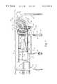
- FIG. 1is a side elevational view of a cushioning conversion machine and a curved output drive system for transferring a pad from the machine to a work platform in accordance with one embodiment of the present invention
- FIG. 2is a front elevational view of the cushioning conversion machine and output drive system of FIG. 1;
- FIG. 3is an enlarged side view of the output drive system
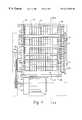
- FIG. 4is an enlarged front view of the output drive system
- FIG. 5is an illustration of the output drive system depicting the direction of rotation of the drive rollers.
- FIGS. 6A and 6Bare illustrations of a pad being transferred through the output drive system.
- FIGS. 1 and 2there is shown a cushioning conversion machine 10 for producing low density cushioning product with a curved output drive system 12 for transferring pads upwardly from the exit 14 of the machine to a work platform 16 of a dispensing table 18 .
- the machine 10includes a frame 20 to which are mounted a supply assembly 22 at the upstream end 24 of the frame for supplying stock material to be converted into a cushioning product, a conversion assembly 26 for converting the stock material into a continuous strip of cushioning product and a severing or cutting assembly 28 located generally between the conversion assembly and output drive system 12 at the downstream end 30 of the machine 10 for severing the strip into cushioning pads of the desired length.
- a supply assembly 22at the upstream end 24 of the frame for supplying stock material to be converted into a cushioning product
- a conversion assembly 26for converting the stock material into a continuous strip of cushioning product
- a severing or cutting assembly 28located generally between the conversion assembly and output drive system 12 at the downstream end 30 of the machine 10 for severing the strip into cushioning pads of the desired length.
- the stock supply assembly 22preferably includes a shaft 32 for supporting a roll of sheet-like stock material (not shown) and a number of rollers 34 for providing the stock material to the conversion assembly 26 .
- the stock materialmay consist of three superimposed webs of biodegradable, recyclable and reusable thirty-pound Kraft paper or the like rolled onto a hollow cylindrical tube.
- the conversion assembly 26includes a forming assembly 36 , such as a cooperating three dimensional wire former 38 and converging chute 40 as is shown in FIG. 1, and a feed assembly 42 including a pair of gears 44 for pulling the stock material through the forming assembly and feeding it through an outlet to the cutting assembly 28 and the curved output drive system 12 .
- the severing or cutting assembly 28may include one or more blades or other means acting to sever the continuous strip of padding at the appropriate times.
- the machine frame 20is supported on a cart 46 including a plurality of vertical support members or legs 48 , each ending in a caster 50 to permit the machine 10 to be moved with relative ease.
- the support members 48include a fixed upper portion 52 and a telescoping lower portion 54 which moves in and out of the interior of the fixed portion to permit vertical adjustment of the machine 10 and output drive system 12 under the dispensing table 18 and accurate alignment between the exit 56 of the output drive system and the passage 58 through the work platform 16 of the dispensing table 18 .
- the legs 60 of the dispensing table 18are also adjustable to facilitate alignment with and more preferably a connection between the curved output drive system 12 and the dispensing table.
- the output drive system 12forms the connection between the cushioning conversion machine 10 and the dispensing table 18 and includes a series of upper and lower rotating drive rollers 66 , 67 , respectively, spaced in an arc along a curved guide path 68 for engaging and transferring a pad from the machine exit 14 along the guide path and upwardly and through the passage 58 in the work platform 16 to present the formed and cut pad at or on the work platform.
- the upper and lower series of drive rollers 66 , 67are powered through a connection to a motor 70 and an assembly of gears 72 .
- the stock supply assembly 22supplies the stock material to the forming assembly 36 .
- the wire former 38 and converging conical chute 40 of the forming assembly 36cause inward rolling of the lateral edges of the sheet-like stock material to form a continuous strip having lateral pillow-like portions.
- the gears 44 of the feed assembly 42pull the stock material downstream through the machine and also coin the central band of the continuous strip to form the coined strip.
- the coined striptravels downstream from the feed assembly 42 it passes through the cutting assembly 28 to the output drive system 12 where it is frictionally engaged on its opposed upper and lower surfaces by the rotating upper and lower series of drive rollers 66 , 67 which transfer the pad along the guide in the direction of the work platform 16 .
- the series of drive rollers 66 , 67will continue to transfer the cut pad upwardly through the passage 58 in the work platform to deposit the formed and cut pad on the work platform for use as needed by the operator.
- the curved output drive system 12includes a frame 80 having parallel side walls 82 , 84 and a bottom wall 86 . Extending perpendicular to and between the side walls 82 and 84 are a pair of curved guide walls 88 , 90 defining the arcuate guide path 68 therebetween. Each guide wall 88 and 90 includes a number of openings 92 through which a circumferential portion of a drive roller protrudes into the guide path 68 to engage the surface of the pad.
- Each drive roller of the upper and lower series of drive rollers 66 , 67extends laterally for substantially the entire distance between the side walls 82 and 84 on a shaft 94 extending through each side wall and further includes a number of axially separated circumferential channels or grooves each serving to retain an elastomeric O-ring 93 for improving the ability of a drive roller to frictionally engage a pad.
- the shafts 94are positioned and the rollers are sized so that an appropriate section of each drive roller protrudes through a corresponding opening 92 in the guide walls 88 and 90 to effectively engage and transfer a pad through the guide path 68 .
- the distances between the outer peripheries of the opposed upper and lower series of drive roller 66 , 67are less than the thickness of the pad passing therebetween, thereby sufficiently compressing the pad to permit the transfer thereof.
- the shaft 94 of the first drive roller 96 in the lower series of drive rollers 67extends through the side wall 82 to a clutch mechanism 98 for selectively coupling the first drive roller 96 with the motor 70 .
- Rotational motionis transferred from the motor 70 mounted to the bottom wall 86 to the first drive roller 96 through a drive pulley 102 connected to the motor shaft 104 and a belt 106 extending between the drive pulley and a pulley 100 connected to the clutch mechanism 98 .
- a pair of gears 108 and 110are connected to the distal end of the shaft 94 of the first drive roller 96 extending through side wall 84 .
- the shaft 94 of the second drive roller 114 of the lower series of drive rollers 67extends through side wall 84 for connection to a gear 116 in communication with the gear 110 of the first drive roller 96 through a transfer gear 118 rotatably mounted on a shaft 120 extending from the side wall 84 . Consequently, rotation of the first drive roller 96 causes rotation of the second drive roller 114 in the same direction through common connection with the transfer gear 118 . Similarly, rotational motion is transferred from drive roller 114 to the next drive roller, drive roller 122 , and so on for all of the drive rollers of the lower series 67 .
- Rotational motionis transferred to the upper series of drive rollers 66 by an enmeshed connection between the gear 108 associated with the first drive roller 96 of the lower series of drive rollers 67 and a gear 124 adapted to drive the first drive roller 132 of the upper series of rollers 66 through the shaft 94 .
- Rotational motionis transferred to the second drive roller 138 though a transfer gear 126 rotatably mounted on a shaft 128 extending from the side wall 84 and enmeshed with the gear 125 of the drive roller 132 and gear 134 connected to drive roller 138 through an associated shaft 94 .
- the drive roller 138causes rotation of the drive roller 140 through the transfer gear 142 in the same manner.
- the gear 108transfers rotation from the first drive roller 96 of the lower series of drive rollers 67 to the drive roller 136 of the upper series of drive rollers 66 directly through the gear 124 connected to the drive roller 136 , the direction of rotation of the upper series of drive rollers 66 is opposite that of the lower series of drive rollers 67 (see directional arrows in FIG. 5 ). Therefore, the upper and lower series of drive rollers 66 , 67 will act cooperatively in urging a pad compressed therebetween in the same direction through the guide path 68 , namely a direction away from the cushioning conversion machine to the dispensing table 18 .
- Each of the sensors 146 and 148may be conventional sensors for detecting the presence or absence of a pad adjacent the sensor.
- An example of a suitable sensorwould be an optical sensor with a corresponding retro-reflector positioned at an opposite side of the path 68 from the optical sensor.
- the sensor 146is positioned near the exit portion 56 of the system 12 and senses the presence or absence of a pad at the exit portion 56 .
- the output of the sensor 146controls the clutch mechanism 98 , preferably in combination with a timer or delay circuit (hereinafter the timer and sensor 146 are collectively referenced by the reference numeral 146 ), so that once a pad is sensed at the exit portion 56 by the sensor 146 , transfer of the pad will continue for a short period of time, as controlled by the timer, sufficient to permit an adequate amount of pad to emerge from the passage 58 in the work platform 16 that an operator can easily access and remove the pad.
- a timer or delay circuithereinafter the timer and sensor 146 are collectively referenced by the reference numeral 146
- the clutch mechanism 98is disengaged, thereby discontinuing movement of the upper and lower series of drive rollers 66 and 67 and ceasing movement of the pad.
- the clutch mechanism 98will remain disengaged until an operator removes the pad from the output drive system 12 , and such removal is detected by the sensor 146 .
- the output of the sensor 146may also be provided to the machine 10 which can use the information to control production of pads such that when a pad is removed from the output drive system 12 , as detected by the sensor 146 , the machine will automatically produce another pad.
- the automatically produced padwill be conveyed by the output drive system 12 (as the clutch mechanism 98 is engaged since the sensor 146 is not blocked by a pad) to begin to emerge from the work platform 16 whereupon the sensor will detect the pad and the clutch mechanism 98 will be disengaged (after a short time period) and the machine will again wait for the partially emerged pad to be removed by an operator before producing another pad.
- the output of the sensor 146is used by the machine 10 in controlling the automatic production of a pad as a pad is used by an operator, and especially when the pad length may be short, in relation to the length of the guide path 68 , it is preferable to locate the sensor 148 midway between the machine exit 14 and the exit portion 56 of the output drive system 12 and to provide the output of the sensor 146 to the machine 10 . As a pad progresses past the sensor 148 , the sensor 148 detects the presence of the pad and reports the fact to the machine 10 . The machine 10 examines the output of the sensor 148 , when the sensor 146 has reported that a pad has been removed, to ensure that another pad is not already in the output drive system 12 before producing a further pad.
- the sensor 148is also provided with a timer or delay circuit so that the timer 148 will continue to indicate the presence of another pad in the output drive system, even after the pad has progressed past the sensor 148 to give the pad adequate time to reach the sensor 146 located at the output. This ensures that the machine will not produce a pad when a short pad is in the output drive system, but located wholly within the “blindspot” between the sensors 146 and 148 .
- the motor 70 or clutch mechanism 98may be controlled by a process controller or similar circuity in the cushioning conversion machine 10 to cause the upper and lower drive rollers 66 and 67 to operate either continuously or only while a pad is being produced and a short period thereafter adequate to transfer the pad to the dispensing table 18 .
- the motor 70 or clutch mechanism 98may also be controlled to pause movement of the drive rollers during a cutting operation by the cutting assembly 28 . In an instance where pads are to be produced which may be of the same length or longer than the guide path 68 , it is desirable that the process controller of the cushioning conversion machine cause the clutch mechanism 98 to remain engaged whenever the feed assembly 42 is operating.
- FIGS. 6A and 6Battention is directed to the pad 150 shown in FIGS. 6A and 6B.
- the pad 150Once the pad 150 leaves the machine exit 14 it enters the curved output drive system 12 at entry portion 152 and is compressed and engaged by opposed drive rollers 96 and 136 (see FIG. 6 A).
- the rotation of the drive rollers 96 and 136causes the pad 150 to move through the guide path 68 in the direction of arrow 154 (see FIG. 6 B).
- Continued rotation of the drive rollers in the upper and lower series of drive rollers 66 , 67moves the pad 150 further along the curved guide path 68 , past the sensor 148 , and causing pad 150 to pass the sensor 146 .
- the clutch mechanism 98will remain engaged to further drive the pad 150 to emerge from the exit port 156 for a distance sufficient to allow an operator to grasp the pad and remove it, when needed, from the output drive system 12 .
- the clutchis disengaged and the pad 150 remains partially emerged from the output drive system 12 and the work platform 16 of the dispensing table 18 to present the pad to the operator at the work platform (FIG. 1 ).
Landscapes
- Making Paper Articles (AREA)
Abstract
Description
Claims (15)
Priority Applications (10)
| Application Number | Priority Date | Filing Date | Title |
|---|---|---|---|
| US08/672,856US6217501B1 (en) | 1996-06-28 | 1996-06-28 | Cushioning conversion machine |
| AU19825/97AAU1982597A (en) | 1996-02-28 | 1997-02-28 | Cushioning conversion machine |
| EP97907960AEP0889779B1 (en) | 1996-02-28 | 1997-02-28 | Cushioning conversion method and machine |
| CN 97194143CN1216952A (en) | 1996-02-28 | 1997-02-28 | Cushioning conversion machine |
| PCT/US1997/003218WO1997031773A2 (en) | 1996-02-28 | 1997-02-28 | Cushioning conversion machine |
| JP9531178AJP2000506076A (en) | 1996-02-28 | 1997-02-28 | Buffer converter |
| KR1019980706803AKR19990087388A (en) | 1995-02-28 | 1997-02-28 | Buffer conversion device |
| CA 2247371CA2247371A1 (en) | 1996-02-28 | 1997-02-28 | Cushioning conversion machine |
| DE69714026TDE69714026T2 (en) | 1996-02-28 | 1997-02-28 | UPHOLSTERY CONVERSION METHOD AND MACHINE |
| MX9807042AMX9807042A (en) | 1996-02-28 | 1998-08-28 | Cushioning conversion machine |
Applications Claiming Priority (1)
| Application Number | Priority Date | Filing Date | Title |
|---|---|---|---|
| US08/672,856US6217501B1 (en) | 1996-06-28 | 1996-06-28 | Cushioning conversion machine |
Publications (1)
| Publication Number | Publication Date |
|---|---|
| US6217501B1true US6217501B1 (en) | 2001-04-17 |
Family
ID=24700304
Family Applications (1)
| Application Number | Title | Priority Date | Filing Date |
|---|---|---|---|
| US08/672,856Expired - Fee RelatedUS6217501B1 (en) | 1995-02-28 | 1996-06-28 | Cushioning conversion machine |
Country Status (1)
| Country | Link |
|---|---|
| US (1) | US6217501B1 (en) |
Cited By (17)
| Publication number | Priority date | Publication date | Assignee | Title |
|---|---|---|---|---|
| US6503182B2 (en)* | 2001-03-29 | 2003-01-07 | Zsolt Design Engineering, Inc. | Compact apparatus and system for creating and dispensing cushioning dunnage |
| US20030087741A1 (en)* | 2001-03-29 | 2003-05-08 | Zsolt Toth | Method, apparatus and system for making cushioning product, and roll tensioner therefor |
| US6626813B1 (en)* | 1997-10-27 | 2003-09-30 | Ranpak Corp. | Cushioning conversion system and method for making a coil of cushioning product |
| US6673001B2 (en) | 2001-03-29 | 2004-01-06 | Zsolt Toth | Compact apparatus and system for creating and dispensing cushioning dunnage |
| US20040192531A1 (en)* | 2003-02-14 | 2004-09-30 | Hans Meessen | Dunnage conversion system with multi-ply web detection |
| US20040266598A1 (en)* | 2001-03-29 | 2004-12-30 | Zsolt Toth | Cushioning conversion system and method |
| US20070117703A1 (en)* | 2005-11-22 | 2007-05-24 | Sealed Air Corporation | Machine and method for converting a web of material into dunnage |
| US20070122575A1 (en)* | 2002-09-17 | 2007-05-31 | Storopack Hans Reichenecker Gmbh | Cushioning product and method and apparatus for making same |
| US20110053748A1 (en)* | 2009-08-28 | 2011-03-03 | Pregis Innovative Packaging, Inc. | Reconfigurable dunnage handler |
| EP2719528A1 (en)* | 2012-10-12 | 2014-04-16 | Storopack Hans Reichenecker GmbH | Device for producing a cushioning product from paper |
| US20140106954A1 (en)* | 2012-10-12 | 2014-04-17 | Storopack Hans Reichenecker Gmbh | Device for making a paper pad product |
| US20150352802A1 (en)* | 2014-06-09 | 2015-12-10 | Storopack, Inc. | Protective packaging work station |
| US9884465B2 (en)* | 2011-06-16 | 2018-02-06 | Ranpak Corp. | Dunnage conversion machine and method with downstream feed monitor |
| WO2019070511A1 (en)* | 2017-10-02 | 2019-04-11 | Ranpak Corp. | FEED OUTPUT CHU FOR A WASTE CONVERSION MACHINE |
| US20200238652A1 (en)* | 2017-07-25 | 2020-07-30 | Storopack Hans Reichenecker Gmbh | Device For Dispensing A Padding Material For Packaging Purposes |
| US20210299990A1 (en)* | 2017-05-11 | 2021-09-30 | Pregis Innovative Packaging Llc | Dunnage apparatus carton filler |
| US11225043B2 (en)* | 2017-07-14 | 2022-01-18 | Sprick GmbH Bielefelder Papier—und Wellpappenwerke & Co. | Apparatus for the manual or machine-made production of a tube-like packaging material and packing station |
Citations (19)
| Publication number | Priority date | Publication date | Assignee | Title |
|---|---|---|---|---|
| US4410315A (en)* | 1980-10-03 | 1983-10-18 | Beloit Corporation | Low velocity trim removal means and method |
| US4462287A (en) | 1982-12-02 | 1984-07-31 | Crown Zellerbach Corporation | Apparatus for culling cant ends |
| US4555105A (en) | 1983-04-15 | 1985-11-26 | At&T Technologies, Inc. | Method and apparatus utilizing magnetically coupled rollers to feed sheets |
| US4690344A (en)* | 1986-02-18 | 1987-09-01 | Yazaki Industrial Chemical Co., Ltd. | Roll holder |
| FR2624830A1 (en) | 1987-12-22 | 1989-06-23 | Monarch Marking Systems Inc | LABEL STACK AND STACKING METHOD THEREOF |
| US4968291A (en)* | 1989-05-03 | 1990-11-06 | Ranpak Corp. | Stitching gear assembly having perforating projections thereon, for use in converter adapted to produce pad-like cushioning material, and method |
| US4976600A (en) | 1988-06-21 | 1990-12-11 | Apv Baker Pty Ltd. | Bread molders |
| WO1992005948A1 (en) | 1990-10-05 | 1992-04-16 | Ranpak Corporation | Downsized cushioning dunnage conversion machine and packaging systems employing the same |
| EP0523382A2 (en) | 1991-06-17 | 1993-01-20 | Sealed Air Corporation | Apparatus for fabricating dunnage material from continuous web material |
| US5211620A (en)* | 1991-11-01 | 1993-05-18 | Ranpak Corp. | Edge-tension controlling device for a cushioning conversion machine |
| US5292238A (en) | 1992-05-20 | 1994-03-08 | Mama Irene's Specialty Candies, Inc. | Apparatus for making cotton candy and preparing it for packaging |
| US5322477A (en)* | 1990-10-05 | 1994-06-21 | Ranpak Corp. | Downsized cushioning dunnage conversion machine and packaging systems employing the same |
| US5387173A (en)* | 1992-12-22 | 1995-02-07 | Ranpak Corp. | Fan-folded stock material for use with a cushioning conversion machine |
| WO1995013914A1 (en) | 1993-11-19 | 1995-05-26 | Ranpak Corp. | A packaging program |
| WO1995014569A1 (en) | 1993-11-23 | 1995-06-01 | Ranpak Corp. | Dispensing table for a cushioning conversion machine |
| WO1995028276A1 (en) | 1994-04-15 | 1995-10-26 | Ranpak Corp. | A cushion producing machine |
| US5542232A (en)* | 1993-11-19 | 1996-08-06 | Ranpak Corp. | Transitional slide for use with a cushion-creating machine |
| US5571067A (en)* | 1993-11-19 | 1996-11-05 | Ranpak Corp. | Cushioning conversion machine including a length measuring device |
| US5637071A (en)* | 1993-08-19 | 1997-06-10 | Ranpak Corp. | Dispensing table for a cushioning conversion machine |
- 1996
- 1996-06-28USUS08/672,856patent/US6217501B1/ennot_activeExpired - Fee Related
Patent Citations (26)
| Publication number | Priority date | Publication date | Assignee | Title |
|---|---|---|---|---|
| US4410315A (en)* | 1980-10-03 | 1983-10-18 | Beloit Corporation | Low velocity trim removal means and method |
| US4462287A (en) | 1982-12-02 | 1984-07-31 | Crown Zellerbach Corporation | Apparatus for culling cant ends |
| US4555105A (en) | 1983-04-15 | 1985-11-26 | At&T Technologies, Inc. | Method and apparatus utilizing magnetically coupled rollers to feed sheets |
| US4690344A (en)* | 1986-02-18 | 1987-09-01 | Yazaki Industrial Chemical Co., Ltd. | Roll holder |
| FR2624830A1 (en) | 1987-12-22 | 1989-06-23 | Monarch Marking Systems Inc | LABEL STACK AND STACKING METHOD THEREOF |
| US4976600A (en) | 1988-06-21 | 1990-12-11 | Apv Baker Pty Ltd. | Bread molders |
| US4968291A (en)* | 1989-05-03 | 1990-11-06 | Ranpak Corp. | Stitching gear assembly having perforating projections thereon, for use in converter adapted to produce pad-like cushioning material, and method |
| WO1990013414A1 (en) | 1989-05-03 | 1990-11-15 | Ranpak Corp. | Stitching gear assembly having perforating projections thereon, for use in converter adapted to produce pad-like cushioning material, and method |
| WO1992005948A1 (en) | 1990-10-05 | 1992-04-16 | Ranpak Corporation | Downsized cushioning dunnage conversion machine and packaging systems employing the same |
| US5123889A (en)* | 1990-10-05 | 1992-06-23 | Ranpak Corporation | Downsized cushioning dunnage conversion machine and cutting assemblies for use on such a machine |
| US5468208A (en)* | 1990-10-05 | 1995-11-21 | Ranpak Corp. | Downsized cushioning dunnage conversion machine and packaging systems employing the same |
| US5322477A (en)* | 1990-10-05 | 1994-06-21 | Ranpak Corp. | Downsized cushioning dunnage conversion machine and packaging systems employing the same |
| EP0523382A2 (en) | 1991-06-17 | 1993-01-20 | Sealed Air Corporation | Apparatus for fabricating dunnage material from continuous web material |
| US5203761A (en)* | 1991-06-17 | 1993-04-20 | Sealed Air Corporation | Apparatus for fabricating dunnage material from continuous web material |
| US5327805A (en)* | 1991-06-17 | 1994-07-12 | Sealed Air Corporation | Apparatus for severing continuous sheet material |
| US5297919A (en)* | 1991-06-17 | 1994-03-29 | Sealed Air Corporation | Apparatus for transporting and storing sheet material |
| US5211620A (en)* | 1991-11-01 | 1993-05-18 | Ranpak Corp. | Edge-tension controlling device for a cushioning conversion machine |
| US5292238A (en) | 1992-05-20 | 1994-03-08 | Mama Irene's Specialty Candies, Inc. | Apparatus for making cotton candy and preparing it for packaging |
| US5387173A (en)* | 1992-12-22 | 1995-02-07 | Ranpak Corp. | Fan-folded stock material for use with a cushioning conversion machine |
| US5487717A (en)* | 1993-05-21 | 1996-01-30 | Ranpak Corp. | Dispensing table for a cushioning conversion machine |
| US5637071A (en)* | 1993-08-19 | 1997-06-10 | Ranpak Corp. | Dispensing table for a cushioning conversion machine |
| WO1995013914A1 (en) | 1993-11-19 | 1995-05-26 | Ranpak Corp. | A packaging program |
| US5542232A (en)* | 1993-11-19 | 1996-08-06 | Ranpak Corp. | Transitional slide for use with a cushion-creating machine |
| US5571067A (en)* | 1993-11-19 | 1996-11-05 | Ranpak Corp. | Cushioning conversion machine including a length measuring device |
| WO1995014569A1 (en) | 1993-11-23 | 1995-06-01 | Ranpak Corp. | Dispensing table for a cushioning conversion machine |
| WO1995028276A1 (en) | 1994-04-15 | 1995-10-26 | Ranpak Corp. | A cushion producing machine |
Cited By (41)
| Publication number | Priority date | Publication date | Assignee | Title |
|---|---|---|---|---|
| US6626813B1 (en)* | 1997-10-27 | 2003-09-30 | Ranpak Corp. | Cushioning conversion system and method for making a coil of cushioning product |
| US7335151B2 (en) | 2001-03-29 | 2008-02-26 | Zsolt Design Engineering, Inc. | Method, apparatus and system for making cushioning product, and roll tensioner therefor |
| US20070117705A1 (en)* | 2001-03-29 | 2007-05-24 | Zsolt Toth | Cushioning conversion system and method |
| US6673001B2 (en) | 2001-03-29 | 2004-01-06 | Zsolt Toth | Compact apparatus and system for creating and dispensing cushioning dunnage |
| US20040043883A1 (en)* | 2001-03-29 | 2004-03-04 | Zsolt Toth | Compact apparatus and system for creating and dispensing cushioning dunnage |
| US6503182B2 (en)* | 2001-03-29 | 2003-01-07 | Zsolt Design Engineering, Inc. | Compact apparatus and system for creating and dispensing cushioning dunnage |
| US20040266598A1 (en)* | 2001-03-29 | 2004-12-30 | Zsolt Toth | Cushioning conversion system and method |
| US7022060B2 (en) | 2001-03-29 | 2006-04-04 | Zsolt Design Engineering, Inc. | Method, apparatus and system for making cushioning product, and roll tensioner therefor |
| US20060135336A1 (en)* | 2001-03-29 | 2006-06-22 | Zsolt Toth | Method, apparatus and system for making cushioning product, and roll tensioner therefor |
| US7163503B2 (en) | 2001-03-29 | 2007-01-16 | Zsolt Design Engineering, Inc. | Compact apparatus and system for creating and dispensing cushioning dunnage |
| US7479100B2 (en) | 2001-03-29 | 2009-01-20 | Zsolt Design Engineering, Inc. | Cushioning conversion system and method |
| US20030087741A1 (en)* | 2001-03-29 | 2003-05-08 | Zsolt Toth | Method, apparatus and system for making cushioning product, and roll tensioner therefor |
| US20070117704A1 (en)* | 2001-03-29 | 2007-05-24 | Zsolt Toth | Compact apparatus and system for creating and dispensing cushioning dunnage |
| US7172548B2 (en) | 2001-03-29 | 2007-02-06 | Zsolt Design Engineering, Inc. | Cushioning conversion system and method |
| US7347809B2 (en) | 2001-03-29 | 2008-03-25 | Zsolt Design Engineering, Inc. | Compact apparatus and system for creating and dispensing cushioning dunnage |
| US8491453B2 (en)* | 2002-09-17 | 2013-07-23 | Storopack Hans Reichenecker Gmbh | Cushioning product and method and apparatus for making same |
| US20080051277A1 (en)* | 2002-09-17 | 2008-02-28 | Storopack Hans Reichenecker Gmbh | Cushioning product and method and apparatus for making same |
| US20080058191A1 (en)* | 2002-09-17 | 2008-03-06 | Storopack Hans Reichenecker Gmbh | Cushioning product and method and apparatus for making same |
| US20070122575A1 (en)* | 2002-09-17 | 2007-05-31 | Storopack Hans Reichenecker Gmbh | Cushioning product and method and apparatus for making same |
| US7972258B2 (en)* | 2002-09-17 | 2011-07-05 | Storopack Hans Reichenecker Gmbh | Cushioning product and method and apparatus for making same |
| US8114490B2 (en) | 2002-09-17 | 2012-02-14 | Storopack Hans Reichenecker Gmbh | Cushioning product and method and apparatus for making same |
| US20040192531A1 (en)* | 2003-02-14 | 2004-09-30 | Hans Meessen | Dunnage conversion system with multi-ply web detection |
| US20070117703A1 (en)* | 2005-11-22 | 2007-05-24 | Sealed Air Corporation | Machine and method for converting a web of material into dunnage |
| US20110053748A1 (en)* | 2009-08-28 | 2011-03-03 | Pregis Innovative Packaging, Inc. | Reconfigurable dunnage handler |
| US8845504B2 (en)* | 2009-08-28 | 2014-09-30 | Pregis Innovative Packaging, Inc. | Reconfigurable dunnage handler |
| US9884465B2 (en)* | 2011-06-16 | 2018-02-06 | Ranpak Corp. | Dunnage conversion machine and method with downstream feed monitor |
| CN103722777A (en)* | 2012-10-12 | 2014-04-16 | 施托奥皮克汉斯赖兴埃克有限公司 | Device for producing a cushioning product from paper |
| US20140106954A1 (en)* | 2012-10-12 | 2014-04-17 | Storopack Hans Reichenecker Gmbh | Device for making a paper pad product |
| US20140113794A1 (en)* | 2012-10-12 | 2014-04-24 | Storopack Hans Reichenecker Gmbh | Device for making a paper pad product |
| EP2719528A1 (en)* | 2012-10-12 | 2014-04-16 | Storopack Hans Reichenecker GmbH | Device for producing a cushioning product from paper |
| US20150352802A1 (en)* | 2014-06-09 | 2015-12-10 | Storopack, Inc. | Protective packaging work station |
| US20210299990A1 (en)* | 2017-05-11 | 2021-09-30 | Pregis Innovative Packaging Llc | Dunnage apparatus carton filler |
| US11926119B2 (en)* | 2017-05-11 | 2024-03-12 | Pregis Innovative Packaging Llc | Dunnage apparatus carton filler |
| US11225043B2 (en)* | 2017-07-14 | 2022-01-18 | Sprick GmbH Bielefelder Papier—und Wellpappenwerke & Co. | Apparatus for the manual or machine-made production of a tube-like packaging material and packing station |
| US20200238652A1 (en)* | 2017-07-25 | 2020-07-30 | Storopack Hans Reichenecker Gmbh | Device For Dispensing A Padding Material For Packaging Purposes |
| US11951706B2 (en)* | 2017-07-25 | 2024-04-09 | Storopack Hans Reichenecker Gmbh | Device for dispensing a padding material for packaging purposes |
| US20210023808A1 (en)* | 2017-10-02 | 2021-01-28 | Ranpak Corp. | Powered outlet chute for dunnage conversion machine |
| CN111163926A (en)* | 2017-10-02 | 2020-05-15 | 兰帕克公司 | Driven output chute for dunnage converters |
| CN111163926B (en)* | 2017-10-02 | 2022-03-22 | 朗派公司 | Driven output chute for dunnage converters |
| US11718060B2 (en)* | 2017-10-02 | 2023-08-08 | Ranpak Corp. | Powered outlet chute for dunnage conversion machine |
| WO2019070511A1 (en)* | 2017-10-02 | 2019-04-11 | Ranpak Corp. | FEED OUTPUT CHU FOR A WASTE CONVERSION MACHINE |
Similar Documents
| Publication | Publication Date | Title |
|---|---|---|
| EP0889779B1 (en) | Cushioning conversion method and machine | |
| WO1997031773A9 (en) | Cushioning conversion machine | |
| US6217501B1 (en) | Cushioning conversion machine | |
| US11325340B2 (en) | Dunnage conversion machine and method | |
| US5749821A (en) | Cushioning conversion system for converting paper stock into cushioning material with a staging area and a pick and place assembly | |
| CA2494020C (en) | Compact apparatus and system for creating and dispensing cushioning dunnage | |
| US6168560B1 (en) | Cushioning conversion machine and method with pad transferring device | |
| EP1392498B1 (en) | Compact apparatus and system for creating and dispensing cushioning dunnage | |
| US5778631A (en) | Automated cushioning producing and dispening system | |
| AU2002244237A1 (en) | Compact apparatus and system for creating and dispensing cushioning dunnage | |
| EP0831990B1 (en) | Loading assembly and method for cushioning conversion machine | |
| US5735784A (en) | Loading assembly for a cushioning conversion machine | |
| US7041043B2 (en) | Cushioning conversion machine and method with plural constant entry rollers and moving blade shutter | |
| EP0747208A1 (en) | Cushioning conversion machine with wheel paper former | |
| AU2008304463B9 (en) | Dunnage conversion machine, method and dunnage product |
Legal Events
| Date | Code | Title | Description |
|---|---|---|---|
| AS | Assignment | Owner name:RANPAK CORP., OHIO Free format text:ASSIGNMENT OF ASSIGNORS INTEREST;ASSIGNORS:SIMMONS, JAMES A. JR.;HARDING, JOSEPH JAMES;REEL/FRAME:008163/0715 Effective date:19960826 | |
| AS | Assignment | Owner name:GENERAL ELECTRIC CAPITAL CORPORATION, AS AGENT, CO Free format text:SECURITY AGREEMENT;ASSIGNOR:RANPAK CORP.;REEL/FRAME:012418/0493 Effective date:20011228 | |
| AS | Assignment | Owner name:GENERAL ELECTRIC CAPITAL CORPORATION, CONNECTICUT Free format text:SECURITY AGREEMENT;ASSIGNOR:RANPAK CORP.;REEL/FRAME:014709/0832 Effective date:20040526 | |
| AS | Assignment | Owner name:SPECIAL SITUATIONS INVESTING GROUP, INC., NEW YORK Free format text:SECURITY AGREEMENT;ASSIGNOR:RANPAK CORP.;REEL/FRAME:015676/0883 Effective date:20040727 | |
| REMI | Maintenance fee reminder mailed | ||
| AS | Assignment | Owner name:GENERAL ELECTRIC CAPITAL CORPORATION, AS AGENT, CO Free format text:SECURITY INTEREST;ASSIGNOR:RANPAK CORP;REEL/FRAME:015861/0341 Effective date:20050317 | |
| LAPS | Lapse for failure to pay maintenance fees | ||
| STCH | Information on status: patent discontinuation | Free format text:PATENT EXPIRED DUE TO NONPAYMENT OF MAINTENANCE FEES UNDER 37 CFR 1.362 | |
| FP | Lapsed due to failure to pay maintenance fee | Effective date:20050417 | |
| AS | Assignment | Owner name:RANPAK CORP, OHIO Free format text:RELEASE OF SECURITY INTEREST;ASSIGNOR:SPECIAL SITUATIONS INVESTING GROUP, INC.;REEL/FRAME:016784/0231 Effective date:20041104 | |
| AS | Assignment | Owner name:GENERAL ELECTRIC CAPITAL CORPROATION, CONNECTICUT Free format text:SECURITY AGREEMENT;ASSIGNOR:RANPAK CORP.;REEL/FRAME:016945/0612 Effective date:20051214 | |
| AS | Assignment | Owner name:RANPAK CORP., OHIO Free format text:RELEASE OF SECURITY INTEREST;ASSIGNOR:GENERAL ELECTRIC CAPITAL CORPORATION;REEL/FRAME:016967/0696 Effective date:20051214 Owner name:RANPAK CORP., OHIO Free format text:RELEASE OF SECURITY INTEREST;ASSIGNOR:GENERAL ELECTRIC CAPITAL CORPORATION;REEL/FRAME:016976/0285 Effective date:20051214 Owner name:RANPAK CORP., OHIO Free format text:RELEASE OF SECURITY INTEREST;ASSIGNOR:GENERAL ELECTRIC CAPITAL CORPORATION;REEL/FRAME:016976/0302 Effective date:20051214 | |
| AS | Assignment | Owner name:RANPAK CORP., OHIO Free format text:RELEASE OF SECURITY INTEREST INTELLECTUAL PROPERTY COLLATERAL;ASSIGNOR:GENERAL ELECTRIC CAPITAL CORPORATION, AS AGENT;REEL/FRAME:020362/0864 Effective date:20071227 Owner name:RANPAK CORP.,OHIO Free format text:RELEASE OF SECURITY INTEREST INTELLECTUAL PROPERTY COLLATERAL;ASSIGNOR:GENERAL ELECTRIC CAPITAL CORPORATION, AS AGENT;REEL/FRAME:020362/0864 Effective date:20071227 | |
| AS | Assignment | Owner name:AMERICAN CAPITAL FINANCIAL SERVICES, INC., AS AGEN Free format text:FIRST LIEN PATENT SECURITY AGREEMENT;ASSIGNOR:RANPAK CORP.;REEL/FRAME:020690/0276 Effective date:20071227 | |
| AS | Assignment | Owner name:AMERICAN CAPITAL FINANCIAL SERVICES, INC., AS AGEN Free format text:SECOND LIEN PATENT SECURITY AGREEMENT;ASSIGNOR:RANPAK CORP.;REEL/FRAME:020497/0927 Effective date:20071227 |