US6217444B1 - Simulative golf game system and a method for providing a simulative golf game and a storage medium for storing a simulative golf game program - Google Patents
Simulative golf game system and a method for providing a simulative golf game and a storage medium for storing a simulative golf game programDownload PDFInfo
- Publication number
- US6217444B1 US6217444B1US08/935,017US93501797AUS6217444B1US 6217444 B1US6217444 B1US 6217444B1US 93501797 AUS93501797 AUS 93501797AUS 6217444 B1US6217444 B1US 6217444B1
- Authority
- US
- United States
- Prior art keywords
- game
- feet
- producing
- golfball
- spacing
- Prior art date
- Legal status (The legal status is an assumption and is not a legal conclusion. Google has not performed a legal analysis and makes no representation as to the accuracy of the status listed.)
- Expired - Lifetime
Links
Images


Classifications
- A—HUMAN NECESSITIES
- A63—SPORTS; GAMES; AMUSEMENTS
- A63F—CARD, BOARD, OR ROULETTE GAMES; INDOOR GAMES USING SMALL MOVING PLAYING BODIES; VIDEO GAMES; GAMES NOT OTHERWISE PROVIDED FOR
- A63F13/00—Video games, i.e. games using an electronically generated display having two or more dimensions
- A63F13/80—Special adaptations for executing a specific game genre or game mode
- A63F13/812—Ball games, e.g. soccer or baseball
- A63F13/10—
- A—HUMAN NECESSITIES
- A63—SPORTS; GAMES; AMUSEMENTS
- A63F—CARD, BOARD, OR ROULETTE GAMES; INDOOR GAMES USING SMALL MOVING PLAYING BODIES; VIDEO GAMES; GAMES NOT OTHERWISE PROVIDED FOR
- A63F13/00—Video games, i.e. games using an electronically generated display having two or more dimensions
- A63F13/40—Processing input control signals of video game devices, e.g. signals generated by the player or derived from the environment
- A63F13/44—Processing input control signals of video game devices, e.g. signals generated by the player or derived from the environment involving timing of operations, e.g. performing an action within a time slot
- A—HUMAN NECESSITIES
- A63—SPORTS; GAMES; AMUSEMENTS
- A63F—CARD, BOARD, OR ROULETTE GAMES; INDOOR GAMES USING SMALL MOVING PLAYING BODIES; VIDEO GAMES; GAMES NOT OTHERWISE PROVIDED FOR
- A63F13/00—Video games, i.e. games using an electronically generated display having two or more dimensions
- A63F13/45—Controlling the progress of the video game
- A—HUMAN NECESSITIES
- A63—SPORTS; GAMES; AMUSEMENTS
- A63F—CARD, BOARD, OR ROULETTE GAMES; INDOOR GAMES USING SMALL MOVING PLAYING BODIES; VIDEO GAMES; GAMES NOT OTHERWISE PROVIDED FOR
- A63F13/00—Video games, i.e. games using an electronically generated display having two or more dimensions
- A63F13/50—Controlling the output signals based on the game progress
- A63F13/53—Controlling the output signals based on the game progress involving additional visual information provided to the game scene, e.g. by overlay to simulate a head-up display [HUD] or displaying a laser sight in a shooting game
- A63F13/537—Controlling the output signals based on the game progress involving additional visual information provided to the game scene, e.g. by overlay to simulate a head-up display [HUD] or displaying a laser sight in a shooting game using indicators, e.g. showing the condition of a game character on screen
- A—HUMAN NECESSITIES
- A63—SPORTS; GAMES; AMUSEMENTS
- A63F—CARD, BOARD, OR ROULETTE GAMES; INDOOR GAMES USING SMALL MOVING PLAYING BODIES; VIDEO GAMES; GAMES NOT OTHERWISE PROVIDED FOR
- A63F13/00—Video games, i.e. games using an electronically generated display having two or more dimensions
- A63F13/55—Controlling game characters or game objects based on the game progress
- A63F13/57—Simulating properties, behaviour or motion of objects in the game world, e.g. computing tyre load in a car race game
- A63F13/573—Simulating properties, behaviour or motion of objects in the game world, e.g. computing tyre load in a car race game using trajectories of game objects, e.g. of a golf ball according to the point of impact
- A—HUMAN NECESSITIES
- A63—SPORTS; GAMES; AMUSEMENTS
- A63F—CARD, BOARD, OR ROULETTE GAMES; INDOOR GAMES USING SMALL MOVING PLAYING BODIES; VIDEO GAMES; GAMES NOT OTHERWISE PROVIDED FOR
- A63F2300/00—Features of games using an electronically generated display having two or more dimensions, e.g. on a television screen, showing representations related to the game
- A63F2300/30—Features of games using an electronically generated display having two or more dimensions, e.g. on a television screen, showing representations related to the game characterized by output arrangements for receiving control signals generated by the game device
- A63F2300/303—Features of games using an electronically generated display having two or more dimensions, e.g. on a television screen, showing representations related to the game characterized by output arrangements for receiving control signals generated by the game device for displaying additional data, e.g. simulating a Head Up Display
- A—HUMAN NECESSITIES
- A63—SPORTS; GAMES; AMUSEMENTS
- A63F—CARD, BOARD, OR ROULETTE GAMES; INDOOR GAMES USING SMALL MOVING PLAYING BODIES; VIDEO GAMES; GAMES NOT OTHERWISE PROVIDED FOR
- A63F2300/00—Features of games using an electronically generated display having two or more dimensions, e.g. on a television screen, showing representations related to the game
- A63F2300/60—Methods for processing data by generating or executing the game program
- A63F2300/63—Methods for processing data by generating or executing the game program for controlling the execution of the game in time
- A63F2300/638—Methods for processing data by generating or executing the game program for controlling the execution of the game in time according to the timing of operation or a time limit
- A—HUMAN NECESSITIES
- A63—SPORTS; GAMES; AMUSEMENTS
- A63F—CARD, BOARD, OR ROULETTE GAMES; INDOOR GAMES USING SMALL MOVING PLAYING BODIES; VIDEO GAMES; GAMES NOT OTHERWISE PROVIDED FOR
- A63F2300/00—Features of games using an electronically generated display having two or more dimensions, e.g. on a television screen, showing representations related to the game
- A63F2300/60—Methods for processing data by generating or executing the game program
- A63F2300/64—Methods for processing data by generating or executing the game program for computing dynamical parameters of game objects, e.g. motion determination or computation of frictional forces for a virtual car
- A—HUMAN NECESSITIES
- A63—SPORTS; GAMES; AMUSEMENTS
- A63F—CARD, BOARD, OR ROULETTE GAMES; INDOOR GAMES USING SMALL MOVING PLAYING BODIES; VIDEO GAMES; GAMES NOT OTHERWISE PROVIDED FOR
- A63F2300/00—Features of games using an electronically generated display having two or more dimensions, e.g. on a television screen, showing representations related to the game
- A63F2300/80—Features of games using an electronically generated display having two or more dimensions, e.g. on a television screen, showing representations related to the game specially adapted for executing a specific type of game
- A63F2300/8011—Ball
Definitions
- the present inventionrelates to a simulative golf game system, a method for providing a simulative golf game, and a computer readable storage medium, such as optical disk, magnetic disk, cassette type storage medium including semiconductor memory, for storing a simulative golf game program.
- a computer readable storage mediumsuch as optical disk, magnetic disk, cassette type storage medium including semiconductor memory
- simulative game systemshave been proposed. These systems are generally grouped into personal-use systems comprised of a special home appliance and a television monitor, and commercial-use systems comprised of special commercial equipment, a personal computer or work station, a display and an audio output machine. Any of these systems is provided with a controller operable by a player, a storage medium in which a game program is stored, a CPU for controlling generation of audio sounds and images based on the game program, a processor for generating images, a processor for generating audio sounds, a CRT for displaying the images, and a speaker for outputting the audio sounds.
- CD-ROMs, semiconductor memories and cassettes having built-in semiconductor memoriesare frequently used as a storage medium.
- the simulative game screen imageincludes a controllable object image which changes according to an operation of the controller and a background image which is still or suitably changes according to the operated state of the object.
- the background imagemay be further classified into one which gives a game player a visual change, i.e., mere background, and one which is used as conditions to obtain an outcome, e.g., points, for the game player.
- simulative golf gamesthere are simulative golf games.
- a simulative golf gameusually, by displaying an image of a golf course and an image of a golfer on a display screen of a television monitor, a golf game space is formed on the display screen.
- the golfer in the golf game spaceis visually moved according to an operation of a controller by the game player, and a golfball is driven by a club held by the golfer.
- the driven ballvisually flies in a direction of depth in the golf game space.
- golfis simulatively and visually executed in the golf game space in the same manner as man actually plays.
- golfis visually executed by suitably changing images displayed on the television monitor according to the operation of the controller by the game player.
- the image of the golf courseis related to the height data of the golf course. Based on the operation of the controller by the game player and the height data of the golf course, how far the golfball is going to be moved in the golf game space is calculated, and this calculation result is displayed as an image. For example, the golf ball is displayed in such a manner that it moves on the image information, representing the configuration of the golf course according, to the operation by the golf player.
- the game playercan simulatively and visually enjoy the golf game by operating the controller.
- the controllercan simulatively and visually enjoy the golf game by operating the controller.
- there is a demand for more a realistic golf gameFor example, in actual golf, the trajectory of a golfball largely changes depending upon a stance. It will be seen that the golf game becomes more real if the golfball trajectory changes with a variation in the stance.
- a simulative golf game systemcomprises an operation unit for generating an operation signal controlling a stance setting in accordance with an operation of a player, a game image producing unit for producing a game image having a guide image representing a stance setting in accordance with an operation signal from the operation unit, and a display unit for displaying a generated game image having a guide image.
- a method for providing a simulative golf game in a system provided with an operation unit to be operated by a player to generate an operation signal and a display unit on which a game image is displayedcomprises the steps of receiving an operation signal controlling a stance setting from the operation unit, generating a game image having a guide image representing a stance setting in accordance with the operation signal, and displaying a produced game image having a guide image indicating a stance setting.
- a computer readable storage mediumstoring a simulative golf game program which renders a computer to execute the procedures of receiving an operation signal controlling a stance setting from an operation unit to be operated by a player, producing a game image having a guide image indicating a stance setting in accordance with the operation signal, and displaying a generated game image having a guide image indicating a stance setting a display unit.
- a simulative golf game system of the present inventionprovides a game image having a guide image indicating a stance setting which is adjusted by the game player. Accordingly, the game player can easily recognize based on which stance is effected how the game is going play and feel more as if he were actually playing golf
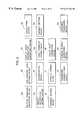
- FIG. 1is a block diagram showing a construction of a simulative golf game system embodying the present invention
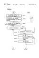
- FIG. 2is a diagram showing an arrangement of operating devices in a CPU of the simulative golf game system
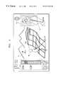
- FIG. 3is a diagram showing an example of screen display of the simulative golf game system
- FIGS. 4 to 6are flowcharts showing an operation sequence of a main routine of a game program
- FIGS. 7 and 8are flowcharts showing an operation sequence of a stance setting routine
- FIGS. 9 and 10are flowcharts showing an operation sequence of a stance width setting routine
- FIGS. 11 and 12are flowcharts showing an operation sequence of a ball position setting routine
- FIGS. 15 and 16are flowcharts showing an operation sequence of a stroke routine
- FIGS. 17A and 17Bare diagrams showing a relationship between an analog stick and a stance
- FIGS. 18A and 18Bare diagrams showing a relationship between a stance width and a power meter.
- FIGS. 19A and 19Bare diagrams showing display examples of the power meter during the stroke processing.
- FIG. 1A. Construction of Game System (FIG. 1)
- FIG. 1shows an overall construction of a simulative golf game system according to one embodiment of the invention.
- the game systemincludes a main unit 1 , a television monitor 2 for displaying images of a game, an amplifying circuit 3 and a speaker 4 for outputting audio sounds of the game, and a storage medium 5 for storing a game program and game data in connection with images, and audio sounds.
- a storage medium 5for storing a game program and game data in connection with images, and audio sounds.
- the storage medium 5a so-called ROM cassette, optical disk, flexible disk, or the like, in which the above-mentioned program and game data are recorded is used.
- the main unit 1has buses 7 including an address bus, a data bus and a control bus that are connected to a CPU 6 .
- the buses 7interconnect a RAM 8 , interface circuits 9 , 10 , a signal processor 11 , an image processor 12 , and interface circuits 13 , 14 .
- the interface circuit 10connects a controller 16 via an operation information interface circuit 15 .
- Digital-to-analog (D/A) converters 17 , 18are connected via the interface circuits 13 , 14 , respectively, to the buses 7 .
- D/ADigital-to-analog
- a memory portion 19is defined by the RAM 8 , the interface circuit 9 and the storage medium 5 .
- a controlling portion 20is defined by the CPU 6 , the signal processor 11 and the image processor 12 to control the progress of the game.
- An operable input portion 21is defined by the interface circuit 10 , the operation information interface circuit 15 and the controller 16 .
- An image display portion 22is defined by the television monitor 2 , the interface circuit 13 and the D/A converter 17 .
- An audio output portion 23is defined by the amplifying circuit 3 , the speaker 4 , the interface circuit 14 and the D/A converter 18 .
- the game systemis changeable depending on its application. Specifically, in the case that the game system is applied for home use, the television monitor 2 , the amplifying circuit 3 and the speaker 4 are arranged separately from the main unit 1 .
- FIG. 1shows an arrangement for the home use.
- FIG. 1In the case that the game system is applied for commercial use, all the elements shown in FIG. 1 are integrally assembled in a single housing.
- the television monitor 2may be replaced with a monitor of the computer.
- the function of the image processor 12may be accomplished by a part of the game program stored in the storage medium 5 or hardware on an extensible board mounted on an extensible slot of the computer.
- the function of the RAM 8may be accomplished by a memory of the computer or of an extensible memory.
- the interface circuits 9 , 10 , 13 , 14 , the D/A converters 17 , 18 , the operation information interface circuit 15correspond to the hardware on the extensible board mounted on the extensible slot of the computer.
- the signal processor 11mainly executes calculations in a three-dimensional space, calculations for transformation of positions in the three-dimensional space into positions in a pseudo three-dimensional space, light source calculation processing, generation of audio data and other processing.
- the image processor 12executes, based on calculation results of the signal processor 11 , processing of writing image data to be displayed into the RAM 8 , e.g., writing texture data in an area of the RAM 8 designated for a polygon.
- the controller 16includes a start button 16 a , A-button 16 b , B-button 16 c , a cross key 16 d , an analog stick 16 e , a left trigger button 16 f , a right trigger button 16 g , a C1-button 16 h , a C2-button 16 i , a C3-button 16 j , a C-4 button 16 k , a connector 16 m and a depth trigger button 16 n , A memory for temporarily storing progress of the game or the like is detachably connectable by the connector 16 m .
- the analog stick 16 eis operable not only to the above, the below, the left and the right, but also in any direction, and functions substantially similar to a joy stick.
- a power switch(not shown) is turned on to activate the game system.
- the CPU 6reads images, audio sounds and the game program from the storage medium 5 in accordance with an operating system stored in the storage medium 5 .
- a part or all of the read images, audio sounds and game programare stored in the RAM 8 .
- the CPU 6executes the game based on the game program stored in the RAM 8 and content of an instruction which the game player gives via the controller 16 .
- the controller 16suitably generates commands for outputting images and audio sounds based on the content of the instruction given from the game player via the controller 16 .
- the signal processor 11performs calculation of a position of a character in the three-dimensional space (the same applies to a two-dimensional space) and the like, calculation of a light source, generation of audio data and other processing. Subsequently, the image processor 12 writes image data to be displayed into the RAM 8 based on calculation results. The image data written in the RAM 8 is sent to the D/A converter 17 via the interface circuit 13 . After being converted into an analog video signal in the D/A converter 17 , the image data is sent to the television monitor 2 and displayed as an image.
- the audio data outputted from the signal processor 11is sent to the D/A converter 18 via the interface circuit 4 . After being converted into an analog audio signal in the D/A converter 18 , the audio data is outputted as an audio sound from the speaker 4 via the amplifying circuit 3 .
- the simulative game systemwhich is constructed as described above, provides a series of game images where the result of a shot to be made is changed in accordance with a variation in the “spacing between feet”, “direction of feet”, or “the position of a golfball” when a golfer on the screen takes a stance. Specifically, the trajectory of the golfball is changed in accordance with a foot position with respect to the golfball or golfball position. A determined spacing between the feet influences shot power and flying distance of the golfball. The foot direction influences a flying course of the golfball.
- the shot poweris represented by a power meter.
- the representation of the power meteris changed in accordance with a variation in the spacing between the feet.
- an increased power meteris displayed, thus enabling a longer flying period.
- an impact timing range representing an impact timingis narrowed, which thus increases a degree of impact timing difficulty.
- a decreased power meteris displayed, thus lowering a possibility of a long flying period whereas the impact timing range IP is widened to provide easier impact timing.
- FIG. 2shows operating devices for executing a variety of function provided in the CPU 6 by the program which has been read from the storage medium 5 and then stored in the RAM 8 .
- a button operation detecting device 6 aan eye position data setting device 6 b , a display range information extracting device 6 c , a calculating device 6 d , a result information setting device 6 e , a discriminating device 6 f , an image command issuing device 6 g , a variable setting device 6 h , an address setting device 6 i , an address gaining device 6 j , a height data correcting device 6 k , a parameter administering device 60 , a random number generating device 6 p and a luminance processing device 6 q .
- These operating devicesaccomplish operations described in the following items C to H.
- FIG. 3is a diagram showing an example of screen display. As shown in FIG. 3, the screen includes display areas for character information in upper left and upper right portions, areas Ar 1 , Ar 2 , Ar 3 , Ar 4 , and a display area for a golfer Ma and a hole (middle of FIG. 3) and a display area for a guide Gu 1 .
- a flag with a hole number, characters representing a specified number of strokes (PAR), and characters representing a remaining distance ( 340 y)are displayed in the upper left area Further, characters representing a velocity of wind and an image of an arrow indicating a direction of the wind are displayed in the area Ar 4 located in the upper right portion.
- the area Ar 1are displayed images representing a direction of a stance, a stance width and a power meter.
- the CPU 6operates to change the scale of the power meter and an impact range IP when the cross key 16 d , the analog stick 16 e or the like are operated during display of this screen to change the stance width.
- the changed contentsare displayed on the television monitor 2 .
- the area Ar 2are displayed images of a golfball and a ground.
- an image of a title of an item to be setsuch as selection of a golf club, tee-up, or a drive position and an image of the item to be set (e.g., golf club).
- an indicator image Infor indicating the flying distance and position of the golfball.
- the display of the indicator image Inis changed according to the above settings.
- an image of the golfer Ma holding a golf club CbIn the middle of the screen are displayed an image of the golfer Ma holding a golf club Cb, a landscape image of a hole including a green Gr and a guide Gu 2 in a driving direction viewed from the position of the golfer Ma (or from the position of the ball).
- the guide Gu 2is in the form of a matrix in a plane, and is formed by a multitude of straight lines.
- the guide Gu 2is displayed along the driving direction from the position of the golfer Ma in a pseudo three-dimensional manner so as to conform to the configuration of the ground, i.e., similar to the configuration of the ground.
- the luminance of the guide Gu 2is variable according to the height of the ground located at respective areas.
- the game playercan discriminate the height of the ground and is enabled to play a game according to the configuration of the ground within the golf game space by, for example, increasing or decreasing the set value for the stroke using the controller 16 .
- the guide Gu 2is formed by connecting the respective apices of a polygon defining the configuration of the ground with a multitude of lines generated by the image processor 12 in accordance with a line image command. Since the line image command includes luminance data of the respective polygon apices, the image processor 12 determines the luminance of the line based on the luminance of the apex of the polygon corresponding to a starting point and the luminance of the apex of the polygon corresponding to an end point. For example, if the luminance of the starting point is higher than that of the end point, the luminance of the line is highest at the starting point and is gradually reduced toward the end point. It should be noted that such gradation is not expressed in the individual lines of FIG. 3 in order to facilitate the drawing.
- height datais set for each part of the landscape.
- the image processor 12calculates a light source based on this height data and the position of a virtual light source determined based on the eye position, and the luminance of each part of the landscape is determined based on the calculated light source. Accordingly, the distance and height can be expressed to a certain degree by displaying the landscape image.
- expressing the distance and height to the hole based only on a luminance difference obtained by the light source calculationdoes not provide for sufficient operation of the controller 16 using only the luminance as a guidance.
- the guide Gu 2is displayed.
- the respective parts of the guide Gu 2are formed by the straight lines having the same length which are displayed in luminance corresponding to the height of the hole and in length corresponding to the distance.
- the distance and height of the holecan be more easily expressed. Therefore, the game player can operate the controller 16 so as to conform to the conditions of the hole within the game space.
- FIGS. 4 to 6show a main routine of the simulative golf game system. Operations in accordance with the game program are mainly performed by the respective operating devices of the CPU 6 shown in FIG. 2 as described above.
- Step S 1the image data, audio sound data and program are read from the storage medium 5 .
- the programis stored in the RAM 8 , thereby enabling the CPU 6 to execute the respective operations of the operating devices shown in FIG. 2 .
- Step S 2the button operation detecting device 6 a discriminates whether the start button 16 b of the controller 16 has been pressed. Step S 3 follows if the discrimination result is “YES”.
- Step S 3the image command issuing device 6 g issues an image command, representing the display of a select image, to the image processor 12 .
- the image processor 12causes the image data of the select image to be displayed on the display surface of the television monitor 2 .
- Step S 4the button operation detecting device 6 a discriminates whether an A-button (hereinafter, “decision button”) 16 b of the controller 16 has been pressed.
- Step S 5follows if the discrimination result is “YES”.
- Step S 5the CPU 6 sets a selected game.
- a desired gameis selected by using the cross key 16 d or the analog stick 16 e while viewing the selection image displayed by Step S 3 and then designated by pressing the decision button 16 b .
- the term “game”includes not only the degree of difficulty but also the type of opponent characters.
- Steps S 3 to S 5in short, selectable items provided in the “game” are determined before the game is actually started.
- Step S 6the image command issuing device 6 g issues to the image processor 12 an image command for the display of an initial image of the selected game.
- the image processor 12in turn causes the initial image to be displayed on the display screen of the television monitor 2 .
- Step S 7the variable setting device 6 h resets flags and variables stored in the RAM 8 .
- Step S 8the eye position data setting device 6 b initializes values of eye position data Ex, Ey, Ez and guidance image data stored in the RAM 8 , including a power meter PM and a stance width by, for example, setting address data representing the position of a teeing ground Tg of a hole, and defaults of the stance width and the stance direction.
- Step S 100an image display processing is performed. In the main routine, this processing is performed to display an image corresponding to the eye position data Ex, Ey, Ez and the guidance image data set in Step S 8 .
- Step S 9the calculating device 6 d adds variables Rx, Ry, Rz (not constant) to the eye position data Ex, Ey, Ez
- the eye position data Ex, Ey, Ezrepresent a horizontal direction address, a vertical direction address and a height, respectively.
- Step S 10the discriminating device 6 f discriminates whether the eye position data Ey exceeds a maximum value Eymax.
- Step S 11follows if the discrimination result is “YES”, whereas Step S 100 follows if it is “NO”.
- Step S 100 to S 10the image is displayed each time the value of the eye position data is changed, so as to display the hole for the game player as a guide.
- Step S 11the eye position data setting device 6 b sets the initial values of the eye position data Ex, Ey Ez. Subsequently, the image display processing is performed in subsequent Step S 100 .
- Step S 200a tee-up setting processing is performed.
- “Tee-up Setting”here means the setting of a position where the golfball is teed off.
- Step S 250a camera position setting processing is performed.
- Camera Positionhere refers to a position where the images of the hole and the golfer are viewed from.
- Step S 400a club setting processing is performed.
- “Clubs”here refer to golf clubs including iron clubs and wood clubs. This club setting routine S 400 is described in detail below.
- Step S 12the button operation detecting device 6 a discriminates whether the decision button 16 b has been pressed.
- Step S 350follows if the discrimination result is “YES”.
- Step S 12is a step which discriminates whether the direction setting by the direction setting routine S 300 is completed. In other words, the main routine goes back to the direction setting routine S 300 unless the game player presses the decision button 16 b.
- Step S 350a stance setting processing is performed.
- “Stance”refers to the posture or position of the golfer.
- the stance setting routine S 350is described in detail below.
- Step S 370a stance width setting processing is performed.
- “Stance Width”refers to a spacing between the feet of the golfer and the positions of the feet with respect to the golfball. The stance width setting routine is described in detail below.
- Step S 420a ball position setting processing is performed in which the positions of the feet with respect to the ball, i.e., the “Ball Position”.
- Step S 13stroke data and other data obtained in the stance setting routine, the stance width setting and the ball position setting routine are stored in the RAM 8 .
- Step S 14the discriminating device 6 f discriminates whether the last ball position is a hole position.
- Step S 15follows if the discrimination result is “YES”, whereas Step S 16 follows if it is “NO”. This discrimination is made because a subsequent processing needs to be changed depending upon whether or not the ball was driven into the hole.
- Step S 15the image command issuing device 6 g issues an image command, for the display of a score image, to the image processor 12 .
- the result information setting device 6 efeeds character data, representing the number of strokes, to the image processor 12 .
- the image processor 12in turn causes the score image, representing the result information, to be displayed on the display screen of the television monitor 2 .
- Step S 3follows.
- Step S 16the result information setting device 6 e feeds character data, representing a flying distance to the last ball position, to the image processor 12 , which in turn causes image data, representing the flying distance to the last ball position, to be displayed on the television monitor 2 .
- Step S 17the eye position data setting means 6 b substitutes the last ball position data Bxn, Byn, Bzn for the eye position data Ex, Ey Ez. Thereafter, Step S 250 follows via the image display processing routine of Step S 18 . Accordingly, the image is displayed with the last ball position as an eye position.
- FIGS. 7 and 8are flowcharts showing operations of the stance setting routine S 350 .
- Stance settingrefers to the setting of the golfer's position.
- Step S 351the image command issuing device 6 g issues an image command for the display of the guidance image to the image processor 12 , which in turn causes the guidance image used to set a stance and the guide Gu 2 to be displayed in the areas Ar 1 and Ar 2 on the television monitor 2 , respectively.
- Step S 354the button operation detecting device 6 a discriminates whether the right triggerbutton 16 g has been pressed. Step S 359 follows if the discrimination result is “YES”, whereas Step S 355 follows if it is “NO”.
- Step S 356the calculating device 6 d subtracts a reference angle data Ang from a set stance value St.
- Step S 358the variable setting device 6 h substitutes a maximum stance value St max for the stance value St.
- Step S 359the calculating device 6 d adds the reference angle data Ang to the stance value St.
- Step S 361the variable setting device 6 h sets the stance value St to the maximum angle data Ang max.
- Step S 362the image command issuing device 6 g issues to the image processor 12 an image command for the display of a stance image corresponding to the set stance value St. Accordingly, the image in the area Ar 1 on the television monitor 2 is displayed so as to correspond to the stance value St set according to the state of the cross key 16 d or analog stick 16 e.
- Step S 364the button operation detecting device 6 a discriminates whether the decision button 16 b has been pressed.
- Step S 365follows if the discrimination result is “YES”, whereas Step S 353 , follows if the discrimination result is “NO”.
- Step S 365the parameter administering device 60 stores in the RAM 8 the set stance value St used to determine the trajectory, flying distance, spin and stop position of the golfball used in the stroke routine S 500 .
- FIGS. 9 and 10show operations of the stance width setting routine S 370 .
- the stance width settingrefers to the setting of power at the time of a shot according to the spacing between the feet of the golfer.
- Step S 371the image command issuing device 6 g issues an image command for the display of the guidance image to the image processor 12 , which in turn causes the guidance image for setting the stance to be displayed in the area AR 1 on the television monitor 2 .
- Step S 372the image command issuing device 6 g issues a line image command corresponding to the initial value to the image processor 12 , which in turn writes line data in the RAM 8 from a starting address to an end address in accordance with the line image command.
- This lineis the line In in the guide Gu 2 .
- the guide Gu 2is a reduced image of the currently selected hole. Accordingly, the game player can predict the trajectory, flying distance, spin and stop position of the golfball when he commands the golfer Ma in the golf game space to drive the golfball via the controller 16 with the current settings.
- Step S 373the button operation detecting device 6 a discriminates whether the cross key 16 d or analog stick 16 e has been pressed. Step S 374 follows if the discrimination result is “YES”.
- Step S 374the button operation detecting device 6 a discriminates whether an up-key of the cross key 16 d has been pressed.
- Step S 379follows if the discrimination result is “YES”, whereas Step S 375 follows if the discrimination result is “NO”.
- Step S 375the button operation detecting device 6 a discriminates whether a down-key of the cross key 16 d has been pressed.
- Step S 376follows if the discrimination result is “YES”, whereas Step S 373 , follows if the discrimination result is “NO”.
- Step S 376the calculating device 6 d subtracts a reference value k of the movement of the feet from a set stance width value Sh.
- Step S 377the discriminating device 6 f discriminates whether the set stance width value Sh is smaller than a minimum stance width value SH min. Step S 378 follows if the discrimination result is “YES”, whereas Step S 382 follows if the discrimination result is “NO”.
- Step S 378the variable setting device 6 h substitutes a maximum stance width value SH max for the stance width value Sh.
- Step S 379the calculating device 6 d adds the reference value k to the stance width value Sh.
- Step S 380the discriminating device 6 f discriminates whether the stance width value Sh is larger than the maximum stance width value SH max. Step S 381 follows if the discrimination result is “YES”, whereas Step S 382 follows if the discrimination result is “NO”.
- Step S 381the variable setting device 6 h sets the stance width value Sh to the maximum stance width value SH max.
- Step S 382the image command issuing device 6 g issues to the image processor 12 an image command for the display of the stance image and the power meter corresponding to the set stance width value Sh, which in turn causes the image in the area Ar 1 on the television monitor 2 to correspond to the set stance width value Sh as shown in FIGS. 18A and 18B.
- FIG. 18Ashows a case where the stance width is widened.
- foot marks Findicating a stance position
- the power meter PMis increased.
- a range of an impact meter IPis reduced.
- FIG. 18Bshows a case where the stance width is narrowed. In this case, the foot marks F are narrowed and the power meter PM is reduced. Further, the range of the impact meter IP is increased.
- Step S 383the button operation detecting device 6 a discriminates whether the decision button 16 b has been pressed.
- Step S 384follows if the discrimination result is “YES”, whereas Step S 373 , follows again if the discrimination result is “NO”.
- the operation of the decision button 16 d in Step S 364may be done by the operation of the decision button 16 d in Step S 383 .
- Step S 384the parameter administering device 6 o stores in the RAM 8 the set stance width value Sh used to determine the trajectory, flying distance, spin and stop position of the golfball used in the stroke routine S 500 .
- FIGS. 11 and 12show operations of the ball position setting routine S 420 .
- the ball position settingrefers to setting the positions of the feet of the golfer with respect to the golfball.
- Step S 421the image command issuing device 6 g issues the image command for the display of the guidance image to the image processor 12 , which in turn causes the guidance image for setting the positions of the feet of the golfer with respect to the golfball and the guide Gu 2 to be displayed in the area Ar 1 and the right area on the television monitor 2 , respectively.
- Step S 422the image command issuing device 6 g issues the line image command to the image processor 12 , which in turn writes the line data in the RAM 8 from the starting address to the end address.
- the line Inis accordingly displayed in the guide Gu 1 shown in FIG. 3 .
- the guide Gu 1is a reduced image of the currently selected hole and corresponds to the direction set in the direction setting routine of Step S 300 . Accordingly, the game player can predict the trajectory, flying distance, spin and stop position of the golfball when he commands the golfer Ma in the golf game space to drive the golfball via the controller 16 with the current settings.
- Step S 423the button operation detecting device 6 a discriminates whether the cross key 16 d or analog stick 16 e has been pressed. Step S 424 follows if the discrimination result is “YES”.
- Step S 424the button operation detecting device 6 a discriminates whether the down-key of the cross key 16 d has been pressed.
- Step S 429follows if the discrimination result is “YES”, whereas Step S 425 follows if the discrimination result is “NO”.
- Step S 425the button operation detecting device 6 a discriminates whether the up-key of the cross key 16 d has been pressed.
- Step S 426follows if the discrimination result is “YES”, whereas Step S 423 follows if the discrimination result is “NO”.
- Step S 426the calculating device 6 d subtracts a foot position reference value b from a set ball position value Bp.
- Step S 427the discriminating device 6 f discriminates whether the ball position value Bp is smaller than a minimum ball position value BP min.
- Step S 428follows if the discrimination result is ‘YES”, whereas Step S 432 follows if the discrimination result is “NO”.
- Step S 428the variable setting device 6 h substitutes the minimum ball position value BP min for the ball position value Bp
- Step S 429the calculating device 6 d adds the foot position reference value b to the ball position value Bp
- Step S 430the discriminating device 6 f discriminates whether the ball position value Bp is larger than a maximum ball position value BP max.
- Step S 431follows if the discrimination result is “YES., whereas Step S 432 follows if the discrimination result is “NO”.
- Step S 431the variable setting device 6 h substitutes the maximum ball position value BP max for the ball position value Bp
- Step S 432the image command issuing device 6 g issues an image command for the display of a ball position image corresponding to the set ball position value BP to the image processor 12 .
- the image processor 12in turn causes the image in the area Ar 1 on the television monitor 2 to correspond to the ball position value Bp set in accordance with the state of the cross key 16 d or analog stick 16 e as shown in FIGS. 17A and 17B.
- Step S 433the button operation detecting device 6 a discriminates whether the decision button 16 b has been pressed.
- Step S 434follows if the discrimination result is “YES”, whereas Step S 423 follows if the discrimination result is “NO”.
- Step S 434the parameter administering device 6 o stores in the RAM 8 the set ball position value Bp used to determine the trajectory, flying distance, spin and stop position of the golfball used in the stroke routine S 500 .
- FIGS. 13 and 14show operations of the club setting routine S 400 .
- Club settingrefers to the selection of a golf club.
- club number datais used.
- a texture address representing an image of one clubis allotted to each one of the club number data NO. These data are stored as a table.
- the club number data NOis incremented or decremented every time the cross key 16 d or analog stick 16 e is pressed.
- the texture address corresponding to the value of the club number data NOis fed to the image processor 12 , which in turn reads an image data of a club corresponding to the texture address data from a non-display area of the RAM 8 and writes the read image data in a display area of the RAM 8 .
- the image of the clubis displayed in the area Ar 3 on the television monitor 2 as shown in FIG. 3 .
- Step S 401the image command issuing device 6 g issues an image command for the display of the guidance image to the image processor 12 , which in turn causes the image of the selected golf club and the line In corresponding to the flying distance of the selected golf club to be displayed in the area Ar 3 and in the guide Gu 1 the television monitor 2 , respectively. Further, the displayed states of the stance width and the power meter PM in the area Ar 1 correspond to the initial value of the selected golf club.
- Step S 402the image command issuing device 6 g issues a line image command corresponding to the initial value to the image processor 12 , which in turn writes a line data in the RAM 8 from a starting address to an end address in accordance with the line image command.
- the line Inis accordingly displayed in the guide Gu 1 . Accordingly, the game player can predict the trajectory, flying distance, spin and stop position of the golfball when he commands the golfer Ma in the golf game space to drive the golfball via the controller 16 with the current settings.
- Step S 403the button operation detecting device 6 a discriminates whether the cross key 16 d or analog stick 16 e has been pressed.
- Step S 404follows if the discrimination result is “YES”.
- Step S 404the button operation detecting device 6 a discriminates whether the right trigger button 16 g of the controller 16 has been pressed. Step S 404 follows if the discrimination result is “YES”, whereas Step S 405 follows if the discrimination result is “NO”.
- Step S 405the button operation detecting device 6 a discriminates whether the left trigger button 16 f of the controller 16 has been pressed.
- Step S 406follows if the discrimination result is “YES”, whereas Step S 403 , follows if the discrimination result is “NO”.
- Step S 406the calculating device 6 d subtracts “1” from the club number data NO.
- Step S 407the discriminating device 6 f discriminates whether the value of the club number data NO is smaller than a minimum vale NO min.
- Step S 408follows if the discrimination result is “YES”, whereas Step S 412 follows if the discrimination result is “NO”.
- Step S 408the variable setting device 6 h substitutes a maximum value NO max of the club number data NO for the club number data NO.
- Step S 409the calculating device 6 d adds “1” to the club number data NO.
- Step S 410the discriminating device 6 f discriminates whether the club number data NO is larger than the maximum value NO max.
- Step S 411follows if the discrimination result is “YES”, whereas Step S 412 follows if the discrimination result is “NO”.
- Step S 411the variable setting device 6 h substitutes the minimum value NO min for the club number data NO.
- Step S 412the image command issuing device 6 g issues to the image processor 12 an image data for the display of the image of the club corresponding to the set value of the club number data NO, which in turn causes the image of the club corresponding to the value of the club number data NO to be displayed in the area Ar 3 on the television monitor 2 . Further, the displayed states of the stance width and the power meter PM in the area Ar 1 correspond to the initial value of the selected golf club.
- Step S 413the image command issuing device 6 g issues a line image command to the image processor 12 , which in turn writes a line data in the RAM 8 from a starting address to an end address in accordance with the line image command. Accordingly, the displayed state of the line In in the guide Gu 2 also corresponds to the value of the club number data NO.
- Step S 414the button operation detecting device 6 a discriminates whether the decision button 16 b has been pressed.
- Step S 415follows if the discrimination result is “YES”, whereas Step S 403 , follows if the discrimination result is “NO”.
- Step S 415the parameter administering device 6 o stores the set club number data NO in the RAM 8 .
- FIGS. 15 and 16show operations of the stroke routine S 500 .
- the term “stroke”means to operate the golfer Ma to drive the golfball by the operation of the controller 16 by the game player.
- the image display processingis performed until the golfball driven by the golfer Ma in the golf game falls and stops in the game space.
- Step S 501the image command issuing device 6 g issues to the image processor an image command for the display of the image of the power meter PM which serves as a guide for the stroke, which in turn writes the image data of the power meter PM into the RAM 8 in accordance with the image command.
- the power meter PMis an image that shows the game player the degree of strength (hereinafter, “energy”) of the stroke by his operation when he operates the controller 16 to make the golfer Ma in the golf game space drive the golfball.
- the power of the strokeis at maximum at the bottom as shown in FIGS. 19A and 19B.
- this timingis assumed to be a top position.
- the colored boxes of the power meter PMare successively colored by a different color.
- the colored portionis further colored by a different color of, e.g., orange from the position of maximum power to the impact position as indicated in FIG. 19 B.
- the leading end of the doubly colored portionindicates the energy of the stroke at that time.
- the decision button 16 dis released, the stroke energy is decided.
- the power meter PMis doubly colored toward the impact position. If the decision button 16 b is pressed again where the leading end of the doubly colored portion maximally approaches the impact position, the stroke is made with the stroke energy decided before.
- the above descriptioncorresponds to Steps S 501 , S 505 to S 511 of the flowchart shown in FIG. 15 .
- Step S 502the random number generating device 6 p randomly generates values representing a wind direction WDi and a wind velocity Wp.
- Step S 503the image command issuing device 6 g issues to the image processor 12 an image command for the display of character data and the image of an arrow corresponding to the values of the wind direction WDi and the wind velocity Wp, which in turn writes the data representing the wind velocity, title and arrow respectively in the RAM 8 in accordance with the received image command.
- the images of the arrow indicating the wind direction and the value of the wind velocity (“4 m” in this example)are displayed on the television monitor 2 .
- Step S 504the parameter administering device 6 o stores the wind direction data WDi and the wind velocity data Wp in the RAM 8 .
- Step S 505the button operation detecting device 6 a discriminates whether the decision button 16 b has been pressed.
- Step S 506follows if the discrimination result is “YES”, whereas Step S 501 follows if the discrimination result is “NO”.
- Step S 506the calculating device 6 d adds the reference value k to a stroke energy data POWER based on the set club and stance width.
- Step S 507the image command issuing device 6 g issues a line image command corresponding to the value of the stroke energy data POWER to the image processor 12 .
- the line image commandis for drawing lines in a designated color inside the power meter PM.
- the image processor 12writes line data on the power meter PM written in the RAM 8 so much as to correspond to the value of the stroke energy data POWER in accordance with the line image command.
- the inside of the power meter PMis colored by specified colors.
- Step S 508the button operation detecting device 6 a discriminates whether the decision button 16 b has been pressed.
- Step S 509follows if the discrimination result is “YES”, whereas Step S 506 follows if the discrimination result is “NO”.
- Step S 509the calculating device 6 d calculates the reference value k based on the stroke energy data POWER.
- Step S 510the image command issuing device 6 g issues to the image processor 12 a line image command corresponding to the value of the energy data POWER, which in turn writes line data as indicated by the value of the stroke energy data POWER on the power meter PM written on the RAM 8 in accordance with the line image command. Accordingly, the inside of the power meter PM displayed is doubly colored with a specified color.
- the double coloring of the inside of the power meter PM in Step S 510extends from the energy position when the decision button 16 b is released in a direction opposite from the case where the decision button 16 b is being pressed.
- Step S 511the button operation detecting device 6 a discriminates whether the decision button 16 b has been pressed.
- Step S 512follows if the discrimination result is “YES”, whereas Step S 509 follows if the discrimination result is “NO”. If the decision button 16 b is pressed in this state, the stroke energy data POWER at this time is decided. This stroke energy data POWER is corrected based on the impact position.
- Step S 512the calculating device 6 d adds “1” to a stroke data Hi, and the parameter administering device 60 stores the stroke data Hi in the RAM 8 .
- Step S 513the image command issuing device 6 g successively issues image commands for the display of the image of the golfer Ma to the image processor 12 , which in turn successively develops the image of the golfer Ma in the RAM 8 in the image commands. As a result, a series of images of the golfer Ma are displayed until the golf swing is finished. It should be noted that the animation processing of the golfer of Step S 513 , may also be performed in Step S 510 .
- Step S 514the calculating device 6 d calculates all ball positions Bx, By, Bz per unit time based on the ball positions Bx, By, Bz, the stroke energy data POWER, the tee-up data Ty, the direction data Di, the stance data St, the club number data NO, the wind direction data WDi and the wind velocity data Wp.
- the unit timerefers to 30 frames/sec. in, for example, atelevision system of NTSC. Thus, in this case, the position of the ball per frame is obtained in advance.
- a time which lasts until the ball stopsdiffers depending on the above parameters. Accordingly, if the position of the ball per frame is obtained, and one frame of image corresponding to that ball position is displayed, the number of frames of images to be displayed until the ball stops differs. The number of frames of images until the ball stops is stored as nmax in the RAM 8 .
- Step S 515the calculating device 6 d adds f to a variable n.
- frefers to, e.g., one frame.
- Step S 516the discriminating device 6 f discriminates whether the variable n is larger than a maximum value nmax.
- Step S 517follows if the discrimination result is “YES”, whereas Step S 518 follows if it is “NO”.
- nmaxis the number of frames of images to be displayed until the golfball stops.
- Step S 517the variable setting device 6 h substitutes “0” for a variable h.
- Step S 518the image command issuing device 6 g issues to the image processor 12 an image command for the display of the image of the ball at the ball position data Bxn, Byn, Bzn.
- Step S 519the button operation detecting device 6 a discriminates whether the decision button 16 b has been pressed. This routine is exited if the discrimination result is “YES”, whereas Step S 520 follows if the discrimination result is “NO”.
- Step S 520the calculating device 6 d adds f to the variable n.
- Step S 521the discriminating device 6 f discriminates whether the variable n is larger than the maximum value nmax.
- the stroke routineis exited if the discrimination result is “YES”, whereas Step S 522 follows if it is “NO”.
- Step S 522the variable setting device 6 h substitutes the ball position data Bxn, Byn, Bzn for the eye position data Ex, Ey, Ez.
- Step S 100the image display processing routine is performed. Steps S 520 to S 100 are performed to reproduce the flying state of the driven golfball.
- the ball positionvaries every moment for each frame. Accordingly, by substituting the ball position data Bxn, Byn, Bzn for the eye position data Ex, Ey, Ez, the eye position varies every moment, thereby changing the background image every moment. Thus, a so-called replay image is displayed.
- the result of the shot to be madecan be changed by changing the “spacing between the feet”, “direction of the feet” and “the position of the golfball” when the golfer Ma takes a stance. More specifically, the spacing between the feet determines the power of the shot, which influences the flying distance of the golfball. By changing the width of the power meter, the game player is caused to realize the spacing between the feet substantially influences the result.
- the power meteris changed by changing the spacing between the feet, a range used gauge an impact timing is increased or decreased, thereby influencing the degree of difficulty in gauging a timing. This makes the stability of the shot similar to that of real golf. Further, in this embodiment, the spin of the golfball is changed by the position of the ball.
- back spinis likely to be given to the ball if the ball is positioned near the right foot, making the shot a so-called “punch shot” having a low trajectory.
- a shotis unlikely to be influenced by the wind, even when the wind is against it.
- the shotcan be made to fly high and the flying distance can be controllably lengthened with the wind when the wind is behind it.
- the trajectory of the golfballis changed depending on how the stance is taken similar to real golf, thereby realizing a more real golf system.
- the spacing between the feetis changed to change the power of the shot as a factor for determining the flying distance of the golfball.
- the velocity of a swingmay be added as a factor for determining the flying distance of the golfball.
- the maximum value of the power of the shotis determined by the spacing between the feet, and an amount of power given to make an actual shot is determined at the top of swing position in the subsequent stroke routine.
- the velocity of the swingis added as an auxiliary parameter for determining how the determined amount of power can be efficiently used. If the velocity of the swing is used to correct the power of the shot, it can be expected that a shot can be more strategically made and that the game player can feel more as ifhere were actually playing golf.
- a variety of techniques for setting the velocity of the swingare considered. For example, it may be determined by the degree of inclination of the analog stick 16 e .
- a controlmay be made such that the higher swing velocity leads to a longer flying distance, but also to an increased degree of difficulty in taking a timing.
- the velocity at which the meter is colored on the screen at the time of a down swingis changed according to the swing velocity, thereby simply changing the feeling the game player has during the operation to change a degree of difficulty in taking a timing.
- the stanceis adjusted by the player and a changed state of the stance is displayed on a display screen. Accordingly, the game player can easily recognize, based on which stance is used, how the game is going to play, with the result that he can feel more as if he were actually playing golf
- the guideis given by displaying the spacing between the feet in the stance and displaying the power meter whose scale increases and decreases according to the spacing between the feet. Accordingly, the result of the shot to be made can be changed according to the “spacing between the feet” in the stance.
- the spacing between the feetdetermines the power applied to the shot and influences the flying distance of the golfball, thereby making the game more real.
- the game playercan be made to realize that the spacing between the feet substantially influences the result of the shot.
- the range used to gauge an impact timingis increased and decreased.
- the stability of the shotcan be made similar to that of real golf by influencing the degree of difficulty in gauging a timing.
Landscapes
- Engineering & Computer Science (AREA)
- Multimedia (AREA)
- Physics & Mathematics (AREA)
- Optics & Photonics (AREA)
- Theoretical Computer Science (AREA)
- Human Computer Interaction (AREA)
- Processing Or Creating Images (AREA)
- Pinball Game Machines (AREA)
Abstract
Description
Claims (21)
Applications Claiming Priority (2)
| Application Number | Priority Date | Filing Date | Title |
|---|---|---|---|
| JP25181596 | 1996-09-24 | ||
| JP8-251815 | 1996-09-24 |
Publications (1)
| Publication Number | Publication Date |
|---|---|
| US6217444B1true US6217444B1 (en) | 2001-04-17 |
Family
ID=17228339
Family Applications (1)
| Application Number | Title | Priority Date | Filing Date |
|---|---|---|---|
| US08/935,017Expired - LifetimeUS6217444B1 (en) | 1996-09-24 | 1997-09-22 | Simulative golf game system and a method for providing a simulative golf game and a storage medium for storing a simulative golf game program |
Country Status (3)
| Country | Link |
|---|---|
| US (1) | US6217444B1 (en) |
| EP (1) | EP0830881B1 (en) |
| DE (1) | DE69723015T2 (en) |
Cited By (55)
| Publication number | Priority date | Publication date | Assignee | Title |
|---|---|---|---|---|
| US6394896B2 (en)* | 2000-01-14 | 2002-05-28 | Konami Corporation | Amusement game system and a computer-readable storage medium |
| US20020084986A1 (en)* | 2001-01-04 | 2002-07-04 | Armstrong Brad A. | Computer mouse with specialized button(s) |
| US6500065B1 (en)* | 1999-02-16 | 2002-12-31 | Konami Co., Ltd. | Image displaying method, device, storage medium, and game machine for basketball based game with variable shot success feature |
| US6508708B1 (en)* | 2000-04-25 | 2003-01-21 | Square Co., Ltd. | Method for processing object movements, game machine using said method, and recording medium on which a related program is recorded |
| US6524187B2 (en)* | 2000-01-14 | 2003-02-25 | Sony Computer Entertainment Inc. | Computer, method and recording medium for executing games using a pressure-sensitive controller |
| US6524186B2 (en)* | 1998-06-01 | 2003-02-25 | Sony Computer Entertainment, Inc. | Game input means to replicate how object is handled by character |
| US20030040349A1 (en)* | 2001-02-22 | 2003-02-27 | Kenichi Imaeda | Program for controlling execution of a game, and a game machine for executing the program |
| US6530839B2 (en)* | 2000-07-17 | 2003-03-11 | Konami Corporation | Game device, method of controlling game machine, information storage medium, and program distribution device and method |
| US6602139B2 (en)* | 2000-07-03 | 2003-08-05 | Sony Computer Entertainment, Inc. | Program execution system, program execution device, recording medium, program used in the program execution device, method for switching viewpoint on display device and a method for switching aim on display device of the system |
| US20030160783A1 (en)* | 1997-03-03 | 2003-08-28 | Kabushiki Kaisha Sega Enterprises, Ltd. | Image processing unit, image processing method and medium, and game machine |
| US6682425B2 (en)* | 2000-02-04 | 2004-01-27 | Konami Corporation | Game system for generating random on-the-spot broadcasting data based on player historical performance data |
| US20040180709A1 (en)* | 2003-03-10 | 2004-09-16 | Nintendo Co., Ltd. | Game apparatus and recording medium having game program recorded therein |
| US20040214623A1 (en)* | 2003-04-22 | 2004-10-28 | Nintendo Co., Ltd. | Video game device and storage medium storing video game program |
| US20050012740A1 (en)* | 2003-07-17 | 2005-01-20 | Nintendo Co., Ltd. | Image processing apparatus and image processing program |
| US6881149B2 (en) | 1999-09-02 | 2005-04-19 | Sony Computer Entertainment Inc. | Entertainment system, entertainment apparatus, recording medium, and program |
| US6906700B1 (en) | 1992-03-05 | 2005-06-14 | Anascape | 3D controller with vibration |
| US20050193349A1 (en)* | 2004-03-01 | 2005-09-01 | Fuminori Sato | Image display system and information processing apparatus |
| US20060022939A1 (en)* | 1992-03-05 | 2006-02-02 | Armstrong Brad A | Image controller |
| US20060276241A1 (en)* | 2004-02-19 | 2006-12-07 | Konami Digital Entertainment Co., Ltd. | Game program, game device, and game method |
| US20060287023A1 (en)* | 2003-09-12 | 2006-12-21 | Konami Corporation | Video game program, video game device, and video game method |
| US20070032280A1 (en)* | 2005-07-11 | 2007-02-08 | Jvl Corporation | Video game |
| US20070060409A1 (en)* | 2004-03-04 | 2007-03-15 | Cho Sung J | Golf game system and method thereof |
| US20070060230A1 (en)* | 2004-03-04 | 2007-03-15 | Kang In H | Golf game system and method thereof |
| US20070155457A1 (en)* | 2004-09-21 | 2007-07-05 | Konami Digital Entertainment Co., Ltd. | Game program, game device, and game method |
| US20070155452A1 (en)* | 2004-09-21 | 2007-07-05 | Konami Digital Entertainment Co., Ltd. | Game program, game device, and game method |
| US20080234022A1 (en)* | 2004-12-10 | 2008-09-25 | Konami Digital Entertainment Co., Ltd. | Game Device, Computer Control Method, and Information Storage Medium |
| US20080287174A1 (en)* | 2004-06-25 | 2008-11-20 | Nhn Corporation | Game System and Method Using Twin Gage |
| US20080305845A1 (en)* | 2007-06-07 | 2008-12-11 | Peiser William E | Golf game having collateral military ranking system |
| US20090326894A1 (en)* | 2008-06-27 | 2009-12-31 | Chan Alistair K | Methods of processing wind profile information in sports applications |
| US20090326887A1 (en)* | 2008-06-27 | 2009-12-31 | Searete Llc, A Limited Liability Corporation Of The State Of Delaware | Wind profile systems for sporting applications |
| US20090326823A1 (en)* | 2008-06-27 | 2009-12-31 | Chan Alistair K | Methods of using environmental conditions in sports applications |
| US20100069153A1 (en)* | 2006-05-26 | 2010-03-18 | Camelot Co., Ltd. | Game device, input method and input program for game device |
| US20100184534A1 (en)* | 2008-06-27 | 2010-07-22 | Searete Llc, A Limited Liability Corporation Of The State Of Delaware | Sports applications for wind profile systems |
| US20100203969A1 (en)* | 2007-08-03 | 2010-08-12 | Camelot Co., Ltd. | Game device, game program and game object operation method |
| US20100248836A1 (en)* | 2009-03-30 | 2010-09-30 | Nintendo Co., Ltd. | Computer readable storage medium having game program stored thereon and game apparatus |
| US20100248824A1 (en)* | 2009-03-30 | 2010-09-30 | Ichiro Suzuki | Computer readable storage medium having game program stored thereon and game apparatus |
| US20100248837A1 (en)* | 2009-03-30 | 2010-09-30 | Ichiro Suzuki | Computer readable storage medium having game program stored thereon and game apparatus |
| US20100248835A1 (en)* | 2009-03-30 | 2010-09-30 | Ichiro Suzuki | Computer readable storage medium having game program stored thereon and game apparatus |
| US20100248834A1 (en)* | 2009-03-30 | 2010-09-30 | Ichiro Suzuki | Computer readable storage medium having information processing program stored thereon and information processing apparatus |
| US20100311503A1 (en)* | 2009-06-04 | 2010-12-09 | Mcmain Michael P | Game apparatus and game control method for controlling and representing magical ability and power of a player character in an action power control program |
| US8228334B2 (en) | 2001-06-20 | 2012-07-24 | Sony Computer Entertainment Inc. | Image processing method |
| US20120276965A1 (en)* | 2009-12-31 | 2012-11-01 | Golfzon Co. Ltd | Virtual golf simulation apparatus providing putting guide |
| US20120309478A1 (en)* | 2011-06-03 | 2012-12-06 | Sony Computer Entertainment Inc. | Game device, game control program, and method for controlling golf game |
| US8674932B2 (en) | 1996-07-05 | 2014-03-18 | Anascape, Ltd. | Image controller |
| US20140302899A1 (en)* | 2007-02-22 | 2014-10-09 | Sony Computer Entertainment Inc. | Game device, game control method, and game control program |
| US20140364224A1 (en)* | 2011-08-09 | 2014-12-11 | Zynga Inc. | Online Games Using Terraformed Game Spaces |
| US20160001158A1 (en)* | 2013-07-01 | 2016-01-07 | Origin, Llc | Two-environment game play system |
| US20160023083A1 (en)* | 2013-07-01 | 2016-01-28 | Origin, Llc | Two-environment game play system |
| US9268406B2 (en) | 2011-09-30 | 2016-02-23 | Microsoft Technology Licensing, Llc | Virtual spectator experience with a personal audio/visual apparatus |
| US9286711B2 (en) | 2011-09-30 | 2016-03-15 | Microsoft Technology Licensing, Llc | Representing a location at a previous time period using an augmented reality display |
| US9345957B2 (en) | 2011-09-30 | 2016-05-24 | Microsoft Technology Licensing, Llc | Enhancing a sport using an augmented reality display |
| US9606992B2 (en) | 2011-09-30 | 2017-03-28 | Microsoft Technology Licensing, Llc | Personal audio/visual apparatus providing resource management |
| US20170216729A1 (en)* | 2016-01-29 | 2017-08-03 | Nintendo Co., Ltd. | Golf game apparatus, storage medium, golf game system and golf game control method |
| US10265627B2 (en) | 2017-06-22 | 2019-04-23 | Centurion VR, LLC | Virtual reality simulation of a live-action sequence |
| US10810903B2 (en) | 2017-04-05 | 2020-10-20 | Flyingtee Tech, Llc | Computerized method of detecting and depicting a travel path of a golf ball |
Families Citing this family (15)
| Publication number | Priority date | Publication date | Assignee | Title |
|---|---|---|---|---|
| JP3403685B2 (en)* | 2000-01-14 | 2003-05-06 | コナミ株式会社 | GAME SYSTEM AND COMPUTER-READABLE STORAGE MEDIUM |
| JP3545983B2 (en) | 2000-01-19 | 2004-07-21 | コナミ株式会社 | Video game apparatus, technique setting method in video game, and computer-readable recording medium on which technique setting program is recorded |
| JP2001300132A (en)* | 2000-02-17 | 2001-10-30 | Sony Computer Entertainment Inc | Entertainment system, entertainment device, recording medium and program |
| JP3363126B2 (en)* | 2000-04-14 | 2003-01-08 | 株式会社コナミコンピュータエンタテインメント大阪 | VIDEO GAME DEVICE, VIDEO GAME PLAY RESULT DISPLAY METHOD, AND COMPUTER-READABLE RECORDING MEDIUM CONTAINING PLAY RESULT DISPLAY PROGRAM |
| JP3443402B2 (en) | 2001-01-12 | 2003-09-02 | 株式会社コナミコンピュータエンタテインメントスタジオ | Computer-readable recording medium recording action game program, action game control device and method, action game program |
| JP2002336551A (en)* | 2001-05-21 | 2002-11-26 | Konami Co Ltd | Game program, game device and game method |
| US7367885B2 (en) | 2001-08-09 | 2008-05-06 | Igt | 3-D text in a gaming machine |
| US7909696B2 (en) | 2001-08-09 | 2011-03-22 | Igt | Game interaction in 3-D gaming environments |
| US6887157B2 (en) | 2001-08-09 | 2005-05-03 | Igt | Virtual cameras and 3-D gaming environments in a gaming machine |
| US7901289B2 (en) | 2001-08-09 | 2011-03-08 | Igt | Transparent objects on a gaming machine |
| US8002623B2 (en) | 2001-08-09 | 2011-08-23 | Igt | Methods and devices for displaying multiple game elements |
| US8267767B2 (en) | 2001-08-09 | 2012-09-18 | Igt | 3-D reels and 3-D wheels in a gaming machine |
| JP3493189B2 (en) | 2001-10-11 | 2004-02-03 | コナミ株式会社 | Game progress control program, game progress control method, and video game apparatus |
| US7918730B2 (en) | 2002-06-27 | 2011-04-05 | Igt | Trajectory-based 3-D games of chance for video gaming machines |
| US8384710B2 (en) | 2007-06-07 | 2013-02-26 | Igt | Displaying and using 3D graphics on multiple displays provided for gaming environments |
Citations (10)
| Publication number | Priority date | Publication date | Assignee | Title |
|---|---|---|---|---|
| US4504055A (en)* | 1982-01-13 | 1985-03-12 | Wells Charles D | Electronic video game apparatus adapted for use to play a simulated game of golf |
| US5118112A (en) | 1990-12-24 | 1992-06-02 | S & B Enterprises, Inc. | Golf swing balance analyzer |
| US5146557A (en)* | 1990-07-27 | 1992-09-08 | General Electric Company | User interface for a golf green and a golf putt modelling system |
| US5154427A (en)* | 1990-11-07 | 1992-10-13 | Harlan Thomas A | Golfer's swing analysis device |
| US5269519A (en)* | 1990-08-15 | 1993-12-14 | David Malone | Game simulation interface apparatus and method |
| US5398936A (en)* | 1992-04-29 | 1995-03-21 | Accu-Sport International, Inc. | Golfing apparatus and method for golf play simulation |
| US5435554A (en) | 1993-03-08 | 1995-07-25 | Atari Games Corporation | Baseball simulation system |
| US5474298A (en)* | 1991-06-18 | 1995-12-12 | Lindsay; Norman M. | Golf swing analysing apparatus |
| EP0686944A2 (en) | 1994-05-31 | 1995-12-13 | Casio Computer Co., Ltd. | Electronic game devices and methods |
| US5772522A (en)* | 1994-11-23 | 1998-06-30 | United States Of Golf Association | Method of and system for analyzing a golf club swing |
- 1997
- 1997-09-22USUS08/935,017patent/US6217444B1/ennot_activeExpired - Lifetime
- 1997-09-24EPEP97116666Apatent/EP0830881B1/ennot_activeExpired - Lifetime
- 1997-09-24DEDE69723015Tpatent/DE69723015T2/ennot_activeExpired - Lifetime
Patent Citations (10)
| Publication number | Priority date | Publication date | Assignee | Title |
|---|---|---|---|---|
| US4504055A (en)* | 1982-01-13 | 1985-03-12 | Wells Charles D | Electronic video game apparatus adapted for use to play a simulated game of golf |
| US5146557A (en)* | 1990-07-27 | 1992-09-08 | General Electric Company | User interface for a golf green and a golf putt modelling system |
| US5269519A (en)* | 1990-08-15 | 1993-12-14 | David Malone | Game simulation interface apparatus and method |
| US5154427A (en)* | 1990-11-07 | 1992-10-13 | Harlan Thomas A | Golfer's swing analysis device |
| US5118112A (en) | 1990-12-24 | 1992-06-02 | S & B Enterprises, Inc. | Golf swing balance analyzer |
| US5474298A (en)* | 1991-06-18 | 1995-12-12 | Lindsay; Norman M. | Golf swing analysing apparatus |
| US5398936A (en)* | 1992-04-29 | 1995-03-21 | Accu-Sport International, Inc. | Golfing apparatus and method for golf play simulation |
| US5435554A (en) | 1993-03-08 | 1995-07-25 | Atari Games Corporation | Baseball simulation system |
| EP0686944A2 (en) | 1994-05-31 | 1995-12-13 | Casio Computer Co., Ltd. | Electronic game devices and methods |
| US5772522A (en)* | 1994-11-23 | 1998-06-30 | United States Of Golf Association | Method of and system for analyzing a golf club swing |
Non-Patent Citations (5)
| Title |
|---|
| Access Software, Inc., Links Pro CD[online]. Description of 1985 game, with link to downloadable manual. 1999 [retrieved Mar. 26, 2000] Retrieved from the internet URL: http://accessoftware.com/ctg/golf/sims/lprocd/main.cgi.* |
| Access Software, Inc., Links the Challenge of Golf[online]. Description of 1989 game. 1999 [retrieved Mar. 26, 2000] Retrieved from the Internet URL: http://accessoftware.com/ctg/golf/sims/challenge/main.cgi.* |
| Access Software, Inc., The History of Links [online]. Description of all of the Links games from1989 to present. 1999 [retrieved Mar. 26, 2000] Retrieved from the Internet URL: http://accessoftware.com/ctg/aboutus/corpinfo/linkshist.html.* |
| Access Software, Links 386 386CD Players manual, pp 3-5, 9, 10, 27, 40, 87, 1995.* |
| Yamron B., Lorensen W.E..: "X, Golf and Object-Oriented Programming" Technology of Object-Oriented Languages and Systems. Proceedings of the Second International Conference, Jun. 25-29, 1990, Paris pp. 443-454, XP002064538. |
Cited By (100)
| Publication number | Priority date | Publication date | Assignee | Title |
|---|---|---|---|---|
| US20060022939A1 (en)* | 1992-03-05 | 2006-02-02 | Armstrong Brad A | Image controller |
| US6906700B1 (en) | 1992-03-05 | 2005-06-14 | Anascape | 3D controller with vibration |
| US9081426B2 (en) | 1992-03-05 | 2015-07-14 | Anascape, Ltd. | Image controller |
| US7345670B2 (en) | 1992-03-05 | 2008-03-18 | Anascape | Image controller |
| US8674932B2 (en) | 1996-07-05 | 2014-03-18 | Anascape, Ltd. | Image controller |
| US7413514B2 (en) | 1997-03-03 | 2008-08-19 | Kabushiki Kaisha Sega Enterprises | Video game machine with rotational mechanism |
| US20060017726A1 (en)* | 1997-03-03 | 2006-01-26 | Mitsuharu Saikawa | Image processing unit, image processing method and medium, and game machine |
| US7057613B2 (en)* | 1997-03-03 | 2006-06-06 | Kabushiki Kaisha Sega Enterprises | Image processing unit, image processing method and medium, and game machine |
| US20030160783A1 (en)* | 1997-03-03 | 2003-08-28 | Kabushiki Kaisha Sega Enterprises, Ltd. | Image processing unit, image processing method and medium, and game machine |
| US6524186B2 (en)* | 1998-06-01 | 2003-02-25 | Sony Computer Entertainment, Inc. | Game input means to replicate how object is handled by character |
| US6500065B1 (en)* | 1999-02-16 | 2002-12-31 | Konami Co., Ltd. | Image displaying method, device, storage medium, and game machine for basketball based game with variable shot success feature |
| US6881149B2 (en) | 1999-09-02 | 2005-04-19 | Sony Computer Entertainment Inc. | Entertainment system, entertainment apparatus, recording medium, and program |
| US6524187B2 (en)* | 2000-01-14 | 2003-02-25 | Sony Computer Entertainment Inc. | Computer, method and recording medium for executing games using a pressure-sensitive controller |
| US6394896B2 (en)* | 2000-01-14 | 2002-05-28 | Konami Corporation | Amusement game system and a computer-readable storage medium |
| US6682425B2 (en)* | 2000-02-04 | 2004-01-27 | Konami Corporation | Game system for generating random on-the-spot broadcasting data based on player historical performance data |
| US6508708B1 (en)* | 2000-04-25 | 2003-01-21 | Square Co., Ltd. | Method for processing object movements, game machine using said method, and recording medium on which a related program is recorded |
| US6602139B2 (en)* | 2000-07-03 | 2003-08-05 | Sony Computer Entertainment, Inc. | Program execution system, program execution device, recording medium, program used in the program execution device, method for switching viewpoint on display device and a method for switching aim on display device of the system |
| US6530839B2 (en)* | 2000-07-17 | 2003-03-11 | Konami Corporation | Game device, method of controlling game machine, information storage medium, and program distribution device and method |
| US20020084986A1 (en)* | 2001-01-04 | 2002-07-04 | Armstrong Brad A. | Computer mouse with specialized button(s) |
| US20030040349A1 (en)* | 2001-02-22 | 2003-02-27 | Kenichi Imaeda | Program for controlling execution of a game, and a game machine for executing the program |
| US7828641B2 (en) | 2001-02-22 | 2010-11-09 | Sega Corporation | Program for controlling execution of a game, and a game machine for executing the program |
| US20060205463A1 (en)* | 2001-02-22 | 2006-09-14 | Kenichi Imaeda | Program for controlling execution of a game, and a game machine for executing the program |
| US7223169B2 (en)* | 2001-02-22 | 2007-05-29 | Sega Corporation | Program for controlling execution of a game, and a game machine for executing the program |
| US8228334B2 (en) | 2001-06-20 | 2012-07-24 | Sony Computer Entertainment Inc. | Image processing method |
| US8817036B2 (en) | 2001-06-20 | 2014-08-26 | Sony Corporation | Image processing method |
| US20040180709A1 (en)* | 2003-03-10 | 2004-09-16 | Nintendo Co., Ltd. | Game apparatus and recording medium having game program recorded therein |
| US7270601B2 (en)* | 2003-03-10 | 2007-09-18 | Nintendo Co., Ltd. | Game apparatus and recording medium having game program recorded therein |
| US7297056B2 (en)* | 2003-04-22 | 2007-11-20 | Nintendo Co., Ltd. | Video game device and storage medium storing video game program |
| US20040214623A1 (en)* | 2003-04-22 | 2004-10-28 | Nintendo Co., Ltd. | Video game device and storage medium storing video game program |
| US7023434B2 (en) | 2003-07-17 | 2006-04-04 | Nintendo Co., Ltd. | Image processing apparatus and image processing program |
| US20050012740A1 (en)* | 2003-07-17 | 2005-01-20 | Nintendo Co., Ltd. | Image processing apparatus and image processing program |
| US20060287023A1 (en)* | 2003-09-12 | 2006-12-21 | Konami Corporation | Video game program, video game device, and video game method |
| US8147331B2 (en)* | 2003-09-12 | 2012-04-03 | Konami Digital Entertainment Co., Ltd. | Video game program, video game device, and video game method |
| US7878890B2 (en)* | 2004-02-19 | 2011-02-01 | Konami Digital Entertainment Co., Ltd. | Game program, game device, and game method |
| US20060276241A1 (en)* | 2004-02-19 | 2006-12-07 | Konami Digital Entertainment Co., Ltd. | Game program, game device, and game method |
| US20050193349A1 (en)* | 2004-03-01 | 2005-09-01 | Fuminori Sato | Image display system and information processing apparatus |
| US20070060409A1 (en)* | 2004-03-04 | 2007-03-15 | Cho Sung J | Golf game system and method thereof |
| US7549918B2 (en)* | 2004-03-04 | 2009-06-23 | Nhn Corporation | Golf game system and method thereof |
| US20070060230A1 (en)* | 2004-03-04 | 2007-03-15 | Kang In H | Golf game system and method thereof |
| US8043150B2 (en)* | 2004-06-25 | 2011-10-25 | Nhn Corporation | Game system and method using twin gage |
| US20080287174A1 (en)* | 2004-06-25 | 2008-11-20 | Nhn Corporation | Game System and Method Using Twin Gage |
| US7704134B2 (en)* | 2004-09-21 | 2010-04-27 | Konami Digital Entertainment Co., Ltd. | Game program, game device, and game method |
| US20070155452A1 (en)* | 2004-09-21 | 2007-07-05 | Konami Digital Entertainment Co., Ltd. | Game program, game device, and game method |
| US7695356B2 (en)* | 2004-09-21 | 2010-04-13 | Konami Digital Entertainment Co., Ltd. | Game program, game device, and game method |
| US20070155457A1 (en)* | 2004-09-21 | 2007-07-05 | Konami Digital Entertainment Co., Ltd. | Game program, game device, and game method |
| US20080234022A1 (en)* | 2004-12-10 | 2008-09-25 | Konami Digital Entertainment Co., Ltd. | Game Device, Computer Control Method, and Information Storage Medium |
| US7887402B2 (en)* | 2004-12-10 | 2011-02-15 | Konami Digital Entertainment Co., Ltd. | Game device, computer control method, and information storage medium |
| US7654893B2 (en)* | 2005-07-11 | 2010-02-02 | Jvl Corporation | Video game |
| US20070032280A1 (en)* | 2005-07-11 | 2007-02-08 | Jvl Corporation | Video game |
| US20100069153A1 (en)* | 2006-05-26 | 2010-03-18 | Camelot Co., Ltd. | Game device, input method and input program for game device |
| US8128468B2 (en)* | 2006-05-26 | 2012-03-06 | Camelot Co., Ltd. | Game device, input method and input program for game device |
| US9566516B2 (en)* | 2007-02-22 | 2017-02-14 | Sony Corporation | Game device, game control method, and game control program |
| US20140302899A1 (en)* | 2007-02-22 | 2014-10-09 | Sony Computer Entertainment Inc. | Game device, game control method, and game control program |
| US20080305845A1 (en)* | 2007-06-07 | 2008-12-11 | Peiser William E | Golf game having collateral military ranking system |
| US7883402B2 (en) | 2007-06-07 | 2011-02-08 | Peiser William E | Golf game having collateral military ranking system |
| US20100203969A1 (en)* | 2007-08-03 | 2010-08-12 | Camelot Co., Ltd. | Game device, game program and game object operation method |
| US9733392B2 (en) | 2008-06-27 | 2017-08-15 | Deep Sciences, LLC | Methods of using environmental conditions in sports applications |
| US20090326894A1 (en)* | 2008-06-27 | 2009-12-31 | Chan Alistair K | Methods of processing wind profile information in sports applications |
| US20090326887A1 (en)* | 2008-06-27 | 2009-12-31 | Searete Llc, A Limited Liability Corporation Of The State Of Delaware | Wind profile systems for sporting applications |
| US8864606B2 (en) | 2008-06-27 | 2014-10-21 | The Invention Science Fund I, Llc | Sports applications for wind profile systems |
| US20090326823A1 (en)* | 2008-06-27 | 2009-12-31 | Chan Alistair K | Methods of using environmental conditions in sports applications |
| US20100184534A1 (en)* | 2008-06-27 | 2010-07-22 | Searete Llc, A Limited Liability Corporation Of The State Of Delaware | Sports applications for wind profile systems |
| US20100248835A1 (en)* | 2009-03-30 | 2010-09-30 | Ichiro Suzuki | Computer readable storage medium having game program stored thereon and game apparatus |
| US9427657B2 (en) | 2009-03-30 | 2016-08-30 | Nintendo Co., Ltd. | Computer readable storage medium having game program stored thereon and game apparatus |
| US20100248836A1 (en)* | 2009-03-30 | 2010-09-30 | Nintendo Co., Ltd. | Computer readable storage medium having game program stored thereon and game apparatus |
| US9724604B2 (en) | 2009-03-30 | 2017-08-08 | Nintendo Co., Ltd. | Computer readable storage medium having game program stored thereon and game apparatus |
| US20100248824A1 (en)* | 2009-03-30 | 2010-09-30 | Ichiro Suzuki | Computer readable storage medium having game program stored thereon and game apparatus |
| US20100248834A1 (en)* | 2009-03-30 | 2010-09-30 | Ichiro Suzuki | Computer readable storage medium having information processing program stored thereon and information processing apparatus |
| US8956229B2 (en) | 2009-03-30 | 2015-02-17 | Nintendo Co., Ltd. | Computer readable storage medium having game program stored thereon and game apparatus |
| US8974301B2 (en)* | 2009-03-30 | 2015-03-10 | Nintentdo Co., Ltd. | Computer readable storage medium having game program stored thereon and game apparatus |
| US8979653B2 (en) | 2009-03-30 | 2015-03-17 | Nintendo Co., Ltd. | Computer readable storage medium having information processing program stored thereon and information processing apparatus |
| US20100248837A1 (en)* | 2009-03-30 | 2010-09-30 | Ichiro Suzuki | Computer readable storage medium having game program stored thereon and game apparatus |
| US20100311503A1 (en)* | 2009-06-04 | 2010-12-09 | Mcmain Michael P | Game apparatus and game control method for controlling and representing magical ability and power of a player character in an action power control program |
| US8469819B2 (en) | 2009-06-04 | 2013-06-25 | Michael Parker McMain | Game apparatus and game control method for controlling and representing magical ability and power of a player character in an action power control program |
| US9463357B2 (en)* | 2009-12-31 | 2016-10-11 | Golfzon Co., Ltd. | Virtual golf simulation apparatus providing putting guide |
| US20120276965A1 (en)* | 2009-12-31 | 2012-11-01 | Golfzon Co. Ltd | Virtual golf simulation apparatus providing putting guide |
| US8827784B2 (en)* | 2011-06-03 | 2014-09-09 | Sony Corporation | Game device, game control program, and method for controlling golf game |
| US9802117B2 (en) | 2011-06-03 | 2017-10-31 | Sony Interactive Entertainment Inc. | Game device, game control program, and method for controlling golf game |
| US20120309478A1 (en)* | 2011-06-03 | 2012-12-06 | Sony Computer Entertainment Inc. | Game device, game control program, and method for controlling golf game |
| US20140364224A1 (en)* | 2011-08-09 | 2014-12-11 | Zynga Inc. | Online Games Using Terraformed Game Spaces |
| US9216358B2 (en)* | 2011-08-09 | 2015-12-22 | Zynga Inc. | Online games using terraformed game spaces |
| US9345957B2 (en) | 2011-09-30 | 2016-05-24 | Microsoft Technology Licensing, Llc | Enhancing a sport using an augmented reality display |
| US9606992B2 (en) | 2011-09-30 | 2017-03-28 | Microsoft Technology Licensing, Llc | Personal audio/visual apparatus providing resource management |
| US9286711B2 (en) | 2011-09-30 | 2016-03-15 | Microsoft Technology Licensing, Llc | Representing a location at a previous time period using an augmented reality display |
| US9268406B2 (en) | 2011-09-30 | 2016-02-23 | Microsoft Technology Licensing, Llc | Virtual spectator experience with a personal audio/visual apparatus |
| US20160001158A1 (en)* | 2013-07-01 | 2016-01-07 | Origin, Llc | Two-environment game play system |
| US20160023083A1 (en)* | 2013-07-01 | 2016-01-28 | Origin, Llc | Two-environment game play system |
| US11786810B2 (en) | 2013-07-01 | 2023-10-17 | Flyingtee Tech, Llc | Two-environment game play system |
| US11027193B2 (en)* | 2013-07-01 | 2021-06-08 | Flyingtee Tech, Llc | Two-environment game play system |
| US10576382B2 (en)* | 2016-01-29 | 2020-03-03 | Nintendo Co., Ltd. | Golf game apparatus, storage medium, golf game system and golf game control method |
| US20170216729A1 (en)* | 2016-01-29 | 2017-08-03 | Nintendo Co., Ltd. | Golf game apparatus, storage medium, golf game system and golf game control method |
| US10810903B2 (en) | 2017-04-05 | 2020-10-20 | Flyingtee Tech, Llc | Computerized method of detecting and depicting a travel path of a golf ball |
| US10792572B2 (en) | 2017-06-22 | 2020-10-06 | Centurion Vr, Inc. | Virtual reality simulation of a live-action sequence |
| US10792573B2 (en) | 2017-06-22 | 2020-10-06 | Centurion Vr, Inc. | Accessory for virtual reality simulation |
| US10792571B2 (en) | 2017-06-22 | 2020-10-06 | Centurion Vr, Inc. | Virtual reality simulation of a live-action sequence |
| US10456690B2 (en) | 2017-06-22 | 2019-10-29 | Centurion Vr, Inc. | Virtual reality simulation of a live-action sequence |
| US10279269B2 (en) | 2017-06-22 | 2019-05-07 | Centurion VR, LLC | Accessory for virtual reality simulation |
| US11052320B2 (en) | 2017-06-22 | 2021-07-06 | Centurion Vr, Inc. | Virtual reality simulation of a live-action sequence |
| US10265627B2 (en) | 2017-06-22 | 2019-04-23 | Centurion VR, LLC | Virtual reality simulation of a live-action sequence |
| US11872473B2 (en) | 2017-06-22 | 2024-01-16 | Centurion Vr, Inc. | Virtual reality simulation of a live-action sequence |
Also Published As
| Publication number | Publication date |
|---|---|
| EP0830881A2 (en) | 1998-03-25 |
| DE69723015D1 (en) | 2003-07-31 |
| EP0830881B1 (en) | 2003-06-25 |
| DE69723015T2 (en) | 2004-05-19 |
| EP0830881A3 (en) | 1998-07-08 |
| HK1008501A1 (en) | 1999-05-14 |
Similar Documents
| Publication | Publication Date | Title |
|---|---|---|
| US6217444B1 (en) | Simulative golf game system and a method for providing a simulative golf game and a storage medium for storing a simulative golf game program | |
| US6603479B1 (en) | Picture processing device, picture processing method, and game device and storage medium using the same | |
| JP4028708B2 (en) | GAME DEVICE AND GAME SYSTEM | |
| US7270601B2 (en) | Game apparatus and recording medium having game program recorded therein | |
| JP3960602B2 (en) | GAME DEVICE AND GAME PROGRAM | |
| JP4221838B2 (en) | Game device, hit determination method, and information recording medium | |
| US8123600B2 (en) | Storage medium storing game program and game apparatus | |
| US6227973B1 (en) | Video game system using terrain profile information | |
| US6220962B1 (en) | Video game apparatus having a direction pointing mark and player object displayed on a game screen | |
| US8033914B2 (en) | Game apparatus, storage medium storing a game program, and game control method | |
| US7582010B2 (en) | Game machine, game program, and information storage medium | |
| JP3927821B2 (en) | PROGRAM, INFORMATION STORAGE MEDIUM, AND GAME DEVICE | |
| JP2008029646A (en) | Game control program, game control method and game apparatus | |
| JP5350346B2 (en) | GAME PROGRAM, GAME DEVICE, GAME CONTROL METHOD | |
| US20030171146A1 (en) | Quick passing feature for sports video games | |
| US8348734B2 (en) | Game system and storage medium for storing game program | |
| JP2000107449A (en) | Game device and information storage medium | |
| JP3045692B2 (en) | Golf simulation video game apparatus, guide display method in golf simulation video game, and storage medium storing guide display program | |
| JP4545545B2 (en) | GAME PROGRAM AND GAME DEVICE | |
| JP3362392B2 (en) | GAME SYSTEM AND COMPUTER-READABLE STORAGE MEDIUM | |
| HK1008501B (en) | Simulative golf video game system | |
| JP2004275221A (en) | GAME DEVICE AND GAME PROGRAM | |
| JP2001149649A (en) | Sports game apparatus and sports game image display method | |
| JP2002260015A (en) | Image processing device, image processing method, game device and storage medium using the same |
Legal Events
| Date | Code | Title | Description |
|---|---|---|---|
| AS | Assignment | Owner name:KONAMI CO., LTD., JAPAN Free format text:ASSIGNMENT OF ASSIGNORS INTEREST;ASSIGNORS:KATAOKA, HIDEKI;INOUE, SHINYA;REEL/FRAME:008814/0602 Effective date:19971104 | |
| STCF | Information on status: patent grant | Free format text:PATENTED CASE | |
| FPAY | Fee payment | Year of fee payment:4 | |
| FEPP | Fee payment procedure | Free format text:PAYOR NUMBER ASSIGNED (ORIGINAL EVENT CODE: ASPN); ENTITY STATUS OF PATENT OWNER: LARGE ENTITY | |
| FPAY | Fee payment | Year of fee payment:8 | |
| AS | Assignment | Owner name:KONAMI DIGITAL ENTERTAINMENT CO., LTD., JAPAN Free format text:ASSIGNMENT OF ASSIGNORS INTEREST;ASSIGNOR:KONAMI CORPORATION (ALSO KNOWN AS KONAMI CO., LTD.);REEL/FRAME:021861/0372 Effective date:20081024 | |
| FEPP | Fee payment procedure | Free format text:PAYOR NUMBER ASSIGNED (ORIGINAL EVENT CODE: ASPN); ENTITY STATUS OF PATENT OWNER: LARGE ENTITY Free format text:PAYER NUMBER DE-ASSIGNED (ORIGINAL EVENT CODE: RMPN); ENTITY STATUS OF PATENT OWNER: LARGE ENTITY | |
| FPAY | Fee payment | Year of fee payment:12 |