US6217156B1 - Continuous ink jet print head having heater with symmetrical configuration - Google Patents
Continuous ink jet print head having heater with symmetrical configurationDownload PDFInfo
- Publication number
- US6217156B1 US6217156B1US09/334,810US33481099AUS6217156B1US 6217156 B1US6217156 B1US 6217156B1US 33481099 AUS33481099 AUS 33481099AUS 6217156 B1US6217156 B1US 6217156B1
- Authority
- US
- United States
- Prior art keywords
- heater
- ink
- substrate
- electrodes
- ink jet
- Prior art date
- Legal status (The legal status is an assumption and is not a legal conclusion. Google has not performed a legal analysis and makes no representation as to the accuracy of the status listed.)
- Expired - Lifetime
Links
Images


Classifications
- B—PERFORMING OPERATIONS; TRANSPORTING
- B41—PRINTING; LINING MACHINES; TYPEWRITERS; STAMPS
- B41J—TYPEWRITERS; SELECTIVE PRINTING MECHANISMS, i.e. MECHANISMS PRINTING OTHERWISE THAN FROM A FORME; CORRECTION OF TYPOGRAPHICAL ERRORS
- B41J2/00—Typewriters or selective printing mechanisms characterised by the printing or marking process for which they are designed
- B41J2/005—Typewriters or selective printing mechanisms characterised by the printing or marking process for which they are designed characterised by bringing liquid or particles selectively into contact with a printing material
- B41J2/01—Ink jet
- B41J2/07—Ink jet characterised by jet control
- B41J2/075—Ink jet characterised by jet control for many-valued deflection
- B41J2/08—Ink jet characterised by jet control for many-valued deflection charge-control type
- B41J2/09—Deflection means
- B—PERFORMING OPERATIONS; TRANSPORTING
- B41—PRINTING; LINING MACHINES; TYPEWRITERS; STAMPS
- B41J—TYPEWRITERS; SELECTIVE PRINTING MECHANISMS, i.e. MECHANISMS PRINTING OTHERWISE THAN FROM A FORME; CORRECTION OF TYPOGRAPHICAL ERRORS
- B41J2/00—Typewriters or selective printing mechanisms characterised by the printing or marking process for which they are designed
- B41J2/005—Typewriters or selective printing mechanisms characterised by the printing or marking process for which they are designed characterised by bringing liquid or particles selectively into contact with a printing material
- B41J2/01—Ink jet
- B41J2/015—Ink jet characterised by the jet generation process
- B41J2/02—Ink jet characterised by the jet generation process generating a continuous ink jet
- B41J2/03—Ink jet characterised by the jet generation process generating a continuous ink jet by pressure
- B—PERFORMING OPERATIONS; TRANSPORTING
- B41—PRINTING; LINING MACHINES; TYPEWRITERS; STAMPS
- B41J—TYPEWRITERS; SELECTIVE PRINTING MECHANISMS, i.e. MECHANISMS PRINTING OTHERWISE THAN FROM A FORME; CORRECTION OF TYPOGRAPHICAL ERRORS
- B41J2/00—Typewriters or selective printing mechanisms characterised by the printing or marking process for which they are designed
- B41J2/005—Typewriters or selective printing mechanisms characterised by the printing or marking process for which they are designed characterised by bringing liquid or particles selectively into contact with a printing material
- B41J2/01—Ink jet
- B41J2/07—Ink jet characterised by jet control
- B41J2/105—Ink jet characterised by jet control for binary-valued deflection
- B—PERFORMING OPERATIONS; TRANSPORTING
- B41—PRINTING; LINING MACHINES; TYPEWRITERS; STAMPS
- B41J—TYPEWRITERS; SELECTIVE PRINTING MECHANISMS, i.e. MECHANISMS PRINTING OTHERWISE THAN FROM A FORME; CORRECTION OF TYPOGRAPHICAL ERRORS
- B41J2/00—Typewriters or selective printing mechanisms characterised by the printing or marking process for which they are designed
- B41J2/005—Typewriters or selective printing mechanisms characterised by the printing or marking process for which they are designed characterised by bringing liquid or particles selectively into contact with a printing material
- B41J2/01—Ink jet
- B41J2/015—Ink jet characterised by the jet generation process
- B41J2/02—Ink jet characterised by the jet generation process generating a continuous ink jet
- B41J2/03—Ink jet characterised by the jet generation process generating a continuous ink jet by pressure
- B41J2002/032—Deflection by heater around the nozzle
- B—PERFORMING OPERATIONS; TRANSPORTING
- B41—PRINTING; LINING MACHINES; TYPEWRITERS; STAMPS
- B41J—TYPEWRITERS; SELECTIVE PRINTING MECHANISMS, i.e. MECHANISMS PRINTING OTHERWISE THAN FROM A FORME; CORRECTION OF TYPOGRAPHICAL ERRORS
- B41J2202/00—Embodiments of or processes related to ink-jet or thermal heads
- B41J2202/01—Embodiments of or processes related to ink-jet heads
- B41J2202/16—Nozzle heaters
Definitions
- This inventionrelates generally to the field of ink jet print heads in which there is drop ejection apparatus wherein a heater acts on a fluid or fluid meniscus of ink to be ejected.
- Ink jet printinghas become recognized as a prominent contender in the digitally controlled, electronic printing arena because, e.g., of its non-impact low-noise characteristics, its use of plain paper, and its avoidance of toner transfers and fixing.
- Ink jet printing mechanismscan be categorized as either continuous ink jet or drop on demand ink jet.
- Continuous ink jet printingdates back to at least 1929. See U.S. Pat. No. 1,941,001 to Hansell.
- Conventional continuous ink jetutilizes electrostatic charging tunnels that are placed close to the point where the drops are formed in a stream. In this manner individual drops may be charged. The charged drops may be deflected downstream by the presence of deflector plates that have a large potential difference between them.
- a gutter(sometimes referred to as a “catcher”) may be used to intercept the charged drops, while the uncharged drops are free to strike the recording medium.
- U.S. Pat. No. 3,878,519which issued to Eaton in 1974, discloses a method and apparatus for synchronizing droplet formation in a liquid stream using electrostatic deflection by a charging tunnel and deflection plates.
- an ink jet printerincludes a delivery channel for pressurized ink to establish a continuous flow of ink in a stream flowing from a nozzle bore in a direction of propagation related to the orifice plane.
- a heater having a selectively-actuated section associated with only a portion of the nozzle bore perimetercauses the stream to break up into a plurality of droplets at a position spaced from the heater.
- Actuation of the heater sectionproduces an asymmetric application of heat to the stream to control the direction of the stream between a print direction and a non-print direction.
- the placement accuracy of ejected dropsis influenced by the line of contact between the meniscus of the ink to be ejected and the surface of the orifice from which the drops are ejected. If the contact line between the ink and the orifice surface is not symmetrically disposed about the orifice, the drops will not necessarily be ejected in a desired direction perpendicular to the orifice plane.
- An electrical heatersurrounds a central bore on a substrate. Electrical leads contact the heater so that the heater can be selectively operated. Ink wicking along the heater leads can distort the shape of the meniscus in the vicinity of the heater and can cause the drops to be ejected at an angle to the orifice plane if the wicking is not symmetrical.
- an ink jet printerincluding a substrate; an ink delivery channel below the substrate; and a nozzle bore through the substrate and opening into the ink delivery channel to establish an ink flow path.
- a resistive heaterhas an upper surface above the upper surface of the substrate and defines a symmetrical radially-outward heater perimeter edge. Ink tends to form a meniscus on the upper surface of the heater, the meniscus tending to pin at the heater perimeter edge.
- a plurality of electrodesmake contact with the heater at spaced-apart positions below the perimeter edge.
- the inkflows in a continuous stream from the nozzle bore.
- the heaterdefines a plurality of sections, each section having a pair of electrodes.
- the actuatoris adapted to apply the power source across selected pairs of the electrodes such that actuation of only a portion of the heater sections produces an asymmetric application of heat to the stream to control the direction and the amount of deflection of the stream as a function of the activated heater sections.
- FIG. 1shows a simplified block schematic diagram of one exemplary printing apparatus according to the present invention.
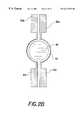
- FIG. 2Ashows a cross section of a nozzle with asymmetric heating deflection.
- FIG. 2Bshows a top view of the nozzle with asymmetric heating deflection.
- FIG. 3is an enlarged cross section view of the nozzle with asymmetric heating deflection.
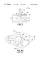
- FIG. 4Ais a top view of a heater according to the prior art.
- FIG. 4Bis a section view of a print head having the heater of FIG. 4 A.
- FIG. 4Cis an operational view of the print head of FIG. 4 C.
- FIGS. 5A-5Care views similar to FIGS. 4A-4C according to the present invention.
- FIG. 6is a view similar to FIG. 5C of an embodiment of a print head having a passivation layer.
- FIGS. 7A-7Care views similar to FIGS. 5A-5C according to another embodiment of the present invention.
- FIGS. 8A and 8Bare views similar to FIGS. 5B and 5C of another embodiment of the present invention.
- FIGS. 9 and 10are views similar to FIG. 5C of an embodiment of a print heads of the embodiments shown in FIGS. 7A-7C and FIGS. 8A and 8B, respectively, having a passivation layer.
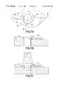
- FIG. 11is a cross section of a nozzle according to another embodiment of the present invention.
- FIG. 12is a cross section of a nozzle according to another embodiment of the present invention.
- FIGS. 13A and 13Bare cross section views of a nozzle according to another embodiment of the present invention.
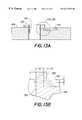
- FIGS. 14A and 14Bare cross section views of a nozzle according to another embodiment of the present invention.
- FIGS. 15A-15Dare views similar to FIGS. 11, 12 , 13 A, 14 A, respectively, including passivation layers.
- a continuous ink jet printer systemincludes an image source 10 such as a scanner or computer which provides raster image data, outline image data in the form of a page description language, or other forms of digital image data.
- This image datais converted to half-toned bitmap image data by an image processing unit 12 which also stores the image data in memory.
- a plurality of heater control circuits 14read data from the image memory and apply time-varying electrical pulses to a set of nozzle heaters 50 that are part of a print head 16 . These pulses are applied at an appropriate time, and to the appropriate nozzle, so that drops formed from a continuous ink jet stream will form spots on a recording medium 18 in the appropriate position designated by the data in the image memory.
- Recording medium 18is moved relative to print head 16 by a recording medium transport system 20 , which is electronically controlled by a recording medium transport control system 22 , and which in turn is controlled by a micro-controller 24 .
- the recording medium transport system shown in FIG. 1is a schematic only, and many different mechanical configurations are possible.
- a transfer rollercould be used as recording medium transport system 20 to facilitate transfer of the ink drops to recording medium 18 .
- Such transfer roller technologyis well known in the art.
- page width print headsit is most convenient to move recording medium 18 past a stationary print head.
- Inkis contained in an ink reservoir 28 under pressure.
- continuous ink jet drop streamsare unable to reach recording medium 18 due to an ink gutter 17 that blocks the stream and which may allow a portion of the ink to be recycled by an ink recycling unit 19 .
- the ink recycling unitreconditions the ink and feeds it back to reservoir 28 .
- Such ink recycling unitsare well known in the art.
- the ink pressure suitable for optimal operationwill depend on a number of factors, including geometry and thermal properties of the nozzles and thermal properties of the ink.
- a constant ink pressurecan be achieved by applying pressure to ink reservoir 28 under the control of ink pressure regulator 26 .
- the inkis distributed to the back surface of print head 16 by an ink channel device 30 .
- the inkpreferably flows through slots and/or holes etched through a silicon substrate of print head 16 to its front surface, where a plurality of nozzles and heaters are situated.
- print head 16fabricated from silicon, it is possible to integrate heater control circuits 14 with the print head.
- FIG. 2Ais a cross-sectional view of one nozzle tip of an array of such tips that form continuous ink jet print head 16 of FIG. 1 according the above-cited co-pending application Ser. No. 08/954,317.
- An ink delivery channel 40along with a plurality of nozzle bores 46 are etched in a substrate 42 , which is silicon in this example. Delivery channel 40 and nozzle bores 46 may be formed by anisotropic wet etching of silicon, using a p + etch stop layer to form the nozzle bores.
- Ink 70 in delivery channel 40is pressurized above atmospheric pressure, and forms a stream 60 .
- stream 60breaks into a plurality of drops 66 due to a periodic heat pulse supplied by a heater 50 .
- the heater of the above-cited co-pending application Ser. No. 08/954,317has two sections, each covering approximately one-half of the nozzle perimeter. Power connections 59 a and 59 b and ground connections 61 a and 61 b from the drive circuitry to heater annulus 50 are also shown.
- Stream 60(FIG. 2A) may be deflected by an asymmetric application of heat by supplying electrical current to one, but not both, of the heater sections.
- drops 66may be blocked from reaching recording medium 18 by a cut-off device such as an ink gutter 17 .
- ink gutter 17may be placed to block undeflected drops 67 so that deflected drops 66 will be allowed to reach recording medium 18 .
- the heaterwas made of polysilicon doped at a level of about thirty ohms/square, although other resistive heater material could be used.
- Heater 50is separated from substrate 42 by thermal and electrical insulating layers 56 to minimize heat loss to the substrate.
- the nozzle boremay be etched allowing the nozzle exit orifice to be defined by insulating layers 56 .
- the layers in contact with the inkcan be passivated with a thin film layer for protection.
- the print head surfacecan be coated with a hydrophobizing layer 68 to prevent accidental spread of the ink across the front of the print head.
- FIG. 3is an enlarged view of the nozzle area of the above-cited co-pending application Ser. No. 08/954,317.
- a meniscus 51is formed where the liquid stream makes contact with the heater edges.
- the contact line that is initially on the outside edge of the heater(illustrated by the dotted line) is moved inwards toward the inside edge of the heater (illustrated by the solid line).
- the other side of the stream(the right-hand side in FIG. 3) stays pinned to the non-activated heater.
- the effect of the inward moving contact lineis to deflect the stream in a direction away from the active heater section (left to right in FIG. 3 or in the +x direction). At some time after the electrical pulse ends the contact line returns toward the outside edge of the heater.
- an electrical heater 100surrounds a central bore 102 on a substrate 104 .
- the boreis an orifice through which ink flows.
- Electrical leads 106 and 108contact the heater so that the heater can be selected operated. As best seen in FIG.
- ink wicking along the heater leadscan distort the shape of the meniscus 110 in the vicinity of the heater and can cause the drops to be ejected at an angle if the wicking is not symmetrical.
- heater leads 106 and 108are contacted by a metal trace 112 (shown in FIG. 4 B), as is well known in the art of semiconductor circuit fabrication. The contact to the trace is removed from vicinity the ink meniscus so that the trace does not contact the meniscus and plays no role in determining the shape of the heater where the heater contacts the meniscus.
- an electrical heater 100is formed as an annulus such as by deposition, lithographic patterning and subsequent etching, or other methods such as described in U.S. Pat. No. 5,812,159.
- Heater 100surrounds a central bore 102 on a substrate 104 .
- the boreis an orifice through which ink flows.
- the inkflows in a continuous stream, although the print head could be drop on demand.
- Electrical leads 106 and 108contact the heater so that the heater can be selected operated.
- a dielectric ring 114is aligned over electrical heater 100 .
- FIG. 5Cillustrates that the meniscus 110 of ink coulomb 116 contacts the upper surface of dielectric ring 114 in an axially symmetric manner.
- the direction of ink column propagationin the illustrated case of continuous ink jet printing, is substantially perpendicular to orifice plate of the print head.
- the ink columnwhich will break into ink drops (not shown), and the ink drops themselves will move substantially perpendicular the orifice plane.
- the direction of drop ejectionis substantially perpendicular to orifice plane.
- dielectric ring 114can serve as a mask during etching heater 100 , and thus the dielectric ring is self-aligned to the heater. Electrical contact to heater leads 106 and 108 is made remotely from the heater by metal trace 112 . The trace plays no role in determining the shape of heater 100 where the heater contacts the ink meniscus.
- FIG. 6illustrates another configuration of the present invention, wherein a thin layer 118 of dielectric passivation material has been deposited over the top and sides of heater 100 such as by chemical vapor deposition, thermal evaporation, e-beam evaporation, sputtering, and spin-on techniques.
- the passivation materialmay be SiOx, Si 3 N 4 , SiC, TeflonTM, Ta 2 O 5 , etc.
- the passivation materialreduces or eliminates deposition of ink constituents on the heater or deterioration of the heater in the presence of ink when a voltage is applied to heat the ring.
- the direction of drop ejection in drop on demand printing or of ink column propagation in continuous ink jet printingremains substantially perpendicular to the orifice plate.
- FIGS. 5A-5C and 6may not be optimal in all instances because of the large dielectric ring 114 material which resides over heater 100 . This dielectric material may reduce thermal contact of the heater with the ink.
- Alternative embodiments, shown in FIGS. 7A-7C, 8 A- 8 B, 9 , and 10provide more direct contact between a heater 120 and the ink in a manner which still avoids the wicking shown in FIG. 4 C.
- heater 120is formed as an annulus which overlays underlying a pair of metal traces 122 and 124 . The heater may be provided so as to be offset with respect to the trace as illustrated in FIGS.
- an ink meniscus 126 contacting the heateris pinned to the outside edge of the heater and is symmetrically disposed around the heater.
- the outside edge of the heateris vertically higher in the regions where it overlies the traces than the portion of the heater in the region where it does not overlie the traces, the angle of the meniscus relative to the direction perpendicular to the orifice plane is very nearly uniform around the perimeter of the meniscus, as is well known to those skilled in the art of solid-fluid contact. Therefore, the difference in height does not cause a significant effect on the direction of drop ejection. This is true for the case in which heater is provided to be offset from the traces (FIG. 7C) or to be self-aligned to the traces (FIG. 8 B).
- the heater geometries described in the previous embodimentsmay be advantageously modified in at least two ways: (i) by offsetting the alignment between the edge of the heater and the edge of the bore and (ii) by incorporation of a dielectric passivation layer surrounding the heater, the trace, and the bore. These augmentations are discussed in relation to FIGS. 9 and 10, wherein an overlying dielectric passivation layers 128 and 130 , respectively, are shown provided over the traces and heater and extending into the bore region. While incorporation of a dielectric passivation layer surrounding the heater alters both the flow of ink in the vicinity of the heater and the temperature of the ink in proximity to the heater, it serves to protect the heater from corrosion or deposition of ink components caused by heater operation.
- the tracesare spaced away from the inner edge of the heater.
- the bore edgeis aligned to the inner edge of the heater.
- the trace and inner edge of the heaterare aligned to the bore edge.
- FIGS. 7A-7C, 8 A- 8 B, 9 , and 10may be further improved by making the surface of the heater entirely planar.
- planarityis achieved by inlaying a pair of traces 132 and 134 into substrate 104 .
- Heater 120is then provided entirely over the inlaid trace and has a planar upper surface.
- the inner edge of the heateris aligned to the edge of bore 102 and to the inner edge of the trace.
- FIG. 12the inner edge of the heater is aligned to the inner edge of bore 102 and the trace is offset from the inner edge of the heater.
- the geometry of FIG. 12better protects the trace from corrosion due to the ink and reduces the conduction of heat to ink in the bore.
- the inside edge of heater 120is offset a distance t 2 away from the inside edge of bore 102
- the outside edge of the heateris offset a distance t 3 from the inside edge of the trace
- the bottom of the heaterextends a distance t 1 below the top of the inlaid trace.
- the inlaid traces with the heaters shown in FIGS. 11, 12 , 13 A, and 14 Amay additionally be protected from the corrosive effects of ink by providing at least one layer of dielectric passivation which extends into the bore.
- a passivation layeris shown in FIG. 15A-15D, respectively, as a deposited layer spaced a distance S 1 from the inner edge of the bore.
- FIGS. 15A-15Dcorrespond to cases where the heater is aligned, offset, or partially inlaid, respectively, in relation to the inlaid trace.
Landscapes
- Particle Formation And Scattering Control In Inkjet Printers (AREA)
Abstract
Description
Claims (9)
Priority Applications (3)
| Application Number | Priority Date | Filing Date | Title |
|---|---|---|---|
| US09/334,810US6217156B1 (en) | 1999-06-17 | 1999-06-17 | Continuous ink jet print head having heater with symmetrical configuration |
| EP00201963AEP1060889B1 (en) | 1999-06-17 | 2000-06-05 | Continuous ink jet print head having heater with symmetrical configuration |
| DE60022577TDE60022577T2 (en) | 1999-06-17 | 2000-06-05 | CONTINUOUSLY WORKING INK JET PRINT HEAD WITH SYMMETRICALLY-MADE HEATING ELEMENT |
Applications Claiming Priority (1)
| Application Number | Priority Date | Filing Date | Title |
|---|---|---|---|
| US09/334,810US6217156B1 (en) | 1999-06-17 | 1999-06-17 | Continuous ink jet print head having heater with symmetrical configuration |
Publications (1)
| Publication Number | Publication Date |
|---|---|
| US6217156B1true US6217156B1 (en) | 2001-04-17 |
Family
ID=23308937
Family Applications (1)
| Application Number | Title | Priority Date | Filing Date |
|---|---|---|---|
| US09/334,810Expired - LifetimeUS6217156B1 (en) | 1999-06-17 | 1999-06-17 | Continuous ink jet print head having heater with symmetrical configuration |
Country Status (3)
| Country | Link |
|---|---|
| US (1) | US6217156B1 (en) |
| EP (1) | EP1060889B1 (en) |
| DE (1) | DE60022577T2 (en) |
Cited By (4)
| Publication number | Priority date | Publication date | Assignee | Title |
|---|---|---|---|---|
| US6554389B1 (en) | 2001-12-17 | 2003-04-29 | Eastman Kodak Company | Inkjet drop selection a non-uniform airstream |
| US6663221B2 (en)* | 2000-12-06 | 2003-12-16 | Eastman Kodak Company | Page wide ink jet printing |
| US20070268336A1 (en)* | 2006-05-19 | 2007-11-22 | International United Technology Co., Ltd. | Inkjet printhead |
| US20080053027A1 (en)* | 1996-06-11 | 2008-03-06 | Moriau Stefan S G | Floor panels with edge connectors |
Families Citing this family (1)
| Publication number | Priority date | Publication date | Assignee | Title |
|---|---|---|---|---|
| US6923529B2 (en) | 2001-12-26 | 2005-08-02 | Eastman Kodak Company | Ink-jet printing with reduced cross-talk |
Citations (2)
| Publication number | Priority date | Publication date | Assignee | Title |
|---|---|---|---|---|
| US5812159A (en)* | 1996-07-22 | 1998-09-22 | Eastman Kodak Company | Ink printing apparatus with improved heater |
| US5880759A (en)* | 1995-04-12 | 1999-03-09 | Eastman Kodak Company | Liquid ink printing apparatus and system |
Family Cites Families (6)
| Publication number | Priority date | Publication date | Assignee | Title |
|---|---|---|---|---|
| US1941001A (en) | 1929-01-19 | 1933-12-26 | Rca Corp | Recorder |
| US3878519A (en) | 1974-01-31 | 1975-04-15 | Ibm | Method and apparatus for synchronizing droplet formation in a liquid stream |
| CA1127227A (en) | 1977-10-03 | 1982-07-06 | Ichiro Endo | Liquid jet recording process and apparatus therefor |
| US4490728A (en) | 1981-08-14 | 1984-12-25 | Hewlett-Packard Company | Thermal ink jet printer |
| US5896155A (en)* | 1997-02-28 | 1999-04-20 | Eastman Kodak Company | Ink transfer printing apparatus with drop volume adjustment |
| US6079821A (en)* | 1997-10-17 | 2000-06-27 | Eastman Kodak Company | Continuous ink jet printer with asymmetric heating drop deflection |
- 1999
- 1999-06-17USUS09/334,810patent/US6217156B1/ennot_activeExpired - Lifetime
- 2000
- 2000-06-05EPEP00201963Apatent/EP1060889B1/ennot_activeExpired - Lifetime
- 2000-06-05DEDE60022577Tpatent/DE60022577T2/ennot_activeExpired - Lifetime
Patent Citations (2)
| Publication number | Priority date | Publication date | Assignee | Title |
|---|---|---|---|---|
| US5880759A (en)* | 1995-04-12 | 1999-03-09 | Eastman Kodak Company | Liquid ink printing apparatus and system |
| US5812159A (en)* | 1996-07-22 | 1998-09-22 | Eastman Kodak Company | Ink printing apparatus with improved heater |
Cited By (5)
| Publication number | Priority date | Publication date | Assignee | Title |
|---|---|---|---|---|
| US20080053027A1 (en)* | 1996-06-11 | 2008-03-06 | Moriau Stefan S G | Floor panels with edge connectors |
| US6663221B2 (en)* | 2000-12-06 | 2003-12-16 | Eastman Kodak Company | Page wide ink jet printing |
| US6554389B1 (en) | 2001-12-17 | 2003-04-29 | Eastman Kodak Company | Inkjet drop selection a non-uniform airstream |
| US20070268336A1 (en)* | 2006-05-19 | 2007-11-22 | International United Technology Co., Ltd. | Inkjet printhead |
| US7740341B2 (en) | 2006-05-19 | 2010-06-22 | International United Technology Co., Ltd. | Inkjet printhead |
Also Published As
| Publication number | Publication date |
|---|---|
| EP1060889A3 (en) | 2001-02-28 |
| EP1060889B1 (en) | 2005-09-14 |
| DE60022577T2 (en) | 2006-06-22 |
| EP1060889A2 (en) | 2000-12-20 |
| DE60022577D1 (en) | 2005-10-20 |
Similar Documents
| Publication | Publication Date | Title |
|---|---|---|
| US6217163B1 (en) | Continuous ink jet print head having multi-segment heaters | |
| US6079821A (en) | Continuous ink jet printer with asymmetric heating drop deflection | |
| US6509917B1 (en) | Continuous ink jet printer with binary electrostatic deflection | |
| US6746108B1 (en) | Method and apparatus for printing ink droplets that strike print media substantially perpendicularly | |
| EP1112848B1 (en) | Continuous ink jet printer with micro-valve deflection mechanism and method of making same | |
| EP1108542B1 (en) | Continuous ink jet system having non-circular orifices | |
| EP1016526B1 (en) | Continuous ink jet print head having power-adjustable segmented heaters | |
| US6012805A (en) | Continuous ink jet printer with variable contact drop deflection | |
| JP2002210981A (en) | Ink jet unit having amplified asymmetrically heated droplet deflection | |
| US6588890B1 (en) | Continuous inkjet printer with heat actuated microvalves for controlling the direction of delivered ink | |
| US6520629B1 (en) | Steering fluid device and method for increasing the angle of deflection of ink droplets generated by an asymmetric heat-type inkjet printer | |
| EP1112847B1 (en) | Continuous ink jet printer with a notch deflector | |
| US6158845A (en) | Ink jet print head having heater upper surface coplanar with a surrounding surface of substrate | |
| US6217156B1 (en) | Continuous ink jet print head having heater with symmetrical configuration | |
| JP2001315329A (en) | Continuous ink jet printer deflecting liquid drop through asymmetric heating | |
| EP0911166A2 (en) | Continuous ink jet printer with electrostatic drop deflection | |
| US6578955B2 (en) | Continuous inkjet printer with actuatable valves for controlling the direction of delivered ink | |
| US6402305B1 (en) | Method for preventing ink drop misdirection in an asymmetric heat-type ink jet printer | |
| US6412910B1 (en) | Permanent alteration of a printhead for correction of mis-direction of emitted ink drops | |
| US7461927B2 (en) | Drop deflection selectable via jet steering | |
| US10207505B1 (en) | Method for fabricating a charging device |
Legal Events
| Date | Code | Title | Description |
|---|---|---|---|
| AS | Assignment | Owner name:EASTMAN KODAK COMPANY, NEW YORK Free format text:ASSIGNMENT OF ASSIGNORS INTEREST;ASSIGNORS:HAWKINS, GILBERT A.;CHWALEK, JAMES M.;ANAGNOSTOPOULOS, CONSTANTINE N.;REEL/FRAME:010047/0644 Effective date:19990614 | |
| STCF | Information on status: patent grant | Free format text:PATENTED CASE | |
| FEPP | Fee payment procedure | Free format text:PAYOR NUMBER ASSIGNED (ORIGINAL EVENT CODE: ASPN); ENTITY STATUS OF PATENT OWNER: LARGE ENTITY | |
| FPAY | Fee payment | Year of fee payment:4 | |
| FPAY | Fee payment | Year of fee payment:8 | |
| AS | Assignment | Owner name:CITICORP NORTH AMERICA, INC., AS AGENT, NEW YORK Free format text:SECURITY INTEREST;ASSIGNORS:EASTMAN KODAK COMPANY;PAKON, INC.;REEL/FRAME:028201/0420 Effective date:20120215 | |
| FPAY | Fee payment | Year of fee payment:12 | |
| AS | Assignment | Owner name:WILMINGTON TRUST, NATIONAL ASSOCIATION, AS AGENT, MINNESOTA Free format text:PATENT SECURITY AGREEMENT;ASSIGNORS:EASTMAN KODAK COMPANY;PAKON, INC.;REEL/FRAME:030122/0235 Effective date:20130322 Owner name:WILMINGTON TRUST, NATIONAL ASSOCIATION, AS AGENT, Free format text:PATENT SECURITY AGREEMENT;ASSIGNORS:EASTMAN KODAK COMPANY;PAKON, INC.;REEL/FRAME:030122/0235 Effective date:20130322 | |
| AS | Assignment | Owner name:BANK OF AMERICA N.A., AS AGENT, MASSACHUSETTS Free format text:INTELLECTUAL PROPERTY SECURITY AGREEMENT (ABL);ASSIGNORS:EASTMAN KODAK COMPANY;FAR EAST DEVELOPMENT LTD.;FPC INC.;AND OTHERS;REEL/FRAME:031162/0117 Effective date:20130903 Owner name:JPMORGAN CHASE BANK, N.A., AS ADMINISTRATIVE, DELAWARE Free format text:INTELLECTUAL PROPERTY SECURITY AGREEMENT (FIRST LIEN);ASSIGNORS:EASTMAN KODAK COMPANY;FAR EAST DEVELOPMENT LTD.;FPC INC.;AND OTHERS;REEL/FRAME:031158/0001 Effective date:20130903 Owner name:BARCLAYS BANK PLC, AS ADMINISTRATIVE AGENT, NEW YORK Free format text:INTELLECTUAL PROPERTY SECURITY AGREEMENT (SECOND LIEN);ASSIGNORS:EASTMAN KODAK COMPANY;FAR EAST DEVELOPMENT LTD.;FPC INC.;AND OTHERS;REEL/FRAME:031159/0001 Effective date:20130903 Owner name:BARCLAYS BANK PLC, AS ADMINISTRATIVE AGENT, NEW YO Free format text:INTELLECTUAL PROPERTY SECURITY AGREEMENT (SECOND LIEN);ASSIGNORS:EASTMAN KODAK COMPANY;FAR EAST DEVELOPMENT LTD.;FPC INC.;AND OTHERS;REEL/FRAME:031159/0001 Effective date:20130903 Owner name:PAKON, INC., NEW YORK Free format text:RELEASE OF SECURITY INTEREST IN PATENTS;ASSIGNORS:CITICORP NORTH AMERICA, INC., AS SENIOR DIP AGENT;WILMINGTON TRUST, NATIONAL ASSOCIATION, AS JUNIOR DIP AGENT;REEL/FRAME:031157/0451 Effective date:20130903 Owner name:JPMORGAN CHASE BANK, N.A., AS ADMINISTRATIVE, DELA Free format text:INTELLECTUAL PROPERTY SECURITY AGREEMENT (FIRST LIEN);ASSIGNORS:EASTMAN KODAK COMPANY;FAR EAST DEVELOPMENT LTD.;FPC INC.;AND OTHERS;REEL/FRAME:031158/0001 Effective date:20130903 Owner name:EASTMAN KODAK COMPANY, NEW YORK Free format text:RELEASE OF SECURITY INTEREST IN PATENTS;ASSIGNORS:CITICORP NORTH AMERICA, INC., AS SENIOR DIP AGENT;WILMINGTON TRUST, NATIONAL ASSOCIATION, AS JUNIOR DIP AGENT;REEL/FRAME:031157/0451 Effective date:20130903 | |
| AS | Assignment | Owner name:FAR EAST DEVELOPMENT LTD., NEW YORK Free format text:RELEASE BY SECURED PARTY;ASSIGNOR:JP MORGAN CHASE BANK, N.A., AS ADMINISTRATIVE AGENT;REEL/FRAME:049814/0001 Effective date:20190617 Owner name:LASER PACIFIC MEDIA CORPORATION, NEW YORK Free format text:RELEASE BY SECURED PARTY;ASSIGNOR:JP MORGAN CHASE BANK, N.A., AS ADMINISTRATIVE AGENT;REEL/FRAME:049814/0001 Effective date:20190617 Owner name:QUALEX, INC., NEW YORK Free format text:RELEASE BY SECURED PARTY;ASSIGNOR:JP MORGAN CHASE BANK, N.A., AS ADMINISTRATIVE AGENT;REEL/FRAME:049814/0001 Effective date:20190617 Owner name:PAKON, INC., NEW YORK Free format text:RELEASE BY SECURED PARTY;ASSIGNOR:JP MORGAN CHASE BANK, N.A., AS ADMINISTRATIVE AGENT;REEL/FRAME:049814/0001 Effective date:20190617 Owner name:CREO MANUFACTURING AMERICA LLC, NEW YORK Free format text:RELEASE BY SECURED PARTY;ASSIGNOR:JP MORGAN CHASE BANK, N.A., AS ADMINISTRATIVE AGENT;REEL/FRAME:049814/0001 Effective date:20190617 Owner name:KODAK AMERICAS, LTD., NEW YORK Free format text:RELEASE BY SECURED PARTY;ASSIGNOR:JP MORGAN CHASE BANK, N.A., AS ADMINISTRATIVE AGENT;REEL/FRAME:049814/0001 Effective date:20190617 Owner name:KODAK IMAGING NETWORK, INC., NEW YORK Free format text:RELEASE BY SECURED PARTY;ASSIGNOR:JP MORGAN CHASE BANK, N.A., AS ADMINISTRATIVE AGENT;REEL/FRAME:049814/0001 Effective date:20190617 Owner name:KODAK AVIATION LEASING LLC, NEW YORK Free format text:RELEASE BY SECURED PARTY;ASSIGNOR:JP MORGAN CHASE BANK, N.A., AS ADMINISTRATIVE AGENT;REEL/FRAME:049814/0001 Effective date:20190617 Owner name:EASTMAN KODAK COMPANY, NEW YORK Free format text:RELEASE BY SECURED PARTY;ASSIGNOR:JP MORGAN CHASE BANK, N.A., AS ADMINISTRATIVE AGENT;REEL/FRAME:049814/0001 Effective date:20190617 Owner name:FPC, INC., NEW YORK Free format text:RELEASE BY SECURED PARTY;ASSIGNOR:JP MORGAN CHASE BANK, N.A., AS ADMINISTRATIVE AGENT;REEL/FRAME:049814/0001 Effective date:20190617 Owner name:KODAK (NEAR EAST), INC., NEW YORK Free format text:RELEASE BY SECURED PARTY;ASSIGNOR:JP MORGAN CHASE BANK, N.A., AS ADMINISTRATIVE AGENT;REEL/FRAME:049814/0001 Effective date:20190617 Owner name:KODAK REALTY, INC., NEW YORK Free format text:RELEASE BY SECURED PARTY;ASSIGNOR:JP MORGAN CHASE BANK, N.A., AS ADMINISTRATIVE AGENT;REEL/FRAME:049814/0001 Effective date:20190617 Owner name:NPEC, INC., NEW YORK Free format text:RELEASE BY SECURED PARTY;ASSIGNOR:JP MORGAN CHASE BANK, N.A., AS ADMINISTRATIVE AGENT;REEL/FRAME:049814/0001 Effective date:20190617 Owner name:KODAK PORTUGUESA LIMITED, NEW YORK Free format text:RELEASE BY SECURED PARTY;ASSIGNOR:JP MORGAN CHASE BANK, N.A., AS ADMINISTRATIVE AGENT;REEL/FRAME:049814/0001 Effective date:20190617 Owner name:KODAK PHILIPPINES, LTD., NEW YORK Free format text:RELEASE BY SECURED PARTY;ASSIGNOR:JP MORGAN CHASE BANK, N.A., AS ADMINISTRATIVE AGENT;REEL/FRAME:049814/0001 Effective date:20190617 | |
| AS | Assignment | Owner name:QUALEX INC., NEW YORK Free format text:RELEASE BY SECURED PARTY;ASSIGNOR:BARCLAYS BANK PLC;REEL/FRAME:052773/0001 Effective date:20170202 Owner name:KODAK (NEAR EAST) INC., NEW YORK Free format text:RELEASE BY SECURED PARTY;ASSIGNOR:BARCLAYS BANK PLC;REEL/FRAME:052773/0001 Effective date:20170202 Owner name:NPEC INC., NEW YORK Free format text:RELEASE BY SECURED PARTY;ASSIGNOR:BARCLAYS BANK PLC;REEL/FRAME:052773/0001 Effective date:20170202 Owner name:KODAK REALTY INC., NEW YORK Free format text:RELEASE BY SECURED PARTY;ASSIGNOR:BARCLAYS BANK PLC;REEL/FRAME:052773/0001 Effective date:20170202 Owner name:FAR EAST DEVELOPMENT LTD., NEW YORK Free format text:RELEASE BY SECURED PARTY;ASSIGNOR:BARCLAYS BANK PLC;REEL/FRAME:052773/0001 Effective date:20170202 Owner name:FPC INC., NEW YORK Free format text:RELEASE BY SECURED PARTY;ASSIGNOR:BARCLAYS BANK PLC;REEL/FRAME:052773/0001 Effective date:20170202 Owner name:KODAK AMERICAS LTD., NEW YORK Free format text:RELEASE BY SECURED PARTY;ASSIGNOR:BARCLAYS BANK PLC;REEL/FRAME:052773/0001 Effective date:20170202 Owner name:KODAK PHILIPPINES LTD., NEW YORK Free format text:RELEASE BY SECURED PARTY;ASSIGNOR:BARCLAYS BANK PLC;REEL/FRAME:052773/0001 Effective date:20170202 Owner name:LASER PACIFIC MEDIA CORPORATION, NEW YORK Free format text:RELEASE BY SECURED PARTY;ASSIGNOR:BARCLAYS BANK PLC;REEL/FRAME:052773/0001 Effective date:20170202 Owner name:EASTMAN KODAK COMPANY, NEW YORK Free format text:RELEASE BY SECURED PARTY;ASSIGNOR:BARCLAYS BANK PLC;REEL/FRAME:052773/0001 Effective date:20170202 |