US6216732B1 - Portable fluid transfer conduit - Google Patents
Portable fluid transfer conduitDownload PDFInfo
- Publication number
- US6216732B1 US6216732B1US09/435,375US43537599AUS6216732B1US 6216732 B1US6216732 B1US 6216732B1US 43537599 AUS43537599 AUS 43537599AUS 6216732 B1US6216732 B1US 6216732B1
- Authority
- US
- United States
- Prior art keywords
- conduit
- pump
- fluid transfer
- transfer conduit
- portable
- Prior art date
- Legal status (The legal status is an assumption and is not a legal conclusion. Google has not performed a legal analysis and makes no representation as to the accuracy of the status listed.)
- Expired - Lifetime
Links
- 239000012530fluidSubstances0.000titleclaimsabstractdescription72
- 230000008878couplingEffects0.000claimsabstractdescription26
- 238000010168coupling processMethods0.000claimsabstractdescription26
- 238000005859coupling reactionMethods0.000claimsabstractdescription26
- 239000002699waste materialSubstances0.000claimsdescription4
- 230000004913activationEffects0.000claimsdescription3
- 230000003213activating effectEffects0.000claimsdescription2
- 230000000153supplemental effectEffects0.000claims8
- 239000012190activatorSubstances0.000abstractdescription2
- 239000003921oilSubstances0.000description16
- 239000004020conductorSubstances0.000description3
- 230000005484gravityEffects0.000description3
- 239000000463materialSubstances0.000description3
- 238000005086pumpingMethods0.000description3
- 239000004698PolyethyleneSubstances0.000description2
- PPBRXRYQALVLMV-UHFFFAOYSA-NStyreneChemical compoundC=CC1=CC=CC=C1PPBRXRYQALVLMV-UHFFFAOYSA-N0.000description2
- -1polyethylenePolymers0.000description2
- 229920000573polyethylenePolymers0.000description2
- 238000010926purgeMethods0.000description2
- 239000010935stainless steelSubstances0.000description2
- 229910001220stainless steelInorganic materials0.000description2
- 229920000297RayonPolymers0.000description1
- 238000009954braidingMethods0.000description1
- 238000002485combustion reactionMethods0.000description1
- 229920001971elastomerPolymers0.000description1
- 239000010720hydraulic oilSubstances0.000description1
- 230000000977initiatory effectEffects0.000description1
- 239000010705motor oilSubstances0.000description1
- 229920003052natural elastomerPolymers0.000description1
- 229920001194natural rubberPolymers0.000description1
- 239000005060rubberSubstances0.000description1
- 238000005070samplingMethods0.000description1
- 229920003051synthetic elastomerPolymers0.000description1
- 239000005061synthetic rubberSubstances0.000description1
Images


Classifications
- F—MECHANICAL ENGINEERING; LIGHTING; HEATING; WEAPONS; BLASTING
- F01—MACHINES OR ENGINES IN GENERAL; ENGINE PLANTS IN GENERAL; STEAM ENGINES
- F01M—LUBRICATING OF MACHINES OR ENGINES IN GENERAL; LUBRICATING INTERNAL COMBUSTION ENGINES; CRANKCASE VENTILATING
- F01M11/00—Component parts, details or accessories, not provided for in, or of interest apart from, groups F01M1/00 - F01M9/00
- F01M11/04—Filling or draining lubricant of or from machines or engines
- F01M11/0408—Sump drainage devices, e.g. valves, plugs
- Y—GENERAL TAGGING OF NEW TECHNOLOGICAL DEVELOPMENTS; GENERAL TAGGING OF CROSS-SECTIONAL TECHNOLOGIES SPANNING OVER SEVERAL SECTIONS OF THE IPC; TECHNICAL SUBJECTS COVERED BY FORMER USPC CROSS-REFERENCE ART COLLECTIONS [XRACs] AND DIGESTS
- Y10—TECHNICAL SUBJECTS COVERED BY FORMER USPC
- Y10T—TECHNICAL SUBJECTS COVERED BY FORMER US CLASSIFICATION
- Y10T137/00—Fluid handling
- Y10T137/6851—With casing, support, protector or static constructional installations
- Y10T137/6855—Vehicle
- Y10T137/6881—Automotive
- Y—GENERAL TAGGING OF NEW TECHNOLOGICAL DEVELOPMENTS; GENERAL TAGGING OF CROSS-SECTIONAL TECHNOLOGIES SPANNING OVER SEVERAL SECTIONS OF THE IPC; TECHNICAL SUBJECTS COVERED BY FORMER USPC CROSS-REFERENCE ART COLLECTIONS [XRACs] AND DIGESTS
- Y10—TECHNICAL SUBJECTS COVERED BY FORMER USPC
- Y10T—TECHNICAL SUBJECTS COVERED BY FORMER US CLASSIFICATION
- Y10T137/00—Fluid handling
- Y10T137/8376—Combined
- Y—GENERAL TAGGING OF NEW TECHNOLOGICAL DEVELOPMENTS; GENERAL TAGGING OF CROSS-SECTIONAL TECHNOLOGIES SPANNING OVER SEVERAL SECTIONS OF THE IPC; TECHNICAL SUBJECTS COVERED BY FORMER USPC CROSS-REFERENCE ART COLLECTIONS [XRACs] AND DIGESTS
- Y10—TECHNICAL SUBJECTS COVERED BY FORMER USPC
- Y10T—TECHNICAL SUBJECTS COVERED BY FORMER US CLASSIFICATION
- Y10T137/00—Fluid handling
- Y10T137/8593—Systems
- Y10T137/85978—With pump
- Y10T137/86099—Hand pump
Definitions
- the present inventionrelates to fluid transfer conduit having flow control means and an adapter means for connection with a source of fluid, and, in particular, to a portable fluid transfer conduit that is useful in the removal of fluids from equipment which do not have conveniently located outlet ports.
- fluid circulation pumpsare provided which are external to the machine or engine.
- some of the newer equipmentis fitted with external prelubrication devices which permit oil or fluid to commence circulation prior to the activation of the primary equipment or engine on which it is fitted.
- Illustrative of such devicesis the prelubrication device shown in U.S. Pat. No. 4,502,431 which is incorporated herein by reference, which is typically fitted to a diesel engine used in power equipment, trucks or heavy equipment.
- circulation devices used to heat hydraulic fluidare applicable to the present invention.
- an object of the inventionto provide portable fluid transfer conduit that will facilitate the removal of fluids remote from the discharge port. It is also an object of the present invention to provide a conduit for use in fluid transfer that is adapted to fit to a discharge port and remotely control the flow of fluid from an engine or equipment. Another object of the invention is to provide a portable transfer conduit that includes fluid pump means for extracting fluid from a machine or engine. A further object of the invention is adapter means for connecting the fluid transfer conduit to an outlet port for such fluid. Another object of the invention is an adapter connector for coupling an air evacuation means to purge or remove part of the fluid from the channels of the machine and filter.
- the present inventioncomprises a portable fluid transfer conduit having at least one flexible fluid conduit.
- the conduitis made from a rubber or polymeric material, stainless steel braiding or the like. In most typical applications it comprises a polyethylene or propropylene tubing.
- the conduitincludes an inlet port and an outlet port.
- the inlet portis adapted for connection with the discharge port of a fluid source such as the sump of an engine or a prelubrication pump.
- a coupler meansis provided at the inlet port to couple the conduit with discharge port of the fluid source.
- a quick connect-disconnect fittingis secured to the inlet port of the conduit and a mateable fitting therewith at the discharge port.
- a flow control meansis positioned adjacent the outlet port of the conduit for controlling the flow of fluid from said source, such as a engine sump, through the conduit.
- the flow control meansincludes an actuator electrically connected to means for pumping the fluid from said fluid source, such as a prelubrication pump used in a diesel or internal combustion engine.
- the flow control actuatorincludes disconnectable electrical connection means for control of the pump means.
- the flow control meanscomprises a pump for pumping the fluid from the fluid source through the conduit.
- the actuatorincludes electrical means such as a battery pack or connections to an external source of power such as an electrical wall outlet or battery on vehicle or equipment.
- the electrical connectionis similar to the first embodiment in which disconnectable electric connectors are used.
- the preferred pumpis a light weight dc-motor driven pump in which a small light weight rechargeable battery pack is mounted as part of the flow control means.
- a quick connect conduit having a female couplingis used to connect an air gun or supply source of air pressure.
- the conduitincludes a fitting in the line between the prelubrication pump and the system filter. This is preferably used prior to the removal of oil from the system to clear oil channels and at least some of the oil from the filter to simplify oil removal and make it safer for the workers.
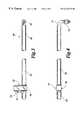
- FIG. 1is a side elevation of a presently preferred embodiment of the invention
- FIG. 2is a plan view of the embodiment shown in FIG. 1 showing a quick connect coupling
- FIG. 3is a plan view of another embodiment of the invention having a pump integrally included in the flow control means;
- FIG. 4is a side elevation of the embodiment shown in FIG. 3;
- FIGS. 5 and 6are two views of a quick connect coupling for use with the present invention.
- FIG. 7is diagrammatic view of a conduit, a quick connect coupling for oil purges.
- the present inventioncomprise a portable fluid transfer conduit 10 having an inlet port 11 and outlet port 12 . Flexibly extending between inlet and outlet ports 11 and 12 is flexible tubing 13 .
- Tubing 13is preferably made from a natural or synthetic rubber material, braided stainless steel or polymeric extruded material such as polyethylene or styrene.
- coupling 14is the male mateable end of a quick disconnect coupling more clearly shown in FIGS. 5 and 6.
- coupling 14can be any type of fitting such as a screw in or a bayonet type coupling.
- a quick connect fittingis adapted to the outlet of the fluid source.
- a bypass or connector meansis easily inserted on the pressure side of the pump to divert the oil from the engine to the fluid transfer conduit 10 . An example is disclosed relative to FIGS. 5 and 6 below.
- flow control means 16Positioned adjacent outlet port 12 is flow control means 16 .
- Flow control meanscomprises in one embodiment an electric or mechanical valve for controlling the flow of fluid through the conduit activated by switch 17 .
- This embodimentis useful where the fluid source does not incorporate a pump means and/or the fluid is gravity transferred.
- flow control means 16is preferably a pass through conduit having switch 17 sealably mounted thereon.
- Switch 17is electrically connected by conductor 18 to electrical connector 19 which is adapted to connect with the pump circuit to activate the pump and control the flow of fluid.
- conductor 18 and connector 19are typically connected to a source of electrical power such as a battery terminal, a magnetic switch, relay contacts or other electromechanical means for activating the pumping means.
- fluid transfer conduit 20comprises a conduit 23 having an inlet port 21 and an outlet port 22 .
- Inlet port 21includes a coupling 24 , preferably a mateable quick connect coupling as shown in FIGS. 5 and 6.
- flow control means 16comprises a small suction, diaphragm, piston or reciprocating pump 28 preferably including a battery pack within.
- Flow control means 16includes activator switch 27 preferably in the form of a “trigger switch” having guard 29 and grip means 31 to facilitate holding the discharge end of fluid transfer conduit 20 . It should be noted, however, that where a long transfer conduit is contemplated, for example 20 to 30 feet in length, it is desirable to locate the pump adjacent or in close proximity to coupling means 14 .
- a power cablesuch as conductor 18 and connector 19 can be used in this embodiment as well.
- the electrical power requiredcan be supplied by a vehicle storage battery or an a-c pump can be connected to an a-c outlet.
- the smaller pump meansare especially useful in the consumer market and the larger pumps are specially applicable to the industrial market.
- Coupling means 14 and 41are adaptable to both fluid transfer conduit embodiments shown with respect to FIGS. 1 and 3.
- Coupling 41connects to the engine oil port (not shown) whereas coupling 14 is attached to conduit 10 .
- Such couplingsare well known in the art and comprise a male quick connector fitting 30 and a female mateable quick connector fitting 32 .
- an electrical receptor 33for receiving electrical connector 19 . It is also possible to include a sensing means on the coupling to indicate that the sump is dry and signal for shut down of the pump.
- a cap 34is shown for protecting receptor 33 between periods of use. As shown in FIGS.
- receptor 33 and fitting 32are mounted on a bracket 36 which is then connected to a source of fluid 37 , such as a prelubrication pump, not otherwise shown.
- a source of fluid 37such as a prelubrication pump, not otherwise shown.
- fitting 32is connected in the output or high pressure side of the fluid source system.
- fitting 32is interposed in the high pressure pump discharge line between pump and an engine.
- a sampling port 39can used to sample oil in a prelubrication system where the prelubrication pumps flows in to 37 . This has the advantage of providing a live sample of oil without requiring the engine to be running.
- an additional fitting 40 attached to air supply 42is mounted on bracket 36 .
- fitting 40is quick connect female fitting adapted to couple to air supply (not shown).
Landscapes
- Engineering & Computer Science (AREA)
- Mechanical Engineering (AREA)
- General Engineering & Computer Science (AREA)
- Loading And Unloading Of Fuel Tanks Or Ships (AREA)
Abstract
Description
Claims (10)
Priority Applications (8)
| Application Number | Priority Date | Filing Date | Title |
|---|---|---|---|
| US09/435,375US6216732B1 (en) | 1997-10-30 | 1999-11-05 | Portable fluid transfer conduit |
| US09/772,604US6708710B1 (en) | 1997-10-30 | 2001-01-30 | Vehicle fluid change apparatus and method |
| US09/836,610US6561219B1 (en) | 1997-10-30 | 2001-04-16 | Portable fluid transfer conduit |
| US10/347,958US6988506B1 (en) | 1997-10-30 | 2003-01-21 | Fluid transfer system |
| US10/414,360US6941969B2 (en) | 1997-10-30 | 2003-04-15 | Vehicle fluid change apparatus |
| US10/612,205US7150286B2 (en) | 1997-10-30 | 2003-07-02 | Methods and systems for performing, monitoring and analyzing multiple machine fluid processes |
| US10/820,551US9062575B2 (en) | 1997-10-30 | 2004-04-08 | Methods and systems for performing, monitoring and analyzing multiple machine fluid processes |
| US11/594,325US7793681B2 (en) | 1997-10-30 | 2006-11-08 | Methods and systems for performing, monitoring and analyzing multiple machine fluid processes |
Applications Claiming Priority (2)
| Application Number | Priority Date | Filing Date | Title |
|---|---|---|---|
| US96133997A | 1997-10-30 | 1997-10-30 | |
| US09/435,375US6216732B1 (en) | 1997-10-30 | 1999-11-05 | Portable fluid transfer conduit |
Related Parent Applications (1)
| Application Number | Title | Priority Date | Filing Date |
|---|---|---|---|
| US96133997AContinuation-In-Part | 1997-10-30 | 1997-10-30 |
Related Child Applications (2)
| Application Number | Title | Priority Date | Filing Date |
|---|---|---|---|
| US09/772,604Continuation-In-PartUS6708710B1 (en) | 1997-10-30 | 2001-01-30 | Vehicle fluid change apparatus and method |
| US09/836,610ContinuationUS6561219B1 (en) | 1997-10-30 | 2001-04-16 | Portable fluid transfer conduit |
Publications (1)
| Publication Number | Publication Date |
|---|---|
| US6216732B1true US6216732B1 (en) | 2001-04-17 |
Family
ID=27030536
Family Applications (2)
| Application Number | Title | Priority Date | Filing Date |
|---|---|---|---|
| US09/435,375Expired - LifetimeUS6216732B1 (en) | 1997-10-30 | 1999-11-05 | Portable fluid transfer conduit |
| US09/836,610Expired - LifetimeUS6561219B1 (en) | 1997-10-30 | 2001-04-16 | Portable fluid transfer conduit |
Family Applications After (1)
| Application Number | Title | Priority Date | Filing Date |
|---|---|---|---|
| US09/836,610Expired - LifetimeUS6561219B1 (en) | 1997-10-30 | 2001-04-16 | Portable fluid transfer conduit |
Country Status (1)
| Country | Link |
|---|---|
| US (2) | US6216732B1 (en) |
Cited By (8)
| Publication number | Priority date | Publication date | Assignee | Title |
|---|---|---|---|---|
| US6325594B1 (en)* | 2000-03-17 | 2001-12-04 | Thomas Pump & Machinery, Inc. | Sealed drain for rotating case pumps |
| US20040045609A1 (en)* | 1997-10-30 | 2004-03-11 | John Apostolides | Vehicle fluid change apparatus |
| US20040059542A1 (en)* | 2002-09-24 | 2004-03-25 | Apostolides John K. | Methods and systems for collecting and processing data in association with machine operation and maintenance |
| US20040211470A1 (en)* | 1997-10-30 | 2004-10-28 | Apostolides John K. | Methods and systems for performing, monitoring and analyzing multiple machine fluid processes |
| US20050173004A1 (en)* | 1997-10-30 | 2005-08-11 | Apostolides John K. | Methods and systems for performing, monitoring and analyzing multiple machine fluid processes |
| US6988506B1 (en) | 1997-10-30 | 2006-01-24 | Rpm Industries, Inc. | Fluid transfer system |
| US20080203726A1 (en)* | 2005-07-28 | 2008-08-28 | Breeser David L | Data Communication System Embedded In A Fluid Dispensing Line With Limited Travel Swivel |
| US20140290761A1 (en)* | 2013-03-15 | 2014-10-02 | RPM Industries, LLC | Valve assembly for machine fluid operations |
Families Citing this family (8)
| Publication number | Priority date | Publication date | Assignee | Title |
|---|---|---|---|---|
| BR0102116B1 (en) | 2000-05-10 | 2010-09-21 | component for a breathing circuit member. | |
| US7559324B2 (en) | 2000-06-21 | 2009-07-14 | Fisher & Paykel Healthcare Limited | Conduit with heated wick |
| AU2003244171B2 (en) | 2002-09-09 | 2007-11-15 | Fisher & Paykel Healthcare Limited | Limb for Breathing Circuit |
| US7493902B2 (en) | 2003-05-30 | 2009-02-24 | Fisher & Paykel Healthcare Limited | Breathing assistance apparatus |
| AU2004203870B2 (en) | 2003-09-17 | 2011-03-03 | Fisher & Paykel Healthcare Limited | Breathable Respiratory Mask |
| US7422021B2 (en)* | 2005-09-16 | 2008-09-09 | Dwight Leaphart | Method of cleaning oil strainer |
| US10532177B2 (en) | 2009-12-22 | 2020-01-14 | Fisher & Paykel Healthcare Limited | Components for medical circuits |
| CN109475714B (en) | 2016-06-07 | 2022-09-02 | 菲舍尔和佩克尔保健有限公司 | Breathing circuit component for breathing apparatus |
Citations (27)
| Publication number | Priority date | Publication date | Assignee | Title |
|---|---|---|---|---|
| US3583527A (en) | 1969-07-16 | 1971-06-08 | Theodore T Raichel | Prestart oil-pressurizing device |
| US3583525A (en) | 1968-12-30 | 1971-06-08 | Clifton R Holcomb | Engine preoiler |
| US3722623A (en) | 1971-05-25 | 1973-03-27 | Ram Enterprises Inc | Preliminary lubrication device |
| US3802564A (en) | 1972-06-09 | 1974-04-09 | W Turman | Oil filter and adapter |
| US3917207A (en) | 1974-08-19 | 1975-11-04 | Earle W Quigley | Tissue box holder |
| US4014794A (en) | 1974-03-11 | 1977-03-29 | E. I. Du Pont De Nemours And Company | Oil filter adapter |
| US4061204A (en) | 1976-02-09 | 1977-12-06 | Kautz Walter C Jr | Engine pre-oiler |
| US4094293A (en) | 1976-04-16 | 1978-06-13 | Evans John W | Engine preoiler and lubricant reservoir |
| US4112910A (en) | 1976-04-23 | 1978-09-12 | Prelube Corporation | Pre-lube device |
| US4157744A (en) | 1977-07-18 | 1979-06-12 | Capriotti Lawrence J | Lubricating and cooling engine system component |
| US4199950A (en) | 1977-12-01 | 1980-04-29 | Hakason Alton L | Prelubricating and lubricating systems for engines |
| US4402287A (en) | 1982-02-16 | 1983-09-06 | Frantz Filters, Inc. | Oil filter adapter |
| US4502451A (en) | 1982-08-25 | 1985-03-05 | Standard-Thomson Corporation | Diesel fuel control apparatus and system |
| US4502431A (en)* | 1983-03-03 | 1985-03-05 | Lulich John F | Pre-combustion engine lubrication system |
| US4875551A (en) | 1987-10-13 | 1989-10-24 | R. P. M. Industries | Pre-lubricant oil pressure adapter |
| US4977978A (en)* | 1989-07-31 | 1990-12-18 | Batrice Mazen P | Automotive oil change apparatus |
| US5056621A (en)* | 1989-11-09 | 1991-10-15 | Trevino Arnold G | Fluid transfer apparatus and method |
| US5236064A (en) | 1991-09-20 | 1993-08-17 | Wagoner Johnny M | Lubricant charging device |
| US5257678A (en)* | 1992-11-27 | 1993-11-02 | Melvin Stokes | Oil drain system for internal combustion engines |
| US5327862A (en) | 1993-05-28 | 1994-07-12 | K.J. Manufacturing Co. | Multi-port filter mounting adapter and fitting mounted to same for expediting removal of oil from internal combustion engine associated therewith and method for accomplishing same |
| US5390762A (en) | 1987-08-14 | 1995-02-21 | Power Plus Corporation | Automatic crankcase oil change and makeup system |
| US5431138A (en) | 1994-02-25 | 1995-07-11 | Hurner; Erwin E. | Oil cleaning and recycling system |
| US5443138A (en) | 1994-04-12 | 1995-08-22 | K.J. Manufacturing Co. | Universal sandwich adapter and threaded nipple for attaching same |
| US5452695A (en) | 1990-04-27 | 1995-09-26 | K. J. Manufacturing Co. | Apparatus and method for changing oil in an internal combustion engine at a location adjacent to an engine oil filter unit |
| US5526782A (en)* | 1995-08-07 | 1996-06-18 | K. J. Manufacturing Co. | Filter mount |
| US5566781A (en) | 1995-04-25 | 1996-10-22 | Robert; Jimmie H. | Apparatus and methods for flushing and cleaning oil strainer, crankcase and other components of an internal combustion engine |
| US5957240A (en) | 1997-08-07 | 1999-09-28 | Rpm Industries, Inc. | Apparatus for engine oil replacement |
Family Cites Families (12)
| Publication number | Priority date | Publication date | Assignee | Title |
|---|---|---|---|---|
| US2603312A (en)* | 1952-07-15 | Apparatus for withdrawing oil from | ||
| US2029781A (en)* | 1934-01-31 | 1936-02-04 | M And M Company | Receiving and transferring device |
| US3858686A (en)* | 1973-02-12 | 1975-01-07 | Hugh C Luterick | Oil removing tool and method |
| US3917027A (en) | 1973-12-14 | 1975-11-04 | Alton L Hakanson | System for pre-lubricating an occasionally used, fluid cranked, quick starting, fuel burning engine |
| US4240523A (en) | 1979-08-23 | 1980-12-23 | Jack Nestor | Motorized crankcase oil changing system |
| US5048578A (en)* | 1990-03-01 | 1991-09-17 | Arkady Dorf | Oil drainage coupler |
| US5263445A (en)* | 1990-04-27 | 1993-11-23 | K.J. Manufacturing Co. | Apparatus and method for changing oil in an internal combustion engine and simultaneously determining engine oil consumption and wear |
| US5203429A (en) | 1992-04-03 | 1993-04-20 | Ray Zager & Company | Motorized oil changing system |
| US5168845A (en)* | 1992-05-07 | 1992-12-08 | Peaker Jackie L | Auxiliary oil pump apparatus |
| US5743231A (en)* | 1996-03-01 | 1998-04-28 | Reinosa; Adan | Automatic method and apparatus for preventing wear in an internal combustion engine |
| DE19743917A1 (en) | 1997-10-02 | 1999-04-08 | Ecotec Ag Fuer Rationelle Tech | Liquid fuel or lubricant suction pump e.g. for fluid conduits, in machines or road vehicles |
| US5894825A (en)* | 1998-02-19 | 1999-04-20 | General Motors Corporation | Engine lubrication system |
- 1999
- 1999-11-05USUS09/435,375patent/US6216732B1/ennot_activeExpired - Lifetime
- 2001
- 2001-04-16USUS09/836,610patent/US6561219B1/ennot_activeExpired - Lifetime
Patent Citations (27)
| Publication number | Priority date | Publication date | Assignee | Title |
|---|---|---|---|---|
| US3583525A (en) | 1968-12-30 | 1971-06-08 | Clifton R Holcomb | Engine preoiler |
| US3583527A (en) | 1969-07-16 | 1971-06-08 | Theodore T Raichel | Prestart oil-pressurizing device |
| US3722623A (en) | 1971-05-25 | 1973-03-27 | Ram Enterprises Inc | Preliminary lubrication device |
| US3802564A (en) | 1972-06-09 | 1974-04-09 | W Turman | Oil filter and adapter |
| US4014794A (en) | 1974-03-11 | 1977-03-29 | E. I. Du Pont De Nemours And Company | Oil filter adapter |
| US3917207A (en) | 1974-08-19 | 1975-11-04 | Earle W Quigley | Tissue box holder |
| US4061204A (en) | 1976-02-09 | 1977-12-06 | Kautz Walter C Jr | Engine pre-oiler |
| US4094293A (en) | 1976-04-16 | 1978-06-13 | Evans John W | Engine preoiler and lubricant reservoir |
| US4112910A (en) | 1976-04-23 | 1978-09-12 | Prelube Corporation | Pre-lube device |
| US4157744A (en) | 1977-07-18 | 1979-06-12 | Capriotti Lawrence J | Lubricating and cooling engine system component |
| US4199950A (en) | 1977-12-01 | 1980-04-29 | Hakason Alton L | Prelubricating and lubricating systems for engines |
| US4402287A (en) | 1982-02-16 | 1983-09-06 | Frantz Filters, Inc. | Oil filter adapter |
| US4502451A (en) | 1982-08-25 | 1985-03-05 | Standard-Thomson Corporation | Diesel fuel control apparatus and system |
| US4502431A (en)* | 1983-03-03 | 1985-03-05 | Lulich John F | Pre-combustion engine lubrication system |
| US5390762A (en) | 1987-08-14 | 1995-02-21 | Power Plus Corporation | Automatic crankcase oil change and makeup system |
| US4875551A (en) | 1987-10-13 | 1989-10-24 | R. P. M. Industries | Pre-lubricant oil pressure adapter |
| US4977978A (en)* | 1989-07-31 | 1990-12-18 | Batrice Mazen P | Automotive oil change apparatus |
| US5056621A (en)* | 1989-11-09 | 1991-10-15 | Trevino Arnold G | Fluid transfer apparatus and method |
| US5452695A (en) | 1990-04-27 | 1995-09-26 | K. J. Manufacturing Co. | Apparatus and method for changing oil in an internal combustion engine at a location adjacent to an engine oil filter unit |
| US5236064A (en) | 1991-09-20 | 1993-08-17 | Wagoner Johnny M | Lubricant charging device |
| US5257678A (en)* | 1992-11-27 | 1993-11-02 | Melvin Stokes | Oil drain system for internal combustion engines |
| US5327862A (en) | 1993-05-28 | 1994-07-12 | K.J. Manufacturing Co. | Multi-port filter mounting adapter and fitting mounted to same for expediting removal of oil from internal combustion engine associated therewith and method for accomplishing same |
| US5431138A (en) | 1994-02-25 | 1995-07-11 | Hurner; Erwin E. | Oil cleaning and recycling system |
| US5443138A (en) | 1994-04-12 | 1995-08-22 | K.J. Manufacturing Co. | Universal sandwich adapter and threaded nipple for attaching same |
| US5566781A (en) | 1995-04-25 | 1996-10-22 | Robert; Jimmie H. | Apparatus and methods for flushing and cleaning oil strainer, crankcase and other components of an internal combustion engine |
| US5526782A (en)* | 1995-08-07 | 1996-06-18 | K. J. Manufacturing Co. | Filter mount |
| US5957240A (en) | 1997-08-07 | 1999-09-28 | Rpm Industries, Inc. | Apparatus for engine oil replacement |
Cited By (18)
| Publication number | Priority date | Publication date | Assignee | Title |
|---|---|---|---|---|
| US7793681B2 (en) | 1997-10-30 | 2010-09-14 | RPM Industries, LLC | Methods and systems for performing, monitoring and analyzing multiple machine fluid processes |
| US20040045609A1 (en)* | 1997-10-30 | 2004-03-11 | John Apostolides | Vehicle fluid change apparatus |
| US9062575B2 (en) | 1997-10-30 | 2015-06-23 | RPM Industries, LLC | Methods and systems for performing, monitoring and analyzing multiple machine fluid processes |
| US20040211470A1 (en)* | 1997-10-30 | 2004-10-28 | Apostolides John K. | Methods and systems for performing, monitoring and analyzing multiple machine fluid processes |
| US20050173004A1 (en)* | 1997-10-30 | 2005-08-11 | Apostolides John K. | Methods and systems for performing, monitoring and analyzing multiple machine fluid processes |
| US6941969B2 (en) | 1997-10-30 | 2005-09-13 | Rpm Industries, Inc. | Vehicle fluid change apparatus |
| US6988506B1 (en) | 1997-10-30 | 2006-01-24 | Rpm Industries, Inc. | Fluid transfer system |
| US7150286B2 (en) | 1997-10-30 | 2006-12-19 | Rpm Industries, Inc. | Methods and systems for performing, monitoring and analyzing multiple machine fluid processes |
| US20070113894A1 (en)* | 1997-10-30 | 2007-05-24 | Rpm Industries, Inc. | Methods and systems for performing, monitoring and analyzing multiple machine fluid processes |
| US6325594B1 (en)* | 2000-03-17 | 2001-12-04 | Thomas Pump & Machinery, Inc. | Sealed drain for rotating case pumps |
| US6853954B2 (en) | 2002-09-24 | 2005-02-08 | John K. Apostolides | Methods and systems for collecting and processing data in association with machine operation and maintenance |
| US20040059542A1 (en)* | 2002-09-24 | 2004-03-25 | Apostolides John K. | Methods and systems for collecting and processing data in association with machine operation and maintenance |
| US20080203726A1 (en)* | 2005-07-28 | 2008-08-28 | Breeser David L | Data Communication System Embedded In A Fluid Dispensing Line With Limited Travel Swivel |
| US20140290761A1 (en)* | 2013-03-15 | 2014-10-02 | RPM Industries, LLC | Valve assembly for machine fluid operations |
| US9523296B2 (en)* | 2013-03-15 | 2016-12-20 | RPM Industries, LLC | Valve assembly for machine fluid operations |
| US10458297B2 (en) | 2013-03-15 | 2019-10-29 | RPM Industries, LLC | Valve assembly for machine fluid operations |
| US11118489B2 (en) | 2013-03-15 | 2021-09-14 | RPM Industries, LLC | Valve assembly for machine fluid operations |
| US11746679B2 (en) | 2013-03-15 | 2023-09-05 | RPM Industries, LLC | Valve assembly for machine fluid operations |
Also Published As
| Publication number | Publication date |
|---|---|
| US6561219B1 (en) | 2003-05-13 |
Similar Documents
| Publication | Publication Date | Title |
|---|---|---|
| US6216732B1 (en) | Portable fluid transfer conduit | |
| US6708710B1 (en) | Vehicle fluid change apparatus and method | |
| US7150286B2 (en) | Methods and systems for performing, monitoring and analyzing multiple machine fluid processes | |
| CA2561747C (en) | Methods and systems for performing, monitoring and analyzing multiple machine fluid processes | |
| US6988506B1 (en) | Fluid transfer system | |
| US6102159A (en) | Portable system for removing oil from an oil containing device | |
| CN109209556A (en) | A kind of fluid adapter | |
| CN108952885A (en) | A kind of fluid transmission pipe |
Legal Events
| Date | Code | Title | Description |
|---|---|---|---|
| AS | Assignment | Owner name:RPM INDUSTRIES, INC., DISTRICT OF COLUMBIA Free format text:ASSIGNMENT OF ASSIGNORS INTEREST;ASSIGNOR:APOSTOLIDES, JOHN K.;REEL/FRAME:010380/0405 Effective date:19991103 | |
| STCF | Information on status: patent grant | Free format text:PATENTED CASE | |
| FPAY | Fee payment | Year of fee payment:4 | |
| AS | Assignment | Owner name:WELLS FARGO BANK, NATIONAL ASSOCIATION, PENNSYLVAN Free format text:SECURITY INTEREST;ASSIGNOR:RPM INDUSTRIES, INC., A DELAWARE CORPORATION;REEL/FRAME:021603/0150 Effective date:20080911 | |
| FPAY | Fee payment | Year of fee payment:8 | |
| AS | Assignment | Owner name:RPM INDUSTRIES, LLC, DELAWARE Free format text:MERGER;ASSIGNOR:RPM INDUSTRIES, INC.;REEL/FRAME:022732/0348 Effective date:20080911 | |
| FPAY | Fee payment | Year of fee payment:12 | |
| AS | Assignment | Owner name:RPM INDUSTRIES, INC., PENNSYLVANIA Free format text:RELEASE BY SECURED PARTY;ASSIGNOR:WELLS FARGO BANK, NATIONAL ASSOCIATION;REEL/FRAME:041669/0341 Effective date:20170316 Owner name:RPM INDUSTRIES, LLC, PENNSYLVANIA Free format text:RELEASE BY SECURED PARTY;ASSIGNOR:WELLS FARGO BANK, NATIONAL ASSOCIATION;REEL/FRAME:041669/0341 Effective date:20170316 | |
| AS | Assignment | Owner name:SOMERSET TRUST COMPANY, PENNSYLVANIA Free format text:SECURITY INTEREST;ASSIGNOR:RPM INDUSTRIES, LLC;REEL/FRAME:041679/0548 Effective date:20160701 |