US6216040B1 - Implantable microphone system for use with cochlear implantable hearing aids - Google Patents
Implantable microphone system for use with cochlear implantable hearing aidsDownload PDFInfo
- Publication number
- US6216040B1 US6216040B1US09/375,462US37546299AUS6216040B1US 6216040 B1US6216040 B1US 6216040B1US 37546299 AUS37546299 AUS 37546299AUS 6216040 B1US6216040 B1US 6216040B1
- Authority
- US
- United States
- Prior art keywords
- signal
- middle ear
- implantable
- sensing
- motion
- Prior art date
- Legal status (The legal status is an assumption and is not a legal conclusion. Google has not performed a legal analysis and makes no representation as to the accuracy of the status listed.)
- Expired - Lifetime
Links
Images


Classifications
- A—HUMAN NECESSITIES
- A61—MEDICAL OR VETERINARY SCIENCE; HYGIENE
- A61N—ELECTROTHERAPY; MAGNETOTHERAPY; RADIATION THERAPY; ULTRASOUND THERAPY
- A61N1/00—Electrotherapy; Circuits therefor
- A61N1/18—Applying electric currents by contact electrodes
- A61N1/32—Applying electric currents by contact electrodes alternating or intermittent currents
- A61N1/36—Applying electric currents by contact electrodes alternating or intermittent currents for stimulation
- A61N1/36036—Applying electric currents by contact electrodes alternating or intermittent currents for stimulation of the outer, middle or inner ear
- A61N1/36038—Cochlear stimulation
- A—HUMAN NECESSITIES
- A61—MEDICAL OR VETERINARY SCIENCE; HYGIENE
- A61B—DIAGNOSIS; SURGERY; IDENTIFICATION
- A61B8/00—Diagnosis using ultrasonic, sonic or infrasonic waves
- A61B8/08—Clinical applications
- A—HUMAN NECESSITIES
- A61—MEDICAL OR VETERINARY SCIENCE; HYGIENE
- A61B—DIAGNOSIS; SURGERY; IDENTIFICATION
- A61B8/00—Diagnosis using ultrasonic, sonic or infrasonic waves
- A61B8/12—Diagnosis using ultrasonic, sonic or infrasonic waves in body cavities or body tracts, e.g. by using catheters
- H—ELECTRICITY
- H04—ELECTRIC COMMUNICATION TECHNIQUE
- H04R—LOUDSPEAKERS, MICROPHONES, GRAMOPHONE PICK-UPS OR LIKE ACOUSTIC ELECTROMECHANICAL TRANSDUCERS; DEAF-AID SETS; PUBLIC ADDRESS SYSTEMS
- H04R2225/00—Details of deaf aids covered by H04R25/00, not provided for in any of its subgroups
- H04R2225/67—Implantable hearing aids or parts thereof not covered by H04R25/606
Definitions
- the present inventionrelates to an implantable microphone system that is useable with cochlear implants or implantable hearing aids, and more particularly to an implantable microphone system that senses motion of middle ear components without physically touching such elements.
- a cochlear implantis an electronic device designed to provide useful hearing and improved communication ability to individuals who are profoundly hearing impaired and unable to achieve speech understanding with hearing aids.
- Hearing aidsand other types of assistive listening devices) make sounds louder and deliver the amplified sounds to the ear. For individuals with a profound hearing loss, even the most powerful hearing aids may provide little to no benefit.
- a profoundly deaf earis typically one in which the sensory receptors of the inner ear, called hair cells, are damaged or diminished. Making sounds louder or increasing the level of amplification, e.g., through the use of a hearing aid, does not enable such an ear to process sound.
- cochlear implantsbypass damaged hair cells and directly stimulate the hearing nerves with electrical current, allowing individuals who are profoundly or totally deaf to receive sound.
- the earis a remarkable mechanism that consists of three main parts: the outer ear, the middle ear and the inner ear.
- the outer earcomprises the visible outer portion of the ear and the ear canal.
- the middle earincludes the eardrum and three tiny bones.
- the inner earcomprises the fluid-filled snail-shaped cochlea with contains thousands of tiny hair cells.
- the cochleais lined with thousands of tiny sensory receptors commonly referred to as hair cells. As the fluid in the cochlea begins to move, the hair cells convert these mechanical vibrations into electrical impulses and send these signals to the hearing nerves. The electrical energy generated in the hearing nerves is sent to the brain and interpreted as “sound”.
- a cochlear implantworks by bypassing the damaged hair cells and stimulating the surviving hearing nerve fibers with an electrical signal. The stimulated nerve fibers then carry the electrical signals to the brain, where they are interpreted as sound.
- cochlear implant devicesare described in U.S. Pat. Nos. 4,267,410; 4,428,377; 4,532,930; and 5,603,726, incorporated herein by reference.
- Cochlear implantscurrently use external microphones placed on the body that pick up sound (sense acoustic pressure waves and convert them to electrical signals) and then transmit the electrical signals to a signal processor for amplification, processing and conversion into an electrical stimulation signal (either current or voltage) that is applied to the surviving acoustic nerves located in the cochlea.
- a microphoneis, by design, very sensitive, and in order to be sensitive, is by its nature very fragile.
- the external microphonecan be damaged if it becomes wet, is dropped or is exposed to extreme conditions frequently encountered in the external environments. These fragile and sensitive microphones also restrict the user's lifestyle and activities.
- a userwhen a user must wear a microphone, he or she is restricted from participation in swimming and other sports, e.g., contact sports, unless the microphone is removed during such activities. If the microphone is removed, however, the user no longer is able to hear. Moreover, many users also find external microphone cosmetically objectionable since they appear out of place and mark the user as “needing assistance”.
- the present inventionaddresses the above and other needs by replacing the external microphone commonly used with cochlear implants and other hearing aid systems with an implantable microphone system.
- implantable microphone systemhears “sound” by sensing motion of middle ear components without having to physically touch such elements.
- the inventionmay be summarized as an implantable microphone system that includes: (1) a sensor for sensing motion of middle ear components without physical contact with middle ear components, wherein the sensor is at least partially implantable within the middle ear; and (2) processing means coupled to the sensor for converting the sensed motion to an electrical output signal.
- the electrical output signalthus functions as a microphone output signal that varies as a function of acoustic sound waves received through the outer ear and impressed upon the movable middle ear components.
- the surviving tympanic membrane or other middle ear componentsis/are used as the diaphragm for a fully implanted microphone. Even though hearing may be lost, most individuals who are characterized as profoundly deaf still have a fully functioning tympanic membrane and middle ear components.
- the present inventionadvantageously relies on the response of such fully functioning tympanic membrane or other middle ear components as incoming acoustic pressure waves are received in the outer ear and funneled into the ear canal.
- the acoustically induced vibrations in any of these moving components in the middle earare detected using, in one preferred embodiment, a pulsed echo Doppler ultrasound transducer, implanted in the middle ear, and electronic processing means.
- Other embodiments of the inventionmay detect the moving components in the middle ear using an optical sensor, or the like.
- the acoustic Doppler transducerexposes a moving component of the middle ear with an ultrasonic signal and receives acoustic reflections from the target anatomy. If the target is moving the received signal will be shifted up or down in frequency by an amount that is proportional to the velocity and displacement of the target movement and the mean velocity of the media filling the separation space between the transducer and the target. This frequency is given by the Doppler equation.
- an appropriate transducere.g., an optical, microwave, infrared, or RF transceiver
- an appropriate transducersimilarly exposes one or more moving components of the middle ear with an optical or other electromagnetic signal and receives signal reflections from the target anatomy.
- the target anatomyis moving, such movement is detectable in the energy content of the reflected signal.
- the implantable microphone systemprovided by the invention is directed broadly to systems and methods for detecting motion of the functioning middle ear components without having to physically be in contact with such moving middle ear components.
- One embodiment of the inventionfocuses on the use of a pulsed echo Doppler ultrasound transducer. It is to be understood, however, that the invention contemplates the use of other types of transducers that sense motion of the middle ear components without physical contact therewith, For example, as indicated, optical, infrared, and/or rf systems may be used that sense reflected variations in radiation directed to the moving components of the middle ear.
- the present inventionoffers the advantage of an implantable microphone system that uses many of the acoustic properties of the ear that nature provided. That is, because both the outer ear and middle ear components are used, the directional performance for sensing sound is enhanced. Moreover, there may be, for some patients, a natural stapedius response provided by the natural tightening of the tympanic membrane by the stapedius tendon. Further, the location of the device in the middle ear also provides protection from the outside environment as well as a cosmetic enhancement.
- the inventionmay also be characterized as a method of sensing sound using implantable components and generating a microphone signal representative of the sensed sound, which microphone signal is useable by a cochlear implant or other hearing aid device.
- the methodcomprises the steps of: (a) implanting a motion sensor in the middle ear, the motion sensor including means for sensing movement of at least one middle ear component without making physical contact with the at least one middle ear component; (b) sensing motion of at least one of the moveable middle ear components using the implanted motion sensor; and (c) converting the sensed motion of at least one middle ear component to the microphone signal representative of sensed sound.
- the motion sensorcomprises a Doppler sensor configured to sense the Doppler frequency shift associated with an interrogating Doppler signal directed to at least one of the moving elements of the middle ear.
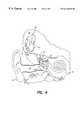
- FIG. 1is a functional schematic diagram of the ear, showing the manner in which an implantable microphone system is made through the use of a sensor implanted within the middle ear;
- FIG. 2is a simplified block diagram of the sensor of FIG. 1;
- FIG. 3shows one embodiment of the invention that includes the use of dual transducers operating in a continuous wave (CW) Doppler mode;
- CWcontinuous wave
- FIG. 4illustrates another embodiment of the invention that uses a split piezoelectric transducer
- FIG. 5depicts yet another embodiment of the invention utilizing a single transducer operating in a pulsed echo burst Doppler mode
- FIG. 6illustrates the derivation of the Doppler shift equation for use with the invention.
- FIG. 1there is shown a functional block diagram of an implantable microphone system 10 in accordance with the present invention. Also schematically shown in FIG. 1 are the major relevant components of the outer, middle and inner ear that typically play a role when using the invention.
- the outer earincludes the auricle 14 and the ear canal 16 .
- An acoustic pressure waverepresented in FIG. 1 by the short parallel lines 12 , is collected by the auricle 14 and funneled into the ear canal 16 .
- the “ear drum” 18At the end of the ear cannel 16 is the “ear drum” 18 , or in medical terms, the tympanic membrane 18 .
- the received acoustic wave 12causes the tympanic membrane 18 to vibrate, which vibration is coupled through three tiny bones, the malleus (“hammer”) 20 , the incus (“anvil”) 22 and the stapes (“stirrup”) 24 , to the oval window 30 .
- These bones of the middle earserve to filter and amplify the perceived acoustic wave 12 , causing the oval window 30 to articulate, or vibrate, in response to the acoustic wave 12 .
- Vibration of the oval windowsets up waves of fluid motion within the fluid contained within the snail-shaped cochlea 36 .
- Such fluid motionin turn, activates tiny hair cells (not shown in FIG. 1) that line the inside of the cochlea 36 .
- Activation of the hair cellscauses appropriate nerve impulses to be transferred through the spiral ganglion 40 to the brain, where they are perceived as sound.
- an implantable cochlear stimulator (ICS) 50may be implanted near the ear, and an electrode array 52 , having a plurality of spaced apart electrodes 54 thereon, is inserted into the cochlea 36 .
- ICS 50when used in conventional manner, e.g., as taught in the referenced patents, is coupled to an external microphone that senses sounds. Such coupling may occur through various means, but is usually achieved through an inductive coupling link with an external head piece, connected to a wearable processor. Such link also provides a way for power to be coupled into the implanted ICS 50 .
- the sounds sensed by the external microphoneare processed and converted to appropriate electrical stimuli that are selectively applied to the electrode contacts 54 of the electrode array 52 .
- Such electrical stimulibypass the defective hair cells and directly activate the nerves within the of the spiral ganglion, causing nerve impulses to be transferred to the brain, where they may be perceived as sound.
- the present inventionutilizes an implantable sensor 60 coupled to an implantable cochlear stimulator (ICS) 50 , as shown in FIG. 1, as an implantable microphone system 10 .
- the sensor 60is implanted so that at least a portion of it resides within the middle ear, but so that it does not physically come in contact with the moving elements that reside within the middle ear. That is, the sensor 60 does not physically come in contact with the tympanic membrane 18 , the malleus 20 , the incus 22 , the stapes 24 , or the oval window 30 .
- the sensor 60typically includes a transmitter portion 62 and a receiver portion 64 , each of which is appropriately controlled by a control circuit 66 .
- the transmitter portion 62generates an appropriate interrogation signal, either on a continuous wave (CW) or pulsed basis.
- Such interrogation signalis represented in FIG. 2 by the wavy arrow 63 and is hereafter referred to as the interrogation signal 63 .
- the interrogation signal 63is directed or focused so that it irradiates at least one of the moving elements 26 within the middle ear, i.e., the tympanic membrane 18 , the malleus 20 , the incus 22 , the stapes 24 , or the oval window 30 .
- a portion of the signal 63is reflected from the moving element 26 , and such reflected portion, represented in FIG. 2 as the wavy arrow 65 (and hereafter referred to as the reflected signal 65 ), is detected by the receiver portion 64 of the sensor 60 .
- the reflected signal 65is modulated in accordance with the degree of movement associated with the movable element 26 within the middle ear.
- an output signal 67is generated representative of the sensed movement of the movable element 26 , which movement, in turn, corresponds with the received acoustic pressure waves 12 (FIG. 1 ). That is, the output signal 67 comprises a signal representative of the sound that is received within the ear.
- the microphone system 10uses at least one of the moving elements 26 of the middle ear as its diaphragm in order to convert acoustic pressure waves to an output signal, e.g., an electrical output signal.
- transmitter portion 62 and the receiver portion 64 of the implantable sensor 60are shown in FIG. 2 as separate elements, it is to be understood that for some applications the transmitting and receiving functions may be carried out by the same element.
- One specific implementation of the inventioninvolves the use of ultrasonic acoustic Doppler shift.
- an acoustic transduceris used as the sensor 60 to interrogate any of the moving elements in the middle ear to derive a Doppler shift signal. This signal is detected and converted into an electrical signal that is proportional to the audio energy present at the tympanic membrane.
- the transducercan be used to detect tympanic membrane vibrations without making physical contact to any moving element. This approach provides the significant benefit of preserving the natural hearing mechanics of the individual while not loading any of the moving system with additional masses that would alter its natural acoustic response.
- Doppler shiftrelies on the property that a signal traveling through a media with a constant velocity of propagation and encountering a moving target is shifted by an amount proportional to the ratio of the velocity of that target and the velocity of propagation.
- ultrasoundacoustic waves
- the acoustic wavelengthsare relatively long and this places a constraint on the lower limit of detectable positional displacement of the target (the moving element within the middle ear).
- the use of an active rather than passive means to measure acoustic pressurewill cause a slight increase in power consumption.
- One advantage and benefit of this approachis that the normal ear mechanics are used to provide the hearing device.
- this methodmakes no physical contact to the moving parts, the normal motion of the middle ear components is not impeded. Since ultrasonic waves can travel through fluid as well as air, although with different velocities, this significantly reduces the sensitivity of this method to fluid or tissue accumulation in the middle ear.
- FIG. 2Other approaches used by the invention relate to the use of other types of signal emitters 62 (FIG. 2) that emit radiation 63 of a particular type, e.g., optical, infrared, RF, or other electromagnetic radiation.
- a suitable receiver 64compatible with receiving the type of radiation emitted, receives the radiation after such radiation has been affected by movement of at least one middle ear component 26 .
- “affected by”means the characteristics of the received signal, e.g., its amplitude, frequency, phase, energy content, morphology (shape), pulse width, or the like, are somehow influenced by the motion of one or more middle ear components 26 .
- FIG. 2While FIG.
- the receiver 64may be physically located anywhere within or without the middle ear so long as it is able to receive signals affected by the motion of the middle ear component 26 .
- FIG. 3One implementation of a microphone system 10 using ultrasonic Doppler shift is illustrated in FIG. 3 .
- the embodiment of the invention shown in FIG. 3includes the use of dual transducers 58 and 59 operating in a continuous wave (CW) Doppler mode.
- an implanted ICS 50 'is coupled to an implantable speech processor and power module 56 via a suitable connecting cable 57 .
- Dual acoustic piezoelectric CW Doppler transducers 58 and 59are coupled to the implanted speech processor and power module 56 .
- the transmit (TR) Doppler transducer 58interrogates one of the moving elements of the middle ear, e.g., the malleus 20 .
- the echois reflected back and detected by the receiving (REC) transducer 59 .
- the received echo signalis then amplified and demodulated to yield a signal, the output signal 67 , that can be used to represent the motion of the tympanic membrane 18 .
- the transmitting acoustic transducer 58 and the receiving acoustic transducer 59are both placed in a position to interrogate the head of the malleus 20 , although; any other moving target would be as effective.
- the transmitting transducercontinuously exposes the target to a sine wave signal f 0 .
- This signalis then amplified and processed into a usable speech signal by the electronics and software located in the system speech processor (which function as the control circuit 66 shown in FIG. 2 ).
- Dual-D CW Doppler transducersare available that provide both receiving and transmitting functions in a single package, and such may also be used to implement the microphone system of the present invention, as illustrated in FIG. 4 . These devices have been used in diagnostic ultrasound systems for several years and have the advantage that the transducers can be matched in phase and amplitude for improved Doppler performance.
- a split-D piezoelectric acoustic CW Doppler transducer 55is used as both a transmitter and a receiver. In operation, one half of the Doppler transducer 55 interrogates the moving elements of the middle ear while the other half receives the reflected signal. The reflected signal is processed to extract the motion signal and convert it into an acoustic microphone signal. If desired, a reflector element 53 may be added to the malleus 20 in order to enhance (e.g., increase the amplitude of) the reflected signal.
- FIG. 5A lower power version of the invention, effective for low frequency speech signals, is illustrated in FIG. 5 .
- the Doppler shift signalis obtained using a pulse/echo method employing a single Doppler transducer 51 .
- a sine wave burst signalis transmitted towards the target, e.g., the malleus 20 , for a short period of time (transmit burst time T1).
- the transmitteris then turned off and the same transducer 51 acts as a receiver for a “listen” time T2 (where T2 immediately follows T1), during which listen time the transducer 51 detects the reflected signal.
- T2immediately follows T1
- This signalcan then be used to represent the acoustic response, i.e., the output signal 67 (FIG. 2 ), of the microphone system 10 made in accordance with the invention using existing components of the user's ear. Care should be exercised, as required, with the pulse repetition frequency of the transmitter in order to avoid under sampling problems.
- a reflectormay be added to the moving middle ear component, as illustrated, e.g., in FIG. 4, to increase the intensity of the reflected signal.
- FIG. 6depicts the Doppler Shift equations that may be used with the invention.
- the amount of the Doppler shift resulting from a moving objectis determined by the wavelength of the interrogating signal and the displacement amplitude of the object.
- an acoustic signal 12may be represented by the expression A*sinf a , where A is the amplitude of the signal, and f a is the frequency of the acoustic signal 12 , and the sine function is used to model the varying nature of the acoustic signal 12 .
- the incoming signal 12impinges upon or strikes the tympanic membrane 18 , the tympanic membrane displaces or moves an amount ⁇ , where ⁇ is the amplitude of the displacement.
- the present inventionprovides an implantable microphone that may be used with a cochlear implant or other hearing aid system. More particularly, it is seen that the invention provides an implantable microphone system that advantageously utilizes many of the natural acoustic properties of the ear, such as its ability to use the outer ear to collect and direct sound into the ear canal, and its functioning middle ear components, to generate an electrical output signal 67 (see FIG. 2) of the microphone system that is representative of the sensed sound.
Landscapes
- Health & Medical Sciences (AREA)
- Otolaryngology (AREA)
- Engineering & Computer Science (AREA)
- Biomedical Technology (AREA)
- Nuclear Medicine, Radiotherapy & Molecular Imaging (AREA)
- Radiology & Medical Imaging (AREA)
- Life Sciences & Earth Sciences (AREA)
- Animal Behavior & Ethology (AREA)
- General Health & Medical Sciences (AREA)
- Public Health (AREA)
- Veterinary Medicine (AREA)
- Prostheses (AREA)
Abstract
Description
Claims (18)
Priority Applications (1)
| Application Number | Priority Date | Filing Date | Title |
|---|---|---|---|
| US09/375,462US6216040B1 (en) | 1998-08-31 | 1999-08-17 | Implantable microphone system for use with cochlear implantable hearing aids |
Applications Claiming Priority (2)
| Application Number | Priority Date | Filing Date | Title |
|---|---|---|---|
| US9859798P | 1998-08-31 | 1998-08-31 | |
| US09/375,462US6216040B1 (en) | 1998-08-31 | 1999-08-17 | Implantable microphone system for use with cochlear implantable hearing aids |
Publications (1)
| Publication Number | Publication Date |
|---|---|
| US6216040B1true US6216040B1 (en) | 2001-04-10 |
Family
ID=26794908
Family Applications (1)
| Application Number | Title | Priority Date | Filing Date |
|---|---|---|---|
| US09/375,462Expired - LifetimeUS6216040B1 (en) | 1998-08-31 | 1999-08-17 | Implantable microphone system for use with cochlear implantable hearing aids |
Country Status (1)
| Country | Link |
|---|---|
| US (1) | US6216040B1 (en) |
Cited By (59)
| Publication number | Priority date | Publication date | Assignee | Title |
|---|---|---|---|---|
| US6473651B1 (en)* | 1999-03-02 | 2002-10-29 | Advanced Bionics Corporation | Fluid filled microphone balloon to be implanted in the middle ear |
| US6505076B2 (en) | 2000-12-08 | 2003-01-07 | Advanced Bionics Corporation | Water-resistant, wideband microphone subassembly |
| US6572531B2 (en) | 2000-06-17 | 2003-06-03 | Alfred E. Mann Foundation For Scientific Reseach | Implantable middle ear implant |
| US6611718B2 (en) | 2000-06-19 | 2003-08-26 | Yitzhak Zilberman | Hybrid middle ear/cochlea implant system |
| US6636768B1 (en) | 2000-05-11 | 2003-10-21 | Advanced Bionics Corporation | Implantable mircophone system for use with cochlear implant devices |
| US6648813B2 (en) | 2000-06-17 | 2003-11-18 | Alfred E. Mann Foundation For Scientific Research | Hearing aid system including speaker implanted in middle ear |
| US6654638B1 (en)* | 2000-04-06 | 2003-11-25 | Cardiac Pacemakers, Inc. | Ultrasonically activated electrodes |
| US6694173B1 (en)* | 1999-11-12 | 2004-02-17 | Thomas Bende | Non-contact photoacoustic spectroscopy for photoablation control |
| US20040052391A1 (en)* | 2002-09-12 | 2004-03-18 | Micro Ear Technology, Inc. | System and method for selectively coupling hearing aids to electromagnetic signals |
| US6775389B2 (en) | 2001-08-10 | 2004-08-10 | Advanced Bionics Corporation | Ear auxiliary microphone for behind the ear hearing prosthetic |
| US20050091060A1 (en)* | 2003-10-23 | 2005-04-28 | Wing Thomas W. | Hearing aid for increasing voice recognition through voice frequency downshift and/or voice substitution |
| US20050216073A1 (en)* | 2004-03-15 | 2005-09-29 | Claude Jolly | Cochlear implant electrode with adjustable subdivision for middle ear functions |
| US20060013420A1 (en)* | 2002-09-16 | 2006-01-19 | Sacha Michael K | Switching structures for hearing aid |
| US7054691B1 (en) | 2002-01-02 | 2006-05-30 | Advanced Bionics Corporation | Partitioned implantable system |
| US20070113964A1 (en)* | 2001-12-10 | 2007-05-24 | Crawford Scott A | Small water-repellant microphone having improved acoustic performance and method of constructing same |
| US20070129632A1 (en)* | 2005-11-14 | 2007-06-07 | Spentech, Inc. | Ultrasound tympanoscope |
| US20070161848A1 (en)* | 2006-01-09 | 2007-07-12 | Cochlear Limited | Implantable interferometer microphone |
| AT503452B1 (en)* | 2002-03-01 | 2007-10-15 | Helms Jan Dr | hearing |
| US20080082141A1 (en)* | 2006-09-29 | 2008-04-03 | Cochlear Limited | Electrode assembly for a stimulating medical device |
| US20080159548A1 (en)* | 2007-01-03 | 2008-07-03 | Starkey Laboratories, Inc. | Wireless system for hearing communication devices providing wireless stereo reception modes |
| WO2009155650A1 (en) | 2008-06-25 | 2009-12-30 | Cochlear Limited | Enhanced performance implantable microphone system |
| EP2143385A1 (en)* | 2008-07-09 | 2010-01-13 | BIOTRONIK CRM Patent AG | Implantable measuring assembly |
| WO2010068984A1 (en)* | 2008-12-16 | 2010-06-24 | Cochlear Limited | Implantable microphone |
| US20100331913A1 (en)* | 2005-10-28 | 2010-12-30 | Mann Alfred E | Hybrid multi-function electrode array |
| US20110040350A1 (en)* | 2005-05-05 | 2011-02-17 | Griffith Glen A | FSK telemetry for cochlear implant |
| WO2011042569A2 (en) | 2011-01-11 | 2011-04-14 | Advanced Bionics Ag | At least partially implantable microphone |
| DE102009051771A1 (en) | 2009-10-29 | 2011-05-05 | Moldenhauer, Martin, Dipl.-Ing. | Completely implantatable optical microphone for use in e.g. implantable hearing aid, has sensor area fixed at ossicles such that movement of ossicles causes modulation of light guided into fiber when natural sound is caused at eardrum |
| WO2010151636A3 (en)* | 2009-06-24 | 2011-05-26 | SoundBeam LLC | Optical cochlear stimulation devices and methods |
| US20110137180A1 (en)* | 2009-12-04 | 2011-06-09 | Advanced Bionics AG, c/o Froriep Renggli | Systems and Methods for Fitting a Cochlear Implant System to a Patient Based on Stapedius Displacement |
| US20110144719A1 (en)* | 2009-06-18 | 2011-06-16 | SoundBeam LLC | Optically Coupled Cochlear Implant Systems and Methods |
| US8027733B1 (en)* | 2005-10-28 | 2011-09-27 | Advanced Bionics, Llc | Optimizing pitch allocation in a cochlear stimulation system |
| WO2012103126A1 (en)* | 2011-01-26 | 2012-08-02 | Brainstorm Audio, Llc | Hearing aid |
| AT505967B1 (en)* | 2003-11-14 | 2012-11-15 | Hearworks Pty Ltd | IMPLANTABLE ACOUSTIC SENSOR |
| US8971559B2 (en) | 2002-09-16 | 2015-03-03 | Starkey Laboratories, Inc. | Switching structures for hearing aid |
| US9036823B2 (en) | 2006-07-10 | 2015-05-19 | Starkey Laboratories, Inc. | Method and apparatus for a binaural hearing assistance system using monaural audio signals |
| US9277335B2 (en) | 2009-06-18 | 2016-03-01 | Earlens Corporation | Eardrum implantable devices for hearing systems and methods |
| US9358393B1 (en)* | 2004-11-09 | 2016-06-07 | Andres M. Lozano | Stimulation methods and systems for treating an auditory dysfunction |
| US9544700B2 (en) | 2009-06-15 | 2017-01-10 | Earlens Corporation | Optically coupled active ossicular replacement prosthesis |
| US9584931B2 (en) | 2010-09-03 | 2017-02-28 | Med-El Elektromedizinische Geraete Gmbh | Middle ear implantable microphone |
| US9774961B2 (en) | 2005-06-05 | 2017-09-26 | Starkey Laboratories, Inc. | Hearing assistance device ear-to-ear communication using an intermediate device |
| US10003379B2 (en) | 2014-05-06 | 2018-06-19 | Starkey Laboratories, Inc. | Wireless communication with probing bandwidth |
| US10212682B2 (en) | 2009-12-21 | 2019-02-19 | Starkey Laboratories, Inc. | Low power intermittent messaging for hearing assistance devices |
| US10492010B2 (en) | 2015-12-30 | 2019-11-26 | Earlens Corporations | Damping in contact hearing systems |
| US10511913B2 (en) | 2008-09-22 | 2019-12-17 | Earlens Corporation | Devices and methods for hearing |
| US10516951B2 (en) | 2014-11-26 | 2019-12-24 | Earlens Corporation | Adjustable venting for hearing instruments |
| US10516950B2 (en) | 2007-10-12 | 2019-12-24 | Earlens Corporation | Multifunction system and method for integrated hearing and communication with noise cancellation and feedback management |
| US10516949B2 (en) | 2008-06-17 | 2019-12-24 | Earlens Corporation | Optical electro-mechanical hearing devices with separate power and signal components |
| US10531206B2 (en) | 2014-07-14 | 2020-01-07 | Earlens Corporation | Sliding bias and peak limiting for optical hearing devices |
| US10555100B2 (en) | 2009-06-22 | 2020-02-04 | Earlens Corporation | Round window coupled hearing systems and methods |
| US10609492B2 (en) | 2010-12-20 | 2020-03-31 | Earlens Corporation | Anatomically customized ear canal hearing apparatus |
| US10779094B2 (en) | 2015-12-30 | 2020-09-15 | Earlens Corporation | Damping in contact hearing systems |
| US11058305B2 (en) | 2015-10-02 | 2021-07-13 | Earlens Corporation | Wearable customized ear canal apparatus |
| US11102594B2 (en) | 2016-09-09 | 2021-08-24 | Earlens Corporation | Contact hearing systems, apparatus and methods |
| US11166114B2 (en) | 2016-11-15 | 2021-11-02 | Earlens Corporation | Impression procedure |
| US11212626B2 (en) | 2018-04-09 | 2021-12-28 | Earlens Corporation | Dynamic filter |
| US11317224B2 (en) | 2014-03-18 | 2022-04-26 | Earlens Corporation | High fidelity and reduced feedback contact hearing apparatus and methods |
| US11350226B2 (en) | 2015-12-30 | 2022-05-31 | Earlens Corporation | Charging protocol for rechargeable hearing systems |
| US11516603B2 (en) | 2018-03-07 | 2022-11-29 | Earlens Corporation | Contact hearing device and retention structure materials |
| US11904167B2 (en) | 2019-03-27 | 2024-02-20 | Cochlear Limited | Auxiliary device connection |
Citations (6)
| Publication number | Priority date | Publication date | Assignee | Title |
|---|---|---|---|---|
| US4267410A (en) | 1977-11-03 | 1981-05-12 | The University Of Melbourne | Prosthesis |
| US4428377A (en) | 1980-03-06 | 1984-01-31 | Siemens Aktiengesellschaft | Method for the electrical stimulation of the auditory nerve and multichannel hearing prosthesis for carrying out the method |
| US4532930A (en) | 1983-04-11 | 1985-08-06 | Commonwealth Of Australia, Dept. Of Science & Technology | Cochlear implant system for an auditory prosthesis |
| US5603726A (en) | 1989-09-22 | 1997-02-18 | Alfred E. Mann Foundation For Scientific Research | Multichannel cochlear implant system including wearable speech processor |
| WO1997018689A1 (en) | 1995-11-13 | 1997-05-22 | Cochlear Limited | Implantable microphone for cochlear implants and the like |
| US5814095A (en) | 1996-09-18 | 1998-09-29 | Implex Gmbh Spezialhorgerate | Implantable microphone and implantable hearing aids utilizing same |
- 1999
- 1999-08-17USUS09/375,462patent/US6216040B1/ennot_activeExpired - Lifetime
Patent Citations (6)
| Publication number | Priority date | Publication date | Assignee | Title |
|---|---|---|---|---|
| US4267410A (en) | 1977-11-03 | 1981-05-12 | The University Of Melbourne | Prosthesis |
| US4428377A (en) | 1980-03-06 | 1984-01-31 | Siemens Aktiengesellschaft | Method for the electrical stimulation of the auditory nerve and multichannel hearing prosthesis for carrying out the method |
| US4532930A (en) | 1983-04-11 | 1985-08-06 | Commonwealth Of Australia, Dept. Of Science & Technology | Cochlear implant system for an auditory prosthesis |
| US5603726A (en) | 1989-09-22 | 1997-02-18 | Alfred E. Mann Foundation For Scientific Research | Multichannel cochlear implant system including wearable speech processor |
| WO1997018689A1 (en) | 1995-11-13 | 1997-05-22 | Cochlear Limited | Implantable microphone for cochlear implants and the like |
| US5814095A (en) | 1996-09-18 | 1998-09-29 | Implex Gmbh Spezialhorgerate | Implantable microphone and implantable hearing aids utilizing same |
Cited By (122)
| Publication number | Priority date | Publication date | Assignee | Title |
|---|---|---|---|---|
| US6473651B1 (en)* | 1999-03-02 | 2002-10-29 | Advanced Bionics Corporation | Fluid filled microphone balloon to be implanted in the middle ear |
| US6694173B1 (en)* | 1999-11-12 | 2004-02-17 | Thomas Bende | Non-contact photoacoustic spectroscopy for photoablation control |
| US6654638B1 (en)* | 2000-04-06 | 2003-11-25 | Cardiac Pacemakers, Inc. | Ultrasonically activated electrodes |
| US6636768B1 (en) | 2000-05-11 | 2003-10-21 | Advanced Bionics Corporation | Implantable mircophone system for use with cochlear implant devices |
| US6572531B2 (en) | 2000-06-17 | 2003-06-03 | Alfred E. Mann Foundation For Scientific Reseach | Implantable middle ear implant |
| US6648813B2 (en) | 2000-06-17 | 2003-11-18 | Alfred E. Mann Foundation For Scientific Research | Hearing aid system including speaker implanted in middle ear |
| US6611718B2 (en) | 2000-06-19 | 2003-08-26 | Yitzhak Zilberman | Hybrid middle ear/cochlea implant system |
| US6505076B2 (en) | 2000-12-08 | 2003-01-07 | Advanced Bionics Corporation | Water-resistant, wideband microphone subassembly |
| US8023677B2 (en) | 2001-08-10 | 2011-09-20 | Advanced Bionics, Llc | In the ear auxiliary microphone system for behind the ear hearing prosthetic |
| US6775389B2 (en) | 2001-08-10 | 2004-08-10 | Advanced Bionics Corporation | Ear auxiliary microphone for behind the ear hearing prosthetic |
| US20070173683A1 (en)* | 2001-08-10 | 2007-07-26 | Advanced Bionics Corporation | In the ear auxiliary microphone system for behind the ear hearing prosthetic |
| US7526096B2 (en) | 2001-08-10 | 2009-04-28 | Advanced Bionics, Llc | In the ear auxiliary microphone for behind the ear hearing prosthetic |
| US7970157B2 (en) | 2001-08-10 | 2011-06-28 | Advanced Bionics, Llc | In the ear auxiliary microphone system for behind the ear hearing prosthetic |
| US7003876B2 (en) | 2001-08-10 | 2006-02-28 | Advanced Bionics Corporation | Method of constructing an in the ear auxiliary microphone for behind the ear hearing prosthetic |
| US7769194B2 (en) | 2001-08-10 | 2010-08-03 | Advanced Bionics, Llc | In the ear auxiliary microphone for behind the ear hearing prosthetic |
| US7106873B1 (en) | 2001-08-10 | 2006-09-12 | Advanced Bionics Corporation | In the ear auxiliary microphone for behind the ear hearing prosthetic |
| US20070003089A1 (en)* | 2001-08-10 | 2007-01-04 | Advanced Bionics Corporation | In the ear auxiliary microphone for behind the ear hearing prosthetic |
| US20070001552A1 (en)* | 2001-08-10 | 2007-01-04 | Advanced Bionics Corporation | In the ear auxiliary microphone for behind the ear hearing prosthetic |
| US7167572B1 (en) | 2001-08-10 | 2007-01-23 | Advanced Bionics Corporation | In the ear auxiliary microphone system for behind the ear hearing prosthetic |
| US20070118011A1 (en)* | 2001-08-10 | 2007-05-24 | Advanced Bionics Corporation | In the ear auxiliary microphone system for behind the ear hearing prosthetic |
| US20070113964A1 (en)* | 2001-12-10 | 2007-05-24 | Crawford Scott A | Small water-repellant microphone having improved acoustic performance and method of constructing same |
| US7054691B1 (en) | 2002-01-02 | 2006-05-30 | Advanced Bionics Corporation | Partitioned implantable system |
| AT503452B1 (en)* | 2002-03-01 | 2007-10-15 | Helms Jan Dr | hearing |
| US7447325B2 (en) | 2002-09-12 | 2008-11-04 | Micro Ear Technology, Inc. | System and method for selectively coupling hearing aids to electromagnetic signals |
| US20040052391A1 (en)* | 2002-09-12 | 2004-03-18 | Micro Ear Technology, Inc. | System and method for selectively coupling hearing aids to electromagnetic signals |
| US8971559B2 (en) | 2002-09-16 | 2015-03-03 | Starkey Laboratories, Inc. | Switching structures for hearing aid |
| US8284970B2 (en) | 2002-09-16 | 2012-10-09 | Starkey Laboratories Inc. | Switching structures for hearing aid |
| US20060013420A1 (en)* | 2002-09-16 | 2006-01-19 | Sacha Michael K | Switching structures for hearing aid |
| US9215534B2 (en) | 2002-09-16 | 2015-12-15 | Starkey Laboratories, Inc. | Switching stuctures for hearing aid |
| US20050091060A1 (en)* | 2003-10-23 | 2005-04-28 | Wing Thomas W. | Hearing aid for increasing voice recognition through voice frequency downshift and/or voice substitution |
| AT505967B1 (en)* | 2003-11-14 | 2012-11-15 | Hearworks Pty Ltd | IMPLANTABLE ACOUSTIC SENSOR |
| US8126572B2 (en)* | 2004-03-15 | 2012-02-28 | Med-El Elektromedizinische Geraete Gmbh | Cochlear implant electrode with adjustable subdivision for middle ear functions |
| AU2005293248B2 (en)* | 2004-03-15 | 2010-08-26 | Med-El Elektromedizinische Geraete Gmbh | Cochlear implant electrode with adjustable subdivision for middle ear functions |
| US20050216073A1 (en)* | 2004-03-15 | 2005-09-29 | Claude Jolly | Cochlear implant electrode with adjustable subdivision for middle ear functions |
| US9358393B1 (en)* | 2004-11-09 | 2016-06-07 | Andres M. Lozano | Stimulation methods and systems for treating an auditory dysfunction |
| US20110040350A1 (en)* | 2005-05-05 | 2011-02-17 | Griffith Glen A | FSK telemetry for cochlear implant |
| US9774961B2 (en) | 2005-06-05 | 2017-09-26 | Starkey Laboratories, Inc. | Hearing assistance device ear-to-ear communication using an intermediate device |
| US20100331913A1 (en)* | 2005-10-28 | 2010-12-30 | Mann Alfred E | Hybrid multi-function electrode array |
| US8027733B1 (en)* | 2005-10-28 | 2011-09-27 | Advanced Bionics, Llc | Optimizing pitch allocation in a cochlear stimulation system |
| US8295937B2 (en) | 2005-10-28 | 2012-10-23 | Advanced Bionics, Llc | Optimizing pitch allocation in a cochlear stimulation system |
| US20070129632A1 (en)* | 2005-11-14 | 2007-06-07 | Spentech, Inc. | Ultrasound tympanoscope |
| US7771356B2 (en)* | 2005-11-14 | 2010-08-10 | Spentech, Inc. | Ultrasound tympanoscope |
| US20070161848A1 (en)* | 2006-01-09 | 2007-07-12 | Cochlear Limited | Implantable interferometer microphone |
| US8014871B2 (en) | 2006-01-09 | 2011-09-06 | Cochlear Limited | Implantable interferometer microphone |
| US11064302B2 (en) | 2006-07-10 | 2021-07-13 | Starkey Laboratories, Inc. | Method and apparatus for a binaural hearing assistance system using monaural audio signals |
| US9036823B2 (en) | 2006-07-10 | 2015-05-19 | Starkey Laboratories, Inc. | Method and apparatus for a binaural hearing assistance system using monaural audio signals |
| US10469960B2 (en) | 2006-07-10 | 2019-11-05 | Starkey Laboratories, Inc. | Method and apparatus for a binaural hearing assistance system using monaural audio signals |
| US10051385B2 (en) | 2006-07-10 | 2018-08-14 | Starkey Laboratories, Inc. | Method and apparatus for a binaural hearing assistance system using monaural audio signals |
| US11678128B2 (en) | 2006-07-10 | 2023-06-13 | Starkey Laboratories, Inc. | Method and apparatus for a binaural hearing assistance system using monaural audio signals |
| US9510111B2 (en) | 2006-07-10 | 2016-11-29 | Starkey Laboratories, Inc. | Method and apparatus for a binaural hearing assistance system using monaural audio signals |
| US10728678B2 (en) | 2006-07-10 | 2020-07-28 | Starkey Laboratories, Inc. | Method and apparatus for a binaural hearing assistance system using monaural audio signals |
| US7966077B2 (en)* | 2006-09-29 | 2011-06-21 | Cochlear Limited | Electrode assembly for a stimulating medical device |
| US8452411B2 (en) | 2006-09-29 | 2013-05-28 | Cochlear Limited | Electrode assembly for a stimulating medical device |
| US20080082141A1 (en)* | 2006-09-29 | 2008-04-03 | Cochlear Limited | Electrode assembly for a stimulating medical device |
| US20080159548A1 (en)* | 2007-01-03 | 2008-07-03 | Starkey Laboratories, Inc. | Wireless system for hearing communication devices providing wireless stereo reception modes |
| US11218815B2 (en) | 2007-01-03 | 2022-01-04 | Starkey Laboratories, Inc. | Wireless system for hearing communication devices providing wireless stereo reception modes |
| US11765526B2 (en) | 2007-01-03 | 2023-09-19 | Starkey Laboratories, Inc. | Wireless system for hearing communication devices providing wireless stereo reception modes |
| US8041066B2 (en) | 2007-01-03 | 2011-10-18 | Starkey Laboratories, Inc. | Wireless system for hearing communication devices providing wireless stereo reception modes |
| US8515114B2 (en) | 2007-01-03 | 2013-08-20 | Starkey Laboratories, Inc. | Wireless system for hearing communication devices providing wireless stereo reception modes |
| US9854369B2 (en) | 2007-01-03 | 2017-12-26 | Starkey Laboratories, Inc. | Wireless system for hearing communication devices providing wireless stereo reception modes |
| US10511918B2 (en) | 2007-01-03 | 2019-12-17 | Starkey Laboratories, Inc. | Wireless system for hearing communication devices providing wireless stereo reception modes |
| US9282416B2 (en) | 2007-01-03 | 2016-03-08 | Starkey Laboratories, Inc. | Wireless system for hearing communication devices providing wireless stereo reception modes |
| US12212930B2 (en) | 2007-01-03 | 2025-01-28 | Starkey Laboratories, Inc. | Wireless system for hearing communication devices providing wireless stereo reception modes |
| US10863286B2 (en) | 2007-10-12 | 2020-12-08 | Earlens Corporation | Multifunction system and method for integrated hearing and communication with noise cancellation and feedback management |
| US10516950B2 (en) | 2007-10-12 | 2019-12-24 | Earlens Corporation | Multifunction system and method for integrated hearing and communication with noise cancellation and feedback management |
| US11483665B2 (en) | 2007-10-12 | 2022-10-25 | Earlens Corporation | Multifunction system and method for integrated hearing and communication with noise cancellation and feedback management |
| US11310605B2 (en) | 2008-06-17 | 2022-04-19 | Earlens Corporation | Optical electro-mechanical hearing devices with separate power and signal components |
| US10516949B2 (en) | 2008-06-17 | 2019-12-24 | Earlens Corporation | Optical electro-mechanical hearing devices with separate power and signal components |
| WO2009155650A1 (en) | 2008-06-25 | 2009-12-30 | Cochlear Limited | Enhanced performance implantable microphone system |
| EP2143385A1 (en)* | 2008-07-09 | 2010-01-13 | BIOTRONIK CRM Patent AG | Implantable measuring assembly |
| US10743110B2 (en) | 2008-09-22 | 2020-08-11 | Earlens Corporation | Devices and methods for hearing |
| US10511913B2 (en) | 2008-09-22 | 2019-12-17 | Earlens Corporation | Devices and methods for hearing |
| US11057714B2 (en) | 2008-09-22 | 2021-07-06 | Earlens Corporation | Devices and methods for hearing |
| US10516946B2 (en) | 2008-09-22 | 2019-12-24 | Earlens Corporation | Devices and methods for hearing |
| WO2010068984A1 (en)* | 2008-12-16 | 2010-06-24 | Cochlear Limited | Implantable microphone |
| US8679031B2 (en) | 2008-12-16 | 2014-03-25 | Cochlear Limited | Hearing prosthesis with integrated sensors for measuring pressure in a cochlea |
| US9544700B2 (en) | 2009-06-15 | 2017-01-10 | Earlens Corporation | Optically coupled active ossicular replacement prosthesis |
| US20110144719A1 (en)* | 2009-06-18 | 2011-06-16 | SoundBeam LLC | Optically Coupled Cochlear Implant Systems and Methods |
| US10286215B2 (en) | 2009-06-18 | 2019-05-14 | Earlens Corporation | Optically coupled cochlear implant systems and methods |
| US9277335B2 (en) | 2009-06-18 | 2016-03-01 | Earlens Corporation | Eardrum implantable devices for hearing systems and methods |
| US10555100B2 (en) | 2009-06-22 | 2020-02-04 | Earlens Corporation | Round window coupled hearing systems and methods |
| US11323829B2 (en) | 2009-06-22 | 2022-05-03 | Earlens Corporation | Round window coupled hearing systems and methods |
| WO2010151636A3 (en)* | 2009-06-24 | 2011-05-26 | SoundBeam LLC | Optical cochlear stimulation devices and methods |
| US8845705B2 (en) | 2009-06-24 | 2014-09-30 | Earlens Corporation | Optical cochlear stimulation devices and methods |
| US20110152976A1 (en)* | 2009-06-24 | 2011-06-23 | SoundBeam LLC | Optical Cochlear Stimulation Devices and Methods |
| DE102009051771A1 (en) | 2009-10-29 | 2011-05-05 | Moldenhauer, Martin, Dipl.-Ing. | Completely implantatable optical microphone for use in e.g. implantable hearing aid, has sensor area fixed at ossicles such that movement of ossicles causes modulation of light guided into fiber when natural sound is caused at eardrum |
| US20110137180A1 (en)* | 2009-12-04 | 2011-06-09 | Advanced Bionics AG, c/o Froriep Renggli | Systems and Methods for Fitting a Cochlear Implant System to a Patient Based on Stapedius Displacement |
| WO2011069020A1 (en)* | 2009-12-04 | 2011-06-09 | Advanced Bionics Ag | Systems and methods for fitting a cochlear implant system to a patient based on stapedius displacement |
| US10212682B2 (en) | 2009-12-21 | 2019-02-19 | Starkey Laboratories, Inc. | Low power intermittent messaging for hearing assistance devices |
| US11019589B2 (en) | 2009-12-21 | 2021-05-25 | Starkey Laboratories, Inc. | Low power intermittent messaging for hearing assistance devices |
| US9584931B2 (en) | 2010-09-03 | 2017-02-28 | Med-El Elektromedizinische Geraete Gmbh | Middle ear implantable microphone |
| US10609492B2 (en) | 2010-12-20 | 2020-03-31 | Earlens Corporation | Anatomically customized ear canal hearing apparatus |
| US11153697B2 (en) | 2010-12-20 | 2021-10-19 | Earlens Corporation | Anatomically customized ear canal hearing apparatus |
| US11743663B2 (en) | 2010-12-20 | 2023-08-29 | Earlens Corporation | Anatomically customized ear canal hearing apparatus |
| WO2011042569A3 (en)* | 2011-01-11 | 2011-12-01 | Advanced Bionics Ag | At least partially implantable microphone |
| WO2011042569A2 (en) | 2011-01-11 | 2011-04-14 | Advanced Bionics Ag | At least partially implantable microphone |
| US8879755B2 (en) | 2011-01-11 | 2014-11-04 | Advanced Bionics Ag | At least partially implantable sound pick-up device with ultrasound emitter |
| US8442253B2 (en) | 2011-01-26 | 2013-05-14 | Brainstorm Audio, Llc | Hearing aid |
| US9332356B2 (en) | 2011-01-26 | 2016-05-03 | Brainstorm Audio, Llc | Hearing aid |
| WO2012103126A1 (en)* | 2011-01-26 | 2012-08-02 | Brainstorm Audio, Llc | Hearing aid |
| US11317224B2 (en) | 2014-03-18 | 2022-04-26 | Earlens Corporation | High fidelity and reduced feedback contact hearing apparatus and methods |
| US10003379B2 (en) | 2014-05-06 | 2018-06-19 | Starkey Laboratories, Inc. | Wireless communication with probing bandwidth |
| US11800303B2 (en) | 2014-07-14 | 2023-10-24 | Earlens Corporation | Sliding bias and peak limiting for optical hearing devices |
| US11259129B2 (en) | 2014-07-14 | 2022-02-22 | Earlens Corporation | Sliding bias and peak limiting for optical hearing devices |
| US10531206B2 (en) | 2014-07-14 | 2020-01-07 | Earlens Corporation | Sliding bias and peak limiting for optical hearing devices |
| US11252516B2 (en) | 2014-11-26 | 2022-02-15 | Earlens Corporation | Adjustable venting for hearing instruments |
| US10516951B2 (en) | 2014-11-26 | 2019-12-24 | Earlens Corporation | Adjustable venting for hearing instruments |
| US11058305B2 (en) | 2015-10-02 | 2021-07-13 | Earlens Corporation | Wearable customized ear canal apparatus |
| US11070927B2 (en) | 2015-12-30 | 2021-07-20 | Earlens Corporation | Damping in contact hearing systems |
| US11350226B2 (en) | 2015-12-30 | 2022-05-31 | Earlens Corporation | Charging protocol for rechargeable hearing systems |
| US10492010B2 (en) | 2015-12-30 | 2019-11-26 | Earlens Corporations | Damping in contact hearing systems |
| US11337012B2 (en) | 2015-12-30 | 2022-05-17 | Earlens Corporation | Battery coating for rechargable hearing systems |
| US11516602B2 (en) | 2015-12-30 | 2022-11-29 | Earlens Corporation | Damping in contact hearing systems |
| US10779094B2 (en) | 2015-12-30 | 2020-09-15 | Earlens Corporation | Damping in contact hearing systems |
| US11540065B2 (en) | 2016-09-09 | 2022-12-27 | Earlens Corporation | Contact hearing systems, apparatus and methods |
| US11102594B2 (en) | 2016-09-09 | 2021-08-24 | Earlens Corporation | Contact hearing systems, apparatus and methods |
| US11166114B2 (en) | 2016-11-15 | 2021-11-02 | Earlens Corporation | Impression procedure |
| US11671774B2 (en) | 2016-11-15 | 2023-06-06 | Earlens Corporation | Impression procedure |
| US11516603B2 (en) | 2018-03-07 | 2022-11-29 | Earlens Corporation | Contact hearing device and retention structure materials |
| US11564044B2 (en) | 2018-04-09 | 2023-01-24 | Earlens Corporation | Dynamic filter |
| US11212626B2 (en) | 2018-04-09 | 2021-12-28 | Earlens Corporation | Dynamic filter |
| US11904167B2 (en) | 2019-03-27 | 2024-02-20 | Cochlear Limited | Auxiliary device connection |
Similar Documents
| Publication | Publication Date | Title |
|---|---|---|
| US6216040B1 (en) | Implantable microphone system for use with cochlear implantable hearing aids | |
| JP3174324B2 (en) | Ultrasonic bone conduction hearing aid and hearing aid method | |
| US5061282A (en) | Cochlear implant auditory prosthesis | |
| US8014871B2 (en) | Implantable interferometer microphone | |
| US5899847A (en) | Implantable middle-ear hearing assist system using piezoelectric transducer film | |
| US6010532A (en) | Dual path implantable hearing assistance device | |
| US6161046A (en) | Totally implantable cochlear implant for improvement of partial and total sensorineural hearing loss | |
| US7616771B2 (en) | Acoustic coupler for skin contact hearing enhancement devices | |
| US6636768B1 (en) | Implantable mircophone system for use with cochlear implant devices | |
| US8532322B2 (en) | Bone conduction device for a single sided deaf recipient | |
| US6193645B1 (en) | Electromagnetic input transducers for middle ear sensing | |
| US5584869A (en) | Failure detection in auditory response stimulators | |
| US8706248B2 (en) | Directional sound processing in a cochlear implant | |
| US20070154030A1 (en) | Implantable hearing aid | |
| US20020026125A1 (en) | Device for electromechanical stimulation and testing of hearing | |
| WO1998006238A1 (en) | Piezoelectric film transducer for use in an implantable hearing system | |
| KR19990082641A (en) | Improved biocensor transducer | |
| WO2002083034A3 (en) | Hearing aid with internal acoustic middle ear transducer | |
| KR101334912B1 (en) | Device for cochlear implant with sensor and electrode | |
| NL8601307A (en) | IMPLANTABLE ELECTROMAGNETIC HEARING AID WITH MIDDLE EAR CONDUCTION. | |
| JPS621726B2 (en) | ||
| CN105214212A (en) | Comprise the auditory prosthesis of implantable part | |
| JP2016534785A (en) | Cochlear implant electrode array comprising a receptor and a sensor | |
| EP2577984A1 (en) | Intra-oral tissue conduction microphone | |
| WO2011069020A1 (en) | Systems and methods for fitting a cochlear implant system to a patient based on stapedius displacement |
Legal Events
| Date | Code | Title | Description |
|---|---|---|---|
| AS | Assignment | Owner name:ADVANCED BIONICS CORPORATION, CALIFORNIA Free format text:ASSIGNMENT OF ASSIGNORS INTEREST;ASSIGNOR:HARRISON, WILLIAM VANBROOKS;REEL/FRAME:010243/0032 Effective date:19990816 | |
| STCF | Information on status: patent grant | Free format text:PATENTED CASE | |
| FEPP | Fee payment procedure | Free format text:PAT HOLDER NO LONGER CLAIMS SMALL ENTITY STATUS, ENTITY STATUS SET TO UNDISCOUNTED (ORIGINAL EVENT CODE: STOL); ENTITY STATUS OF PATENT OWNER: LARGE ENTITY | |
| FPAY | Fee payment | Year of fee payment:4 | |
| AS | Assignment | Owner name:BOSTON SCIENTIFIC NEUROMODULATION CORPORATION, CAL Free format text:CHANGE OF NAME;ASSIGNOR:ADVANCED BIONICS CORPORATION;REEL/FRAME:020299/0200 Effective date:20071116 | |
| AS | Assignment | Owner name:BOSTON SCIENTIFIC NEUROMODULATION CORPORATION, CAL Free format text:CHANGE OF NAME;ASSIGNOR:ADVANCED BIONICS CORPORATION;REEL/FRAME:020309/0361 Effective date:20071116 | |
| AS | Assignment | Owner name:ADVANCED BIONICS, LLC, CALIFORNIA Free format text:ASSIGNMENT OF ASSIGNORS INTEREST;ASSIGNOR:BOSTON SCIENTIFIC NEUROMODULATION CORPORATION;REEL/FRAME:020340/0713 Effective date:20080107 Owner name:ADVANCED BIONICS, LLC,CALIFORNIA Free format text:ASSIGNMENT OF ASSIGNORS INTEREST;ASSIGNOR:BOSTON SCIENTIFIC NEUROMODULATION CORPORATION;REEL/FRAME:020340/0713 Effective date:20080107 | |
| FPAY | Fee payment | Year of fee payment:8 | |
| FPAY | Fee payment | Year of fee payment:12 | |
| AS | Assignment | Owner name:ADVANCED BIONICS AG, SWITZERLAND Free format text:ASSIGNMENT OF ASSIGNORS INTEREST;ASSIGNOR:ADVANCED BIONICS, LLC;REEL/FRAME:051063/0829 Effective date:20111130 |