US6216011B1 - Mobile unit for accommodating network mute feature in wireless telecommunications systems - Google Patents
Mobile unit for accommodating network mute feature in wireless telecommunications systemsDownload PDFInfo
- Publication number
- US6216011B1 US6216011B1US09/159,366US15936698AUS6216011B1US 6216011 B1US6216011 B1US 6216011B1US 15936698 AUS15936698 AUS 15936698AUS 6216011 B1US6216011 B1US 6216011B1
- Authority
- US
- United States
- Prior art keywords
- mobile unit
- network mute
- network
- party
- signal
- Prior art date
- Legal status (The legal status is an assumption and is not a legal conclusion. Google has not performed a legal analysis and makes no representation as to the accuracy of the status listed.)
- Expired - Lifetime
Links
Images


Classifications
- H—ELECTRICITY
- H04—ELECTRIC COMMUNICATION TECHNIQUE
- H04W—WIRELESS COMMUNICATION NETWORKS
- H04W4/00—Services specially adapted for wireless communication networks; Facilities therefor
- H04W4/06—Selective distribution of broadcast services, e.g. multimedia broadcast multicast service [MBMS]; Services to user groups; One-way selective calling services
- H—ELECTRICITY
- H04—ELECTRIC COMMUNICATION TECHNIQUE
- H04M—TELEPHONIC COMMUNICATION
- H04M3/00—Automatic or semi-automatic exchanges
- H04M3/42—Systems providing special services or facilities to subscribers
- H04M3/56—Arrangements for connecting several subscribers to a common circuit, i.e. affording conference facilities
- H—ELECTRICITY
- H04—ELECTRIC COMMUNICATION TECHNIQUE
- H04M—TELEPHONIC COMMUNICATION
- H04M2203/00—Aspects of automatic or semi-automatic exchanges
- H04M2203/20—Aspects of automatic or semi-automatic exchanges related to features of supplementary services
- H04M2203/2088—Call or conference reconnect, e.g. resulting from isdn terminal portability
- H—ELECTRICITY
- H04—ELECTRIC COMMUNICATION TECHNIQUE
- H04M—TELEPHONIC COMMUNICATION
- H04M2207/00—Type of exchange or network, i.e. telephonic medium, in which the telephonic communication takes place
- H04M2207/18—Type of exchange or network, i.e. telephonic medium, in which the telephonic communication takes place wireless networks
- H—ELECTRICITY
- H04—ELECTRIC COMMUNICATION TECHNIQUE
- H04M—TELEPHONIC COMMUNICATION
- H04M2242/00—Special services or facilities
- H04M2242/04—Special services or facilities for emergency applications
- H—ELECTRICITY
- H04—ELECTRIC COMMUNICATION TECHNIQUE
- H04M—TELEPHONIC COMMUNICATION
- H04M3/00—Automatic or semi-automatic exchanges
- H04M3/42—Systems providing special services or facilities to subscribers
- H04M3/56—Arrangements for connecting several subscribers to a common circuit, i.e. affording conference facilities
- H04M3/568—Arrangements for connecting several subscribers to a common circuit, i.e. affording conference facilities audio processing specific to telephonic conferencing, e.g. spatial distribution, mixing of participants
Definitions
- This inventionrelates to telecommunications systems, and more particularly to the mute function associated with mobile units deployed in wireless telecommunications systems.
- a well known staple of the business worldis the conference call.
- a conference callis a meeting in which typically one or more parties participates in the discussion via telephone.
- improvements have been madethe quality of a conference call is often a deterrent to a successful meeting.
- the less-than-optimal quality of a conference call, coupled with the ambient background noise associated with transmission by a wireless telecommunications network,is sometimes so intolerable that mobile conference call participants are asked to drop off from the call so that the rest of the participants may discuss matters with decreased distraction.
- most mobile unitshave a “mute” function, this function only deactivates the microphone of the mobile unit. Ambient noise associated with wireless transmission still flows to the other party via the wireless telecommunications network.
- a network mute function buttonis found on a mobile unit.
- the network mute functionis used by a mobile user during participation in a conference call in which the other parties participating in the call are subject to the ambient noise associated with the mobile user's environment and the wireless telecommunications network.
- Activation of the network mute functioncauses the mobile unit to send a signaling message to the mobile switching center which decouples a voice path interconnecting the mobile user to another party.
- the mobile switching centersubsequently interconnects the voice path to a noise generator.
- the noise generatorprovides non-obtrusive background noise which is heard only by the other party. The purpose of the background noise is to assure the other party that the mobile user is still on the line and can hear the conversation.
- the network mute functionactually mutes the mobile unit microphone and noise associated with the wireless telecommunications systems.
- the network mute functionnot only mutes the microphone with the mobile unit but also eliminates wireless network noise associated with the wireless telecommunications system interconnecting the mobile user to another party.
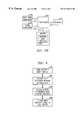
- FIGS. 1A and 1Bare simplified block diagrams of a wireless telecommunications system in which the present invention may be practiced;
- FIG. 2Ais a front view of a typical mobile handset with mute function
- FIG. 2Bis a simplified block diagram of the internal components of the mobile handset shown in FIG. 2A;
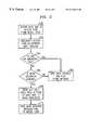
- FIG. 3is a flow diagram depicting the steps performed by a mobile handset for activating a network mute function
- FIG. 4is a flow diagram depicting the steps performed by a wireless telecommunications system for activating a network mute function
- FIG. 5is a flow diagram depicting the steps performed by a wireless telecommunications system for dial access code activation of a network mute function
- FIG. 6is a flow diagram depicting the steps performed by a wireless telecommunications system for deactivation of a network mute function.
- FIG. 1Ashows wireless telecommunications system 100 including mobile unit 110 , base station 120 and mobile switching center 140 . Also shown is public switched telephone network (PSTN) 180 which serves all other wireline and wireless subscribers.
- PSTNpublic switched telephone network
- mobile unit 110(including network mute button 113 ) is served by base station 120 .
- Base station 120includes processor 122 interconnected to air interface 123 , radio resource interface 124 and database 126 via links 121 , 125 and 127 , respectively. Also shown is antenna 128 interconnected to air interface 123 via link 131 . Air interface 123 is interconnected to radio resources 124 via link 133 .
- Mobile switching center (MSC) 140comprises controller 142 interconnected to announcement/tone generation circuit 160 via link 141 .
- Timeslot interchanger (TSI) 144is interconnected to the controller via link 143 .
- voice decoder 146 and noise generator 148interconnected to TSI 144 via voice paths.
- voice pathsare established from radio resources 124 through TSI 144 to PSTN 180 .
- non-muted voice paths 151 , 153are shown emanating from radio resource interface 124 , passing through voice decoder 146 and terminating at PSTN 180 .
- voice path 151interconnects the mobile user to the called party served by the PSTN while voice path 153 interconnects the called party to the mobile user.
- voice paths 151 , 153could have been shown as a single bidirectional voice path.
- Voice decoder 146is used in digital wireless systems (e.g., CDMA or TDMA systems) for processing the normally compressed voice signals received.
- the voice decoderdecompresses the voice signals and converts these signals to a pulse code modulation format recognizable by the PSTN.
- voice decoder 146is not present in analog wireless telecommunications systems. Also shown is network me voice path 155 and its counterpart voice path 157 . In this case, voice path 155 (from the mobile user to the called party) emanates from radio resource interface 124 , passes through voice decoder 146 and is opened prior to connection to the called party served by the PSTN. The remaining portion of voice path 155 (that is, the portion of the path still interconnected to the called party) is interconnected to link 149 .
- Link 149emanating from noise generator 148 , is interconnected to voice path 155 so that non-obtrusive background noise is supplied to voice path 155 by the noise generator before termination to the called party.
- voice path 155By opening voice path 155 within TSI 144 , the ambient noise associated with the mobile user's environment and wireless transmission is not passed to the called party served by the PSTN. Instead the called party hears non-obtrusive background noise so that the called party is aware that the mobile user is still on the line without being subject to the disturbances associated with wireless transmission.
- voice path 157 interconnecting the called party to the mobile useris not opened. In other words, the mobile user can hear all conversation initiated by the called party.
- FIG. 1Bshows an alternative embodiment for TSI 144 , voice decoder 146 and noise generator 148 .
- the noise generatoris disposed within the voice decoder.
- first leg 175 of a network muted voice pathterminates in voice decoder 146 while second leg 177 of the network muted voice path emanates from noise generator 148 and terminates to the called party.
- Voice path 179 interconnecting the called party to the mobile unitis not affected by the network mute function. In other words, the mobile unit user is able to hear all transmissions originated by the called party.
- FIG. 2Ashows a front view of a typical mobile unit 200 .
- Mobile unit 200comprises visual display screen 202 , antenna 204 , a plurality of function buttons, collectively referenced as function buttons 206 , and mute network function button 208 .
- FIG. 2Bshows the internal components of mobile unit 200 shown in FIG. 2 A. More particularly, mobile unit 200 comprises processor 210 interconnected to memory 212 via link 213 . Radio frequency receiver 214 , dual tone multifrequency (DTMF) tone generator 216 and signal generator 218 are shown interconnected to the processor via links 215 , 217 and 219 , respectively. Processor 210 is responsible for administering and managing all functions of the mobile unit. Radio receiver 214 receives radio frequency signals via antenna 204 . DTMF tone generator 216 is interconnected to function buttons 206 for generating a specific DTMF tone for each button. DTMF tone generator 216 is also interconnected and generates a particular DTMF tone for network mute function button 208 . Signal generator 218 extends radio frequency signals from the mobile unit to the PSTN via antenna 204 . Memory 212 stores data associated with mobile unit 200 .
- Radio frequency receiver 214receives radio frequency signals via antenna 204 .
- DTMF tone generator 216is interconnected to function buttons 206 for generating
- memory 212includes memory segment 220 which stores a signaling protocol relating to operation of network mute function button 208 . More particularly, the signaling protocol stored in segment 220 is accessed by processor 210 upon receipt of a network mute request. When the network mute button is activated, processor 210 extends a network mute request to a serving mobile switching center (via a base station) in an established signaling format such as IS 95, “blank and burst” signaling or IS 136.
- an established signaling formatsuch as IS 95, “blank and burst” signaling or IS 136.
- FIG. 3is a flow diagram depicting the steps performed in a mobile unit for activation of the network mute function.
- the processbegins in step 300 in which the user of the mobile unit activates the network mute feature by depressing a mute button.
- a DTMF tone corresponding to the network mute functionis received in the processor of the mobile unit.
- DTMF tone generator 216generates a specific tone associated with network mute function button 208 and extends this specific tone to processor 210 over link 217 .
- the processorreceives the mute request and accesses its memory to retrieve a signaling protocol associated with the network mute function.
- processor 210accesses memory segment 220 for the network mute signaling protocol.
- processor 210instructs signal generator 218 to extend a network mute request signal to a serving base station.
- the network mute request signalis extended to the serving base station via a radio frequency protocol such as IS 95, IS 136, “blank and burst” signaling or direct transfer application part (DTAP) signaling.
- a radio frequency protocolsuch as IS 95, IS 136, “blank and burst” signaling or direct transfer application part (DTAP) signaling.
- FIG. 4is a flow diagram depicting the steps performed in a wireless telecommunications system for activation of the network mute function. For purposes of example, assume that the network mute function is activated in wireless telecommunications system 100 .
- a base stationreceives a network mute request signal from a mobile unit and extends this request to its serving mobile switching center.
- base station 120receives a network request mute signal and extends it to MSC 140 .
- MSC 140receives the network mute request. If the mobile user is roaming, standard inter-MSC handoff signaling is used to ensure that the serving MSC receives the network mute request from the mobile user.
- step 404the MSC determines whether the ongoing call is an emergency (e.g., E911) call. If the outcome of decision step 404 is a “YES” determination, the process continues to step 405 in which the network mute request is denied and the MSC issues a tone or announcement to the mobile user indicating such. If the outcome of decision step 404 is a “NO” determination, the process continues to step 406 in which the MSC determines whether the noise generator is available to handle the newly received network mute request. MSC 140 checks on the status of the noise generator because these resources are intentionally limited to minimize space requirements.
- E911emergency
- step 406If the outcome of decision step 406 is a “NO” determination, the process returns to step 405 in which the MSC denies the network mute request and issues an announcement or tone to the mobile user via announcement/tone circuit 160 .
- the announcement or tone issued to the mobile user via serving base station 120may indicate that the network mute function is not available but that the user may try again at a later time.
- the processcontinues to step 408 in which the MSC opens the voice path from the mobile unit to the PSTN (or the called party) but holds the voice path resources.
- the MSCactivates a path from a portion of the open voice path to a noise generator for the insertion of non-obtrusive background noise to be played to the called party.
- the processcontinues to step 410 in which a network mute activated message or tone is issued to the mobile user via the announcement/tone circuit for indicating that the network mute function has been turned “on” and will remain active until the user elects to deactivate the function.
- a network mute signalmay be visually displayed on the mobile unit.
- FIG. 5is a flow diagram depicting the steps performed in a wireless telecommunications system in which the network mute function is activated by a dial access code.
- a dial access codeis a predetermined set of signals (e.g., *77) which indicates to the wireless telecommunications system that a mobile unit user wishes to invoke the network mute feature.
- Dial access code activation of a network mute featurebegins in step 500 in which the serving MSC receives a dialed access code from a mobile user. This particular access code identifies activation of a network mute function.
- the MSCrecognizes the access code as the network mute request.
- decision step 504the MSC determines if the ongoing call is an E911 call. If the outcome of decision step 504 is a “YES” determination, the process continues to step 505 in which the network mute function request is denied. An announcement or tone from circuit 160 is issued to the mobile user to indicate the denial.
- decision step 506the MSC determines if a noise generator is available to satisfy the network mute request. If the outcome of decision step 504 is a “NO” determination, the process returns to step 505 in which the network mute request is denied and an announcement or tone indicating such is issued to the mobile user. If the outcome of decision step 506 is a “YES” determination, the MSC opens the voice path interconnecting the mobile user to a called party served by the PSTN but holds the voice path resource. After opening the voice path to the called party, the called party is interconnected to a path associated with a noise generator.
- step 508activation of the network mute function is confirmed by issuing an announcement or tone to the mobile user.
- FIG. 6shows a flow diagram of the steps required in a wireless telecommunications system to deactivate the network mute function.
- the processbegins in step 600 in which the MSC receives a deactivate signal or deactivate dial access code associated with the network mute function.
- the MSCrecognizes the deactivate signal and releases the link from the voice path to the noise generator.
- the MSCreconnects the previously opened voice path to the called party. In other words, this step, the MSC reestablishes a voice path as if the network mute function was not in effect.
- the MSCextends a mute deactivated announcement or tone to the mobile user.
- implementation of the network mute feature in a wireless telecommunications systemallows a mobile user to truly eliminate the ambient noise associated with the environment of the mobile unit and wireless telecommunications transmission.
- This featuremay be deployed whether the mobile user is the calling or called party.
Landscapes
- Engineering & Computer Science (AREA)
- Multimedia (AREA)
- Signal Processing (AREA)
- Computer Networks & Wireless Communication (AREA)
- Telephone Function (AREA)
- Mobile Radio Communication Systems (AREA)
Abstract
Description
Claims (9)
Priority Applications (5)
| Application Number | Priority Date | Filing Date | Title |
|---|---|---|---|
| US09/159,366US6216011B1 (en) | 1998-09-23 | 1998-09-23 | Mobile unit for accommodating network mute feature in wireless telecommunications systems |
| CA002279033ACA2279033C (en) | 1998-09-23 | 1999-07-29 | Network mute feature in wireless telecommunications systems |
| DE1999609922DE69909922T2 (en) | 1998-09-23 | 1999-09-14 | Network mute function in wireless telecommunication systems |
| EP19990307301EP0989766B1 (en) | 1998-09-23 | 1999-09-14 | Network mute feature in wireless telecommunications systems |
| JP26609999AJP3739979B2 (en) | 1998-09-23 | 1999-09-20 | Wireless communication system |
Applications Claiming Priority (1)
| Application Number | Priority Date | Filing Date | Title |
|---|---|---|---|
| US09/159,366US6216011B1 (en) | 1998-09-23 | 1998-09-23 | Mobile unit for accommodating network mute feature in wireless telecommunications systems |
Publications (1)
| Publication Number | Publication Date |
|---|---|
| US6216011B1true US6216011B1 (en) | 2001-04-10 |
Family
ID=22572302
Family Applications (1)
| Application Number | Title | Priority Date | Filing Date |
|---|---|---|---|
| US09/159,366Expired - LifetimeUS6216011B1 (en) | 1998-09-23 | 1998-09-23 | Mobile unit for accommodating network mute feature in wireless telecommunications systems |
Country Status (1)
| Country | Link |
|---|---|
| US (1) | US6216011B1 (en) |
Cited By (7)
| Publication number | Priority date | Publication date | Assignee | Title |
|---|---|---|---|---|
| US6597667B1 (en)* | 1999-08-18 | 2003-07-22 | Qualcomm Incorporated | Network based muting of a cellular telephone |
| US20070291745A1 (en)* | 2006-06-19 | 2007-12-20 | Avaya Technology Llc | Waveform Quality Feedback for the Selection of Gateways |
| US20070291655A1 (en)* | 2006-06-19 | 2007-12-20 | Avaya Technology Llc | Waveform Quality Feedback for Internet Protocol Traffic |
| US20090022305A1 (en)* | 2007-07-17 | 2009-01-22 | Chavez Timothy R | Phone call mute notification |
| US8958537B1 (en) | 2012-07-06 | 2015-02-17 | Microstrategy Incorporated | Providing call alerts using social network data |
| US8983440B1 (en) | 2012-07-06 | 2015-03-17 | Microstrategy Incorporated | Call handling using social network data |
| US9071945B1 (en) | 2007-09-17 | 2015-06-30 | Google Inc. | Caller feedback in mobile devices |
Citations (7)
| Publication number | Priority date | Publication date | Assignee | Title |
|---|---|---|---|---|
| US4658435A (en)* | 1984-09-17 | 1987-04-14 | General Electric Company | Radio trunking system with transceivers and repeaters using special channel acquisition protocol |
| US5212823A (en)* | 1989-02-15 | 1993-05-18 | Matsushita Electric Industrial Co., Ltd. | Radio communication system |
| US5724416A (en) | 1996-06-28 | 1998-03-03 | At&T Corp | Normalization of calling party sound levels on a conference bridge |
| WO1998009374A1 (en) | 1996-08-28 | 1998-03-05 | Telefonaktiebolaget Lm Ericsson (Publ) | Muting a microphone in radiocommunication systems |
| US5819171A (en)* | 1995-08-31 | 1998-10-06 | Cellular Technical Services Co., Inc. | Automated forced call disruption for use with wireless telephone systems |
| EP0918442A2 (en) | 1997-11-20 | 1999-05-26 | Lucent Technologies Inc. | A method of muting a non-speaking cellular telephone caller participating in a conference call |
| US5956635A (en)* | 1996-07-16 | 1999-09-21 | Cellular Technical Services Company, Inc. | Detection and prevention of channel grabbing in a wireless communications system |
- 1998
- 1998-09-23USUS09/159,366patent/US6216011B1/ennot_activeExpired - Lifetime
Patent Citations (7)
| Publication number | Priority date | Publication date | Assignee | Title |
|---|---|---|---|---|
| US4658435A (en)* | 1984-09-17 | 1987-04-14 | General Electric Company | Radio trunking system with transceivers and repeaters using special channel acquisition protocol |
| US5212823A (en)* | 1989-02-15 | 1993-05-18 | Matsushita Electric Industrial Co., Ltd. | Radio communication system |
| US5819171A (en)* | 1995-08-31 | 1998-10-06 | Cellular Technical Services Co., Inc. | Automated forced call disruption for use with wireless telephone systems |
| US5724416A (en) | 1996-06-28 | 1998-03-03 | At&T Corp | Normalization of calling party sound levels on a conference bridge |
| US5956635A (en)* | 1996-07-16 | 1999-09-21 | Cellular Technical Services Company, Inc. | Detection and prevention of channel grabbing in a wireless communications system |
| WO1998009374A1 (en) | 1996-08-28 | 1998-03-05 | Telefonaktiebolaget Lm Ericsson (Publ) | Muting a microphone in radiocommunication systems |
| EP0918442A2 (en) | 1997-11-20 | 1999-05-26 | Lucent Technologies Inc. | A method of muting a non-speaking cellular telephone caller participating in a conference call |
Cited By (10)
| Publication number | Priority date | Publication date | Assignee | Title |
|---|---|---|---|---|
| US6597667B1 (en)* | 1999-08-18 | 2003-07-22 | Qualcomm Incorporated | Network based muting of a cellular telephone |
| US20070291745A1 (en)* | 2006-06-19 | 2007-12-20 | Avaya Technology Llc | Waveform Quality Feedback for the Selection of Gateways |
| US20070291655A1 (en)* | 2006-06-19 | 2007-12-20 | Avaya Technology Llc | Waveform Quality Feedback for Internet Protocol Traffic |
| US8542669B2 (en) | 2006-06-19 | 2013-09-24 | Avaya, Inc. | Waveform quality feedback for the selection of gateways |
| US20090022305A1 (en)* | 2007-07-17 | 2009-01-22 | Chavez Timothy R | Phone call mute notification |
| US8019078B2 (en) | 2007-07-17 | 2011-09-13 | International Business Machines Corporation | Phone call mute notification |
| US9071945B1 (en) | 2007-09-17 | 2015-06-30 | Google Inc. | Caller feedback in mobile devices |
| US10477017B1 (en) | 2007-09-17 | 2019-11-12 | Google Llc | Caller feedback in mobile devices |
| US8958537B1 (en) | 2012-07-06 | 2015-02-17 | Microstrategy Incorporated | Providing call alerts using social network data |
| US8983440B1 (en) | 2012-07-06 | 2015-03-17 | Microstrategy Incorporated | Call handling using social network data |
Similar Documents
| Publication | Publication Date | Title |
|---|---|---|
| US10587751B2 (en) | Captioned telephone service | |
| US5905774A (en) | Method and system of accessing and operating a voice message system | |
| US6453022B1 (en) | Multi-line telephone with input/output mixing and audio control | |
| JP2992787B2 (en) | Incoming call notification method and apparatus | |
| US6597667B1 (en) | Network based muting of a cellular telephone | |
| US5836009A (en) | Caller ID telephone with signal attenuation | |
| US7340246B1 (en) | Transmission of information during call establishment | |
| US7657007B2 (en) | Method and apparatus for instant voice messaging | |
| US5841853A (en) | Telephone apparatus with interrupt call processing capability | |
| US6226513B1 (en) | Network mute feature in wireless telecommunications systems | |
| US6216011B1 (en) | Mobile unit for accommodating network mute feature in wireless telecommunications systems | |
| US20040209606A1 (en) | System, apparatus and method for managing incoming calls at a wireless device | |
| US6449487B1 (en) | Computerized telephone apparatus | |
| CA2279033C (en) | Network mute feature in wireless telecommunications systems | |
| EP1013064A1 (en) | Method and device using mobile telephones | |
| US7881447B1 (en) | Conference call text messaging protocol using caller ID screen | |
| US20030129997A1 (en) | Conference feature for cordless telephone systems | |
| KR100462309B1 (en) | Method for image transmission service to aid receiver's recognization of caller in mobile communication system | |
| US5909481A (en) | Method relating to telecommunications | |
| US6542582B1 (en) | Filtering signals in a conference call environment | |
| US5517550A (en) | ISDN switching apparatus | |
| JPS6041358A (en) | Identifying system of originating subscriber's number | |
| US20020076007A1 (en) | Telephone system including voice mail screening | |
| JPH0918552A (en) | Telephone set | |
| KR100469695B1 (en) | Method for automatic calling as releasing manner mode of mobile phone |
Legal Events
| Date | Code | Title | Description |
|---|---|---|---|
| AS | Assignment | Owner name:LUCENT TECHNOLOGIES INC., NEW JERSEY Free format text:ASSIGNMENT OF ASSIGNORS INTEREST;ASSIGNORS:WIERZBICKI, ALEX LAWRENCE;WILSON, RANDALL JOE;REEL/FRAME:009481/0383 Effective date:19980921 | |
| FEPP | Fee payment procedure | Free format text:PAYOR NUMBER ASSIGNED (ORIGINAL EVENT CODE: ASPN); ENTITY STATUS OF PATENT OWNER: LARGE ENTITY | |
| STCF | Information on status: patent grant | Free format text:PATENTED CASE | |
| FPAY | Fee payment | Year of fee payment:4 | |
| CC | Certificate of correction | ||
| FPAY | Fee payment | Year of fee payment:8 | |
| FPAY | Fee payment | Year of fee payment:12 | |
| AS | Assignment | Owner name:CREDIT SUISSE AG, NEW YORK Free format text:SECURITY INTEREST;ASSIGNOR:ALCATEL-LUCENT USA INC.;REEL/FRAME:030510/0627 Effective date:20130130 | |
| AS | Assignment | Owner name:ALCATEL-LUCENT USA INC., NEW JERSEY Free format text:RELEASE BY SECURED PARTY;ASSIGNOR:CREDIT SUISSE AG;REEL/FRAME:033950/0261 Effective date:20140819 | |
| AS | Assignment | Owner name:OMEGA CREDIT OPPORTUNITIES MASTER FUND, LP, NEW YORK Free format text:SECURITY INTEREST;ASSIGNOR:WSOU INVESTMENTS, LLC;REEL/FRAME:043966/0574 Effective date:20170822 Owner name:OMEGA CREDIT OPPORTUNITIES MASTER FUND, LP, NEW YO Free format text:SECURITY INTEREST;ASSIGNOR:WSOU INVESTMENTS, LLC;REEL/FRAME:043966/0574 Effective date:20170822 | |
| AS | Assignment | Owner name:WSOU INVESTMENTS, LLC, CALIFORNIA Free format text:ASSIGNMENT OF ASSIGNORS INTEREST;ASSIGNOR:ALCATEL LUCENT;REEL/FRAME:044000/0053 Effective date:20170722 | |
| AS | Assignment | Owner name:WSOU INVESTMENTS, LLC, CALIFORNIA Free format text:RELEASE BY SECURED PARTY;ASSIGNOR:OCO OPPORTUNITIES MASTER FUND, L.P. (F/K/A OMEGA CREDIT OPPORTUNITIES MASTER FUND LP;REEL/FRAME:049246/0405 Effective date:20190516 |