US6215982B1 - Wireless communication method and device with auxiliary receiver for selecting different channels - Google Patents
Wireless communication method and device with auxiliary receiver for selecting different channelsDownload PDFInfo
- Publication number
- US6215982B1 US6215982B1US08/672,426US67242696AUS6215982B1US 6215982 B1US6215982 B1US 6215982B1US 67242696 AUS67242696 AUS 67242696AUS 6215982 B1US6215982 B1US 6215982B1
- Authority
- US
- United States
- Prior art keywords
- channel
- channels
- wireless communication
- data
- communication device
- Prior art date
- Legal status (The legal status is an assumption and is not a legal conclusion. Google has not performed a legal analysis and makes no representation as to the accuracy of the status listed.)
- Expired - Lifetime
Links
- 238000004891communicationMethods0.000titleclaimsabstractdescription87
- 238000000034methodMethods0.000titleclaimsabstractdescription30
- 230000008859changeEffects0.000claimsabstractdescription31
- 230000002596correlated effectEffects0.000claimsdescription28
- 230000005540biological transmissionEffects0.000claimsdescription4
- 238000011156evaluationMethods0.000claimsdescription4
- 238000005070samplingMethods0.000claimsdescription4
- 239000000523sampleSubstances0.000description26
- 230000010267cellular communicationEffects0.000description12
- 230000000694effectsEffects0.000description9
- 230000004044responseEffects0.000description9
- 238000010586diagramMethods0.000description7
- 230000000875corresponding effectEffects0.000description4
- 230000008569processEffects0.000description4
- 230000008901benefitEffects0.000description3
- 238000006243chemical reactionMethods0.000description2
- 238000010276constructionMethods0.000description2
- 238000013461designMethods0.000description2
- 230000006870functionEffects0.000description2
- 238000012986modificationMethods0.000description2
- 230000004048modificationEffects0.000description2
- 238000012544monitoring processMethods0.000description2
- 238000001228spectrumMethods0.000description2
- 230000007480spreadingEffects0.000description2
- 238000003892spreadingMethods0.000description2
- 238000013459approachMethods0.000description1
- 238000007796conventional methodMethods0.000description1
- 238000013500data storageMethods0.000description1
- 230000007547defectEffects0.000description1
- 230000001747exhibiting effectEffects0.000description1
- 230000002349favourable effectEffects0.000description1
- 239000000835fiberSubstances0.000description1
- 229910000078germaneInorganic materials0.000description1
- 230000000977initiatory effectEffects0.000description1
- 238000004519manufacturing processMethods0.000description1
- 230000010363phase shiftEffects0.000description1
- 238000003860storageMethods0.000description1
- 238000012360testing methodMethods0.000description1
Images


Classifications
- H—ELECTRICITY
- H04—ELECTRIC COMMUNICATION TECHNIQUE
- H04W—WIRELESS COMMUNICATION NETWORKS
- H04W88/00—Devices specially adapted for wireless communication networks, e.g. terminals, base stations or access point devices
- H04W88/02—Terminal devices
- H—ELECTRICITY
- H04—ELECTRIC COMMUNICATION TECHNIQUE
- H04W—WIRELESS COMMUNICATION NETWORKS
- H04W16/00—Network planning, e.g. coverage or traffic planning tools; Network deployment, e.g. resource partitioning or cells structures
- H04W16/24—Cell structures
- H04W16/26—Cell enhancers or enhancement, e.g. for tunnels, building shadow
- H—ELECTRICITY
- H04—ELECTRIC COMMUNICATION TECHNIQUE
- H04W—WIRELESS COMMUNICATION NETWORKS
- H04W24/00—Supervisory, monitoring or testing arrangements
Definitions
- the present inventionrelates generally to wireless communication systems, and more particularly to a device used therein including an auxiliary receiver for selecting different channels.
- cellular communication systemshaving mobile terminals which communicate with a hardwired network, such as a local area network (LAN) and a wide area network (WAN), has become widespread.
- Retail stores and warehousesmay use cellular communications systems to track inventory and replenish stock.
- the transportation industrymay use such systems at large outdoor storage facilities to keep an accurate account of incoming and outgoing shipments. In manufacturing facilities, such systems are useful for tracking parts, completed products and defects.
- a typical cellular communication systemincludes a number of fixed base stations or access points interconnected by a system backbone. Also included in many cellular communication systems are intermediate base stations which are not directly connected to the system backbone. Intermediate base stations, often referred to as wireless base stations or repeaters, increase the area within which base stations connected to the system backbone can communicate with mobile terminals.
- each base stationis a geographic cell.
- a cellis a geographic area in which a base station has sufficient signal strength to transmit and receive data from a mobile terminal or other device with an acceptable error rate.
- base stationswill be positioned along the backbone such that the combined cell area coverage from each base station provides full coverage of a building or site. Further, it is also typical to have the cell area of coverage from two or more base stations to overlap or be co-located.
- Wireless communication systemssuch as those described above require that a base station and a mobile terminal communicate on the same frequency channel in order to exchange information. Often times, the noise level on a particular channel may become excessive and therefore a base station, for example, will initiate a move to a different frequency channel where better system performance can be achieved. Prior to changing to a different frequency channel, however, the base station must go off-line from its current channel to search for other channel candidates and to evaluate the current noise conditions of those channels. Unfortunately, by going off-line the base station can no longer communicate with other devices on what had been the current channel utilized by the base station. As a result, communications between the base station and any mobile terminals registered thereto are suspended so as to reduce overall system performance.
- a base stationin a known frequency agile direct sequence spread spectrum (DSSS) system a base station is able to select among a plurality (e.g., five) available channels on which to communicate. On occasion, the base station may determine that the noise conditions on the current channel are too high for reliable communications and therefore decide to move to a new channel among the available channels. In order to determine which channel to move to, the base station broadcasts a message to be received by all mobile terminals registered to the base station indicating that the base station will be going temporarily off-line. This avoids the possibility of a mobile terminal transmitting information to the base station during such a time when the base station is not configured to receive such information. The base station then utilizes its transceiver to scan communication conditions (e.g., noise conditions) on all other available channels.
- DSSSfrequency agile direct sequence spread spectrum
- the wireless communication device and method according to the present inventionminimizes the aforementioned problems associated with searching for a new channel.
- the present inventionintroduces an auxiliary receiver or transceiver which is included in a base station or mobile terminal in addition to a transceiver used to communicate between devices.
- the auxiliary receiver or transceiverserves to monitor substantially continuously the noise conditions on available communication channels other than the channel currently being utilized for communication between devices. Whenever the noise conditions on the current channel goes above a preset threshold level, for example, the base station or mobile terminal is informed by virtue of the operation of the auxiliary receiver or transceiver as to the best alternative channel to which to change.
- the base station or mobile terminalstill may change to another channel if there is significantly less noise on another channel.
- the auxiliary receiver or transceivercan substantially continuously monitor all other channels, an average noise condition can be determined so that temporary noise conditions on a given channel do not skew the selection process.
- a wireless communication deviceincluding: a transceiver including a transmitter and a receiver for transmitting and receiving wireless communications selectively on any of a plurality of channels; and an auxiliary receiver for evaluating communication conditions on at least one of the plurality of channels while the transceiver communicates on another of the plurality of channels, and for providing information based on the communication conditions to the transceiver.
- a methodin relation to a wireless communication device including a transceiver having a transmitter and a receiver for transmitting and receiving wireless communications on any of a plurality of channels, and an auxiliary receiver.
- the methodincludes the steps of: the transceiver communicating on a channel selected from the plurality of channels; the auxiliary receiver evaluating communication conditions on each of the plurality of channels while the transceiver communicates on the selected channel, and selecting another channel for the transceiver to communicate on from among the plurality of channels based on the information provided by the auxiliary receiver.
- a cellular communication systemincludes a backbone; a plurality of base stations each coupled to the backbone; at least one mobile terminal, each of the at least one mobile terminal communicating with the backbone via a selected one of the plurality of base stations, and each of the base stations including: a transceiver for communicating with the at least one mobile terminal and including a transmitter and a receiver for transmitting and receiving wireless communications selectively on any of a plurality of channels; and an auxiliary receiver for evaluating communication conditions on at least one of the plurality of channels while the transceiver communicates with the at least one mobile terminal on another of the plurality of channels, and for providing information based on the communication conditions to the transceiver.
- FIG. 1is a block diagram of a wireless cellular communication system in accordance with the present invention
- FIG. 2is a block diagram of a base station including an auxiliary receiver in accordance with the present invention
- FIG. 3is a table containing noise condition information which is maintained in memory based on information provided by the auxiliary receiver in accordance with the present invention
- FIG. 4is a flowchart suitable for programming the base station of FIG. 2 to select a new channel based on noise conditions in accordance with the present invention
- FIG. 5is a block diagram of a base station including an auxiliary receiver and transmitter according to another embodiment of the present invention.
- FIG. 6is a flowchart suitable for programming the base station of FIG. 5 to select a new channel based on noise conditions in accordance with the present invention
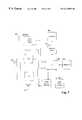
- FIG. 7is a block diagram of a mobile terminal including an auxiliary receiver or an auxiliary receiver and transmitter in accordance with the present invention.
- FIG. 8is a block diagram of a wireless base station including an auxiliary receiver or an auxiliary receiver and transmitter in accordance with the present invention.
- the cellular communication system 100includes a local area network 105 having a system backbone 110 and a plurality of base stations 115 coupled thereto.
- the backbone 110is shown to be a hardwired data communication path made of twisted pair cable, shielded coaxial cable or fiber optic cable, for example.
- the backbone 110could be wireless in nature so as to provide an added dimension of flexibility.
- each base station 115serves as an access point through which wireless communications may occur between devices coupled to the system backbone 110 and one or more mobile terminals 117 included in the system 100 .
- the system 100is a direct sequence, spread spectrum (DSSS) system in which each of the base stations 115 is capable of communicating on any one of a plurality of channels at different respective frequencies.
- DSSSdirect sequence, spread spectrum
- the base station 115will determine whether to initiate a change to another channel found to have less noise.
- the system 100is considered to be frequency agile whereby each base station 115 can selectively choose among a plurality of channels on which to operate.
- the base station 115communicates such information to any mobile terminals 117 which are registered to the base station 115 .
- Each mobile terminal 117is configured to adjust its own parameters accordingly so as to operate on the newly selected channel.
- each base station 115 together with the other devices in the systemare designed to operate in either the 902-928 MHz or 2.4-2.48 GHz bands.
- Such bandsrepresent unlicensed bands provided by the FCC for low power communication devices in the U.S., although operation in other bands is certainly within the scope of the invention.
- Within each bandthere are five predefined channels A through E at different respective frequencies on which DSSS communications can be carried out.
- Each base station 115is capable of selecting any one of the channels A through E on which to communicate as is discussed more fully below.
- communications involving the base stations 115 and mobile terminals 117involve utilizing a predetermined spreading code known as a pseudo noise (PN) sequence to spread the data being transmitted.
- PNpseudo noise
- Data which is receivedis despread according to the same PN sequence.
- each wireless base station 120associates itself, typically by registration, with another base station, whether hardwired or wireless, such that a communication link is formed between itself and other devices situated on the system backbone 110 .
- Each base station 115 , 120is capable of wirelessly communicating with other devices in the system 100 via a respective antenna 125 .
- a geographic cell 127 associated with each base station 115 , 120defines a region, or area of coverage, in which successful wireless communication may occur.
- the cell 127may take one of several different forms and sizes. For example, in the event the antenna 125 is an omni-directional antenna, a generally spherical cell area coverage is obtained. However, a directed yagi-type antenna or other form of antenna could also be used as will be readily appreciated.
- each base station 115also includes an auxiliary antenna 129 .
- the auxiliary antenna 129preferably is of the same type as described above with reference to the antenna 125 and provides equivalent cell coverage 127 .
- the auxiliary antenna 129is coupled to an auxiliary receiver or transceiver included in the base station 115 .
- the auxiliary receiver or transceiveris configured to operate substantially independently of a main transceiver also included in the base station 115 and which is used for carrying out conventional cellular communications.
- the auxiliary receiver or transceiver in combination with the antenna 129allows the base station 115 to scan substantially continuously the noise conditions of any or all of the available communication channels A through E to determine if, and when, the base station 115 may wish to switch from one channel to another. For example, if a base station 115 is currently operating on channel A and the auxiliary receiver determines that noise conditions on channel C are much lower, the base station 115 may initiate a change from channel A to channel C.
- Such configurationhas advantages over prior art systems having only one transceiver and one antenna, in that the base station 115 is able to maintain continuous, uninterrupted communications with the mobile terminals 117 in its cell 127 area even during the scanning process.
- the cellular communication system 100includes one or more mobile terminals 117 .
- Each mobile terminal 117communicates with devices on the system backbone 110 via a selected base station 115 , 120 .
- the mobile terminal 117Upon roaming from one cell 127 to another, the mobile terminal 117 is configured to associate itself with a new base station 115 , 120 .
- FIG. 2represents a block diagram of a given base station 115 within the system 100 .
- the base stationincludes a main transceiver 200 and an auxiliary receiver 201 which are each controlled by a microprocessor 202 .
- the main transceiver 200includes a transmitter 204 and a receiver 206 for respectively transmitting and receiving conventional cellular communications via the antenna 125 .
- the transceiver 200is conventional in design and is capable of operating on any one of five different channels A through E as controlled by the microprocessor 202 . Control signals and data are exchanged between the microprocessor 202 , the transmitter 204 and the receiver 206 by way of a control/data bus 208 connected therebetween. Since the particular design of the main transceiver 200 is generally conventional and is not necessarily germane to the present invention, further detail is omitted.
- the auxiliary receiver 201 as shown in FIG. 2is provided in the base station 115 to scan substantially continuously the channels A through E on which the main transceiver 200 is not currently operating on in order to evaluate noise conditions.
- the auxiliary receiver 201avoids the necessity of the receiver 206 in the main transceiver 200 having to go “off-line” with respect to the mobile terminals 117 in order to evaluate noise conditions on the other available channels as in conventional devices. Consequently, overall system performance is greatly enhanced as will be appreciated.
- the auxiliary receiver 201includes a radio frequency (RF) section 222 and a modulation section 224 .
- RFradio frequency
- the receiver 201is controlled by the microprocessor 202 with respect to the operation of the RF section 222 and the modulation section 224 .
- a memory 228such as a RAM or the like is also included in the receiver 201 and can serve as data storage.
- the memory 228includes a non-volatile portion for storing appropriate operating code to be executed by the microprocessor 202 for carrying out the functions described herein. The manner in which the microprocessor 202 can be programmed to carry out such functions will be readily apparent to those having ordinary skill in the art based on the description provided herein.
- Signals which are received by the auxiliary antenna 129are provided to an RF downconverter circuit 234 included in the RF section 222 .
- the RF downconverter circuit 234is driven by a frequency synthesizer 236 which produces an output frequency on line 238 which is input to the RF downconverter 234 .
- the RF downconverter circuit 234includes a mixer (not shown) which mixes the incoming signals from the antenna 129 down to a corresponding base band signal provided on line 240 .
- the frequency synthesizer 236is controllable by the microprocessor 202 via line 242 in order to control the specific channel on which the receiver 201 receives a signal.
- the microprocessor 202provides control information to the frequency synthesizer 236 which causes the synthesizer to selectively produce an output frequency on line 238 corresponding to the carrier frequency of any of channels A through E. Accordingly, by adjusting the output frequency of the frequency synthesizer 236 the microprocessor 202 can determine whether the receiver 201 receives signals on channel A, B, C, D or E.
- the RF section 222also includes a conventional received signal strength indicator (RSSI) circuit 242 which produces an output on line 244 indicative of the RSSI level of any signals received on a particular channel at a given time.
- RSSIreceived signal strength indicator
- the output of the RSSI circuit 242is provided to the microprocessor 202 which samples the output as described below in order to evaluate the noise conditions of each particular channel A through E.
- the base band signal provided on line 240 from the RF downconverter circuit 240is input to a PN decoder circuit 250 included in the modulation section 224 .
- the PN decoder circuit 250is designed to despread the signal from the RF downconverter circuit 240 according to the particular PN sequence utilized in the system 100 .
- the actual PN sequenceis not critical to the invention, although the PN decoder circuit 250 is designed to include an output on line 252 which is indicative of a degree of correlation between any data in the received signal and the PN sequence.
- the receiver 201receives signals on any given channel (i.e., channels A through E), the receiver 201 receives any noise which may be existent on the particular channel at that time.
- the receiver 201may receive intelligible signals which are being transmitted from the base stations 115 , 120 or mobile terminals within the system 100 and which happen to be operating on that particular channel.
- the output on line 252indicates a strong degree of correlation (correlated) it can be assumed that the received signal represents an intelligible signal and that a device within the system 100 currently is using that particular channel. If the output on line 252 indicates a low degree of correlation (non-correlated), this indicates that the received signal represents unintelligible noise.
- the output on line 252is provided to the microprocessor 202 which utilizes such information in the manner described below to determine which, if any, channel to change to during operation.
- the preferred embodimentutilizes both the RSSI signal and the degree of correlation to determine which channel is best to be operating on, it should be appreciated that alternative embodiments may only use one or the other but not both.
- the despread data which is output from the PN decoder 250is provided to the input of demodulator circuit 251 which is designed to carry out on the received signal whatever particular type of demodulation utilized in the system 100 .
- demodulator circuit 251is designed to demodulate the received signal according to BPSK techniques.
- BPSKbinary phase shift keying
- the output of the demodulator 251is provided to a symbol to data converter 253 which performs symbol to data conversion in accordance with the communication parameters of the system 100 .
- the output of the symbol-to-data converter 253 on line 254represents any system data which may have been included in the received signal.
- Such datais coupled to the microprocessor 202 where it is evaluated for content if desired.
- the base station 115 in this embodimentincludes a single microprocessor 202 which operates at a sufficiently high rate to control both the main transceiver 200 and the auxiliary receiver 201 substantially simultaneously (e.g., via multitasking).
- the transceiver 200 and receiver 201could each have their own dedicated microprocessor for providing control. Information between the dedicated microprocessors can then be exchanged in order to control which particular channel the respective devices operate on.
- the base station 115is connected to the system backbone 110 via a connector 256 .
- the connector 256is connected to the backbone 110 at one end and to a network adapter transceiver 258 included in the base station 115 at the other end.
- the network adapter transceiver 258is configured according to conventional network adapter transceiver techniques to allow the base station 115 to communicate over the network.
- the network adapter transceiveris coupled to the microprocessor 202 via line 260 . Information received via the backbone 110 can be transmitted via the main transceiver 200 and vice versa.
- FIG. 3represents a table 264 maintained by the processor 202 in the memory 228 .
- the table 264contains noise condition information for each of the available channels A through E in the system 100 .
- the microprocessor 202is programmed to cause the auxiliary receiver 201 to scan continuously through each of the channels A through E sampling the noise conditions on each of the channels on which the transceiver 200 is not operating.
- the auxiliary receiver 201is controlled so as to receive incoming signals according to the sequence B, C, D, E, B, C, . . . , etc. assuming, for example, the transceiver 200 is operating on channel A.
- the microprocessor 202is programmed to sample the RSSI signal on line 244 and the correlation output on line 252 for a sample time period of Tsample.
- the period Tsampleis preselected so as to be at least as long as the maximum time interval between any beacons which are transmitted by a given base station 115 , 120 within the system.
- base stations 115 , 120 in a passive scanning systembroadcast beacons periodically which enable mobile terminals 117 to lock on to a base station and register therewith.
- the period Tsampleis one second, although other time periods are certainly possible.
- the information obtained via the auxiliary receiver 201 from the RSSI level and correlation output samples from each channelis then maintained in the table 264 . Further, the main transceiver 200 under the control of the microprocessor 202 periodically samples the RSSI level and correlation degree of the current channel on which the main transceiver 200 is operating. Such information is obtained by the receiver 206 in the same manner as done by the auxiliary receiver 201 with respect to the channels which the main transceiver 200 is not currently working on. This avoids the auxiliary receiver 201 having to spend time sampling noise conditions on the channel the main transceiver 200 is currently operating on; and since the main transceiver 200 already is on the current channel, there is no need for the main transceiver 200 to go “off-line” and change to another channel. Nevertheless, in another embodiment the auxiliary receiver 201 is responsible for obtaining the noise condition information with respect to all of the available channels.
- the noise condition information obtained by the auxiliary receiver 201 for the other available channels and by the main receiver 206 for the current channelis provided to the microprocessor 202 which processes and stores the information in the table 264 .
- the table 264includes five different rows corresponding to channels A through E, respectively.
- the table 264includes information relating to the noise level thereof as determined by the RSSI level and correlation output from the PN decoder.
- the tableincludes the average RSSI level (e.g., in decibels) for the corresponding channel during the most recent sample period Tsample.
- the average RSSI level as stored in column 266is calculated by the microprocessor 202 only for such times during the time period Tsample that the correlation output on line 252 does not exceed a predetermined threshold (i.e., is considered non-correlated).
- Column 268includes the average RSSI level as calculated by the microprocessor 202 during the most recent sample period Tsample, but in this case only for such times during the sample that the correlation output on line 252 is equal to or exceeds the predetermined threshold (i.e., is considered correlated).
- Such existence of a correlated signalis considered herein to be indicative of a use condition of a channel whereby the channel is actually in use by a device.
- the table 264also includes an average of the RSSI levels for both non-correlated and correlated signals over a predetermined number of most recent samples.
- column 270 in the table 264contains the average RSSI level over the five most recent samples of the respective channel as computed by the microprocessor 202 during such times when the correlation output on line 252 indicates a non-correlated signal.
- column 272contains the average RSSI level over the five most recent samples of the respective channel as computed by the microprocessor 202 during such times when the correlation output on line 252 indicates a correlated signal.
- the table 264also includes a column 274 which includes a flag for indicating whether a beacon was received during the most recent sample of the respective channel.
- a flag for indicating whether a beacon was received during the most recent sample of the respective channelAs discussed above in relation to FIG. 2, in the event an intelligible signal is received by the auxiliary receiver 201 , such signal is demodulated, decoded and converted in the modulation section 224 . The information in the received signal is then provided to the microprocessor 202 via line 254 . The microprocessor 202 is programmed to analyze the information received on line 254 to determine whether the received signal includes a beacon which was sent from another base station 115 , 120 in the system 100 . Such determination is based on conventional techniques including analyzing the appropriate data fields contained in the information provided on line 254 .
- a beaconis received on a particular channel during a time Tsample, this indicates that a base station 115 , 120 within the system 100 is currently operating on the particular channel and is within the cell coverage of the present base station 115 . Since it is desirable to avoid two or more base stations using the same channel within range of each other, a flag is set in column 274 to indicate whether a beacon has been received in the most recent sample. It is noted that such information is maintained only for the most recent sample since there is the possibility that the base station from which a previous beacon originated may itself have changed to another channel.
- FIG. 4is a flowchart representing the operation of the base station 115 with respect to monitoring the noise conditions of the available channels via the auxiliary receiver 201 and changing channels based thereon.
- Step 300represents startup of the base station 115 in response to being powered up via an on/off switch or the like.
- the base station 115under the control of the microprocessor 202 carries out a self-initialization routine as is conventional.
- the main transceiver 200selects a default channel (e.g., channel A) on which to operate.
- the main transceiver 200may not select a default channel but rather may immediately perform a scan as discussed below to select on which channel to begin operations.
- the microprocessor 202proceeds to step 302 in which the auxiliary receiver 201 is utilized to obtain a sample of the RSSI level on line 244 and the correlation output on line 252 for each channel. Specifically, if the main transceiver 200 is currently operating on channel A the microprocessor 202 controls the output frequency of the frequency synthesizer 236 such that a sample can be obtained by the auxiliary receiver 201 for each of channels B, C, D and E. The microprocessor 202 computes the average RSSI level for each sample for both the non-correlated and correlated signals and stores such information for each channel in the table 264 (FIG. 3) in columns 266 and 268 , respectively.
- the table 264FIG. 3
- the microprocessor 202 in step 302computes the average RSSI levels for the non-correlated and correlated signals over past five samples for each channel and stores such information in columns 270 and 272 , respectively.
- identical information for channel A on which the transceiver 200 is currently operating onis obtained by the main receiver 206 and is also stored in the table 264 .
- the average RSSI levelsare computed based on the actual RSSI samples and a remaining number of phantom samples set to equal a total of five. Each phantom sample has an average RSSI level of zero, for example.
- the microprocessor 202 in step 302determines if a beacon was received on any of the channels during the samples taken in step 302 . If yes, the microprocessor 202 sets a flag in column 274 indicating the same. If no, the microprocessor 202 resets a flag in column 274 so as to indicate such fact.
- the microprocessor 202then proceeds from step 302 to step 304 in which the microprocessor 202 determines whether at least five RSSI samples have been acquired for each channel. If no, the microprocessor 202 proceeds to step 306 in which the base station 115 pauses before returning to step 302 to obtain another RSSI sample from each channel A through E.
- the duration of the pause in step 306can be anywhere from zero to several seconds, for example, depending on how often it is desired that the auxiliary receiver 201 update the noise condition information. In the exemplary embodiment, the microprocessor 202 pauses for five seconds in step 306 before returning to step 302 .
- step 304the microprocessor 202 determines that at least five samples have been obtained for each of the channels A through E, the microprocessor 202 proceeds to step 308 .
- step 308the microprocessor 202 is programmed to determine whether the noise conditions for the channel on which the main transceiver 200 is currently operating exceed a predetermined threshold level. More specifically, in step 308 the microprocessor 202 looks to the information in column 270 of table 264 to determine if the average RSSI level for non-correlated signals over the last five samples exceeds a predetermined threshold indicating noisy conditions. If the main transceiver 200 is currently operating on channel A, the microprocessor 202 will look to column 270 in relation to channel A.
- the microprocessor 202compares the information for that particular channel with the predetermined threshold. If the noise conditions are above the threshold then it is assumed that the current channel is too noisy to maintain reliable communications and therefore the microprocessor 202 should attempt to identify another channel on which the base station 115 can operate.
- step 308the microprocessor 202 does not consider the information in column 272 pertaining to the RSSI signal level for correlated signals. Since the main transceiver 201 is operating simultaneously with the steps shown in FIG. 4, the main transceiver 201 and/or mobile terminals registered thereto is likely to be actively involved in communications on the current channel at such times when the RSSI levels are sampled for that particular channel. Hence, the RSSI levels during the correlated signals are not likely to represent noise or activities of another base station, but rather are likely to be indicative of operations of the base station itself.
- step 308the microprocessor 202 determines that the average RSSI level in column 270 does not exceed the predetermined threshold so as to indicate a low-noise condition
- the microprocessor 202proceeds to step 310 .
- step 310the microprocessor 202 determines whether any of the other available channels exhibit even better noise conditions (i.e., less noise). More specifically, the microprocessor 202 looks to the average RSSI levels over the last five samples as reflected in column 270 of table 264 for each of the channels other than the channel on which the main transceiver 200 is currently operating on. The microprocessor 202 determines whether the average RSSI level in column 270 is more than a predetermined amount less than that of the current channel.
- the microprocessor 202determines if any of the other channels have an average RSSI level in column 270 which is more than 10 db less than that of the current channel. If no, it is assumed that the main transceiver 200 is currently on the optimum channel and the microprocessor 202 proceeds to step 312 . In step 312 the base station 115 pauses in the same manner described above with respect to step 306 prior to returning to step 302 in order to reevaluate the noise conditions on each channel.
- step 310determines that the noise conditions on another channel are significantly better, the microprocessor 202 proceeds to step 314 in which a new channel is selected according to a predefined selection criteria. Similarly, if in step 308 the microprocessor 202 determines that the noise conditions on the current operating channel of the main transceiver 200 exceed the predetermined threshold, the microprocessor 202 proceeds to step 314 . In step 314 the microprocessor 202 carries out the following predefined selection criteria for selecting a new channel on which the main transceiver 200 is to operate:
- the predetermined selection criteria in step 314is utilized by the microprocessor 202 to select a new channel on which the main transceiver 200 can operate.
- the particular criteria applied in step 314can be modified to include different parameters, weighting of various criteria, etc., and the criteria explained above is intended merely to be exemplary.
- the same channel on which the main transceiver 200 is currently operating onmay be selected in step 314 as the new channel in the event the current channel continues to exhibit the best operating conditions as far as the channels available.
- step 316the microprocessor 202 provides control information on line 208 which causes the main transceiver 200 to broadcast information on the current channel informing each of the mobile terminals 117 and wireless base stations 120 registered to the base station 115 of an upcoming channel change. Specifically, the main transceiver 200 broadcasts an information packet indicating to the mobile terminals 117 and wireless base stations which particular channel the base station 115 will be changing to and at what time such change will occur.
- a protocol for implementing such a channel change routinemay be based on the type described in U.S. Pat. No. 5,142,550, although other protocols are certainly within the intended scope of the invention.
- step 316the microprocessor 202 proceeds to step 318 in which it causes the main transceiver 200 to switch to the newly selected channel at the time noted in the information broadcast in step 316 . Thereafter, the microprocessor 202 proceeds to step 312 and then back to step 302 as the main transceiver 200 continues to operate on the new channel. The above procedure is then repeated.
- step 314In the event that the newly selected channel in step 314 ends up being the same channel as which the main transceiver 200 was currently operating on, there is no need for the microprocessor 202 to carry out steps 316 and 318 .
- the microprocessor 202is programmed to detect in step 314 whether the new channel is the same as the current channel. If so, the microprocessor 202 bypasses steps 316 and 318 and proceeds directly to step 312 (not shown).
- the process for evaluating the noise conditions of the various channels and instructing the main transceiver 200 to change channels as represented in FIG. 4is carried out while the main transceiver 200 carries out normal operations. In other words, it is not necessary for the main transceiver 200 to go “off-line” as in the past so as to evaluate the noise conditions on other channels. Consequently, system performance is increased in the present invention.
- auxiliary transmitter 350is added to the base station 115 in addition to the auxiliary receiver 201 so as to form an auxiliary transceiver 352 .
- the construction and operation of the main transceiver 200 and the auxiliary receiver 201are substantially identical to the embodiment of FIG. 2 . Consequently, only the relevant differences will be discussed herein.
- the auxiliary transmitter 350provides the base station 115 with the ability to continue to communicate with any mobile terminals 117 or wireless base stations 120 which may have missed a broadcast message to change channels.
- the mobile terminals 117 and wireless base stationstypically are designed to start searching for another base station and/or channel upon realizing that the base station to which they were previously registered is no longer available (e.g., has changed to a different channel unbeknownst to the mobile terminal), the auxiliary transmitter 350 is used to actively seek out such mobile terminals and/or wireless base stations.
- the auxiliary transceiver 350is used to rebroadcast information to any remaining mobile terminals and/or wireless base stations informing them to change channels as is discussed more fully below.
- the auxiliary transmitter 350includes a data-to-symbol converter 354 which receives binary information to be transmitted from the microprocessor 202 via line 356 .
- the data-to-symbol converter 354converts the data from the microprocessor 202 into symbol data by performing a conversion inverse to that performed by the symbol-to-data converter 253 in the auxiliary receiver 201 .
- the symbol data from the data-to-symbol converter 354is then modulated by a modulator 356 which modulates the data based on the same modulation technique employed by the demodulator 251 in the auxiliary receiver 201 .
- the modulated datais then encoded or spread by a PN encoder 358 using the same PN sequence employed by the PN decoder 250 discussed above.
- the output of the PN encoder 358is provided to an RF upconverter circuit 360 which mixes the modulated signal onto an RF carrier as determined by the microprocessor 202 . More specifically, the RF upconverter circuit 360 is driven by the frequency synthesizer 236 in the same manner as the RF downconverter circuit 234 in order to transmit the modulated information selectively on either channel A, B, C, D or E. By providing a control signal on line 242 , the microprocessor 202 causes the transceiver 352 to transmit and receive signals on a selected channel.
- the RF upconverter circuit 360includes a mixer (not shown) which mixes the modulated signal from the modulator 358 onto a carrier frequency provided by the frequency synthesizer 236 .
- the carrier frequencyis the same frequency provided to the RF downconverter 234 which allows signals to be received on the same channel.
- the modulated RF signal which is output from the RF upconverter circuit 360is coupled to the transmit terminal of an antenna switch 362 .
- the receive terminal of the antenna switch 362is coupled to the input of the RF downconverter 234 .
- the antenna 129is coupled to the antenna terminal of the antenna switch 362 .
- the position of the antenna switch 362is controlled by the microprocessor 202 via a line 364 .
- the antenna switch 362is in a receive position, the antenna 129 is coupled to the input of the RF downconverter circuit 234 so that signals may be received via the antenna 129 and the auxiliary receiver 201 .
- the antenna switch 362is in a transmit position, the antenna 129 is coupled to the output of the RF upconverter circuit 360 so that signals may be transmitted via the antenna 129 and the auxiliary transmitter.
- FIG. 6is a flowchart representing the operation of the base station 115 according to the embodiment of FIG. 5 with respect to monitoring the noise conditions on all of the available channels. Steps 300 through 318 in FIG. 6 are identical to those described above in relation to the flowchart of FIG. 4 . Such steps are carried out in the embodiment of FIG. 5 while the microprocessor 202 causes the antenna switch 362 to be in the receive position so that the noise conditions of the various channels can be evaluated. Following step 318 , however, the microprocessor 202 in the embodiment of FIG. 5 proceeds to step 370 . In step 370 , the microprocessor 202 initially switches the antenna switch 362 to the transmit position.
- the microprocessor 202causes the auxiliary transmitter 350 to broadcast a probe on the same channel which the main transceiver 200 had been communicating on immediately prior to changing channels in step 318 .
- the probecontains information which prompts any mobile terminals 117 and/or wireless base stations 120 which may be searching for a base station 115 with which to register to respond by transmitting a response to the probe on the same channel.
- the microprocessor 202switches the antenna switch 326 to the receive position and begins “listening” for whether a response to the probe or any other activity is received via the receiver 201 to determine if any devices remain on the channel.
- the microprocessor 202determines in step 372 if a probe response or any other activity is received via the auxiliary receiver 201 .
- a probe responsein particular can be detected by the microprocessor 202 based on the content of any received signal as provided on line 254 . Additionally, however, other activity on the channel can be detected simply by way of the correlation output on line 252 . If the output on line 252 exhibits a degree of correlation which exceeds a predetermined threshold (e.g., is considered correlated), the received signal is considered to represent activity on the channel as opposed to random noise.
- step 374determines if a predetermined amount of time has passed since the main transceiver 200 first switched to a new channel in step 318 .
- a predetermined amount of timeis selected to be of sufficient duration to assume that any devices not responding to a probe during such period have now changed over to the new channel selected in step 314 .
- the predetermined amount of time in step 374may be equal to the maximum amount of time required for a mobile terminal or wireless base station within the system to begin scanning on its own and identify a new base station and/or channel with which to register. The mobile terminal or wireless base station typically will begin to scan for such new base station and/or channel upon realizing that the transmissions of the mobile terminal or wireless base station are no longer being acknowledged by the previous base station.
- step 374If in step 374 the predetermined amount of time has not expired, the microprocessor 202 returns to step 370 in which the auxiliary transceiver 352 again broadcasts a probe and listens for a response or any other activity on the previous channel. If in step 374 the predetermined amount of time has passed, the microprocessor 202 assumes that no devices remain unregistered following the channel change. Consequently, the microprocessor 202 returns to step 302 .
- step 372the microprocessor 202 proceeds to step 376 in which the microprocessor 202 causes the auxiliary transceiver 350 to rebroadcast the channel change information on the previous channel. Specifically, the microprocessor 202 switches the antenna switch 362 to the transmit position and causes the auxiliary transmitter 350 to broadcast again the information alerting any mobile terminals and wireless base stations of the change in channel of the main transceiver 200 .
- step 376returns the antenna switch 362 to the receive position and begins again to listen for a response or any other activity via the auxiliary receiver 201 .
- step 376the microprocessor 202 returns to step 374 .
- the embodiment of FIG. 5provides for the auxiliary transceiver 352 to monitor noise conditions while the main transceiver 200 carries out normal communications.
- the auxiliary receiver 201evaluates the noise conditions of the available channels, and the auxiliary transmitter 350 is utilized to contact any devices which may have inadvertently missed a channel change. As a result, channel changes may be carried out smoothly without the necessity of the main transceiver 200 having to go off-line temporarily.
- further enhancementsmay be added wherein the auxiliary transmitter 350 transmits test packets to base stations which respond with an indication of how well the base station was able to receive the transmitted packet. With this information the mobile device may better analyze operating conditions on a particular channel from both the mobile's position and the base station's position.
- the present inventionhas been described above as it relates to the provision of an auxiliary receiver or transceiver in a base station.
- the inventioncan be implemented in a mobile terminal or a wireless base station as well.
- a noise condition assessmentis done by the auxiliary receiver or transceiver in a mobile terminal 117 or wireless base station 120 .
- the information regarding whether a less noisy channel existsis transmitted from the mobile terminal 117 or wireless base station 120 to the base station 115 which is notified by the mobile terminal or wireless base station when and to which channel to switch.
- the base station 115then broadcasts such information to any other mobile terminals and wireless base stations registered thereto so that all of the devices know when to change channels.
- FIG. 7is a block diagram of a mobile terminal 117 in accordance with the invention.
- the mobile terminal 117like either of the base station embodiments in FIGS. 2 and 5, includes an auxiliary receiver 201 or transceiver 352 , a main transceiver 200 , a microprocessor 202 and a memory 228 .
- the mobile terminal 117includes a display 400 driven by a display driver 402 which is coupled to the microprocessor 202 .
- the display 400is utilized by the mobile terminal 117 to display data which is received by or input into the mobile terminal 117 as is conventional.
- the mobile terminal 117also includes a user input device 404 such as a keypad or the like for allowing a user to input data and/or commands.
- the mobile terminal 117includes a bar code reader 406 which allows the user to input information via a bar code.
- step 316instead involves the mobile terminal 117 transmitting the channel change information and timing to the base station 115 to which it is registered.
- the main transceiver 200is free to carry on conventional mobile terminal communications within the system.
- FIG. 8shows an embodiment of a wireless base station 120 incorporating an auxiliary receiver 201 or transceiver 352 .
- the construction of the wireless base station 120is substantially identical to that of the base station 115 with the exception that the wireless base station 120 is not coupled to the system backbone 110 . Instead, the wireless base station 120 serves as an intermediary with respect to communications between the mobile terminals 117 and the base stations 115 .
- the operation of the wireless base station 120 with respect to evaluating noise conditionsis substantially identical to the procedures described above in relation to FIG. 4 or 6 . However, with respect to the operation as described in FIGS. 4 and 6, step 316 would be eliminated and upon deciding to change channels, the wireless base station 120 would simply register with a new base station which would in turn inform all other base stations of the new association, as is conventional.
- a benefitis gained in that the communication link between the base stations and other devices need not be broken or interrupted so that an assessment of other potential channels to switch to can take place.
- the auxiliary receiver/transceiver and the main transceiverare described above as utilizing separate antennas. However, in another embodiment the same antenna may be shared by both. Furthermore, additional steps may be taken when evaluating the noise conditions. For example, immediately prior to the main transceiver 200 broadcasting the channel change notice in step 316 as shown in FIG. 4, the auxiliary receiver 201 may sample the noise conditions on the new channel one last time to ensure that conditions have not changed since last sampling the channel and determining that the channel provides the optimum conditions. Further, in order to better avoid problems associated with intermodulation, the auxiliary receiver/transceiver 201 / 352 may be configured to only take RSSI samples when the main transceiver 200 is not transmitting information.
- the microprocessor 202is programmed to ascertain the data rate of the received signal based on the correlation output on line 252 .
- the data rate between mobile terminals and base stationsis increased in some systems in the event the mobile terminals and base stations are in close physical proximity and share a strong signal.
- This data rate informationis stored for each respective channel in the table 264 and is used as part of the predetermined selection criteria performed in step 314 in order to select a new channel.
- the microprocessor 202is programmed to give preference to other channels not exhibiting such a high data rate. This helps to avoid two base stations operating on the same channel in relatively close physical proximity.
- the present inventionis not limited to a frequency agile DSSS system.
- the inventionis useful in any system wherein a base station and a mobile terminal can communicate on two or more different communication channels.
- changes between channelscan also be based primarily on the amount of use of the other channels.
- the auxiliary receiverdetermines which channel involves the least use as determined by the amount of time during each sample that a correlated signal is received as determined by the correlated output on line 252 .
Landscapes
- Engineering & Computer Science (AREA)
- Computer Networks & Wireless Communication (AREA)
- Signal Processing (AREA)
- Mobile Radio Communication Systems (AREA)
Abstract
Description
Claims (38)
Priority Applications (2)
| Application Number | Priority Date | Filing Date | Title |
|---|---|---|---|
| US08/672,426US6215982B1 (en) | 1996-06-28 | 1996-06-28 | Wireless communication method and device with auxiliary receiver for selecting different channels |
| US08/715,868US6047175A (en) | 1996-06-28 | 1996-09-19 | Wireless communication method and device with auxiliary receiver for selecting different channels |
Applications Claiming Priority (1)
| Application Number | Priority Date | Filing Date | Title |
|---|---|---|---|
| US08/672,426US6215982B1 (en) | 1996-06-28 | 1996-06-28 | Wireless communication method and device with auxiliary receiver for selecting different channels |
Related Child Applications (1)
| Application Number | Title | Priority Date | Filing Date |
|---|---|---|---|
| US08/715,868Continuation-In-PartUS6047175A (en) | 1996-06-28 | 1996-09-19 | Wireless communication method and device with auxiliary receiver for selecting different channels |
Publications (1)
| Publication Number | Publication Date |
|---|---|
| US6215982B1true US6215982B1 (en) | 2001-04-10 |
Family
ID=24698499
Family Applications (1)
| Application Number | Title | Priority Date | Filing Date |
|---|---|---|---|
| US08/672,426Expired - LifetimeUS6215982B1 (en) | 1996-06-28 | 1996-06-28 | Wireless communication method and device with auxiliary receiver for selecting different channels |
Country Status (1)
| Country | Link |
|---|---|
| US (1) | US6215982B1 (en) |
Cited By (53)
| Publication number | Priority date | Publication date | Assignee | Title |
|---|---|---|---|---|
| US6393261B1 (en)* | 1998-05-05 | 2002-05-21 | Telxon Corporation | Multi-communication access point |
| US20020097681A1 (en)* | 2001-01-25 | 2002-07-25 | Bijan Treister | Approach for managing communications channels based on performance |
| US6477372B1 (en)* | 2000-11-06 | 2002-11-05 | Motorola, Inc. | Method for a radiotelephone to scan for alternate radiotelephone systems |
| US20020173336A1 (en)* | 2001-04-12 | 2002-11-21 | Ranta Pekka A. | Method for increasing data transmission rate, and receiver, transmitter and terminal |
| US20020181418A1 (en)* | 2001-05-08 | 2002-12-05 | Awater Geert Arnout | Network system comprising access points |
| US20030011500A1 (en)* | 1997-09-02 | 2003-01-16 | Kabushiki Kaisha Toshiba | Noise suppression circuit, asic, navigation apparatus, communication circuit, and communication apparatus having the same |
| US20030035410A1 (en)* | 2001-08-14 | 2003-02-20 | Rajiv Laroia | Methods and apparatus for wireless network connectivity |
| US6539227B1 (en)* | 1998-12-18 | 2003-03-25 | Telefonaktiebolaget Lm Ericsson (Publ) | Methods and systems for controlling hard and soft handoffs in radio communications systems |
| US20030064752A1 (en)* | 2001-09-28 | 2003-04-03 | Tomoko Adachi | Base station apparatus and terminal apparatus |
| US20030136042A1 (en)* | 2000-02-16 | 2003-07-24 | Luciano Albanesi | Electromechanical safety for weapons, and weapon provided with the same |
| US20030211862A1 (en)* | 2002-05-13 | 2003-11-13 | Hutchison James A. | Subscriber station with dynamic multi-mode service acquisition capability |
| US20030231621A1 (en)* | 1998-09-11 | 2003-12-18 | Cirrus Logic, Inc. | Dynamic communication channel switching for computer networks |
| WO2004019506A1 (en)* | 2002-08-20 | 2004-03-04 | Via Technologies, Inc. | Pcd with transmitted rf power strength indicator and warning system |
| WO2004034600A1 (en)* | 2002-10-11 | 2004-04-22 | Widefi, Inc. | Reducing loop effects in a wireless local area network repeater |
| US20040087344A1 (en)* | 2002-11-01 | 2004-05-06 | Parra Fidol Joaquin | Wireless LAN base station device having antennas and transmission-reception portion |
| US6751461B1 (en)* | 2000-11-20 | 2004-06-15 | Motorola, Inc. | Apparatus and method for operating a communication unit using a default channel |
| US20040114546A1 (en)* | 2002-09-17 | 2004-06-17 | Nambirajan Seshadri | System and method for providing a mesh network using a plurality of wireless access points (WAPs) |
| US20040209626A1 (en)* | 2003-04-18 | 2004-10-21 | Fitzrandolph David K. | Method and device for detecting an interference condition |
| US20040229659A1 (en)* | 2003-05-15 | 2004-11-18 | Boos John P. | Current reduction in a communication device |
| WO2005055461A1 (en)* | 2003-12-04 | 2005-06-16 | Via Technologies Inc. | Personal communication device with transmitted rf power strength indicator |
| US20050153702A1 (en)* | 2004-01-08 | 2005-07-14 | Interdigital Technology Corporation | Radio resource management in wireless local area networks |
| US20060025127A1 (en)* | 2004-07-27 | 2006-02-02 | International Business Machines Corporation | Forced roaming to avoid interference |
| US20060056352A1 (en)* | 2002-11-15 | 2006-03-16 | Widefi, Inc. | Wireless local area network repeater with detection |
| US20060063485A1 (en)* | 2002-10-15 | 2006-03-23 | Gainey Kenneth M | Wireless local area network repeater with automatic gain control for extending network coverage |
| US20060063484A1 (en)* | 2002-10-24 | 2006-03-23 | Proctor James A Jr | Wireless local area network repeater with in-band control channel |
| US20060098592A1 (en)* | 2002-12-16 | 2006-05-11 | Widefi, Inc. | Wireless network repeater |
| US20060168633A1 (en)* | 2005-01-27 | 2006-07-27 | Lg Electronics Inc. | Broadcasting terminal and viewing method |
| US20060193271A1 (en)* | 2005-01-28 | 2006-08-31 | Widefi, Inc. | Physical layer repeater configuration for increasing MIMO performance |
| US20070025486A1 (en)* | 2002-10-01 | 2007-02-01 | Widefi, Inc. | Control message management in physical layer repeater |
| US20070032192A1 (en)* | 2004-06-03 | 2007-02-08 | Widefi, Inc. | Frequency translating repeater with low cost high performance local oscillator architecture |
| CN1957624A (en)* | 2004-01-08 | 2007-05-02 | 美商内数位科技公司 | Radio resource management in wireless local area networks |
| US20070109980A1 (en)* | 2000-05-19 | 2007-05-17 | Awater Geert A | Wireless LAN with load balancing |
| US20070147253A1 (en)* | 2004-12-22 | 2007-06-28 | Arak Sutivong | Efficient ACK to NACK error detection |
| US20080046135A1 (en)* | 2006-07-26 | 2008-02-21 | Farrow Daniel W | Communication control method for a vehicle |
| US20090122837A1 (en)* | 2001-01-25 | 2009-05-14 | Hongbing Gan | Approach For Managing The Use Of Communications Channels Based On Performance |
| US7542769B1 (en)* | 2003-06-30 | 2009-06-02 | Nortel Networks Limited | Dynamic control of eighth-rate gating of the reverse link fundamental channel in a wireless communication system |
| US20090290526A1 (en)* | 2006-09-21 | 2009-11-26 | Qualcomm Incorporated | Method and apparatus for mitigating oscillation between repeaters |
| US20100002620A1 (en)* | 2006-09-01 | 2010-01-07 | Qualcomm Incorporated | Repeater having dual receiver or transmitter antenna configuration with adaptation for increased isolation |
| US20110222617A1 (en)* | 2002-07-05 | 2011-09-15 | Interdigital Technology Corporation | Method for performing wireless switching |
| US8023885B2 (en) | 2004-05-13 | 2011-09-20 | Qualcomm Incorporated | Non-frequency translating repeater with downlink detection for uplink and downlink synchronization |
| US8027642B2 (en) | 2004-04-06 | 2011-09-27 | Qualcomm Incorporated | Transmission canceller for wireless local area network |
| US8064836B1 (en)* | 2008-04-11 | 2011-11-22 | University Of South Florida | Cognitive radio transceiver for dispersed spectrum utilization |
| US8078100B2 (en) | 2002-10-15 | 2011-12-13 | Qualcomm Incorporated | Physical layer repeater with discrete time filter for all-digital detection and delay generation |
| US8089913B2 (en) | 2002-10-24 | 2012-01-03 | Qualcomm Incorporated | Physical layer repeater with selective use of higher layer functions based on network operating conditions |
| US8498234B2 (en) | 2002-06-21 | 2013-07-30 | Qualcomm Incorporated | Wireless local area network repeater |
| EP2103002A4 (en)* | 2006-12-13 | 2014-04-09 | Powerwave Technologies Inc | Time division duplex forward-to-reverse transition signal generator |
| US8774079B2 (en) | 2006-10-26 | 2014-07-08 | Qualcomm Incorporated | Repeater techniques for multiple input multiple output utilizing beam formers |
| US9060352B2 (en) | 2012-08-14 | 2015-06-16 | Cisco Technology, Inc. | Dynamic channel assignment for WLAN deployments with IEEE 802.11ac access points |
| US9125214B2 (en) | 2012-09-04 | 2015-09-01 | Cisco Technology, Inc. | Dynamic enabling of wider channel transmissions with radio monitoring |
| US9223009B1 (en)* | 2011-12-19 | 2015-12-29 | Lockheed Martin Corporation | Method and system for electromagnetic interference (EMI) mitigation using an auxiliary receiver |
| US20150381737A1 (en)* | 2014-06-30 | 2015-12-31 | Davra Networks Limited | Gateway device and a gateway system for an internet-of-things environment |
| US20200077406A1 (en)* | 2017-10-24 | 2020-03-05 | Charter Communications Operating, Llc | Wireless channel allocation amongst multiple base stations |
| US20230073586A1 (en)* | 2021-07-07 | 2023-03-09 | ShadowTech Labs | Apparatus, system, and method for active channel switching and spectrum identification in hostile radio frequency environments |
Citations (26)
| Publication number | Priority date | Publication date | Assignee | Title |
|---|---|---|---|---|
| US4216432A (en)* | 1977-09-08 | 1980-08-05 | General Research Of Electronics, Inc. | Automatic switching system for a combination transceiver-auxilliary receiver radio |
| US4792984A (en)* | 1985-01-31 | 1988-12-20 | Nec Corporation | Radio channel control method for mobile communication system |
| US5101501A (en)* | 1989-11-07 | 1992-03-31 | Qualcomm Incorporated | Method and system for providing a soft handoff in communications in a cdma cellular telephone system |
| US5142550A (en) | 1989-06-29 | 1992-08-25 | Symbol Technologies, Inc. | Packet data communication system |
| US5230082A (en) | 1990-08-16 | 1993-07-20 | Telefonaktiebolaget L M Ericsson | Method and apparatus for enhancing signalling reliability in a cellular mobile radio telephone system |
| US5267262A (en) | 1989-11-07 | 1993-11-30 | Qualcomm Incorporated | Transmitter power control system |
| US5287384A (en) | 1992-10-15 | 1994-02-15 | Lxe Inc. | Frequency hopping spread spectrum data communications system |
| US5361399A (en) | 1992-06-02 | 1994-11-01 | Pagemart, Inc. | Adaptive communication system for transmitting between base stations and portable transceivers via different data rate communication links |
| US5375259A (en)* | 1992-02-20 | 1994-12-20 | Lee; Denny L. Y. | Analog signal noise reduction process and apparatus |
| US5390366A (en) | 1991-03-12 | 1995-02-14 | Nec Corporation | Mobile communication system |
| US5442627A (en)* | 1993-06-24 | 1995-08-15 | Qualcomm Incorporated | Noncoherent receiver employing a dual-maxima metric generation process |
| US5452471A (en)* | 1992-11-12 | 1995-09-19 | Motorola, Inc. | Network of hierarchical communication systems and method therefor |
| US5475864A (en)* | 1993-07-19 | 1995-12-12 | Nec Corporation | High-cross correlation dynamic channel assignment for sectorized cells |
| US5483666A (en)* | 1991-10-21 | 1996-01-09 | Matsushita Electric Industrial Co., Ltd. | Method for allocating channels in a microcellular system |
| US5506867A (en)* | 1991-09-24 | 1996-04-09 | Motorola, Inc. | Cellular radio system using common radio backbone |
| US5539923A (en) | 1993-03-26 | 1996-07-23 | Mitsubishi Denki Kabushiki Kaisha | Wireless mobile telephone system with zone selection control |
| US5546397A (en) | 1993-12-20 | 1996-08-13 | Norand Corporation | High reliability access point for wireless local area network |
| US5594949A (en)* | 1993-02-05 | 1997-01-14 | Telefonaktiebolaget Lm Ericsson | Mobile assisted channel allocation |
| US5640414A (en) | 1992-03-05 | 1997-06-17 | Qualcomm Incorporated | Mobile station assisted soft handoff in a CDMA cellular communications system |
| US5697055A (en) | 1994-10-16 | 1997-12-09 | Qualcomm Incorporated | Method and apparatus for handoff between different cellular communications systems |
| US5701590A (en)* | 1994-07-08 | 1997-12-23 | Nec Corporation | Radio communication system for performing multi-channel access |
| US5794145A (en)* | 1996-06-07 | 1998-08-11 | Telxon Corporation | Mobile device multiband antenna system |
| US5822686A (en)* | 1995-12-11 | 1998-10-13 | Telefonaktiebolaget Lm Ericsson | Channel scanning scheme for signal strength measurement systems and methods |
| US5825764A (en) | 1995-04-13 | 1998-10-20 | Alcatel Nv | TDMA base station arrangement |
| US5940452A (en)* | 1995-11-29 | 1999-08-17 | Motorola, Inc. | Dual mode radio subscriber unit having a diversity receiver apparatus and method therefor |
| US6047175A (en)* | 1996-06-28 | 2000-04-04 | Aironet Wireless Communications, Inc. | Wireless communication method and device with auxiliary receiver for selecting different channels |
- 1996
- 1996-06-28USUS08/672,426patent/US6215982B1/ennot_activeExpired - Lifetime
Patent Citations (27)
| Publication number | Priority date | Publication date | Assignee | Title |
|---|---|---|---|---|
| US4216432A (en)* | 1977-09-08 | 1980-08-05 | General Research Of Electronics, Inc. | Automatic switching system for a combination transceiver-auxilliary receiver radio |
| US4792984A (en)* | 1985-01-31 | 1988-12-20 | Nec Corporation | Radio channel control method for mobile communication system |
| US5142550A (en) | 1989-06-29 | 1992-08-25 | Symbol Technologies, Inc. | Packet data communication system |
| US5101501A (en)* | 1989-11-07 | 1992-03-31 | Qualcomm Incorporated | Method and system for providing a soft handoff in communications in a cdma cellular telephone system |
| US5267262A (en) | 1989-11-07 | 1993-11-30 | Qualcomm Incorporated | Transmitter power control system |
| US5230082A (en) | 1990-08-16 | 1993-07-20 | Telefonaktiebolaget L M Ericsson | Method and apparatus for enhancing signalling reliability in a cellular mobile radio telephone system |
| US5390366A (en) | 1991-03-12 | 1995-02-14 | Nec Corporation | Mobile communication system |
| US5506867A (en)* | 1991-09-24 | 1996-04-09 | Motorola, Inc. | Cellular radio system using common radio backbone |
| US5483666A (en)* | 1991-10-21 | 1996-01-09 | Matsushita Electric Industrial Co., Ltd. | Method for allocating channels in a microcellular system |
| US5375259A (en)* | 1992-02-20 | 1994-12-20 | Lee; Denny L. Y. | Analog signal noise reduction process and apparatus |
| US5640414A (en) | 1992-03-05 | 1997-06-17 | Qualcomm Incorporated | Mobile station assisted soft handoff in a CDMA cellular communications system |
| US5361399A (en) | 1992-06-02 | 1994-11-01 | Pagemart, Inc. | Adaptive communication system for transmitting between base stations and portable transceivers via different data rate communication links |
| US5287384A (en) | 1992-10-15 | 1994-02-15 | Lxe Inc. | Frequency hopping spread spectrum data communications system |
| US5386435A (en) | 1992-10-15 | 1995-01-31 | Lxe, Inc. | Frequency hopping spread spectrum data communications system |
| US5452471A (en)* | 1992-11-12 | 1995-09-19 | Motorola, Inc. | Network of hierarchical communication systems and method therefor |
| US5594949A (en)* | 1993-02-05 | 1997-01-14 | Telefonaktiebolaget Lm Ericsson | Mobile assisted channel allocation |
| US5539923A (en) | 1993-03-26 | 1996-07-23 | Mitsubishi Denki Kabushiki Kaisha | Wireless mobile telephone system with zone selection control |
| US5442627A (en)* | 1993-06-24 | 1995-08-15 | Qualcomm Incorporated | Noncoherent receiver employing a dual-maxima metric generation process |
| US5475864A (en)* | 1993-07-19 | 1995-12-12 | Nec Corporation | High-cross correlation dynamic channel assignment for sectorized cells |
| US5546397A (en) | 1993-12-20 | 1996-08-13 | Norand Corporation | High reliability access point for wireless local area network |
| US5701590A (en)* | 1994-07-08 | 1997-12-23 | Nec Corporation | Radio communication system for performing multi-channel access |
| US5697055A (en) | 1994-10-16 | 1997-12-09 | Qualcomm Incorporated | Method and apparatus for handoff between different cellular communications systems |
| US5825764A (en) | 1995-04-13 | 1998-10-20 | Alcatel Nv | TDMA base station arrangement |
| US5940452A (en)* | 1995-11-29 | 1999-08-17 | Motorola, Inc. | Dual mode radio subscriber unit having a diversity receiver apparatus and method therefor |
| US5822686A (en)* | 1995-12-11 | 1998-10-13 | Telefonaktiebolaget Lm Ericsson | Channel scanning scheme for signal strength measurement systems and methods |
| US5794145A (en)* | 1996-06-07 | 1998-08-11 | Telxon Corporation | Mobile device multiband antenna system |
| US6047175A (en)* | 1996-06-28 | 2000-04-04 | Aironet Wireless Communications, Inc. | Wireless communication method and device with auxiliary receiver for selecting different channels |
Cited By (99)
| Publication number | Priority date | Publication date | Assignee | Title |
|---|---|---|---|---|
| US20060197695A1 (en)* | 1997-09-02 | 2006-09-07 | Kabushiki Kaisha Toshiba | Noise suppression circuit, ASIC, navigation apparatus, communication circuit, and communication apparatus having the same |
| US7064691B2 (en)* | 1997-09-02 | 2006-06-20 | Kabushiki Kaisha Toshiba | Noise suppression circuit, ASIC, navigation apparatus, communication circuit, and communication apparatus having the same |
| US7230554B2 (en) | 1997-09-02 | 2007-06-12 | Kabushiki Kaisha Toshiba | Noise suppression circuit, ASIC, navigation apparatus, communication circuit, and communication apparatus having the same |
| US20030011500A1 (en)* | 1997-09-02 | 2003-01-16 | Kabushiki Kaisha Toshiba | Noise suppression circuit, asic, navigation apparatus, communication circuit, and communication apparatus having the same |
| US6393261B1 (en)* | 1998-05-05 | 2002-05-21 | Telxon Corporation | Multi-communication access point |
| US20030231621A1 (en)* | 1998-09-11 | 2003-12-18 | Cirrus Logic, Inc. | Dynamic communication channel switching for computer networks |
| US6539227B1 (en)* | 1998-12-18 | 2003-03-25 | Telefonaktiebolaget Lm Ericsson (Publ) | Methods and systems for controlling hard and soft handoffs in radio communications systems |
| US20030136042A1 (en)* | 2000-02-16 | 2003-07-24 | Luciano Albanesi | Electromechanical safety for weapons, and weapon provided with the same |
| US7030729B2 (en)* | 2000-02-16 | 2006-04-18 | Luciano Albanesi | Electromechanical safety for weapons, and weapon provided with the same |
| US7996236B2 (en) | 2000-05-19 | 2011-08-09 | Agere Systems Inc. | Wireless LAN with load balancing |
| US20070109980A1 (en)* | 2000-05-19 | 2007-05-17 | Awater Geert A | Wireless LAN with load balancing |
| US6477372B1 (en)* | 2000-11-06 | 2002-11-05 | Motorola, Inc. | Method for a radiotelephone to scan for alternate radiotelephone systems |
| US6751461B1 (en)* | 2000-11-20 | 2004-06-15 | Motorola, Inc. | Apparatus and method for operating a communication unit using a default channel |
| US9883520B2 (en) | 2001-01-25 | 2018-01-30 | Bandspeed, Inc. | Approach for managing the use of communications channels based on performance |
| US20020097681A1 (en)* | 2001-01-25 | 2002-07-25 | Bijan Treister | Approach for managing communications channels based on performance |
| US7903608B2 (en) | 2001-01-25 | 2011-03-08 | Bandspeed, Inc. | Approach for managing the use of communications channels based on performance |
| US9379769B2 (en) | 2001-01-25 | 2016-06-28 | Bandspeed, Inc. | Approach for managing the use of communications channels based on performance |
| US20090122837A1 (en)* | 2001-01-25 | 2009-05-14 | Hongbing Gan | Approach For Managing The Use Of Communications Channels Based On Performance |
| US20020173336A1 (en)* | 2001-04-12 | 2002-11-21 | Ranta Pekka A. | Method for increasing data transmission rate, and receiver, transmitter and terminal |
| US20020181418A1 (en)* | 2001-05-08 | 2002-12-05 | Awater Geert Arnout | Network system comprising access points |
| US7468960B2 (en)* | 2001-05-08 | 2008-12-23 | Agere Systems Inc. | Network system comprising access points |
| US10015760B2 (en) | 2001-08-14 | 2018-07-03 | Qualcomm Incorporated | Methods and apparatus for wireless network connectivity |
| US9992756B2 (en) | 2001-08-14 | 2018-06-05 | Qualcomm Incorporated | Methods and apparatus for wireless network connectivity |
| US20090046663A1 (en)* | 2001-08-14 | 2009-02-19 | Qualcomm Incorporated | Methods and apparatus for wireless network connectivity |
| US20030035410A1 (en)* | 2001-08-14 | 2003-02-20 | Rajiv Laroia | Methods and apparatus for wireless network connectivity |
| US7450543B2 (en)* | 2001-08-14 | 2008-11-11 | Qualcomm Incorporated | Methods and apparatus for wireless network connectivity |
| US10999806B2 (en) | 2001-08-14 | 2021-05-04 | Qualcomm Incorporated | Methods and apparatus for wireless network connectivity |
| US20050245237A1 (en)* | 2001-09-28 | 2005-11-03 | Tomoko Adachi | Base station apparatus and terminal apparatus |
| US7277729B2 (en) | 2001-09-28 | 2007-10-02 | Kabushiki Kaisha Toshiba | Base station apparatus and terminal apparatus |
| US20080004076A1 (en)* | 2001-09-28 | 2008-01-03 | Tomoko Adachi | Base station apparatus and termnal apparatus |
| US7894411B2 (en) | 2001-09-28 | 2011-02-22 | Kabushiki Kaisha Toshiba | Base station apparatus and termnal apparatus |
| US20030064752A1 (en)* | 2001-09-28 | 2003-04-03 | Tomoko Adachi | Base station apparatus and terminal apparatus |
| US6947768B2 (en)* | 2001-09-28 | 2005-09-20 | Kabushiki Kaisha Toshiba | Base station apparatus and terminal apparatus |
| US20030211862A1 (en)* | 2002-05-13 | 2003-11-13 | Hutchison James A. | Subscriber station with dynamic multi-mode service acquisition capability |
| US6957068B2 (en)* | 2002-05-13 | 2005-10-18 | Qualcomm, Incorporated | Subscriber station with dynamic multi-mode service acquisition capability |
| US8498234B2 (en) | 2002-06-21 | 2013-07-30 | Qualcomm Incorporated | Wireless local area network repeater |
| US20110222617A1 (en)* | 2002-07-05 | 2011-09-15 | Interdigital Technology Corporation | Method for performing wireless switching |
| US9712294B2 (en) | 2002-07-05 | 2017-07-18 | Interdigital Technology Corporation | Method for performing wireless switching |
| US11171749B2 (en) | 2002-07-05 | 2021-11-09 | Interdigital Technology Corporation | Method for performing wireless switching |
| US10116421B2 (en) | 2002-07-05 | 2018-10-30 | Interdigital Technology Corporation | Method for performing wireless switching |
| US8917660B2 (en) | 2002-07-05 | 2014-12-23 | Interdigital Technology Corporation | Method for performing wireless switching |
| WO2004019506A1 (en)* | 2002-08-20 | 2004-03-04 | Via Technologies, Inc. | Pcd with transmitted rf power strength indicator and warning system |
| US20040114546A1 (en)* | 2002-09-17 | 2004-06-17 | Nambirajan Seshadri | System and method for providing a mesh network using a plurality of wireless access points (WAPs) |
| US7787419B2 (en)* | 2002-09-17 | 2010-08-31 | Broadcom Corporation | System and method for providing a mesh network using a plurality of wireless access points (WAPs) |
| US8885688B2 (en) | 2002-10-01 | 2014-11-11 | Qualcomm Incorporated | Control message management in physical layer repeater |
| US20070025486A1 (en)* | 2002-10-01 | 2007-02-01 | Widefi, Inc. | Control message management in physical layer repeater |
| US20060041680A1 (en)* | 2002-10-11 | 2006-02-23 | Proctor Jr James A | Reducing loop effects in a wireless local area network repeater |
| GB2409616B (en)* | 2002-10-11 | 2006-02-01 | Widefi Inc | Reducing loop effects in a wireless local area network repeater |
| GB2409616A (en)* | 2002-10-11 | 2005-06-29 | Widefi Inc | Reducing loop effects in a wireless local area network repeater |
| KR101012629B1 (en)* | 2002-10-11 | 2011-02-09 | 퀄컴 인코포레이티드 | How to reduce loop effects in a BLANK repeater |
| US8122134B2 (en) | 2002-10-11 | 2012-02-21 | Qualcomm Incorporated | Reducing loop effects in a wireless local area network repeater |
| CN100574119C (en)* | 2002-10-11 | 2009-12-23 | 高通股份有限公司 | Method of operating a repeater in a wireless local area network |
| WO2004034600A1 (en)* | 2002-10-11 | 2004-04-22 | Widefi, Inc. | Reducing loop effects in a wireless local area network repeater |
| US8078100B2 (en) | 2002-10-15 | 2011-12-13 | Qualcomm Incorporated | Physical layer repeater with discrete time filter for all-digital detection and delay generation |
| US8060009B2 (en) | 2002-10-15 | 2011-11-15 | Qualcomm Incorporated | Wireless local area network repeater with automatic gain control for extending network coverage |
| US20060063485A1 (en)* | 2002-10-15 | 2006-03-23 | Gainey Kenneth M | Wireless local area network repeater with automatic gain control for extending network coverage |
| US20060063484A1 (en)* | 2002-10-24 | 2006-03-23 | Proctor James A Jr | Wireless local area network repeater with in-band control channel |
| US8089913B2 (en) | 2002-10-24 | 2012-01-03 | Qualcomm Incorporated | Physical layer repeater with selective use of higher layer functions based on network operating conditions |
| US20040087344A1 (en)* | 2002-11-01 | 2004-05-06 | Parra Fidol Joaquin | Wireless LAN base station device having antennas and transmission-reception portion |
| US7398109B2 (en)* | 2002-11-01 | 2008-07-08 | Nec Infrontia Corporation | Wireless LAN base station device having antennas and transmission-reception portion |
| US20060056352A1 (en)* | 2002-11-15 | 2006-03-16 | Widefi, Inc. | Wireless local area network repeater with detection |
| US8111645B2 (en) | 2002-11-15 | 2012-02-07 | Qualcomm Incorporated | Wireless local area network repeater with detection |
| US7990904B2 (en) | 2002-12-16 | 2011-08-02 | Qualcomm Incorporated | Wireless network repeater |
| US20060098592A1 (en)* | 2002-12-16 | 2006-05-11 | Widefi, Inc. | Wireless network repeater |
| US6944422B2 (en)* | 2003-04-18 | 2005-09-13 | Motorola, Inc. | Method and device for detecting an interference condition |
| US20040209626A1 (en)* | 2003-04-18 | 2004-10-21 | Fitzrandolph David K. | Method and device for detecting an interference condition |
| US7212843B2 (en) | 2003-05-15 | 2007-05-01 | Motorola Inc. | Current reduction in a communication device |
| US20040229659A1 (en)* | 2003-05-15 | 2004-11-18 | Boos John P. | Current reduction in a communication device |
| US7542769B1 (en)* | 2003-06-30 | 2009-06-02 | Nortel Networks Limited | Dynamic control of eighth-rate gating of the reverse link fundamental channel in a wireless communication system |
| WO2005055461A1 (en)* | 2003-12-04 | 2005-06-16 | Via Technologies Inc. | Personal communication device with transmitted rf power strength indicator |
| US20050153702A1 (en)* | 2004-01-08 | 2005-07-14 | Interdigital Technology Corporation | Radio resource management in wireless local area networks |
| US7949342B2 (en)* | 2004-01-08 | 2011-05-24 | Interdigital Technology Corporation | Radio resource management in wireless local area networks |
| CN1957624A (en)* | 2004-01-08 | 2007-05-02 | 美商内数位科技公司 | Radio resource management in wireless local area networks |
| US8027642B2 (en) | 2004-04-06 | 2011-09-27 | Qualcomm Incorporated | Transmission canceller for wireless local area network |
| US8023885B2 (en) | 2004-05-13 | 2011-09-20 | Qualcomm Incorporated | Non-frequency translating repeater with downlink detection for uplink and downlink synchronization |
| US8095067B2 (en) | 2004-06-03 | 2012-01-10 | Qualcomm Incorporated | Frequency translating repeater with low cost high performance local oscillator architecture |
| US20070032192A1 (en)* | 2004-06-03 | 2007-02-08 | Widefi, Inc. | Frequency translating repeater with low cost high performance local oscillator architecture |
| US7813733B2 (en)* | 2004-07-27 | 2010-10-12 | Lenovo (Singapore) Pte. Ltd. | Forced roaming to avoid interference |
| US20060025127A1 (en)* | 2004-07-27 | 2006-02-02 | International Business Machines Corporation | Forced roaming to avoid interference |
| US7990911B2 (en)* | 2004-12-22 | 2011-08-02 | Qualcomm Incorporated | Efficient ACK to NACK error detection |
| US20070147253A1 (en)* | 2004-12-22 | 2007-06-28 | Arak Sutivong | Efficient ACK to NACK error detection |
| US20060168633A1 (en)* | 2005-01-27 | 2006-07-27 | Lg Electronics Inc. | Broadcasting terminal and viewing method |
| US8059727B2 (en) | 2005-01-28 | 2011-11-15 | Qualcomm Incorporated | Physical layer repeater configuration for increasing MIMO performance |
| US20060193271A1 (en)* | 2005-01-28 | 2006-08-31 | Widefi, Inc. | Physical layer repeater configuration for increasing MIMO performance |
| US7689325B2 (en)* | 2006-07-26 | 2010-03-30 | Delphi Technologies, Inc. | Communication control method for a vehicle |
| US20080046135A1 (en)* | 2006-07-26 | 2008-02-21 | Farrow Daniel W | Communication control method for a vehicle |
| US20100002620A1 (en)* | 2006-09-01 | 2010-01-07 | Qualcomm Incorporated | Repeater having dual receiver or transmitter antenna configuration with adaptation for increased isolation |
| US8559379B2 (en) | 2006-09-21 | 2013-10-15 | Qualcomm Incorporated | Method and apparatus for mitigating oscillation between repeaters |
| US20090290526A1 (en)* | 2006-09-21 | 2009-11-26 | Qualcomm Incorporated | Method and apparatus for mitigating oscillation between repeaters |
| US8774079B2 (en) | 2006-10-26 | 2014-07-08 | Qualcomm Incorporated | Repeater techniques for multiple input multiple output utilizing beam formers |
| EP2103002A4 (en)* | 2006-12-13 | 2014-04-09 | Powerwave Technologies Inc | Time division duplex forward-to-reverse transition signal generator |
| US8064836B1 (en)* | 2008-04-11 | 2011-11-22 | University Of South Florida | Cognitive radio transceiver for dispersed spectrum utilization |
| US9223009B1 (en)* | 2011-12-19 | 2015-12-29 | Lockheed Martin Corporation | Method and system for electromagnetic interference (EMI) mitigation using an auxiliary receiver |
| US9060352B2 (en) | 2012-08-14 | 2015-06-16 | Cisco Technology, Inc. | Dynamic channel assignment for WLAN deployments with IEEE 802.11ac access points |
| US9125214B2 (en) | 2012-09-04 | 2015-09-01 | Cisco Technology, Inc. | Dynamic enabling of wider channel transmissions with radio monitoring |
| US20150381737A1 (en)* | 2014-06-30 | 2015-12-31 | Davra Networks Limited | Gateway device and a gateway system for an internet-of-things environment |
| US20200077406A1 (en)* | 2017-10-24 | 2020-03-05 | Charter Communications Operating, Llc | Wireless channel allocation amongst multiple base stations |
| US10893528B2 (en)* | 2017-10-24 | 2021-01-12 | Charter Communications Operating, Llc | Wireless channel allocation amongst multiple base stations |
| US20230073586A1 (en)* | 2021-07-07 | 2023-03-09 | ShadowTech Labs | Apparatus, system, and method for active channel switching and spectrum identification in hostile radio frequency environments |
Similar Documents
| Publication | Publication Date | Title |
|---|---|---|
| US6215982B1 (en) | Wireless communication method and device with auxiliary receiver for selecting different channels | |
| US6047175A (en) | Wireless communication method and device with auxiliary receiver for selecting different channels | |
| EP0894411B1 (en) | Multi-mode communication network with handset-selected channel assignments | |
| KR100931932B1 (en) | Method and system for broadcasting handover information in WLAN | |
| US10045271B2 (en) | Method and system for facilitating inter-system handover for wireless communication | |
| US6360077B2 (en) | Mobile radio communication device provided with functions for detecting and informing interference | |
| EP1774821B1 (en) | Apparatus and method for operating a communication device on two networks | |
| CA2145165C (en) | Handoff monitoring in cellular communication networks using slow frequency hopping | |
| CA2250032C (en) | Method and apparatus for performing preferred system selection | |
| EP1929825B1 (en) | System and method for automatic roaming in land mobile radio systems | |
| US6577617B1 (en) | Communication terminal apparatus, base station communication apparatus and radio communication method | |
| KR20020061164A (en) | Antenna diversity communication apparatus | |
| EP0812122B1 (en) | Cell selection scheme for CDMA mobile communication system using perch channel transmission attenuation | |
| US6477159B1 (en) | Mobile communication system and a method thereof | |
| US20070218890A1 (en) | Method and apparatus to dynamically select a frequency between basic service sets in a same channel | |
| EP0932319B1 (en) | Handover in sectorized radiocells | |
| US6119002A (en) | Mobile station having methods and apparatus for performing neighbor channel measurements from analog control channel | |
| US6633556B1 (en) | Mobile communications system and mobile communications method | |
| EP1848239B1 (en) | Method and system for performing a handoff in a wireless communication system, such as a hard handoff | |
| US6356739B1 (en) | Measurement method | |
| JP2000295153A (en) | Communication system, receiving apparatus, and interference monitoring method | |
| MXPA06005279A (en) | Method and system for facilitating inter-system handover |
Legal Events
| Date | Code | Title | Description |
|---|---|---|---|
| AS | Assignment | Owner name:TELXON CORPORATION, OHIO Free format text:ASSIGNMENT OF ASSIGNORS INTEREST;ASSIGNOR:TROMPOWER, MICHAEL L.;REEL/FRAME:008161/0779 Effective date:19960627 | |
| AS | Assignment | Owner name:AIRONET WIRELESS COMMUNICATIONS, INC., A DELAWARE Free format text:ASSIGNMENT OF ASSIGNORS INTEREST;ASSIGNOR:TELXON CORPORATION, A DELAWARE CORPORATION;REEL/FRAME:009462/0300 Effective date:19980330 | |
| AS | Assignment | Owner name:CISCO SYSTEMS, INC., A CORP. OF CALIFORNIA, CALIFO Free format text:MERGER;ASSIGNOR:AIRONET WIRELESS COMMUNICATIONS, INC., A CORP. OF DELAWARE;REEL/FRAME:010861/0745 Effective date:19991108 | |
| STCF | Information on status: patent grant | Free format text:PATENTED CASE | |
| FPAY | Fee payment | Year of fee payment:4 | |
| AS | Assignment | Owner name:CISCO TECHNOLOGY, INC., CALIFORNIA Free format text:ASSIGNMENT OF ASSIGNORS INTEREST;ASSIGNOR:CISCO SYSTEMS, INC.;REEL/FRAME:015687/0620 Effective date:20050125 | |
| FPAY | Fee payment | Year of fee payment:8 | |
| FPAY | Fee payment | Year of fee payment:12 |