US6215929B1 - Dispersion compensating waveguide for optical transmission systems - Google Patents
Dispersion compensating waveguide for optical transmission systemsDownload PDFInfo
- Publication number
- US6215929B1 US6215929B1US09/214,448US21444898AUS6215929B1US 6215929 B1US6215929 B1US 6215929B1US 21444898 AUS21444898 AUS 21444898AUS 6215929 B1US6215929 B1US 6215929B1
- Authority
- US
- United States
- Prior art keywords
- dispersion
- dispersion compensating
- fibre
- reflection
- wavelengths
- Prior art date
- Legal status (The legal status is an assumption and is not a legal conclusion. Google has not performed a legal analysis and makes no representation as to the accuracy of the status listed.)
- Expired - Lifetime
Links
- 239000006185dispersionSubstances0.000titleclaimsabstractdescription79
- 230000003287optical effectEffects0.000titleclaimsabstractdescription11
- 230000005540biological transmissionEffects0.000titleclaimsdescription10
- 239000000835fiberSubstances0.000claimsabstractdescription47
- 230000001419dependent effectEffects0.000claimsabstract2
- 238000001069Raman spectroscopyMethods0.000claimsdescription19
- 230000001747exhibiting effectEffects0.000claims1
- 230000008054signal transmissionEffects0.000claims1
- 238000011084recoveryMethods0.000abstract1
- 230000003321amplificationEffects0.000description10
- YBMRDBCBODYGJE-UHFFFAOYSA-Ngermanium dioxideChemical compoundO=[Ge]=OYBMRDBCBODYGJE-UHFFFAOYSA-N0.000description10
- 238000003199nucleic acid amplification methodMethods0.000description10
- 238000005086pumpingMethods0.000description7
- VYPSYNLAJGMNEJ-UHFFFAOYSA-NSilicium dioxideChemical compoundO=[Si]=OVYPSYNLAJGMNEJ-UHFFFAOYSA-N0.000description6
- 230000003534oscillatory effectEffects0.000description3
- 239000000377silicon dioxideSubstances0.000description3
- 239000000463materialSubstances0.000description2
- 239000013307optical fiberSubstances0.000description2
- 230000010355oscillationEffects0.000description2
- 230000003247decreasing effectEffects0.000description1
- 230000001066destructive effectEffects0.000description1
- 238000010586diagramMethods0.000description1
- 239000002019doping agentSubstances0.000description1
- 230000000694effectsEffects0.000description1
- 238000010438heat treatmentMethods0.000description1
- 238000000034methodMethods0.000description1
- 230000005855radiationEffects0.000description1
- 230000007704transitionEffects0.000description1
Images
Classifications
- H—ELECTRICITY
- H04—ELECTRIC COMMUNICATION TECHNIQUE
- H04B—TRANSMISSION
- H04B10/00—Transmission systems employing electromagnetic waves other than radio-waves, e.g. infrared, visible or ultraviolet light, or employing corpuscular radiation, e.g. quantum communication
- H04B10/25—Arrangements specific to fibre transmission
- H04B10/2507—Arrangements specific to fibre transmission for the reduction or elimination of distortion or dispersion
- H04B10/2513—Arrangements specific to fibre transmission for the reduction or elimination of distortion or dispersion due to chromatic dispersion
- H04B10/2519—Arrangements specific to fibre transmission for the reduction or elimination of distortion or dispersion due to chromatic dispersion using Bragg gratings
- G—PHYSICS
- G02—OPTICS
- G02B—OPTICAL ELEMENTS, SYSTEMS OR APPARATUS
- G02B6/00—Light guides; Structural details of arrangements comprising light guides and other optical elements, e.g. couplings
- G02B6/24—Coupling light guides
- G02B6/26—Optical coupling means
- G02B6/28—Optical coupling means having data bus means, i.e. plural waveguides interconnected and providing an inherently bidirectional system by mixing and splitting signals
- G02B6/293—Optical coupling means having data bus means, i.e. plural waveguides interconnected and providing an inherently bidirectional system by mixing and splitting signals with wavelength selective means
- G02B6/29304—Optical coupling means having data bus means, i.e. plural waveguides interconnected and providing an inherently bidirectional system by mixing and splitting signals with wavelength selective means operating by diffraction, e.g. grating
- G02B6/29316—Light guides comprising a diffractive element, e.g. grating in or on the light guide such that diffracted light is confined in the light guide
- G02B6/29317—Light guides of the optical fibre type
- G02B6/29319—With a cascade of diffractive elements or of diffraction operations
- G02B6/2932—With a cascade of diffractive elements or of diffraction operations comprising a directional router, e.g. directional coupler, circulator
- G—PHYSICS
- G02—OPTICS
- G02B—OPTICAL ELEMENTS, SYSTEMS OR APPARATUS
- G02B6/00—Light guides; Structural details of arrangements comprising light guides and other optical elements, e.g. couplings
- G02B6/24—Coupling light guides
- G02B6/26—Optical coupling means
- G02B6/28—Optical coupling means having data bus means, i.e. plural waveguides interconnected and providing an inherently bidirectional system by mixing and splitting signals
- G02B6/293—Optical coupling means having data bus means, i.e. plural waveguides interconnected and providing an inherently bidirectional system by mixing and splitting signals with wavelength selective means
- G02B6/29379—Optical coupling means having data bus means, i.e. plural waveguides interconnected and providing an inherently bidirectional system by mixing and splitting signals with wavelength selective means characterised by the function or use of the complete device
- G02B6/29392—Controlling dispersion
- G02B6/29394—Compensating wavelength dispersion
Definitions
- the present inventionrelates to a dispersion compensating waveguide (DCW), which has the property of introducing frequency dispersion in transmitted optical waves and is generally used for compensating unwanted dispersion in a transmission path usually comprising fibre.
- DCWdispersion compensating waveguide
- the inventionfurther relates to an optical transmission system incorporating a dispersion compensated waveguide.
- the waveguidewill comprise dispersion compensating fibre ((DCF).
- DCFdispersion compensating fibre
- the fibremay be highly doped, e.g. germania doped silica. Whether or not it is highly doped, it is usual to cut or otherwise select an appropriate length to select a dispersion value, which is somewhat inflexible. If more than one wavelength is being used in the transmission of information, there will be an inevitable trade-off in throughput resulting from selecting an optimum length to suit all the wavelengths used.
- a particular arrangement to be described below as being helpful in understanding the inventionproposes the provision of Bragg gratings in the dispersion compensating fibre, and makes use of the reflected signals from the gratings.
- the incident signaltraverses selectively different lengths of the dispersion compensating fibre according to the dispersion required by the appropriate positioning of the grating along the dispersion compensating fibre.
- a prior methodis to use dispersion compensating fibres of different lengths, or to cut down from a starting length.
- This embodimentuses reflection gratings at intervals such that different (double—) lengths of the dispersion compensating fibre can be selected for traversal by the signal, and hence different dispersions can be selected. The selection would be achieved in practice by splicing or writing a grating into the fibre at the required length down the fibre.
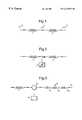
- FIG. 1is a schematic diagram illustrating pulse transmission through a previously proposed optical waveguide in series with a dispersion compensating fibre element for use in explaining the invention
- FIG. 2shows pumping of a dispersion compensating fibre element to enable Raman amplification which may optionally be used in a first embodiment
- FIG. 3shows this first embodiment without the pumped option shown in FIG. 2, but with a dispersion compensating fibre unit equipped with multiple distributed reflection elements.
- a silica optical fibre waveguide 1typically exhibits dispersion which distorts transmitted signals having substantial bandwidth.
- One previously proposed solution which is rather inadequateis to operate at 1.311 m or at whatever wavelength around which dispersion is a minimum.
- minimum power lossoccurs at very different wavelengths from minimum dispersion.
- a length of dispersion compensating fibre 2is required in series with fibre 1 .
- an input pulse of waveform 3may be broadened to waveform 4 by the transmission fibre 1 , and then the distortion is compensated by the correct length of dispersion compensating fibre 2 to recover the original pulse width and shape, as indicated by the approximately square pulse 3 i resembling substantially the original waveform 3 .
- FIG. 2shows this option in which waveguide 1 is compensated for dispersion by the use of dispersion compensating fibre 5 . Because the dispersion compensating fibre 5 is lossy, it is pumped by means of a diode laser 6 at a power just enough to cause stimulated Raman gain at a downshifted frequency.
- a conventional dispersion compensating fibree.g. of highly doped germania silica
- Such Raman amplifiersmay be pumped at shorter wavelengths by arranging for intermediate Raman orders to oscillate in a resonator defined by the amplifier A.
- a second embodimentuses pairs of Bragg gratings in the side of the dispersion compensating fibre, each pair defining a respective cavity along the dispersion compensating fibre, such as to cause oscillations selectively at the respective other orders, and thereby to transfer a substantial amount of the power, at one or more of the unwanted orders, from the pump signal to the desired order to give amplification to the signal.
- a diode-pumped Nd:YAG lasertransmits 1319 nm wavelength pumping power to a dispersion compensating fibre such as that schematically shown at 5 in FIG. 2 .
- the required signal amplificationis to be at 1.55 ⁇ m (i.e. 1550 nm), at which wavelength a standard dispersion compensating fibre is highly dispersive, then certain unwanted orders at 1380 nm and 1460 nm are generated by oscillations and are unrelated to the incident 1.5511 m signal.
- spaced grating pairsnot shown
- oscillatory cavitiesare set up which transfer the energy at these unwanted wavelengths to energy at a wanted wavelength.
- This optionthus comprises a dispersion compensating fibre including oscillatory cavities defined by reflective gratings at unrequired oscillatory wavelengths unrelated to a required signal wavelength of operation, wherein all these wavelengths, required and unrequired, are or tend to be Raman signals generated by pumping the dispersion compensating fibre, e.g. by means of a standard diode pumped Nd:YAG laser, and the required signal is responsive also to an incident signal and is amplified enough to compensate for losses in the Ddispersion compensating fibre and in line 1 .
- the wanted signalcan be recovered from downstream of the reflective grating pair or pairs (not shown).
- FIG. 3An embodiment of the invention is described with reference to FIG. 3, in which the wanted amplified signal is derived by reflection from an optical grating.
- the dispersion compensating fibre 8is caused to reflect the wanted signal from optical transmission line 1 to a circulator or other directional coupler 9 and thence to a detector or utilisation circuit 10 ; unwanted signals may be transmitted through a through-path 11 of the dispersion compensating fibre 8 in FIG. 3 . Alternatively all signals may be reflected at 11 .
- Amplification to compensate for losses if desiredmay be arranged as in FIG. 2 by pumping and by selected Raman molecular transitions.
- a problem with dispersion compensating fibreis that of selecting the appropriate length, desirably for economy's sake from a given length, whereby to introduce the appropriate amount of compensation for the dispersion caused by perhaps 50 kM or some unknown length of transmission waveguide 1 .
- One prior proposed way of selecting dispersion compensating fibre lengthsis by cutting off sections, which tends to be inconvenient and which for WDM systems results in a compromise in throughput. Accordingly by this embodiment of FIG.
- reflection pointsare created at one or more of the positions G 1 , G 2 , G 3 by means of Bragg gratings of appropriate element spacing which determine reflection wavelength or frequency, and of appropriate grating length which determines bandwidth of wavelength energy reflected, If G 1 is operative, the incident signals at this frequency will be selectively reflected at this frequency, and will traverse the first section, shown leftward of dispersion compensating fibre 8 , twice, introducing dispersion corresponding to this double length, then leftwards to circulator 9 and branched to utilisation circuit 10 .
- different reflecting gratings G 2 or G 3are used at appropriate positions or appropriate grating element spacings respectively, either of these wavelengths being transmitted past grating G 1 with negligible reflection. If grating G1 is likely not to be required, it can be erased in non-destructive manner by heating or irradiation by UV. New radiation gratings G can be added, e.g. they can be spliced in place as required. The position of a grating G determines the dispersion, and the spacing between grating elements in a grating G determines the wavelength selected by reflection.
- Raman amplification by pumping the dispersion compensating fibre materialwill usually be required, as described for FIG. 2, but occasionally may be deemed unnecessary if the dispersion compensating fibre 8 or optical waveguide line 1 does not introduce excessive power losses.
- Variations of the arrangement of FIG. 3may be used in further embodiments to separate energy at different wavelength in wavelength division multiplexers (WDM).
- WDMwavelength division multiplexers
- the two or more gratings Gwill be located by splicing in place or otherwise, at appropriate distances down the dispersion compensating fibre 8 , to give the requisite equalisation for energy at each of the different wavelengths.
- a further reflecting grating(not shown) can be located downstream of the other components of grating element spacing selected to reflect energy at the pump frequency. The reflected energy will reinforce the incident pump energy to result in a higher overall gain.
- Another alternative pumping schemeis to locate a pump source at both ends of the dispersion compensating fibre 5 of FIG. 2, when Raman amplification is employed, thus again increasing gain when required.
Landscapes
- Physics & Mathematics (AREA)
- Chemical & Material Sciences (AREA)
- Dispersion Chemistry (AREA)
- General Physics & Mathematics (AREA)
- Optics & Photonics (AREA)
- Electromagnetism (AREA)
- Engineering & Computer Science (AREA)
- Computer Networks & Wireless Communication (AREA)
- Signal Processing (AREA)
- Optical Communication System (AREA)
- Lasers (AREA)
- Optical Modulation, Optical Deflection, Nonlinear Optics, Optical Demodulation, Optical Logic Elements (AREA)
Abstract
Description
Claims (6)
Applications Claiming Priority (3)
| Application Number | Priority Date | Filing Date | Title |
|---|---|---|---|
| GB9614244 | 1996-07-06 | ||
| GB9614244AGB2315177A (en) | 1996-07-06 | 1996-07-06 | Dispersion compensating waveguide for optical transmission systems |
| PCT/GB1997/001783WO1998001781A1 (en) | 1996-07-06 | 1997-07-03 | Dispersion compensating waveguide for optical transmission systems |
Publications (1)
| Publication Number | Publication Date |
|---|---|
| US6215929B1true US6215929B1 (en) | 2001-04-10 |
Family
ID=10796492
Family Applications (1)
| Application Number | Title | Priority Date | Filing Date |
|---|---|---|---|
| US09/214,448Expired - LifetimeUS6215929B1 (en) | 1996-07-06 | 1997-07-03 | Dispersion compensating waveguide for optical transmission systems |
Country Status (6)
| Country | Link |
|---|---|
| US (1) | US6215929B1 (en) |
| EP (1) | EP1010026B1 (en) |
| CA (1) | CA2259546A1 (en) |
| DE (1) | DE69710930T2 (en) |
| GB (1) | GB2315177A (en) |
| WO (1) | WO1998001781A1 (en) |
Cited By (6)
| Publication number | Priority date | Publication date | Assignee | Title |
|---|---|---|---|---|
| US20020118934A1 (en)* | 2001-02-23 | 2002-08-29 | Yochay Danziger | Method and system for dispersion management with Raman amplification |
| US6526208B1 (en)* | 2000-11-27 | 2003-02-25 | Nortel Networks Limited | Dispersion managed fiber optic cable and system |
| US20040052452A1 (en)* | 2002-09-13 | 2004-03-18 | Honeywell International, Inc. | Wavelength division multiplexing coupler with loss element |
| US20040105685A1 (en)* | 1997-07-31 | 2004-06-03 | Btg International Limited | Optical fibre communication system |
| US7352970B2 (en) | 1995-11-27 | 2008-04-01 | Btg International Limited | Dispersion management system for soliton optical transmission system |
| US20100079853A1 (en)* | 2008-05-01 | 2010-04-01 | Rakich Peter T | Optimized cascaded raman fiber-based laser source for high efficiency mid-infrared spectral generation |
Families Citing this family (4)
| Publication number | Priority date | Publication date | Assignee | Title |
|---|---|---|---|---|
| US5812712A (en)* | 1997-02-26 | 1998-09-22 | E-Tek Dynamics, Inc. | Fiber bragg grating-circulator systems having reduced ASE |
| US6295396B1 (en)* | 1999-06-04 | 2001-09-25 | Qtera Corporation | Method and apparatus for higher-order chromatic dispersion compensation |
| GB2368479A (en)* | 2000-10-24 | 2002-05-01 | Marconi Comm Ltd | Dispersion compensator |
| GB0108084D0 (en)* | 2001-03-30 | 2001-05-23 | Marconi Comm Ltd | Method and apparatus for providing dispersion in dispersion compensation modules |
Citations (8)
| Publication number | Priority date | Publication date | Assignee | Title |
|---|---|---|---|---|
| EP0485100A2 (en) | 1990-11-09 | 1992-05-13 | Nortel Networks Corporation | Optical amplifiers |
| EP0559356A1 (en) | 1992-03-04 | 1993-09-08 | Nortel Networks Corporation | Optical repeaters |
| US5404413A (en) | 1993-12-14 | 1995-04-04 | At&T Corp. | Optical circulator for dispersion compensation |
| US5410624A (en) | 1993-09-01 | 1995-04-25 | Northern Telecom Limited | Filter for a wavelength division multiplex system |
| EP0732819A2 (en) | 1995-03-15 | 1996-09-18 | Sumitomo Electric Industries, Ltd. | Chromatic dispersion compensator and chromatic dispersion compensating optical communication system |
| US5574810A (en)* | 1994-06-01 | 1996-11-12 | Northern Telecom Limited | Incubated Bragg gratings in waveguides |
| US5608562A (en)* | 1994-05-25 | 1997-03-04 | Lucent Technologies Inc. | Optical communications system with adjustable dispersion compensation |
| US6072811A (en)* | 1998-02-11 | 2000-06-06 | Imra America | Integrated passively modelocked fiber lasers and method for constructing the same |
Family Cites Families (4)
| Publication number | Priority date | Publication date | Assignee | Title |
|---|---|---|---|---|
| GB2161612B (en)* | 1984-07-11 | 1988-02-03 | Stc Plc | Optical fibre transmission systems |
| US5093876A (en)* | 1990-07-27 | 1992-03-03 | At&T Bell Laboratories | WDM systems incorporating adiabatic reflection filters |
| US5210807A (en)* | 1992-06-29 | 1993-05-11 | The United States Of America As Represented By The Secretary Of The Navy | Variable wide band fiber optic delay line |
| DE4332841A1 (en)* | 1993-09-27 | 1995-03-30 | Siemens Ag | Arrangement for delaying an optical signal |
- 1996
- 1996-07-06GBGB9614244Apatent/GB2315177A/ennot_activeWithdrawn
- 1997
- 1997-07-03USUS09/214,448patent/US6215929B1/ennot_activeExpired - Lifetime
- 1997-07-03CACA002259546Apatent/CA2259546A1/ennot_activeAbandoned
- 1997-07-03EPEP97929419Apatent/EP1010026B1/ennot_activeExpired - Lifetime
- 1997-07-03WOPCT/GB1997/001783patent/WO1998001781A1/enactiveIP Right Grant
- 1997-07-03DEDE69710930Tpatent/DE69710930T2/ennot_activeExpired - Fee Related
Patent Citations (9)
| Publication number | Priority date | Publication date | Assignee | Title |
|---|---|---|---|---|
| EP0485100A2 (en) | 1990-11-09 | 1992-05-13 | Nortel Networks Corporation | Optical amplifiers |
| EP0559356A1 (en) | 1992-03-04 | 1993-09-08 | Nortel Networks Corporation | Optical repeaters |
| US5410624A (en) | 1993-09-01 | 1995-04-25 | Northern Telecom Limited | Filter for a wavelength division multiplex system |
| US5404413A (en) | 1993-12-14 | 1995-04-04 | At&T Corp. | Optical circulator for dispersion compensation |
| US5608562A (en)* | 1994-05-25 | 1997-03-04 | Lucent Technologies Inc. | Optical communications system with adjustable dispersion compensation |
| US5574810A (en)* | 1994-06-01 | 1996-11-12 | Northern Telecom Limited | Incubated Bragg gratings in waveguides |
| EP0732819A2 (en) | 1995-03-15 | 1996-09-18 | Sumitomo Electric Industries, Ltd. | Chromatic dispersion compensator and chromatic dispersion compensating optical communication system |
| US5701188A (en)* | 1995-03-15 | 1997-12-23 | Sumitomo Electric Industries, Ltd. | Chromatic dispersion compensator and chromatic dispersion compensating optical communication system |
| US6072811A (en)* | 1998-02-11 | 2000-06-06 | Imra America | Integrated passively modelocked fiber lasers and method for constructing the same |
Cited By (9)
| Publication number | Priority date | Publication date | Assignee | Title |
|---|---|---|---|---|
| US7352970B2 (en) | 1995-11-27 | 2008-04-01 | Btg International Limited | Dispersion management system for soliton optical transmission system |
| US20090087190A1 (en)* | 1995-11-27 | 2009-04-02 | Nicholas John Doran | Optical communications |
| US20040105685A1 (en)* | 1997-07-31 | 2004-06-03 | Btg International Limited | Optical fibre communication system |
| US6526208B1 (en)* | 2000-11-27 | 2003-02-25 | Nortel Networks Limited | Dispersion managed fiber optic cable and system |
| US20020118934A1 (en)* | 2001-02-23 | 2002-08-29 | Yochay Danziger | Method and system for dispersion management with Raman amplification |
| US20040052452A1 (en)* | 2002-09-13 | 2004-03-18 | Honeywell International, Inc. | Wavelength division multiplexing coupler with loss element |
| US6888981B2 (en) | 2002-09-13 | 2005-05-03 | Honeywell International Inc. | Wavelength division multiplexing coupler with loss element |
| US20100079853A1 (en)* | 2008-05-01 | 2010-04-01 | Rakich Peter T | Optimized cascaded raman fiber-based laser source for high efficiency mid-infrared spectral generation |
| US8189257B2 (en)* | 2008-05-01 | 2012-05-29 | Massachusetts Institute Of Technology | Optimized cascaded raman fiber-based laser source for high efficiency mid-infrared spectral generation |
Also Published As
| Publication number | Publication date |
|---|---|
| WO1998001781A1 (en) | 1998-01-15 |
| GB2315177A (en) | 1998-01-21 |
| DE69710930T2 (en) | 2002-11-28 |
| GB9614244D0 (en) | 1996-09-04 |
| DE69710930D1 (en) | 2002-04-11 |
| CA2259546A1 (en) | 1998-01-15 |
| EP1010026B1 (en) | 2002-03-06 |
| EP1010026A1 (en) | 2000-06-21 |
| GB2315177A8 (en) | 1998-02-05 |
Similar Documents
| Publication | Publication Date | Title |
|---|---|---|
| EP0938172B1 (en) | Apparatus comprising an improved cascaded optical fiber raman device | |
| EP0559356B1 (en) | Optical repeaters | |
| JP3476956B2 (en) | Optical systems and devices using long-period spectral shaping devices | |
| JP4425740B2 (en) | Optical amplifier | |
| KR100686417B1 (en) | Fiber optic amplifier with gain flattening filter | |
| US5978131A (en) | In-fiber two-stage amplifier providing WDM signal conditioning | |
| US6317239B1 (en) | Optical repeaters for single- and multi-wavelength operation with dispersion equalization | |
| JP3969807B2 (en) | Dispersion compensation device | |
| US6215929B1 (en) | Dispersion compensating waveguide for optical transmission systems | |
| US6204958B1 (en) | Optical amplifier having a substantially flat gain spectrum | |
| US6337939B1 (en) | Optical amplifier monitor using a blazed grating | |
| CA2248477C (en) | Optical dispersion compensation | |
| EP0779689B1 (en) | Gain clamped optical amplifier | |
| US6721088B2 (en) | Single-source multiple-order raman amplifier for optical transmission systems | |
| JP2002506281A (en) | Ultra-wideband low noise gain flattened rare earth doped fiber amplifier | |
| US6438287B1 (en) | Dispersion compensation | |
| EP0964486B1 (en) | Optical fiber amplifier | |
| JP2002094152A (en) | Optical amplification | |
| JP2006064852A (en) | Dispersion compensator | |
| KR100396266B1 (en) | Gain flattening device of a fiber amplifier | |
| JP2009065180A (en) | Optical monitor circuit | |
| JP2834528B2 (en) | Optical fiber amplifier parts | |
| JP2749643B2 (en) | Light coupler | |
| JP2002204206A (en) | Polarization-maintaining gain equalizer |
Legal Events
| Date | Code | Title | Description |
|---|---|---|---|
| AS | Assignment | Owner name:NORTHERN TELECOM LIMITED, CANADA Free format text:ASSIGNMENT OF ASSIGNORS INTEREST;ASSIGNOR:BYRON, KEVIN CHRISTOPHER;REEL/FRAME:009885/0243 Effective date:19981214 | |
| AS | Assignment | Owner name:NORTEL NETWORKS CORPORATION, CANADA Free format text:CHANGE OF NAME;ASSIGNOR:NORTHERN TELECOM LIMITED;REEL/FRAME:010567/0001 Effective date:19990429 | |
| AS | Assignment | Owner name:NORTEL NETWORKS LIMITED, CANADA Free format text:CHANGE OF NAME;ASSIGNOR:NORTEL NETWORKS CORPORATION;REEL/FRAME:011195/0706 Effective date:20000830 Owner name:NORTEL NETWORKS LIMITED,CANADA Free format text:CHANGE OF NAME;ASSIGNOR:NORTEL NETWORKS CORPORATION;REEL/FRAME:011195/0706 Effective date:20000830 | |
| AS | Assignment | Owner name:NORTEL NETWORKS CORPORATION, CANADA Free format text:CHANGE OF NAME;ASSIGNOR:NORTHERN TELECOM LIMITED;REEL/FRAME:011540/0325 Effective date:19990427 | |
| AS | Assignment | Owner name:NORTEL NETWORKS LIMITED, CANADA Free format text:CHANGE OF NAME;ASSIGNOR:NORTEL NETWORKS CORPORATION;REEL/FRAME:011583/0468 Effective date:20000501 | |
| STCF | Information on status: patent grant | Free format text:PATENTED CASE | |
| FPAY | Fee payment | Year of fee payment:4 | |
| FPAY | Fee payment | Year of fee payment:8 | |
| AS | Assignment | Owner name:ROCKSTAR BIDCO, LP, NEW YORK Free format text:ASSIGNMENT OF ASSIGNORS INTEREST;ASSIGNOR:NORTEL NETWORKS LIMITED;REEL/FRAME:027164/0356 Effective date:20110729 | |
| FPAY | Fee payment | Year of fee payment:12 | |
| AS | Assignment | Owner name:ROCKSTAR CONSORTIUM US LP, TEXAS Free format text:ASSIGNMENT OF ASSIGNORS INTEREST;ASSIGNOR:ROCKSTAR BIDCO, LP;REEL/FRAME:032389/0800 Effective date:20120509 | |
| AS | Assignment | Owner name:RPX CLEARINGHOUSE LLC, CALIFORNIA Free format text:ASSIGNMENT OF ASSIGNORS INTEREST;ASSIGNORS:ROCKSTAR CONSORTIUM US LP;ROCKSTAR CONSORTIUM LLC;BOCKSTAR TECHNOLOGIES LLC;AND OTHERS;REEL/FRAME:034924/0779 Effective date:20150128 | |
| AS | Assignment | Owner name:JPMORGAN CHASE BANK, N.A., AS COLLATERAL AGENT, IL Free format text:SECURITY AGREEMENT;ASSIGNORS:RPX CORPORATION;RPX CLEARINGHOUSE LLC;REEL/FRAME:038041/0001 Effective date:20160226 | |
| AS | Assignment | Owner name:RPX CLEARINGHOUSE LLC, CALIFORNIA Free format text:RELEASE (REEL 038041 / FRAME 0001);ASSIGNOR:JPMORGAN CHASE BANK, N.A.;REEL/FRAME:044970/0030 Effective date:20171222 Owner name:RPX CORPORATION, CALIFORNIA Free format text:RELEASE (REEL 038041 / FRAME 0001);ASSIGNOR:JPMORGAN CHASE BANK, N.A.;REEL/FRAME:044970/0030 Effective date:20171222 |