US6215827B1 - System and method for measuring channel quality information in a communication system - Google Patents
System and method for measuring channel quality information in a communication systemDownload PDFInfo
- Publication number
- US6215827B1 US6215827B1US09/044,636US4463698AUS6215827B1US 6215827 B1US6215827 B1US 6215827B1US 4463698 AUS4463698 AUS 4463698AUS 6215827 B1US6215827 B1US 6215827B1
- Authority
- US
- United States
- Prior art keywords
- metric
- signal
- plus noise
- interference plus
- value
- Prior art date
- Legal status (The legal status is an assumption and is not a legal conclusion. Google has not performed a legal analysis and makes no representation as to the accuracy of the status listed.)
- Expired - Lifetime
Links
Images


Classifications
- H—ELECTRICITY
- H04—ELECTRIC COMMUNICATION TECHNIQUE
- H04L—TRANSMISSION OF DIGITAL INFORMATION, e.g. TELEGRAPHIC COMMUNICATION
- H04L1/00—Arrangements for detecting or preventing errors in the information received
- H04L1/0001—Systems modifying transmission characteristics according to link quality, e.g. power backoff
- H04L1/0015—Systems modifying transmission characteristics according to link quality, e.g. power backoff characterised by the adaptation strategy
- H—ELECTRICITY
- H04—ELECTRIC COMMUNICATION TECHNIQUE
- H04L—TRANSMISSION OF DIGITAL INFORMATION, e.g. TELEGRAPHIC COMMUNICATION
- H04L1/00—Arrangements for detecting or preventing errors in the information received
- H04L1/0001—Systems modifying transmission characteristics according to link quality, e.g. power backoff
- H04L1/0002—Systems modifying transmission characteristics according to link quality, e.g. power backoff by adapting the transmission rate
- H04L1/0003—Systems modifying transmission characteristics according to link quality, e.g. power backoff by adapting the transmission rate by switching between different modulation schemes
- H—ELECTRICITY
- H04—ELECTRIC COMMUNICATION TECHNIQUE
- H04L—TRANSMISSION OF DIGITAL INFORMATION, e.g. TELEGRAPHIC COMMUNICATION
- H04L1/00—Arrangements for detecting or preventing errors in the information received
- H04L1/0001—Systems modifying transmission characteristics according to link quality, e.g. power backoff
- H04L1/0009—Systems modifying transmission characteristics according to link quality, e.g. power backoff by adapting the channel coding
- H—ELECTRICITY
- H04—ELECTRIC COMMUNICATION TECHNIQUE
- H04L—TRANSMISSION OF DIGITAL INFORMATION, e.g. TELEGRAPHIC COMMUNICATION
- H04L1/00—Arrangements for detecting or preventing errors in the information received
- H04L1/0001—Systems modifying transmission characteristics according to link quality, e.g. power backoff
- H04L1/0023—Systems modifying transmission characteristics according to link quality, e.g. power backoff characterised by the signalling
- H04L1/0026—Transmission of channel quality indication
- H—ELECTRICITY
- H04—ELECTRIC COMMUNICATION TECHNIQUE
- H04L—TRANSMISSION OF DIGITAL INFORMATION, e.g. TELEGRAPHIC COMMUNICATION
- H04L1/00—Arrangements for detecting or preventing errors in the information received
- H04L1/004—Arrangements for detecting or preventing errors in the information received by using forward error control
- H04L1/0045—Arrangements at the receiver end
- H04L1/0054—Maximum-likelihood or sequential decoding, e.g. Viterbi, Fano, ZJ algorithms
- H—ELECTRICITY
- H04—ELECTRIC COMMUNICATION TECHNIQUE
- H04L—TRANSMISSION OF DIGITAL INFORMATION, e.g. TELEGRAPHIC COMMUNICATION
- H04L1/00—Arrangements for detecting or preventing errors in the information received
- H04L1/004—Arrangements for detecting or preventing errors in the information received by using forward error control
- H04L1/0056—Systems characterized by the type of code used
- H04L1/0059—Convolutional codes
- H04L1/006—Trellis-coded modulation
- H—ELECTRICITY
- H04—ELECTRIC COMMUNICATION TECHNIQUE
- H04L—TRANSMISSION OF DIGITAL INFORMATION, e.g. TELEGRAPHIC COMMUNICATION
- H04L1/00—Arrangements for detecting or preventing errors in the information received
- H04L1/20—Arrangements for detecting or preventing errors in the information received using signal quality detector
- H—ELECTRICITY
- H04—ELECTRIC COMMUNICATION TECHNIQUE
- H04W—WIRELESS COMMUNICATION NETWORKS
- H04W36/00—Hand-off or reselection arrangements
- H04W36/24—Reselection being triggered by specific parameters
- H04W36/30—Reselection being triggered by specific parameters by measured or perceived connection quality data
- H04W36/302—Reselection being triggered by specific parameters by measured or perceived connection quality data due to low signal strength
- H—ELECTRICITY
- H04—ELECTRIC COMMUNICATION TECHNIQUE
- H04L—TRANSMISSION OF DIGITAL INFORMATION, e.g. TELEGRAPHIC COMMUNICATION
- H04L1/00—Arrangements for detecting or preventing errors in the information received
- H04L1/12—Arrangements for detecting or preventing errors in the information received by using return channel
- H—ELECTRICITY
- H04—ELECTRIC COMMUNICATION TECHNIQUE
- H04W—WIRELESS COMMUNICATION NETWORKS
- H04W72/00—Local resource management
- H04W72/50—Allocation or scheduling criteria for wireless resources
- H04W72/54—Allocation or scheduling criteria for wireless resources based on quality criteria
Definitions
- the present inventionrelates generally to digital communication systems and, more particularly, to communications systems which utilize digital transmission schemes.
- the difficulty in obtaining these metrics in communications systems such as cellular systemsis based on the time varying signal strength levels found on the cellular channel. These time varying effects, referred to as fading and distance dependent loss, are the result of the movement of the mobile station (cellular phone) relative to the base station (also known as a cell site).
- Some recent schemespropose a short-term prediction of the FER, but not the SIR, using the metric for the second best path in a Viterbi decoder. This metric is computationally very intensive and reacts to short term variations in fading conditions. Therefore, there is a need, for an efficient and accurate method for measuring the channel quality in terms of the SIR in a communication system.
- FERmobile assisted handoff
- MAHOmobile assisted handoff
- FER measurementsare usually very slow for the purpose of rate adaptation, power control and handoff.
- FER as a channel quality metricis slow because it can take a very long time for the mobile to count a sufficient number of frame errors. Therefore, there is a need for a robust short-term channel quality indicator that can be related to the FER.
- channel quality metricssuch as symbol error rate, average bit error rate and received signal strength measurements have been proposed as alternatives.
- the IS-136 standardalready specifies measurement procedures for both bit error rate and received signal strength.
- these measuresdo not correlate well with the FER, or the SIR, which is widely accepted as the meaningful performance measure in wireless systems.
- received signal strength measurementsare often inaccurate and unreliable.
- the SIRis a more appropriate as a handoff metric near the cell boundary where signal quality is rapidly changing.
- the present inventionis directed to overcoming, or at least reducing the effects of one or more of the problems set forth above.
- This invention and methodsare directed to determining the SIR for a digital communication system with a fading channel. While the following examples are directed to wireless communications such as cellular telephones the invention and methods descried apply equally well to non-wireless communications.
- a system and methodfor determining the path metrics of the communication system corresponding to a set of predetermined SIR values.
- a digital signalis received and a path metric determined for the digital signal. Mapping of the path metric is provided to a corresponding SIR in the set of predetermined SIR values.
- FIG. 1is a graphical representation of three cell sites within a cluster
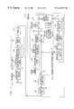
- FIG. 2is a block diagram of both the base station and the mobile station transmitters and receivers for the present invention
- FIG. 3is a block diagram of a coherent decoder system for present invention
- FIG. 4is a block diagram of a non-coherent decoder system for present invention.
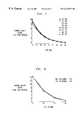
- FIG. 5is a graph having a curve, with the vertical scale representing the average Viterbi decoder metric and the horizontal scale representing the time slot number;
- FIG. 6is a graph having a curve, with the vertical scale representing the average Viterbi decoder metric and the horizontal scale representing the SIR;
- FIG. 7is a graph having a curve, with the vertical scale representing the long term average of the channel quality metric and the horizontal scale representing the SIR for the voice limited case, with no fading interference;
- FIG. 8is a graph having a curve, with the vertical scale representing the long term average of the channel quality metric and the horizontal scale representing the SIR for the interference limited case, with a single dominant interferer at 20 dB above the background noise level;
- FIG. 9is a graph having a curve, with the vertical scale representing the SIR average error in dB and the horizontal scale representing the averaging duration for different Doppler frequencies and 0 dB of interference;
- FIG. 10is a graph having a curve, with the vertical scale representing the SIR average error in dB and the horizontal scale representing the averaging duration for different Doppler frequencies and for the interference limited case, with a single dominant interferer at20 dB above the background noise level;
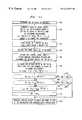
- FIG. 11is a flow diagram illustrating the steps performed during the process of determining the SIR using the lookup table and adjusting the coded modulation scheme used by the system;
- FIG. 12is a flow diagram illustrating the steps performed during the process of determining the SIR using the linear prediction and adjusting the coded modulation scheme used by the system;
- FIG. 13is a graph having three curves, with the vertical scale representing the ⁇ overscore (FER) ⁇ and the horizontal scale representing the SIR;
- FIG. 14is a table of values for a conservative mode adaptation strategy based on a Viterbi algorithm metric average
- FIG. 15is a table of values for an aggressive mode adaptation strategy based on a Viterbi algorithm metric average
- FIG. 16is a block diagram of both the base station and the mobile station transmitters and receivers for the implementation of an adaptive coding scheme
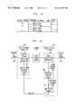
- FIG. 17is a block diagram of both the base station and the mobile station transmitters and receivers for the implementation of a mobile handoff scheme and a power control scheme.
- each cell 2 , 4 , and 6is shown having a hexagonal cell boundary.
- base stations 8 , 10 , and 12that are located near the center of the corresponding cell 2 , 4 , and 6 .
- the base station 8is located within cell 2
- base station 10is located within cell 4
- base station 12is located within cell 6 .
- the boundaries 14 , 16 and 18 separating the cells 2 , 4 , and 6generally represent the points where mobile assisted handoff occurs.
- the SIR from the base station 8will drop below a certain threshold level past the boundary 14 while, at the same time, the SIR from the second base station 10 increases above this threshold as the mobile station 20 crosses the boundary 14 into cell 4 .
- Cellular systemsare engineered to provide coverage from each base station up until the cell boundary.
- the SIR over a large portion of a cell 2is sufficient to support higher data rates because the SIR from the base station 8 is greater than the minimum SIR needed to support the data transfer at the boundary 14 .
- FIG. 2is an example implementation of an adaptive rate system that takes advantage of this support for higher data rates.
- FIG. 2is a block diagram for the schematic of the base station 8 and the mobile station 20 for the invention.
- the base station 8consists of both an adaptive rate base station transmitter 22 and an adaptive rate base station receiver 24 .
- the mobile station 20also consists of both an adaptive rate mobile station receiver 26 and an adaptive rate mobile transmitter 28 .
- Each pair of the transmitter and the receiver, corresponding to either the base station 8 or mobile station 20are in radio connection via a corresponding channel.
- the adaptive rate base station transmitter 22is connected through a dowry radio channel 30 to the adaptive rate mobile receiver 26 and the adaptive rate mobile station transmitter 28 is connected through an uplink radio channel 32 to the adaptive rate base station receiver 24 .
- This implementationallows for increased throughput between the base station 8 and the mobile station 20 over both the downlink channel 30 and the uplink channel 32 because of the use of adaptive bandwidth efficient coded modulation schemes.
- the information ratemay be varied by transmitting at a fixed symbol rate (as in IS-130/IS-136), and changing the bandwidth efficiency (number of information bits per symbol) using a choice of coded modulation schemes.
- coded modulation schemes with different bandwidth efficiencieshave different error rate performance for the same SIR per symbol.
- the coded modulation schemeis chosen which results in the highest throughput with acceptable FER and retransmission delay. Therefore, detection of channel quality in terms of SIR or achievable FER is very important for this invention.
- Both the SIR and FER as channel quality metricscan be derived from the appropriately weighted cumulative Euclidean distance metric corresponding to a decoded received sequence.
- FIG. 3A block diagram of a encoder and decoder for use with a coherently modulated system in accordance with the invention is shown in FIG. 3.
- a transmitter 34receives an information sequence ⁇ a k ⁇ 36 which is encoded using a convolutional encoder 38 to provide a coded sequence ⁇ b k ⁇ 40 .
- the coded sequence ⁇ b k ⁇ 40is then mapped through a symbol mapper 42 to a symbol ⁇ s k ⁇ 44 from either an M-ary constellation such as M-ary phase shift keying (M-PSK) or a M-ary quadrature amplitude modulation (M-QAM) scheme using either a straightforward Gray mapping or a set partitioning technique.
- M-PSKM-ary phase shift keying
- M-QAMM-ary quadrature amplitude modulation
- Pulseshapingis then carried out using transmit filters 46 that satisfy the Gibby Smith constraints (i.e. necessary and sufficient conditions for zero intersymbol interference).
- the symbol ⁇ s k ⁇ 44is then transmitted through the channel 48 to a receiver 50 .
- the front end analog receive filters 52are assumed to be matched to the transmit filters 46 and an output ⁇ r k ⁇ 54 is sampled at the optimum sampling instants.
- s kdenotes the complex transmitted symbol ⁇ s k ⁇ 44
- a krepresents the complex fading channel 64 coefficient
- n kdenotes the complex additive white Gaussian noise (AWGN) with variance N o .
- the fading channel 64is assumed to be correlated, and may be represented by a number of models. In this example the Jakes' model for Rayleigh fading is used.
- the convolutional encoder 38is chosen to optimize the needs of the system.
- a trellis codewas chosen, however, many other codes could also be used by this invention without modifying the essence of the invention.
- Maximum likelihood decoding at the receiver 50may be carried out using a Viterbi algorithm circuit, also known as a maximum likelihood decoder (MLD) 56 to search for the best path through a trellis.
- MLDmaximum likelihood decoder
- An estimate of the complex fading channel 64 coefficientsis assumed available to the decoder (i.e. the convolutional encoder 58 ) of the receiver 50 .
- the Viterbi algorithm circuit of the MLD 56associates an incremental Euclidean distance metric with each trellis branch transition and tries to find the transmitted sequence ⁇ s k ⁇ 44 that is closest in Euclidean distance to the received sequence ⁇ r k ⁇ 54 .
- the Viterbi algorithm circuit of the MLD 56processes each possible data sequence ⁇ k ⁇ 65 through both a convolutional encoder 58 and symbol mapper 60 to produce a possible decoded sequence ⁇ tilde over (s) ⁇ k ⁇ 62 .
- the Viterbi algorithm circuit of the MLD 56uses the received sequence ⁇ r k ⁇ 54 and the estimated channel coefficient ⁇ a k ⁇ 64 in an incremental Euclidean distance metric computation circuit 66 which computes the incremental Euclidean distance.
- the incremental Euclidean distance metricis then processed through a cumulative feedback loop 68 that produces the cumulative path metric 72 .
- the cumulative path metric 72 and the cumulative metrics corresponding to all other possible transmitted sequences ⁇ k ⁇ 70are inputted into a minimum metric processor circuit 74 which outputs both the decoded data sequence ⁇ â ; k ⁇ 76 and the minimum metric m i for the i th block.
- a k 64is the estimated fading channel coefficient at the k th instant, and the trellis is assumed to terminate at a known state after every N symbols.
- FIG. 3describes the invention using a coherent modulation system such as M-PSK or M-QAM
- the inventionalso applies a similar metric computational method to a non-coherent modulation system.
- the computation of the Euclidean distance metricassumes that the signals are coherently demodulated, and that an estimate of the channel coefficients is available to the receiver.
- M-DPSKM-ary differential phase shift keying
- M-DPSK systemssuch as in the IS-136 standard allow a much simpler receiver structure compared to a coherent system of FIG. 3 because M-DPSK signals are often differentially demodulated prior to decoding.
- M-DPSK signalsare often differentially demodulated prior to decoding.
- the determination of the Euclidean distance metric for M-DPSK signalsis not directly an accurate measure of the SIR.
- FIG. 4describes an alternative example that uses an appropriately weighted or scaled Euclidean distance metric for M-DPSK signals which obtains a quick and reliable indicator of SIR in noise limited, interference limited and delay spread environments.
- FIG. 4shows a block diagram of an encoder and decoder for a M-DPSK system.
- the information sequence ⁇ a k ⁇ 82is encoded using a convolutional encoder 84 to provide a coded sequence ⁇ b k ⁇ 86 .
- the coded sequence ⁇ b k ⁇ 86is then mapped through a M-DPSK symbol mapper 88 to a M-DPSK symbol ⁇ s k ⁇ 96 .
- the M-DPSK mappingis carried out in two steps. First, coded sequence ⁇ b k ⁇ 86 is mapped to M-ary symbols, ⁇ d k ⁇ 92 , chosen from an M-ary constellation using either a mapping or partitioning circuit 90 .
- This mapping or partitioning circuit 90incorporates either a straightforward Gray mapping or a set partitioning technique. Then the M-ary symbols ⁇ d k ⁇ 92 are differentially modulated in a differential modulator 94 to obtain M-DPSK symbols ⁇ s k ⁇ 96 . Pulse shaping is then carried out using transmit filters 98 that satisfy the Gibby Smith constraints (i.e. necessary and sufficient conditions for zero intersymbol interference). The M-DPSK symbol ⁇ s k ⁇ 96 is then transmitted through the channel 100 to the receiver 102 . At the receiver 102 , the front-end analog receive filters 104 are assumed to be matched to the transmit filters 98 and the output ⁇ r k ⁇ 106 is sampled at the optimum sampling instants.
- r ka k s k + ⁇ k i k +n k ,
- s kd k d k-1 denotes the complex transmitted symbol ⁇ s k ⁇ 96
- a krepresents the complex fading channel coefficient for the desired signal
- ⁇ kdenotes the complex fading channel coefficient for an interfering signal
- n kdenotes the complex additive white Gaussian noise (AWGN) with variance N o .
- AWGNadditive white Gaussian noise
- a channel 100is assumed to be a fading correlated mobile radio channel, and may be represented by a number of models. In this example the Jakes' model for Rayleigh fading is used.
- the received symbol sequence ⁇ r k ⁇ 106is then differentially demodulated through a differential demodulator 108 that produces a demodulated sequence ⁇ y k ⁇ 110 given by
- a Maximum Likelihood Decoder (MLD) 112maps the demodulated sequence y k 110 to â ; k 132 . â ; k 132 is the decoded replica of the transmitted data sequence a k 82 .
- MLD 112One realization of the MLD 112 is the well-known Viterbi decoder.
- the set of transmitted M-ary sequencescan be mapped on to a trellis state transition diagram.
- the Viterbi algorithmis used to do a sequential search for the maximum likelihood path through the trellis.
- other realizations, other than the Viterbi decoderare possible for the MLD 112 and are known to those skilled in the art.
- the MLDassociates an incremental Euclidean distance metric with each trellis branch transition and tries to find the transmitted M-ary sequence ⁇ circumflex over (d) ⁇ k ⁇ that is closest in Euclidean distance to the demodulated sequence ⁇ y k ⁇ 110 .
- the MLD 112processes each possible data sequence ⁇ k ⁇ 114 through a convolutional encoder 116 and M-ary partitioning or mapping circuit 118 producing a possible M-ary sequence ⁇ tilde over (d) ⁇ k ⁇ 120 .
- the Viterbi algorithm circuit 112uses the demodulated sequence ⁇ y k ⁇ 110 and the M-ary sequence ⁇ tilde over (d) ⁇ k ⁇ 120 in an incremental Euclidean distance metric computation circuit 122 which computes the incremental Euclidean distance.
- the incremental Euclidean distance metricis then processed through a cumulative feedback loop 124 that produces the cumulative path metric 126 .
- the cumulative path metric 126 and the cumulative metrics 128 corresponding to all possible M-ary sequence ⁇ tilde over (d) ⁇ k ⁇ 120are input into a minimum metric processor circuit 130 which outputs the decoded data sequence ⁇ â ; k ⁇ 132 .
- the path that gives the minimum cumulative Euclidean distance metricis chosen and the corresponding data sequence ⁇ â ; k ⁇ 132 is the decoded output.
- the sequence ⁇ â ; k ⁇ 132is declared the received data sequence.
- the decoded data sequence ⁇ â ; k ⁇ 132is encoded using a convolutional encoder 134 and mapped to M-ary sequence ⁇ circumflex over (d) ⁇ k ⁇ 138 by the M-ary Partitioner or mapping circuit 136 .
- the convolutional encoder 134 and M-ary Partitioner or mapping circuit 136are at the receiver 102 but are identical to the transmitter 80 convolutional encoder 84 and M-ary Partitioner or mapping circuit 90 .
- the Viterbi decoderis used to derive the channel quality information from the cumulative Euclidean distance metric, for both the coherent and non-coherent systems, corresponding to the decoded trellis path for each block.
- the Euclidean distance metrichas large variations from one block to another in the presence of a fading channel. Thus smoothing, such as averaging, of these variation is required to obtain a good estimate of the metric.
- a small cumulative Euclidean distance metricwould indicate that the received sequence is very close to the decoded sequence. For well-designed trellis codes, this situation would only occur under good channel conditions with high SIR. Under poor channel conditions, the metric is much higher.
- a good estimate of the metriccan be obtained at the i th block of N symbols by using the following relationship:
- M ia M i-1 +(1 ⁇ a ) m i ,
- m irepresents the decoded trellis path metric and a represents the filter coefficient which determines the variance of the estimate.
- FIG. 5illustrates a graph having a four curves, with the vertical scale representing the average Viterbi decoder metric M i and the horizontal scale representing the block number.
- the solid line curves 144 - 150represent the time evolution of the filtered Viterbi decoder metric for a trellis coded 8 PSK scheme and a filter coefficient ⁇ equal to 0.9.
- the SNRranges from 30 dB to 16 dB and is decremented in steps of 2 dB after every 600 time slot pairs.
- FIG. 6shows a graph having four curves, with the vertical scale representing the long term average Viterbi decoder metric ⁇ (the expected value of M i ) and the horizontal scale representing the SIR.
- the four curves 152 - 158represent different doppler frequencies. From FIG. 6, it is clear that the average metric ⁇ does not depend on the mobile speed. As a result, the long term cumulative metric average, ⁇ , is the target metric for the present invention.
- the Euclidean metrichas been obtained it can be either mapped to the corresponding SIR in a lookup table or through a linear prediction approach.
- the average Viterbi decoder metricprovides a very good indication of the SIR.
- FIG. 5shows that the short term average satisfies ⁇ low ⁇ M i ⁇ ⁇ ⁇ high
- the thresholds, ⁇ low and ⁇ highdepend on the standard deviation of M i which, in turn, is a function of the filter parameter, a.
- the present inventionincorporates two possible ways to determine the SIR from the average metric M i .
- An IS-130/IS-136 time slot structureis assumed, and the trellis is terminated at the end of each time slot pair.
- the vertical axisrepresents the values of the long term average of the channel quality metric and the horizontal axis represents the SIR values in a noise limited environment C/N.
- the C/Nranges from 14 dB to 30 dB in steps of 2 dB.
- Each curverepresents a different combination of the coding scheme and ⁇ d , the doppler frequency, multiplied by T, the symbol duration.
- the average metricdoes not depend on the mobile speed or the choice of coding and modulation.
- FIG. 8shows that the long term average channel quality metric is consistent across Doppler frequencies even with fading interferers.
- FIG. 9shows the average error of the non-coherent metric.
- FIG. 9shows the average error E
- FIG. 9shows that at both low and high Doppler frequencies, the error is less that 0.25 dB and thus there is no need to average the metric.
- FIG. 10shows the C/(I+N) estimation error for the case when a single dominant interfere is present.
- FIG. 10shows that at low Doppler frequencies, some averaging may be required in order to obtain a good C/(I+N) estimate.
- FIG. 11is a flow diagram describing the steps performed by either the base station or the mobile station in determining the SIR from the average metric M i using a lookup table.
- the processbegins in step 188 in which the cellular network determines the SIR range of interest. This SIR range is determined by the needs of the network at any given time.
- the next step 190is to generate a table of target values ⁇ n in descending order of SIR for the determined range of interest. Arrangement in descending order is purely for example and not a necessary or limiting aspect of the process.
- step 192these values of ⁇ n versus the corresponding value of SIR are then stored into a memory unit for later use in mapping the measured values of M i ⁇ n
- the receiverreceives, for this example, a trellis coded signal and then decodes the received coded signal and outputs the trellis path metric m i in step 196 .
- the systemuses a Viterbi Minimum Likelihood decoder to determine the trellis path metric m i .
- step 202the system recognizes that the measured SIR is greater than the SIR 1 (the maximum SIR for the range of the lookup table). As a result, the system in step 202 clips the measured SIR to be equal to SIR 1 .
- step 204provides the SIR value SIR 1 to the transmitter.
- step 200determines whether the outcome of the determination step 200 is a “NO” determination. If the outcome of the determination step 200 is a “NO” determination, the process continues instead to decision step 206 in which a second threshold detector circuit determines whether the value M i ⁇ k
- step 208the system recognizes that the measured SIR is less than the SIR k (the minimum SIR for the range of the lookup table). As a result, the system in step 208 clips the measured SIR to be equal to the SlR k .
- the system in step 204provides the SIR value SIR k to the transmitter.
- a threshold detector circuitdetermines the threshold ⁇ n for which the value M i ⁇ n
- step 212sets the measured SIR equal to the corresponding SIR n for the mapped value of M i ⁇ n
- step 204provides the SIR value SIR n to the transmitter.
- FIG. 12is a flow diagram describing the steps performed by either the base station or the mobile station in determining the SIR from the average metric M i using a linear prediction process.
- the processbegins in step 214 in which the cellular network determines the SIR range of interest. Similar to the lookup table approach described earlier, this SIR range is first determined by the needs of the network at any given time. However, the use of a linear prediction, instead of the direct mapping of a lookup table, approach allows the receiver to react faster to the changes of SIR within the cell.
- a table of target values ⁇ nin descending order of SIR, is generated for the determined range of interest. Again, arrangement in descending order is purely for example and not a necessary or limiting aspect of the process.
- step 218these values of ⁇ n versus the corresponding value of the SIR are then stored into a first memory unit for later use in mapping the measured values of M i ⁇ n
- the receiverreceives a coded signal, a trellis code for the example, and then decodes the received coded signal and outputs the trellis path metric m i in step 222 .
- the systemuses a Viterbi Minimum Likelihood decoder to determine the trellis path metric m i .
- a threshold detector circuitdetermines whether the value M ⁇ i + D ⁇ 1
- step 230If the outcome of the decision step 230 is a “YES” determination, the process continues to step 232 .
- the system in step 232clips the measured SIR to be equal to SIR 1 .
- the system in step 234provides the SIR value SIR 1 to the transmitter.
- step 230determines whether the outcome of the determination step 230 is a “NO” determination. If the outcome of the determination step 230 is a “NO” determination, the process continues instead to decision step 236 in which a second threshold detector circuit determines whether the value M ⁇ i + D ⁇ k
- step 238If the outcome of the decision step 236 is a “YES” determination, the process continues to step 238 .
- the system in step 238clips the measured SIR to be equal to SIR k .
- the system in step 234provides the SIR value SIR k to the transmitter.
- step 236determines whether the value M ⁇ i + D ⁇ n
- step 242sets the measured SIR equal to the corresponding SIR n for the mapped value of M ⁇ i + D ⁇ n
- step 234provides the SIR value SIR n to the transmitter.
- This linear prediction approachhelps the receiver use the current value and p-1 past values of the average metric to predict the channel quality metric D blocks in the future. Thus, this allows the receiver to react quickly to changes in the SIR.
- SIRis the preferred performance measure in the present invention, it is well known that performance is often measured in terms of FER for the forward and reverse links.
- the FERmay often be different at different mobile speeds.
- the SIRshould be mapped to the average FER under some wide range of mobility.
- FER _⁇ i ⁇ f i ⁇ w i
- C 1 , C 2 , . . . , C Qrepresent, in ascending order of bandwidth efficiency, the Q different modes of operation schemes for the transmitter. These different schemes may be implemented by using a fixed symbol rate and changing the trellis encoder and symbol mapper to pack a variable number of information bits per symbol.
- the upper bound on achievable throughput for each C j at some SIRis given by R(C j )(1- ⁇ overscore (FER) ⁇ (C j ,SNR)) where R(C j ) is the data rate corresponding to C j in bits/second.
- the actual throughputcan be lower as it also depends on higher recovery layers that may time-out during retransmission.
- FIG. 13illustrates a graph having a three curves, with the vertical scale representing the ⁇ overscore (FER) ⁇ and the horizontal scale representing the SIR.
- the curves 244 , 246 , and 248represent three hypothetical coded modulation schemes.
- C j⁇ overscore (FER) ⁇ j is the average FER averaged over mobile speeds.
- adaptation point A j 250associated with curve 246 is adaptation point A j 250 . If the SNR falls below this point the transmitter must change its mode from scheme C j to scheme C j-1 and begin operation on curve 244 , at A j-1 255 , corresponding to scheme C j-1 , above which C j has lower throughput than C j-1 .
- the filtered Viterbi decoder metricmay be used as an indicator of SNR at the mode adaptation point.
- ⁇ high and ⁇ loware the thresholds which depend on the filter parameter, a.
- the adaptation rule for the data transmissionis as follows: after the i th block, if the transmitter is currently operating with C j change the mode of operation to C j - 1 , if ⁇ ⁇ M ⁇ i ⁇ 1 > ⁇ high ,
- FIG. 14shows a table of values for a conservative mode adaptation strategy based on a Viterbi algorithm metric average.
- C 1 , C 2 , and C 3represent three coded modulation schemes where the choice of C 1 results in the lowest data rate and C 3 results in the highest data rate.
- ⁇ 1 , ⁇ 2 and ⁇ 3are the target metrics corresponding to the ⁇ overscore (FER) ⁇ adaptation points for the three respective coded modulations.
- the thresholds ⁇ high and ⁇ loware defined such that ⁇ high is greater than 1.0 and ⁇ low less than 1.0.
- FIG. 15show a table of values for a aggressive mode adaptation strategy based on a Viterbi algorithm metric average.
- FIG. 16A block diagram of an adaptive rate system for the invention is shown in FIG. 16 .
- the diagramshows the possible implementation of the system at either the base station or the mobile station.
- the systemoperates in the following way. Initially, the system organizes the information to be transmitted into a transmit data stream 252 .
- the transmit data stream 252is then input into the transmitter 254 of the system.
- the transmit data stream 252is encoded and modulated by the adaptive channel encoder and modulator 256 .
- the encoding and modulation employed by the adaptive channel encoder and modulator 256is controlled by the encoder and modulation decision unit 258 .
- the encoder and modulation decision unit 258determines the correct encoding and modulation scheme in response to the received SIR estimate 274 from the receiver 261 . Initially, the encoder and modulation decision unit 258 chooses a predetermined scheme which is input to the adaptive channel encoder and modulator 256 . The adaptive channel encoder and modulator 256 then encodes and modulates the transmit data stream 252 to a predetermined scheme and transmits the information through a channel 260 (possibly noisy and fading) to the receiver 261 .
- the channel decoder and demodulator 262After the information is received at the receiver 261 it is input into a channel decoder and demodulator 262 which produces two outputs.
- the first output of the channel decoder and demodulator 262is a value of the Viterbi decoder metric 264 for the received information signal.
- the second output of the channel decoder and demodulator 262is the received data stream 276 which will be the same as the information sent by the transmit data stream 252 a large fraction of the time.
- Alternate embodimentsmay have blocks 272 , 258 either both at the transmitter, or both at the received, or as shown in FIG. 16, 272 at the receiver and 258 at the transmitter.
- the value of the Viterbi decoder metric 264is averaged by an aggregate/averaging circuit 268 producing a moving average value for the Viterbi decoder metric 270 .
- the moving average value for the Viterbi decoder metric 270is then mapped to SIR estimate 274 by a mapping circuit 272 .
- the resulting SIR estimate 274is fed back into the encoder and modulation decision unit 258 to determine the encoder and modulation scheme to be used corresponding to the SIR estimate 274 .
- the new scheme value of the encoder and modulation decision unit 258is inputted into the adaptive channel encoder and modulator 256 which switches to the new encoding and modulation scheme for the transmit data stream 252 and transmits the information over the channel 260 .
- FIG. 17A block diagram of a system using the SIR to do power control and determine mobile handoff is shown in FIG. 17 .
- the diagramshows the possible implementation of the system at either the base station or the mobile station.
- the systemoperates in the following way. Initially, the system organizes the information to be transmitted into a transmit data stream 278 .
- the transmit data stream 278is then input into the transmitter 280 of the system.
- the transmit data stream 278is encoded and modulated by the channel encoder and modulator 282 .
- the transmit power level at the channel encoder and modulator 282is controlled by the power control algorithm circuit 302 .
- the power control algorithm circuit 302may determine the power control level in response to the received SIR estimate 300 from the receiver 286 . Additionally, the power control algorithm circuit 302 may also determines the power control level in response to the signal strength and bit error rate estimate 290 from the receiver 286 . Initially, the power control algorithm circuit 302 is set to a predetermined value that is input to the channel encoder and modulator 282 . The channel encoder and modulator 282 th en encodes and modulates the transmit data stream 278 using a predetermined encoded and modulation scheme and transmits the information at a predetermined power level through a channel 284 possibly noisy and fading) to the receiver 286 .
- the channel decoder and demodulator 288After the information is received at the receiver 286 it is inputted into a channel decoder and demodulator 288 which produces three outputs.
- the first output of the channel decoder and demodulator 288is a value of the Viterbi decoder metric 292 for the received information signal.
- the second outputis estimates of the signal strength and bit error rate 290 .
- the third output of the channel decoder and demodulator 288is the received data stream 308 which should be the same as information sent by the transmit data stream 278 .
- the value of the Viterbi decoder metric 292is averaged by an aggregate/averaging circuit 294 producing an average value for the Viterbi decoder metric 296 .
- the average value for the Viterbi decoder metric 296is then mapped to SIR estimate 300 by a mapping circuit 298 .
- the resulting SIR estimate 300is fed back into the power control algorithm circuit 302 to determine a power control value corresponding to the SIR estimate 300 .
- the new power control value of the power control algorithm circuit 302is input into the channel encoder and modulator 282 for use in subsequent transmissions of the data stream 278 over the channel 284 to the receiver.
- the mobile assisted handoff decision circuit 304also processes the SIR estimate 300 and the signal strength and bit error rate estimates 290 . If the SIR value is below a predetermined threshold the mobile assisted handoff decision circuit 304 sends a message to the handoff processor 306 to handoff the mobile station to a new base station.
- the first part of the inventionis an apparatus for adaptively changing the modulation schemes of a transmit data stream based on the measured SIR of a channel.
- the adaptive modulation schemesare implemented in a transmitter by an adaptive channel encoder and modulator.
- An encoder and modulation decision unitis connected to the transmitter adaptive channel encoder and modulator to determine the correct encoding and modulation scheme based on the information received at the receiver.
- a receiver channel decoder and demodulatoris placed in radio connection with the transmitter adaptive channel decoder and demodulator through the channel.
- This receiver adaptive channel decoder and demodulatorproduces a path metric value which is averaged by an averaging circuit to produce an averaged path metric value.
- This averaged path metric valueis then mapped through a mapping device to a SIR estimate value.
- the SIR estimate valueis then input into the transmitter encoder and modulation decision unit to determine if the coding and modulation scheme should be changed in response to the SIR estimate value.
- the receiver channel decoder and modulatormay be implemented in various way, however, in this example implementation a Viterbi decoder was used.
- the second part of the inventionis an apparatus for implementing mobile assisted handoff based on the measured SIR of a channel.
- the mobile assisted handoffis implemented in a transmitter by a channel encoder and modulator.
- a receiver channel decoder and demodulatoris in radio connection with the transmitter channel decoder and demodulator through a channel.
- the receiver channel decoder and demodulatorproduces a path metric value in response to the information received by the receiver which is averaged by an averaging circuit to produce an averaged path metric value. This averaged path metric value is then mapped through a mapping device to a SIR estimate value.
- a power control algorithm circuitis connected to the transmitter channel encoder and modulator which varies the power level of the transmitter in response to the SIR estimate value.
- the SIR estimate valueis input into a mobile assisted handoff decision unit that determines if the mobile station should perform a handoff operation based on the SIR estimate value.
- the receiver channel decoder and modulatormay be implemented in various way, however, in this example implementation a Viterbi decoder was used. Additionally, this second part of the invention can be either implement at the mobile station or the base station.
Landscapes
- Engineering & Computer Science (AREA)
- Computer Networks & Wireless Communication (AREA)
- Signal Processing (AREA)
- Quality & Reliability (AREA)
- Artificial Intelligence (AREA)
- Error Detection And Correction (AREA)
- Mobile Radio Communication Systems (AREA)
- Monitoring And Testing Of Transmission In General (AREA)
- Noise Elimination (AREA)
Abstract
Description


Claims (14)
Priority Applications (8)
| Application Number | Priority Date | Filing Date | Title |
|---|---|---|---|
| US09/044,636US6215827B1 (en) | 1997-08-25 | 1998-03-19 | System and method for measuring channel quality information in a communication system |
| CA002263060ACA2263060C (en) | 1998-03-19 | 1999-02-26 | System and method for measuring channel quality information in a communication system |
| EP99301794AEP0944201A3 (en) | 1998-03-19 | 1999-03-09 | System and method for measuring channel quality in a communication system |
| AU21217/99AAU2121799A (en) | 1998-03-19 | 1999-03-16 | System and method for measuring channel quality information in a communication system |
| BR9915302-5ABR9915302A (en) | 1998-03-19 | 1999-03-16 | System and method for measuring channel quality information in a communication system |
| KR1019990008918AKR100336231B1 (en) | 1998-03-19 | 1999-03-17 | System and method for measuring channel quality information in a communication system |
| CNB991041224ACN1154391C (en) | 1998-03-19 | 1999-03-18 | System and method for measuring channel quality information in communication system |
| JP07467299AJP3798175B2 (en) | 1998-03-19 | 1999-03-19 | System and method for measuring channel quality information in a communication system |
Applications Claiming Priority (2)
| Application Number | Priority Date | Filing Date | Title |
|---|---|---|---|
| US08/921,454US6108374A (en) | 1997-08-25 | 1997-08-25 | System and method for measuring channel quality information |
| US09/044,636US6215827B1 (en) | 1997-08-25 | 1998-03-19 | System and method for measuring channel quality information in a communication system |
Related Parent Applications (1)
| Application Number | Title | Priority Date | Filing Date |
|---|---|---|---|
| US08/921,454Continuation-In-PartUS6108374A (en) | 1997-08-24 | 1997-08-25 | System and method for measuring channel quality information |
Publications (1)
| Publication Number | Publication Date |
|---|---|
| US6215827B1true US6215827B1 (en) | 2001-04-10 |
Family
ID=21933461
Family Applications (1)
| Application Number | Title | Priority Date | Filing Date |
|---|---|---|---|
| US09/044,636Expired - LifetimeUS6215827B1 (en) | 1997-08-25 | 1998-03-19 | System and method for measuring channel quality information in a communication system |
Country Status (8)
| Country | Link |
|---|---|
| US (1) | US6215827B1 (en) |
| EP (1) | EP0944201A3 (en) |
| JP (1) | JP3798175B2 (en) |
| KR (1) | KR100336231B1 (en) |
| CN (1) | CN1154391C (en) |
| AU (1) | AU2121799A (en) |
| BR (1) | BR9915302A (en) |
| CA (1) | CA2263060C (en) |
Cited By (70)
| Publication number | Priority date | Publication date | Assignee | Title |
|---|---|---|---|---|
| US6404826B1 (en)* | 1998-07-02 | 2002-06-11 | Texas Instruments Incorporated | Iterative signal-to-interference ratio estimation for WCDMA |
| US20020075830A1 (en)* | 2000-10-16 | 2002-06-20 | Hartman David L. | Adaptive modulation for fixed wireless link in cable transmission system |
| US6434201B1 (en)* | 1998-03-02 | 2002-08-13 | Nec Corporation | Simply-constructed digital radio communication system capable of changing transmission capacity mode |
| US20020186793A1 (en)* | 2001-06-08 | 2002-12-12 | Thomas Kolze | Detection and mitigation of temporary impairments in a communications channel |
| WO2002103993A1 (en)* | 2001-06-14 | 2002-12-27 | Ericsson Inc. | System and method for increasing the data rate for cellular digi tal packet data (cdpd) services |
| US20030021243A1 (en)* | 2001-07-24 | 2003-01-30 | Nokia Mobile Phones Ltd | Method for determining whether to perform link adaptation in WCDMA communications |
| US20030039227A1 (en)* | 2001-08-24 | 2003-02-27 | Kwak Joseph A. | Method for physical layer automatic repeat request for a base station |
| GB2379358A (en)* | 2001-08-28 | 2003-03-05 | Toshiba Res Europ Ltd | Channel selection based on quality of signal |
| US20030048856A1 (en)* | 2001-05-17 | 2003-03-13 | Ketchum John W. | Method and apparatus for processing data for transmission in a multi-channel communication system using selective channel inversion |
| US20030072395A1 (en)* | 2001-10-17 | 2003-04-17 | Ming Jia | Method and apparatus for channel quality measurements |
| WO2003058907A1 (en)* | 2001-12-28 | 2003-07-17 | Motorola, Inc. | Adaptive transmission method |
| WO2003061231A1 (en)* | 2002-01-04 | 2003-07-24 | Itran Communications Ltd. | Robust communications system utilizing repetition code and cumulative decoder associated therewith |
| US20030165199A1 (en)* | 2002-03-04 | 2003-09-04 | Lucent Technologies Inc. | System and method for reviving catastrophic codes |
| US20030167441A1 (en)* | 2002-03-04 | 2003-09-04 | Lucent Technologies Inc. | Error correction trellis coding with periodically inserted known symbols |
| WO2004019542A1 (en)* | 2002-08-23 | 2004-03-04 | Qualcomm Incorporated | Wireless communication data rate control prediction method and system |
| US20040087329A1 (en)* | 2001-12-26 | 2004-05-06 | Kenichiro Shinoi | Base station apparatus communication terminal apparatus, and radio communication method |
| US6735724B1 (en)* | 1999-04-08 | 2004-05-11 | Texas Instruments Incorporated | Detection error estimation and method |
| US20040101035A1 (en)* | 2002-11-27 | 2004-05-27 | Jan Boer | Data transmission rate adaptation in a wireless communication system |
| EP1443697A1 (en)* | 2003-02-03 | 2004-08-04 | CoreOptics GmbH | Error rate estimation method for a receiver and receiver apparatus |
| US20040203841A1 (en)* | 2002-03-13 | 2004-10-14 | Telefonaktiebolaget L M Ericsson (Publ) | Determination of mobile station location |
| US20040224639A1 (en)* | 1999-09-29 | 2004-11-11 | Juan Melero | Estimating an indicator for a communication path |
| US6832080B1 (en) | 2000-09-12 | 2004-12-14 | Ericsson, Inc. | Apparatus for and method of adapting a radio receiver using control functions |
| US20050013391A1 (en)* | 2003-07-17 | 2005-01-20 | Jan Boer | Signal quality estimation in a wireless communication system |
| WO2005017640A3 (en)* | 2003-08-14 | 2005-06-02 | Soma Networks Inc | Adaptive coding for a shared data communication channel |
| US20050225681A1 (en)* | 2004-04-09 | 2005-10-13 | Young-Wook Sohn | Display apparatus |
| US6970520B1 (en)* | 2000-11-13 | 2005-11-29 | Telefonaktiebolaget Lm Ericsson (Publ) | Methods and systems for accumulating metrics generated by a sequence estimation algorithm |
| US20050281229A1 (en)* | 2002-08-14 | 2005-12-22 | Koninklijke Philips Electronics, N.V. | Selection between two different coding schemes and corresponding modulation schemes according to the allowable transmission delay of the data |
| US20060045195A1 (en)* | 2004-09-02 | 2006-03-02 | Ok Kwang-Man | Apparatus and method for estimating a signal power to interference power ratio in a wireless communication system |
| US20060165091A1 (en)* | 2002-11-28 | 2006-07-27 | Matsushita Electronic Industrial Co., Ltd. | Base station device and adaptive modulation method |
| US20060171307A1 (en)* | 2005-01-28 | 2006-08-03 | Nandu Gopalakrishnan | Method and apparatus for managing packet data resources |
| US7124193B1 (en)* | 2000-08-24 | 2006-10-17 | At&T Corp. | Method of using link adaptation and power control for streaming services in wireless networks |
| US20060256885A1 (en)* | 2005-03-30 | 2006-11-16 | Seong-Wook Song | Apparatus and method for estimating carrier-to-interference-and-noise ratio in an orthogonal frequency division multiplexing system |
| US20060291582A1 (en)* | 2001-05-17 | 2006-12-28 | Walton Jay R | Method and apparatus for processing data for transmission in a multi-channel communication system using selective channel inversion |
| KR100690779B1 (en) | 2005-04-22 | 2007-03-09 | 엘지전자 주식회사 | How to control error alarm ratio of mobile communication terminal |
| RU2295828C2 (en)* | 2001-08-22 | 2007-03-20 | Квэлкомм Инкорпорейтед | Method and device for combining power control commands, received in wireless communication system |
| US20070098098A1 (en)* | 2005-10-31 | 2007-05-03 | Motorola, Inc. | Method and apparatus for providing channel quality feedback in an orthogonal frequency division multiplexing communication system |
| US20070116107A1 (en)* | 1998-05-15 | 2007-05-24 | Jaleh Komaili | System and method for adaptive multi-rate (amr) vocoder rate adaptation |
| US20070230641A1 (en)* | 2006-03-29 | 2007-10-04 | Provigent Ltd. | Adaptive receiver loops with weighted decision-directed error |
| WO2007128676A1 (en)* | 2006-05-03 | 2007-11-15 | Telefonaktiebolaget Lm Ericsson (Publ) | Generation, deployment and use of tailored channel quality indicator tables |
| KR100827147B1 (en)* | 2001-10-19 | 2008-05-02 | 삼성전자주식회사 | Transmission and reception apparatus and method for efficient retransmission and decoding of high speed data in code division multiple access mobile communication system |
| US20080108315A1 (en)* | 1999-10-20 | 2008-05-08 | Nokia Corporation | Method and arrangement for controlling transmission power and a network element |
| US20080130726A1 (en)* | 2006-12-05 | 2008-06-05 | Provigent Ltd. | Data rate coordination in protected variable-rate links |
| US20080153506A1 (en)* | 2006-12-20 | 2008-06-26 | Hujun Yin | Channel quality information feedback techniques for a wireless system |
| US7400688B2 (en)* | 2001-08-03 | 2008-07-15 | Lucent Technologies Inc. | Path metric normalization |
| US20080232492A1 (en)* | 2007-03-20 | 2008-09-25 | Motorola, Inc. | Method and apparatus for providing channel quality and precoding metric feedback in an orthogonal frequency division multiplexing communication system |
| US20080254749A1 (en)* | 2007-04-13 | 2008-10-16 | Provigent Ltd. | Management of variable-rate communication links |
| US20080259901A1 (en)* | 2007-04-20 | 2008-10-23 | Provigent, Ltd. | Adaptive coding and modulation for synchronous connections |
| US20080320526A1 (en)* | 2004-07-27 | 2008-12-25 | Daniele Franceschini | Video-Communication in Mobile Networks |
| US20090028260A1 (en)* | 2005-10-31 | 2009-01-29 | Motorola, Inc. | Method and apparatus for providingchannel quality feedback in an orthogonal frequency division multiplexing communication system |
| US20090052512A1 (en)* | 2007-08-21 | 2009-02-26 | Samsung Electronics Co., Ltd. | Link adaptation system using doppler frequency and method using the same |
| US20090092208A1 (en)* | 2007-10-09 | 2009-04-09 | Provigent Ltd | Decoding of forward error correction codes in the presence of phase noise |
| US7613260B2 (en) | 2005-11-21 | 2009-11-03 | Provigent Ltd | Modem control using cross-polarization interference estimation |
| US20090296664A1 (en)* | 2001-06-08 | 2009-12-03 | Kolze Thomas J | Detection and Mitigation of Temporary (Bursts) Impairments in Channels Using SCDMA |
| US7643512B2 (en) | 2006-06-29 | 2010-01-05 | Provigent Ltd. | Cascaded links with adaptive coding and modulation |
| US20100018780A1 (en)* | 2008-07-25 | 2010-01-28 | Smith International, Inc. | Pdc bit having split blades |
| US7672366B2 (en) | 2003-01-24 | 2010-03-02 | Panasonic Corporation | Line quality report accuracy measurement device and accuracy measurement method |
| US7720136B2 (en) | 2006-12-26 | 2010-05-18 | Provigent Ltd | Adaptive coding and modulation based on link performance prediction |
| US7876858B1 (en) | 2006-05-31 | 2011-01-25 | Marvell International Ltd. | Preamble detection with multiple receive antennas |
| US7899107B1 (en)* | 2006-04-17 | 2011-03-01 | Marvell International Ltd. | Preamble detection using low-complexity cross-correlation |
| US8001445B2 (en) | 2007-08-13 | 2011-08-16 | Provigent Ltd. | Protected communication link with improved protection indication |
| US8542753B1 (en)* | 2008-05-29 | 2013-09-24 | Marvell International Ltd. | Detector for single-user coded signals in the presence of interference |
| US20130331106A1 (en)* | 2012-06-11 | 2013-12-12 | Qualcomm Incorporated | Methods and apparatuses for saving user equipment power by search length reduction |
| US8619891B2 (en) | 2005-08-23 | 2013-12-31 | Apple Inc. | Adaptive two-dimensional channel interpolation |
| US8891414B2 (en) | 2000-12-15 | 2014-11-18 | Adaptix, Inc. | Multi-carrier communications with adaptive cluster configuration and switching |
| US20160241258A1 (en)* | 2013-10-26 | 2016-08-18 | Huawei Technologies Co., Ltd. | Decoding method and apparatus of polar code |
| US9456449B2 (en) | 2001-05-14 | 2016-09-27 | Interdigital Technology Corporation | Channel quality measurements for downlink resource allocation |
| US9793945B2 (en)* | 2014-06-03 | 2017-10-17 | Telefonaktiebolaget Lm Ericsson (Publ) | Determination of channel condition indication |
| US20180145786A1 (en)* | 2007-10-26 | 2018-05-24 | Commscope Technologies Llc | Methods and systems for delivery of multiple passive optical network services |
| US10218557B2 (en)* | 2015-05-15 | 2019-02-26 | Zte Corporation | Phase ambiguity processing method and device for quadrature amplitude modulation signal |
| US10523368B2 (en)* | 2015-12-18 | 2019-12-31 | Huawei Technologies Co., Ltd. | Polar code processing method and communications device |
Families Citing this family (16)
| Publication number | Priority date | Publication date | Assignee | Title |
|---|---|---|---|---|
| US6366601B1 (en)* | 1999-11-17 | 2002-04-02 | Motorola, Inc. | Variable rate spread spectrum communication method and apparatus |
| CN1132357C (en)* | 2000-08-21 | 2003-12-24 | 华为技术有限公司 | Method and device for measuring S/N ratio |
| FR2815795B1 (en)* | 2000-10-20 | 2003-02-07 | Cit Alcatel | LINK ADAPTATION METHOD IN A MOBILE RADIO COMMUNICATION SYSTEM |
| KR100651973B1 (en)* | 2000-12-20 | 2006-11-30 | 엘지전자 주식회사 | Signal to noise ratio estimation method applied to system with antenna array and apparatus therefor |
| US6810236B2 (en) | 2001-05-14 | 2004-10-26 | Interdigital Technology Corporation | Dynamic channel quality measurement procedure for adaptive modulation and coding techniques |
| IL159361A0 (en) | 2001-06-26 | 2004-06-01 | Qualcomm Inc | Method and apparatus for adaptive server selection in a data communication system |
| US7164649B2 (en)* | 2001-11-02 | 2007-01-16 | Qualcomm, Incorporated | Adaptive rate control for OFDM communication system |
| CN101505516A (en)* | 2002-01-08 | 2009-08-12 | 高通股份有限公司 | Method and device for controlling data transmissions from several base stations to a mobile station in communication system |
| US7035347B2 (en) | 2002-11-13 | 2006-04-25 | Sony Ericsson Mobile Communications Ab | Combining direct interference estimation and decoder metrics for improved measurement for AMR mode adaptation in GSM systems |
| JP4622632B2 (en)* | 2005-03-31 | 2011-02-02 | ソニー株式会社 | Maximum likelihood decoding apparatus, signal evaluation method, reproduction apparatus |
| TWI279994B (en)* | 2005-11-11 | 2007-04-21 | Realtek Semiconductor Corp | Power consumption control methods applied to communication systems, and related devices |
| KR100767695B1 (en)* | 2006-01-16 | 2007-10-17 | 엘지전자 주식회사 | Broadcast receiving device and broadcast receiving method |
| TWI449387B (en) | 2008-08-29 | 2014-08-11 | Realtek Semiconductor Corp | Method and device for adjusting communicating power |
| EP2961092A1 (en) | 2014-06-27 | 2015-12-30 | Orange | Method for communicating multimedia data between two devices incorporating effectiveness of error correction strategies, associated computer program, communication quality module and device |
| CN107994964B (en)* | 2017-11-30 | 2020-09-08 | 广州海格通信集团股份有限公司 | Channel interference sensing method, system, equipment, storage medium and base station |
| CN109410132A (en)* | 2018-09-29 | 2019-03-01 | 深圳市牧月科技有限公司 | A kind of image processing method based on edge-protected filter Unified frame |
Citations (4)
| Publication number | Priority date | Publication date | Assignee | Title |
|---|---|---|---|---|
| US5737365A (en)* | 1995-10-26 | 1998-04-07 | Motorola, Inc. | Method and apparatus for determining a received signal quality estimate of a trellis code modulated signal |
| US5764699A (en)* | 1994-03-31 | 1998-06-09 | Motorola, Inc. | Method and apparatus for providing adaptive modulation in a radio communication system |
| US5905742A (en)* | 1995-12-27 | 1999-05-18 | Ericsson Inc. | Method and apparauts for symbol decoding |
| US6002715A (en)* | 1996-07-11 | 1999-12-14 | Motorola, Inc. | Method for a receiver unit to determine a quality value for a received signal |
Family Cites Families (6)
| Publication number | Priority date | Publication date | Assignee | Title |
|---|---|---|---|---|
| IL94298A (en)* | 1989-06-28 | 1994-07-31 | Hughes Aircraft Co | Apparatus for estimating communication link quality |
| US5323421A (en)* | 1992-09-30 | 1994-06-21 | Motorola, Inc. | Method and apparatus of estimating channel quality in a receiver |
| WO1994011955A1 (en)* | 1992-11-06 | 1994-05-26 | Pericle Communications Company | Adaptive data rate modem |
| JPH0936799A (en)* | 1995-07-21 | 1997-02-07 | Toshiba Corp | Wireless communication device |
| US5771461A (en)* | 1996-06-28 | 1998-06-23 | Motorola, Inc. | Method and apparatus for power control of a first channel based on a signal quality of a second channel |
| US6108374A (en)* | 1997-08-25 | 2000-08-22 | Lucent Technologies, Inc. | System and method for measuring channel quality information |
- 1998
- 1998-03-19USUS09/044,636patent/US6215827B1/ennot_activeExpired - Lifetime
- 1999
- 1999-02-26CACA002263060Apatent/CA2263060C/ennot_activeExpired - Fee Related
- 1999-03-09EPEP99301794Apatent/EP0944201A3/ennot_activeWithdrawn
- 1999-03-16BRBR9915302-5Apatent/BR9915302A/ennot_activeApplication Discontinuation
- 1999-03-16AUAU21217/99Apatent/AU2121799A/ennot_activeAbandoned
- 1999-03-17KRKR1019990008918Apatent/KR100336231B1/ennot_activeExpired - Fee Related
- 1999-03-18CNCNB991041224Apatent/CN1154391C/ennot_activeExpired - Fee Related
- 1999-03-19JPJP07467299Apatent/JP3798175B2/ennot_activeExpired - Fee Related
Patent Citations (4)
| Publication number | Priority date | Publication date | Assignee | Title |
|---|---|---|---|---|
| US5764699A (en)* | 1994-03-31 | 1998-06-09 | Motorola, Inc. | Method and apparatus for providing adaptive modulation in a radio communication system |
| US5737365A (en)* | 1995-10-26 | 1998-04-07 | Motorola, Inc. | Method and apparatus for determining a received signal quality estimate of a trellis code modulated signal |
| US5905742A (en)* | 1995-12-27 | 1999-05-18 | Ericsson Inc. | Method and apparauts for symbol decoding |
| US6002715A (en)* | 1996-07-11 | 1999-12-14 | Motorola, Inc. | Method for a receiver unit to determine a quality value for a received signal |
Cited By (164)
| Publication number | Priority date | Publication date | Assignee | Title |
|---|---|---|---|---|
| US6434201B1 (en)* | 1998-03-02 | 2002-08-13 | Nec Corporation | Simply-constructed digital radio communication system capable of changing transmission capacity mode |
| US8265220B2 (en) | 1998-05-15 | 2012-09-11 | Lg Electronics Inc. | Rate adaptation for use in adaptive multi-rate vocoder |
| US7558359B2 (en)* | 1998-05-15 | 2009-07-07 | Lg Electronics Inc. | System and method for adaptive multi-rate (AMR) vocoder rate adaptation |
| US7613270B2 (en)* | 1998-05-15 | 2009-11-03 | Lg Electronics Inc. | System and method for adaptive multi-rate (AMR) vocoder rate adaptation |
| US20080059159A1 (en)* | 1998-05-15 | 2008-03-06 | Jaleh Komaili | System and method for adaptive multi-rate (amr) vocoder rate adaptation |
| US20070116107A1 (en)* | 1998-05-15 | 2007-05-24 | Jaleh Komaili | System and method for adaptive multi-rate (amr) vocoder rate adaptation |
| US6404826B1 (en)* | 1998-07-02 | 2002-06-11 | Texas Instruments Incorporated | Iterative signal-to-interference ratio estimation for WCDMA |
| US6735724B1 (en)* | 1999-04-08 | 2004-05-11 | Texas Instruments Incorporated | Detection error estimation and method |
| US20040224639A1 (en)* | 1999-09-29 | 2004-11-11 | Juan Melero | Estimating an indicator for a communication path |
| US6928267B2 (en)* | 1999-09-29 | 2005-08-09 | Nokia Corporation | Estimating an indicator for a communication path |
| US8160630B2 (en) | 1999-10-20 | 2012-04-17 | Nokia Corporation | Method and arrangement for controlling transmission power and a network element |
| US20080108315A1 (en)* | 1999-10-20 | 2008-05-08 | Nokia Corporation | Method and arrangement for controlling transmission power and a network element |
| US7124193B1 (en)* | 2000-08-24 | 2006-10-17 | At&T Corp. | Method of using link adaptation and power control for streaming services in wireless networks |
| US8665742B2 (en) | 2000-08-24 | 2014-03-04 | Chanyu Holdings, Llc | Method of using link adaptation and power control for streaming services in wireless networks |
| US6832080B1 (en) | 2000-09-12 | 2004-12-14 | Ericsson, Inc. | Apparatus for and method of adapting a radio receiver using control functions |
| US7016296B2 (en) | 2000-10-16 | 2006-03-21 | Broadcom Corporation | Adaptive modulation for fixed wireless link in cable transmission system |
| US20060050623A1 (en)* | 2000-10-16 | 2006-03-09 | Broadcom Corporation | Adaptive modulation for fixed wireless link in cable transmission system |
| US8023396B2 (en) | 2000-10-16 | 2011-09-20 | Broadcom Corporation | Adaptive modulation for fixed wireless link in cable transmission system |
| US20100110872A1 (en)* | 2000-10-16 | 2010-05-06 | Broadcom Corporation | Adaptive modulation for fixed wireless link in cable transmission system |
| US7706246B2 (en) | 2000-10-16 | 2010-04-27 | Broadcom Corporation | Adaptive modulation for fixed wireless link in cable transmission system |
| US20020075830A1 (en)* | 2000-10-16 | 2002-06-20 | Hartman David L. | Adaptive modulation for fixed wireless link in cable transmission system |
| US8659987B2 (en) | 2000-10-16 | 2014-02-25 | Broadcom Corporation | Adaptive modulation for fixed wireless link in cable transmission system |
| US6970520B1 (en)* | 2000-11-13 | 2005-11-29 | Telefonaktiebolaget Lm Ericsson (Publ) | Methods and systems for accumulating metrics generated by a sequence estimation algorithm |
| US8964719B2 (en) | 2000-12-15 | 2015-02-24 | Adaptix, Inc. | OFDMA with adaptive subcarrier-cluster configuration and selective loading |
| US9191138B2 (en) | 2000-12-15 | 2015-11-17 | Adaptix, Inc. | OFDMA with adaptive subcarrier-cluster configuration and selective loading |
| US8891414B2 (en) | 2000-12-15 | 2014-11-18 | Adaptix, Inc. | Multi-carrier communications with adaptive cluster configuration and switching |
| US8934445B2 (en) | 2000-12-15 | 2015-01-13 | Adaptix, Inc. | Multi-carrier communications with adaptive cluster configuration and switching |
| US8934375B2 (en) | 2000-12-15 | 2015-01-13 | Adaptix, Inc. | OFDMA with adaptive subcarrier-cluster configuration and selective loading |
| US9344211B2 (en) | 2000-12-15 | 2016-05-17 | Adaptix, Inc. | OFDMA with adaptive subcarrier-cluster configuration and selective loading |
| US8958386B2 (en) | 2000-12-15 | 2015-02-17 | Adaptix, Inc. | Multi-carrier communications with adaptive cluster configuration and switching |
| US9219572B2 (en) | 2000-12-15 | 2015-12-22 | Adaptix, Inc. | OFDMA with adaptive subcarrier-cluster configuration and selective loading |
| US9210708B1 (en) | 2000-12-15 | 2015-12-08 | Adaptix, Inc. | OFDMA with adaptive subcarrier-cluster configuration and selective loading |
| US9203553B1 (en) | 2000-12-15 | 2015-12-01 | Adaptix, Inc. | OFDMA with adaptive subcarrier-cluster configuration and selective loading |
| US10004080B2 (en) | 2001-05-14 | 2018-06-19 | Interdigital Technology Corporation | Channel quality measurements for downlink resource allocation |
| US9456449B2 (en) | 2001-05-14 | 2016-09-27 | Interdigital Technology Corporation | Channel quality measurements for downlink resource allocation |
| US20030048856A1 (en)* | 2001-05-17 | 2003-03-13 | Ketchum John W. | Method and apparatus for processing data for transmission in a multi-channel communication system using selective channel inversion |
| US7649954B2 (en) | 2001-05-17 | 2010-01-19 | Qualcomm Incorporated | Method and apparatus for processing data for transmission in a multi-channel communication system using selective channel inversion |
| US8477858B2 (en) | 2001-05-17 | 2013-07-02 | Qualcomm Incorporated | Method and apparatus for processing data for transmission in a multi-channel communication system using selective channel inversion |
| US20100246704A1 (en)* | 2001-05-17 | 2010-09-30 | Qualcomm Incorporated | Method and apparatus for processing data for transmission in a multi-channel communication system using selective channel inversion |
| US8040965B2 (en) | 2001-05-17 | 2011-10-18 | Qualcomm, Incorporated | Method and apparatus for processing data for transmission in a multi-channel communication system using selective channel inversion |
| US8488706B2 (en) | 2001-05-17 | 2013-07-16 | Qualcomm Incorporated | Method and apparatus for processing data for transmission in a multi-channel communication system using selective channel inversion |
| US20100104039A1 (en)* | 2001-05-17 | 2010-04-29 | Qualcomm Incorporated | Method and apparatus for processing data for transmission in a multi-channel communication system using selective channel inversion |
| US20100074351A1 (en)* | 2001-05-17 | 2010-03-25 | Qualcomm Incorporated | Method and apparatus for processing data for transmission in a multi-channel communication system using selective channel inversion |
| US20060291582A1 (en)* | 2001-05-17 | 2006-12-28 | Walton Jay R | Method and apparatus for processing data for transmission in a multi-channel communication system using selective channel inversion |
| US7688899B2 (en) | 2001-05-17 | 2010-03-30 | Qualcomm Incorporated | Method and apparatus for processing data for transmission in a multi-channel communication system using selective channel inversion |
| US8498365B2 (en) | 2001-06-08 | 2013-07-30 | Broadcom Corporation | Detection and mitigation of temporary impairments in a communications channel |
| US8107355B2 (en) | 2001-06-08 | 2012-01-31 | Broadcom Corporation | Detection and mitigation of temporary (bursts) impairments in channels using SCDMA |
| US20020186793A1 (en)* | 2001-06-08 | 2002-12-12 | Thomas Kolze | Detection and mitigation of temporary impairments in a communications channel |
| US8068564B2 (en) | 2001-06-08 | 2011-11-29 | Broadcom Corporation | Detection and mitigation of temporary impairments in a communications channel |
| US7308050B2 (en)* | 2001-06-08 | 2007-12-11 | Broadcom Corporation | Detection and mitigation of temporary impairments in a communications channel |
| US20080098287A1 (en)* | 2001-06-08 | 2008-04-24 | Thomas Kolze | Detection and mitigation of temporary impairments in a communications channel |
| US20090296664A1 (en)* | 2001-06-08 | 2009-12-03 | Kolze Thomas J | Detection and Mitigation of Temporary (Bursts) Impairments in Channels Using SCDMA |
| WO2002103993A1 (en)* | 2001-06-14 | 2002-12-27 | Ericsson Inc. | System and method for increasing the data rate for cellular digi tal packet data (cdpd) services |
| US7027420B2 (en)* | 2001-07-24 | 2006-04-11 | Nokia Mobile Phones Ltd. | Method for determining whether to perform link adaptation in WCDMA communications |
| US7664047B2 (en) | 2001-07-24 | 2010-02-16 | Nokia Corporation | Method for determining whether to peform link adaptation in WCDMA communications |
| US20030021243A1 (en)* | 2001-07-24 | 2003-01-30 | Nokia Mobile Phones Ltd | Method for determining whether to perform link adaptation in WCDMA communications |
| US20060256732A1 (en)* | 2001-07-24 | 2006-11-16 | Hamalainen Seppo O | Method for determining whether to peform link adaptation in WCDMA communications |
| US7400688B2 (en)* | 2001-08-03 | 2008-07-15 | Lucent Technologies Inc. | Path metric normalization |
| RU2295828C2 (en)* | 2001-08-22 | 2007-03-20 | Квэлкомм Инкорпорейтед | Method and device for combining power control commands, received in wireless communication system |
| US7672265B2 (en) | 2001-08-24 | 2010-03-02 | Interdigital Technology Corporation | Method for physical layer automatic repeat request for a base station |
| US8102801B2 (en) | 2001-08-24 | 2012-01-24 | Interdigital Technology Corporation | User equipment for physical layer automatic repeat request |
| US20030039227A1 (en)* | 2001-08-24 | 2003-02-27 | Kwak Joseph A. | Method for physical layer automatic repeat request for a base station |
| US20100110991A1 (en)* | 2001-08-24 | 2010-05-06 | Interdigital Technology Corporation | User equipment for physical layer automatic repeat request |
| US7519018B2 (en) | 2001-08-24 | 2009-04-14 | Interdigital Technology Corporation | Method for physical layer automatic repeat request for a subscriber unit |
| GB2379358A (en)* | 2001-08-28 | 2003-03-05 | Toshiba Res Europ Ltd | Channel selection based on quality of signal |
| WO2003034646A2 (en) | 2001-10-17 | 2003-04-24 | Nortel Networks Limited | Method and apparatus for channel quality measurements |
| US8594247B2 (en) | 2001-10-17 | 2013-11-26 | Apple, Inc. | Method and apparatus for channel quality measurements |
| EP2264928A3 (en)* | 2001-10-17 | 2011-08-10 | Nortel Networks Limited | Method and apparatus for channel quality measurements |
| US8170155B2 (en) | 2001-10-17 | 2012-05-01 | Rockstar Bidco, LP | Method and apparatus for channel quality measurements |
| US7773699B2 (en)* | 2001-10-17 | 2010-08-10 | Nortel Networks Limited | Method and apparatus for channel quality measurements |
| WO2003034646A3 (en)* | 2001-10-17 | 2003-09-25 | Nortel Networks Ltd | Method and apparatus for channel quality measurements |
| KR100964203B1 (en)* | 2001-10-17 | 2010-06-17 | 노오텔 네트웍스 리미티드 | Method and device for measuring channel quality |
| US20100284480A1 (en)* | 2001-10-17 | 2010-11-11 | Nortel Networks Limited | Method and apparatus for channel quality measurements |
| CN100420178C (en)* | 2001-10-17 | 2008-09-17 | 北方电讯网络有限公司 | Channel quality measuring method and device, communication system, adaptive modulation and coding method |
| US20030072395A1 (en)* | 2001-10-17 | 2003-04-17 | Ming Jia | Method and apparatus for channel quality measurements |
| KR100827147B1 (en)* | 2001-10-19 | 2008-05-02 | 삼성전자주식회사 | Transmission and reception apparatus and method for efficient retransmission and decoding of high speed data in code division multiple access mobile communication system |
| US20040087329A1 (en)* | 2001-12-26 | 2004-05-06 | Kenichiro Shinoi | Base station apparatus communication terminal apparatus, and radio communication method |
| WO2003058907A1 (en)* | 2001-12-28 | 2003-07-17 | Motorola, Inc. | Adaptive transmission method |
| WO2003061231A1 (en)* | 2002-01-04 | 2003-07-24 | Itran Communications Ltd. | Robust communications system utilizing repetition code and cumulative decoder associated therewith |
| US6826235B2 (en)* | 2002-01-04 | 2004-11-30 | Itran Communications Ltd. | Robust communications system utilizing repetition code and cumulative decoder associated therewith |
| US20030165199A1 (en)* | 2002-03-04 | 2003-09-04 | Lucent Technologies Inc. | System and method for reviving catastrophic codes |
| US7225392B2 (en) | 2002-03-04 | 2007-05-29 | Lucent Technologies Inc. | Error correction trellis coding with periodically inserted known symbols |
| US7170946B2 (en) | 2002-03-04 | 2007-01-30 | Lucent Technologies Inc. | System and method for reviving catastrophic codes |
| US20030167441A1 (en)* | 2002-03-04 | 2003-09-04 | Lucent Technologies Inc. | Error correction trellis coding with periodically inserted known symbols |
| US20040203841A1 (en)* | 2002-03-13 | 2004-10-14 | Telefonaktiebolaget L M Ericsson (Publ) | Determination of mobile station location |
| US6947753B2 (en)* | 2002-03-13 | 2005-09-20 | Telefonaktiebolaget L M Ericsson (Publ) | Determination of mobile station location |
| US20050281229A1 (en)* | 2002-08-14 | 2005-12-22 | Koninklijke Philips Electronics, N.V. | Selection between two different coding schemes and corresponding modulation schemes according to the allowable transmission delay of the data |
| US7339911B2 (en)* | 2002-08-14 | 2008-03-04 | Koninklijke Philips Electronics N.V. | Selection between two different coding schemes and corresponding modulation schemes according to the allowable transmission delay of the data |
| WO2004019542A1 (en)* | 2002-08-23 | 2004-03-04 | Qualcomm Incorporated | Wireless communication data rate control prediction method and system |
| US20040101035A1 (en)* | 2002-11-27 | 2004-05-27 | Jan Boer | Data transmission rate adaptation in a wireless communication system |
| US7499486B2 (en)* | 2002-11-27 | 2009-03-03 | Agere Systems Inc. | Data transmission rate adaptation in a wireless communication system |
| US20060165091A1 (en)* | 2002-11-28 | 2006-07-27 | Matsushita Electronic Industrial Co., Ltd. | Base station device and adaptive modulation method |
| US7672366B2 (en) | 2003-01-24 | 2010-03-02 | Panasonic Corporation | Line quality report accuracy measurement device and accuracy measurement method |
| EP1443697A1 (en)* | 2003-02-03 | 2004-08-04 | CoreOptics GmbH | Error rate estimation method for a receiver and receiver apparatus |
| WO2004071002A1 (en)* | 2003-02-03 | 2004-08-19 | Coreoptics Gmbh | Error rate estimation method for a receiver and receiver apparatus |
| US20050013391A1 (en)* | 2003-07-17 | 2005-01-20 | Jan Boer | Signal quality estimation in a wireless communication system |
| US8503577B2 (en)* | 2003-07-17 | 2013-08-06 | Agere Systems Llc | Signal quality estimation in a wireless communication system |
| WO2005017640A3 (en)* | 2003-08-14 | 2005-06-02 | Soma Networks Inc | Adaptive coding for a shared data communication channel |
| US20060209939A1 (en)* | 2003-08-14 | 2006-09-21 | Soma Networks, Inc. | Adaptive coding for a shared data communication channel |
| US20050225681A1 (en)* | 2004-04-09 | 2005-10-13 | Young-Wook Sohn | Display apparatus |
| US20080320526A1 (en)* | 2004-07-27 | 2008-12-25 | Daniele Franceschini | Video-Communication in Mobile Networks |
| US8964575B2 (en)* | 2004-07-27 | 2015-02-24 | Telecom Italia S.P.A. | Video-communication in mobile networks |
| US7400896B2 (en)* | 2004-09-02 | 2008-07-15 | Samsung Electronics Co., Ltd. | Apparatus and method for estimating a signal power to interference power ratio in a wireless communication system |
| US20060045195A1 (en)* | 2004-09-02 | 2006-03-02 | Ok Kwang-Man | Apparatus and method for estimating a signal power to interference power ratio in a wireless communication system |
| US7426196B2 (en) | 2005-01-28 | 2008-09-16 | Lucent Technologies Inc. | Method and apparatus for managing packet data resources |
| US20060171307A1 (en)* | 2005-01-28 | 2006-08-03 | Nandu Gopalakrishnan | Method and apparatus for managing packet data resources |
| US20060256885A1 (en)* | 2005-03-30 | 2006-11-16 | Seong-Wook Song | Apparatus and method for estimating carrier-to-interference-and-noise ratio in an orthogonal frequency division multiplexing system |
| KR100827099B1 (en) | 2005-03-30 | 2008-05-02 | 삼성전자주식회사 | Apparatus and method for estimating carrier to interference noise ratio in an orthogonal frequency division multiple system |
| US8130878B2 (en) | 2005-03-30 | 2012-03-06 | Samsung Electronics Co., Ltd. | Apparatus and method for estimating carrier-to-interference-and-noise ratio in an orthogonal frequency division multiplexing system |
| KR100690779B1 (en) | 2005-04-22 | 2007-03-09 | 엘지전자 주식회사 | How to control error alarm ratio of mobile communication terminal |
| US9270510B2 (en) | 2005-08-23 | 2016-02-23 | Apple Inc. | Adaptive two-dimensional channel interpolation |
| US8619891B2 (en) | 2005-08-23 | 2013-12-31 | Apple Inc. | Adaptive two-dimensional channel interpolation |
| US8837631B2 (en) | 2005-08-23 | 2014-09-16 | Apple Inc. | Adaptive two-dimensional channel interpolation |
| US20090028260A1 (en)* | 2005-10-31 | 2009-01-29 | Motorola, Inc. | Method and apparatus for providingchannel quality feedback in an orthogonal frequency division multiplexing communication system |
| US8594207B2 (en) | 2005-10-31 | 2013-11-26 | Motorola Mobility Llc | Method and apparatus for providing channel quality feedback in an orthogonal frequency division multiplexing communication system |
| US20070098098A1 (en)* | 2005-10-31 | 2007-05-03 | Motorola, Inc. | Method and apparatus for providing channel quality feedback in an orthogonal frequency division multiplexing communication system |
| US8054894B2 (en)* | 2005-10-31 | 2011-11-08 | Motorola Mobility, Inc. | Method and apparatus for providing channel quality feedback in an orthogonal frequency division multiplexing communication system |
| US8374268B2 (en) | 2005-10-31 | 2013-02-12 | Motorola Mobility Llc | Method and apparatus for providing channel quality feedback in an orthogonal frequency division multiplexing communication system |
| US7613260B2 (en) | 2005-11-21 | 2009-11-03 | Provigent Ltd | Modem control using cross-polarization interference estimation |
| US7796708B2 (en) | 2006-03-29 | 2010-09-14 | Provigent Ltd. | Adaptive receiver loops with weighted decision-directed error |
| US20070230641A1 (en)* | 2006-03-29 | 2007-10-04 | Provigent Ltd. | Adaptive receiver loops with weighted decision-directed error |
| US7899107B1 (en)* | 2006-04-17 | 2011-03-01 | Marvell International Ltd. | Preamble detection using low-complexity cross-correlation |
| CN101438527B (en)* | 2006-05-03 | 2012-10-10 | 艾利森电话股份有限公司 | Generate, deploy and use custom channel quality indicator tables |
| KR101294588B1 (en) | 2006-05-03 | 2013-08-09 | 텔레포나크티에볼라게트 엘엠 에릭슨(피유비엘) | Generation, deployment and use of tailored channel quality indicator tables |
| TWI424707B (en)* | 2006-05-03 | 2014-01-21 | Ericsson Telefon Ab L M | Methods of generation, deployment and use of tailored channel quality indicator tables and related wireless communication devices |
| WO2007128676A1 (en)* | 2006-05-03 | 2007-11-15 | Telefonaktiebolaget Lm Ericsson (Publ) | Generation, deployment and use of tailored channel quality indicator tables |
| US7979075B2 (en) | 2006-05-03 | 2011-07-12 | Telefonaktiebolaget Lm Ericsson (Publ) | Generation, deployment and use of tailored channel quality indicator tables |
| US8238493B1 (en) | 2006-05-31 | 2012-08-07 | Marvell International Ltd. | Preamble detection with multiple receive antennas |
| US7991077B1 (en) | 2006-05-31 | 2011-08-02 | Marvell International Ltd. | Preamble detection with multiple receive antennas |
| US8571148B1 (en) | 2006-05-31 | 2013-10-29 | Marvell International Ltd. | Preamble detection with multiple receive antennas |
| US8014456B1 (en) | 2006-05-31 | 2011-09-06 | Marvell International Ltd. | Preamble detection with multiple receive antennas |
| US7876858B1 (en) | 2006-05-31 | 2011-01-25 | Marvell International Ltd. | Preamble detection with multiple receive antennas |
| US8787505B1 (en) | 2006-05-31 | 2014-07-22 | Marvell International Ltd. | Preamble detection with multiple receive antennas |
| US7643512B2 (en) | 2006-06-29 | 2010-01-05 | Provigent Ltd. | Cascaded links with adaptive coding and modulation |
| US7839952B2 (en) | 2006-12-05 | 2010-11-23 | Provigent Ltd | Data rate coordination in protected variable-rate links |
| US20080130726A1 (en)* | 2006-12-05 | 2008-06-05 | Provigent Ltd. | Data rate coordination in protected variable-rate links |
| US8462758B2 (en) | 2006-12-20 | 2013-06-11 | Intel Corporation | Channel quality information feedback techniques for a wireless system |
| US20080153506A1 (en)* | 2006-12-20 | 2008-06-26 | Hujun Yin | Channel quality information feedback techniques for a wireless system |
| US7720136B2 (en) | 2006-12-26 | 2010-05-18 | Provigent Ltd | Adaptive coding and modulation based on link performance prediction |
| US8831116B2 (en) | 2007-03-20 | 2014-09-09 | Motorola Mobility Llc | Method and apparatus for providing channel quality and precoding metric feedback in an orthogonal frequency division multiplexing communication system |
| US20080232492A1 (en)* | 2007-03-20 | 2008-09-25 | Motorola, Inc. | Method and apparatus for providing channel quality and precoding metric feedback in an orthogonal frequency division multiplexing communication system |
| US8315574B2 (en) | 2007-04-13 | 2012-11-20 | Broadcom Corporation | Management of variable-rate communication links |
| US8364179B2 (en) | 2007-04-13 | 2013-01-29 | Provigent Ltd. | Feedback-based management of variable-rate communication links |
| US8385839B2 (en) | 2007-04-13 | 2013-02-26 | Provigent Ltd. | Message-based management of variable-rate communication links |
| US20080254749A1 (en)* | 2007-04-13 | 2008-10-16 | Provigent Ltd. | Management of variable-rate communication links |
| US20080259901A1 (en)* | 2007-04-20 | 2008-10-23 | Provigent, Ltd. | Adaptive coding and modulation for synchronous connections |
| US7821938B2 (en) | 2007-04-20 | 2010-10-26 | Provigent Ltd. | Adaptive coding and modulation for synchronous connections |
| US8001445B2 (en) | 2007-08-13 | 2011-08-16 | Provigent Ltd. | Protected communication link with improved protection indication |
| US8654822B2 (en)* | 2007-08-21 | 2014-02-18 | Samsung Electronics Co., Ltd. | Link adaptation system using doppler frequency and method using the same |
| US20090052512A1 (en)* | 2007-08-21 | 2009-02-26 | Samsung Electronics Co., Ltd. | Link adaptation system using doppler frequency and method using the same |
| US8040985B2 (en) | 2007-10-09 | 2011-10-18 | Provigent Ltd | Decoding of forward error correction codes in the presence of phase noise |
| US8351552B2 (en) | 2007-10-09 | 2013-01-08 | Provigent Ltd. | Decoding of forward error correction codes in the presence of phase noise and thermal noise |
| US20090092208A1 (en)* | 2007-10-09 | 2009-04-09 | Provigent Ltd | Decoding of forward error correction codes in the presence of phase noise |
| US20180145786A1 (en)* | 2007-10-26 | 2018-05-24 | Commscope Technologies Llc | Methods and systems for delivery of multiple passive optical network services |
| US10469194B2 (en)* | 2007-10-26 | 2019-11-05 | Commscope Technologies Llc | Methods and systems for delivery of multiple passive optical network services |
| US8542753B1 (en)* | 2008-05-29 | 2013-09-24 | Marvell International Ltd. | Detector for single-user coded signals in the presence of interference |
| US20100018780A1 (en)* | 2008-07-25 | 2010-01-28 | Smith International, Inc. | Pdc bit having split blades |
| US9668191B2 (en)* | 2012-06-11 | 2017-05-30 | Qualcomm Incorporated | Methods and apparatuses for saving user equipment power by search length reduction |
| US20130331106A1 (en)* | 2012-06-11 | 2013-12-12 | Qualcomm Incorporated | Methods and apparatuses for saving user equipment power by search length reduction |
| US20160241258A1 (en)* | 2013-10-26 | 2016-08-18 | Huawei Technologies Co., Ltd. | Decoding method and apparatus of polar code |
| US10348331B2 (en)* | 2013-10-26 | 2019-07-09 | Huawei Technologies Co., Ltd. | Decoding method and apparatus of polar code |
| US9793945B2 (en)* | 2014-06-03 | 2017-10-17 | Telefonaktiebolaget Lm Ericsson (Publ) | Determination of channel condition indication |
| US10218557B2 (en)* | 2015-05-15 | 2019-02-26 | Zte Corporation | Phase ambiguity processing method and device for quadrature amplitude modulation signal |
| US10523368B2 (en)* | 2015-12-18 | 2019-12-31 | Huawei Technologies Co., Ltd. | Polar code processing method and communications device |
Also Published As
| Publication number | Publication date |
|---|---|
| CN1154391C (en) | 2004-06-16 |
| EP0944201A2 (en) | 1999-09-22 |
| BR9915302A (en) | 2001-07-24 |
| CA2263060A1 (en) | 1999-09-19 |
| JPH11313040A (en) | 1999-11-09 |
| CN1237074A (en) | 1999-12-01 |
| AU2121799A (en) | 1999-09-30 |
| KR19990077950A (en) | 1999-10-25 |
| CA2263060C (en) | 2003-12-09 |
| EP0944201A3 (en) | 2002-03-06 |
| JP3798175B2 (en) | 2006-07-19 |
| KR100336231B1 (en) | 2002-05-09 |
Similar Documents
| Publication | Publication Date | Title |
|---|---|---|
| US6215827B1 (en) | System and method for measuring channel quality information in a communication system | |
| EP0899906B1 (en) | System and method for measuring channel quality information | |
| EP0963074B1 (en) | Estimation of constellation size for adaptive modulation system | |
| EP1110345B1 (en) | Codec mode decoding using a priori knowledge | |
| CA2300884C (en) | A method for selecting a combination of modulation and channel coding schemes in a digital communication system | |
| US6823005B1 (en) | Link adaptation in wireless networks for throughput maximization under retransmissions | |
| KR960012425B1 (en) | System & method for calculating channel gain & noise variance of a communication channel | |
| CN1048837C (en) | Method and decoder circuit and system for decoding non-coherently demodulated signals | |
| US7907907B2 (en) | Cooperative link characterization and MCS selection by wireless terminal and network for improved system performance | |
| JP2003158506A (en) | Transmission device, reception device, transmission method and reception method | |
| EP1489770B1 (en) | Cooperative link characterization and MCS selection by wireless terminal and network for improved system performance | |
| EP1410525A1 (en) | Long-range prediction of fading signals | |
| GB2434948A (en) | LLR calculation with quantization of values which are scaled depending on SNR. | |
| KR20110068377A (en) | Method and apparatus for generating soft decision information based on non-Gaussian channel in wireless communication system | |
| JP2004032125A (en) | Communication system and signal processing method | |
| KR100950640B1 (en) | Method and apparatus for determining antenna weight in closed loop transmission diversity system | |
| US20020115462A1 (en) | Method and arrangement for implementing power control | |
| US7457379B2 (en) | Adaptive multi-step combined DC offset compensation for EDGE 8-PSK | |
| US20060203941A1 (en) | Method and apparatus to establish for imperfect channel state information at a receiver | |
| JP4852724B2 (en) | Signal-to-interference + noise ratio estimator and method, and mobile terminal having this estimator | |
| MXPA98006808A (en) | System and method for measuring quality information of ca | |
| MXPA00001670A (en) | A method for selecting a combination of modulation and channel coding schemes in a digital communication system |
Legal Events
| Date | Code | Title | Description |
|---|---|---|---|
| AS | Assignment | Owner name:LUCENT TECHNOLOGIES INC., NEW JERSEY Free format text:ASSIGNMENT OF ASSIGNORS INTEREST;ASSIGNORS:BALACHANDRAN, KRISHNA;NANDA, SANJIV;KADABA, SRINIVAS R.;AND OTHERS;REEL/FRAME:009259/0714;SIGNING DATES FROM 19980511 TO 19980611 | |
| FEPP | Fee payment procedure | Free format text:PAYOR NUMBER ASSIGNED (ORIGINAL EVENT CODE: ASPN); ENTITY STATUS OF PATENT OWNER: LARGE ENTITY | |
| STCF | Information on status: patent grant | Free format text:PATENTED CASE | |
| CC | Certificate of correction | ||
| FPAY | Fee payment | Year of fee payment:4 | |
| FPAY | Fee payment | Year of fee payment:8 | |
| FPAY | Fee payment | Year of fee payment:12 | |
| AS | Assignment | Owner name:CREDIT SUISSE AG, NEW YORK Free format text:SECURITY INTEREST;ASSIGNOR:ALCATEL-LUCENT USA INC.;REEL/FRAME:030510/0627 Effective date:20130130 | |
| AS | Assignment | Owner name:ALCATEL-LUCENT USA INC., NEW JERSEY Free format text:RELEASE BY SECURED PARTY;ASSIGNOR:CREDIT SUISSE AG;REEL/FRAME:033949/0531 Effective date:20140819 | |
| AS | Assignment | Owner name:OMEGA CREDIT OPPORTUNITIES MASTER FUND, LP, NEW YORK Free format text:SECURITY INTEREST;ASSIGNOR:WSOU INVESTMENTS, LLC;REEL/FRAME:043966/0574 Effective date:20170822 Owner name:OMEGA CREDIT OPPORTUNITIES MASTER FUND, LP, NEW YO Free format text:SECURITY INTEREST;ASSIGNOR:WSOU INVESTMENTS, LLC;REEL/FRAME:043966/0574 Effective date:20170822 | |
| AS | Assignment | Owner name:WSOU INVESTMENTS, LLC, CALIFORNIA Free format text:ASSIGNMENT OF ASSIGNORS INTEREST;ASSIGNOR:ALCATEL LUCENT;REEL/FRAME:044000/0053 Effective date:20170722 | |
| AS | Assignment | Owner name:WSOU INVESTMENTS, LLC, CALIFORNIA Free format text:RELEASE BY SECURED PARTY;ASSIGNOR:OCO OPPORTUNITIES MASTER FUND, L.P. (F/K/A OMEGA CREDIT OPPORTUNITIES MASTER FUND LP;REEL/FRAME:049246/0405 Effective date:20190516 |