US6215814B1 - RAKE receiver - Google Patents
RAKE receiverDownload PDFInfo
- Publication number
- US6215814B1 US6215814B1US09/571,138US57113800AUS6215814B1US 6215814 B1US6215814 B1US 6215814B1US 57113800 AUS57113800 AUS 57113800AUS 6215814 B1US6215814 B1US 6215814B1
- Authority
- US
- United States
- Prior art keywords
- signal
- antenna
- interference
- rake
- channel
- Prior art date
- Legal status (The legal status is an assumption and is not a legal conclusion. Google has not performed a legal analysis and makes no representation as to the accuracy of the status listed.)
- Expired - Lifetime
Links
Images


Classifications
- H—ELECTRICITY
- H04—ELECTRIC COMMUNICATION TECHNIQUE
- H04B—TRANSMISSION
- H04B1/00—Details of transmission systems, not covered by a single one of groups H04B3/00 - H04B13/00; Details of transmission systems not characterised by the medium used for transmission
- H04B1/69—Spread spectrum techniques
- H04B1/707—Spread spectrum techniques using direct sequence modulation
- H04B1/7097—Interference-related aspects
- H04B1/711—Interference-related aspects the interference being multi-path interference
- H04B1/7115—Constructive combining of multi-path signals, i.e. RAKE receivers
- H04B1/712—Weighting of fingers for combining, e.g. amplitude control or phase rotation using an inner loop
- H—ELECTRICITY
- H04—ELECTRIC COMMUNICATION TECHNIQUE
- H04B—TRANSMISSION
- H04B1/00—Details of transmission systems, not covered by a single one of groups H04B3/00 - H04B13/00; Details of transmission systems not characterised by the medium used for transmission
- H04B1/69—Spread spectrum techniques
- H04B1/707—Spread spectrum techniques using direct sequence modulation
- H04B1/7097—Interference-related aspects
- H04B1/711—Interference-related aspects the interference being multi-path interference
- H04B1/7115—Constructive combining of multi-path signals, i.e. RAKE receivers
- H—ELECTRICITY
- H04—ELECTRIC COMMUNICATION TECHNIQUE
- H04B—TRANSMISSION
- H04B7/00—Radio transmission systems, i.e. using radiation field
- H04B7/02—Diversity systems; Multi-antenna system, i.e. transmission or reception using multiple antennas
- H04B7/04—Diversity systems; Multi-antenna system, i.e. transmission or reception using multiple antennas using two or more spaced independent antennas
- H04B7/08—Diversity systems; Multi-antenna system, i.e. transmission or reception using multiple antennas using two or more spaced independent antennas at the receiving station
- H04B7/0837—Diversity systems; Multi-antenna system, i.e. transmission or reception using multiple antennas using two or more spaced independent antennas at the receiving station using pre-detection combining
- H04B7/0842—Weighted combining
- H04B7/0848—Joint weighting
- H04B7/0857—Joint weighting using maximum ratio combining techniques, e.g. signal-to- interference ratio [SIR], received signal strenght indication [RSS]
- H—ELECTRICITY
- H04—ELECTRIC COMMUNICATION TECHNIQUE
- H04B—TRANSMISSION
- H04B2201/00—Indexing scheme relating to details of transmission systems not covered by a single group of H04B3/00 - H04B13/00
- H04B2201/69—Orthogonal indexing scheme relating to spread spectrum techniques in general
- H04B2201/707—Orthogonal indexing scheme relating to spread spectrum techniques in general relating to direct sequence modulation
- H04B2201/7097—Direct sequence modulation interference
- H04B2201/709727—GRAKE type RAKE receivers
Definitions
- the inventionrelates to a RAKE receiver of a radio system using a Code Division Multiple Access (CDMA) method.
- CDMACode Division Multiple Access
- space diversityi.e. antenna diversity, polarization diversity and multipath diversity are of interest.
- Space diversitysignifies that antennas are positioned sufficiently far from each other to achieve a sufficient decorrelation between signals received via the separate antennas.
- An interesting kind of polarization diversityis implicit polarization, when a signal is sent on one polarization level, but received by cross-polarized antennas.
- Multipath diversitysignifies a diversity created by multipath propagated signal components, this diversity being usable in a system, such as a CDMA system, in which the bandwidth of a signal is much wider than the coherent bandwidth of a channel.
- a RAKE receiveris used for separating multipath propagated signal components at the reception.
- the signal componentsmust then be separated from each other at least by one part of a spreading code used, i.e. by a chip.
- the RAKE receivercomprises RAKE fingers and, in each of these fingers, despreading and diversity combination take place.
- the receivercomprises a delay estimator having a matched filter for each antenna branch and an allocation block for the RAKE fingers. In the matched filter, a signal, received by a spreading code used for signal spreading, is correlated by different delays, the timing of the spreading code then being changed for instance in steps of one chip. When the correlation is high, a multipath propagated signal component is found, which can then be received by the delay found.
- the signalwill include, besides the wanted signal, also noise and interference caused by other users or systems.
- the influence of noise and interferencecan be decreased for instance by Maximal Ratio Combining (MRC) method, according to which method signals received via separate antennas are weighted in proportion to the signal power in the separate antenna branches.
- MRCMaximal Ratio Combining
- this methodpresupposes that the interference of each antenna is independent. This pre-supposition is not always true in practical cellular radio networks, but it is conceivable that the same interference is present at each antenna.
- IRC methodInterference Rejection Combining
- TDMATime Division Multiple Access
- SINRSignal-to-Interference-and-Noise Ratio
- the object of the inventionis thus a RAKE receiver using IRC.
- This RAKE receivercomprises at least two antenna branches for receiving a radio signal; at least one RAKE finger connected to the antenna branches for processing a multipath propagated signal component of the radio signal; a delay estimator connected to the antenna branches for searching for a delay of at least one multipath propagated signal component and for allocating a RAKE finger for processing the found multipath propagated signal component and for informing said RAKE finger of the found delay; the RAKE finger comprising: a channel estimator for generating an impulse response of the channel of the multipath propagated signal component found by means of a known pilot part included in the radio signal of each antenna branch; an interference estimator for generating an interference signal, included in the radio signal of each antenna branch and consisting of interference and noise, by subtracting from the received radio signal a regenerated wanted radio signal, which regenerated wanted radio signal is obtained by means of the known pilot part and the estimated impulse response of the channel; a despreader connected to each antenna
- the RAKE fingeralso comprises: a weighting coefficient part for providing each antenna branch with weighting coefficients maximizing the Signal-to-Interference-and-Noise Ratio (SINR); a multiplier for multiplying the pilot part, despread by the despreader in each antenna branch, by a weighting coefficient; a multiplier for multiplying the data part, despread by the despreader in each antenna branch, by a weighting coefficient; an antenna branch summer for combining the despread pilot parts, received via the separate antenna branches and multiplied by the weighting coefficient, to one pilot signal; an antenna branch summer for combining the despread data parts, received via the separate antenna branches and multiplied by the weighting coefficient, to one data signal; and the RAKE receiver further comprises a RAKE finger summer for combining the data signals of the RAKE fingers operating by different delays to a sum data signal representing the received bits.
- SINRSignal-to-Interference-and-Noise Ratio
- the inventionis based on that a RAKE receiver using IRC is formed.
- the RAKE receiver of the inventionprovides the E b /l o ratio of a signal (energy per bit divided by power density of interference) with a value up to two decibels better than a conventional RAKE receiver using MRC.
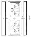
- FIGS. 1A and 1Billustrate a mobile telephone system
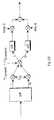
- FIG. 2Ashows a transmitter and a receiver of a mobile telephone system
- FIG. 2Billustrates spreading and modulation in a transmitter
- FIG. 2Cillustrates the solution of the invention to a combined descrambling, decoding and demodulation block of the receiver of FIG. 2A;
- FIG. 3illustrates channels of a mobile telephone system positioned in a frame
- FIG. 4illustrates the structure of user equipment in a simplified manner.
- the inventionmay be applied to mobile telephone systems of different kinds, using Code Division Multiple Access (CDMA) method.
- CDMACode Division Multiple Access
- the exampiesillustrate the use of the invention in a universal mobile telephone system utilizing a direct sequence broadband code division multiple access method; without the invention being restricted to this, however.
- the mobile telephone system IMT-2000 developed by ARIB (Association of Radio Industries and Businesses) in Japan and the Universal Mobile Telephone System (UMTS) to be developed in Europeare systems in accordance with the invention.
- FIG. 1Bcomprises only the blocks that are essential for the description of the invention, but it is obvious to one skilled in the art that a conventional mobile telephone system also comprises other functions and structures, which need not be explained here in more detail.
- the main parts of a mobile telephone systemare a Core Network CN, a UMTS terrestrial radio access network UTRAN and User Equipment UE.
- the interface between CN and UTRANis called lu and the air interface between UTRAN and UE is called Uu.
- UTRANcomprises Radio Network Subsystems RNS.
- the interface between the RNSsis called lur.
- An RNScomprises a Radio Network Controller RNC and one or more nodes B.
- the interface between RNC and Bis called lub.
- the coverage area of node B, i.e. a cell,is designated C in FIG. 1 B.
- FIG. 1AThe description of FIG. 1A is very abstract, and therefore, it is clarified in FIG. 1B by showing which part of the GSM system approximately corresponds to which part of the UMTS. It shall be noted that the mapping presented is not in any way binding, but indicative, because the responsibilities and functions of the various parts of the UMTS are still under development.
- a circuit-switched connectioncan be established from user equipment UE to a telephone 100 connected to a Public Switched Telephone Network (PSTN) 102 .
- PSTNPublic Switched Telephone Network
- User equipment UEcan be for instance a fixed terminal, a terminal positioned in a vehicle or a portable terminal.
- the radio network infrastructure UTRANcomprises radio network sub-systems RNS, i.e. base station systems.
- a radio network subsystem RNScomprises a radio network controller RNC, i.e. a base station controller, and at least one node B, i.e. a base station, controlled by that controller.
- a base station Bcomprises a multiplexer 114 , transceivers 116 and a control unit 118 controlling the operation of the transceivers 114 and the multiplexer 116 .
- Traffic and control channels used by a plurality of transceivers 114are positioned on a transmission link lub by the multiplexer 116 .
- the base station controller RNScomprises a switching network 110 and a control unit 112 .
- the switching network 110is used for connecting speech and data and for combining signalling circuits.
- the base station system constituted of the base station B and the base station controller RNCadditionally comprises a transcoder 108 .
- the division of tasks between the base station controller RNC and the base station B and the physical structure thereofmay vary as per implementation.
- the base station Btypically attends to the implementation of the radio path in the above-described manner.
- the base station controller RNCtypically controls things as follows: radio resources, handover between cells, power control, timing and synchronization, paging of user equipment.
- the transcoder 108is generally situated as close to a mobile phone exchange 106 as possible, because speech then can be transmitted in the form of a mobile phone system between the transcoder 108 and the base station controller RNC by saving transmission capacity.
- the transcoder 108converts the various digital speech coding forms between the public switched telephone network and the radio telephone network into compatible, for instance from a 64 kbit/s form of a fixed network to another (for instance 13 kbit/s) form of the cellular radio network and vice versa.
- the devices requiredare not described here any further, but it can be stated that no other data than speech is converted by the transcoder 108 .
- the control unit 112performs call control and mobility management, collects statistic data and performs signalling.
- a core network CNis constituted of an infrastructure belonging to a mobile telephone system outside the UTRAN.
- FIG. 1Billustrates the mobile phone exchange 106 and a gateway mobile phone exchange 104 , attending to the connections of the mobile phone system to the outside world, here to the public switched telephone network 102 .
- FIG. 4shows an example of the structure of user equipment UE.
- the substantial parts of user equipment UEare: an interface 404 for an antenna 402 of user equipment, a transceiver 406 , a control part 410 of user equipment and an interface 412 for a battery 414 .
- a user interfacegenerally comprises a display 400 , a keyboard 408 , a microphone 416 and a loud-speaker 418 .
- User equipmentmay be for instance a portable mobile phone, a phone to be positioned in a car, a terminal of wireless local loop or data transmission equipment integrated into a computer.
- FIG. 2Aillustrates the function of a pair of radio transceivers.
- a radio transmittermay be located in a node B or in user equipment UE and a radio receiver in user equipment UE or in the node B.
- FIG. 2Ashows the essential functions of a radio transmitter.
- Various services to be located on a physical channelare for instance speech, data, moving or stopped video image and control channels of the system.
- the figureillustrates control channel and data processing.
- the various servicesrequire various source coding means; speech, for instance, requires a speech codec.
- the source coding meansare not shown in FIG. 2A, however.
- Pilot bits used by the receiver for channel estimationare also located on the control channel 214 .
- User data 200are located on the data channel.
- Channel codingcomprises for instance different block codes, an example of them being Cyclic Redundancy Check (CRC).
- CRCCyclic Redundancy Check
- convolution coding and its various modifications, such as punctured convolution coding or turbo codingare typically used.
- Said pilot bitsare not channel coded, however, because the intention is to find out the signal distortions caused by the channel.
- interleaver 204 A, 204 BAfter the various channels have been channel coded, they are interleaved in an interleaver 204 A, 204 B.
- the aim of interleavingis to facilitate error correction.
- the bits of the various servicesare scrambled together in a predetermined way, whereby an instantaneous fading on the radio path alone does not necessarily make the transmitted information unfit for identification.
- the interleaved bitsare spread by a spreading code in blocks 206 A, 206 B.
- the chips obtainedare then scrambled by a scrambling code and modulated in block 208 , the operation of which is described in more detail in FIG. 2 B. In this way, the separate signals are combined in block 208 to be transmitted via the same transmitter.
- radio frequency parts 210which may comprise different power amplifiers and bandwidth restricting filters. Regulation of a closed loop used for transmission power control generally controls a transmission power control amplifier located in this block. An analog radio signal is then sent via the antenna 202 to the radio path Uu.
- the lower part of FIG. 2Aillustrates the essential functions of a radio receiver.
- the radio receiveris typically a RAKE receiver.
- An analog radio frequency signalis received from the radio path Uu by an antenna 232 .
- the signalis brought to radio frequency parts 230 comprising a filter, which prevents frequencies outside the desired frequency band.
- the signalis converted in block 228 to an intermediate frequency or directly to baseband, in which form the signal is sampled and quantized. Because the signal is a multipath propagated signal, the intention is to combine the signal components propagated along different paths in block 228 , the block comprising the actual RAKE fingers of the receiver according to the prior art technique. Block 228 is described in more detail in FIG. 2 C.
- the obtained physical channelis then deinterleaved in a deinterleaver 226 .
- the deinterleaved physical channelis divided into data streams of different channels in a demultiplexer 224 .
- Each channelis brought to a separate channel decoding block 222 A, 222 B, where the channel coding used for a transmission, such as block coding and convolution coding, is decoded.
- Convolution codingis decoded preferably by a Viterbi decoder.
- Each transmitted channel 220 A, 220 Bcan then be brought to be further processed, as needed, for instance data 220 is brought to a computer 122 connected to user equipment UE.
- the control channels of the systemare brought to a control part 236 of the radio receiver.
- FIG. 2Billustrates in more detail how a channel is spread by a spreading code and modulated.
- a bit stream of the channelcomes to block S/P, where each two-bit sequence is converted from series form to parallel form, which means that one bit is brought to branch I of the signal and the other one to branch Q of the signal.
- the signal branches I and Qare multiplied by a spreading code c ch , whereby a relatively narrow-band information is spread to a wide frequency band.
- Each branchcan have the same or a different spreading code.
- Each connection Uuhas a separate spreading code or separate spreading codes, by which the receiver identifies the transmissions intended for it.
- the signalis scrambled by multiplying it by a scrambling code c l scramb +j c Q scramb , being separate for each transmitter.
- the pulse form of the obtained signalis filtered by filters p(t).
- the signalis modulated to a radio frequency carrier by multiplying its separate branches shifted from each other by 90 degrees, the branches thus obtained are combined to one carrier ready to be sent to the radio path Uu, excluding possible filterings and power amplifications.
- the modulation mode describedis Quadrature Phase Shift Keying QPSK.
- time multiplexingcan also be used, where data and control channels are positioned sequentially on time axis. However, the time difference between the channels is then so small that an interference estimated from the control channel can be assumed to be the same also on the data channel.
- the spreading factor two hundred and fifty sixcorresponds to the transmission speed of thirty two kilobits per second, and respectively, the highest practical transmission speed is achieved by spreading factor four, whereby the data transmission speed is two thousand forty eight kilobits per second.
- the transmission speed on the channelvaries stepwise 32, 64,128, 256, 512,1024 and 2048 kbit/s, while the spreading factor varies 256, 128, 64, 32, 16, 8 and 4, respectively.
- the data transmission speed at the user's disposaldepends on the channel coding used.
- the spreading factorinforms the length of the spreading code.
- the spreading code corresponding to the spreading factor oneis (1).
- the spreading factor twohas two mutually orthogonal spreading codes (1, 1) and (1, ⁇ 1).
- the spreading factor fourhas four mutually orthogonal spreading codes: below an upper level spreading code (1, 1), there are spreading codes (1, 1, 1, 1) and (1, 1, ⁇ 1, ⁇ 1), and below another upper level spreading code (1, ⁇ 1), there are spreading codes (1, ⁇ 1, 1, ⁇ 1) and (1, ⁇ 1, ⁇ 1, 1).
- the formation of spreading codesis continued in this way when propagating to lower levels of a code tree.
- the spreading codes of a given levelare always mutually orthogonal.
- a spreading code of a given levelis orthogonal with all the spreading codes of another spreading code of the same level, which are derived from that other spreading code to next levels.
- one symbolis multiplied by a spreading code, whereby the data spreads over the frequency band to be used.
- a spreading codeFor instance, when the spreading code 256 is used, one symbol is represented by 256 chips. Respectively, when the spreading code 16 is used, one symbol is represented by 16 chips.
- FIG. 3shows an example of which kind of frame structure can be used on a physical channel.
- Frames 340 A, 340 B, 340 C, 340 Dare numbered consecutively from one to seventy two and they form a 720 milliseconds long superframe.
- the length of one frame 340 Cis 10 milliseconds.
- the frame 340 Cis divided into sixteen slots 330 A, 330 B, 330 C, 330 D.
- the length of one slot 330 Cis 0.625 milliseconds.
- One slot 330 Ccorresponds typically to one power control period, during which the power is controlled for instance by one decibel upwards or downwards.
- the physical channelsare divided into two different types: Dedicated Physical Data Channels (DPDCH) 310 and Dedicated Physical Control Channels (DPCCH) 312 .
- the dedicated physical data channels 310are used for transporting data 306 generated in layer two of Open Systems Interconnection (OSI) and above it, i.e. dedicated traffic channels, mainly.
- the dedicated physical control channels 312transport control information generated in layer one of OSI.
- the control informationcomprises: a pilot part, i.e. pilot bits, 300 to be utilized for channel estimation, Transmit Power Control (TPC) commands 302 and, optionally, a Transport Format Indicator (TFI) 304 .
- TPCTransmit Power Control
- TFITransport Format Indicator
- the transport format indicator 304tells the receiver the transmission speed used at that moment by each dedicated physical data channel in the uplink direction.
- the dedicated physical data channels 310 and the dedicated physical control channels 312are time-multiplexed into the same slot 330 C in the downlink direction.
- QPSKQuadrature Phase Shift Keying
- FIG. 2Cis examined, the figure illustrating in more detail the combined descrambling, decoding and demodulating block 228 of the receiver, shown in FIG. 2 A.
- Descramblingis not described, however, because it is of no relevance for the invention.
- a desired radio signalsent to the radio path Uu, multipath propagates on an occasionally fading channel 250 .
- additive zero mean white gaussian noise 254is combined with the signal.
- interfering signals, also multipath propagating on an occasionally fading channel 252are combined with the signal.
- a signal to be received from the radio path Uucontains, besides the wanted signal, also both noise and interference.
- the signalis received by using at least two separate antenna branches 232 A, 232 B.
- the branches 232 A, 232 Bmay form an antenna array to provide antenna gain, the separate antennas being relatively close to each other, at a distance of half a wavelength, for instance.
- Another possibilityis that the branches 232 A, 232 B are diversity branches, the separate antennas being relatively far from each other, at a distance of 10 to 20 wavelengths, for instance.
- the diversitycan be implemented as space or polarization diversity.
- FIG. 2Cillustrates the use of space diversity, the branches 232 A, 232 B being implemented as an adaptive antenna.
- the adaptive antennais implemented by antennas 232 A, 232 B positioned far enough from each other, via which antennas the multipath propagated signal is received.
- the number of antennasmay be L.
- the figureillustrates only two antennas, the first antenna 232 A and the Lth antenna 232 B.
- the two points between the antennasrepresent the existing antennas, not described for the sake of clarity, however.
- the number of antennasvaries between two and eight.
- signals received via the separate antenna branches 232 A, 232 Bare weighted in such a way that the influence of noise and interference can be minimized.
- polarization diversitywhereby a signal is received by cross-polarized antennas.
- hybridsare possible, which means that both space and polarization diversity may be used simultaneously.
- patch antennacan be a plate of about a square inch in size, the plate having cross polarization planes.
- user equipment positioned in a vehiclewhere an implementation of space diversity also is relatively easy.
- a signal received from all L antenna branches 232 A, 232 Bis brought via radio frequency parts (not shown in FIG. 2C) to a delay estimator 260 connected to the antenna branch 232 A, 232 B.
- the delay estimator 260the delays of the best audible multipath propagated signal components are searched for.
- a RAKE finger 270 A, 270 Bis allocated for processing the found multipath propagated signal components.
- the delay estimator 260informs each RAKE branch 270 A, 270 B of the found delay.
- the delay estimator 260comprises a matched filter 262 A, 262 B for each antenna branch 232 A, 232 B.
- the number of matched filters 262 A, 262 Bis also L.
- a predetermined number of parallel correlation calculationsis performed for the received radio signal by different delays in order to estimate the delays of the multipath propagated signal components.
- the spread pilot part contained in the received radio signalis despread by a known spreading code using a predetermined delay.
- an allocator 264 situated in the delay estimatorselects at least one delay, by which a multipath propagated signal component is received.
- the allocatorallocates a RAKE finger 270 A, 270 B for processing the found signal component by informing the RAKE finger of the found delay.
- the correlation results of each matched filter 262 A, 262 Bare typically combined in the allocator 264 . If the correlation is high, a delay is found that represents the delay of the multipath propagated signal component of the radio signal coming to the antenna branch 232 A, 232 B in question.
- the strongest multipath componentshave the same code phase at all antennas, which is due to the vicinity of the antennas and to the fact that radio signals propagate at the speed of light.
- a predetermined number of RAKE fingers 270 A, 270 Bis allocated and/or a number required for delays exceeding a predetermined threshold value at correlation calculation.
- a limiting factorwill be the maximum number of the used RAKE fingers 270 A, 270 B.
- the number of allocated RAKE fingers 270 A, 270 Bis indicated by the letter N.
- the number of signal componentsdepends on radio conditions and, for instance, on terrain shape and buildings causing reflections. In the most cases, the smallest delay by which multipath propagated signal components are searched for is one chip.
- the RAKE finger 270 A, 270 Bprocesses one multipath propagated signal component by a given code delay.
- the RAKE finger 270 A, 270 Bcomprises a channel estimator 272 , by which a channel impulse response of a multipath propagated signal component, included in a radio signal and found by means of a known pilot part, i.e. practically complex impulse response taps of the channel, are generated.
- the RAKE finger 270 A, 270 Bcomprises an interference estimator 272 , by which an interference signal, included in a radio signal of each antenna branch 232 A, 232 B and consisting of interference and noise, is generated by subtracting from the received radio signal a regenerated wanted radio signal.
- the regenerated wanted radio signalis obtained by means of the known pilot part included in the radio signal and by means of the estimated impulse response of the channel.
- FIG. 2Cillustrate the processing of the pilot part 274 A included in the radio signal and the processing of the data part 274 B included in the radio signal.
- the RAKE finger 270 A, 270 Bcomprises a despreader 276 A, 276 B, connected to each antenna branch 232 A, 232 B and despreading the spread pilot part 274 A included in the multipath propagated signal component, by using a known spreading code by a delay informed by the delay estimator 260 .
- the RAKE finger 270 A, 270 Bcomprises a despreader 276 C, 276 D, connected to each antenna branch 232 A, 232 B and despreading the spread data part 274 B included in the multipath propagated signal component, by using a known spreading code by a delay informed by the delay estimator 260 .
- the data part or the pilot part of the signal componentis multiplied by a complex conjugate of the spreading code in the right phase.
- the delay estimator 260allocates N RAKE fingers 270 A, 270 B, for the best audible signal components.
- NIn each RAKE finger 270 A, 270 B, L antenna branches 232 A, 232 B, are processed. Both the pilot part of the radio signal and the data part of the radio signal are processed separately.
- the number Nmay vary depending on circumstances, or a threshold value may be set for the level of the multipath propagated signal component. If this threshold value is exceeded, said RAKE finger 270 A, 270 B is noted and the reception continues. Consequently, searching for timing is a dynamic process, and so is the allocation of the RAKE fingers 270 A, 270 B to be combined.
- a weighting coefficient part 272 in the RAKE finger 270 A, 270 Bforms weighting coefficients maximizing the signal-to-interference-and-noise ratio (SINR) for each antenna branch 232 A, 232 B. This can be made for instance by multiplying an inverse matrix of a covariance matrix of an interference signal, consisting of interference and noise of the antenna branches 232 A, 233 B, by an estimated impulse response of the channel.
- the weighting coefficientsare complex.
- the pilot part 274 A despread by the despreader 276 A, 276 B in each antenna branch 232 A, 232 Bis multiplied by the obtained weighting coefficients by using a multiplier 284 A, 284 B located in the RAKE finger 270 A, 270 B.
- the data part 274 B despread by the despreader 276 C, 276 D in each antenna branch 232 A, 232 Bis multiplied by the obtained weighting coefficients by using a multiplier 284 C, 284 D. Accordingly, the signal components including the pilot part and the signal components including the data part are multiplied by the same weighting coefficients separately.
- An antenna branch summer 278 Apositioned last in the RAKE finger 270 A, 270 B, combines the despread pilot parts 274 A, received via the separate antenna branches 232 A, 232 B and multiplied by a weighting coefficient, to one pilot signal.
- an antenna branch summer 278 Bcombines the despread data parts 274 B, received via the separate antenna branches 232 A, 232 B and multiplied by a weighting coefficient, to one data signal.
- the RAKE receiveradditionally comprises a RAKE finger summer 280 B combining the data signals of the RAKE fingers 270 A, 270 B functioning by different delays to a sum data signal representing the received bits.
- the data bitsare then brought according to FIG. 2A from block 228 to block 226 to be deinterleaved.
- the receiver presentedis suitable for use both at a base station and at user equipment. This means that both I/Q multiplexing and time multiplexing of data channel and control channel are possible.
- the antenna branch summer 278 A, 278 B and the RAKE finger summer 280 A, 280 Bthere may be a real part 278 A, 278 B, removing from the combined signal of each antenna branch its imaginary part, because imaginary part is an error term generated at channel estimation.
- the RAKE receivercomprises a RAKE finger summer 280 A combining the pilot signals of the RAKE fingers 270 A, 270 B, functioning by different delays, to a sum pilot signal representing the received pilot bits.
- This sum pilot signalcan be brought to an estimator 282 of the signal-to-inference ratio, estimating the signal-to-interference ratio of said channel.
- the power control of a closed loopcan be controlled by the obtained signal-to-interference ratio of said channel. This is illustrated in block 282 of FIG. 2C by the text TPC (Transmission Power Control).
- the inventionis implemented preferably by software, at least part of the functions included in block 228 being changed to a software to be performed by a processor.
- the delay estimator 260 requiring a high calculation capacityis preferably implemented as an Application Specific Integrated Circuit (ASIC).
- ASICApplication Specific Integrated Circuit
- the other functions included in block 228can also be implemented by device solutions offering the needed functionality, such as an ASIC or a discrete logic.
- a method of calculating weighting coefficients maximizing the SINRis presented next, assuming that the impulse response h of the channel and the covariance matrix R uu of interference and noise are known. Subsequently, a method of estimating h and R uu by means of known pilot bits included in a signal is presented.
- the presentationis a complex baseband signal model on symbol level for processing the signal. In the presentation, the bold face terms illustrate a vertical vector or a matrix.
- SOIMultipath propagated Signals Of Interest
- the signal received from the L antennasis indicated by a vector r n .
- An information symbol of the Mth user out of an alphabet of size Mis indicated by the term s m .
- the Gaussian assumption for the despread MAIis valid for a great number of spreading factors having different lengths.
- each symbol periodis discretized into K samples, whereby the vector r n can be presented in the form:
- the Gaussian distributed interference variables u n [k] and u[k]are mutually uncorrelated across sampling instants and also across the different multipath propagated components of SOI. Then:
- the optimal demodulationinvolves the maximization of the log likelihood function (
- the outputs of the RAKE fingersare summed, i.e. combined, and a correlation detector is applied to determine for the symbol s m a value enabling the largest symbol correlation metric.
- the receivercan be constructed in such a way that the interference elimination method can be changed according to the circumstances between the MRC and IRC.
- LMSLeast Mean Square
- RLSRecursive Least Square
- I/Q multiplexingis used in the uplink direction, the data channel being multiplexed to the branch I and the control channel to the branch Q.
- the control channelalso comprises a previously known pilot part. Both channels can be separated from each other by despreading with orthogonal spreading codes.
- the symbol-level signal modelis obtained from equation 1, by writing it separately for each part, I and Q, using BPSK symbols s m ⁇ 1,1 ⁇ . It is further assumed that the index k now refers to the bit index of the symbol sequence. K bits of DPCCH are collected into one slot.
- Adjacent Channel PowerACP
- the adjacent frequency bandmay be the WCDMA frequency band adjacent to said operator, the WCDMA frequency band of another operator or a frequency band of some other system, for instance GSM system.
- the problemmay cause blocking in the cell in the uplink direction. For instance, let us assume that a high efficiency GSM transmitter causes ACP to a RAKE receiver operating at a high data speed, i.e. at a low spreading ratio, on a 5 MHz frequency band, for instance.
- the ACP(as interference in general) must be above the noise level so that it can be eliminated.
- an interference signal generated by the interference estimator 272then comprises interference caused by the adjacent frequency band of the wanted channel, i.e. adjacent channel power, the detrimental effect of which can thus be eliminated. A shrinking of the cell on account of ACP can thus be prevented.
Landscapes
- Engineering & Computer Science (AREA)
- Computer Networks & Wireless Communication (AREA)
- Signal Processing (AREA)
- Mobile Radio Communication Systems (AREA)
- Noise Elimination (AREA)
- Ultra Sonic Daignosis Equipment (AREA)
- Lock And Its Accessories (AREA)
Abstract
Description


Claims (13)
Applications Claiming Priority (3)
| Application Number | Priority Date | Filing Date | Title |
|---|---|---|---|
| FI981977AFI106897B (en) | 1998-09-14 | 1998-09-14 | RAKE receiver |
| FI981977 | 1998-09-14 | ||
| PCT/FI1999/000749WO2000016494A1 (en) | 1998-09-14 | 1999-09-14 | Rake receiver |
Related Parent Applications (1)
| Application Number | Title | Priority Date | Filing Date |
|---|---|---|---|
| PCT/FI1999/000749ContinuationWO2000016494A1 (en) | 1998-09-14 | 1999-09-14 | Rake receiver |
Publications (1)
| Publication Number | Publication Date |
|---|---|
| US6215814B1true US6215814B1 (en) | 2001-04-10 |
Family
ID=8552484
Family Applications (1)
| Application Number | Title | Priority Date | Filing Date |
|---|---|---|---|
| US09/571,138Expired - LifetimeUS6215814B1 (en) | 1998-09-14 | 2000-05-15 | RAKE receiver |
Country Status (11)
| Country | Link |
|---|---|
| US (1) | US6215814B1 (en) |
| EP (1) | EP1040591B1 (en) |
| JP (1) | JP2002525905A (en) |
| CN (1) | CN1131600C (en) |
| AT (1) | ATE321379T1 (en) |
| AU (1) | AU5749199A (en) |
| DE (1) | DE69930527T2 (en) |
| ES (1) | ES2258853T3 (en) |
| FI (1) | FI106897B (en) |
| NO (1) | NO20002221L (en) |
| WO (1) | WO2000016494A1 (en) |
Cited By (79)
| Publication number | Priority date | Publication date | Assignee | Title |
|---|---|---|---|---|
| US20010038665A1 (en)* | 2000-03-03 | 2001-11-08 | Jens Baltersee | Method and rake receiver for phasor estimation in communication systems |
| WO2001091317A1 (en)* | 2000-05-24 | 2001-11-29 | Nokia Corporation | Rake receiver and method of receiving desired signal |
| US20020031168A1 (en)* | 2000-07-08 | 2002-03-14 | Samsung Electronics Co., Ltd | Method and apparatus for flexible data rate matching by symbol insertion for a data communication system |
| US20020037028A1 (en)* | 2000-01-14 | 2002-03-28 | Jens Baltersee | Method and rake receiver for code-tracking in communication systems |
| WO2002013491A3 (en)* | 2000-08-04 | 2002-04-25 | Dspc Tech Ltd | A family of linear multi-user detectors (muds) |
| US20020054620A1 (en)* | 2000-08-22 | 2002-05-09 | Nec Corporation | Paging mode control method and apparatus |
| US20020067761A1 (en)* | 2000-12-01 | 2002-06-06 | Ning Kong | Method and system for canceling multiple access interference in CDMA wireless communication system |
| US20020126745A1 (en)* | 2001-03-12 | 2002-09-12 | Motorola, Inc | Signal combining within a communication system |
| US20020141367A1 (en)* | 2001-04-03 | 2002-10-03 | Samsung Electronics Co., Ltd. | Method of transmitting control data in CDMA mobile communication system |
| EP1253434A1 (en)* | 2001-04-27 | 2002-10-30 | Mitsubishi Electric Information Technology Centre Europe B.V. | Method for estimating a direction of arrival |
| US20020164963A1 (en)* | 2001-04-09 | 2002-11-07 | Tehrani Ardavan Maleki | Method and system for providing antenna diversity |
| US20030035468A1 (en)* | 2001-05-17 | 2003-02-20 | Corbaton Ivan Jesus Fernandez | System and method for adjusting combiner weights using an adaptive algorithm in wireless communications system |
| US6529545B2 (en)* | 1999-11-26 | 2003-03-04 | Nokia Networks Oy | Rake receiver |
| US20030053525A1 (en)* | 2001-09-10 | 2003-03-20 | Innov-Ics | Method for 2D antenna rake combining in a code division multiplication access system |
| US20030081659A1 (en)* | 2000-02-11 | 2003-05-01 | The Regents Of The University Of California | Method and apparatus for resolving multipath components for wireless location finding |
| US20030112855A1 (en)* | 2001-12-19 | 2003-06-19 | D.S.P.C. Technologies Ltd | Method and WCDMA receiver for high-rate and low-rate physical channel reception |
| US6584331B2 (en) | 2001-10-09 | 2003-06-24 | Nokia Corporation | Use of received signal strength indicator (RSSI) and global positioning system (GPS) to reduce power consumption in mobile station |
| US20030126539A1 (en)* | 2001-12-31 | 2003-07-03 | Bysted Tommy Kristensen | Transport channel interleaving |
| US20030137956A1 (en)* | 2002-01-15 | 2003-07-24 | Salehi Jawad Ahmed | Method and system for multiple-shift code acquisition of optical orthogonal codes in optical CDMA systems |
| WO2003061380A2 (en) | 2001-05-17 | 2003-07-31 | Qualcomm Incorporated | System and method for received signal prediction in wireless communications system |
| WO2003069790A3 (en)* | 2002-02-13 | 2003-10-02 | Pa Consulting Services | Cdma receiver with controllable functions |
| US6654922B1 (en)* | 2000-04-10 | 2003-11-25 | Nokia Corporation | Method and apparatus for declaring correctness of reception of channels for use in a mobile telecommunications system |
| US20030235238A1 (en)* | 2002-06-24 | 2003-12-25 | Comsys Communication & Signal Processing Ltd. | Multipath channel tap delay estimation in a CDMA spread spectrum receiver |
| US6674740B1 (en)* | 1998-08-20 | 2004-01-06 | France Telecom | Iterative rake receiver and corresponding reception process |
| US6683861B1 (en)* | 1999-06-02 | 2004-01-27 | Nec Corporation | CDMA mobile communication system, searcher circuit and communication method |
| US20040042532A1 (en)* | 2000-12-22 | 2004-03-04 | Atte Artamo | Measuring method, and receiver |
| WO2004045117A1 (en) | 2002-11-12 | 2004-05-27 | Zyray Wireless, Inc. | Method and apparatus for rake combining based upon signal to interference noise ratio |
| US20040121780A1 (en)* | 2001-04-20 | 2004-06-24 | Markus Nasshan | Method and device for transmitting data of a subscriber-specific control channel in a radio system |
| US20040127230A1 (en)* | 2002-12-27 | 2004-07-01 | David Bevan | Angle of arrival estimation in a wireless telecommunications network |
| US20040132419A1 (en)* | 2002-09-27 | 2004-07-08 | Steven Fluxman | Rake receiver having several fingers and method of processing an incident signal therein |
| US6765969B1 (en)* | 1999-09-01 | 2004-07-20 | Motorola, Inc. | Method and device for multi-user channel estimation |
| US6765951B2 (en)* | 1999-07-15 | 2004-07-20 | Infineon Technologies Ag | Method for estimating the channel impulse response of a mobile radio channel |
| US6771693B2 (en) | 2001-12-27 | 2004-08-03 | Interdigital Technology Corporation | Enhanced rake structure |
| US20040185787A1 (en)* | 2003-03-03 | 2004-09-23 | Andreas Molisch | Estimating channel impulse response and equalizer coefficients in UWB communication systems |
| US20040247061A1 (en)* | 2003-06-05 | 2004-12-09 | Tadashi Matsumoto | Data processing method, receiver and network element for executing a turbo principle |
| US20050053121A1 (en)* | 2001-12-06 | 2005-03-10 | Ismail Lakkis | Ultra-wideband communication apparatus and methods |
| US20050053165A1 (en)* | 2001-12-06 | 2005-03-10 | Ismail Lakkis | Ultra-wideband communication apparatus and methods |
| KR100475384B1 (en)* | 2002-04-24 | 2005-03-10 | 엘지전자 주식회사 | Rake receiver and signal processing method of the same |
| US20050058180A1 (en)* | 2001-12-06 | 2005-03-17 | Ismail Lakkis | Ultra-wideband communication apparatus and methods |
| US20050069020A1 (en)* | 2001-12-06 | 2005-03-31 | Ismail Lakkis | Ultra-wideband communication apparatus and methods |
| US6879576B1 (en)* | 2000-09-06 | 2005-04-12 | Qualcomm Incorporated | Method and apparatus for processing a physical channel with partial transport format information |
| US20050101279A1 (en)* | 2002-09-23 | 2005-05-12 | Lee Kuo H. | Receiving method and receiver |
| US20050111526A1 (en)* | 2003-10-02 | 2005-05-26 | Attila Bilgic | Determination and selection of transmission paths as a function of the operating situation for setting up rake fingers for rake receiver units in mobile communication terminals |
| US20050152295A1 (en)* | 2004-01-14 | 2005-07-14 | Interdigital Technology Corporation | Telescoping window based equalization |
| US20050152483A1 (en)* | 2001-12-06 | 2005-07-14 | Ismail Lakkis | Systems and methods for implementing path diversity in a wireless communication network |
| US6925127B1 (en)* | 1997-07-22 | 2005-08-02 | Ericsson Inc. | Method and apparatus for subtracting multiple rays of multiple interfering received signals |
| US20050180492A1 (en)* | 2000-10-06 | 2005-08-18 | Dent Paul W. | Method for subtracting multiple rays of multiple interfering received signals |
| US20050233710A1 (en)* | 2001-12-06 | 2005-10-20 | Ismail Lakkis | High data rate transmitter and receiver |
| US20060023775A1 (en)* | 2004-08-02 | 2006-02-02 | Nokia Corporation | Method and apparatus to estimate signal to interference plus noise ratio (SINR) in a multiple antenna receiver |
| US7038589B2 (en)* | 2002-11-03 | 2006-05-02 | Schmidt Dominik J | Systems and methods for tracking an object |
| US20060098719A1 (en)* | 2000-01-14 | 2006-05-11 | Jens Baltersee | Adaptive code-tracking receiver for direct-sequence code-division multiple access (CDMA) communications over multipath fading channels and method for signal processing in a rake receiver |
| US7099380B1 (en) | 2001-11-16 | 2006-08-29 | Marvell International Ltd. | Apparatus for antenna diversity for wireless communication and method thereof |
| USRE39275E1 (en)* | 1999-07-12 | 2006-09-12 | Electronics And Telecommunications Research Institute | Hardware-efficient demodulator for CDMA adaptive antenna array systems |
| US20060203894A1 (en)* | 2005-03-10 | 2006-09-14 | Nokia Corporation | Method and device for impulse response measurement |
| US20060251155A1 (en)* | 2005-05-03 | 2006-11-09 | Gongyu Zhou | Rake receiver with time-shared fingers |
| US20060274817A1 (en)* | 2000-09-25 | 2006-12-07 | Lakkis Ismail A | Method and apparatus for wireless communications |
| US7177345B2 (en) | 2001-12-24 | 2007-02-13 | Electronics And Telecommunication Research Institute | Demodulating device and method for W-CDMA base station |
| US20070098095A1 (en)* | 2005-10-12 | 2007-05-03 | Samsung Electronics Co., Ltd. | Method and apparatus for transmitting data in a communication system |
| US20080008234A1 (en)* | 2001-12-06 | 2008-01-10 | Ismail Lakkis | Systems and methods for equalization of received signals in a wireless communication network |
| US20080043654A1 (en)* | 2001-12-06 | 2008-02-21 | Lakkis Ismail A | Systems and methods for wireless communication over a wide bandwidth channel using a plurality of sub-channels |
| US20080056333A1 (en)* | 2001-12-06 | 2008-03-06 | Ismail Lakkis | Ultra-wideband communication apparatus and methods |
| US20080056186A1 (en)* | 2001-12-06 | 2008-03-06 | Ismail Lakkis | Ultra-wideband communication systems and methods |
| US20080056332A1 (en)* | 2001-12-06 | 2008-03-06 | Ismail Lakkis | Ultra-wideband communication systems and methods |
| US20080109696A1 (en)* | 2001-12-06 | 2008-05-08 | Ismail Lakkis | Systems and methods for forward error correction in a wireless communication network |
| US20080107199A1 (en)* | 2001-12-06 | 2008-05-08 | Ismail Lakkis | Systems and methods for recovering bandwidth in a wireless communication network |
| US7403576B2 (en) | 2001-12-06 | 2008-07-22 | Pulse-Link, Inc. | Systems and methods for receiving data in a wireless communication network |
| US20080225963A1 (en)* | 2000-09-25 | 2008-09-18 | Ismail Lakkis | Ultra-wideband communication systems and methods |
| US7437135B2 (en) | 2003-10-30 | 2008-10-14 | Interdigital Technology Corporation | Joint channel equalizer interference canceller advanced receiver |
| KR100867973B1 (en) | 2004-08-02 | 2008-11-10 | 노키아 코포레이션 | Method, apparatus and computer readable recording medium for estimating signal to interference plus noise ratio (SIINR) in a multi-antenna receiver |
| US20090003415A1 (en)* | 2007-06-28 | 2009-01-01 | Sunplus Mmobile Inc. | Rake receiver and de-spreading method thereof |
| US20090238247A1 (en)* | 2006-05-29 | 2009-09-24 | Nxp B.V. | Low-cost and low-complexity inner communication receiver for receive diversity |
| US20090238244A1 (en)* | 2008-03-20 | 2009-09-24 | Mcdowell Anthony T | Method for operating a rake receiver |
| US20090290618A1 (en)* | 2008-05-21 | 2009-11-26 | Qualcomm Incorporated | Methods and systems for hybrid mimo schemes in ofdm/a systems |
| US20100040116A1 (en)* | 2008-02-28 | 2010-02-18 | Nokia Corporation | Dynamic Combining Threshold for a Rake Receiver |
| US7903613B2 (en)* | 1995-06-30 | 2011-03-08 | Interdigital Technology Corporation | Code division multiple access (CDMA) communication system |
| US7929498B2 (en) | 1995-06-30 | 2011-04-19 | Interdigital Technology Corporation | Adaptive forward power control and adaptive reverse power control for spread-spectrum communications |
| US20120115520A1 (en)* | 2009-04-22 | 2012-05-10 | Roessel Sabine | Selective Interference Rejection Combining |
| US8737363B2 (en) | 1995-06-30 | 2014-05-27 | Interdigital Technology Corporation | Code division multiple access (CDMA) communication system |
| US12362796B2 (en) | 2019-12-12 | 2025-07-15 | Viasat, Inc. | Satellite communications using spread signals |
Families Citing this family (15)
| Publication number | Priority date | Publication date | Assignee | Title |
|---|---|---|---|---|
| JP3424659B2 (en)* | 2000-06-02 | 2003-07-07 | 日本電気株式会社 | Multi-beam receiver |
| JP3595493B2 (en) | 2000-07-10 | 2004-12-02 | 三菱電機株式会社 | Wireless receiver |
| KR100576665B1 (en)* | 2000-07-26 | 2006-05-10 | 미쓰비시덴키 가부시키가이샤 | Multi-carrier cdma communication device, multi-carrier cdma transmitting device, and multi-carrier cdma receiving device |
| WO2002017508A2 (en)* | 2000-08-22 | 2002-02-28 | Mitsubishi Denki Kabushiki Kaisha | Digital receiver and method for symbol detection in a spread spectrum signal |
| AU770602B2 (en) | 2000-10-05 | 2004-02-26 | Samsung Electronics Co., Ltd. | TSTD apparatus and method for a TDD CDMA mobile communication system |
| US7769078B2 (en)* | 2000-12-22 | 2010-08-03 | Telefonaktiebolaget Lm Ericsson (Publ) | Apparatus, methods and computer program products for delay selection in a spread-spectrum receiver |
| DE10123334A1 (en)* | 2001-05-14 | 2002-12-05 | Infineon Technologies Ag | RAKE receiver for FDD and TDD mode |
| US7230975B2 (en)* | 2001-08-07 | 2007-06-12 | Qualcomm Incorporated | Adaptive pilot filter for a wireless communication system |
| EP1419605A1 (en)* | 2001-08-23 | 2004-05-19 | Siemens Aktiengesellschaft | Method of improving transmit diversity reliability by including interleaving the transmit data in a single time slot |
| KR20030030590A (en)* | 2001-10-11 | 2003-04-18 | 주식회사 세스텍 | Finger Using Symbol-Rate Weightig in Smart Antenna System, and Its Application for Demodulation Apparatus and Method |
| EP1359684A1 (en)* | 2002-04-30 | 2003-11-05 | Motorola Energy Systems Inc. | Wireless transmission using an adaptive transmit antenna array |
| KR100575932B1 (en)* | 2003-04-23 | 2006-05-02 | 삼성전자주식회사 | Receiving apparatus and method using post-descrambling in code division multiple access mobile communication system |
| CN100364242C (en)* | 2005-09-13 | 2008-01-23 | 浙江华立通信集团有限公司 | Novel high integrated level insertible Rake receiver system |
| US8224314B2 (en)* | 2009-10-07 | 2012-07-17 | Telefonaktiebolaget L M Ericsson (Publ) | Reduced-complexity coordinated multipoint reception |
| CN103516412B (en)* | 2012-06-28 | 2017-03-08 | 联芯科技有限公司 | The multiple-input and multiple-output detection method of receiving data and system |
Citations (8)
| Publication number | Priority date | Publication date | Assignee | Title |
|---|---|---|---|---|
| WO1994028640A1 (en) | 1993-06-02 | 1994-12-08 | Roke Manor Research Limited | Rake receiver combining all the useful multipath components of a spread spectrum signal |
| EP0690588A2 (en)* | 1994-07-01 | 1996-01-03 | Roke Manor Research Limited | RAKE receiver combining all the useful multipath components of a spread spectrum signal |
| US5652765A (en) | 1993-08-06 | 1997-07-29 | Ntt Mobile Communications Network Inc. | Receiver and repeater for spread spectrum communications |
| FR2746233A1 (en) | 1996-03-18 | 1997-09-19 | Motorola Inc | METHOD FOR DETERMINING WEIGHTING COEFFICIENTS IN A CDMA RADIO RECEIVER |
| US5680419A (en) | 1994-08-02 | 1997-10-21 | Ericsson Inc. | Method of and apparatus for interference rejection combining in multi-antenna digital cellular communications systems |
| EP0825727A1 (en) | 1996-08-23 | 1998-02-25 | Ntt Mobile Communications Network Inc. | Rake receiver |
| US5809020A (en)* | 1996-03-18 | 1998-09-15 | Motorola, Inc. | Method for adaptively adjusting weighting coefficients in a cDMA radio receiver |
| US5999560A (en)* | 1997-09-11 | 1999-12-07 | Nec Corporation | Rake reception method for a spread spectrum signal |
- 1998
- 1998-09-14FIFI981977Apatent/FI106897B/enactive
- 1999
- 1999-09-14JPJP2000570913Apatent/JP2002525905A/enactivePending
- 1999-09-14CNCN99801590Apatent/CN1131600C/ennot_activeExpired - Fee Related
- 1999-09-14ESES99944664Tpatent/ES2258853T3/ennot_activeExpired - Lifetime
- 1999-09-14DEDE69930527Tpatent/DE69930527T2/ennot_activeExpired - Lifetime
- 1999-09-14ATAT99944664Tpatent/ATE321379T1/ennot_activeIP Right Cessation
- 1999-09-14AUAU57491/99Apatent/AU5749199A/ennot_activeAbandoned
- 1999-09-14EPEP99944664Apatent/EP1040591B1/ennot_activeExpired - Lifetime
- 1999-09-14WOPCT/FI1999/000749patent/WO2000016494A1/enactiveIP Right Grant
- 2000
- 2000-04-28NONO20002221Apatent/NO20002221L/ennot_activeApplication Discontinuation
- 2000-05-15USUS09/571,138patent/US6215814B1/ennot_activeExpired - Lifetime
Patent Citations (10)
| Publication number | Priority date | Publication date | Assignee | Title |
|---|---|---|---|---|
| WO1994028640A1 (en) | 1993-06-02 | 1994-12-08 | Roke Manor Research Limited | Rake receiver combining all the useful multipath components of a spread spectrum signal |
| US5652765A (en) | 1993-08-06 | 1997-07-29 | Ntt Mobile Communications Network Inc. | Receiver and repeater for spread spectrum communications |
| EP0690588A2 (en)* | 1994-07-01 | 1996-01-03 | Roke Manor Research Limited | RAKE receiver combining all the useful multipath components of a spread spectrum signal |
| US5680419A (en) | 1994-08-02 | 1997-10-21 | Ericsson Inc. | Method of and apparatus for interference rejection combining in multi-antenna digital cellular communications systems |
| FR2746233A1 (en) | 1996-03-18 | 1997-09-19 | Motorola Inc | METHOD FOR DETERMINING WEIGHTING COEFFICIENTS IN A CDMA RADIO RECEIVER |
| GB2311445A (en) | 1996-03-18 | 1997-09-24 | Motorola Inc | Method for determining weighting coefficients in a CDMA radio receiver |
| US5809020A (en)* | 1996-03-18 | 1998-09-15 | Motorola, Inc. | Method for adaptively adjusting weighting coefficients in a cDMA radio receiver |
| EP0825727A1 (en) | 1996-08-23 | 1998-02-25 | Ntt Mobile Communications Network Inc. | Rake receiver |
| US6026115A (en)* | 1996-08-23 | 2000-02-15 | Ntt Mobile Communications Network, Inc. | Rake receiver |
| US5999560A (en)* | 1997-09-11 | 1999-12-07 | Nec Corporation | Rake reception method for a spread spectrum signal |
Non-Patent Citations (2)
| Title |
|---|
| "The ETSI UMTS Terrestrial Radio Access (UTRA) ITU-R RTT Candidate Submission", (Tdoc SMG 2 260/98), May 1998. |
| Copy of International Search Report for PCT/FI99/00749. |
Cited By (152)
| Publication number | Priority date | Publication date | Assignee | Title |
|---|---|---|---|---|
| US8737363B2 (en) | 1995-06-30 | 2014-05-27 | Interdigital Technology Corporation | Code division multiple access (CDMA) communication system |
| US9564963B2 (en) | 1995-06-30 | 2017-02-07 | Interdigital Technology Corporation | Automatic power control system for a code division multiple access (CDMA) communications system |
| US7929498B2 (en) | 1995-06-30 | 2011-04-19 | Interdigital Technology Corporation | Adaptive forward power control and adaptive reverse power control for spread-spectrum communications |
| US7903613B2 (en)* | 1995-06-30 | 2011-03-08 | Interdigital Technology Corporation | Code division multiple access (CDMA) communication system |
| US6925127B1 (en)* | 1997-07-22 | 2005-08-02 | Ericsson Inc. | Method and apparatus for subtracting multiple rays of multiple interfering received signals |
| US6674740B1 (en)* | 1998-08-20 | 2004-01-06 | France Telecom | Iterative rake receiver and corresponding reception process |
| US6683861B1 (en)* | 1999-06-02 | 2004-01-27 | Nec Corporation | CDMA mobile communication system, searcher circuit and communication method |
| USRE39275E1 (en)* | 1999-07-12 | 2006-09-12 | Electronics And Telecommunications Research Institute | Hardware-efficient demodulator for CDMA adaptive antenna array systems |
| US6765951B2 (en)* | 1999-07-15 | 2004-07-20 | Infineon Technologies Ag | Method for estimating the channel impulse response of a mobile radio channel |
| US6765969B1 (en)* | 1999-09-01 | 2004-07-20 | Motorola, Inc. | Method and device for multi-user channel estimation |
| US6529545B2 (en)* | 1999-11-26 | 2003-03-04 | Nokia Networks Oy | Rake receiver |
| US7203220B2 (en) | 2000-01-14 | 2007-04-10 | Agere Systems Inc. | Method and rake receiver for code-tracking in communication systems |
| US7333532B2 (en) | 2000-01-14 | 2008-02-19 | Agere Systems Inc. | Adaptive code-tracking receiver for direct-sequence code-division multiple access (CDMA) communications over multipath fading channels and method for signal processing in a rake receiver |
| US7142585B2 (en) | 2000-01-14 | 2006-11-28 | Agere Systems Inc. | Adaptive code-tracking receiver for direct-sequence code-division multiple access (CDMA) communications over multipath fading channels and method for signal processing in a rake receiver |
| US20060098719A1 (en)* | 2000-01-14 | 2006-05-11 | Jens Baltersee | Adaptive code-tracking receiver for direct-sequence code-division multiple access (CDMA) communications over multipath fading channels and method for signal processing in a rake receiver |
| US20020037028A1 (en)* | 2000-01-14 | 2002-03-28 | Jens Baltersee | Method and rake receiver for code-tracking in communication systems |
| US20030081659A1 (en)* | 2000-02-11 | 2003-05-01 | The Regents Of The University Of California | Method and apparatus for resolving multipath components for wireless location finding |
| US7068742B2 (en)* | 2000-02-11 | 2006-06-27 | The Regents Of The University Of California | Method and apparatus for resolving multipath components for wireless location finding |
| US20010038665A1 (en)* | 2000-03-03 | 2001-11-08 | Jens Baltersee | Method and rake receiver for phasor estimation in communication systems |
| US7167506B2 (en)* | 2000-03-03 | 2007-01-23 | Agere Systems Inc. | Method and rake receiver for phasor estimation in communication systems |
| US6654922B1 (en)* | 2000-04-10 | 2003-11-25 | Nokia Corporation | Method and apparatus for declaring correctness of reception of channels for use in a mobile telecommunications system |
| US6956841B1 (en) | 2000-05-24 | 2005-10-18 | Nokia Networks Oy | Receiver and method of receiving a desired signal |
| WO2001091317A1 (en)* | 2000-05-24 | 2001-11-29 | Nokia Corporation | Rake receiver and method of receiving desired signal |
| US20020031168A1 (en)* | 2000-07-08 | 2002-03-14 | Samsung Electronics Co., Ltd | Method and apparatus for flexible data rate matching by symbol insertion for a data communication system |
| GB2381723A (en)* | 2000-08-04 | 2003-05-07 | Dspc Tech Ltd | A family of linear multi-user detectors (MUDS) |
| US6618433B1 (en)* | 2000-08-04 | 2003-09-09 | Intel Corporation | Family of linear multi-user detectors (MUDs) |
| GB2381723B (en)* | 2000-08-04 | 2004-07-21 | Dspc Tech Ltd | A family of linear multi-user detectors (MUDS) |
| WO2002013491A3 (en)* | 2000-08-04 | 2002-04-25 | Dspc Tech Ltd | A family of linear multi-user detectors (muds) |
| US20020054620A1 (en)* | 2000-08-22 | 2002-05-09 | Nec Corporation | Paging mode control method and apparatus |
| US7003018B2 (en)* | 2000-08-22 | 2006-02-21 | Nec Electronics Corporation | Paging mode control method and apparatus |
| US6879576B1 (en)* | 2000-09-06 | 2005-04-12 | Qualcomm Incorporated | Method and apparatus for processing a physical channel with partial transport format information |
| US20080225963A1 (en)* | 2000-09-25 | 2008-09-18 | Ismail Lakkis | Ultra-wideband communication systems and methods |
| US20060274817A1 (en)* | 2000-09-25 | 2006-12-07 | Lakkis Ismail A | Method and apparatus for wireless communications |
| US20050180492A1 (en)* | 2000-10-06 | 2005-08-18 | Dent Paul W. | Method for subtracting multiple rays of multiple interfering received signals |
| US20020067761A1 (en)* | 2000-12-01 | 2002-06-06 | Ning Kong | Method and system for canceling multiple access interference in CDMA wireless communication system |
| US6882678B2 (en)* | 2000-12-01 | 2005-04-19 | Ning Kong | Method and system for canceling multiple access interference in CDMA wireless communication system |
| US20040042532A1 (en)* | 2000-12-22 | 2004-03-04 | Atte Artamo | Measuring method, and receiver |
| US7231007B2 (en)* | 2000-12-22 | 2007-06-12 | Nokia Corporation | Measuring method, and receiver |
| US20020126745A1 (en)* | 2001-03-12 | 2002-09-12 | Motorola, Inc | Signal combining within a communication system |
| US6888878B2 (en)* | 2001-03-12 | 2005-05-03 | Motorola, Inc. | Signal combining within a communication system |
| US20020141367A1 (en)* | 2001-04-03 | 2002-10-03 | Samsung Electronics Co., Ltd. | Method of transmitting control data in CDMA mobile communication system |
| US7372836B2 (en)* | 2001-04-03 | 2008-05-13 | Samsung Electronics Co., Ltd. | Method of transmitting control data in CDMA mobile communication system |
| US20020164963A1 (en)* | 2001-04-09 | 2002-11-07 | Tehrani Ardavan Maleki | Method and system for providing antenna diversity |
| US6961545B2 (en) | 2001-04-09 | 2005-11-01 | Atheros Communications, Inc. | Method and system for providing antenna diversity |
| CN101945364B (en)* | 2001-04-20 | 2012-12-12 | 西门子公司 | Method and device for transmitting data of a subscriber-specific control channel in a radio system |
| US8619667B2 (en)* | 2001-04-20 | 2013-12-31 | Siemens Aktiengesellschaft | Method and device for transmitting data of a subscriber-specific control channel in a radio system |
| US20040121780A1 (en)* | 2001-04-20 | 2004-06-24 | Markus Nasshan | Method and device for transmitting data of a subscriber-specific control channel in a radio system |
| US6717979B2 (en) | 2001-04-27 | 2004-04-06 | Mitsubishi Electric Information Technology Centre Europe B.V. | Method for estimating a direction of arrival |
| EP1253434A1 (en)* | 2001-04-27 | 2002-10-30 | Mitsubishi Electric Information Technology Centre Europe B.V. | Method for estimating a direction of arrival |
| US20060120439A1 (en)* | 2001-05-17 | 2006-06-08 | Smee John E | System and method for received signal prediction in wireless communications system |
| US6990137B2 (en) | 2001-05-17 | 2006-01-24 | Qualcomm, Incorporated | System and method for received signal prediction in wireless communications systems |
| US20030035468A1 (en)* | 2001-05-17 | 2003-02-20 | Corbaton Ivan Jesus Fernandez | System and method for adjusting combiner weights using an adaptive algorithm in wireless communications system |
| US7433384B2 (en) | 2001-05-17 | 2008-10-07 | Qualcomm Incorporated | System and method for received signal prediction in wireless communications system |
| US7545852B2 (en)* | 2001-05-17 | 2009-06-09 | Qualcomm Incorporated | System and method for adjusting combiner weights using an adaptive algorithm in wireless communications system |
| WO2003061380A2 (en) | 2001-05-17 | 2003-07-31 | Qualcomm Incorporated | System and method for received signal prediction in wireless communications system |
| WO2003061380A3 (en)* | 2001-05-17 | 2003-10-09 | Qualcomm Inc | System and method for received signal prediction in wireless communications system |
| KR100945100B1 (en)* | 2001-05-17 | 2010-03-02 | 콸콤 인코포레이티드 | System and method for received signal prediction in wireless communications system |
| US20070086513A1 (en)* | 2001-05-17 | 2007-04-19 | Qualcomm, Inc. | System and method for adjusting combiner weights using an adaptive algorithm in wireless communications system |
| KR100915044B1 (en)* | 2001-05-17 | 2009-09-02 | 콸콤 인코포레이티드 | System and method for received signal prediction in wireless communications system |
| US7170924B2 (en)* | 2001-05-17 | 2007-01-30 | Qualcomm, Inc. | System and method for adjusting combiner weights using an adaptive algorithm in wireless communications system |
| US7161974B2 (en) | 2001-09-10 | 2007-01-09 | Sasken Communication Technologies Ltd. | Method for 2D antenna rake combining in a code division multiplication access system |
| US20030053525A1 (en)* | 2001-09-10 | 2003-03-20 | Innov-Ics | Method for 2D antenna rake combining in a code division multiplication access system |
| US6584331B2 (en) | 2001-10-09 | 2003-06-24 | Nokia Corporation | Use of received signal strength indicator (RSSI) and global positioning system (GPS) to reduce power consumption in mobile station |
| US7099380B1 (en) | 2001-11-16 | 2006-08-29 | Marvell International Ltd. | Apparatus for antenna diversity for wireless communication and method thereof |
| US7599424B1 (en) | 2001-11-16 | 2009-10-06 | Marvell International Ltd. | Antenna diversity technique for wireless communication |
| US8243778B1 (en) | 2001-11-16 | 2012-08-14 | Marvell International Ltd. | Antenna diversity technique for wireless communication |
| US7356072B1 (en) | 2001-11-16 | 2008-04-08 | Marvell International, Ltd. | Antenna diversity technique for wireless communication |
| US7421012B1 (en) | 2001-11-16 | 2008-09-02 | Marvell International, Ltd. | Antenna diversity technique for wireless communication |
| US8488727B1 (en) | 2001-11-16 | 2013-07-16 | Marvell International Ltd. | System and method of selecting antennas based on signal-to-noise ratios and signal quality values |
| US8964913B1 (en) | 2001-11-16 | 2015-02-24 | Marvell International Ltd. | Apparatus and method for selecting antennas based on peak-to-average ratios of received signals |
| US20050058180A1 (en)* | 2001-12-06 | 2005-03-17 | Ismail Lakkis | Ultra-wideband communication apparatus and methods |
| US20080043653A1 (en)* | 2001-12-06 | 2008-02-21 | Lakkis Ismail A | Systems and methods for wireless communication over a wide bandwidth channel using a plurality of sub-channels |
| US7483483B2 (en) | 2001-12-06 | 2009-01-27 | Pulse-Link, Inc. | Ultra-wideband communication apparatus and methods |
| US8532586B2 (en) | 2001-12-06 | 2013-09-10 | Intellectual Ventures Holding 73 Llc | High data rate transmitter and receiver |
| US20080107199A1 (en)* | 2001-12-06 | 2008-05-08 | Ismail Lakkis | Systems and methods for recovering bandwidth in a wireless communication network |
| US7929596B2 (en) | 2001-12-06 | 2011-04-19 | Pulse-Link, Inc. | Ultra-wideband communication apparatus and methods |
| US20080109696A1 (en)* | 2001-12-06 | 2008-05-08 | Ismail Lakkis | Systems and methods for forward error correction in a wireless communication network |
| US20050053165A1 (en)* | 2001-12-06 | 2005-03-10 | Ismail Lakkis | Ultra-wideband communication apparatus and methods |
| US20050053121A1 (en)* | 2001-12-06 | 2005-03-10 | Ismail Lakkis | Ultra-wideband communication apparatus and methods |
| US20050152483A1 (en)* | 2001-12-06 | 2005-07-14 | Ismail Lakkis | Systems and methods for implementing path diversity in a wireless communication network |
| US8045935B2 (en) | 2001-12-06 | 2011-10-25 | Pulse-Link, Inc. | High data rate transmitter and receiver |
| US20050069020A1 (en)* | 2001-12-06 | 2005-03-31 | Ismail Lakkis | Ultra-wideband communication apparatus and methods |
| US20080069256A1 (en)* | 2001-12-06 | 2008-03-20 | Ismail Lakkis | Ultra-wideband communication apparatus and methods |
| US7406647B2 (en) | 2001-12-06 | 2008-07-29 | Pulse-Link, Inc. | Systems and methods for forward error correction in a wireless communication network |
| US20050233710A1 (en)* | 2001-12-06 | 2005-10-20 | Ismail Lakkis | High data rate transmitter and receiver |
| US20080056332A1 (en)* | 2001-12-06 | 2008-03-06 | Ismail Lakkis | Ultra-wideband communication systems and methods |
| US7403576B2 (en) | 2001-12-06 | 2008-07-22 | Pulse-Link, Inc. | Systems and methods for receiving data in a wireless communication network |
| US20080056186A1 (en)* | 2001-12-06 | 2008-03-06 | Ismail Lakkis | Ultra-wideband communication systems and methods |
| US7391815B2 (en) | 2001-12-06 | 2008-06-24 | Pulse-Link, Inc. | Systems and methods to recover bandwidth in a communication system |
| US20080008234A1 (en)* | 2001-12-06 | 2008-01-10 | Ismail Lakkis | Systems and methods for equalization of received signals in a wireless communication network |
| US20080056333A1 (en)* | 2001-12-06 | 2008-03-06 | Ismail Lakkis | Ultra-wideband communication apparatus and methods |
| US20080043654A1 (en)* | 2001-12-06 | 2008-02-21 | Lakkis Ismail A | Systems and methods for wireless communication over a wide bandwidth channel using a plurality of sub-channels |
| US7450637B2 (en) | 2001-12-06 | 2008-11-11 | Pulse-Link, Inc. | Ultra-wideband communication apparatus and methods |
| US20080049827A1 (en)* | 2001-12-06 | 2008-02-28 | Ismail Lakkis | Systems and methods for implementing path diversity in a wireless communication network |
| US20080049652A1 (en)* | 2001-12-06 | 2008-02-28 | Lakkis Ismail A | Systems and methods for wireless communication over a wide bandwidth channel using a plurality of sub-channels |
| US7010016B2 (en) | 2001-12-19 | 2006-03-07 | Intel Corporation | Method and WCDMA receiver for high-rate and low-rate physical channel reception |
| US20030112855A1 (en)* | 2001-12-19 | 2003-06-19 | D.S.P.C. Technologies Ltd | Method and WCDMA receiver for high-rate and low-rate physical channel reception |
| US7177345B2 (en) | 2001-12-24 | 2007-02-13 | Electronics And Telecommunication Research Institute | Demodulating device and method for W-CDMA base station |
| US6771693B2 (en) | 2001-12-27 | 2004-08-03 | Interdigital Technology Corporation | Enhanced rake structure |
| US20040170220A1 (en)* | 2001-12-27 | 2004-09-02 | Interdigital Technology Corporation | Enhanced rake structure |
| US7822106B2 (en) | 2001-12-27 | 2010-10-26 | Interdigital Technology Corporation | Enhanced rake structure |
| US20030126539A1 (en)* | 2001-12-31 | 2003-07-03 | Bysted Tommy Kristensen | Transport channel interleaving |
| US7120205B2 (en)* | 2002-01-15 | 2006-10-10 | Jawad Ahmed Salehi | Method and system for multiple-shift code acquisition of optical orthogonal codes in optical CDMA systems |
| US20030137956A1 (en)* | 2002-01-15 | 2003-07-24 | Salehi Jawad Ahmed | Method and system for multiple-shift code acquisition of optical orthogonal codes in optical CDMA systems |
| US20050227733A1 (en)* | 2002-02-13 | 2005-10-13 | Pa Consulting Services Limited | Adjustable basedband processing of telecommunications signals |
| WO2003069790A3 (en)* | 2002-02-13 | 2003-10-02 | Pa Consulting Services | Cdma receiver with controllable functions |
| KR100475384B1 (en)* | 2002-04-24 | 2005-03-10 | 엘지전자 주식회사 | Rake receiver and signal processing method of the same |
| US20030235238A1 (en)* | 2002-06-24 | 2003-12-25 | Comsys Communication & Signal Processing Ltd. | Multipath channel tap delay estimation in a CDMA spread spectrum receiver |
| US7061967B2 (en) | 2002-06-24 | 2006-06-13 | Comsys Communication & Signal Processing Ltd. | Multipath channel tap delay estimation in a CDMA spread spectrum receiver |
| US20050101279A1 (en)* | 2002-09-23 | 2005-05-12 | Lee Kuo H. | Receiving method and receiver |
| US7269238B2 (en)* | 2002-09-23 | 2007-09-11 | Nokia Corporation | Receiving method and receiver |
| US7203464B2 (en)* | 2002-09-27 | 2007-04-10 | Stmicroelectronics S.A. | Rake receiver having several fingers and method of processing an incident signal therein |
| US20040132419A1 (en)* | 2002-09-27 | 2004-07-08 | Steven Fluxman | Rake receiver having several fingers and method of processing an incident signal therein |
| US7038589B2 (en)* | 2002-11-03 | 2006-05-02 | Schmidt Dominik J | Systems and methods for tracking an object |
| US20040146094A1 (en)* | 2002-11-12 | 2004-07-29 | Ning Kong | Method and apparatus for rake combining based upon signal to interference noise ratio |
| WO2004045117A1 (en) | 2002-11-12 | 2004-05-27 | Zyray Wireless, Inc. | Method and apparatus for rake combining based upon signal to interference noise ratio |
| US20040127230A1 (en)* | 2002-12-27 | 2004-07-01 | David Bevan | Angle of arrival estimation in a wireless telecommunications network |
| US7092673B2 (en)* | 2002-12-27 | 2006-08-15 | Nortel Networks Limited | Angle of arrival estimation in a wireless telecommunications network |
| US20040185787A1 (en)* | 2003-03-03 | 2004-09-23 | Andreas Molisch | Estimating channel impulse response and equalizer coefficients in UWB communication systems |
| US7356100B2 (en)* | 2003-03-03 | 2008-04-08 | Mitsubishi Electric Research Laboratories, Inc. | Estimating channel impulse response and equalizer coefficients in UWB communication systems |
| US20040247061A1 (en)* | 2003-06-05 | 2004-12-09 | Tadashi Matsumoto | Data processing method, receiver and network element for executing a turbo principle |
| US7447285B2 (en)* | 2003-06-05 | 2008-11-04 | Nokia Corporation | Data processing method, receiver and network element for executing a turbo principle |
| US20050111526A1 (en)* | 2003-10-02 | 2005-05-26 | Attila Bilgic | Determination and selection of transmission paths as a function of the operating situation for setting up rake fingers for rake receiver units in mobile communication terminals |
| US7508862B2 (en)* | 2003-10-02 | 2009-03-24 | Infineon Technologies Ag | Determination and selection of transmission paths as a function of the operating situation for setting up rake fingers for rake receiver units in mobile communication terminals |
| US7437135B2 (en) | 2003-10-30 | 2008-10-14 | Interdigital Technology Corporation | Joint channel equalizer interference canceller advanced receiver |
| US20050152295A1 (en)* | 2004-01-14 | 2005-07-14 | Interdigital Technology Corporation | Telescoping window based equalization |
| US7400692B2 (en) | 2004-01-14 | 2008-07-15 | Interdigital Technology Corporation | Telescoping window based equalization |
| EP1774668A4 (en)* | 2004-08-02 | 2013-12-25 | Nokia Corp | METHOD AND DEVICE FOR ESTIMATING THE RATIO OF SIGNAL TO INTERFERENCE PLUS NOISE (SINR) IN A MULTI-ANTENNA RECEIVER |
| US7532664B2 (en)* | 2004-08-02 | 2009-05-12 | Nokia Corporation | Method and apparatus to estimate signal to interference plus noise ratio (SINR) in a multiple antenna receiver |
| WO2006016231A1 (en)* | 2004-08-02 | 2006-02-16 | Nokia Corporation | Method and apparatus to estimate signal to interference plus noise ratio (sinr) in a multiple antenna receiver |
| US20060023775A1 (en)* | 2004-08-02 | 2006-02-02 | Nokia Corporation | Method and apparatus to estimate signal to interference plus noise ratio (SINR) in a multiple antenna receiver |
| KR100867973B1 (en) | 2004-08-02 | 2008-11-10 | 노키아 코포레이션 | Method, apparatus and computer readable recording medium for estimating signal to interference plus noise ratio (SIINR) in a multi-antenna receiver |
| WO2006095046A1 (en)* | 2005-03-10 | 2006-09-14 | Nokia Corporation | Method for impulse response measurement in a cdma receiver using antenna diversity |
| US20060203894A1 (en)* | 2005-03-10 | 2006-09-14 | Nokia Corporation | Method and device for impulse response measurement |
| US7515876B2 (en)* | 2005-05-03 | 2009-04-07 | Agere Systems Inc. | Rake receiver with time-shared fingers |
| US20090180523A1 (en)* | 2005-05-03 | 2009-07-16 | Agere Systems Inc. | Rake receiver with time-shared fingers |
| US7756481B2 (en) | 2005-05-03 | 2010-07-13 | Agere Systems Inc. | Rake receiver with time-shared fingers |
| US20060251155A1 (en)* | 2005-05-03 | 2006-11-09 | Gongyu Zhou | Rake receiver with time-shared fingers |
| US20070098095A1 (en)* | 2005-10-12 | 2007-05-03 | Samsung Electronics Co., Ltd. | Method and apparatus for transmitting data in a communication system |
| US8374220B2 (en)* | 2006-05-29 | 2013-02-12 | St-Ericsson Sa | Low-cost and low-complexity inner communication receiver for receive diversity |
| US20090238247A1 (en)* | 2006-05-29 | 2009-09-24 | Nxp B.V. | Low-cost and low-complexity inner communication receiver for receive diversity |
| US20090003415A1 (en)* | 2007-06-28 | 2009-01-01 | Sunplus Mmobile Inc. | Rake receiver and de-spreading method thereof |
| US7848392B2 (en)* | 2007-06-28 | 2010-12-07 | Sunplus Mmobile Inc. | Rake receiver and de-spreading method thereof |
| US8340160B2 (en) | 2008-02-28 | 2012-12-25 | Nokia Corporation | Dynamic combining threshold for a rake receiver |
| US20100040116A1 (en)* | 2008-02-28 | 2010-02-18 | Nokia Corporation | Dynamic Combining Threshold for a Rake Receiver |
| US7957453B2 (en) | 2008-03-20 | 2011-06-07 | Raytheon Company | Method for operating a rake receiver |
| US20090238244A1 (en)* | 2008-03-20 | 2009-09-24 | Mcdowell Anthony T | Method for operating a rake receiver |
| US8666004B2 (en)* | 2008-05-21 | 2014-03-04 | Qualcomm Incorporated | Methods and systems for hybrid MIMO schemes in OFDM/A systems |
| US20090290618A1 (en)* | 2008-05-21 | 2009-11-26 | Qualcomm Incorporated | Methods and systems for hybrid mimo schemes in ofdm/a systems |
| US20120115520A1 (en)* | 2009-04-22 | 2012-05-10 | Roessel Sabine | Selective Interference Rejection Combining |
| US8798654B2 (en)* | 2009-04-22 | 2014-08-05 | Nokia Siemens Networks Oy | Selective interference rejection combining |
| US12362796B2 (en) | 2019-12-12 | 2025-07-15 | Viasat, Inc. | Satellite communications using spread signals |
Also Published As
| Publication number | Publication date |
|---|---|
| FI981977A0 (en) | 1998-09-14 |
| FI981977A7 (en) | 2000-03-15 |
| DE69930527D1 (en) | 2006-05-11 |
| CN1277759A (en) | 2000-12-20 |
| JP2002525905A (en) | 2002-08-13 |
| CN1131600C (en) | 2003-12-17 |
| EP1040591A1 (en) | 2000-10-04 |
| NO20002221D0 (en) | 2000-04-28 |
| ES2258853T3 (en) | 2006-09-01 |
| FI106897B (en) | 2001-04-30 |
| DE69930527T2 (en) | 2007-03-08 |
| ATE321379T1 (en) | 2006-04-15 |
| NO20002221L (en) | 2000-05-12 |
| EP1040591B1 (en) | 2006-03-22 |
| AU5749199A (en) | 2000-04-03 |
| WO2000016494A1 (en) | 2000-03-23 |
Similar Documents
| Publication | Publication Date | Title |
|---|---|---|
| US6215814B1 (en) | RAKE receiver | |
| US6529545B2 (en) | Rake receiver | |
| US7339980B2 (en) | Successive interference cancellation in a generalized RAKE receiver architecture | |
| US7333420B2 (en) | Receiving process method and receiving apparatus in mobile communication system | |
| US7295597B2 (en) | Receiver processing systems | |
| Tanaka et al. | Pilot symbol-assisted decision-directed coherent adaptive array diversity for DS-CDMA mobile radio reverse link | |
| US7215934B2 (en) | Iterative multi-stage detection technique for a diversity receiver having multiple antenna elements | |
| US8780957B2 (en) | Optimal weights for MMSE space-time equalizer of multicode CDMA system | |
| US20080043680A1 (en) | Receiver processing systems | |
| US20040028013A1 (en) | Receiver processing systems | |
| EP1274177B1 (en) | Method and apparatus for regenerative based interference cancellation within a communication system | |
| US6904081B2 (en) | Spread spectrum receiver apparatus and method | |
| EP1127417B1 (en) | Method of processing cdma signal components | |
| US8102899B2 (en) | Receiver and method of receiving a CDMA signal in presence of interferences with unknown spreading factors | |
| CN101310450B (en) | Optimal weights of MMSE space-time equalizer for multi-code CDMA system |
Legal Events
| Date | Code | Title | Description |
|---|---|---|---|
| AS | Assignment | Owner name:NOKIA NETWORKS OY, FINLAND Free format text:ASSIGNMENT OF ASSIGNORS INTEREST;ASSIGNORS:YLITALO, JUHA;MUSZYNSKI, PETER;TIIROLA, ESA;AND OTHERS;REEL/FRAME:011614/0452;SIGNING DATES FROM 20010214 TO 20010223 | |
| STCF | Information on status: patent grant | Free format text:PATENTED CASE | |
| FPAY | Fee payment | Year of fee payment:4 | |
| FPAY | Fee payment | Year of fee payment:8 | |
| FPAY | Fee payment | Year of fee payment:12 | |
| AS | Assignment | Owner name:NOKIA CORPORATION, FINLAND Free format text:MERGER;ASSIGNOR:NOKIA NETWORKS OY;REEL/FRAME:035836/0591 Effective date:20070911 | |
| AS | Assignment | Owner name:NOKIA TECHNOLOGIES OY, FINLAND Free format text:ASSIGNMENT OF ASSIGNORS INTEREST;ASSIGNOR:NOKIA CORPORATION;REEL/FRAME:035870/0394 Effective date:20150116 | |
| AS | Assignment | Owner name:OMEGA CREDIT OPPORTUNITIES MASTER FUND, LP, NEW YORK Free format text:SECURITY INTEREST;ASSIGNOR:WSOU INVESTMENTS, LLC;REEL/FRAME:043966/0574 Effective date:20170822 Owner name:OMEGA CREDIT OPPORTUNITIES MASTER FUND, LP, NEW YO Free format text:SECURITY INTEREST;ASSIGNOR:WSOU INVESTMENTS, LLC;REEL/FRAME:043966/0574 Effective date:20170822 | |
| AS | Assignment | Owner name:WSOU INVESTMENTS, LLC, CALIFORNIA Free format text:ASSIGNMENT OF ASSIGNORS INTEREST;ASSIGNOR:NOKIA TECHNOLOGIES OY;REEL/FRAME:043953/0822 Effective date:20170722 | |
| AS | Assignment | Owner name:BP FUNDING TRUST, SERIES SPL-VI, NEW YORK Free format text:SECURITY INTEREST;ASSIGNOR:WSOU INVESTMENTS, LLC;REEL/FRAME:049235/0068 Effective date:20190516 | |
| AS | Assignment | Owner name:WSOU INVESTMENTS, LLC, CALIFORNIA Free format text:RELEASE BY SECURED PARTY;ASSIGNOR:OCO OPPORTUNITIES MASTER FUND, L.P. (F/K/A OMEGA CREDIT OPPORTUNITIES MASTER FUND LP;REEL/FRAME:049246/0405 Effective date:20190516 | |
| AS | Assignment | Owner name:WSOU INVESTMENTS, LLC, CALIFORNIA Free format text:RELEASE BY SECURED PARTY;ASSIGNOR:TERRIER SSC, LLC;REEL/FRAME:056526/0093 Effective date:20210528 |