US6215616B1 - Disk drive spindle motor with wire guide insert - Google Patents
Disk drive spindle motor with wire guide insertDownload PDFInfo
- Publication number
- US6215616B1 US6215616B1US09/225,161US22516199AUS6215616B1US 6215616 B1US6215616 B1US 6215616B1US 22516199 AUS22516199 AUS 22516199AUS 6215616 B1US6215616 B1US 6215616B1
- Authority
- US
- United States
- Prior art keywords
- stator
- channel
- shaft
- spindle motor
- wire
- Prior art date
- Legal status (The legal status is an assumption and is not a legal conclusion. Google has not performed a legal analysis and makes no representation as to the accuracy of the status listed.)
- Expired - Fee Related
Links
- 238000013461designMethods0.000description15
- 229910052782aluminiumInorganic materials0.000description5
- XAGFODPZIPBFFR-UHFFFAOYSA-NaluminiumChemical compound[Al]XAGFODPZIPBFFR-UHFFFAOYSA-N0.000description5
- 238000004519manufacturing processMethods0.000description5
- 239000000463materialSubstances0.000description5
- 229910000831SteelInorganic materials0.000description4
- 239000010959steelSubstances0.000description4
- 230000002860competitive effectEffects0.000description3
- 239000000853adhesiveSubstances0.000description2
- 230000001070adhesive effectEffects0.000description2
- 238000013500data storageMethods0.000description2
- 230000003247decreasing effectEffects0.000description2
- 238000000034methodMethods0.000description2
- 238000012827research and developmentMethods0.000description2
- 125000006850spacer groupChemical group0.000description2
- 239000000758substrateSubstances0.000description2
- 229910000838Al alloyInorganic materials0.000description1
- 239000004819Drying adhesiveSubstances0.000description1
- 238000013459approachMethods0.000description1
- 230000004888barrier functionEffects0.000description1
- 229910010293ceramic materialInorganic materials0.000description1
- 238000010276constructionMethods0.000description1
- 239000000356contaminantSubstances0.000description1
- 230000007423decreaseEffects0.000description1
- 238000003754machiningMethods0.000description1
- 239000000696magnetic materialSubstances0.000description1
- 229910052751metalInorganic materials0.000description1
- 239000002184metalSubstances0.000description1
- 239000007769metal materialSubstances0.000description1
- 238000012545processingMethods0.000description1
- 238000009877renderingMethods0.000description1
- 239000010935stainless steelSubstances0.000description1
- 229910001220stainless steelInorganic materials0.000description1
- 239000000725suspensionSubstances0.000description1
Images


Classifications
- G—PHYSICS
- G11—INFORMATION STORAGE
- G11B—INFORMATION STORAGE BASED ON RELATIVE MOVEMENT BETWEEN RECORD CARRIER AND TRANSDUCER
- G11B33/00—Constructional parts, details or accessories not provided for in the other groups of this subclass
- G11B33/12—Disposition of constructional parts in the apparatus, e.g. of power supply, of modules
- G11B33/121—Disposition of constructional parts in the apparatus, e.g. of power supply, of modules the apparatus comprising a single recording/reproducing device
- G—PHYSICS
- G11—INFORMATION STORAGE
- G11B—INFORMATION STORAGE BASED ON RELATIVE MOVEMENT BETWEEN RECORD CARRIER AND TRANSDUCER
- G11B19/00—Driving, starting, stopping record carriers not specifically of filamentary or web form, or of supports therefor; Control thereof; Control of operating function ; Driving both disc and head
- G11B19/20—Driving; Starting; Stopping; Control thereof
- G11B19/2009—Turntables, hubs and motors for disk drives; Mounting of motors in the drive
- G—PHYSICS
- G11—INFORMATION STORAGE
- G11B—INFORMATION STORAGE BASED ON RELATIVE MOVEMENT BETWEEN RECORD CARRIER AND TRANSDUCER
- G11B25/00—Apparatus characterised by the shape of record carrier employed but not specific to the method of recording or reproducing, e.g. dictating apparatus; Combinations of such apparatus
- G11B25/04—Apparatus characterised by the shape of record carrier employed but not specific to the method of recording or reproducing, e.g. dictating apparatus; Combinations of such apparatus using flat record carriers, e.g. disc, card
- G11B25/043—Apparatus characterised by the shape of record carrier employed but not specific to the method of recording or reproducing, e.g. dictating apparatus; Combinations of such apparatus using flat record carriers, e.g. disc, card using rotating discs
- H—ELECTRICITY
- H02—GENERATION; CONVERSION OR DISTRIBUTION OF ELECTRIC POWER
- H02K—DYNAMO-ELECTRIC MACHINES
- H02K5/00—Casings; Enclosures; Supports
- H02K5/04—Casings or enclosures characterised by the shape, form or construction thereof
- H02K5/16—Means for supporting bearings, e.g. insulating supports or means for fitting bearings in the bearing-shields
- H02K5/173—Means for supporting bearings, e.g. insulating supports or means for fitting bearings in the bearing-shields using bearings with rolling contact, e.g. ball bearings
- H02K5/1737—Means for supporting bearings, e.g. insulating supports or means for fitting bearings in the bearing-shields using bearings with rolling contact, e.g. ball bearings radially supporting the rotor around a fixed spindle; radially supporting the rotor directly
- H—ELECTRICITY
- H02—GENERATION; CONVERSION OR DISTRIBUTION OF ELECTRIC POWER
- H02K—DYNAMO-ELECTRIC MACHINES
- H02K5/00—Casings; Enclosures; Supports
- H02K5/04—Casings or enclosures characterised by the shape, form or construction thereof
- H02K5/22—Auxiliary parts of casings not covered by groups H02K5/06-H02K5/20, e.g. shaped to form connection boxes or terminal boxes
- H02K5/225—Terminal boxes or connection arrangements
- H—ELECTRICITY
- H02—GENERATION; CONVERSION OR DISTRIBUTION OF ELECTRIC POWER
- H02K—DYNAMO-ELECTRIC MACHINES
- H02K2211/00—Specific aspects not provided for in the other groups of this subclass relating to measuring or protective devices or electric components
- H02K2211/03—Machines characterised by circuit boards, e.g. pcb
Definitions
- the present inventionrelates to hard disk drives. More particularly, it relates to a disk drive spindle motor including a wire guide insert for facilitating rapid assembly at reduced costs.
- a hard disk drivemust be relatively inexpensive and must accordingly embody a design that is adapted for low cost mass production.
- Numerous manufacturerscompete in this expansive market and collectively conduct substantial research and development, at great annual cost, to design and develop innovative hard disk drives to meet increasingly demanding customer requirements.
- Each of the various contemporary mass-marketed hard disk drive modelsprovides relatively large data storage capacity, often in excess of 1 gigabyte per drive. To this end, there exists substantial competitive pressure to develop mass-market hard disk drives that have even higher capacities and that provide rapid access to stored data. Another requirement to be competitive in this market is that the hard disk drive must conform to a selected standard exterior size and shape often referred to as a “form factor”. Generally, capacity is desirably increased without increasing the form factor, or the form factor is reduced without decreasing capacity.
- the main subassemblies of a hard disk driveare a head disk assembly and a printed circuit board assembly.
- the head disk assemblyincludes an enclosure including a base and a cover; at least one disk having at least one recording surface; a spindle motor causing each disk to rotate; and an actuator arrangement.
- the actuator arrangementincludes a separate transducer for each recording surface, and is movable to position each transducer relative to the recording surface.
- the printed circuit board assemblyincludes circuitry for processing signals and controlling operation of the drive.
- a disk drive spindle motortypically includes a base, a central shaft, an upper bearing, a lower bearing, a stator and a rotor (or “hub”).
- the hubnormally forms a flange to which the disk(s) is attached.
- the shaftis attached at one end to the base.
- the hubis concentrically positioned about the shaft.
- the upper and lower bearingsmaintain the hub in this concentric position such that the hub is rotatable about the shaft.
- the statorincludes a series of coils or wires wrapped around a core and is concentrically positioned about the shaft, adjacent the hub. Leading portions of the stator wires extend downwardly from the core and are electrically connected to the printed circuit board assembly.
- the various coils of the statorare selectively energized, via signals from the printed circuit board assembly to form an electromagnet that pulls/pushes on a magnet otherwise associated with the hub, thereby imparting a rotational motion onto the hub. Rotation of the hub results in rotation of the attached disk(s).
- top-down spindle motorincludes a stator sized to be concentrically positioned about the lower bearing.
- the statorhas an inner diameter greater than an outer diameter of the lower bearing.
- the hubforms a slot within which the stator is disposed such that the hub is directly secured to the upper and lower bearings.
- the stator wiresare readily directed from the stator core to the printed circuit board assembly in that no rotating parts, such as the lower bearing and the shaft, present an obstacle to desired positioning.
- top-down spindle motorIn addition to the top-down spindle motor design, other spindle motor configurations have been devised to satisfy certain performance enhancements. For example, the overall data storage capacity of a disk drive can be increased by adding additional disks beyond the number typically found with a top-down spindle motor. Further, it may be necessary to increase the rate at which the hub (and therefore the disks) rotate. To accommodate additional disks, a hub that is taller than that normally associated with a top-down spindle motor is required. Unfortunately, the top-down design may not provide sufficient motor volume to drive an elongated hub with multiple disks. To resolve this potential problem, a “split bearing” spindle motor has been engineered.
- the split bearing spindle motoris generally similar to the top-down design. As the name implies, however, the split bearing design positions the stator directly between the upper and lower bearings, as opposed to outside of the lower bearing. The upper bearing, stator and lower bearing are effectively aligned along the shaft, and surrounded by the hub. This approach allows for an increase in motor volume for a taller hub so that additional disks can be mounted to the hub. Further, the split bearing design has proven to be stable at increased rotational speeds.
- the split bearing spindle motor designis generally more expensive than a top-down spindle motor due, in part, to certain manufacturing issues. For example, as previously described, during assembly, leading portions of the stator wires must be directed downwardly from the stator core to the printed circuit board assembly for requisite electrical connection. Unlike the top-down design, with a split bearing spindle motor, the hub, lower bearing and shaft present a physical barrier to extension of the stator wires. Because the stator is positioned directly above the lower bearing, the hub and lower bearing obstruct a direct path from the stator core. A solution to this problem is to gouge a slot into the shaft adjacent the lower bearing. The stator wires are then passed around the lower bearing via the slot.
- stator wirescannot be passed through the hub and/or the lower bearing as they are both rotating parts.
- the slotis normally formed by a machining operation and the stator wires are manually fed through the slot; the manual feeding of the stator wires through the slot is labor intensive and is therefore relatively expensive in terms of mass production.
- An additional manufacturing concernresides in the fact that a fast-drying adhesive is normally used to secure the lower bearing to the shaft.
- a fast-drying adhesiveis normally used to secure the lower bearing to the shaft.
- U.S. Pat. No. 5,173,814(“the '814 patent”) discloses one alternative way of solving the stator wire guide problem associated with assembly of disk drive spindle motors.
- the '814 patentprovides in one instance forming a passage in the shaft through which the stator wires are guided to the printed circuit board assembly.
- the '814 patentdescribes use of a bearing support ring having an internal bore. The bearing support ring is secured between the lower bearing and the shaft. With this configuration, the stator wires must be manually fed through the internal bore in the bearing support ring. Because the stator wires are quite thin and relatively flexible, it is likely difficult to thread the stator wires through the bore in an expedited fashion. Additionally, due to space limitations between the stator and lower bearing upon final assembly, it would be difficult to feed the stator wires through the internal bore once the support ring has been secured to the shaft.
- the present inventioncan be regarded as a spindle motor for a disk drive.
- the spindle motorincludes a stationary shaft, an upper bearing, a lower bearing, a stator, a hub and a wire guide body.
- the shaftdefines a longitudinal axis.
- the upper bearing and the lower bearingboth surround the shaft, with the lower bearing being spaced-apart from the upper bearing in direction along the longitudinal axis.
- the lower bearingincludes an inner race.
- the statorsurrounds the shaft between the upper bearing and the lower bearing, and includes a stator wire and a stator core.
- the stator wirehas a leading portion and is wound around the stator core such that the leading portion extends from the stator core.
- the hubis concentrically positioned about the stator.
- the wire guide bodyis secured between the shaft and the lower bearing, and includes a generally cylindrically shaped surface and a channel.
- the channelis sized to receive the leading portion of the stator wire and is formed adjacent to the cylindrically shaped surface. With this configuration, the channel opens into at least one of the shaft and the inner race.
- the present inventioncan also be regarded as a disk drive comprising a base, a spindle motor and a disk.
- the spindle motoris attached to the base and includes a stationary shaft, an upper bearing, a lower bearing, a stator, a hub and a wire guide body.
- the upper bearing and the lower bearingboth surround the shaft, with the lower being spaced-apart from the upper bearing in a direction along a longitudinal axis defined by the shaft.
- the lower bearingincludes an inner race.
- the statorsurrounds the shaft between the upper bearing and the lower bearing and includes a stator wire and a stator core.
- the stator wirehas a leading portion and is wound around the stator core such that the leading portion extends from the stator core.
- the hubis concentrically positioned about the stator.
- the wire guide bodyis secured between the shaft and the lower bearing and includes a generally cylindrical shaped surface and a channel.
- the channelis sized to receive the leading portion of the stator wire and is formed adjacent to the cylindrically shaped surface such that the channel opens into at least one of the shaft and the inner race.
- the diskis mounted on the hub.
- FIG. 1is an exploded view of a hard disk drive in accordance with the present invention
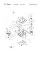
- FIG. 2is an enlarged, cross-sectional view of a portion of FIG. 1 which includes the spindle motor and a plurality of disks;
- FIG. 3is an enlarged, cross-sectional view of a portion of FIG. 2;
- FIG. 4is an enlarged, top plan view of a wire guide body
- FIG. 5is an exploded view of a portion of the spindle motor of FIG. 2 .
- a disk drive 10 embodying one preferred embodiment of the present inventionincludes a head disk assembly 12 and a printed circuit board assembly 14 .
- the printed circuit board assembly 14is suitably secured to an exterior of the head disk assembly 12 and controls operation of various components thereof.
- the head disk assembly 12includes an enclosure 16 , a magnetic disk 18 , a magnetic transducer 20 , a rotary actuator arrangement 22 and a spindle motor generally indicated at 24 .
- the magnetic disk 18 , the magnetic transducer 20 , the rotary actuator arrangement 22 and the spindle motor 24are contained within the enclosure 16 .
- the enclosure 16comprises a base 26 and a cover 28 .
- the enclosure 16is sealed to provide a relatively contaminant-free interior for remaining components of the head disk assembly 12 .
- a tape seal 30is used to seal the enclosure 16 .
- the magnetic disk 18 and the magnetic transducer 20are positioned within an interior of the enclosure 16 .
- the magnetic disk 18includes a recording surface 32 .
- the magnetic disk 18has a substrate formed from aluminum or aluminum alloy, with the recording surface including magnetic material deposited on the aluminum substrate.
- the particular embodiment shown in FIG. 1includes a stack of two disks 18 providing four recording surfaces 32 , and includes four magnetic transducers 20 .
- the number of disks 18may be less than or greater than 2.
- the number of transducers 20corresponds with the number of disks 18 .
- the rotary actuator arrangement 22provides for positioning of the magnetic transducers 20 over a selected area of the recording surfaces 32 of the magnetic disks 18 .
- the rotary actuator arrangement 22includes a permanent-magnet arrangement generally indicated at 34 , a pivot bearing cartridge 36 and a head stack assembly 38 .
- the pivot bearing cartridge 36includes a stationary shaft secured to the enclosure 16 to define an axis of rotation for the rotary actuator arrangement 22 .
- the head stack assembly 38includes a flex circuit assembly 40 , a coil 42 and actuator arms 44 . Each one of the magnetic transducers 20 is coupled to a respective one of the arms 44 via respective load beams (“suspensions”).
- circuitrycauses current to conduct through the coil 42 , and because the coil 42 lies in the magnetic field provided by the permanent magnet arrangement 34 , a torque is applied to the head stack assembly 38 .
- the amount and direction of that torqueis subject to control by a servo system that controls the rotary position of the magnetic transducer 20 relative to the respective recording surface 32 of the magnetic disk 18 .
- the disk 18is mounted to the spindle motor 24 and causes each disk 18 to spin, preferably at a constant angular velocity.
- the spindle motor 24is shown in more detail in FIG. 2 .
- the spindle motor 24includes a spindle motor base 50 , a stationary shaft 52 , an upper bearing 54 , a lower bearing 56 , a stator 58 , a magnet 60 , a hub 62 , a connector ring 64 and a wire guide body 66 . Details of the various components are provided below.
- the shaft 52is secured to the spindle motor base 50 .
- the upper bearing 54 and the lower bearing 56are spaced-apart along the shaft 52 and rotatably secure the hub 62 about the shaft 52 .
- the connector ring 64couples the hub 62 to the lower bearing 56 .
- the magnet 60is connected to the hub 62 .
- the wire guide body 66is secured between the shaft 52 and the lower bearing 56 . It will be recognized that the spindle motor 24 depicted in FIG. 2 is a split bearing design.
- the spindle motor base 50is made of a rigid material, such as aluminum, and is suitably sized to be received by the base 26 (FIG. 1) of the enclosure 16 (FIG. 1 ).
- the shaft 52is made of a rigid material, such as aluminum or steel, and is suitably sized to be received by the spindle motor base 50 .
- the shaft 52suitably has a uniform diameter and is configured to extend in a perpendicular fashion from a central portion 70 of the spindle motor base 50 so as to define a longitudinal axis Y.
- the shaft 52includes a bore 72 suitably sized to receive a screw for securing the shaft 52 to the enclosure 16 (FIG. 1 ).
- the upper bearing 54 and the lower bearing 56each include an inner race 74 , an outer race 76 and bearing balls 78 .
- the inner race 74is associated with the outer race 76 so as to contain the balls 78 .
- the inner race 74 , the outer race 76 and the balls 78are suitably made from a metal such as stainless steel or a non-metallic material such as ceramic material. While the upper bearing 54 and the lower bearing 56 are highly similar in construction, the lower bearing 56 may be slightly smaller than the upper bearing 54 . Further, the inner race 74 of the lower bearing 56 may have a larger diameter than the inner race 74 of the upper bearing 54 .
- the upper and lower bearingsare the same size; in such a preferred embodiment, the area of the shaft adjacent to the inner race 74 of the upper bearing 54 would define a stepped protrusion such that the upper bearing's inner race would abut the stepped protrusion. With such a configuration, the upper and lower bearings would line up radially. In other words, relative to the shaft, the respective inner diameters of the inner races will be the same as well as the respective outer diameters of the outer races.
- the stator 58preferably has a ring configuration, and includes a stator core 80 and wires generally shown at 82 .
- the wires 82are wound about the stator core 80 .
- Each of the individual wiresfor example the wire 82 a and the wire 82 b , includes a leading portion 84 that extends away from (downwardly relative to the orientation of FIG. 2) the stator core 80 , terminating in a leading end 86 .
- the leading end 86 of each of the wires 82 a and 82 bis fed through a suitable opening (not shown) in the spindle motor base 50 and is electrically connected to a current supply, such as that provided by the printed circuit board assembly 14 (shown generally in FIG. 2 ).
- a current supplysuch as that provided by the printed circuit board assembly 14 (shown generally in FIG. 2 ).
- the wires 82 a , 82 bmay extend directly from a bottom of the core 80 , or may instead be directed through a passage in the core 80 from a top to the bottom.
- the wiresinclude at least three wires wound about the stator core 80 , each of the three wires defining a separate coil able to selectively receive an independent current supply. With this configuration, energizing one set of coils forms an electromagnet at that particular coil.
- the magnet 60is suitably in the shape of a ring, and is defined by a first half 88 and a second half 90 . With this configuration, each half defines suitably four magnetic poles.
- the hub 62is generally cylindrical in shape, definable by an upper portion 92 and a lower portion 94 .
- the upper portion 92is sized for attachment to the upper bearing 54 and to receive a clamping device (not shown) via bores 96 . More particularly, the clamping device is mounted to the hub 62 via screws extending into the bores 96 to mount the stack of disks 18 to the hub 62 .
- the lower portion 94is integral with the upper portion 92 and terminates in a flange 98 .
- the flange 98extends in a radial fashion and is suitably sized to receive the disks 18 .
- the hub 62is formed from a hardened material such as aluminum or steel.
- the connector ring 64is suitably formed from a hardened material such as steel and is sized to couple the lower portion 94 of the hub 62 with the outer race 76 of the lower bearing 56 . Further, the connector ring 64 provides a contaminant seal between the lower bearing 56 and the spindle motor base 50 .
- the wire guide body 66is best described with reference to FIG. 3, which, for ease of illustration, omits the spindle motor base 50 (FIG. 2 ).
- the wire guide body 66is ring-shaped and suitably forms a first channel 100 and a second channel 102 .
- the wire guide body 66is suitably made of a hardened material such as steel and is sized to be secured between the shaft 52 and the inner race 74 of the lower bearing 56 .
- the wire guide body 66preferably has a longitudinal height contiguous with that of the lower bearing 56 . In this regard, the wire guide body 66 may assume a wide variety of dimensions, suitably corresponding to a height and inner diameter of the lower bearing 56 .
- the first channel 100is suitably sized to receive a plurality of wires including the first wire 82 a whereas the second channel 102 is sized to receive a plurality of wires including the second wire 82 b .
- the wire guide body 66includes an inner wall 104 , an outer wall 106 , a top 108 and a bottom 110 .
- the inner wall 104is a generally cylindrically shaped surface extending between the top 108 and the bottom 110 .
- the outer wall 106is a generally cylindrically shaped surface extending between the top 108 and the bottom 110 .
- the first channel 100is formed adjacent to the inner wall 104 such that the channel is radially open, as best shown in FIG. 4 . Further, the first channel 100 is axially open at the top 108 and the bottom 110 . Upon final assembly, the first channel 100 opens into the shaft 52 as depicted in FIG. 3 .
- the second channel 100is formed adjacent to the outer wall 106 such that the second channel 102 is radially open, as shown in FIG. 3 . Additionally, the second channel 102 is axially open at the top 108 and the bottom 110 . Upon final assembly (FIG. 3 ), the second channel 102 opens into the inner race 74 of the lower bearing 56 .
- the wire guide body 66has been described as including the first channel 100 and the second channel 102 . However, in a preferred embodiment as previously described, the wire guide body 66 includes only a single channel. In an alternative embodiment, the wire guide body 66 may include more than two channels. The channels may be formed adjacent to only one of the cylindrically shaped inner wall 104 or the outer wall 106 . Further, the first channel 100 and/or the second channel 102 may be sized to receive more than one of the wires 82 a , 82 b . Finally, while the first channel 100 and the second channel 102 have been depicted as preferably being radially open along an entire longitudinal height of the wire guide body 66 , only a portion of the channel 100 or 102 need be radially open.
- the wire guide body 66facilitates a number of acceptable assembly procedures for the spindle motor 24 , one of which is substantially as follows.
- the stator 58is secured to the shaft 52 , such as by a press fitting operation.
- the leading portions 84 of the wires 82 a , 82 bare extended away from the stator core 80 .
- the wire guide body 66is then generally axially aligned with the shaft 52 below the stator 58 . Where it is desirable for one or more of the wires to pass through the first channel 100 (i.e., proximal the shaft 52 ), for example the wire 82 a , the leading portion 84 is radially inserted into the first channel 100 .
- the wire guide body 66is then secured to the shaft 52 below the stator 58 , such as by a press fitting operation. Where it is desirable for one or more of the wires to pass through the second channel 102 , for example the wire 82 b , the leading portion 84 of the wire 82 b is placed into the second channel 102 . More particularly, the leading portion 84 is radially inserted into the second channel 102 . Once inserted, the leading end 86 of the wire 82 b extends from the bottom 110 of the wire guide body 66 , as depicted in FIG. 3 .
- the lower bearing 56is then secured about the wire guide body 66 , such as with an adhesive.
- the inner race 74 of the lower bearing 56is secured to the outer wall 106 of the wire guide body 66 .
- the shaft 52is then secured to the spindle motor base 50 , such as by a press fitting operation. As shown in FIG. 2, the shaft 52 extends from the spindle motor base 50 in a generally perpendicular fashion to define the longitudinal axis Y.
- the upper bearing 54is secured to the shaft 52 .
- the inner race 74 of the upper bearing 54is secured to the shaft 52 , axially spaced from the stator 58 .
- the connector ring 64is sealed to the outer race 76 of the lower bearing 56 .
- the hub 62 and the magnet 60are assembled and then positioned about the shaft 52 along a direction of the longitudinal axis Y.
- the upper portion 92is secured to the outer race 76 of the upper bearing 54 whereas the lower portion 94 is secured to the connector ring 64 otherwise coupled to the outer race 76 of the lower bearing 56 .
- the stator 58is substantially coextensive with the magnet 60 .
- the hub 62can rotate about the shaft 52 via the upper and lower bearings 54 , 56 .
- the leading end 86 of the wires 82 a , 82 bis passed through the spindle motor base 50 and connected to the printed circuit board assembly 14 ..
- the wire guide body 66may be secured to the shaft 52 before the wire 82 a is fed through the channel 100 .
- the lower bearing 56may be adhered to the wire guide body 66 prior to securing the wire guide body 66 to the shaft 52 .
- FIG. 2depicts a stack of disks 18 , with a spacer 120 between any two given disks 18 .
- the disks 18along with a respective spacer 120 , are secured to the flange 98 by a clamping device (not shown) attached to the upper portion 92 of the hub 62 .
- the spindle motor 24operates as follows. Cyclical energization of the wires 82 a , 82 b of the stator 58 imparts a rotational torque onto the magnet 60 and thus the hub 62 . The disks 18 , otherwise attached to the hub 62 , likewise rotate. Significantly, because the shaft 52 does not include a slot for the stator wires, the shaft 52 is stiffer. As a result, the shaft 52 will vibrate less during the operation of the disk drive.
- the disk drive 10(FIG. 1) having the spindle motor 24 in accordance with the present invention provides a distinct improvement over previous designs in terms of ease-of-assembly and performance. More particularly, utilization of a wire guide body incorporating at least one channel for directing stator wire(s) around the lower bearing eliminates the need to gouge a slot into the shaft. Further, because the channel is radially open, the stator wires are easily inserted into the channel, and the risk of wire damage during assembly decreases.
Landscapes
- Engineering & Computer Science (AREA)
- Power Engineering (AREA)
- Rotational Drive Of Disk (AREA)
Abstract
Description
Claims (14)
Priority Applications (1)
| Application Number | Priority Date | Filing Date | Title |
|---|---|---|---|
| US09/225,161US6215616B1 (en) | 1999-01-04 | 1999-01-04 | Disk drive spindle motor with wire guide insert |
Applications Claiming Priority (1)
| Application Number | Priority Date | Filing Date | Title |
|---|---|---|---|
| US09/225,161US6215616B1 (en) | 1999-01-04 | 1999-01-04 | Disk drive spindle motor with wire guide insert |
Publications (1)
| Publication Number | Publication Date |
|---|---|
| US6215616B1true US6215616B1 (en) | 2001-04-10 |
Family
ID=22843786
Family Applications (1)
| Application Number | Title | Priority Date | Filing Date |
|---|---|---|---|
| US09/225,161Expired - Fee RelatedUS6215616B1 (en) | 1999-01-04 | 1999-01-04 | Disk drive spindle motor with wire guide insert |
Country Status (1)
| Country | Link |
|---|---|
| US (1) | US6215616B1 (en) |
Cited By (55)
| Publication number | Priority date | Publication date | Assignee | Title |
|---|---|---|---|---|
| US6498407B1 (en)* | 1998-05-01 | 2002-12-24 | Xyratex Technology Limited | Low speed moving magnet motor having a high inertia rotor |
| US20050210490A1 (en)* | 2004-03-17 | 2005-09-22 | Nidec Corporation | Disk Drive Motor and Disk Drive Device Having the Same |
| US20100133938A1 (en)* | 2008-12-02 | 2010-06-03 | Alex Horng | Rotor |
| US20110169381A1 (en)* | 2010-03-15 | 2011-07-14 | Motor Excellence Llc | Transverse and/or commutated flux systems for electric bicycles |
| US8053944B2 (en) | 2010-03-15 | 2011-11-08 | Motor Excellence, Llc | Transverse and/or commutated flux systems configured to provide reduced flux leakage, hysteresis loss reduction, and phase matching |
| US8193679B2 (en) | 2008-11-03 | 2012-06-05 | Motor Excellence Llc | Polyphase transverse and/or commutated flux systems |
| US8222786B2 (en) | 2010-03-15 | 2012-07-17 | Motor Excellence Llc | Transverse and/or commutated flux systems having phase offset |
| US8405275B2 (en) | 2010-11-17 | 2013-03-26 | Electric Torque Machines, Inc. | Transverse and/or commutated flux systems having segmented stator laminations |
| US8836196B2 (en) | 2010-11-17 | 2014-09-16 | Electric Torque Machines, Inc. | Transverse and/or commutated flux systems having segmented stator laminations |
| US8908319B1 (en) | 2013-04-18 | 2014-12-09 | Western Digital Technologies, Inc. | Disk drive with slow acting desiccant |
| US8908325B1 (en) | 2013-03-08 | 2014-12-09 | Western Digital Technologies, Inc. | Threaded disk clamping element with step on disk contact surface |
| US8941952B1 (en) | 2014-06-10 | 2015-01-27 | Western Digital Technologies, Inc. | Disk drive head stack assembly having a flexible printed circuit with bond pads having reduced capacitance |
| US8952590B2 (en) | 2010-11-17 | 2015-02-10 | Electric Torque Machines Inc | Transverse and/or commutated flux systems having laminated and powdered metal portions |
| US8970984B1 (en) | 2014-04-29 | 2015-03-03 | Western Digital Technologies, Inc. | Grooved cylindrical seal with increased radial clearance for reduced cost disk drive spindle |
| US8995094B1 (en) | 2014-02-28 | 2015-03-31 | Western Digital Technologies, Inc. | Disk drive head suspension with a dual dimple and a flexure tongue with a piezoelectric microactuator |
| US9007716B1 (en) | 2012-09-24 | 2015-04-14 | Western Digital Technologies, Inc. | Spindle motor magnet diameter increase above head plane |
| US9019657B1 (en) | 2013-03-13 | 2015-04-28 | Western Digital Technologies, Inc. | Coined VCM tab to limit cover deflection under pinch load |
| US9025284B1 (en) | 2014-02-26 | 2015-05-05 | Western Digital Technologies, Inc. | Disk drive with self sealing screw attachment of actuator pivot |
| US9036295B1 (en) | 2011-12-20 | 2015-05-19 | Western Digital Technologies, Inc. | Information storage device with a damping insert sheet between a housing bay and a disk drive |
| US9058851B1 (en) | 2014-07-02 | 2015-06-16 | Western Digital Technologies, Inc. | Information-storage device including an oxygen absorbing device |
| US9099153B2 (en) | 2013-04-03 | 2015-08-04 | Western Digital Technologies, Inc. | Storage device with a cover supporting portion |
| US9099131B1 (en) | 2010-03-17 | 2015-08-04 | Western Digital Technologies, Inc. | Suspension assembly having a microactuator electrically connected to a gold coating on a stainless steel surface |
| US9116066B1 (en) | 2012-04-27 | 2015-08-25 | Western Digital Technologies, Inc. | Devices and methods for system-level disk drive vibration and shock testing |
| US9123387B1 (en) | 2014-08-21 | 2015-09-01 | WD Media, LLC | Magnetic recording drives with active photocatalytic filtration |
| US9129639B1 (en) | 2012-11-08 | 2015-09-08 | Western Digital Technologies, Inc. | Method of imbalance correction using a grooved disk clamp |
| US9147436B2 (en) | 2012-04-25 | 2015-09-29 | Western Digital Technologies, Inc. | Slim form factor disk drive comprising disk drive enclosure having an insular raised region |
| US9153262B1 (en) | 2015-03-26 | 2015-10-06 | Western Digital Technologies, Inc. | Disk drive actuator having a radially stepped pivot bore |
| US9159205B1 (en) | 2013-12-18 | 2015-10-13 | Western Digital Technologies, Inc. | Tamper-evident seals having adhesive-free areas to minimize rework time |
| US9165580B2 (en) | 2013-12-10 | 2015-10-20 | Western Digital Technologies, Inc. | Disk drive head suspension tail with stiffened edge alignment features |
| US9171583B1 (en) | 2015-03-23 | 2015-10-27 | Western Digital Technologies, Inc. | Disk drive having a top cover channel vented to a central cavity via a peripheral clearance gap |
| US9171560B1 (en) | 2014-09-26 | 2015-10-27 | Western Digital Technologies, Inc. | Sloping transition on a ramp of a hard disk drive |
| US9183889B1 (en) | 2015-03-23 | 2015-11-10 | Western Digital Technologies, Inc. | Disk drive having a top cover channel vented to a central cavity via a hole through a bottom land |
| US9190114B1 (en) | 2015-02-09 | 2015-11-17 | Western Digital Technologies, Inc. | Disk drive filter including fluorinated and non-fluorinated nanopourous organic framework materials |
| US9196275B1 (en) | 2014-03-12 | 2015-11-24 | Western Digital Technologies, Inc. | Magnetic head separator fin material to prevent particulate contamination on slider |
| US9196292B1 (en) | 2015-02-05 | 2015-11-24 | Western Digital Technologies, Inc. | Rotary spindle having a disk clamp bottom land facing and in contact with a shaft top land |
| US9196301B1 (en) | 2011-10-14 | 2015-11-24 | Western Digital Technologies, Inc. | Suspension clamp for clamping a disk drive suspension to an actuator arm |
| US9208825B1 (en) | 2013-08-07 | 2015-12-08 | Western Digital Technologies, Inc. | Disk drive having a conformal peripheral foil seal having an opening covered by a central metal cap |
| US9214174B1 (en) | 2010-10-29 | 2015-12-15 | Western Digital Technologies, Inc. | Method of manufacturing a disk drive head gimbal assembly having a flexure tail with folded bond pads |
| US9263070B1 (en) | 2014-11-05 | 2016-02-16 | Western Digital Technologies, Inc. | Actuator pivot assembly including a bonding adhesive barrier configured to reduce contamination |
| US9299384B1 (en) | 2012-08-02 | 2016-03-29 | Western Digital Technologies, Inc. | Ultra-thin HDD embedded disk clamp design |
| US9324344B1 (en) | 2013-12-10 | 2016-04-26 | Western Digital Technologies, Inc. | Disk drive head suspension tail with ground pad outside of bonding region |
| US9330695B1 (en) | 2013-12-10 | 2016-05-03 | Western Digital Technologies, Inc. | Disk drive head suspension tail with a noble metal layer disposed on a plurality of structural backing islands |
| US9379311B1 (en) | 2005-12-09 | 2016-06-28 | Western Digital Technologies, Inc. | Apparatus for manufacturing piezoelectric actuators |
| US9390736B1 (en) | 2014-03-13 | 2016-07-12 | Western Digital Technologies, Inc. | Magnetic head separator connected to a ramp |
| US9406333B1 (en) | 2015-11-10 | 2016-08-02 | Western Digital Technologies, Inc. | Disk drive having a stationary plate between disks with grooves adjacent fastener holes |
| US9472242B1 (en) | 2015-06-05 | 2016-10-18 | Western Digital Technologies, Inc. | Hard disk drive enclosure base with feed through flexure design and accompanying flexure |
| US9508393B1 (en) | 2015-06-25 | 2016-11-29 | Western Digital Technologies, Inc. | Hard disk drive enclosure base with a helium sealed gasket |
| US9514773B2 (en) | 2008-08-20 | 2016-12-06 | Western Digital Technologies, Inc. | Head stack assembly with a flexible printed circuit having a mouth centered between arms |
| US9524738B1 (en) | 2015-06-25 | 2016-12-20 | Western Digital Technologies, Inc. | Disk drive head gimbal assembly having a flexure tail with a dielectric layer that has regions of lesser thickness |
| US9564156B1 (en) | 2016-01-27 | 2017-02-07 | Western Digital Technologies, Inc. | Head gimbal assembly having a flexure tail with cover layer standoff islands |
| US9633680B2 (en) | 2010-10-29 | 2017-04-25 | Western Digital Technologies, Inc. | Head suspension having a flexure tail with a covered conductive layer and structural layer bond pads |
| US9662753B1 (en) | 2014-03-10 | 2017-05-30 | Western Digital Technologies, Inc. | Disk drive spindle with fluid journal bearing having increased radial clearance in axial end regions |
| US9908167B1 (en) | 2015-03-02 | 2018-03-06 | Western Digital Technologies, Inc. | Disk drive tolerance ring with edge rounding from opposite major faces |
| CN110661363A (en)* | 2018-06-28 | 2020-01-07 | 罗伯特·博世有限公司 | Hub motor assembly and bearing unit for vehicle |
| US20240033902A1 (en)* | 2015-10-06 | 2024-02-01 | Flx Solutions Inc. | Snake-Like Robot |
Citations (8)
| Publication number | Priority date | Publication date | Assignee | Title |
|---|---|---|---|---|
| US5138209A (en)* | 1990-03-01 | 1992-08-11 | Nippon Densan Corporation | Spindle motor |
| US5173814A (en) | 1981-09-07 | 1992-12-22 | Papst-Motoren Gmbh & Co. Kg | Disk storage drive having internal electrical connection passages and contamination seals at ends of the motor |
| US5459361A (en)* | 1992-07-14 | 1995-10-17 | Nippon Densan Corporation | Spindle motor |
| US5493159A (en)* | 1994-07-19 | 1996-02-20 | Synektron Corporation | Flex circuit for electric motor |
| US5528092A (en)* | 1992-06-23 | 1996-06-18 | Nippon Corporation | Spindle motor |
| US5598047A (en)* | 1992-06-09 | 1997-01-28 | Matsushita Electric Industrial Co., Ltd, | Electric motor for driving magnetic disk |
| US5831355A (en)* | 1995-10-06 | 1998-11-03 | Nidec Corporation | Spindle motor |
| US5945751A (en)* | 1991-06-28 | 1999-08-31 | Papst Licensing Gmbh | Disk storage device having a spindle driving motor |
- 1999
- 1999-01-04USUS09/225,161patent/US6215616B1/ennot_activeExpired - Fee Related
Patent Citations (8)
| Publication number | Priority date | Publication date | Assignee | Title |
|---|---|---|---|---|
| US5173814A (en) | 1981-09-07 | 1992-12-22 | Papst-Motoren Gmbh & Co. Kg | Disk storage drive having internal electrical connection passages and contamination seals at ends of the motor |
| US5138209A (en)* | 1990-03-01 | 1992-08-11 | Nippon Densan Corporation | Spindle motor |
| US5945751A (en)* | 1991-06-28 | 1999-08-31 | Papst Licensing Gmbh | Disk storage device having a spindle driving motor |
| US5598047A (en)* | 1992-06-09 | 1997-01-28 | Matsushita Electric Industrial Co., Ltd, | Electric motor for driving magnetic disk |
| US5528092A (en)* | 1992-06-23 | 1996-06-18 | Nippon Corporation | Spindle motor |
| US5459361A (en)* | 1992-07-14 | 1995-10-17 | Nippon Densan Corporation | Spindle motor |
| US5493159A (en)* | 1994-07-19 | 1996-02-20 | Synektron Corporation | Flex circuit for electric motor |
| US5831355A (en)* | 1995-10-06 | 1998-11-03 | Nidec Corporation | Spindle motor |
Cited By (65)
| Publication number | Priority date | Publication date | Assignee | Title |
|---|---|---|---|---|
| US6498407B1 (en)* | 1998-05-01 | 2002-12-24 | Xyratex Technology Limited | Low speed moving magnet motor having a high inertia rotor |
| US20050210490A1 (en)* | 2004-03-17 | 2005-09-22 | Nidec Corporation | Disk Drive Motor and Disk Drive Device Having the Same |
| US9379311B1 (en) | 2005-12-09 | 2016-06-28 | Western Digital Technologies, Inc. | Apparatus for manufacturing piezoelectric actuators |
| US9514773B2 (en) | 2008-08-20 | 2016-12-06 | Western Digital Technologies, Inc. | Head stack assembly with a flexible printed circuit having a mouth centered between arms |
| US8242658B2 (en) | 2008-11-03 | 2012-08-14 | Electric Torque Machines Inc. | Transverse and/or commutated flux system rotor concepts |
| US8193679B2 (en) | 2008-11-03 | 2012-06-05 | Motor Excellence Llc | Polyphase transverse and/or commutated flux systems |
| US20100133938A1 (en)* | 2008-12-02 | 2010-06-03 | Alex Horng | Rotor |
| US7884513B2 (en)* | 2008-12-02 | 2011-02-08 | Sunonwealth Electric Machine Industry Co., Ltd. | Rotor |
| US20110169381A1 (en)* | 2010-03-15 | 2011-07-14 | Motor Excellence Llc | Transverse and/or commutated flux systems for electric bicycles |
| US8222786B2 (en) | 2010-03-15 | 2012-07-17 | Motor Excellence Llc | Transverse and/or commutated flux systems having phase offset |
| US8395291B2 (en)* | 2010-03-15 | 2013-03-12 | Electric Torque Machines, Inc. | Transverse and/or commutated flux systems for electric bicycles |
| US8053944B2 (en) | 2010-03-15 | 2011-11-08 | Motor Excellence, Llc | Transverse and/or commutated flux systems configured to provide reduced flux leakage, hysteresis loss reduction, and phase matching |
| US8760023B2 (en)* | 2010-03-15 | 2014-06-24 | Electric Torque Machines, Inc. | Transverse and/or commutated flux systems having phase offset |
| US9099131B1 (en) | 2010-03-17 | 2015-08-04 | Western Digital Technologies, Inc. | Suspension assembly having a microactuator electrically connected to a gold coating on a stainless steel surface |
| US9472218B2 (en) | 2010-03-17 | 2016-10-18 | Western Digital Technologies, Inc. | Suspension assembly having a microactuator electrically connected to a gold coating on a stainless steel surface |
| US9633680B2 (en) | 2010-10-29 | 2017-04-25 | Western Digital Technologies, Inc. | Head suspension having a flexure tail with a covered conductive layer and structural layer bond pads |
| US9214174B1 (en) | 2010-10-29 | 2015-12-15 | Western Digital Technologies, Inc. | Method of manufacturing a disk drive head gimbal assembly having a flexure tail with folded bond pads |
| US9953667B2 (en) | 2010-10-29 | 2018-04-24 | Western Digital Technologies, Inc. | Disk drive system |
| US8836196B2 (en) | 2010-11-17 | 2014-09-16 | Electric Torque Machines, Inc. | Transverse and/or commutated flux systems having segmented stator laminations |
| US8405275B2 (en) | 2010-11-17 | 2013-03-26 | Electric Torque Machines, Inc. | Transverse and/or commutated flux systems having segmented stator laminations |
| US8952590B2 (en) | 2010-11-17 | 2015-02-10 | Electric Torque Machines Inc | Transverse and/or commutated flux systems having laminated and powdered metal portions |
| US8854171B2 (en) | 2010-11-17 | 2014-10-07 | Electric Torque Machines Inc. | Transverse and/or commutated flux system coil concepts |
| US9196301B1 (en) | 2011-10-14 | 2015-11-24 | Western Digital Technologies, Inc. | Suspension clamp for clamping a disk drive suspension to an actuator arm |
| US9036295B1 (en) | 2011-12-20 | 2015-05-19 | Western Digital Technologies, Inc. | Information storage device with a damping insert sheet between a housing bay and a disk drive |
| US9147436B2 (en) | 2012-04-25 | 2015-09-29 | Western Digital Technologies, Inc. | Slim form factor disk drive comprising disk drive enclosure having an insular raised region |
| US9116066B1 (en) | 2012-04-27 | 2015-08-25 | Western Digital Technologies, Inc. | Devices and methods for system-level disk drive vibration and shock testing |
| US9299384B1 (en) | 2012-08-02 | 2016-03-29 | Western Digital Technologies, Inc. | Ultra-thin HDD embedded disk clamp design |
| US9007716B1 (en) | 2012-09-24 | 2015-04-14 | Western Digital Technologies, Inc. | Spindle motor magnet diameter increase above head plane |
| US9129639B1 (en) | 2012-11-08 | 2015-09-08 | Western Digital Technologies, Inc. | Method of imbalance correction using a grooved disk clamp |
| US8908325B1 (en) | 2013-03-08 | 2014-12-09 | Western Digital Technologies, Inc. | Threaded disk clamping element with step on disk contact surface |
| US9019657B1 (en) | 2013-03-13 | 2015-04-28 | Western Digital Technologies, Inc. | Coined VCM tab to limit cover deflection under pinch load |
| US9099153B2 (en) | 2013-04-03 | 2015-08-04 | Western Digital Technologies, Inc. | Storage device with a cover supporting portion |
| US9305599B2 (en) | 2013-04-03 | 2016-04-05 | Western Digital Technologies, Inc. | Storage device with a cover supporting portion |
| US8908319B1 (en) | 2013-04-18 | 2014-12-09 | Western Digital Technologies, Inc. | Disk drive with slow acting desiccant |
| US9208825B1 (en) | 2013-08-07 | 2015-12-08 | Western Digital Technologies, Inc. | Disk drive having a conformal peripheral foil seal having an opening covered by a central metal cap |
| US9330695B1 (en) | 2013-12-10 | 2016-05-03 | Western Digital Technologies, Inc. | Disk drive head suspension tail with a noble metal layer disposed on a plurality of structural backing islands |
| US9165580B2 (en) | 2013-12-10 | 2015-10-20 | Western Digital Technologies, Inc. | Disk drive head suspension tail with stiffened edge alignment features |
| US9881640B2 (en) | 2013-12-10 | 2018-01-30 | Western Digital Technologies, Inc. | Disk drive head suspension tail with a noble metal layer disposed on a plurality of structural backing islands |
| US9530439B2 (en) | 2013-12-10 | 2016-12-27 | Western Digital Technologies, Inc. | Disk drive head suspension tail with stiffened edge alignment features |
| US9324344B1 (en) | 2013-12-10 | 2016-04-26 | Western Digital Technologies, Inc. | Disk drive head suspension tail with ground pad outside of bonding region |
| US9159205B1 (en) | 2013-12-18 | 2015-10-13 | Western Digital Technologies, Inc. | Tamper-evident seals having adhesive-free areas to minimize rework time |
| US9025284B1 (en) | 2014-02-26 | 2015-05-05 | Western Digital Technologies, Inc. | Disk drive with self sealing screw attachment of actuator pivot |
| US8995094B1 (en) | 2014-02-28 | 2015-03-31 | Western Digital Technologies, Inc. | Disk drive head suspension with a dual dimple and a flexure tongue with a piezoelectric microactuator |
| US9662753B1 (en) | 2014-03-10 | 2017-05-30 | Western Digital Technologies, Inc. | Disk drive spindle with fluid journal bearing having increased radial clearance in axial end regions |
| US9196275B1 (en) | 2014-03-12 | 2015-11-24 | Western Digital Technologies, Inc. | Magnetic head separator fin material to prevent particulate contamination on slider |
| US9390736B1 (en) | 2014-03-13 | 2016-07-12 | Western Digital Technologies, Inc. | Magnetic head separator connected to a ramp |
| US8970984B1 (en) | 2014-04-29 | 2015-03-03 | Western Digital Technologies, Inc. | Grooved cylindrical seal with increased radial clearance for reduced cost disk drive spindle |
| US8941952B1 (en) | 2014-06-10 | 2015-01-27 | Western Digital Technologies, Inc. | Disk drive head stack assembly having a flexible printed circuit with bond pads having reduced capacitance |
| US9058851B1 (en) | 2014-07-02 | 2015-06-16 | Western Digital Technologies, Inc. | Information-storage device including an oxygen absorbing device |
| US9123387B1 (en) | 2014-08-21 | 2015-09-01 | WD Media, LLC | Magnetic recording drives with active photocatalytic filtration |
| US9171560B1 (en) | 2014-09-26 | 2015-10-27 | Western Digital Technologies, Inc. | Sloping transition on a ramp of a hard disk drive |
| US9263070B1 (en) | 2014-11-05 | 2016-02-16 | Western Digital Technologies, Inc. | Actuator pivot assembly including a bonding adhesive barrier configured to reduce contamination |
| US9196292B1 (en) | 2015-02-05 | 2015-11-24 | Western Digital Technologies, Inc. | Rotary spindle having a disk clamp bottom land facing and in contact with a shaft top land |
| US9190114B1 (en) | 2015-02-09 | 2015-11-17 | Western Digital Technologies, Inc. | Disk drive filter including fluorinated and non-fluorinated nanopourous organic framework materials |
| US9908167B1 (en) | 2015-03-02 | 2018-03-06 | Western Digital Technologies, Inc. | Disk drive tolerance ring with edge rounding from opposite major faces |
| US9183889B1 (en) | 2015-03-23 | 2015-11-10 | Western Digital Technologies, Inc. | Disk drive having a top cover channel vented to a central cavity via a hole through a bottom land |
| US9171583B1 (en) | 2015-03-23 | 2015-10-27 | Western Digital Technologies, Inc. | Disk drive having a top cover channel vented to a central cavity via a peripheral clearance gap |
| US9153262B1 (en) | 2015-03-26 | 2015-10-06 | Western Digital Technologies, Inc. | Disk drive actuator having a radially stepped pivot bore |
| US9472242B1 (en) | 2015-06-05 | 2016-10-18 | Western Digital Technologies, Inc. | Hard disk drive enclosure base with feed through flexure design and accompanying flexure |
| US9524738B1 (en) | 2015-06-25 | 2016-12-20 | Western Digital Technologies, Inc. | Disk drive head gimbal assembly having a flexure tail with a dielectric layer that has regions of lesser thickness |
| US9508393B1 (en) | 2015-06-25 | 2016-11-29 | Western Digital Technologies, Inc. | Hard disk drive enclosure base with a helium sealed gasket |
| US20240033902A1 (en)* | 2015-10-06 | 2024-02-01 | Flx Solutions Inc. | Snake-Like Robot |
| US9406333B1 (en) | 2015-11-10 | 2016-08-02 | Western Digital Technologies, Inc. | Disk drive having a stationary plate between disks with grooves adjacent fastener holes |
| US9564156B1 (en) | 2016-01-27 | 2017-02-07 | Western Digital Technologies, Inc. | Head gimbal assembly having a flexure tail with cover layer standoff islands |
| CN110661363A (en)* | 2018-06-28 | 2020-01-07 | 罗伯特·博世有限公司 | Hub motor assembly and bearing unit for vehicle |
Similar Documents
| Publication | Publication Date | Title |
|---|---|---|
| US6215616B1 (en) | Disk drive spindle motor with wire guide insert | |
| US6185067B1 (en) | Disk drive with reduced thermal expansion induced disk slip | |
| US6316853B1 (en) | Spindle motor assembly for disc drives | |
| US6888697B1 (en) | Disk drive having a disk plate body attached to a fixed spindle shaft of a spindle motor | |
| US5157295A (en) | Under-the-hub disk drive spin motor | |
| US7436625B1 (en) | Disk drive spindle motor having a cavity defined by one of an upper surface of a stator support structure and a lower surface of a stator tooth | |
| EP0535018B1 (en) | Low noise spin motor for use in disk drive | |
| EP0558355B1 (en) | Compact, high-speed, rotary actuator | |
| US5528436A (en) | Low profile motor powered disk assembly for a recording/reproducing device | |
| US20010048574A1 (en) | Resonance four-piece suspension | |
| US6654208B2 (en) | Reduced inertia actuator pivot assembly | |
| US7199971B1 (en) | Balancing a rotatable body in multiple planes using invertible balancing plugs | |
| US20040090701A1 (en) | Slim spindle motor and micro-drive apparatus comprising the same | |
| US5400197A (en) | Disc drive spindle motor | |
| US6204996B1 (en) | Low profile spindle motor | |
| US6556375B2 (en) | Hard disk drive device | |
| US5583721A (en) | Connecting device of a flexible printed circuit in a hard disk drive | |
| US6744606B2 (en) | Dual plane actuator | |
| US5726829A (en) | Axial spindle motor for hard disk drive assembly | |
| US20050225893A1 (en) | Recording medium drive capable of preventing flexure of base and cover | |
| US6762908B2 (en) | Air razor and disk limiter for a hard disk drive | |
| US5602701A (en) | Head actuator for magnetic disk drive unit | |
| US6226156B1 (en) | Magnetic read/write head actuator assembly having an actuator motor with dual windings | |
| JPH09312058A (en) | Spindle motor for flexible disk drive and its balance adjusting method | |
| CN1115072A (en) | Drum motor unit |
Legal Events
| Date | Code | Title | Description |
|---|---|---|---|
| AS | Assignment | Owner name:WESTERN DIGITAL CORPORATION, CALIFORNIA Free format text:ASSIGNMENT OF ASSIGNORS INTEREST;ASSIGNORS:SASSINE, JOSEPH H.;PHAN, BANG;REEL/FRAME:009699/0491 Effective date:19981221 | |
| AS | Assignment | Owner name:GENERAL ELECTRIC CAPITAL CORPORATION, CALIFORNIA Free format text:SECURITY AGREEMENT;ASSIGNOR:WESTERN DIGITAL CORPORATION;REEL/FRAME:011170/0948 Effective date:20000920 | |
| AS | Assignment | Owner name:WESTERN DIGITAL TECHNOLOGIES, INC., CALIFORNIA Free format text:AMENDED AND RESTATED CERTIFICATE OF INCORPORATION OF WESTERN DIGITAL CORP.;ASSIGNOR:WESTERN DIGITAL CORPORATION;REEL/FRAME:011967/0481 Effective date:20010406 | |
| FPAY | Fee payment | Year of fee payment:4 | |
| AS | Assignment | Owner name:WESTERN DIGITAL TECHNOLOGIES, INC., CALIFORNIA Free format text:RELEASE BY SECURED PARTY;ASSIGNOR:GENERAL ELECTRIC CAPITAL CORPORATION, AS AGENT;REEL/FRAME:021502/0451 Effective date:20070809 | |
| FPAY | Fee payment | Year of fee payment:8 | |
| REMI | Maintenance fee reminder mailed | ||
| LAPS | Lapse for failure to pay maintenance fees | ||
| STCH | Information on status: patent discontinuation | Free format text:PATENT EXPIRED DUE TO NONPAYMENT OF MAINTENANCE FEES UNDER 37 CFR 1.362 | |
| FP | Lapsed due to failure to pay maintenance fee | Effective date:20130410 |