US6215446B1 - Snap-in antenna - Google Patents
Snap-in antennaDownload PDFInfo
- Publication number
- US6215446B1 US6215446B1US09/359,821US35982199AUS6215446B1US 6215446 B1US6215446 B1US 6215446B1US 35982199 AUS35982199 AUS 35982199AUS 6215446 B1US6215446 B1US 6215446B1
- Authority
- US
- United States
- Prior art keywords
- antenna
- connector
- opening
- housing
- spring contact
- Prior art date
- Legal status (The legal status is an assumption and is not a legal conclusion. Google has not performed a legal analysis and makes no representation as to the accuracy of the status listed.)
- Expired - Lifetime
Links
Images


Classifications
- H—ELECTRICITY
- H01—ELECTRIC ELEMENTS
- H01Q—ANTENNAS, i.e. RADIO AERIALS
- H01Q1/00—Details of, or arrangements associated with, antennas
- H01Q1/12—Supports; Mounting means
- H01Q1/22—Supports; Mounting means by structural association with other equipment or articles
- H01Q1/24—Supports; Mounting means by structural association with other equipment or articles with receiving set
- H01Q1/241—Supports; Mounting means by structural association with other equipment or articles with receiving set used in mobile communications, e.g. GSM
- H01Q1/242—Supports; Mounting means by structural association with other equipment or articles with receiving set used in mobile communications, e.g. GSM specially adapted for hand-held use
- H—ELECTRICITY
- H01—ELECTRIC ELEMENTS
- H01Q—ANTENNAS, i.e. RADIO AERIALS
- H01Q1/00—Details of, or arrangements associated with, antennas
- H01Q1/08—Means for collapsing antennas or parts thereof
- H01Q1/088—Quick-releasable antenna elements
Definitions
- This inventionrelates to a snap-in antenna and more particularly to snap-in fixed or retractable antennas which may be easily secured to a wireless communication device such as a cellular telephone and which are easily removed therefrom.
- antennaOne area of intense price pressure is the antenna.
- most antenna designs for wireless devicessuch as cellular telephones, land mobile radio and other portable devices are one of two types.
- One type of antenna designis the retractable or collapsible antenna.
- the radiator of the retractable antennamay be extended from the top of the device housing while in use.
- the antenna radiatormay also be retracted into the housing while in the standby mode.
- the second major type of antenna designis the fixed antenna wherein the antenna radiator is fixed in the extended position and does not move.
- antennasIn either of the antenna designs discussed above, they are normally comprised of the following components: (1) a radiating element such as a straight wire whip or a helical wound wire; (2) a threaded metal connector that connects the antenna to the communications device; (3) a flexible cover that covers all exposed components; and (4) other miscellaneous components within the antenna assembly.
- the antennasrequire a mated threaded connector inside the communications device and some sort of electrical connection between the printed circuit board and the antenna.
- the invention disclosed hereinrelates to a series of antennas which incorporate a unique way to electrically and mechanically attach the antennas to the wireless device.
- the antennais mechanically attached to the wireless device by means of a plastic connector that incorporates a molded-in snap latch feature which snaps over an internal edge in the wireless device housing during installation.
- the antennais electrically attached to the wireless device by means of a contact that electrically connects the radiating element (elongated radiator or helical wound) to the conductive pad on the printed circuit board.
- the snap-in connectorhas upper and lower ends with a central bore extending therethrough with the lower end of the connector being selectively removably snapped-in the opening formed in the upper end of the housing of the device.
- a helical antennais positioned in the central bore of the connector at the upper end thereof and has a spring contact operatively electrically connected thereto which extends downwardly from the helical antenna through the lower end of the central bore of the connector with the spring contact being in electrical contact with the receiving and transmitting circuitry.
- an elongated rod antennaextends upwardly from the helical antenna.
- a retractable rod radiatoris slidably mounted in the connector and is movable between retracted and extended positions.
- an elongated rod antennais slidably movably mounted in the connector and has a helical antenna positioned at the upper end thereof.
- the lower end of spring contactis in electrical contact with the contact pad of the receiving and transmitting circuitry of the communications device.
- the opening in the upper end of the housingincludes an alignment keyway with the connector including an alignment key structure which is received in the alignment keyway to properly position the spring contact with respect to the receiving and transmitting circuitry.
- a further object of the inventionis to provide an antenna design which has fewer components than most prior art antennas.
- Yet another object of the inventionis to provide an antenna design that is easy to install on the handset of the communications device.
- Still another object of the inventionis to provide an antenna design which results in reduced manufacturing costs, yet maintains a high degree of reliability and performance.
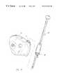
- FIG. 1is a perspective view illustrating a stubby antenna of this invention mounted on the handset of the communications device and removed therefrom;
- FIG. 2is a perspective view of the antenna of FIG. 1;
- FIG. 3is a partial exploded perspective view illustrating a retractable antenna having the snap-in connector of this invention included therein;
- FIG. 4is a partial vertical view of the antenna and handset of FIG. 3 with the antenna in its extended position;
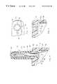
- FIG. 5is a top view of the upper portion of the handset
- FIG. 6is a partial vertical view of the upper portion of the handset
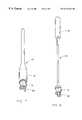
- FIG. 7is a perspective view of an antenna having the snap-in connector of this invention included therein;
- FIG. 8is a perspective view of a top-loaded retractable antenna having the snap-in connector of this invention included therein;
- FIG. 9is a perspective view of one form of the helical radiator employed in the embodiments disclosed herein with a spring contact extended downwardly therefrom;
- FIG. 10is a view similar to FIG. 9 except that the spring contact or spring arm is an integral part of the helical antenna.
- FIG. 1illustrates a conventional handset for a wireless communication device such as a cellular telephone and which is designated by the reference numeral 10 .
- Handset 10is conventional in design except for the opening 12 formed in the upper end of the housing 14 .
- the opening 12has an electrically conductive threaded connector provided therein which serves as the mounting for the antenna.
- the snap-in connector 16is inserted into the opening 12 , as will be described in more detailed hereinafter.
- FIGS. 1 and 2illustrate one form of the embodiment which is commonly referred to as a stubby antenna 18 which is a fixed antenna.
- the lower end of the stubby antenna 18is provided with the snap-in connector 16 to enable the antenna 18 to be quickly and easily installed in the opening 12 , as will be described in greater detail hereinafter.
- FIG. 3illustrates a collapsible or retractable antenna 20 having the snap-in connector 16 included therewith.
- FIG. 7illustrates a fixed antenna 22 having the snap-in connector 16 provided at the lower end thereof.
- the numeral 24refers to a top-loaded retractable antenna having the snap-in connector 16 associated therewith.
- the opening 12 in the housing 14is provided with an alignment keyway 26 which extends laterally outwardly from a pair of flat shoulders 28 and 30 which form a part of the alignment keyway.
- Connector 16includes a lower end portion 32 and an upper end portion 34 which are separated by an annular shoulder 36 which projects outwardly therefrom.
- Lower end portion 32is provided with an alignment key structure referred to generally by the reference numeral 38 which includes a pair of flat surfaces 40 and 42 having keyway 44 extending therefrom.
- Connector 16also includes a central bore 46 which extends therethrough, as illustrated in FIG. 4.
- a flexible or resilient latch 48is provided in the lower end 32 of connector 16 and includes a protruding latching lip 50 having a tapered lower surface 52 .
- the connector 16can only be inserted into the opening 12 in one position and that is extremely important in that it is ensured that the spring contact, to be described hereinafter, will be in the proper position with respect to the electrical contact pad of the receiving and transmitting circuitry of the communications device.
- the connector 16is inserted into the opening 12 so that the keyway 44 is received by the keyway 26 with the flat surfaces 40 and 42 being positioned adjacent the flat shoulders 28 and 30 , respectively.
- the latch 48is deflected inwardly through the engagement of the tapered surface 52 with the structure surrounding the opening 12 until the latch 50 is able to spring or move outwardly so as to engage an internal surface of the housing 14 , as illustrated in FIG. 4 .
- a helical radiator 54is positioned in the upper end of the bore 46 and has a spring contact 56 electrically connected to the lower end thereof. As seen in FIG. 4, the lower end of the spring contact 56 is in electrical contact with the electrical contact pad 58 positioned on the circuit board 60 of the receiving and transmitting circuitry.
- FIG. 9illustrates the spring contact 56 being a separate component from the radiator 54 .
- FIG. 10illustrates that the spring contact is in the form of a leg 62 which an integral part of the helical antenna or radiator 54 .
- the embodiment of FIG. 10is of unitary construction while the embodiment of FIG. 9 is of a two-piece construction.
- the numeral 64refers to an electrically conductive telescopic tube which is secured to the lower end of an elongated rod radiator or antenna 66 which is selectively vertically mounted so as to be able to be moved between a retracted position and an extended position.
- the lower end of the tube 64is in electrical contact with the spring contact 56 so that the radiator 66 is electrically connected to the contact pad 58 through the spring contact 56 .
- the spring contact 56through its engagement with the tube 64 , also serves to yieldably maintain the antenna in its extended position.
- the upper end of the connector 16is covered by a conventional coil cover 68 .
- a helical radiatorIn the stubby antenna configuration 18 of FIGS. 1 and 2, only a helical radiator is employed which may be either of the design of FIG. 9 or FIG. 10 .
- an elongated rod antenna or radiatoris secured to a helical radiator positioned within the cover 70 with the helical radiator and rod radiator being connected to the electrical contact pad 58 through the spring contact 56 , as previously described.
- the helical antennais enclosed within a cover 72 with the helical antenna being positioned at the upper end of the elongated radiator.
- the connector design 16is substantially similar in each of those designs.
- the connector 16does not have an upper end portion which supports the helical antenna, since the helical antenna is positioned at the upper end of the rod antenna.
- a novel antenna designhas been employed which includes a snap-in connector so that the antenna may be quickly and easily secured to the housing or removed therefrom.
- the design of this inventionensures that the proper electrical contact will be made inasmuch as the connector 16 can only be inserted into the housing in one position, with that one position ensuring that the spring contact 56 will be properly positioned with respect to the electrical contact pad 58 .
- the snap-in connector of this inventionresults in an antenna requiring less components without sacrificing reliability performance.
- the snap-in connector of this inventionresults in reduced manufacturing costs.
Landscapes
- Engineering & Computer Science (AREA)
- Computer Networks & Wireless Communication (AREA)
- Support Of Aerials (AREA)
Abstract
Description
Claims (21)
Priority Applications (1)
| Application Number | Priority Date | Filing Date | Title |
|---|---|---|---|
| US09/359,821US6215446B1 (en) | 1999-07-23 | 1999-07-23 | Snap-in antenna |
Applications Claiming Priority (1)
| Application Number | Priority Date | Filing Date | Title |
|---|---|---|---|
| US09/359,821US6215446B1 (en) | 1999-07-23 | 1999-07-23 | Snap-in antenna |
Publications (1)
| Publication Number | Publication Date |
|---|---|
| US6215446B1true US6215446B1 (en) | 2001-04-10 |
Family
ID=23415423
Family Applications (1)
| Application Number | Title | Priority Date | Filing Date |
|---|---|---|---|
| US09/359,821Expired - LifetimeUS6215446B1 (en) | 1999-07-23 | 1999-07-23 | Snap-in antenna |
Country Status (1)
| Country | Link |
|---|---|
| US (1) | US6215446B1 (en) |
Cited By (18)
| Publication number | Priority date | Publication date | Assignee | Title |
|---|---|---|---|---|
| WO2001067545A1 (en)* | 2000-03-07 | 2001-09-13 | Galtronics Usa, Inc. | Antenna connector |
| US6337669B1 (en)* | 2000-07-24 | 2002-01-08 | Auden Techno Corp. | Structure of multi-frequency antenna for a mobile phone |
| US6340955B1 (en)* | 2000-07-24 | 2002-01-22 | Auden Techno Corp. | Combining method for internal and external insulating sleeves of an antenna on a communication instrument |
| US6348896B2 (en)* | 1999-12-16 | 2002-02-19 | Matsushita Electric Industrial Co., Ltd. | Antenna device |
| US6441788B1 (en)* | 1999-08-24 | 2002-08-27 | Yokowo Co., Ltd. | Antenna attachment structure of a case |
| US20040119657A1 (en)* | 2002-12-23 | 2004-06-24 | Mayer Cheryl Ann | Stubby, multi-band, antenna having a large-diameter high frequency radiating/receiving element surrounding a small-diameter low frequency radiating/receiving element |
| US20040203516A1 (en)* | 2002-05-09 | 2004-10-14 | Tiao-Hsing Tsai | Mobile phone |
| EP1538693A1 (en)* | 2003-12-03 | 2005-06-08 | YOKOWO Co., Ltd | Structure for mounting antenna |
| EP1544942A1 (en)* | 2003-12-16 | 2005-06-22 | YOKOWO Co., Ltd | Fixing structure |
| EP1598899A1 (en)* | 2004-05-20 | 2005-11-23 | Lg Electronics Inc. | Antenna coupling structure for a mobile terminal |
| US20060079188A1 (en)* | 2004-10-12 | 2006-04-13 | Chintala Thomas J | Devices and methods for retaining an antenna |
| US20060215362A1 (en)* | 2005-03-09 | 2006-09-28 | Samsung Electronics Co., Ltd. | Portable electronic apparatus having a cooling device |
| US7400303B1 (en)* | 2003-10-21 | 2008-07-15 | R.A. Miller Industries, Inc. | Antenna with keyed coupling |
| US20080222877A1 (en)* | 2002-11-29 | 2008-09-18 | Research In Motion Limited | Combination of tube assembly and clip for wireless antenna grounding |
| US20080238809A1 (en)* | 2007-03-30 | 2008-10-02 | Motorola, Inc. | Flexible antenna mounting assembly |
| US20090213029A1 (en)* | 2005-04-14 | 2009-08-27 | Carles Puente Baliarda | Antenna contacting assembly |
| US8654031B2 (en) | 2010-09-28 | 2014-02-18 | Raytheon Company | Plug-in antenna |
| WO2016176372A1 (en)* | 2015-04-27 | 2016-11-03 | Osram Sylvania Inc. | Wireless mounted control module |
Citations (11)
| Publication number | Priority date | Publication date | Assignee | Title |
|---|---|---|---|---|
| US5243355A (en)* | 1991-03-04 | 1993-09-07 | Motorola, Inc. | Semiautomatic retractable antenna apparatus |
| US5353036A (en)* | 1991-07-13 | 1994-10-04 | Nokia Mobile Phones (U.K.) Limited | Dual antenna assembly with antenna retraction inactivation |
| US5479178A (en) | 1993-05-21 | 1995-12-26 | Samsung Electronics Co., Ltd. | Portable radio antenna |
| US5594457A (en) | 1995-04-21 | 1997-01-14 | Centurion International, Inc. | Retractable antenna |
| US5661495A (en) | 1993-05-24 | 1997-08-26 | Allgon Ab | Antenna device for portable equipment |
| US5852421A (en)* | 1996-04-02 | 1998-12-22 | Qualcomm Incorporated | Dual-band antenna coupler for a portable radiotelephone |
| US5856808A (en)* | 1997-09-29 | 1999-01-05 | Ericsson Inc. | Single feed point matching systems |
| US5880696A (en) | 1995-11-08 | 1999-03-09 | Nokia Mobile Phones Ltd. | Retractable antenna for a radio transmitting and receiving device |
| US6052089A (en)* | 1997-12-23 | 2000-04-18 | Nokia Mobile Phones Limited | Half-wave retractable antenna with matching helix |
| US6064341A (en)* | 1998-05-14 | 2000-05-16 | Motorola, Inc. | Antenna assembly |
| US6075487A (en)* | 1997-02-19 | 2000-06-13 | Sony Corporation | Portable telephone and antenna device |
- 1999
- 1999-07-23USUS09/359,821patent/US6215446B1/ennot_activeExpired - Lifetime
Patent Citations (11)
| Publication number | Priority date | Publication date | Assignee | Title |
|---|---|---|---|---|
| US5243355A (en)* | 1991-03-04 | 1993-09-07 | Motorola, Inc. | Semiautomatic retractable antenna apparatus |
| US5353036A (en)* | 1991-07-13 | 1994-10-04 | Nokia Mobile Phones (U.K.) Limited | Dual antenna assembly with antenna retraction inactivation |
| US5479178A (en) | 1993-05-21 | 1995-12-26 | Samsung Electronics Co., Ltd. | Portable radio antenna |
| US5661495A (en) | 1993-05-24 | 1997-08-26 | Allgon Ab | Antenna device for portable equipment |
| US5594457A (en) | 1995-04-21 | 1997-01-14 | Centurion International, Inc. | Retractable antenna |
| US5880696A (en) | 1995-11-08 | 1999-03-09 | Nokia Mobile Phones Ltd. | Retractable antenna for a radio transmitting and receiving device |
| US5852421A (en)* | 1996-04-02 | 1998-12-22 | Qualcomm Incorporated | Dual-band antenna coupler for a portable radiotelephone |
| US6075487A (en)* | 1997-02-19 | 2000-06-13 | Sony Corporation | Portable telephone and antenna device |
| US5856808A (en)* | 1997-09-29 | 1999-01-05 | Ericsson Inc. | Single feed point matching systems |
| US6052089A (en)* | 1997-12-23 | 2000-04-18 | Nokia Mobile Phones Limited | Half-wave retractable antenna with matching helix |
| US6064341A (en)* | 1998-05-14 | 2000-05-16 | Motorola, Inc. | Antenna assembly |
Cited By (37)
| Publication number | Priority date | Publication date | Assignee | Title |
|---|---|---|---|---|
| US6441788B1 (en)* | 1999-08-24 | 2002-08-27 | Yokowo Co., Ltd. | Antenna attachment structure of a case |
| US6348896B2 (en)* | 1999-12-16 | 2002-02-19 | Matsushita Electric Industrial Co., Ltd. | Antenna device |
| US6639561B2 (en) | 2000-03-07 | 2003-10-28 | Galtronics Ltd. | Antenna connector |
| WO2001067545A1 (en)* | 2000-03-07 | 2001-09-13 | Galtronics Usa, Inc. | Antenna connector |
| US6337669B1 (en)* | 2000-07-24 | 2002-01-08 | Auden Techno Corp. | Structure of multi-frequency antenna for a mobile phone |
| US6340955B1 (en)* | 2000-07-24 | 2002-01-22 | Auden Techno Corp. | Combining method for internal and external insulating sleeves of an antenna on a communication instrument |
| US20040203516A1 (en)* | 2002-05-09 | 2004-10-14 | Tiao-Hsing Tsai | Mobile phone |
| US8068060B2 (en) | 2002-11-29 | 2011-11-29 | Research In Motion Limited | Combination of tube assembly and clip for wireless antenna grounding |
| US20100220032A1 (en)* | 2002-11-29 | 2010-09-02 | Research In Motion Limited | Combination of tube assembly and clip for wireless antenna grounding |
| US7739784B2 (en)* | 2002-11-29 | 2010-06-22 | Research In Motion Limited | Method of making an antenna assembly |
| US20080222877A1 (en)* | 2002-11-29 | 2008-09-18 | Research In Motion Limited | Combination of tube assembly and clip for wireless antenna grounding |
| US20040119657A1 (en)* | 2002-12-23 | 2004-06-24 | Mayer Cheryl Ann | Stubby, multi-band, antenna having a large-diameter high frequency radiating/receiving element surrounding a small-diameter low frequency radiating/receiving element |
| US7400303B1 (en)* | 2003-10-21 | 2008-07-15 | R.A. Miller Industries, Inc. | Antenna with keyed coupling |
| EP1538693A1 (en)* | 2003-12-03 | 2005-06-08 | YOKOWO Co., Ltd | Structure for mounting antenna |
| US20050122275A1 (en)* | 2003-12-03 | 2005-06-09 | Yokowo Co., Ltd. | Structure for mounting antenna |
| US7046206B2 (en) | 2003-12-03 | 2006-05-16 | Yokowo Co., Ltd. | Structure for mounting antenna |
| EP1544942A1 (en)* | 2003-12-16 | 2005-06-22 | YOKOWO Co., Ltd | Fixing structure |
| US20050179613A1 (en)* | 2003-12-16 | 2005-08-18 | Yokowo Co., Ltd. | Fixing structure |
| US7250912B2 (en) | 2003-12-16 | 2007-07-31 | Yokowo Co., Ltd. | Fixing structure |
| US7221324B2 (en) | 2004-05-20 | 2007-05-22 | Lg Electronics Inc. | Antenna coupling structure for a mobile terminal |
| EP1598899A1 (en)* | 2004-05-20 | 2005-11-23 | Lg Electronics Inc. | Antenna coupling structure for a mobile terminal |
| EP2280446A1 (en)* | 2004-05-20 | 2011-02-02 | LG Electronics Inc. | Antenna coupling structure for a mobile terminal |
| US20050259014A1 (en)* | 2004-05-20 | 2005-11-24 | Lg Electronics Inc. | Antenna coupling structure for a mobile terminal |
| US20060079188A1 (en)* | 2004-10-12 | 2006-04-13 | Chintala Thomas J | Devices and methods for retaining an antenna |
| EP1962376A1 (en) | 2004-10-12 | 2008-08-27 | QUALCOMM Incorporated | Devices and methods for retaining an antenna |
| WO2006042325A1 (en)* | 2004-10-12 | 2006-04-20 | Qualcomm Incorporated | Devices and methods for retaining an antenna |
| US7486240B2 (en)* | 2004-10-12 | 2009-02-03 | Qualcomm Incorporated | Devices and methods for retaining an antenna |
| KR100891829B1 (en) | 2004-10-12 | 2009-04-07 | 콸콤 인코포레이티드 | Devices and methods for retaining an antenna |
| US7945288B2 (en)* | 2005-03-09 | 2011-05-17 | Samsung Electronics Co., Ltd. | Portable electronic apparatus having a cooling device |
| US20060215362A1 (en)* | 2005-03-09 | 2006-09-28 | Samsung Electronics Co., Ltd. | Portable electronic apparatus having a cooling device |
| US20090213029A1 (en)* | 2005-04-14 | 2009-08-27 | Carles Puente Baliarda | Antenna contacting assembly |
| US8193998B2 (en) | 2005-04-14 | 2012-06-05 | Fractus, S.A. | Antenna contacting assembly |
| US7796094B2 (en) | 2007-03-30 | 2010-09-14 | Motorola, Inc. | Flexible antenna mounting assembly |
| WO2008121523A3 (en)* | 2007-03-30 | 2008-12-24 | Motorola Inc | Flexible antenna mounting assembly |
| US20080238809A1 (en)* | 2007-03-30 | 2008-10-02 | Motorola, Inc. | Flexible antenna mounting assembly |
| US8654031B2 (en) | 2010-09-28 | 2014-02-18 | Raytheon Company | Plug-in antenna |
| WO2016176372A1 (en)* | 2015-04-27 | 2016-11-03 | Osram Sylvania Inc. | Wireless mounted control module |
Similar Documents
| Publication | Publication Date | Title |
|---|---|---|
| US6215446B1 (en) | Snap-in antenna | |
| EP0516490B1 (en) | Retractable antenna | |
| US6448932B1 (en) | Dual feed internal antenna | |
| KR900702592A (en) | Enhanced Extendable Antenna for Portable Cell Phones | |
| US6031493A (en) | Antenna for two frequency bands | |
| US20030083023A1 (en) | Antenna device of wireless phone | |
| US7904126B2 (en) | Antenna applied to slide type mobile communication terminal | |
| US6380900B1 (en) | Antenna apparatus and wireless communication apparatus | |
| US7639194B2 (en) | Dual-band loop antenna | |
| US20060244665A1 (en) | Antenna assembly for use in a portable telecommunication device | |
| JPH06188805A (en) | Radio equipment | |
| KR20140063188A (en) | Electronic device | |
| KR20010035712A (en) | Hand-phone and Battery for Hand-phone | |
| US7065379B1 (en) | Portable radio terminal equipment having conductor for preventing radiation loss | |
| KR100491884B1 (en) | Frequency Selective Surface painted antenna for a mobile phone | |
| KR100568270B1 (en) | Built-in antenna terminal support | |
| US5999133A (en) | Retractable antenna with shifting electrical length | |
| KR200366568Y1 (en) | Internal antenna for watch-type handset | |
| CA2293285A1 (en) | Antenna apparatus for use in mobile radio communication apparatus | |
| JP3415519B2 (en) | Helical antenna | |
| KR100631664B1 (en) | Internal antenna structure of portable terminal | |
| KR100372888B1 (en) | Monopole antenna for folder type phone to reduce SAR | |
| JP2001136012A (en) | Antenna device and mobile communication equipment provided with the antenna device | |
| KR200336071Y1 (en) | Built-in antennas and portable phone using thereof | |
| KR200160125Y1 (en) | Antenna connecting device for cordless telephone |
Legal Events
| Date | Code | Title | Description |
|---|---|---|---|
| AS | Assignment | Owner name:CENTURION INTERNATIONAL, INC., NEBRASKA Free format text:ASSIGNMENT OF ASSIGNORS INTEREST;ASSIGNORS:SULLIVAN, JONATHAN L.;HAUSSLER, BRADLEY L.;REEL/FRAME:010393/0404 Effective date:19990719 | |
| AS | Assignment | Owner name:CENTURION WIRELESS TECHNOLOGIES, INC., NEBRASKA Free format text:MERGER;ASSIGNOR:CENTURION INTERNATIONAL, INC.;REEL/FRAME:011284/0637 Effective date:20000920 Owner name:CENTURION WIRELESS TECHNOLOGIES, INC.,NEBRASKA Free format text:MERGER;ASSIGNOR:CENTURION INTERNATIONAL, INC.;REEL/FRAME:011284/0637 Effective date:20000920 | |
| STCF | Information on status: patent grant | Free format text:PATENTED CASE | |
| FPAY | Fee payment | Year of fee payment:4 | |
| FEPP | Fee payment procedure | Free format text:PAYOR NUMBER ASSIGNED (ORIGINAL EVENT CODE: ASPN); ENTITY STATUS OF PATENT OWNER: SMALL ENTITY | |
| FPAY | Fee payment | Year of fee payment:8 | |
| FEPP | Fee payment procedure | Free format text:PAT HOLDER CLAIMS SMALL ENTITY STATUS, ENTITY STATUS SET TO SMALL (ORIGINAL EVENT CODE: LTOS); ENTITY STATUS OF PATENT OWNER: SMALL ENTITY | |
| FEPP | Fee payment procedure | Free format text:ENTITY STATUS SET TO SMALL (ORIGINAL EVENT CODE: SMAL); ENTITY STATUS OF PATENT OWNER: SMALL ENTITY | |
| FPAY | Fee payment | Year of fee payment:12 | |
| AS | Assignment | Owner name:CENTURION INTERNATIONAL, INC., NEBRASKA Free format text:CORRECTIVE ASSIGNMENT TO CORRECT THE SECOND INVENTOR (BRADLEY S. HAUSSLER) MIDDLE INITIAL FROM L. TO S, PREVIOUSLY RECORDED ON REEL 010393 FRAME 0404L ASSIGNOR(S) HERBY CONFIRMS THE SECOND INVENTOR (BRADLEY S. HAUSSLER) MIDDLE INITIAL IS S;ASSIGNORS:SULLIVAN, JONATHAN L.;HAUSSLER, BRADLEY S.;REEL/FRAME:030601/0119 Effective date:19990719 | |
| AS | Assignment | Owner name:FIRST TECHNOLOGIES, LLC, MISSOURI Free format text:ASSIGNMENT OF ASSIGNORS INTEREST;ASSIGNOR:CENTURION WIRELESS TECHNOLOGIES, INC.;REEL/FRAME:030970/0544 Effective date:20130712 | |
| AS | Assignment | Owner name:SAMSUNG ELECTRONICS CO., LTD., KOREA, REPUBLIC OF Free format text:ASSIGNMENT OF ASSIGNORS INTEREST;ASSIGNOR:FIRST TECHNOLOGIES, LLC;REEL/FRAME:032714/0206 Effective date:20130726 |