US6215443B1 - Radar module and antenna device - Google Patents
Radar module and antenna deviceDownload PDFInfo
- Publication number
- US6215443B1 US6215443B1US09/356,226US35622699AUS6215443B1US 6215443 B1US6215443 B1US 6215443B1US 35622699 AUS35622699 AUS 35622699AUS 6215443 B1US6215443 B1US 6215443B1
- Authority
- US
- United States
- Prior art keywords
- antenna elements
- dielectric substrate
- transmitting
- planar array
- antenna
- Prior art date
- Legal status (The legal status is an assumption and is not a legal conclusion. Google has not performed a legal analysis and makes no representation as to the accuracy of the status listed.)
- Expired - Fee Related
Links
Images
Classifications
- H—ELECTRICITY
- H01—ELECTRIC ELEMENTS
- H01Q—ANTENNAS, i.e. RADIO AERIALS
- H01Q21/00—Antenna arrays or systems
- H01Q21/0006—Particular feeding systems
- G—PHYSICS
- G01—MEASURING; TESTING
- G01S—RADIO DIRECTION-FINDING; RADIO NAVIGATION; DETERMINING DISTANCE OR VELOCITY BY USE OF RADIO WAVES; LOCATING OR PRESENCE-DETECTING BY USE OF THE REFLECTION OR RERADIATION OF RADIO WAVES; ANALOGOUS ARRANGEMENTS USING OTHER WAVES
- G01S13/00—Systems using the reflection or reradiation of radio waves, e.g. radar systems; Analogous systems using reflection or reradiation of waves whose nature or wavelength is irrelevant or unspecified
- G01S13/88—Radar or analogous systems specially adapted for specific applications
- G01S13/93—Radar or analogous systems specially adapted for specific applications for anti-collision purposes
- G01S13/931—Radar or analogous systems specially adapted for specific applications for anti-collision purposes of land vehicles
- G—PHYSICS
- G01—MEASURING; TESTING
- G01S—RADIO DIRECTION-FINDING; RADIO NAVIGATION; DETERMINING DISTANCE OR VELOCITY BY USE OF RADIO WAVES; LOCATING OR PRESENCE-DETECTING BY USE OF THE REFLECTION OR RERADIATION OF RADIO WAVES; ANALOGOUS ARRANGEMENTS USING OTHER WAVES
- G01S7/00—Details of systems according to groups G01S13/00, G01S15/00, G01S17/00
- G01S7/02—Details of systems according to groups G01S13/00, G01S15/00, G01S17/00 of systems according to group G01S13/00
- G01S7/03—Details of HF subsystems specially adapted therefor, e.g. common to transmitter and receiver
- G01S7/032—Constructional details for solid-state radar subsystems
- H—ELECTRICITY
- H01—ELECTRIC ELEMENTS
- H01Q—ANTENNAS, i.e. RADIO AERIALS
- H01Q1/00—Details of, or arrangements associated with, antennas
- H01Q1/27—Adaptation for use in or on movable bodies
- H01Q1/32—Adaptation for use in or on road or rail vehicles
- H01Q1/3208—Adaptation for use in or on road or rail vehicles characterised by the application wherein the antenna is used
- H01Q1/3233—Adaptation for use in or on road or rail vehicles characterised by the application wherein the antenna is used particular used as part of a sensor or in a security system, e.g. for automotive radar, navigation systems
- H—ELECTRICITY
- H01—ELECTRIC ELEMENTS
- H01Q—ANTENNAS, i.e. RADIO AERIALS
- H01Q1/00—Details of, or arrangements associated with, antennas
- H01Q1/36—Structural form of radiating elements, e.g. cone, spiral, umbrella; Particular materials used therewith
- H01Q1/38—Structural form of radiating elements, e.g. cone, spiral, umbrella; Particular materials used therewith formed by a conductive layer on an insulating support
- H—ELECTRICITY
- H01—ELECTRIC ELEMENTS
- H01Q—ANTENNAS, i.e. RADIO AERIALS
- H01Q19/00—Combinations of primary active antenna elements and units with secondary devices, e.g. with quasi-optical devices, for giving the antenna a desired directional characteristic
- H01Q19/10—Combinations of primary active antenna elements and units with secondary devices, e.g. with quasi-optical devices, for giving the antenna a desired directional characteristic using reflecting surfaces
- H01Q19/12—Combinations of primary active antenna elements and units with secondary devices, e.g. with quasi-optical devices, for giving the antenna a desired directional characteristic using reflecting surfaces wherein the surfaces are concave
- H01Q19/13—Combinations of primary active antenna elements and units with secondary devices, e.g. with quasi-optical devices, for giving the antenna a desired directional characteristic using reflecting surfaces wherein the surfaces are concave the primary radiating source being a single radiating element, e.g. a dipole, a slot, a waveguide termination
- H01Q19/132—Horn reflector antennas; Off-set feeding
- H—ELECTRICITY
- H01—ELECTRIC ELEMENTS
- H01Q—ANTENNAS, i.e. RADIO AERIALS
- H01Q21/00—Antenna arrays or systems
- H01Q21/0006—Particular feeding systems
- H01Q21/0025—Modular arrays
- H—ELECTRICITY
- H01—ELECTRIC ELEMENTS
- H01Q—ANTENNAS, i.e. RADIO AERIALS
- H01Q21/00—Antenna arrays or systems
- H01Q21/06—Arrays of individually energised antenna units similarly polarised and spaced apart
- H01Q21/061—Two dimensional planar arrays
- H01Q21/065—Patch antenna array
- H—ELECTRICITY
- H01—ELECTRIC ELEMENTS
- H01Q—ANTENNAS, i.e. RADIO AERIALS
- H01Q21/00—Antenna arrays or systems
- H01Q21/06—Arrays of individually energised antenna units similarly polarised and spaced apart
- H01Q21/08—Arrays of individually energised antenna units similarly polarised and spaced apart the units being spaced along or adjacent to a rectilinear path
- H—ELECTRICITY
- H01—ELECTRIC ELEMENTS
- H01Q—ANTENNAS, i.e. RADIO AERIALS
- H01Q23/00—Antennas with active circuits or circuit elements integrated within them or attached to them
- H—ELECTRICITY
- H01—ELECTRIC ELEMENTS
- H01Q—ANTENNAS, i.e. RADIO AERIALS
- H01Q25/00—Antennas or antenna systems providing at least two radiating patterns
- G—PHYSICS
- G01—MEASURING; TESTING
- G01S—RADIO DIRECTION-FINDING; RADIO NAVIGATION; DETERMINING DISTANCE OR VELOCITY BY USE OF RADIO WAVES; LOCATING OR PRESENCE-DETECTING BY USE OF THE REFLECTION OR RERADIATION OF RADIO WAVES; ANALOGOUS ARRANGEMENTS USING OTHER WAVES
- G01S13/00—Systems using the reflection or reradiation of radio waves, e.g. radar systems; Analogous systems using reflection or reradiation of waves whose nature or wavelength is irrelevant or unspecified
- G01S13/87—Combinations of radar systems, e.g. primary radar and secondary radar
- G—PHYSICS
- G01—MEASURING; TESTING
- G01S—RADIO DIRECTION-FINDING; RADIO NAVIGATION; DETERMINING DISTANCE OR VELOCITY BY USE OF RADIO WAVES; LOCATING OR PRESENCE-DETECTING BY USE OF THE REFLECTION OR RERADIATION OF RADIO WAVES; ANALOGOUS ARRANGEMENTS USING OTHER WAVES
- G01S13/00—Systems using the reflection or reradiation of radio waves, e.g. radar systems; Analogous systems using reflection or reradiation of waves whose nature or wavelength is irrelevant or unspecified
- G01S13/88—Radar or analogous systems specially adapted for specific applications
- G01S13/93—Radar or analogous systems specially adapted for specific applications for anti-collision purposes
- G01S13/931—Radar or analogous systems specially adapted for specific applications for anti-collision purposes of land vehicles
- G01S2013/9321—Velocity regulation, e.g. cruise control
Definitions
- the present inventionrelates to a radar module and an antenna device for an FM millimeter-wave radar alarm system for use on motor vehicles.
- One known motor vehicle radar alarm systemhas an electronically scanning planar antenna array as disclosed in U.S. Pat. No. 5,008,678.
- the disclosed electronically scanning planar antenna arraycomprises a plurality of transmitting and receiving planar antenna elements, a pair of passive phased arrays such as planar microstrip Butler matrixes, and a pair of electronic switches which are combined to transmit and receive a scanning beam.
- the conventional electronically scanning planar antenna arrayis disadvantageous in that the passive phased arrays thereof cannot scan a relatively large angular range with the scanning beam. Another problem is that the planar antenna array requires both a transmitting array of antenna elements dedicated to transmitting radar signals and a receiving array of antenna elements dedicated to receiving echo signals. This imposes limitations on conventional systems which make it difficult to reduce the size of the planar antenna arrays used therein and, especially difficult to install such planar antenna arrays on motor vehicles.
- German laid-open publication No. 4307009discloses an antenna device for a radar module.
- Japanese patent publication No. 57-24968discloses a microwave IC case.
- Japanese laid-open utility model publication No. 1-126714discloses an antenna device.
- a radar modulecomprising a dielectric substrate, an antenna assembly mounted on the dielectric substrate, the antenna assembly comprising a plurality of transmitting and receiving channels including respective planar array antenna elements each composed of a plurality of patches connected to and spaced along a linear distal end portion of a feeder line, the planar array antenna elements being arrayed in a direction substantially perpendicular to the linear distal end portion of the feeder line, a plurality of transmitting and receiving assemblies mounted as monolithic microwave integrated circuits on the dielectric substrate, for selectively transmitting high-frequency signals to the planar array antenna elements and selectively receiving echo signals from the planar array antenna elements, and a plurality of circulators mounted on the dielectric substrate and associated with the transmitting and receiving channels, respectively, the circulators connecting the respective linear distal end portions of the feeder lines to transmission and reception end portions which are connected to the transmitting and receiving assemblies, respectively.
- the antenna assemblyserves as a primary radiator of a defocused multiple-beam antenna.
- the planar array antenna elementsare arranged to radiate respective electromagnetic waves at a predetermined tilt angle, the offset multiple-beam antenna having a secondary radiator positioned closely to the primary radiator.
- a radar modulecomprising a dielectric substrate, a plurality of planar array antenna elements mounted in respective channels on the dielectric substrate, and a plurality of monolithic microwave integrated circuits mounted on the dielectric substrate, the monolithic microwave integrated circuits including a plurality of transmitting assemblies for amplifying and supplying respective high-frequency signals to the planar array antenna elements, respectively, and a plurality of receiving assemblies for receiving echo signals from the planar array antenna elements and mixing the echo signals with amplified local signals related to the high-frequency signals.
- the planar array antenna elementsare divided into two groups, the planar array antenna elements of one of the two groups and the planar array antenna elements of the other of the two groups being arranged in an interdigitating pattern and disposed on respective linear distal end portions of feeder lines belonging to the respective groups and extending in opposite directions that are 180° apart from each other.
- planar array antenna elementsmay be divided into two groups, the planar array antenna elements of one of the two groups and the planar array antenna elements of the other of the two groups being disposed on respective linear distal end portions of feeder lines belonging to the respective groups and extending in opposite directions that are 180 apart from each other, and being positioned substantially in an end-to-end configuration and staggered with respect to each other in a direction across the feeder lines.
- the high-frequency signals transmitted to the planar array antenna elementscomprise frequency-modulated signals, the receiving assemblies including mixers for mixing echo signals from the planar array antenna elements with the frequency-modulated signals to thereby produce beat signals.
- the transmitting assembliesinclude transmission amplifiers for amplifying the high-frequency signals, and the receiving assemblies include reception amplifiers for amplifying the local signals.
- a control circuitis provided for selectively operating the transmission amplifiers and the reception amplifiers.
- an antenna devicecomprising a dielectric substrate, an array of antenna elements mounted on the dielectric substrate, each of the antenna elements comprising a plurality of patches interconnected in a direction transverse to the array, and a plurality of circulators mounted on the dielectric substrate and connected in series to the antenna elements, respectively.
- the circulatorsare arranged in adjacent pairs, the circulators in each of the pairs being arranged such that DC magnetic fields in mutually opposite directions are applied to the circulators, respectively, for rotating signals in mutually opposite directions in the circulators.
- the antenna devicefurther comprises a scanning control circuit for switching the antenna elements in a time-sharing fashion.
- an antenna devicecomprising a dielectric substrate, a primary radiator comprising an array of antenna elements mounted on the dielectric substrate, each of the antenna elements comprising a plurality of patches interconnected in a direction transverse to the array, and a plurality of circulators mounted on the dielectric substrate and connected in series to the antenna elements, respectively, a secondary radiator for reflecting a beam radiated from the antenna elements, and a holder supporting the primary radiator integrally with the secondary radiator, with the primary radiator being positioned substantially at a focal point of the secondary radiator.
- FIG. 1is a block diagram of an FM radar system which incorporates an FM radar module according to an embodiment of the present invention
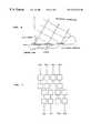
- FIG. 2is a plan view of the physical structure of the FM radar module shown in FIG. 1;
- FIG. 3is an enlarged plan view of one unit of transmitting and receiving channels of the FM radar module shown in FIG. 2;
- FIG. 4is a perspective view of a FM radar system which incorporates the FM radar module shown in FIG. 1;
- FIG. 5is a diagram showing distances to echo-generating objects that are detected by the FM radar system which incorporates the FM radar module shown in FIG. 1, together with a distribution of bearings covered by the FM radar system;
- FIG. 6is a diagram illustrative of a tilt angle of planar array antenna elements of the FM radar module shown in FIG. 2;
- FIG. 7is a plan view of a pattern of planar array antenna elements of an FM radar module according to another embodiment of the present invention.
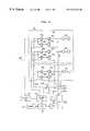
- FIG. 1shows in block form an FM radar system which incorporates an FM radar module according to an embodiment of the present invention.
- the FM radar systemgenerally comprises an FM radar module 10 and a main radar circuit 20 .
- the FM radar systemis preferably installed on a motor vehicle (not shown).
- the FM radar module 10comprises a dielectric substrate 11 having an antenna assembly 12 mounted thereon.
- the antenna assembly 12comprises a plurality ( 16 in the illustrated embodiment) of transmitting and receiving channels A ⁇ P disposed on the dielectric substrate 11 .
- the transmitting and receiving channels A ⁇ Pcomprise respective small-size planar array antenna elements 12 a ⁇ 12 p and respective transmitting and receiving assemblies.
- the small-size planar array antenna elements 12 a ⁇ 12 pare shared by the transmitting and receiving assemblies through respective circulators 14 a ⁇ 14 p which are connected in series with the planar array antenna elements 12 a ⁇ 12 p , respectively.
- the transmitting assembliesinclude respective selective transmission amplifiers 15 a ⁇ 15 p
- the receiving assembliesinclude respective selective reception amplifiers 16 a ⁇ 16 p and respective mixers 17 a ⁇ 17 p .
- the transmitting and receiving channels A ⁇ Preceive FM (frequency-modulated) signals to be transmitted which are supplied from an FM signal generator 23 in the main radar circuit 20 through a microstrip line MS.
- the main radar circuit 20comprises a CPU (central processing unit) 21 , a channel controller 22 , an FM signal generator 23 , a selector 24 , an A/D (analog-to-digital) converter 25 , an FFT (fast Fourier transform) circuit 26 , and a memory 27 .
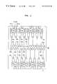
- the FM radar module 10 shown in FIG. 1has the physical structure illustrated in FIG. 2 .
- the dielectric substrate 11which is housed in a metallic casing, is made of highly pure alumina ceramic having a relative dielectric constant of 9.7, and supports thereon a plurality of (8 in the illustrated embodiment) MMICs (monolithic microwave integrated circuits) 13 a ⁇ 13 h.
- the 16 planar array antenna elements 12 a ⁇ 12 p and the corresponding transmitting and receiving channels A ⁇ P including the circulators 14 a ⁇ 14 pare divided into two groups. Specifically, the 16 planar array antenna elements 12 a ⁇ 12 p are divided into a group of eight planar array antenna elements 12 a ⁇ 12 h and a group of eight planar array antenna elements 12 i ⁇ 12 p .
- the eight planar array antenna elements 12 a ⁇ 12 h of one group and the eight planar array antenna elements 12 i ⁇ 12 p of the other groupare arranged in interdigitating pattern and disposed on respective linear distal end portions of feeder lines belonging to the respective groups and extending in opposite directions that are 180° apart from each other.
- the planar array antenna elements 12 a ⁇ 12 hare arrayed in a direction perpendicular to the linear distal end portions of the feeder lines.
- Each of the eight MMICs 13 a ⁇ 13 his composed of the transmitting and receiving assemblies of two adjacent transmitting and receiving channels of the 16 transmitting and receiving channels A ⁇ P.
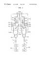
- the MMIC 13 a shown in FIG. 3is composed of the selective transmission amplifier 15 a , the selective reception amplifier 16 a , and the mixer 17 a which belong to the transmitting and receiving assembly of the transmitting and receiving channel A, and the selective transmission amplifier 15 b , the selective reception amplifier 16 b , and the mixer 17 b which belong to the transmitting and receiving assembly of the transmitting and receiving channel B.
- the planar array antenna 12 awhich is composed of rectangular patches P a 1 , P a 2 , of the transmitting and receiving channel A is connected to the linear distal end portion of a feeder line FLa, whose proximal end portion is divided into a transmission end portion TXOUT and a reception end portion RXIN by the circulator 14 a .
- the rectangular patches P a 1 , P a 2are spaced a certain distance along the linear distal end portion of the feeder line FLa.
- the transmission end portion TXOUT separated by the circulator 14 ais connected through the selective transmission amplifier 15 a to an input terminal TXIN of the MMIC 13 a for receiving an FM signal from the FM signal generator 23 .
- the reception end portion RXIN separated by the circulator 14 ais connected to an input terminal, i.e., a received signal input terminal, of the mixer 17 a .
- the other input terminal, i.e., a local oscillator input terminal, of the mixer 17 ais selectively supplied with an FM signal from the input terminal TXIN through the selective reception amplifier 16 a.
- the planar array antenna 12 bwhich is composed of rectangular patches P b 1 , P b 2 , of the transmitting and receiving channel B is connected to the linear distal end portion of a feeder line FLb, whose proximal end portion is divided into a transmission end portion TXOUT and a reception end portion RXIN by the circulator 14 b .
- the transmission end portion TXOUT separated by the circulator 14 bis connected through the selective transmission amplifier 15 b to the input terminal TXIN of the MMIC 13 a for receiving an FM signal from the FM signal generator 23 .
- the reception end portion RXIN separated by the circulator 14 bis connected to an input terminal of the mixer 17 b .
- the other input terminal of the mixer 17 bis selectively supplied with an FM signal from the input terminal TXIN through the selective reception amplifier 16 b.
- the selective transmission amplifiers 15 a , 15 b and the selective transmission amplifiers 16 a , 16 b of the transmitting and receiving channels A, Bare composed mainly of high-frequency FETs (field-effect transistors). These four selective amplifiers 15 a , 15 b , 16 a , 16 b intermittently amplify supplied input signals in response to respective intermittent drain voltages V d 1 ⁇ V d 4 selectively supplied from the channel controller 22 of the main radar circuit 20 .
- the four selective amplifiers 15 a , 15 b , 16 a , 16 bare also supplied with a constant gate voltage Vg.
- DC magnetic fields in mutually opposite directionsare applied to the circulators 14 a , 14 b , respectively, for rotating signals in mutually opposite directions in the circulators 14 a , 14 b .
- the application of DC magnetic fields in mutually opposite directions to the circulators 14 a , 14 bis effective to cancel those DC magnetic fields and prevent a DC magnetic field from being generated.
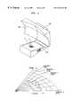
- FIG. 4illustrates in perspective an FM radar system which incorporates the FM radar module 10 shown in FIG. 1 .
- the FM radar module 10is housed in a metallic holder 40 and integrally combined with a secondary radiator 30 by the metallic holder 40 , with the antenna assembly 12 serving as a primary radiator.
- the secondary radiator 30has a parabolic reflecting surface 30 a
- the antenna assembly 12composed of the 16 planar array antenna elements 12 a ⁇ 12 p is positioned in the vicinity of the focal point of the parabolic reflecting surface 30 a .
- FM signals in a millimeter wavelength range which are radiated from the respective planar array antenna elements 12 a ⁇ 12 pare reflected by the parabolic reflecting surface 30 a and radiated at respective different angles or bearings in a horizontal direction forwardly of the secondary radiator 30 .
- the primary radiator composed of the antenna assembly 12 and the secondary radiator 30jointly make up an offset multiple-beam parabolic antenna.
- each of the planar array antenna elements 12 a ⁇ 12 pthe two rectangular patches are spaced a certain distance from each other along the linear distal end portion of the feeder line. Electromagnetic waves are radiated at a certain tilt angle from the respective planar array antenna elements 12 a ⁇ 12 p . Specifically, as shown in FIG.
- the direction (indicated by the solid lines) in which the electromagnetic waves are radiated from the respective patchesis inclined at a tilt angle relative to a line (indicated as the dot-and-dash line) normal to the dielectric substrate 11 such that equiphase surfaces (indicated by the dotted lines) of the electromagnetic waves radiated from the respective patches lie perpendicularly to the direction in which they are radiated from the respective patches.
- the equiphase surfaces of the radiated electromagnetic wavesare determined by a delay time which is caused when the signals are propagated through the feeder lines and the electromagnetic waves are propagated through the air.
- the length of the feeder line portion that interconnects the two patches of each of the eight planar array antenna elements of one groupis substantially a half wavelength different from the length of the feeder line portion that interconnects the two patches of each of the eight planar array antenna elements of the other group so that the electromagnetic waves will be radiated from the planar array antenna elements of the two groups at the same angle toward the secondary radiator.
- the FM radar module 10which is large in size, when compared with the primary radiator, is effectively prevented from interfering with the electromagnetic waves radiated from the secondary radiator 30 . Accordingly, the FM radar module 10 that includes the antenna assembly 12 as the primary radiator can be positioned near the secondary radiator 30 . With this arrangement, the FM radar module 10 is allowed to be of an MMIC-based structure which is made up of the MMICs 13 a ⁇ 13 h composed of the transmitting and receiving assemblies and the antenna assembly 12 on the dielectric substrate 11 .
- the FM millimeter-wave signals supplied from the FM signal generator 23are selectively amplified only in given periods successively by the respective selective transmission amplifiers 15 a ⁇ 15 p in the respective transmitting and receiving channels A ⁇ P according to channel control signals supplied from the channel controller 22 .
- Each of the selective transmission amplifiers 15 a ⁇ 15 pcomprises two cascaded FETs and switching transistors for intermittently supplying an operating drain voltage to the FETs according to the channel control signal, and selectively amplifies the FM millimeter-wave signal only in a period in which operating electric energy is supplied thereto.
- each of the selective transmission amplifiers 15 a ⁇ 15 pimparts a large insertion loss to the FM millimeter-wave signal passing therethrough, virtually separating the FM signal generator 23 and the corresponding one of the circulators 14 a ⁇ 14 p . Therefore, each of the selective transmission amplifiers 15 a ⁇ 15 p functions as a switch having such a gain for selectively connecting the FM signal generator 23 to and disconnecting the FM signal generator 23 from the corresponding one of the circulators 14 a ⁇ 14 p .
- the FM millimeter-wave signals amplified by the respective selective transmission amplifiers 15 a 15 pare supplied through the respective circulators 14 a ⁇ 14 p to the respective planar array antenna elements 12 a ⁇ 12 p , which then radiate the FM millimeter-wave signals as electromagnetic waves away from the dielectric substrate 11 toward the secondary radiator 30 (see FIG. 4 ).
- the radiated electromagnetic wavesare reflected by the parabolic reflecting surface 30 a of the secondary radiator 30 out of the motor vehicle on which the FM radar system is installed.
- Some of the FM millimeter-wave signals radiated as electromagnetic waves out of the motor vehicleare reflected by objects, travel back to and are received by the planar array antenna elements 12 a ⁇ 12 p .
- the reflected electromagnetic waves which are received by the planar array antenna elements 12 a ⁇ 12 pare separated as FM echo signals from the transmitting channels by the circulators 14 a ⁇ 14 p , respectively.
- the separated FM echo signalsare supplied to the respective received signal input terminals of the mixers 17 a ⁇ 17 p .
- the other local oscillator input terminals of the mixers 17 a ⁇ 17 pare supplied with amplified FM millimeter-wave signals from the selective reception amplifiers 16 a ⁇ 16 p which successively amplify FM millimeter-wave signals intermittently only in given periods according to channel control signals supplied from the channel controller 22 .
- the selective reception amplifiers 16 a ⁇ 16 pfunction as respective switches as was the case with the selective transmission amplifiers 15 a ⁇ 15 p.
- Beat signals outputted from respective output terminals of the mixers 17 a ⁇ 17 pare transmitted through output terminals BTa, BTb to the selector 24 .
- the beat signalsare amplified by respective amplifiers 24 a ⁇ 24 b whose amplification factor varies depending on the frequency.
- the amplifiers 24 a ⁇ 24 bare selected in a time-sharing fashion by the channel controller 22 to supply the amplified beat signals through a coaxial cable to the A/D converter 25 , which converts the beat signals into digital beat signals.
- the digital beat signalsare then supplied to the FFT circuit 26 , and converted thereby into a frequency spectrum that is then supplied to the CPU 21 .
- the CPU 21analyzes the frequency spectrum of the received FM echo signals supplied from the FFT circuit 26 , and calculates distances to the objects which have produced the FM echo signals in the respective transmitting and receiving channels and hence at respective bearings. Typically, the CPU 21 generates a two-dimensional map of obstacles to the motor vehicle as shown in FIG. 5 .
- FIG. 7shows in plan a pattern of planar array antenna elements of an FM radar module according to another embodiment of the present invention.
- eight planar array antenna elements 12 a ⁇ 12 hare divided into a group of four planar array antenna elements 12 a ⁇ 12 d and a group of four planar array antenna elements 12 e ⁇ 12 h .
- the four planar array antenna elements 12 a ⁇ 12 d of one group and the four planar array antenna elements 12 e ⁇ 12 h of the other groupare disposed on respective linear distal end portions of feeder lines belonging to the respective groups and extending in opposite directions that are 180° apart from each other.
- the four planar array antenna elements 12 a ⁇ 12 d and the four planar array antenna elements 12 e ⁇ 12 hare positioned substantially in an end-to-end configuration, but are staggered with respect to each other in a direction across the feeder lines, i.e., are held out of alignment with each other in a direction along the feeder lines. This arrangement permits the planar array antenna elements to be transversely spaced at relatively small intervals for small antenna size and high bearing resolution.
- the present inventionhas been described above as being embodied as an FM radar module. However, the principles of the present invention are also applicable to any of various other radar modules including an AM radar module, a pulse radar module, etc.
- a voltage-controlled oscillator of 60 GHzmay be mounted in the form of an MMIC on the dielectric substrate 11 , or included in each of the MMICs 13 a 13 h on the dielectric substrate 11 for lower cost and smaller size.
- the FM radar module according to the present inventionoffers the following various advantages: Since the plurality of small-size planar array antenna elements are arrayed so as to be shared by the transmitting and receiving assemblies through the circulators, the number of planar array antenna elements may be increased in a limited installation space, making it possible to scan a relatively large angular range with a scanning beam.
- the planar array antenna elementsserve as a primary radiator in an offset defocused multiple-beam parabolic antenna for wide scanning angular range and high bearing resolution.
- the various components of the antenna assembly 12are mounted in a high-density configuration. Specifically, the selective transmission and reception amplifiers and the mixers in the form of MMICs are mounted on the single dielectric substrate, making up the antenna assembly 12 serving as the primary radiator.
- An FM radar system of the scanning typewhich incorporates the antenna assembly 12 is of a high-density structure, a small size, a low cost, and high resolution, suitable for use on motor vehicles. The FM radar system can be used in a wide range of motor vehicle applications including an active cruise control system, a collision prevention system, etc.
Landscapes
- Engineering & Computer Science (AREA)
- Radar, Positioning & Navigation (AREA)
- Remote Sensing (AREA)
- Physics & Mathematics (AREA)
- Computer Networks & Wireless Communication (AREA)
- General Physics & Mathematics (AREA)
- Computer Security & Cryptography (AREA)
- Electromagnetism (AREA)
- Radar Systems Or Details Thereof (AREA)
- Variable-Direction Aerials And Aerial Arrays (AREA)
- Details Of Aerials (AREA)
Abstract
Description
This application is a continuation of U.S. patent application, Ser. No. 08/927,994, filed on Sep. 12, 1997, now U.S. Pat. No. 5,995,049, which is a divisional of U.S. patent application, Ser. No. 08/611,665, filed on Mar. 6, 1996, now U.S. Pat. No. 5,724,042, the disclosure of which are incorporated herein by reference.
1. Field of the Invention
The present invention relates to a radar module and an antenna device for an FM millimeter-wave radar alarm system for use on motor vehicles.
2. Description of the Prior Art
One known motor vehicle radar alarm system has an electronically scanning planar antenna array as disclosed in U.S. Pat. No. 5,008,678. The disclosed electronically scanning planar antenna array comprises a plurality of transmitting and receiving planar antenna elements, a pair of passive phased arrays such as planar microstrip Butler matrixes, and a pair of electronic switches which are combined to transmit and receive a scanning beam.
The conventional electronically scanning planar antenna array is disadvantageous in that the passive phased arrays thereof cannot scan a relatively large angular range with the scanning beam. Another problem is that the planar antenna array requires both a transmitting array of antenna elements dedicated to transmitting radar signals and a receiving array of antenna elements dedicated to receiving echo signals. This imposes limitations on conventional systems which make it difficult to reduce the size of the planar antenna arrays used therein and, especially difficult to install such planar antenna arrays on motor vehicles.
German laid-open publication No. 4307009 discloses an antenna device for a radar module.
IEEE TRANSACTIONS ON MICROWAVE THEORY AND TECHNIQUES, VOL. MTT-26, NO. 1, JANUARY 1978, shows an MIC Doppler module with output radiation normal to the substrate plane.
Japanese patent publication No. 57-24968 discloses a microwave IC case.
Japanese laid-open utility model publication No. 1-126714 discloses an antenna device.
It is an object of the present invention to provide a radar module and an antenna device which are capable of scanning a relatively large angular range with a scanning beam and which are of a small size suitable for use particularly on motor vehicles.
According to one aspect of the present invention, there is provided a radar module comprising a dielectric substrate, an antenna assembly mounted on the dielectric substrate, the antenna assembly comprising a plurality of transmitting and receiving channels including respective planar array antenna elements each composed of a plurality of patches connected to and spaced along a linear distal end portion of a feeder line, the planar array antenna elements being arrayed in a direction substantially perpendicular to the linear distal end portion of the feeder line, a plurality of transmitting and receiving assemblies mounted as monolithic microwave integrated circuits on the dielectric substrate, for selectively transmitting high-frequency signals to the planar array antenna elements and selectively receiving echo signals from the planar array antenna elements, and a plurality of circulators mounted on the dielectric substrate and associated with the transmitting and receiving channels, respectively, the circulators connecting the respective linear distal end portions of the feeder lines to transmission and reception end portions which are connected to the transmitting and receiving assemblies, respectively.
The antenna assembly serves as a primary radiator of a defocused multiple-beam antenna. The planar array antenna elements are arranged to radiate respective electromagnetic waves at a predetermined tilt angle, the offset multiple-beam antenna having a secondary radiator positioned closely to the primary radiator.
According to another aspect of the present invention, there is also provided a radar module comprising a dielectric substrate, a plurality of planar array antenna elements mounted in respective channels on the dielectric substrate, and a plurality of monolithic microwave integrated circuits mounted on the dielectric substrate, the monolithic microwave integrated circuits including a plurality of transmitting assemblies for amplifying and supplying respective high-frequency signals to the planar array antenna elements, respectively, and a plurality of receiving assemblies for receiving echo signals from the planar array antenna elements and mixing the echo signals with amplified local signals related to the high-frequency signals.
In each of the above radar modules, the planar array antenna elements are divided into two groups, the planar array antenna elements of one of the two groups and the planar array antenna elements of the other of the two groups being arranged in an interdigitating pattern and disposed on respective linear distal end portions of feeder lines belonging to the respective groups and extending in opposite directions that are 180° apart from each other.
Alternatively, the planar array antenna elements may be divided into two groups, the planar array antenna elements of one of the two groups and the planar array antenna elements of the other of the two groups being disposed on respective linear distal end portions of feeder lines belonging to the respective groups and extending in opposite directions that are 180 apart from each other, and being positioned substantially in an end-to-end configuration and staggered with respect to each other in a direction across the feeder lines.
The high-frequency signals transmitted to the planar array antenna elements comprise frequency-modulated signals, the receiving assemblies including mixers for mixing echo signals from the planar array antenna elements with the frequency-modulated signals to thereby produce beat signals.
The transmitting assemblies include transmission amplifiers for amplifying the high-frequency signals, and the receiving assemblies include reception amplifiers for amplifying the local signals. A control circuit is provided for selectively operating the transmission amplifiers and the reception amplifiers.
According to still another aspect of the present invention, there is also provided an antenna device comprising a dielectric substrate, an array of antenna elements mounted on the dielectric substrate, each of the antenna elements comprising a plurality of patches interconnected in a direction transverse to the array, and a plurality of circulators mounted on the dielectric substrate and connected in series to the antenna elements, respectively.
The circulators are arranged in adjacent pairs, the circulators in each of the pairs being arranged such that DC magnetic fields in mutually opposite directions are applied to the circulators, respectively, for rotating signals in mutually opposite directions in the circulators.
The antenna device further comprises a scanning control circuit for switching the antenna elements in a time-sharing fashion.
According to still another aspect of the present invention, there is provided an antenna device comprising a dielectric substrate, a primary radiator comprising an array of antenna elements mounted on the dielectric substrate, each of the antenna elements comprising a plurality of patches interconnected in a direction transverse to the array, and a plurality of circulators mounted on the dielectric substrate and connected in series to the antenna elements, respectively, a secondary radiator for reflecting a beam radiated from the antenna elements, and a holder supporting the primary radiator integrally with the secondary radiator, with the primary radiator being positioned substantially at a focal point of the secondary radiator.
The above and other objects, features, and advantages of the present invention will become apparent from the following description when viewed in conjunction with the accompanying drawings which illustrate, by way of example, preferred embodiments of the present invention.
FIG. 1 is a block diagram of an FM radar system which incorporates an FM radar module according to an embodiment of the present invention;
FIG. 2 is a plan view of the physical structure of the FM radar module shown in FIG. 1;
FIG. 3 is an enlarged plan view of one unit of transmitting and receiving channels of the FM radar module shown in FIG. 2;
FIG. 4 is a perspective view of a FM radar system which incorporates the FM radar module shown in FIG. 1;
FIG. 5 is a diagram showing distances to echo-generating objects that are detected by the FM radar system which incorporates the FM radar module shown in FIG. 1, together with a distribution of bearings covered by the FM radar system;
FIG. 6 is a diagram illustrative of a tilt angle of planar array antenna elements of the FM radar module shown in FIG. 2; and
FIG. 7 is a plan view of a pattern of planar array antenna elements of an FM radar module according to another embodiment of the present invention.
FIG. 1 shows in block form an FM radar system which incorporates an FM radar module according to an embodiment of the present invention.
As shown in FIG. 1, the FM radar system generally comprises anFM radar module 10 and amain radar circuit 20. The FM radar system is preferably installed on a motor vehicle (not shown).
TheFM radar module 10 comprises adielectric substrate 11 having anantenna assembly 12 mounted thereon. Theantenna assembly 12 comprises a plurality (16 in the illustrated embodiment) of transmitting and receiving channels A˜P disposed on thedielectric substrate 11. The transmitting and receiving channels A˜P comprise respective small-size planararray antenna elements 12a˜12pand respective transmitting and receiving assemblies. The small-size planararray antenna elements 12a˜12pare shared by the transmitting and receiving assemblies throughrespective circulators 14a˜14pwhich are connected in series with the planararray antenna elements 12a˜12p, respectively. The transmitting assemblies include respectiveselective transmission amplifiers 15a˜15p, and the receiving assemblies include respectiveselective reception amplifiers 16a˜16pandrespective mixers 17a˜17p. The transmitting and receiving channels A˜P receive FM (frequency-modulated) signals to be transmitted which are supplied from anFM signal generator 23 in themain radar circuit 20 through a microstrip line MS.
Themain radar circuit 20 comprises a CPU (central processing unit)21, achannel controller 22, anFM signal generator 23, aselector 24, an A/D (analog-to-digital)converter 25, an FFT (fast Fourier transform)circuit 26, and amemory 27.
TheFM radar module 10 shown in FIG. 1 has the physical structure illustrated in FIG.2. Thedielectric substrate 11, which is housed in a metallic casing, is made of highly pure alumina ceramic having a relative dielectric constant of 9.7, and supports thereon a plurality of (8 in the illustrated embodiment) MMICs (monolithic microwave integrated circuits)13a˜13h.
In order for theFM radar module 10 to provide an installation space for the16circulators 14a˜14pwhich are relatively large in size, the16 planararray antenna elements 12a˜12pand the corresponding transmitting and receiving channels A˜P including thecirculators 14a˜14pare divided into two groups. Specifically, the16 planararray antenna elements 12a˜12pare divided into a group of eight planararray antenna elements 12a˜12hand a group of eight planararray antenna elements 12i˜12p. The eight planararray antenna elements 12a˜12hof one group and the eight planararray antenna elements 12i˜12pof the other group are arranged in interdigitating pattern and disposed on respective linear distal end portions of feeder lines belonging to the respective groups and extending in opposite directions that are 180° apart from each other. The planararray antenna elements 12a˜12hare arrayed in a direction perpendicular to the linear distal end portions of the feeder lines.
Each of the eightMMICs 13a˜13his composed of the transmitting and receiving assemblies of two adjacent transmitting and receiving channels of the16 transmitting and receiving channels A˜P. For example, theMMIC 13a shown in FIG. 3 is composed of theselective transmission amplifier 15a, theselective reception amplifier 16a, and themixer 17awhich belong to the transmitting and receiving assembly of the transmitting and receiving channel A, and theselective transmission amplifier 15b, theselective reception amplifier 16b, and themixer 17bwhich belong to the transmitting and receiving assembly of the transmitting and receiving channel B.
Theplanar array antenna 12a, which is composed ofrectangular patches Pa 1,Pa 2, of the transmitting and receiving channel A is connected to the linear distal end portion of a feeder line FLa, whose proximal end portion is divided into a transmission end portion TXOUT and a reception end portion RXIN by the circulator14a. Therectangular patches Pa 1,Pa 2 are spaced a certain distance along the linear distal end portion of the feeder line FLa. The transmission end portion TXOUT separated by the circulator14ais connected through theselective transmission amplifier 15ato an input terminal TXIN of theMMIC 13afor receiving an FM signal from theFM signal generator 23. The reception end portion RXIN separated by the circulator14ais connected to an input terminal, i.e., a received signal input terminal, of themixer 17a. The other input terminal, i.e., a local oscillator input terminal, of themixer 17ais selectively supplied with an FM signal from the input terminal TXIN through theselective reception amplifier 16a.
Similarly, theplanar array antenna 12b, which is composed ofrectangular patches Pb 1,Pb 2, of the transmitting and receiving channel B is connected to the linear distal end portion of a feeder line FLb, whose proximal end portion is divided into a transmission end portion TXOUT and a reception end portion RXIN by thecirculator 14b. The transmission end portion TXOUT separated by thecirculator 14bis connected through theselective transmission amplifier 15bto the input terminal TXIN of theMMIC 13afor receiving an FM signal from theFM signal generator 23. The reception end portion RXIN separated by thecirculator 14bis connected to an input terminal of themixer 17b. The other input terminal of themixer 17bis selectively supplied with an FM signal from the input terminal TXIN through theselective reception amplifier 16b.
Theselective transmission amplifiers selective transmission amplifiers selective amplifiers channel controller 22 of themain radar circuit 20. The fourselective amplifiers
DC magnetic fields in mutually opposite directions are applied to thecirculators circulators circulators
FIG. 4 illustrates in perspective an FM radar system which incorporates theFM radar module 10 shown in FIG.1. As shown in FIG. 4, theFM radar module 10 is housed in ametallic holder 40 and integrally combined with asecondary radiator 30 by themetallic holder 40, with theantenna assembly 12 serving as a primary radiator. Thesecondary radiator 30 has a parabolic reflectingsurface 30a, and theantenna assembly 12 composed of the16 planararray antenna elements 12a˜12pis positioned in the vicinity of the focal point of the parabolic reflectingsurface 30a. FM signals in a millimeter wavelength range which are radiated from the respective planararray antenna elements 12a˜12pare reflected by the parabolic reflectingsurface 30aand radiated at respective different angles or bearings in a horizontal direction forwardly of thesecondary radiator 30. The primary radiator composed of theantenna assembly 12 and thesecondary radiator 30 jointly make up an offset multiple-beam parabolic antenna.
In each of the planararray antenna elements 12a˜12p, the two rectangular patches are spaced a certain distance from each other along the linear distal end portion of the feeder line. Electromagnetic waves are radiated at a certain tilt angle from the respective planararray antenna elements 12a˜12p. Specifically, as shown in FIG. 6, the direction (indicated by the solid lines) in which the electromagnetic waves are radiated from the respective patches is inclined at a tilt angle relative to a line (indicated as the dot-and-dash line) normal to thedielectric substrate 11 such that equiphase surfaces (indicated by the dotted lines) of the electromagnetic waves radiated from the respective patches lie perpendicularly to the direction in which they are radiated from the respective patches. The equiphase surfaces of the radiated electromagnetic waves are determined by a delay time which is caused when the signals are propagated through the feeder lines and the electromagnetic waves are propagated through the air.
While the patches are shown thicker than the feeder line in FIG. 6 for distinguishing the patches from the feeder line, they are so shown for illustrative purpose only and are actually of the same thickness. The length of the feeder line portion that interconnects the two patches of each of the eight planar array antenna elements of one group is substantially a half wavelength different from the length of the feeder line portion that interconnects the two patches of each of the eight planar array antenna elements of the other group so that the electromagnetic waves will be radiated from the planar array antenna elements of the two groups at the same angle toward the secondary radiator.
As shown in FIG. 4, since each of the planararray antenna elements 12a˜12pradiates the electromagnetic wave at a tilt angle, as described above, theFM radar module 10 which is large in size, when compared with the primary radiator, is effectively prevented from interfering with the electromagnetic waves radiated from thesecondary radiator 30. Accordingly, theFM radar module 10 that includes theantenna assembly 12 as the primary radiator can be positioned near thesecondary radiator 30. With this arrangement, theFM radar module 10 is allowed to be of an MMIC-based structure which is made up of theMMICs 13a˜13hcomposed of the transmitting and receiving assemblies and theantenna assembly 12 on thedielectric substrate 11.
Referring back to FIG. 1, the FM millimeter-wave signals supplied from theFM signal generator 23 are selectively amplified only in given periods successively by the respectiveselective transmission amplifiers 15a˜15pin the respective transmitting and receiving channels A˜P according to channel control signals supplied from thechannel controller 22. Each of theselective transmission amplifiers 15a˜15pcomprises two cascaded FETs and switching transistors for intermittently supplying an operating drain voltage to the FETs according to the channel control signal, and selectively amplifies the FM millimeter-wave signal only in a period in which operating electric energy is supplied thereto.
More specifically, unless a drain voltage is supplied, each of theselective transmission amplifiers 15a˜15pimparts a large insertion loss to the FM millimeter-wave signal passing therethrough, virtually separating theFM signal generator 23 and the corresponding one of thecirculators 14a˜14p. Therefore, each of theselective transmission amplifiers 15a˜15pfunctions as a switch having such a gain for selectively connecting theFM signal generator 23 to and disconnecting theFM signal generator 23 from the corresponding one of thecirculators 14a˜14p. The FM millimeter-wave signals amplified by the respectiveselective transmission amplifiers 15a15pare supplied through therespective circulators 14a˜14pto the respective planararray antenna elements 12a˜12p, which then radiate the FM millimeter-wave signals as electromagnetic waves away from thedielectric substrate 11 toward the secondary radiator30 (see FIG.4). The radiated electromagnetic waves are reflected by the parabolic reflectingsurface 30a of thesecondary radiator 30 out of the motor vehicle on which the FM radar system is installed.
Some of the FM millimeter-wave signals radiated as electromagnetic waves out of the motor vehicle are reflected by objects, travel back to and are received by the planararray antenna elements 12a˜12p. The reflected electromagnetic waves which are received by the planararray antenna elements 12a˜12pare separated as FM echo signals from the transmitting channels by thecirculators 14a˜14p, respectively. The separated FM echo signals are supplied to the respective received signal input terminals of themixers 17a˜17p. The other local oscillator input terminals of themixers 17a˜17pare supplied with amplified FM millimeter-wave signals from theselective reception amplifiers 16a˜16pwhich successively amplify FM millimeter-wave signals intermittently only in given periods according to channel control signals supplied from thechannel controller 22. Theselective reception amplifiers 16a˜16pfunction as respective switches as was the case with theselective transmission amplifiers 15a˜15p.
Beat signals outputted from respective output terminals of themixers 17a˜17pare transmitted through output terminals BTa, BTb to theselector 24. In theselector 24, the beat signals are amplified by respective amplifiers24a˜24bwhose amplification factor varies depending on the frequency. The amplifiers24a˜24bare selected in a time-sharing fashion by thechannel controller 22 to supply the amplified beat signals through a coaxial cable to the A/D converter 25, which converts the beat signals into digital beat signals. The digital beat signals are then supplied to theFFT circuit 26, and converted thereby into a frequency spectrum that is then supplied to theCPU 21.
TheCPU 21 analyzes the frequency spectrum of the received FM echo signals supplied from theFFT circuit 26, and calculates distances to the objects which have produced the FM echo signals in the respective transmitting and receiving channels and hence at respective bearings. Typically, theCPU 21 generates a two-dimensional map of obstacles to the motor vehicle as shown in FIG.5.
FIG. 7 shows in plan a pattern of planar array antenna elements of an FM radar module according to another embodiment of the present invention. In the embodiment shown in FIG. 7, eight planararray antenna elements 12a˜12hare divided into a group of four planararray antenna elements 12a˜12dand a group of four planararray antenna elements 12e˜12h. The four planararray antenna elements 12a˜12dof one group and the four planararray antenna elements 12e˜12hof the other group are disposed on respective linear distal end portions of feeder lines belonging to the respective groups and extending in opposite directions that are 180° apart from each other. The four planararray antenna elements 12a˜12dand the four planararray antenna elements 12e˜12hare positioned substantially in an end-to-end configuration, but are staggered with respect to each other in a direction across the feeder lines, i.e., are held out of alignment with each other in a direction along the feeder lines. This arrangement permits the planar array antenna elements to be transversely spaced at relatively small intervals for small antenna size and high bearing resolution.
The present invention has been described above as being embodied as an FM radar module. However, the principles of the present invention are also applicable to any of various other radar modules including an AM radar module, a pulse radar module, etc. Rather than employing theFM signal generator 23 in themain radar circuit 20, a voltage-controlled oscillator of 60 GHz may be mounted in the form of an MMIC on thedielectric substrate 11, or included in each of theMMICs 13adielectric substrate 11 for lower cost and smaller size.
The FM radar module according to the present invention offers the following various advantages: Since the plurality of small-size planar array antenna elements are arrayed so as to be shared by the transmitting and receiving assemblies through the circulators, the number of planar array antenna elements may be increased in a limited installation space, making it possible to scan a relatively large angular range with a scanning beam. The planar array antenna elements serve as a primary radiator in an offset defocused multiple-beam parabolic antenna for wide scanning angular range and high bearing resolution.
Since the planar array antenna elements are combined with the circulators so as to be shared by the transmitting and receiving assemblies, the various components of theantenna assembly 12 are mounted in a high-density configuration. Specifically, the selective transmission and reception amplifiers and the mixers in the form of MMICs are mounted on the single dielectric substrate, making up theantenna assembly 12 serving as the primary radiator. An FM radar system of the scanning type which incorporates theantenna assembly 12 is of a high-density structure, a small size, a low cost, and high resolution, suitable for use on motor vehicles. The FM radar system can be used in a wide range of motor vehicle applications including an active cruise control system, a collision prevention system, etc.
Although certain preferred embodiments of the present invention have been shown and described in detail, it should be understood that various changes and modifications may be made therein without departing from the scope of the appended claims.
Claims (9)
1. An antenna device comprising:
a dielectric substrate;
an array of antenna elements mounted on said dielectric substrate, each of said antenna elements comprising a plurality of patches interconnected in a direction transverse to said array, said antenna elements being divided into two respective interdigitated groups wherein said respective groups of antenna elements are arranged in opposite directions that are 180 degrees apart from one another; and
a plurality of circulators mounted on said dielectric substrate and connected respectively in series to said antenna elements.
2. An antenna device, comprising:
a dielectric substrate;
an array of antenna elements mounted on said dielectric substrate, each of said antenna elements comprising a plurality of patches interconnected in a direction transverse to said array; and
a plurality of switches connected respectively to said antenna elements and being configured to enable transmission and reception by said respective antenna elements, wherein said switches are coupled to a control circuit and controlled in a time-sharing manner.
3. The antenna device of claim2, wherein said switches comprise MMICs.
4. The antenna device of claim2, wherein said switches comprise a plurality of FETs.
5. The antenna device of claim2, wherein said switches comprise an amplifier.
6. An antenna device, comprising:
a dielectric substrate;
an array of antenna elements mounted on said dielectric substrate, each antenna element comprising at least one patch connected in a direction transverse to said array;
a plurality of circulators mounted on said dielectric substrate and connected in series to said antenna elements, respectively;
a plurality of amplifier switches connected to said circulators, each amplifier switch amplifying and providing switching for each antenna element.
7. An antenna device, comprising:
a dielectric substrate:
an array of antenna elements mounted on said dielectric substrate, each of said antenna elements comprising a plurality of patches interconnected in a direction transverse to said array; and
a plurality of selective amplifiers connected to each of said antenna elements, each of said selective amplifiers transmitting a signal to said antenna elements or a selecting signal received by said antenna elements, wherein said plurality of selective amplifiers is controlled in a time-sharing manner.
8. The antenna device according to claim7, wherein said plurality of selective amplifiers comprise MMICs.
9. An antenna device, comprising:
a dielectric substrate;
an array of antenna elements mounted on said dielectric substrate, each antenna element comprising at least one patch connected in a direction transverse to said array; and
a plurality of selective amplifiers connected to each of said antenna elements, each of said selective amplifiers transmitting a signal to said antenna elements or selecting signal received by said antenna elements, wherein said plurality of selective amplifiers is controlled in time-sharing manner.
Priority Applications (1)
| Application Number | Priority Date | Filing Date | Title |
|---|---|---|---|
| US09/356,226US6215443B1 (en) | 1995-03-23 | 1999-07-16 | Radar module and antenna device |
Applications Claiming Priority (7)
| Application Number | Priority Date | Filing Date | Title |
|---|---|---|---|
| JP9025295 | 1995-03-23 | ||
| JP7-090252 | 1995-03-23 | ||
| JP7-239311 | 1995-08-24 | ||
| JP7239311AJP2782053B2 (en) | 1995-03-23 | 1995-08-24 | Radar module and antenna device |
| US08/611,665US5724042A (en) | 1995-03-23 | 1996-03-06 | Radar module and antenna device |
| US08/927,994US5995049A (en) | 1995-03-23 | 1997-09-12 | Radar module and antenna device |
| US09/356,226US6215443B1 (en) | 1995-03-23 | 1999-07-16 | Radar module and antenna device |
Related Parent Applications (1)
| Application Number | Title | Priority Date | Filing Date |
|---|---|---|---|
| US08/927,994ContinuationUS5995049A (en) | 1995-03-23 | 1997-09-12 | Radar module and antenna device |
Publications (1)
| Publication Number | Publication Date |
|---|---|
| US6215443B1true US6215443B1 (en) | 2001-04-10 |
Family
ID=26431746
Family Applications (4)
| Application Number | Title | Priority Date | Filing Date |
|---|---|---|---|
| US08/611,665Expired - LifetimeUS5724042A (en) | 1995-03-23 | 1996-03-06 | Radar module and antenna device |
| US08/870,548Expired - Fee RelatedUS6091363A (en) | 1995-03-23 | 1997-06-06 | Radar module and antenna device |
| US08/927,994Expired - LifetimeUS5995049A (en) | 1995-03-23 | 1997-09-12 | Radar module and antenna device |
| US09/356,226Expired - Fee RelatedUS6215443B1 (en) | 1995-03-23 | 1999-07-16 | Radar module and antenna device |
Family Applications Before (3)
| Application Number | Title | Priority Date | Filing Date |
|---|---|---|---|
| US08/611,665Expired - LifetimeUS5724042A (en) | 1995-03-23 | 1996-03-06 | Radar module and antenna device |
| US08/870,548Expired - Fee RelatedUS6091363A (en) | 1995-03-23 | 1997-06-06 | Radar module and antenna device |
| US08/927,994Expired - LifetimeUS5995049A (en) | 1995-03-23 | 1997-09-12 | Radar module and antenna device |
Country Status (3)
| Country | Link |
|---|---|
| US (4) | US5724042A (en) |
| EP (1) | EP0733913A3 (en) |
| JP (1) | JP2782053B2 (en) |
Cited By (161)
| Publication number | Priority date | Publication date | Assignee | Title |
|---|---|---|---|---|
| US6792289B1 (en)* | 1999-11-08 | 2004-09-14 | Qualcomm Incorporated | Non-bandlimiting antenna sharing method and apparatus for base stations |
| US20060030365A1 (en)* | 2002-04-16 | 2006-02-09 | Omri Hovers | Method and apparatus for synchronizing a smart antenna apparatus with a base station transceiver |
| US20070054700A1 (en)* | 2002-04-16 | 2007-03-08 | Omri Hovers | Method and apparatus for beam selection in a smart antenna system |
| US20070054701A1 (en)* | 2002-04-16 | 2007-03-08 | Omri Hovers | Method and apparatus for collecting information for use in a smart antenna system |
| US20070093271A1 (en)* | 2002-04-16 | 2007-04-26 | Omri Hovers | Smart antenna system and method |
| WO2007082335A1 (en)* | 2006-01-17 | 2007-07-26 | Filtronic Pty Ltd | Surveillance apparatus and method |
| US20080084357A1 (en)* | 2006-10-04 | 2008-04-10 | Weather Detection Systems, Inc. | Multitransmitter rf rotary joint free weather radar system |
| US20090156138A1 (en)* | 2007-12-18 | 2009-06-18 | Kabushiki Kaisha Toshiba | Array antenna system and transmit/receive module thereof |
| US20100204867A1 (en)* | 2007-05-04 | 2010-08-12 | Teledyne Australia Pty Ltd | Collision avoidance system and method |
| US20100220001A1 (en)* | 2007-09-19 | 2010-09-02 | Teledyne Australia Pty Ltd | Imaging system and method |
| US20100225539A1 (en)* | 2009-03-03 | 2010-09-09 | Toyota Motor Engineering & Manufacturing North America, Inc. | Butler matrix for 3d integrated rf front-ends |
| US20100328175A1 (en)* | 2009-06-25 | 2010-12-30 | Lam Tai A | Leaky cavity resonator for waveguide band-pass filter applications |
| US20110115684A1 (en)* | 2009-11-19 | 2011-05-19 | The Boeing Company | Metamaterial Band Stop Filter for Waveguides |
| US8427360B2 (en) | 2009-01-30 | 2013-04-23 | Dennis Longstaff | Apparatus and method for assisting vertical takeoff vehicles |
| US8487832B2 (en) | 2008-03-12 | 2013-07-16 | The Boeing Company | Steering radio frequency beams using negative index metamaterial lenses |
| US8493281B2 (en) | 2008-03-12 | 2013-07-23 | The Boeing Company | Lens for scanning angle enhancement of phased array antennas |
| US9608740B2 (en) | 2015-07-15 | 2017-03-28 | At&T Intellectual Property I, L.P. | Method and apparatus for launching a wave mode that mitigates interference |
| US9615269B2 (en) | 2014-10-02 | 2017-04-04 | At&T Intellectual Property I, L.P. | Method and apparatus that provides fault tolerance in a communication network |
| US9628116B2 (en) | 2015-07-14 | 2017-04-18 | At&T Intellectual Property I, L.P. | Apparatus and methods for transmitting wireless signals |
| US9640850B2 (en) | 2015-06-25 | 2017-05-02 | At&T Intellectual Property I, L.P. | Methods and apparatus for inducing a non-fundamental wave mode on a transmission medium |
| US9667317B2 (en) | 2015-06-15 | 2017-05-30 | At&T Intellectual Property I, L.P. | Method and apparatus for providing security using network traffic adjustments |
| US9674711B2 (en) | 2013-11-06 | 2017-06-06 | At&T Intellectual Property I, L.P. | Surface-wave communications and methods thereof |
| US9685992B2 (en) | 2014-10-03 | 2017-06-20 | At&T Intellectual Property I, L.P. | Circuit panel network and methods thereof |
| US9692101B2 (en) | 2014-08-26 | 2017-06-27 | At&T Intellectual Property I, L.P. | Guided wave couplers for coupling electromagnetic waves between a waveguide surface and a surface of a wire |
| US9699785B2 (en) | 2012-12-05 | 2017-07-04 | At&T Intellectual Property I, L.P. | Backhaul link for distributed antenna system |
| US9705610B2 (en) | 2014-10-21 | 2017-07-11 | At&T Intellectual Property I, L.P. | Transmission device with impairment compensation and methods for use therewith |
| US9705561B2 (en) | 2015-04-24 | 2017-07-11 | At&T Intellectual Property I, L.P. | Directional coupling device and methods for use therewith |
| US9722318B2 (en) | 2015-07-14 | 2017-08-01 | At&T Intellectual Property I, L.P. | Method and apparatus for coupling an antenna to a device |
| US9729197B2 (en) | 2015-10-01 | 2017-08-08 | At&T Intellectual Property I, L.P. | Method and apparatus for communicating network management traffic over a network |
| US9735833B2 (en) | 2015-07-31 | 2017-08-15 | At&T Intellectual Property I, L.P. | Method and apparatus for communications management in a neighborhood network |
| US9742521B2 (en) | 2014-11-20 | 2017-08-22 | At&T Intellectual Property I, L.P. | Transmission device with mode division multiplexing and methods for use therewith |
| US9742462B2 (en) | 2014-12-04 | 2017-08-22 | At&T Intellectual Property I, L.P. | Transmission medium and communication interfaces and methods for use therewith |
| US9749053B2 (en) | 2015-07-23 | 2017-08-29 | At&T Intellectual Property I, L.P. | Node device, repeater and methods for use therewith |
| US9748626B2 (en) | 2015-05-14 | 2017-08-29 | At&T Intellectual Property I, L.P. | Plurality of cables having different cross-sectional shapes which are bundled together to form a transmission medium |
| US9749013B2 (en) | 2015-03-17 | 2017-08-29 | At&T Intellectual Property I, L.P. | Method and apparatus for reducing attenuation of electromagnetic waves guided by a transmission medium |
| US9762289B2 (en) | 2014-10-14 | 2017-09-12 | At&T Intellectual Property I, L.P. | Method and apparatus for transmitting or receiving signals in a transportation system |
| US9769020B2 (en) | 2014-10-21 | 2017-09-19 | At&T Intellectual Property I, L.P. | Method and apparatus for responding to events affecting communications in a communication network |
| US9768833B2 (en) | 2014-09-15 | 2017-09-19 | At&T Intellectual Property I, L.P. | Method and apparatus for sensing a condition in a transmission medium of electromagnetic waves |
| US9769128B2 (en) | 2015-09-28 | 2017-09-19 | At&T Intellectual Property I, L.P. | Method and apparatus for encryption of communications over a network |
| US9780834B2 (en) | 2014-10-21 | 2017-10-03 | At&T Intellectual Property I, L.P. | Method and apparatus for transmitting electromagnetic waves |
| US9787412B2 (en) | 2015-06-25 | 2017-10-10 | At&T Intellectual Property I, L.P. | Methods and apparatus for inducing a fundamental wave mode on a transmission medium |
| US9793955B2 (en) | 2015-04-24 | 2017-10-17 | At&T Intellectual Property I, Lp | Passive electrical coupling device and methods for use therewith |
| US9793954B2 (en) | 2015-04-28 | 2017-10-17 | At&T Intellectual Property I, L.P. | Magnetic coupling device and methods for use therewith |
| US9793951B2 (en) | 2015-07-15 | 2017-10-17 | At&T Intellectual Property I, L.P. | Method and apparatus for launching a wave mode that mitigates interference |
| US9800327B2 (en) | 2014-11-20 | 2017-10-24 | At&T Intellectual Property I, L.P. | Apparatus for controlling operations of a communication device and methods thereof |
| US9820146B2 (en) | 2015-06-12 | 2017-11-14 | At&T Intellectual Property I, L.P. | Method and apparatus for authentication and identity management of communicating devices |
| US9838896B1 (en) | 2016-12-09 | 2017-12-05 | At&T Intellectual Property I, L.P. | Method and apparatus for assessing network coverage |
| US9838078B2 (en) | 2015-07-31 | 2017-12-05 | At&T Intellectual Property I, L.P. | Method and apparatus for exchanging communication signals |
| US9847850B2 (en) | 2014-10-14 | 2017-12-19 | At&T Intellectual Property I, L.P. | Method and apparatus for adjusting a mode of communication in a communication network |
| US9847566B2 (en) | 2015-07-14 | 2017-12-19 | At&T Intellectual Property I, L.P. | Method and apparatus for adjusting a field of a signal to mitigate interference |
| US9853342B2 (en) | 2015-07-14 | 2017-12-26 | At&T Intellectual Property I, L.P. | Dielectric transmission medium connector and methods for use therewith |
| US9860075B1 (en) | 2016-08-26 | 2018-01-02 | At&T Intellectual Property I, L.P. | Method and communication node for broadband distribution |
| US9866276B2 (en) | 2014-10-10 | 2018-01-09 | At&T Intellectual Property I, L.P. | Method and apparatus for arranging communication sessions in a communication system |
| US9865911B2 (en) | 2015-06-25 | 2018-01-09 | At&T Intellectual Property I, L.P. | Waveguide system for slot radiating first electromagnetic waves that are combined into a non-fundamental wave mode second electromagnetic wave on a transmission medium |
| US9866309B2 (en) | 2015-06-03 | 2018-01-09 | At&T Intellectual Property I, Lp | Host node device and methods for use therewith |
| US9871558B2 (en) | 2014-10-21 | 2018-01-16 | At&T Intellectual Property I, L.P. | Guided-wave transmission device and methods for use therewith |
| US9871282B2 (en) | 2015-05-14 | 2018-01-16 | At&T Intellectual Property I, L.P. | At least one transmission medium having a dielectric surface that is covered at least in part by a second dielectric |
| US9871283B2 (en) | 2015-07-23 | 2018-01-16 | At&T Intellectual Property I, Lp | Transmission medium having a dielectric core comprised of plural members connected by a ball and socket configuration |
| US9876570B2 (en) | 2015-02-20 | 2018-01-23 | At&T Intellectual Property I, Lp | Guided-wave transmission device with non-fundamental mode propagation and methods for use therewith |
| US9876605B1 (en) | 2016-10-21 | 2018-01-23 | At&T Intellectual Property I, L.P. | Launcher and coupling system to support desired guided wave mode |
| US9876264B2 (en) | 2015-10-02 | 2018-01-23 | At&T Intellectual Property I, Lp | Communication system, guided wave switch and methods for use therewith |
| US9882257B2 (en) | 2015-07-14 | 2018-01-30 | At&T Intellectual Property I, L.P. | Method and apparatus for launching a wave mode that mitigates interference |
| US9887447B2 (en) | 2015-05-14 | 2018-02-06 | At&T Intellectual Property I, L.P. | Transmission medium having multiple cores and methods for use therewith |
| US9893795B1 (en) | 2016-12-07 | 2018-02-13 | At&T Intellectual Property I, Lp | Method and repeater for broadband distribution |
| US9906269B2 (en) | 2014-09-17 | 2018-02-27 | At&T Intellectual Property I, L.P. | Monitoring and mitigating conditions in a communication network |
| US9904535B2 (en) | 2015-09-14 | 2018-02-27 | At&T Intellectual Property I, L.P. | Method and apparatus for distributing software |
| US9912381B2 (en) | 2015-06-03 | 2018-03-06 | At&T Intellectual Property I, Lp | Network termination and methods for use therewith |
| US9912419B1 (en) | 2016-08-24 | 2018-03-06 | At&T Intellectual Property I, L.P. | Method and apparatus for managing a fault in a distributed antenna system |
| US9912027B2 (en) | 2015-07-23 | 2018-03-06 | At&T Intellectual Property I, L.P. | Method and apparatus for exchanging communication signals |
| US9912033B2 (en) | 2014-10-21 | 2018-03-06 | At&T Intellectual Property I, Lp | Guided wave coupler, coupling module and methods for use therewith |
| US9911020B1 (en) | 2016-12-08 | 2018-03-06 | At&T Intellectual Property I, L.P. | Method and apparatus for tracking via a radio frequency identification device |
| US9913139B2 (en) | 2015-06-09 | 2018-03-06 | At&T Intellectual Property I, L.P. | Signal fingerprinting for authentication of communicating devices |
| US9917341B2 (en) | 2015-05-27 | 2018-03-13 | At&T Intellectual Property I, L.P. | Apparatus and method for launching electromagnetic waves and for modifying radial dimensions of the propagating electromagnetic waves |
| US9927517B1 (en) | 2016-12-06 | 2018-03-27 | At&T Intellectual Property I, L.P. | Apparatus and methods for sensing rainfall |
| US9930668B2 (en) | 2013-05-31 | 2018-03-27 | At&T Intellectual Property I, L.P. | Remote distributed antenna system |
| US9948354B2 (en) | 2015-04-28 | 2018-04-17 | At&T Intellectual Property I, L.P. | Magnetic coupling device with reflective plate and methods for use therewith |
| US9948355B2 (en) | 2014-10-21 | 2018-04-17 | At&T Intellectual Property I, L.P. | Apparatus for providing communication services and methods thereof |
| US9948333B2 (en) | 2015-07-23 | 2018-04-17 | At&T Intellectual Property I, L.P. | Method and apparatus for wireless communications to mitigate interference |
| US9954287B2 (en) | 2014-11-20 | 2018-04-24 | At&T Intellectual Property I, L.P. | Apparatus for converting wireless signals and electromagnetic waves and methods thereof |
| US9954286B2 (en) | 2014-10-21 | 2018-04-24 | At&T Intellectual Property I, L.P. | Guided-wave transmission device with non-fundamental mode propagation and methods for use therewith |
| US9967173B2 (en) | 2015-07-31 | 2018-05-08 | At&T Intellectual Property I, L.P. | Method and apparatus for authentication and identity management of communicating devices |
| US9973940B1 (en) | 2017-02-27 | 2018-05-15 | At&T Intellectual Property I, L.P. | Apparatus and methods for dynamic impedance matching of a guided wave launcher |
| US9991580B2 (en) | 2016-10-21 | 2018-06-05 | At&T Intellectual Property I, L.P. | Launcher and coupling system for guided wave mode cancellation |
| US9999038B2 (en) | 2013-05-31 | 2018-06-12 | At&T Intellectual Property I, L.P. | Remote distributed antenna system |
| US9998870B1 (en) | 2016-12-08 | 2018-06-12 | At&T Intellectual Property I, L.P. | Method and apparatus for proximity sensing |
| US9997819B2 (en) | 2015-06-09 | 2018-06-12 | At&T Intellectual Property I, L.P. | Transmission medium and method for facilitating propagation of electromagnetic waves via a core |
| US10009065B2 (en) | 2012-12-05 | 2018-06-26 | At&T Intellectual Property I, L.P. | Backhaul link for distributed antenna system |
| US10009067B2 (en) | 2014-12-04 | 2018-06-26 | At&T Intellectual Property I, L.P. | Method and apparatus for configuring a communication interface |
| US10009063B2 (en) | 2015-09-16 | 2018-06-26 | At&T Intellectual Property I, L.P. | Method and apparatus for use with a radio distributed antenna system having an out-of-band reference signal |
| US10020844B2 (en) | 2016-12-06 | 2018-07-10 | T&T Intellectual Property I, L.P. | Method and apparatus for broadcast communication via guided waves |
| US10027398B2 (en) | 2015-06-11 | 2018-07-17 | At&T Intellectual Property I, Lp | Repeater and methods for use therewith |
| US10027397B2 (en) | 2016-12-07 | 2018-07-17 | At&T Intellectual Property I, L.P. | Distributed antenna system and methods for use therewith |
| US10033108B2 (en) | 2015-07-14 | 2018-07-24 | At&T Intellectual Property I, L.P. | Apparatus and methods for generating an electromagnetic wave having a wave mode that mitigates interference |
| US10033107B2 (en) | 2015-07-14 | 2018-07-24 | At&T Intellectual Property I, L.P. | Method and apparatus for coupling an antenna to a device |
| US10044409B2 (en) | 2015-07-14 | 2018-08-07 | At&T Intellectual Property I, L.P. | Transmission medium and methods for use therewith |
| US20180241122A1 (en)* | 2017-02-17 | 2018-08-23 | Space Exploration Technologies Corp. | Distributed phase shifter array system and method |
| US10069535B2 (en) | 2016-12-08 | 2018-09-04 | At&T Intellectual Property I, L.P. | Apparatus and methods for launching electromagnetic waves having a certain electric field structure |
| US10079661B2 (en) | 2015-09-16 | 2018-09-18 | At&T Intellectual Property I, L.P. | Method and apparatus for use with a radio distributed antenna system having a clock reference |
| US10090606B2 (en) | 2015-07-15 | 2018-10-02 | At&T Intellectual Property I, L.P. | Antenna system with dielectric array and methods for use therewith |
| US10090594B2 (en) | 2016-11-23 | 2018-10-02 | At&T Intellectual Property I, L.P. | Antenna system having structural configurations for assembly |
| US10103801B2 (en) | 2015-06-03 | 2018-10-16 | At&T Intellectual Property I, L.P. | Host node device and methods for use therewith |
| US10103422B2 (en) | 2016-12-08 | 2018-10-16 | At&T Intellectual Property I, L.P. | Method and apparatus for mounting network devices |
| US10135145B2 (en) | 2016-12-06 | 2018-11-20 | At&T Intellectual Property I, L.P. | Apparatus and methods for generating an electromagnetic wave along a transmission medium |
| US10135147B2 (en) | 2016-10-18 | 2018-11-20 | At&T Intellectual Property I, L.P. | Apparatus and methods for launching guided waves via an antenna |
| US10136434B2 (en) | 2015-09-16 | 2018-11-20 | At&T Intellectual Property I, L.P. | Method and apparatus for use with a radio distributed antenna system having an ultra-wideband control channel |
| US10135146B2 (en) | 2016-10-18 | 2018-11-20 | At&T Intellectual Property I, L.P. | Apparatus and methods for launching guided waves via circuits |
| US10142086B2 (en) | 2015-06-11 | 2018-11-27 | At&T Intellectual Property I, L.P. | Repeater and methods for use therewith |
| US10139820B2 (en) | 2016-12-07 | 2018-11-27 | At&T Intellectual Property I, L.P. | Method and apparatus for deploying equipment of a communication system |
| US10144036B2 (en) | 2015-01-30 | 2018-12-04 | At&T Intellectual Property I, L.P. | Method and apparatus for mitigating interference affecting a propagation of electromagnetic waves guided by a transmission medium |
| US10148016B2 (en) | 2015-07-14 | 2018-12-04 | At&T Intellectual Property I, L.P. | Apparatus and methods for communicating utilizing an antenna array |
| US10168695B2 (en) | 2016-12-07 | 2019-01-01 | At&T Intellectual Property I, L.P. | Method and apparatus for controlling an unmanned aircraft |
| US10170840B2 (en) | 2015-07-14 | 2019-01-01 | At&T Intellectual Property I, L.P. | Apparatus and methods for sending or receiving electromagnetic signals |
| US10178445B2 (en) | 2016-11-23 | 2019-01-08 | At&T Intellectual Property I, L.P. | Methods, devices, and systems for load balancing between a plurality of waveguides |
| US10205655B2 (en) | 2015-07-14 | 2019-02-12 | At&T Intellectual Property I, L.P. | Apparatus and methods for communicating utilizing an antenna array and multiple communication paths |
| US10225025B2 (en) | 2016-11-03 | 2019-03-05 | At&T Intellectual Property I, L.P. | Method and apparatus for detecting a fault in a communication system |
| US10224634B2 (en) | 2016-11-03 | 2019-03-05 | At&T Intellectual Property I, L.P. | Methods and apparatus for adjusting an operational characteristic of an antenna |
| US10243784B2 (en) | 2014-11-20 | 2019-03-26 | At&T Intellectual Property I, L.P. | System for generating topology information and methods thereof |
| US10243270B2 (en) | 2016-12-07 | 2019-03-26 | At&T Intellectual Property I, L.P. | Beam adaptive multi-feed dielectric antenna system and methods for use therewith |
| US10264586B2 (en) | 2016-12-09 | 2019-04-16 | At&T Mobility Ii Llc | Cloud-based packet controller and methods for use therewith |
| US10291311B2 (en) | 2016-09-09 | 2019-05-14 | At&T Intellectual Property I, L.P. | Method and apparatus for mitigating a fault in a distributed antenna system |
| US10291334B2 (en) | 2016-11-03 | 2019-05-14 | At&T Intellectual Property I, L.P. | System for detecting a fault in a communication system |
| US10298293B2 (en) | 2017-03-13 | 2019-05-21 | At&T Intellectual Property I, L.P. | Apparatus of communication utilizing wireless network devices |
| US10305190B2 (en) | 2016-12-01 | 2019-05-28 | At&T Intellectual Property I, L.P. | Reflecting dielectric antenna system and methods for use therewith |
| US10312567B2 (en) | 2016-10-26 | 2019-06-04 | At&T Intellectual Property I, L.P. | Launcher with planar strip antenna and methods for use therewith |
| US10320586B2 (en) | 2015-07-14 | 2019-06-11 | At&T Intellectual Property I, L.P. | Apparatus and methods for generating non-interfering electromagnetic waves on an insulated transmission medium |
| US10326494B2 (en) | 2016-12-06 | 2019-06-18 | At&T Intellectual Property I, L.P. | Apparatus for measurement de-embedding and methods for use therewith |
| US10326689B2 (en) | 2016-12-08 | 2019-06-18 | At&T Intellectual Property I, L.P. | Method and system for providing alternative communication paths |
| US10340600B2 (en) | 2016-10-18 | 2019-07-02 | At&T Intellectual Property I, L.P. | Apparatus and methods for launching guided waves via plural waveguide systems |
| US10340573B2 (en) | 2016-10-26 | 2019-07-02 | At&T Intellectual Property I, L.P. | Launcher with cylindrical coupling device and methods for use therewith |
| US10340601B2 (en) | 2016-11-23 | 2019-07-02 | At&T Intellectual Property I, L.P. | Multi-antenna system and methods for use therewith |
| US10340983B2 (en) | 2016-12-09 | 2019-07-02 | At&T Intellectual Property I, L.P. | Method and apparatus for surveying remote sites via guided wave communications |
| US10340603B2 (en) | 2016-11-23 | 2019-07-02 | At&T Intellectual Property I, L.P. | Antenna system having shielded structural configurations for assembly |
| US10341142B2 (en) | 2015-07-14 | 2019-07-02 | At&T Intellectual Property I, L.P. | Apparatus and methods for generating non-interfering electromagnetic waves on an uninsulated conductor |
| US10355367B2 (en) | 2015-10-16 | 2019-07-16 | At&T Intellectual Property I, L.P. | Antenna structure for exchanging wireless signals |
| US10361489B2 (en) | 2016-12-01 | 2019-07-23 | At&T Intellectual Property I, L.P. | Dielectric dish antenna system and methods for use therewith |
| US10359749B2 (en) | 2016-12-07 | 2019-07-23 | At&T Intellectual Property I, L.P. | Method and apparatus for utilities management via guided wave communication |
| US10374316B2 (en) | 2016-10-21 | 2019-08-06 | At&T Intellectual Property I, L.P. | System and dielectric antenna with non-uniform dielectric |
| US10382976B2 (en) | 2016-12-06 | 2019-08-13 | At&T Intellectual Property I, L.P. | Method and apparatus for managing wireless communications based on communication paths and network device positions |
| US10389029B2 (en) | 2016-12-07 | 2019-08-20 | At&T Intellectual Property I, L.P. | Multi-feed dielectric antenna system with core selection and methods for use therewith |
| US10389037B2 (en) | 2016-12-08 | 2019-08-20 | At&T Intellectual Property I, L.P. | Apparatus and methods for selecting sections of an antenna array and use therewith |
| US10411356B2 (en) | 2016-12-08 | 2019-09-10 | At&T Intellectual Property I, L.P. | Apparatus and methods for selectively targeting communication devices with an antenna array |
| US10439675B2 (en) | 2016-12-06 | 2019-10-08 | At&T Intellectual Property I, L.P. | Method and apparatus for repeating guided wave communication signals |
| US10446936B2 (en) | 2016-12-07 | 2019-10-15 | At&T Intellectual Property I, L.P. | Multi-feed dielectric antenna system and methods for use therewith |
| US10498044B2 (en) | 2016-11-03 | 2019-12-03 | At&T Intellectual Property I, L.P. | Apparatus for configuring a surface of an antenna |
| US10530505B2 (en) | 2016-12-08 | 2020-01-07 | At&T Intellectual Property I, L.P. | Apparatus and methods for launching electromagnetic waves along a transmission medium |
| US10535928B2 (en) | 2016-11-23 | 2020-01-14 | At&T Intellectual Property I, L.P. | Antenna system and methods for use therewith |
| US10547348B2 (en) | 2016-12-07 | 2020-01-28 | At&T Intellectual Property I, L.P. | Method and apparatus for switching transmission mediums in a communication system |
| US10601494B2 (en) | 2016-12-08 | 2020-03-24 | At&T Intellectual Property I, L.P. | Dual-band communication device and method for use therewith |
| US10637149B2 (en) | 2016-12-06 | 2020-04-28 | At&T Intellectual Property I, L.P. | Injection molded dielectric antenna and methods for use therewith |
| US10650940B2 (en) | 2015-05-15 | 2020-05-12 | At&T Intellectual Property I, L.P. | Transmission medium having a conductive material and methods for use therewith |
| US10665942B2 (en) | 2015-10-16 | 2020-05-26 | At&T Intellectual Property I, L.P. | Method and apparatus for adjusting wireless communications |
| US10694379B2 (en) | 2016-12-06 | 2020-06-23 | At&T Intellectual Property I, L.P. | Waveguide system with device-based authentication and methods for use therewith |
| US10727599B2 (en) | 2016-12-06 | 2020-07-28 | At&T Intellectual Property I, L.P. | Launcher with slot antenna and methods for use therewith |
| US10755542B2 (en) | 2016-12-06 | 2020-08-25 | At&T Intellectual Property I, L.P. | Method and apparatus for surveillance via guided wave communication |
| US10777873B2 (en) | 2016-12-08 | 2020-09-15 | At&T Intellectual Property I, L.P. | Method and apparatus for mounting network devices |
| US10797781B2 (en) | 2015-06-03 | 2020-10-06 | At&T Intellectual Property I, L.P. | Client node device and methods for use therewith |
| US10811767B2 (en) | 2016-10-21 | 2020-10-20 | At&T Intellectual Property I, L.P. | System and dielectric antenna with convex dielectric radome |
| US10819035B2 (en) | 2016-12-06 | 2020-10-27 | At&T Intellectual Property I, L.P. | Launcher with helical antenna and methods for use therewith |
| US10916969B2 (en) | 2016-12-08 | 2021-02-09 | At&T Intellectual Property I, L.P. | Method and apparatus for providing power using an inductive coupling |
| US10938108B2 (en) | 2016-12-08 | 2021-03-02 | At&T Intellectual Property I, L.P. | Frequency selective multi-feed dielectric antenna system and methods for use therewith |
| US11032819B2 (en) | 2016-09-15 | 2021-06-08 | At&T Intellectual Property I, L.P. | Method and apparatus for use with a radio distributed antenna system having a control channel reference signal |
Families Citing this family (86)
| Publication number | Priority date | Publication date | Assignee | Title |
|---|---|---|---|---|
| JP2782053B2 (en) | 1995-03-23 | 1998-07-30 | 本田技研工業株式会社 | Radar module and antenna device |
| JP3663703B2 (en)* | 1995-12-05 | 2005-06-22 | 株式会社デンソー | Monopulse radar device |
| JP3602266B2 (en)* | 1996-06-13 | 2004-12-15 | 本田技研工業株式会社 | Radar module |
| DE69729344T8 (en)* | 1996-04-03 | 2005-02-17 | Honda Giken Kogyo K.K. | Radar module and MMIC arrangement for it |
| JPH09289404A (en) | 1996-04-24 | 1997-11-04 | Honda Motor Co Ltd | Ribbon, bonding wire and microwave circuit package |
| US5933109A (en)* | 1996-05-02 | 1999-08-03 | Honda Giken Kabushiki Kaisha | Multibeam radar system |
| JP3602258B2 (en)* | 1996-05-02 | 2004-12-15 | 本田技研工業株式会社 | Multi-beam radar antenna |
| JPH1093321A (en)* | 1996-09-18 | 1998-04-10 | Honda Motor Co Ltd | Antenna device |
| JPH1093322A (en)* | 1996-09-18 | 1998-04-10 | Honda Motor Co Ltd | Antenna device |
| SE510995C2 (en)* | 1997-03-24 | 1999-07-19 | Ericsson Telefon Ab L M | Active broadcast / receive group antenna |
| JP3799724B2 (en)* | 1997-03-27 | 2006-07-19 | 株式会社デンソー | Aperture antenna and radar device |
| US6127978A (en)* | 1997-03-28 | 2000-10-03 | Honda Giken Kogyo Kabushiki Kaisha | Planar antenna module |
| DE19715998A1 (en)* | 1997-04-17 | 1998-10-22 | Daimler Benz Ag | Motor vehicle radar arrangement |
| US6052094A (en)* | 1998-03-06 | 2000-04-18 | Kharadly; Mostafa Z. | Antenna system for millimeter wave length communication systems |
| FI106077B (en)* | 1998-11-04 | 2000-11-15 | Nokia Mobile Phones Ltd | Antenna connector and arrangement for connecting a radio telecommunication device to external devices |
| JP2000156606A (en)* | 1998-11-19 | 2000-06-06 | Harada Ind Co Ltd | ITS compatible automotive antenna device |
| US6177904B1 (en)* | 1999-03-24 | 2001-01-23 | Raytheon Company | Versatile radar data sampling circuit |
| US6266015B1 (en)* | 2000-07-19 | 2001-07-24 | Harris Corporation | Phased array antenna having stacked patch antenna element with single millimeter wavelength feed and microstrip quadrature-to-circular polarization circuit |
| JP3908448B2 (en)* | 2000-08-17 | 2007-04-25 | 日本電気株式会社 | Mobile telephone device and its built-in antenna |
| US6469671B1 (en)* | 2001-07-13 | 2002-10-22 | Lockheed Martin Corporation | Low-temperature-difference TR module mounting, and antenna array using such mounting |
| WO2003044891A1 (en)* | 2001-11-20 | 2003-05-30 | Ube Industries, Ltd. | Dielectric antenna module |
| DE10163653A1 (en)* | 2001-12-21 | 2003-07-03 | Bosch Gmbh Robert | Device for radar system e.g. for speed control in vehicle, uses demodulated reception signals specifically as input signals for device |
| DE10355796B4 (en)* | 2003-11-28 | 2016-10-13 | Robert Bosch Gmbh | Integrated circuit for distance and / or speed measurement of objects |
| US7187334B2 (en)* | 2004-10-29 | 2007-03-06 | Motorola, Inc. | Patch array feed for an automotive radar antenna |
| US7109938B2 (en)* | 2004-10-29 | 2006-09-19 | Motorola, Inc. | Tapered slot feed for an automotive radar antenna |
| US7227474B2 (en)* | 2005-01-25 | 2007-06-05 | Vistoen Global Technologies, Inc. | Object detection system: zone matching and programmability |
| FI20055420A0 (en) | 2005-07-25 | 2005-07-25 | Lk Products Oy | Adjustable multi-band antenna |
| FI119009B (en) | 2005-10-03 | 2008-06-13 | Pulse Finland Oy | Multiple-band antenna |
| FI118782B (en) | 2005-10-14 | 2008-03-14 | Pulse Finland Oy | Adjustable antenna |
| US8618990B2 (en) | 2011-04-13 | 2013-12-31 | Pulse Finland Oy | Wideband antenna and methods |
| FI20075269A0 (en) | 2007-04-19 | 2007-04-19 | Pulse Finland Oy | Method and arrangement for antenna matching |
| FI120427B (en) | 2007-08-30 | 2009-10-15 | Pulse Finland Oy | Adjustable multiband antenna |
| US7973700B2 (en)* | 2008-01-31 | 2011-07-05 | Denso International America, Inc. | Dual transmitting antenna system |
| US8022861B2 (en)* | 2008-04-04 | 2011-09-20 | Toyota Motor Engineering & Manufacturing North America, Inc. | Dual-band antenna array and RF front-end for mm-wave imager and radar |
| DE102008038365A1 (en)* | 2008-07-02 | 2010-01-07 | Adc Automotive Distance Control Systems Gmbh | Vehicle radar system and method for determining a position of at least one object relative to a vehicle |
| DE102008054570A1 (en)* | 2008-12-12 | 2010-06-17 | Robert Bosch Gmbh | FMCW radar sensor for motor vehicles |
| US8378759B2 (en)* | 2009-01-16 | 2013-02-19 | Toyota Motor Engineering & Manufacturing North America, Inc. | First and second coplanar microstrip lines separated by rows of vias for reducing cross-talk there between |
| KR101775572B1 (en) | 2009-04-06 | 2017-09-06 | 콘티 테믹 마이크로일렉트로닉 게엠베하 | Radar system having arrangements and method for decoupling transmission and reception signals and suppression of interference radiation |
| US8558734B1 (en)* | 2009-07-22 | 2013-10-15 | Gregory Hubert Piesinger | Three dimensional radar antenna method and apparatus |
| FI20096134A0 (en) | 2009-11-03 | 2009-11-03 | Pulse Finland Oy | Adjustable antenna |
| DE102009046491A1 (en)* | 2009-11-06 | 2011-05-12 | Robert Bosch Gmbh | Planar antenna device for a radar sensor device |
| FI20096251A0 (en) | 2009-11-27 | 2009-11-27 | Pulse Finland Oy | MIMO antenna |
| US8847833B2 (en) | 2009-12-29 | 2014-09-30 | Pulse Finland Oy | Loop resonator apparatus and methods for enhanced field control |
| US20110181459A1 (en)* | 2010-01-28 | 2011-07-28 | Infineon Technologies Ag | Systems and methods for incident angle measurement of waves impinging on a receiver |
| FI20105158L (en) | 2010-02-18 | 2011-08-19 | Pulse Finland Oy | ANTENNA EQUIPPED WITH SHELL RADIATOR |
| US8633851B2 (en) | 2010-02-19 | 2014-01-21 | Honeywell International Inc. | Low power, space combined, phased array radar |
| JP2011226794A (en)* | 2010-04-15 | 2011-11-10 | Mitsubishi Electric Corp | Radar device |
| US9406998B2 (en) | 2010-04-21 | 2016-08-02 | Pulse Finland Oy | Distributed multiband antenna and methods |
| US8786496B2 (en) | 2010-07-28 | 2014-07-22 | Toyota Motor Engineering & Manufacturing North America, Inc. | Three-dimensional array antenna on a substrate with enhanced backlobe suppression for mm-wave automotive applications |
| FI20115072A0 (en) | 2011-01-25 | 2011-01-25 | Pulse Finland Oy | Multi-resonance antenna, antenna module and radio unit |
| US9673507B2 (en) | 2011-02-11 | 2017-06-06 | Pulse Finland Oy | Chassis-excited antenna apparatus and methods |
| US8648752B2 (en) | 2011-02-11 | 2014-02-11 | Pulse Finland Oy | Chassis-excited antenna apparatus and methods |
| US8866689B2 (en) | 2011-07-07 | 2014-10-21 | Pulse Finland Oy | Multi-band antenna and methods for long term evolution wireless system |
| US9450291B2 (en) | 2011-07-25 | 2016-09-20 | Pulse Finland Oy | Multiband slot loop antenna apparatus and methods |
| US9123990B2 (en) | 2011-10-07 | 2015-09-01 | Pulse Finland Oy | Multi-feed antenna apparatus and methods |
| US9531058B2 (en) | 2011-12-20 | 2016-12-27 | Pulse Finland Oy | Loosely-coupled radio antenna apparatus and methods |
| US9484619B2 (en) | 2011-12-21 | 2016-11-01 | Pulse Finland Oy | Switchable diversity antenna apparatus and methods |
| KR101442475B1 (en) | 2012-03-08 | 2014-09-23 | 주식회사 한라홀딩스 | Radar apparatus |
| US8988296B2 (en) | 2012-04-04 | 2015-03-24 | Pulse Finland Oy | Compact polarized antenna and methods |
| US9979078B2 (en) | 2012-10-25 | 2018-05-22 | Pulse Finland Oy | Modular cell antenna apparatus and methods |
| US10024954B1 (en)* | 2012-11-05 | 2018-07-17 | The United States Of America As Represented By The Secretary Of The Navy | Integrated axial choke rotary offset parabolic reflector |
| US10069209B2 (en) | 2012-11-06 | 2018-09-04 | Pulse Finland Oy | Capacitively coupled antenna apparatus and methods |
| US10079428B2 (en) | 2013-03-11 | 2018-09-18 | Pulse Finland Oy | Coupled antenna structure and methods |
| US9647338B2 (en) | 2013-03-11 | 2017-05-09 | Pulse Finland Oy | Coupled antenna structure and methods |
| WO2014147980A1 (en)* | 2013-03-18 | 2014-09-25 | パナソニック株式会社 | Radar device |
| US9634383B2 (en) | 2013-06-26 | 2017-04-25 | Pulse Finland Oy | Galvanically separated non-interacting antenna sector apparatus and methods |
| US9680212B2 (en) | 2013-11-20 | 2017-06-13 | Pulse Finland Oy | Capacitive grounding methods and apparatus for mobile devices |
| US9590308B2 (en) | 2013-12-03 | 2017-03-07 | Pulse Electronics, Inc. | Reduced surface area antenna apparatus and mobile communications devices incorporating the same |
| US9350081B2 (en) | 2014-01-14 | 2016-05-24 | Pulse Finland Oy | Switchable multi-radiator high band antenna apparatus |
| TWI528638B (en)* | 2014-05-08 | 2016-04-01 | 啟碁科技股份有限公司 | Radio-frequency system |
| KR102126494B1 (en)* | 2014-06-09 | 2020-06-24 | 한국전자통신연구원 | Circular Array Antenna |
| US9948002B2 (en) | 2014-08-26 | 2018-04-17 | Pulse Finland Oy | Antenna apparatus with an integrated proximity sensor and methods |
| US9973228B2 (en) | 2014-08-26 | 2018-05-15 | Pulse Finland Oy | Antenna apparatus with an integrated proximity sensor and methods |
| US9722308B2 (en) | 2014-08-28 | 2017-08-01 | Pulse Finland Oy | Low passive intermodulation distributed antenna system for multiple-input multiple-output systems and methods of use |
| US9906260B2 (en) | 2015-07-30 | 2018-02-27 | Pulse Finland Oy | Sensor-based closed loop antenna swapping apparatus and methods |
| DE102015222884A1 (en) | 2015-11-19 | 2017-05-24 | Conti Temic Microelectronic Gmbh | Radar system with interleaved serial transmission and parallel reception |
| JP6756300B2 (en)* | 2017-04-24 | 2020-09-16 | 株式会社村田製作所 | Array antenna |
| TWI684778B (en)* | 2018-03-26 | 2020-02-11 | 為升電裝工業股份有限公司 | Anti-collision radar device for trailer-mounted vehicle |
| US11585890B2 (en)* | 2018-04-02 | 2023-02-21 | Maxlinear, Inc. | Phased array automotive radar |
| DE102019212553B4 (en)* | 2019-08-22 | 2021-10-07 | Audi Ag | Radar sensor, motor vehicle and method for operating a radar sensor |
| US11774592B2 (en)* | 2019-09-18 | 2023-10-03 | Infineon Technologies Ag | Multimode communication and radar system resource allocation |
| BR112022009451A2 (en)* | 2019-11-15 | 2022-10-04 | Thales Usa Inc | ANTENNA AND DESCENT RUNWAY ARRANGEMENT FOR PRECISION APPROACH OF SMALL FOOTAGE AIRCRAFT AND LANDING SYSTEM |
| EP3859884B1 (en)* | 2020-01-30 | 2021-12-29 | Alps Alpine Co., Ltd. | Antenna device for emitting and receiving electromagnetic waves |
| JP7451776B2 (en)* | 2021-02-12 | 2024-03-18 | アルプスアルパイン株式会社 | Antenna device, detection device, opening/closing control system, and occupant detection system |
| JP2023021725A (en)* | 2021-08-02 | 2023-02-14 | ソニーセミコンダクタソリューションズ株式会社 | Antenna device and radar device |
| CN113659339B (en)* | 2021-08-23 | 2023-07-25 | 深圳市塞防科技有限公司 | Vehicle millimeter wave radar and transmitting antenna, receiving antenna system and antenna system thereof |
Citations (29)
| Publication number | Priority date | Publication date | Assignee | Title |
|---|---|---|---|---|
| JPS573061A (en) | 1980-06-07 | 1982-01-08 | Hitachi Ltd | Doppler radar device |
| US4742354A (en) | 1986-08-08 | 1988-05-03 | Hughes Aircraft Company | Radar transceiver employing circularly polarized waveforms |
| US4929956A (en) | 1988-09-10 | 1990-05-29 | Hughes Aircraft Company | Optical beam former for high frequency antenna arrays |
| US4933680A (en)* | 1988-09-29 | 1990-06-12 | Hughes Aircraft Company | Microstrip antenna system with multiple frequency elements |
| US4937585A (en)* | 1987-09-09 | 1990-06-26 | Phasar Corporation | Microwave circuit module, such as an antenna, and method of making same |
| JPH02176489A (en) | 1988-12-27 | 1990-07-09 | Nec Corp | Synthetic-aperture radar loaded on flying body |
| JPH0354494A (en) | 1989-07-21 | 1991-03-08 | Honda Motor Co Ltd | High frequency transmitter |
| JPH0378679A (en) | 1989-08-23 | 1991-04-03 | Hitachi Ltd | doppler radar module |
| US5008678A (en) | 1990-03-02 | 1991-04-16 | Hughes Aircraft Company | Electronically scanning vehicle radar sensor |
| EP0531877A1 (en) | 1991-09-04 | 1993-03-17 | Honda Giken Kogyo Kabushiki Kaisha | FM radar system |
| JPH0567919A (en) | 1991-07-25 | 1993-03-19 | Nec Corp | Millimeter microwave transmission/reception module |
| US5206655A (en)* | 1990-03-09 | 1993-04-27 | Alcatel Espace | High-yield active printed-circuit antenna system for frequency-hopping space radar |
| JPH05212440A (en) | 1992-02-05 | 1993-08-24 | Kusakabe Denki Kk | Manufacturing equipment for electrically resisting welded square tube |
| US5243354A (en) | 1992-08-27 | 1993-09-07 | The United States Of America As Represented By The Secretary Of The Army | Microstrip electronic scan antenna array |
| DE4307009A1 (en) | 1992-03-05 | 1993-09-23 | Honda Motor Co Ltd | Multi-beam antenna device for radar system of e.g. automobile - has offset antenna supported by common holder with radar modules each having integral prim. radiator |
| US5264860A (en) | 1991-10-28 | 1993-11-23 | Hughes Aircraft Company | Metal flared radiator with separate isolated transmit and receive ports |
| US5333002A (en) | 1993-05-14 | 1994-07-26 | Gec-Marconi Electronic Systems Corp. | Full aperture interleaved space duplexed beamshaped microstrip antenna system |
| US5339083A (en) | 1991-09-04 | 1994-08-16 | Mitsubishi Denki Kabushiki Kaisha | Transmit-receive module |
| EP0611969A1 (en) | 1993-02-17 | 1994-08-24 | Honda Giken Kogyo Kabushiki Kaisha | Time-sharing radar system |
| US5369409A (en) | 1993-06-17 | 1994-11-29 | Honda Giken Kogyo Kabushiki Kaisha | Time-sharing FM radar system |
| US5381157A (en) | 1991-05-02 | 1995-01-10 | Sumitomo Electric Industries, Ltd. | Monolithic microwave integrated circuit receiving device having a space between antenna element and substrate |
| US5459474A (en) | 1994-03-22 | 1995-10-17 | Martin Marietta Corporation | Active array antenna radar structure |
| US5508706A (en) | 1991-09-30 | 1996-04-16 | Trw Inc. | Radar signal processor |
| JPH08250913A (en) | 1995-03-15 | 1996-09-27 | Honda Motor Co Ltd | MMIC package assembly |
| US5657024A (en) | 1994-10-13 | 1997-08-12 | Honda Giken Kogyo Kabushiki Kaisha | Radar module and radar system |
| US5686923A (en) | 1994-05-10 | 1997-11-11 | Dasault Electronique | Multi-beam antenna for receiving microwaves emanating from several satellites |
| US5724042A (en) | 1995-03-23 | 1998-03-03 | Honda Giken Kogyo Kabushiki Kaisha | Radar module and antenna device |
| US5742254A (en)* | 1994-12-08 | 1998-04-21 | Aerospatiale Societe Nationale Industrielle | Three-axis stabilized geostationary satellite carrying out radar surveillance of the surrounding space |
| JP3078679B2 (en) | 1993-03-30 | 2000-08-21 | 株式会社東芝 | Wireless device for automatic meter reading |
Family Cites Families (7)
| Publication number | Priority date | Publication date | Assignee | Title |
|---|---|---|---|---|
| US3648197A (en)* | 1970-06-01 | 1972-03-07 | Rca Corp | Microwave limiter that suppresses leading edge spike of radiofrequency signal |
| GB1395577A (en)* | 1972-05-11 | 1975-05-29 | Standard Telephones Cables Ltd | Telephones |
| JPS5146048A (en) | 1974-10-18 | 1976-04-20 | Hitachi Ltd | Maikuroha ic yokeesu |
| US4291197A (en)* | 1978-05-31 | 1981-09-22 | Maruyoshi Sangyo Kabushiki Kaisha | Remote telephone system |
| JPS59181734A (en)* | 1983-03-30 | 1984-10-16 | Nec Corp | Radio telephone system |
| JPH073688Y2 (en) | 1988-02-19 | 1995-01-30 | 三菱電機株式会社 | Antenna device |
| JP3054494B2 (en) | 1992-05-20 | 2000-06-19 | 株式会社トプコン | Wavelength stabilized light source device |
- 1995
- 1995-08-24JPJP7239311Apatent/JP2782053B2/ennot_activeExpired - Fee Related
- 1996
- 1996-03-06USUS08/611,665patent/US5724042A/ennot_activeExpired - Lifetime
- 1996-03-21EPEP96104536Apatent/EP0733913A3/ennot_activeCeased
- 1997
- 1997-06-06USUS08/870,548patent/US6091363A/ennot_activeExpired - Fee Related
- 1997-09-12USUS08/927,994patent/US5995049A/ennot_activeExpired - Lifetime
- 1999
- 1999-07-16USUS09/356,226patent/US6215443B1/ennot_activeExpired - Fee Related
Patent Citations (31)
| Publication number | Priority date | Publication date | Assignee | Title |
|---|---|---|---|---|
| JPS573061A (en) | 1980-06-07 | 1982-01-08 | Hitachi Ltd | Doppler radar device |
| US4742354A (en) | 1986-08-08 | 1988-05-03 | Hughes Aircraft Company | Radar transceiver employing circularly polarized waveforms |
| US4937585A (en)* | 1987-09-09 | 1990-06-26 | Phasar Corporation | Microwave circuit module, such as an antenna, and method of making same |
| US4929956A (en) | 1988-09-10 | 1990-05-29 | Hughes Aircraft Company | Optical beam former for high frequency antenna arrays |
| US4933680A (en)* | 1988-09-29 | 1990-06-12 | Hughes Aircraft Company | Microstrip antenna system with multiple frequency elements |
| JPH02176489A (en) | 1988-12-27 | 1990-07-09 | Nec Corp | Synthetic-aperture radar loaded on flying body |
| JPH0354494A (en) | 1989-07-21 | 1991-03-08 | Honda Motor Co Ltd | High frequency transmitter |
| JPH0378679A (en) | 1989-08-23 | 1991-04-03 | Hitachi Ltd | doppler radar module |
| US5008678A (en) | 1990-03-02 | 1991-04-16 | Hughes Aircraft Company | Electronically scanning vehicle radar sensor |
| US5206655A (en)* | 1990-03-09 | 1993-04-27 | Alcatel Espace | High-yield active printed-circuit antenna system for frequency-hopping space radar |
| US5381157A (en) | 1991-05-02 | 1995-01-10 | Sumitomo Electric Industries, Ltd. | Monolithic microwave integrated circuit receiving device having a space between antenna element and substrate |
| JPH0567919A (en) | 1991-07-25 | 1993-03-19 | Nec Corp | Millimeter microwave transmission/reception module |
| US5339083A (en) | 1991-09-04 | 1994-08-16 | Mitsubishi Denki Kabushiki Kaisha | Transmit-receive module |
| JPH06300834A (en) | 1991-09-04 | 1994-10-28 | Honda Motor Co Ltd | Millimeter wave FM radar device |
| EP0531877A1 (en) | 1991-09-04 | 1993-03-17 | Honda Giken Kogyo Kabushiki Kaisha | FM radar system |
| US5508706A (en) | 1991-09-30 | 1996-04-16 | Trw Inc. | Radar signal processor |
| US5264860A (en) | 1991-10-28 | 1993-11-23 | Hughes Aircraft Company | Metal flared radiator with separate isolated transmit and receive ports |
| JPH05212440A (en) | 1992-02-05 | 1993-08-24 | Kusakabe Denki Kk | Manufacturing equipment for electrically resisting welded square tube |
| DE4307009A1 (en) | 1992-03-05 | 1993-09-23 | Honda Motor Co Ltd | Multi-beam antenna device for radar system of e.g. automobile - has offset antenna supported by common holder with radar modules each having integral prim. radiator |
| US5243354A (en) | 1992-08-27 | 1993-09-07 | The United States Of America As Represented By The Secretary Of The Army | Microstrip electronic scan antenna array |
| EP0611969A1 (en) | 1993-02-17 | 1994-08-24 | Honda Giken Kogyo Kabushiki Kaisha | Time-sharing radar system |
| JP3078679B2 (en) | 1993-03-30 | 2000-08-21 | 株式会社東芝 | Wireless device for automatic meter reading |
| US5333002A (en) | 1993-05-14 | 1994-07-26 | Gec-Marconi Electronic Systems Corp. | Full aperture interleaved space duplexed beamshaped microstrip antenna system |
| US5369409A (en) | 1993-06-17 | 1994-11-29 | Honda Giken Kogyo Kabushiki Kaisha | Time-sharing FM radar system |
| US5459474A (en) | 1994-03-22 | 1995-10-17 | Martin Marietta Corporation | Active array antenna radar structure |
| US5686923A (en) | 1994-05-10 | 1997-11-11 | Dasault Electronique | Multi-beam antenna for receiving microwaves emanating from several satellites |
| US5657024A (en) | 1994-10-13 | 1997-08-12 | Honda Giken Kogyo Kabushiki Kaisha | Radar module and radar system |
| US5742254A (en)* | 1994-12-08 | 1998-04-21 | Aerospatiale Societe Nationale Industrielle | Three-axis stabilized geostationary satellite carrying out radar surveillance of the surrounding space |
| JPH08250913A (en) | 1995-03-15 | 1996-09-27 | Honda Motor Co Ltd | MMIC package assembly |
| US5724042A (en) | 1995-03-23 | 1998-03-03 | Honda Giken Kogyo Kabushiki Kaisha | Radar module and antenna device |
| US5995049A (en)* | 1995-03-23 | 1999-11-30 | Honda Giken Kogyo Kabushiki Kaisha | Radar module and antenna device |
Non-Patent Citations (3)
| Title |
|---|
| Huang, J. et al., "Fan Beam Generated by a Linear-Array Fed Parabolic Reflector," IEEE Transactions on Antennas and Propagation, vol. 38, No. 7, Jul. 1990. |
| McIlvenna, "Monolithic Phased Arrays for EHF Communications Terminals," Microwave Journal (Mar. 1988, pp. 113-117, 121, 122, 124, 125. |
| Nanbu, S., "An MIC Doppler Module With Output Radiation Normal To The Substrate Plane," IEEE Transactions on Microwave Theory and Techniques, vol. MTT-26, No. 1, Jan. 1978 pp. 3-5. |
Cited By (218)
| Publication number | Priority date | Publication date | Assignee | Title |
|---|---|---|---|---|
| US6792289B1 (en)* | 1999-11-08 | 2004-09-14 | Qualcomm Incorporated | Non-bandlimiting antenna sharing method and apparatus for base stations |
| US20080161056A1 (en)* | 2002-04-16 | 2008-07-03 | Faulkner Interstices, Llc | Method and Apparatus for Monitoring Information For Use In A Smart Antenna System |
| US7444157B2 (en) | 2002-04-16 | 2008-10-28 | Faulkner Interstices Llc | Method and apparatus for beam selection in a smart antenna system |
| US20070054700A1 (en)* | 2002-04-16 | 2007-03-08 | Omri Hovers | Method and apparatus for beam selection in a smart antenna system |
| US20070054701A1 (en)* | 2002-04-16 | 2007-03-08 | Omri Hovers | Method and apparatus for collecting information for use in a smart antenna system |
| US20070093272A1 (en)* | 2002-04-16 | 2007-04-26 | Omri Hovers | Method and apparatus for collecting information for use in a smart antenna system |
| US20070093271A1 (en)* | 2002-04-16 | 2007-04-26 | Omri Hovers | Smart antenna system and method |
| US20070111760A1 (en)* | 2002-04-16 | 2007-05-17 | Omri Hovers | Method and apparatus for synchronizing a smart antenna apparatus with a base station transceiver |
| US20070161406A1 (en)* | 2002-04-16 | 2007-07-12 | Omri Hovers | Method and apparatus for synchronizing a smart antenna apparatus with a base station transceiver |
| US7961668B2 (en) | 2002-04-16 | 2011-06-14 | Faulker Interstices LLC | Method and apparatus for synchronizing a smart antenna apparatus with a base station transceiver |
| US7289826B1 (en) | 2002-04-16 | 2007-10-30 | Faulkner Interstices, Llc | Method and apparatus for beam selection in a smart antenna system |
| US7346365B1 (en) | 2002-04-16 | 2008-03-18 | Faulkner Interstices Llc | Smart antenna system and method |
| US7349721B2 (en) | 2002-04-16 | 2008-03-25 | Faulkner Interstices, Llc | System and apparatus for collecting information for use in a smart antenna system |
| US7904118B2 (en) | 2002-04-16 | 2011-03-08 | Omri Hovers | Method and apparatus for synchronizing a smart antenna apparatus with a base station transceiver |
| US7826854B2 (en) | 2002-04-16 | 2010-11-02 | Omri Hovers | Method and apparatus for smart beam selection in a smart antenna system |
| US7395094B2 (en) | 2002-04-16 | 2008-07-01 | Faulkner Interstices, Llc | Method and apparatus for synchronizing a smart antenna apparatus with a base station transceiver |
| US7818012B2 (en) | 2002-04-16 | 2010-10-19 | Omri Hovers | Method and apparatus for processing random access bursts in a smart antenna system |
| US7065383B1 (en) | 2002-04-16 | 2006-06-20 | Omri Hovers | Method and apparatus for synchronizing a smart antenna apparatus with a base station transceiver |
| US7463906B2 (en) | 2002-04-16 | 2008-12-09 | Faulkner Interstices Llc | Method and apparatus for collecting information for use in a smart antenna system |
| US7418271B2 (en) | 2002-04-16 | 2008-08-26 | Faulkner Interstices Llc | Smart antenna apparatus |
| US7529525B1 (en) | 2002-04-16 | 2009-05-05 | Faulkner Interstices Llc | Method and apparatus for collecting information for use in a smart antenna system |
| US20060030365A1 (en)* | 2002-04-16 | 2006-02-09 | Omri Hovers | Method and apparatus for synchronizing a smart antenna apparatus with a base station transceiver |
| US7555315B2 (en) | 2002-04-16 | 2009-06-30 | Omri Hovers | Smart antenna apparatus and method with automatic gain control |
| US7565174B2 (en) | 2002-04-16 | 2009-07-21 | Omri Hovers | Method and apparatus for monitoring and extracting information for use in a smart antenna system |
| US7801565B2 (en) | 2002-04-16 | 2010-09-21 | Omri Hovers | Method and apparatus for synchronizing a smart antenna apparatus with a base station transceiver |
| US7994965B2 (en) | 2006-01-17 | 2011-08-09 | Teledyne Australia Pty Ltd | Surveillance apparatus and method |
| US20100164784A1 (en)* | 2006-01-17 | 2010-07-01 | Filtronic Pty Ltd. | Surveillance Apparatus and Method |
| AU2007207324B2 (en)* | 2006-01-17 | 2011-05-26 | Teledyne Uk Limited | Surveillance apparatus and method |
| WO2007082335A1 (en)* | 2006-01-17 | 2007-07-26 | Filtronic Pty Ltd | Surveillance apparatus and method |
| US7365696B1 (en) | 2006-10-04 | 2008-04-29 | Weather Detection Systems, Inc. | Multitransmitter RF rotary joint free weather radar system |
| US20080084357A1 (en)* | 2006-10-04 | 2008-04-10 | Weather Detection Systems, Inc. | Multitransmitter rf rotary joint free weather radar system |
| US20100204867A1 (en)* | 2007-05-04 | 2010-08-12 | Teledyne Australia Pty Ltd | Collision avoidance system and method |
| US20100220001A1 (en)* | 2007-09-19 | 2010-09-02 | Teledyne Australia Pty Ltd | Imaging system and method |
| US7978120B2 (en) | 2007-09-19 | 2011-07-12 | Longstaff Ian Dennis | Imaging system and method |
| US8259686B2 (en)* | 2007-12-18 | 2012-09-04 | Kabushiki Kaisha Toshiba | Array antenna system and transmit/receive module thereof |
| US20090156138A1 (en)* | 2007-12-18 | 2009-06-18 | Kabushiki Kaisha Toshiba | Array antenna system and transmit/receive module thereof |
| US8487832B2 (en) | 2008-03-12 | 2013-07-16 | The Boeing Company | Steering radio frequency beams using negative index metamaterial lenses |
| US8493281B2 (en) | 2008-03-12 | 2013-07-23 | The Boeing Company | Lens for scanning angle enhancement of phased array antennas |
| US8659502B2 (en) | 2008-03-12 | 2014-02-25 | The Boeing Company | Lens for scanning angle enhancement of phased array antennas |
| US8427360B2 (en) | 2009-01-30 | 2013-04-23 | Dennis Longstaff | Apparatus and method for assisting vertical takeoff vehicles |
| US9041587B2 (en) | 2009-01-30 | 2015-05-26 | Teledyne Australia Pty Ltd | Apparatus and method for assisting vertical takeoff vehicles |
| US20100225539A1 (en)* | 2009-03-03 | 2010-09-09 | Toyota Motor Engineering & Manufacturing North America, Inc. | Butler matrix for 3d integrated rf front-ends |
| US8013784B2 (en)* | 2009-03-03 | 2011-09-06 | Toyota Motor Engineering & Manufacturing North America, Inc. | Butler matrix for 3D integrated RF front-ends |
| US20100328175A1 (en)* | 2009-06-25 | 2010-12-30 | Lam Tai A | Leaky cavity resonator for waveguide band-pass filter applications |
| US8493277B2 (en)* | 2009-06-25 | 2013-07-23 | The Boeing Company | Leaky cavity resonator for waveguide band-pass filter applications |
| US20110115684A1 (en)* | 2009-11-19 | 2011-05-19 | The Boeing Company | Metamaterial Band Stop Filter for Waveguides |
| US8493276B2 (en) | 2009-11-19 | 2013-07-23 | The Boeing Company | Metamaterial band stop filter for waveguides |
| US9699785B2 (en) | 2012-12-05 | 2017-07-04 | At&T Intellectual Property I, L.P. | Backhaul link for distributed antenna system |
| US10009065B2 (en) | 2012-12-05 | 2018-06-26 | At&T Intellectual Property I, L.P. | Backhaul link for distributed antenna system |
| US9788326B2 (en) | 2012-12-05 | 2017-10-10 | At&T Intellectual Property I, L.P. | Backhaul link for distributed antenna system |
| US10194437B2 (en) | 2012-12-05 | 2019-01-29 | At&T Intellectual Property I, L.P. | Backhaul link for distributed antenna system |
| US9930668B2 (en) | 2013-05-31 | 2018-03-27 | At&T Intellectual Property I, L.P. | Remote distributed antenna system |
| US10051630B2 (en) | 2013-05-31 | 2018-08-14 | At&T Intellectual Property I, L.P. | Remote distributed antenna system |
| US9999038B2 (en) | 2013-05-31 | 2018-06-12 | At&T Intellectual Property I, L.P. | Remote distributed antenna system |
| US10091787B2 (en) | 2013-05-31 | 2018-10-02 | At&T Intellectual Property I, L.P. | Remote distributed antenna system |
| US9674711B2 (en) | 2013-11-06 | 2017-06-06 | At&T Intellectual Property I, L.P. | Surface-wave communications and methods thereof |
| US9692101B2 (en) | 2014-08-26 | 2017-06-27 | At&T Intellectual Property I, L.P. | Guided wave couplers for coupling electromagnetic waves between a waveguide surface and a surface of a wire |
| US10096881B2 (en) | 2014-08-26 | 2018-10-09 | At&T Intellectual Property I, L.P. | Guided wave couplers for coupling electromagnetic waves to an outer surface of a transmission medium |
| US9768833B2 (en) | 2014-09-15 | 2017-09-19 | At&T Intellectual Property I, L.P. | Method and apparatus for sensing a condition in a transmission medium of electromagnetic waves |
| US9906269B2 (en) | 2014-09-17 | 2018-02-27 | At&T Intellectual Property I, L.P. | Monitoring and mitigating conditions in a communication network |
| US10063280B2 (en) | 2014-09-17 | 2018-08-28 | At&T Intellectual Property I, L.P. | Monitoring and mitigating conditions in a communication network |
| US9615269B2 (en) | 2014-10-02 | 2017-04-04 | At&T Intellectual Property I, L.P. | Method and apparatus that provides fault tolerance in a communication network |
| US9998932B2 (en) | 2014-10-02 | 2018-06-12 | At&T Intellectual Property I, L.P. | Method and apparatus that provides fault tolerance in a communication network |
| US9973416B2 (en) | 2014-10-02 | 2018-05-15 | At&T Intellectual Property I, L.P. | Method and apparatus that provides fault tolerance in a communication network |
| US9685992B2 (en) | 2014-10-03 | 2017-06-20 | At&T Intellectual Property I, L.P. | Circuit panel network and methods thereof |
| US9866276B2 (en) | 2014-10-10 | 2018-01-09 | At&T Intellectual Property I, L.P. | Method and apparatus for arranging communication sessions in a communication system |
| US9762289B2 (en) | 2014-10-14 | 2017-09-12 | At&T Intellectual Property I, L.P. | Method and apparatus for transmitting or receiving signals in a transportation system |
| US9847850B2 (en) | 2014-10-14 | 2017-12-19 | At&T Intellectual Property I, L.P. | Method and apparatus for adjusting a mode of communication in a communication network |
| US9973299B2 (en) | 2014-10-14 | 2018-05-15 | At&T Intellectual Property I, L.P. | Method and apparatus for adjusting a mode of communication in a communication network |
| US9912033B2 (en) | 2014-10-21 | 2018-03-06 | At&T Intellectual Property I, Lp | Guided wave coupler, coupling module and methods for use therewith |
| US9769020B2 (en) | 2014-10-21 | 2017-09-19 | At&T Intellectual Property I, L.P. | Method and apparatus for responding to events affecting communications in a communication network |
| US9960808B2 (en) | 2014-10-21 | 2018-05-01 | At&T Intellectual Property I, L.P. | Guided-wave transmission device and methods for use therewith |
| US9954286B2 (en) | 2014-10-21 | 2018-04-24 | At&T Intellectual Property I, L.P. | Guided-wave transmission device with non-fundamental mode propagation and methods for use therewith |
| US9780834B2 (en) | 2014-10-21 | 2017-10-03 | At&T Intellectual Property I, L.P. | Method and apparatus for transmitting electromagnetic waves |
| US9876587B2 (en) | 2014-10-21 | 2018-01-23 | At&T Intellectual Property I, L.P. | Transmission device with impairment compensation and methods for use therewith |
| US9948355B2 (en) | 2014-10-21 | 2018-04-17 | At&T Intellectual Property I, L.P. | Apparatus for providing communication services and methods thereof |
| US9871558B2 (en) | 2014-10-21 | 2018-01-16 | At&T Intellectual Property I, L.P. | Guided-wave transmission device and methods for use therewith |
| US9705610B2 (en) | 2014-10-21 | 2017-07-11 | At&T Intellectual Property I, L.P. | Transmission device with impairment compensation and methods for use therewith |
| US10243784B2 (en) | 2014-11-20 | 2019-03-26 | At&T Intellectual Property I, L.P. | System for generating topology information and methods thereof |
| US9954287B2 (en) | 2014-11-20 | 2018-04-24 | At&T Intellectual Property I, L.P. | Apparatus for converting wireless signals and electromagnetic waves and methods thereof |
| US9742521B2 (en) | 2014-11-20 | 2017-08-22 | At&T Intellectual Property I, L.P. | Transmission device with mode division multiplexing and methods for use therewith |
| US9800327B2 (en) | 2014-11-20 | 2017-10-24 | At&T Intellectual Property I, L.P. | Apparatus for controlling operations of a communication device and methods thereof |
| US9749083B2 (en) | 2014-11-20 | 2017-08-29 | At&T Intellectual Property I, L.P. | Transmission device with mode division multiplexing and methods for use therewith |
| US10009067B2 (en) | 2014-12-04 | 2018-06-26 | At&T Intellectual Property I, L.P. | Method and apparatus for configuring a communication interface |
| US9742462B2 (en) | 2014-12-04 | 2017-08-22 | At&T Intellectual Property I, L.P. | Transmission medium and communication interfaces and methods for use therewith |
| US10144036B2 (en) | 2015-01-30 | 2018-12-04 | At&T Intellectual Property I, L.P. | Method and apparatus for mitigating interference affecting a propagation of electromagnetic waves guided by a transmission medium |
| US9876571B2 (en) | 2015-02-20 | 2018-01-23 | At&T Intellectual Property I, Lp | Guided-wave transmission device with non-fundamental mode propagation and methods for use therewith |
| US9876570B2 (en) | 2015-02-20 | 2018-01-23 | At&T Intellectual Property I, Lp | Guided-wave transmission device with non-fundamental mode propagation and methods for use therewith |
| US9749013B2 (en) | 2015-03-17 | 2017-08-29 | At&T Intellectual Property I, L.P. | Method and apparatus for reducing attenuation of electromagnetic waves guided by a transmission medium |
| US9793955B2 (en) | 2015-04-24 | 2017-10-17 | At&T Intellectual Property I, Lp | Passive electrical coupling device and methods for use therewith |
| US10224981B2 (en) | 2015-04-24 | 2019-03-05 | At&T Intellectual Property I, Lp | Passive electrical coupling device and methods for use therewith |
| US9705561B2 (en) | 2015-04-24 | 2017-07-11 | At&T Intellectual Property I, L.P. | Directional coupling device and methods for use therewith |
| US9831912B2 (en) | 2015-04-24 | 2017-11-28 | At&T Intellectual Property I, Lp | Directional coupling device and methods for use therewith |
| US9948354B2 (en) | 2015-04-28 | 2018-04-17 | At&T Intellectual Property I, L.P. | Magnetic coupling device with reflective plate and methods for use therewith |
| US9793954B2 (en) | 2015-04-28 | 2017-10-17 | At&T Intellectual Property I, L.P. | Magnetic coupling device and methods for use therewith |
| US9871282B2 (en) | 2015-05-14 | 2018-01-16 | At&T Intellectual Property I, L.P. | At least one transmission medium having a dielectric surface that is covered at least in part by a second dielectric |
| US9748626B2 (en) | 2015-05-14 | 2017-08-29 | At&T Intellectual Property I, L.P. | Plurality of cables having different cross-sectional shapes which are bundled together to form a transmission medium |
| US9887447B2 (en) | 2015-05-14 | 2018-02-06 | At&T Intellectual Property I, L.P. | Transmission medium having multiple cores and methods for use therewith |
| US10650940B2 (en) | 2015-05-15 | 2020-05-12 | At&T Intellectual Property I, L.P. | Transmission medium having a conductive material and methods for use therewith |
| US9917341B2 (en) | 2015-05-27 | 2018-03-13 | At&T Intellectual Property I, L.P. | Apparatus and method for launching electromagnetic waves and for modifying radial dimensions of the propagating electromagnetic waves |
| US9912382B2 (en) | 2015-06-03 | 2018-03-06 | At&T Intellectual Property I, Lp | Network termination and methods for use therewith |
| US9967002B2 (en) | 2015-06-03 | 2018-05-08 | At&T Intellectual I, Lp | Network termination and methods for use therewith |
| US9866309B2 (en) | 2015-06-03 | 2018-01-09 | At&T Intellectual Property I, Lp | Host node device and methods for use therewith |
| US10812174B2 (en) | 2015-06-03 | 2020-10-20 | At&T Intellectual Property I, L.P. | Client node device and methods for use therewith |
| US9912381B2 (en) | 2015-06-03 | 2018-03-06 | At&T Intellectual Property I, Lp | Network termination and methods for use therewith |
| US10797781B2 (en) | 2015-06-03 | 2020-10-06 | At&T Intellectual Property I, L.P. | Client node device and methods for use therewith |
| US10050697B2 (en) | 2015-06-03 | 2018-08-14 | At&T Intellectual Property I, L.P. | Host node device and methods for use therewith |
| US9935703B2 (en) | 2015-06-03 | 2018-04-03 | At&T Intellectual Property I, L.P. | Host node device and methods for use therewith |
| US10103801B2 (en) | 2015-06-03 | 2018-10-16 | At&T Intellectual Property I, L.P. | Host node device and methods for use therewith |
| US9997819B2 (en) | 2015-06-09 | 2018-06-12 | At&T Intellectual Property I, L.P. | Transmission medium and method for facilitating propagation of electromagnetic waves via a core |
| US9913139B2 (en) | 2015-06-09 | 2018-03-06 | At&T Intellectual Property I, L.P. | Signal fingerprinting for authentication of communicating devices |
| US10142086B2 (en) | 2015-06-11 | 2018-11-27 | At&T Intellectual Property I, L.P. | Repeater and methods for use therewith |
| US10142010B2 (en) | 2015-06-11 | 2018-11-27 | At&T Intellectual Property I, L.P. | Repeater and methods for use therewith |
| US10027398B2 (en) | 2015-06-11 | 2018-07-17 | At&T Intellectual Property I, Lp | Repeater and methods for use therewith |
| US9820146B2 (en) | 2015-06-12 | 2017-11-14 | At&T Intellectual Property I, L.P. | Method and apparatus for authentication and identity management of communicating devices |
| US9667317B2 (en) | 2015-06-15 | 2017-05-30 | At&T Intellectual Property I, L.P. | Method and apparatus for providing security using network traffic adjustments |
| US9640850B2 (en) | 2015-06-25 | 2017-05-02 | At&T Intellectual Property I, L.P. | Methods and apparatus for inducing a non-fundamental wave mode on a transmission medium |
| US9882657B2 (en) | 2015-06-25 | 2018-01-30 | At&T Intellectual Property I, L.P. | Methods and apparatus for inducing a fundamental wave mode on a transmission medium |
| US9865911B2 (en) | 2015-06-25 | 2018-01-09 | At&T Intellectual Property I, L.P. | Waveguide system for slot radiating first electromagnetic waves that are combined into a non-fundamental wave mode second electromagnetic wave on a transmission medium |
| US9787412B2 (en) | 2015-06-25 | 2017-10-10 | At&T Intellectual Property I, L.P. | Methods and apparatus for inducing a fundamental wave mode on a transmission medium |
| US10069185B2 (en) | 2015-06-25 | 2018-09-04 | At&T Intellectual Property I, L.P. | Methods and apparatus for inducing a non-fundamental wave mode on a transmission medium |
| US9853342B2 (en) | 2015-07-14 | 2017-12-26 | At&T Intellectual Property I, L.P. | Dielectric transmission medium connector and methods for use therewith |
| US9929755B2 (en) | 2015-07-14 | 2018-03-27 | At&T Intellectual Property I, L.P. | Method and apparatus for coupling an antenna to a device |
| US9847566B2 (en) | 2015-07-14 | 2017-12-19 | At&T Intellectual Property I, L.P. | Method and apparatus for adjusting a field of a signal to mitigate interference |
| US9722318B2 (en) | 2015-07-14 | 2017-08-01 | At&T Intellectual Property I, L.P. | Method and apparatus for coupling an antenna to a device |
| US9628116B2 (en) | 2015-07-14 | 2017-04-18 | At&T Intellectual Property I, L.P. | Apparatus and methods for transmitting wireless signals |
| US10320586B2 (en) | 2015-07-14 | 2019-06-11 | At&T Intellectual Property I, L.P. | Apparatus and methods for generating non-interfering electromagnetic waves on an insulated transmission medium |
| US10341142B2 (en) | 2015-07-14 | 2019-07-02 | At&T Intellectual Property I, L.P. | Apparatus and methods for generating non-interfering electromagnetic waves on an uninsulated conductor |
| US10033108B2 (en) | 2015-07-14 | 2018-07-24 | At&T Intellectual Property I, L.P. | Apparatus and methods for generating an electromagnetic wave having a wave mode that mitigates interference |
| US10033107B2 (en) | 2015-07-14 | 2018-07-24 | At&T Intellectual Property I, L.P. | Method and apparatus for coupling an antenna to a device |
| US10148016B2 (en) | 2015-07-14 | 2018-12-04 | At&T Intellectual Property I, L.P. | Apparatus and methods for communicating utilizing an antenna array |
| US9882257B2 (en) | 2015-07-14 | 2018-01-30 | At&T Intellectual Property I, L.P. | Method and apparatus for launching a wave mode that mitigates interference |
| US10205655B2 (en) | 2015-07-14 | 2019-02-12 | At&T Intellectual Property I, L.P. | Apparatus and methods for communicating utilizing an antenna array and multiple communication paths |
| US10170840B2 (en) | 2015-07-14 | 2019-01-01 | At&T Intellectual Property I, L.P. | Apparatus and methods for sending or receiving electromagnetic signals |
| US10044409B2 (en) | 2015-07-14 | 2018-08-07 | At&T Intellectual Property I, L.P. | Transmission medium and methods for use therewith |
| US9608740B2 (en) | 2015-07-15 | 2017-03-28 | At&T Intellectual Property I, L.P. | Method and apparatus for launching a wave mode that mitigates interference |
| US9793951B2 (en) | 2015-07-15 | 2017-10-17 | At&T Intellectual Property I, L.P. | Method and apparatus for launching a wave mode that mitigates interference |
| US10090606B2 (en) | 2015-07-15 | 2018-10-02 | At&T Intellectual Property I, L.P. | Antenna system with dielectric array and methods for use therewith |
| US9806818B2 (en) | 2015-07-23 | 2017-10-31 | At&T Intellectual Property I, Lp | Node device, repeater and methods for use therewith |
| US9871283B2 (en) | 2015-07-23 | 2018-01-16 | At&T Intellectual Property I, Lp | Transmission medium having a dielectric core comprised of plural members connected by a ball and socket configuration |
| US9948333B2 (en) | 2015-07-23 | 2018-04-17 | At&T Intellectual Property I, L.P. | Method and apparatus for wireless communications to mitigate interference |
| US9749053B2 (en) | 2015-07-23 | 2017-08-29 | At&T Intellectual Property I, L.P. | Node device, repeater and methods for use therewith |
| US9912027B2 (en) | 2015-07-23 | 2018-03-06 | At&T Intellectual Property I, L.P. | Method and apparatus for exchanging communication signals |
| US10074886B2 (en) | 2015-07-23 | 2018-09-11 | At&T Intellectual Property I, L.P. | Dielectric transmission medium comprising a plurality of rigid dielectric members coupled together in a ball and socket configuration |
| US9735833B2 (en) | 2015-07-31 | 2017-08-15 | At&T Intellectual Property I, L.P. | Method and apparatus for communications management in a neighborhood network |
| US9967173B2 (en) | 2015-07-31 | 2018-05-08 | At&T Intellectual Property I, L.P. | Method and apparatus for authentication and identity management of communicating devices |
| US9838078B2 (en) | 2015-07-31 | 2017-12-05 | At&T Intellectual Property I, L.P. | Method and apparatus for exchanging communication signals |
| US9904535B2 (en) | 2015-09-14 | 2018-02-27 | At&T Intellectual Property I, L.P. | Method and apparatus for distributing software |
| US10136434B2 (en) | 2015-09-16 | 2018-11-20 | At&T Intellectual Property I, L.P. | Method and apparatus for use with a radio distributed antenna system having an ultra-wideband control channel |
| US10079661B2 (en) | 2015-09-16 | 2018-09-18 | At&T Intellectual Property I, L.P. | Method and apparatus for use with a radio distributed antenna system having a clock reference |
| US10009063B2 (en) | 2015-09-16 | 2018-06-26 | At&T Intellectual Property I, L.P. | Method and apparatus for use with a radio distributed antenna system having an out-of-band reference signal |
| US9769128B2 (en) | 2015-09-28 | 2017-09-19 | At&T Intellectual Property I, L.P. | Method and apparatus for encryption of communications over a network |
| US9729197B2 (en) | 2015-10-01 | 2017-08-08 | At&T Intellectual Property I, L.P. | Method and apparatus for communicating network management traffic over a network |
| US9876264B2 (en) | 2015-10-02 | 2018-01-23 | At&T Intellectual Property I, Lp | Communication system, guided wave switch and methods for use therewith |
| US10355367B2 (en) | 2015-10-16 | 2019-07-16 | At&T Intellectual Property I, L.P. | Antenna structure for exchanging wireless signals |
| US10665942B2 (en) | 2015-10-16 | 2020-05-26 | At&T Intellectual Property I, L.P. | Method and apparatus for adjusting wireless communications |
| US9912419B1 (en) | 2016-08-24 | 2018-03-06 | At&T Intellectual Property I, L.P. | Method and apparatus for managing a fault in a distributed antenna system |
| US9860075B1 (en) | 2016-08-26 | 2018-01-02 | At&T Intellectual Property I, L.P. | Method and communication node for broadband distribution |
| US10291311B2 (en) | 2016-09-09 | 2019-05-14 | At&T Intellectual Property I, L.P. | Method and apparatus for mitigating a fault in a distributed antenna system |
| US11032819B2 (en) | 2016-09-15 | 2021-06-08 | At&T Intellectual Property I, L.P. | Method and apparatus for use with a radio distributed antenna system having a control channel reference signal |
| US10135147B2 (en) | 2016-10-18 | 2018-11-20 | At&T Intellectual Property I, L.P. | Apparatus and methods for launching guided waves via an antenna |
| US10340600B2 (en) | 2016-10-18 | 2019-07-02 | At&T Intellectual Property I, L.P. | Apparatus and methods for launching guided waves via plural waveguide systems |
| US10135146B2 (en) | 2016-10-18 | 2018-11-20 | At&T Intellectual Property I, L.P. | Apparatus and methods for launching guided waves via circuits |
| US10374316B2 (en) | 2016-10-21 | 2019-08-06 | At&T Intellectual Property I, L.P. | System and dielectric antenna with non-uniform dielectric |
| US10811767B2 (en) | 2016-10-21 | 2020-10-20 | At&T Intellectual Property I, L.P. | System and dielectric antenna with convex dielectric radome |
| US9876605B1 (en) | 2016-10-21 | 2018-01-23 | At&T Intellectual Property I, L.P. | Launcher and coupling system to support desired guided wave mode |
| US9991580B2 (en) | 2016-10-21 | 2018-06-05 | At&T Intellectual Property I, L.P. | Launcher and coupling system for guided wave mode cancellation |
| US10312567B2 (en) | 2016-10-26 | 2019-06-04 | At&T Intellectual Property I, L.P. | Launcher with planar strip antenna and methods for use therewith |
| US10340573B2 (en) | 2016-10-26 | 2019-07-02 | At&T Intellectual Property I, L.P. | Launcher with cylindrical coupling device and methods for use therewith |
| US10225025B2 (en) | 2016-11-03 | 2019-03-05 | At&T Intellectual Property I, L.P. | Method and apparatus for detecting a fault in a communication system |
| US10224634B2 (en) | 2016-11-03 | 2019-03-05 | At&T Intellectual Property I, L.P. | Methods and apparatus for adjusting an operational characteristic of an antenna |
| US10291334B2 (en) | 2016-11-03 | 2019-05-14 | At&T Intellectual Property I, L.P. | System for detecting a fault in a communication system |
| US10498044B2 (en) | 2016-11-03 | 2019-12-03 | At&T Intellectual Property I, L.P. | Apparatus for configuring a surface of an antenna |
| US10340603B2 (en) | 2016-11-23 | 2019-07-02 | At&T Intellectual Property I, L.P. | Antenna system having shielded structural configurations for assembly |
| US10535928B2 (en) | 2016-11-23 | 2020-01-14 | At&T Intellectual Property I, L.P. | Antenna system and methods for use therewith |
| US10340601B2 (en) | 2016-11-23 | 2019-07-02 | At&T Intellectual Property I, L.P. | Multi-antenna system and methods for use therewith |
| US10178445B2 (en) | 2016-11-23 | 2019-01-08 | At&T Intellectual Property I, L.P. | Methods, devices, and systems for load balancing between a plurality of waveguides |
| US10090594B2 (en) | 2016-11-23 | 2018-10-02 | At&T Intellectual Property I, L.P. | Antenna system having structural configurations for assembly |
| US10305190B2 (en) | 2016-12-01 | 2019-05-28 | At&T Intellectual Property I, L.P. | Reflecting dielectric antenna system and methods for use therewith |
| US10361489B2 (en) | 2016-12-01 | 2019-07-23 | At&T Intellectual Property I, L.P. | Dielectric dish antenna system and methods for use therewith |
| US10382976B2 (en) | 2016-12-06 | 2019-08-13 | At&T Intellectual Property I, L.P. | Method and apparatus for managing wireless communications based on communication paths and network device positions |
| US10020844B2 (en) | 2016-12-06 | 2018-07-10 | T&T Intellectual Property I, L.P. | Method and apparatus for broadcast communication via guided waves |
| US10326494B2 (en) | 2016-12-06 | 2019-06-18 | At&T Intellectual Property I, L.P. | Apparatus for measurement de-embedding and methods for use therewith |
| US10819035B2 (en) | 2016-12-06 | 2020-10-27 | At&T Intellectual Property I, L.P. | Launcher with helical antenna and methods for use therewith |
| US10755542B2 (en) | 2016-12-06 | 2020-08-25 | At&T Intellectual Property I, L.P. | Method and apparatus for surveillance via guided wave communication |
| US10727599B2 (en) | 2016-12-06 | 2020-07-28 | At&T Intellectual Property I, L.P. | Launcher with slot antenna and methods for use therewith |
| US10694379B2 (en) | 2016-12-06 | 2020-06-23 | At&T Intellectual Property I, L.P. | Waveguide system with device-based authentication and methods for use therewith |
| US10637149B2 (en) | 2016-12-06 | 2020-04-28 | At&T Intellectual Property I, L.P. | Injection molded dielectric antenna and methods for use therewith |
| US9927517B1 (en) | 2016-12-06 | 2018-03-27 | At&T Intellectual Property I, L.P. | Apparatus and methods for sensing rainfall |
| US10135145B2 (en) | 2016-12-06 | 2018-11-20 | At&T Intellectual Property I, L.P. | Apparatus and methods for generating an electromagnetic wave along a transmission medium |
| US10439675B2 (en) | 2016-12-06 | 2019-10-08 | At&T Intellectual Property I, L.P. | Method and apparatus for repeating guided wave communication signals |
| US10168695B2 (en) | 2016-12-07 | 2019-01-01 | At&T Intellectual Property I, L.P. | Method and apparatus for controlling an unmanned aircraft |
| US10027397B2 (en) | 2016-12-07 | 2018-07-17 | At&T Intellectual Property I, L.P. | Distributed antenna system and methods for use therewith |
| US10359749B2 (en) | 2016-12-07 | 2019-07-23 | At&T Intellectual Property I, L.P. | Method and apparatus for utilities management via guided wave communication |
| US10389029B2 (en) | 2016-12-07 | 2019-08-20 | At&T Intellectual Property I, L.P. | Multi-feed dielectric antenna system with core selection and methods for use therewith |
| US10139820B2 (en) | 2016-12-07 | 2018-11-27 | At&T Intellectual Property I, L.P. | Method and apparatus for deploying equipment of a communication system |
| US10243270B2 (en) | 2016-12-07 | 2019-03-26 | At&T Intellectual Property I, L.P. | Beam adaptive multi-feed dielectric antenna system and methods for use therewith |
| US9893795B1 (en) | 2016-12-07 | 2018-02-13 | At&T Intellectual Property I, Lp | Method and repeater for broadband distribution |
| US10446936B2 (en) | 2016-12-07 | 2019-10-15 | At&T Intellectual Property I, L.P. | Multi-feed dielectric antenna system and methods for use therewith |
| US10547348B2 (en) | 2016-12-07 | 2020-01-28 | At&T Intellectual Property I, L.P. | Method and apparatus for switching transmission mediums in a communication system |
| US10777873B2 (en) | 2016-12-08 | 2020-09-15 | At&T Intellectual Property I, L.P. | Method and apparatus for mounting network devices |
| US10389037B2 (en) | 2016-12-08 | 2019-08-20 | At&T Intellectual Property I, L.P. | Apparatus and methods for selecting sections of an antenna array and use therewith |
| US10326689B2 (en) | 2016-12-08 | 2019-06-18 | At&T Intellectual Property I, L.P. | Method and system for providing alternative communication paths |
| US10601494B2 (en) | 2016-12-08 | 2020-03-24 | At&T Intellectual Property I, L.P. | Dual-band communication device and method for use therewith |
| US10530505B2 (en) | 2016-12-08 | 2020-01-07 | At&T Intellectual Property I, L.P. | Apparatus and methods for launching electromagnetic waves along a transmission medium |
| US10103422B2 (en) | 2016-12-08 | 2018-10-16 | At&T Intellectual Property I, L.P. | Method and apparatus for mounting network devices |
| US9911020B1 (en) | 2016-12-08 | 2018-03-06 | At&T Intellectual Property I, L.P. | Method and apparatus for tracking via a radio frequency identification device |
| US10411356B2 (en) | 2016-12-08 | 2019-09-10 | At&T Intellectual Property I, L.P. | Apparatus and methods for selectively targeting communication devices with an antenna array |
| US9998870B1 (en) | 2016-12-08 | 2018-06-12 | At&T Intellectual Property I, L.P. | Method and apparatus for proximity sensing |
| US10938108B2 (en) | 2016-12-08 | 2021-03-02 | At&T Intellectual Property I, L.P. | Frequency selective multi-feed dielectric antenna system and methods for use therewith |
| US10916969B2 (en) | 2016-12-08 | 2021-02-09 | At&T Intellectual Property I, L.P. | Method and apparatus for providing power using an inductive coupling |
| US10069535B2 (en) | 2016-12-08 | 2018-09-04 | At&T Intellectual Property I, L.P. | Apparatus and methods for launching electromagnetic waves having a certain electric field structure |
| US10264586B2 (en) | 2016-12-09 | 2019-04-16 | At&T Mobility Ii Llc | Cloud-based packet controller and methods for use therewith |
| US10340983B2 (en) | 2016-12-09 | 2019-07-02 | At&T Intellectual Property I, L.P. | Method and apparatus for surveying remote sites via guided wave communications |
| US9838896B1 (en) | 2016-12-09 | 2017-12-05 | At&T Intellectual Property I, L.P. | Method and apparatus for assessing network coverage |
| US20180241122A1 (en)* | 2017-02-17 | 2018-08-23 | Space Exploration Technologies Corp. | Distributed phase shifter array system and method |
| US9973940B1 (en) | 2017-02-27 | 2018-05-15 | At&T Intellectual Property I, L.P. | Apparatus and methods for dynamic impedance matching of a guided wave launcher |
| US10298293B2 (en) | 2017-03-13 | 2019-05-21 | At&T Intellectual Property I, L.P. | Apparatus of communication utilizing wireless network devices |
Also Published As
| Publication number | Publication date |
|---|---|
| JP2782053B2 (en) | 1998-07-30 |
| US6091363A (en) | 2000-07-18 |
| EP0733913A2 (en) | 1996-09-25 |
| JPH08320375A (en) | 1996-12-03 |
| US5724042A (en) | 1998-03-03 |
| EP0733913A3 (en) | 1997-08-06 |
| US5995049A (en) | 1999-11-30 |
Similar Documents
| Publication | Publication Date | Title |
|---|---|---|
| US6215443B1 (en) | Radar module and antenna device | |
| EP0800093B1 (en) | Radar module and MMIC package for use in such radar module | |
| US6137434A (en) | Multibeam radar system | |
| US4742354A (en) | Radar transceiver employing circularly polarized waveforms | |
| US5896104A (en) | FM radar system | |
| EP0693694B1 (en) | Doppler radar system for automotive vehicles | |
| EP1832895B1 (en) | Method of detecting movements around automatic doors | |
| CN111755832B (en) | Integrated back cavity slot array antenna system | |
| US11223112B2 (en) | Inverted microstrip travelling wave patch array antenna system | |
| US6052086A (en) | Array antenna, antenna device with the array antenna and antenna system employing the antenna device | |
| US5640700A (en) | Dielectric waveguide mixer | |
| US5952973A (en) | Planar antenna module | |
| JP3602259B2 (en) | Multi-beam radar equipment | |
| US6127978A (en) | Planar antenna module | |
| US5600327A (en) | Dielectric waveguide mixer and dielectric waveguide radar module | |
| JP3602266B2 (en) | Radar module | |
| JP2748063B2 (en) | Time-division FM radar system | |
| JPH0933643A (en) | Aperture face antenna, antenna driving circuit and radar device | |
| CN114006175B (en) | Low sidelobe level integrated cavity back slot array antenna system | |
| JPH11261332A (en) | Radar equipment | |
| JP2967870B2 (en) | Radar equipment | |
| JPH0378679A (en) | doppler radar module |
Legal Events
| Date | Code | Title | Description |
|---|---|---|---|
| FPAY | Fee payment | Year of fee payment:4 | |
| FPAY | Fee payment | Year of fee payment:8 | |
| REMI | Maintenance fee reminder mailed | ||
| LAPS | Lapse for failure to pay maintenance fees | ||
| STCH | Information on status: patent discontinuation | Free format text:PATENT EXPIRED DUE TO NONPAYMENT OF MAINTENANCE FEES UNDER 37 CFR 1.362 | |
| FP | Lapsed due to failure to pay maintenance fee | Effective date:20130410 |