US6215398B1 - Occupancy sensors for long-range sensing within a narrow field of view - Google Patents
Occupancy sensors for long-range sensing within a narrow field of viewDownload PDFInfo
- Publication number
- US6215398B1 US6215398B1US09/212,738US21273898AUS6215398B1US 6215398 B1US6215398 B1US 6215398B1US 21273898 AUS21273898 AUS 21273898AUS 6215398 B1US6215398 B1US 6215398B1
- Authority
- US
- United States
- Prior art keywords
- occupancy
- sensor
- occupancy sensor
- long
- sensing
- Prior art date
- Legal status (The legal status is an assumption and is not a legal conclusion. Google has not performed a legal analysis and makes no representation as to the accuracy of the status listed.)
- Expired - Lifetime
Links
- 238000001514detection methodMethods0.000claimsdescription10
- 238000000034methodMethods0.000claimsdescription10
- 239000002245particleSubstances0.000claimsdescription5
- 230000004913activationEffects0.000abstract1
- 239000003990capacitorSubstances0.000description12
- 230000008901benefitEffects0.000description2
- 238000004140cleaningMethods0.000description2
- 230000008878couplingEffects0.000description2
- 238000010168coupling processMethods0.000description2
- 238000005859coupling reactionMethods0.000description2
- 238000010586diagramMethods0.000description2
- 239000000428dustSubstances0.000description2
- 238000012423maintenanceMethods0.000description2
- 230000003213activating effectEffects0.000description1
- 230000002411adverseEffects0.000description1
- 238000004378air conditioningMethods0.000description1
- 238000009429electrical wiringMethods0.000description1
- 238000010438heat treatmentMethods0.000description1
- 230000007935neutral effectEffects0.000description1
- 230000000737periodic effectEffects0.000description1
- 238000009877renderingMethods0.000description1
- 230000035945sensitivityEffects0.000description1
- 230000005236sound signalEffects0.000description1
Images


Classifications
- G—PHYSICS
- G08—SIGNALLING
- G08B—SIGNALLING OR CALLING SYSTEMS; ORDER TELEGRAPHS; ALARM SYSTEMS
- G08B13/00—Burglar, theft or intruder alarms
- G08B13/18—Actuation by interference with heat, light, or radiation of shorter wavelength; Actuation by intruding sources of heat, light, or radiation of shorter wavelength
- G08B13/189—Actuation by interference with heat, light, or radiation of shorter wavelength; Actuation by intruding sources of heat, light, or radiation of shorter wavelength using passive radiation detection systems
- G08B13/19—Actuation by interference with heat, light, or radiation of shorter wavelength; Actuation by intruding sources of heat, light, or radiation of shorter wavelength using passive radiation detection systems using infrared-radiation detection systems
- G08B13/193—Actuation by interference with heat, light, or radiation of shorter wavelength; Actuation by intruding sources of heat, light, or radiation of shorter wavelength using passive radiation detection systems using infrared-radiation detection systems using focusing means
- Y—GENERAL TAGGING OF NEW TECHNOLOGICAL DEVELOPMENTS; GENERAL TAGGING OF CROSS-SECTIONAL TECHNOLOGIES SPANNING OVER SEVERAL SECTIONS OF THE IPC; TECHNICAL SUBJECTS COVERED BY FORMER USPC CROSS-REFERENCE ART COLLECTIONS [XRACs] AND DIGESTS
- Y10—TECHNICAL SUBJECTS COVERED BY FORMER USPC
- Y10S—TECHNICAL SUBJECTS COVERED BY FORMER USPC CROSS-REFERENCE ART COLLECTIONS [XRACs] AND DIGESTS
- Y10S250/00—Radiant energy
- Y10S250/01—Passive intrusion detectors
Definitions
- This inventionrelates to occupancy sensors. More particularly, this invention relates to occupancy sensors that provide long-range occupancy sensing within a narrow field of view.
- Occupancy sensorstypically sense the presence of one or more persons within a designated area and generate occupancy signals indicative of that presence. These signals activate or deactivate one or more electrical appliances, such as, for example, a lighting unit or a heating, ventilating, and air conditioning system. Occupancy sensors help reduce maintenance and electrical energy costs by indicating when these appliances can be turned off.
- Conventional occupancy sensorssense occupancy by projecting a detecting beam, (active sensing) or defining a detection zone (passive sensing), through a curved lens that provides the sensor with a wide field of view.
- This field of viewtypically ranges from about 160° for wall-mounted sensors to about 360° for ceiling-mounting sensors. Occupancy os sensed, for example, when the the heat differential between the background heat of the designated area and that of a person entering the area is sensed.
- Such conventional occupancy sensorsare typically inefficient when used in environments requiring long-range, narrow field of view sensing, such as in warehouse environments.
- warehouse environmentstypically have long aisles between high storage areas. Accordingly, much of the energy used to generate detecting beams or define detection zones in wide fields of view is wasted, rendering conventional sensors inefficient.
- the curved lenses used to provide the wide fields of viewlimit the sensing range of conventional sensors.
- each aislemay typically require several conventional occupancy sensors to provide adequate coverage. This alone may render conventional occupancy sensors impractical in large warehouse environments having hundreds of thousands of square feet.
- occupancy sensorsshould preferably be mounted on walls near the top. Scissor lifts are usually required to install occupancy sensors at that height. The occupancy sensors are thus not easily accessible. Adjustments and final alignments can therefore be very difficult and time consuming. For example, it is often difficult to determine if a conventional sensor is positioned properly for sensing occupancy down a long aisle. The light emitting diode commonly used in conventional sensors to signal occupancy cannot normally be seen when attempting to locate the long-range sensing limit of the sensor.
- HIDhigh intensity discharge
- This type of lightingtypically operates at two settings: high intensity and low intensity.
- HID lampsWhen power is first applied, HID lamps usually require a warm-up period at high intensity of about 15 to 20 minutes. Thus, these lamps are not regularly turned off.
- occupancy sensorsWhen used with occupancy sensors, an HID lamp operates at high intensity when a signal indicating occupancy is received and at low intensity when a signal indicating non-occupancy is received.
- HID lampswhen HID lamps are first installed, they require operation at high intensity for about 100 hours or more (i.e., a burn-in period) in order to reach their true color rendition.
- Conventional occupancy sensorsare not well-suited for HID lighting.
- Conventional occupancy sensorstypically do not automatically operate in occupancy mode (i.e., the sensor outputs a signal indicating occupancy) for a fixed period of time when the sensor first powers-up.
- Some occupancy sensorsdo however have a manual override switch that sets the sensor in occupancy mode.
- a manual override switchthat sets the sensor in occupancy mode.
- an occupancy sensorfor more efficient long-range sensing within a narrow field of view.
- the occupancy sensorincludes sensor circuitry operable to sense occupancy and generate occupancy signals, a voltage input terminal coupled to the sensor circuitry for receiving an input voltage, and an output terminal coupled to the sensor circuitry for outputting occupancy signals.
- the output terminalpreferably includes a relay contact.
- the sensor circuitryincludes a sensing circuit that generates a detecting beam. Alternatively, the sensing circuit passively defines a detection zone (accordingly, “detecting beam” alternatively means “detection zone”).
- the occupancy sensoralso includes a rigid housing disposed about the sensor circuitry, the rigid housing having an opening over the sensing circuit. A flat lens is mounted on the rigid housing over the opening. The sensing circuit is positioned such that the detecting beam is substantially perpendicular to the flat lens.
- the occupancy sensorprovides long-range sensing up to preferably about 100 feet within a field of view ranging from preferably about 15° to preferably about 25°.
- the flat lensis preferably a Fresnel lens, and preferably has a plurality of lens segments that enable the flat lens to provide the occupancy sensor with long, intermediate, and short range occupancy sensing.
- the occupancy sensorpreferably includes a plurality of indicators that indicate when occupancy is sensed.
- One indicatorpreferably indicates when long-range occupancy is sensed, and another preferably indicates when short range occupancy is sensed.
- the indicatorspreferably include light emitting diodes (LEDs) that illuminate and are visible through the flat lens when occupancy is sensed.
- LEDslight emitting diodes
- One LEDappears to illuminate more brightly than the other LEDs when viewed from within a long-range field of view, and another LED appears to illuminate more brightly than the other LEDs when viewed from within a short-range field of view.
- the sensor circuitrypreferably includes an override timer circuit that when activated causes the sensor circuitry to output an occupancy signal indicating occupancy for a predetermined time period.
- the predetermined time periodis adjustable. For example, the predetermined time period can be set to about 100 hours.
- the occupancy sensorautomatically returns to normal operation substantially upon elapse of the predetermined time period.
- the sensor circuitryalso preferably includes a warm-up timer circuit that causes the sensor circuitry to output an occupancy signal indicating occupancy for a predetermined warm-up period when power is initially applied to the occupancy sensor.
- the predetermined warm-up periodis adjustable.
- the occupancy sensorautomatically returns to normal operation substantially upon elapse of the predetermined warm-up period.
- the rigid housing of the occupancy sensorpreferably includes an access door that permits access to adjustment controls when open and protects the controls and sensor circuitry from airborne particles when closed.
- the access doorremains attached to the rigid housing when the door is open to prevent loss of the door while sensor adjustments are being made.
- the present inventionalso includes an occupancy sensor system.
- the occupancy sensor systemincludes an occupancy sensor having a flat lens, and mounting hardware attached to the sensor.
- the mounting hardwarepermits the sensor to be positioned after the hardware is mounted to a structure, such as a wall or ceiling, such that the sensing range and field of view of the sensor can be aligned in accordance with a designated area.
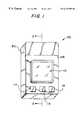
- FIG. 1is an perspective view of an exemplary embodiment of an occupancy sensor according to the present invention
- FIG. 2is a cross-sectional view of the occupancy sensor of FIG. 1 according to the present invention, taken from line 2 — 2 of FIG. 1;
- FIG. 3is a plan view of the field of view of the occupancy sensor of FIG. 1 according to the present invention.
- FIG. 4is a front elevational view of an exemplary embodiment of the flat lens of the occupancy sensor of FIG. 1 according to the present invention
- FIG. 5is a side elevational view of the sensing ranges provided by the flat lens of FIG. 4 according to the present invention.
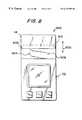
- FIG. 6is a front elevational view of the occupancy sensor of FIG. 1 indicating the positions of LED indicators according to the present invention
- FIG. 7is a cross-sectional view of the occupancy sensor of FIG. 6 indicating the positions of LED indicators according to the present invention, taken from line 7 — 7 of FIG. 6 .
- FIG. 8is a front elevational view of an exemplary embodiment of an access door of the occupancy sensor of FIG. 1 according to the present invention.
- FIG. 9is a circuit diagram of an exemplary embodiment of the sensor circuitry of the occupancy sensor of FIG. 1 according to the present invention.
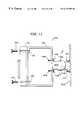
- FIG. 10is a circuit diagram of an exemplary embodiment of the override timer circuit of the sensor circuitry of FIG. 9 according to the present invention.
- FIG. 11is a side elevational view of an occupancy sensor system according to the present invention.
- the present inventionprovides occupancy sensors that more efficiently sense long-range occupancy within a narrow field of view.
- the present inventionis well-suited for environments with long aisles, high ceilings, and high intensity discharge lighting.
- FIGS. 1 and 2show an exemplary embodiment of occupancy sensor 100 constructed in accordance with the present invention.
- Occupancy sensor 100includes a rigid housing 102 , which is preferably fabricated in plastic, disposed about circuit board 104 .
- Circuit board 104has sensor circuitry 106 mounted thereon.
- Sensor circuitry 106includes sensing circuit 108 that generates a detecting beam, which is preferably an infrared detecting beam.
- sensing circuit 108can be passive, as described below with respect to the embodiment shown in FIG. 9 .
- Rigid housing 102has an open area 110 above sensing circuit 108 .
- Mounted on rigid housing 102 over open area 110is flat lens 112 .
- Flat lens 112is preferably a Fresnel lens.
- Flat lens 112provides more efficient longer range sensing within a narrower field of view than conventional curved lenses.
- Flat lens 112causes the parallel rays of the detecting beam generated from sensing circuit 108 to diverge less than if they had been passed through a conventional curved lens. This results in less beam distortion, increasing the sensitivity and range of occupancy sensor 100 .
- flat lens 112enables occupancy sensor 100 to provide more efficient sensing by focusing the detecting beam into a narrower longer range beam.
- sensing circuit 108is preferably positioned such that the detecting beam is substantially flat lens 112 .
- the area of flat lens 112can be substantially less than that of a curved lens. This advantageously reduces the cost of occupancy sensor 100 .
- Occupancy sensor 100optionally includes manual override switches 114 and 116 .
- switch 114sets sensor 100 in occupancy mode (i.e., sensor 100 outputs a signal indicating occupancy)
- switch 116sets sensor 100 in stand-by mode (i.e., sensor 100 outputs a signal indicating non-occupancy). If both switches are actuated, sensor 100 is preferably set in stand-by mode.
- Occupancy sensor 100preferably includes manual override timer switch 115 that when activated sets sensor 100 in occupancy mode for a predetermined time period. Substantially upon elapse of the predetermined time period, sensor 100 automatically returns to normal operation.
- Occupancy sensor 100also preferably includes access door 118 .
- Access door 118provides access to adjustment controls (described below with respect to FIGS. 8 and 9) and protects the controls and sensor circuitry 106 from dust and other airborne particles.
- FIG. 3shows detecting beam 302 of occupancy sensor 100 .
- Occupancy sensor 100is mounted preferably high on wall 303 .
- Detecting beam 302is directed down aisle 304 between storage areas 306 and 308 .
- Detecting beam 302has a maximum range 310 of preferably about 100 feet and a field of view 312 that can range from preferably about 15° to preferably about 25°.
- ranges less than maximum range 310can be provided by sensor 100 by positioning sensor 100 such that detecting beam 302 is directed at a point down aisle 304 between sensor 100 and maximum range 310 .
- FIG. 4shows an exemplary embodiment of flat lens 112 constructed in accordance with the present invention.
- Flat lens 112includes lens segments 402 , 404 , 406 , and 408 .
- Lens segment 402provides occupancy sensor 100 with long-range sensing.
- Lens segments 404 and 406provide sensor 100 with two intermediate ranges of sensing, and lens segment 408 provides sensor 100 with short-range sensing.
- the four ranges of occupancy sensing provided by lens segments 402 , 404 , 406 , and 408are within field of view 312 .
- other numbers of lens segments and lens segment geometries and configurationscan be provided, as is known in the art.
- FIG. 5shows the projection of detecting beams 502 , 504 , 506 , and 508 resulting respectively from lens segments 402 , 404 , 406 , and 408 of flat lens 112 of FIG. 4 .
- sensor circuitry 106includes light emitting diodes (LEDs) 602 and 604 , as shown in FIGS. 6 and 7.
- LEDs 602 and 604illuminate when occupancy is sensed.
- LED 602is preferably positioned on circuit board 104 such that it is centered under lens segment 404 at its upper border with lens segment 402 .
- Most of the light rays of LED 602parallel long-range detecting beam 502 of lens segment 402 .
- LED 602therefore appears to illuminate more brightly than LED 604 when viewed from within the long-range field of view.
- the location of the lower limit of the long-range field of viewcan be determined.
- the location of the upper limit of the long-range field of viewcan be determined. Positional adjustments of sensor 100 can then be made accordingly.
- LED 604is preferably positioned on circuit board 104 such that it is centered under lens segment 406 at its lower border with lens segment 408 . Most of the light rays of LED 604 parallel short-range detecting beam 508 of lens segment 408 . LED 604 therefore appears to illuminate more brightly than LED 602 when viewed from within the short-range field of view. Thus, by viewing from the designated area when LED 604 appears to illuminate more brightly than LED 602 , the location of the upper limit of the short-range field of view can be determined. By viewing from the designated area when LED 604 first illuminates, the location of the lower limit of the short-range field of view can be determined. Positional adjustments of sensor 100 can then be made accordingly.
- occupancy sensor 100can indicate when occupancy is sensed within the various sensing ranges of field of view 312 .
- sound transmitting devicesthat transmit different sound signals to a receiver can be used to indicate the upper and lower limits of the various ranges.
- FIG. 8shows an exemplary embodiment of access door 118 constructed in accordance with the present invention.
- Access door 118is preferably a sliding door that slides in the directions of arrow 802 .
- Access door 118permits access to adjustment controls 804 and 806 when open (as shown in FIG. 8) and protects adjustment controls 804 and 806 and sensor circuitry 106 from airborne particles when closed.
- Access door 118preferably remains attached to rigid housing 102 preferably with tabs 808 and 810 .
- Tabs 808 and 810slide along the inside edges of rigid housing 102 in preferably integrally molded tracks that stop tabs 808 and 810 when access door 118 is fully open.
- access door 118prevents the loss of access door 118 when sensor adjustments are being made, particularly when occupancy sensor 100 is located high on a wall or on a ceiling where retrieval of an accidentally dropped access door is unlikely.
- access door 118alternatively can be other types of doors, such as, for example, a hinged door that preferably remains in an open position while adjustments are being made.
- FIG. 9shows an exemplary embodiment of sensor circuitry 106 constructed in accordance with the present invention.
- Sensor circuitry 106includes sensing circuit 108 , which is preferably a passive infrared detecting circuit that preferably includes piezoelectric chip 902 . Detected changes in temperature are focused by flat lens 112 on chip 902 , which generates a small voltage in response. The small voltage is then processed through sensor circuitry 106 to generate an occupancy signal indicating occupancy.
- Sensor circuitry 106also includes input voltage terminal 906 for coupling to an input voltage, ground terminal 908 for coupling to ground or neutral, and output terminal 904 for providing occupancy signals to one or more electrical appliances, such as, for example, high intensity discharge (HID) lighting.
- Output terminal 904is preferably a relay contact whose output signal is determined by the position of switch 910 (e.g., open position indicates non occupancy, while closed position indicates occupancy). The position of switch 910 is controlled by relay coil 926 , which responds accordingly when sensor circuitry 106 goes from stand-by mode to occupancy mode and vice versa.
- sensor circuitry 106includes auxiliary output relay contacts 966 .
- Voltage regulation circuit 911provides two internal voltages.
- the first internal voltageis preferably about 6.8 volts set by Zener diode 912 at node 913
- the second internal voltageis preferably about 30 volts set by Zener diode 928 at node 927 .
- Sensor circuitry 106further includes NPN Darlington pairs 930 , 932 , 940 , 942 , 944 , and 954 ; NPN transistors 914 , 922 , 924 , 934 , 946 , 948 , 950 , 958 , and 960 ; PNP transistors 916 , 918 , 920 , 962 , and 964 ; manually actuated switches 114 , 115 , and 116 ; and LEDs 602 and 604 . All capacitors are preferably in the microfarad range.
- Sensor circuitry 106includes delay timer circuit 937 , which includes capacitor 936 and potentiometer 938 .
- capacitor 936charges up.
- sensor circuitry 106continues to output a signal indicating occupancy until capacitor 936 discharges through resistor 939 and potentiometer 938 .
- This delay timeprevents lighting or other electrical appliances from abruptly turning off when a person momentarily leaves the sensor's field of view.
- the time delaycan preferably be adjusted from about 15 seconds to about 30 minutes by varying potentiometer 938 via adjustment control 804 .
- Sensor circuitry 106preferably includes warm-up timer circuit 955 , which sets occupancy sensor 100 in occupancy mode for a predetermined warm-up period when power is first applied to sensor 100 .
- Sensor 100is thus well-suited for HID lighting, provided that both are coupled to the same input voltage source, because HID lamps require a warm-up period at high intensity when first powered-up.
- Warm-up timer circuit 955includes capacitor 952 and potentiometer 956 .
- node 913quickly rises to about 6.8 volts DC.
- Capacitor 952which is initially discharged, first acts like a short circuit, permitting Darlington pair 954 to turn ON. This provides an activating signal (i.e., a logical “1” signal) at node 957 , which causes sensor 100 to output a signal indicating occupancy regardless of whether occupancy is actually sensed. Until capacitor 952 charges up, sensor circuitry 106 continues to output a signal indicating occupancy.
- capacitor 952Once capacitor 952 is charged up, it acts like an open circuit, causing voltage at node 953 to go low, turning OFF Darlington pair 954 . This returns sensor circuitry 106 to normal operation. When sensor 100 powers-down, capacitor 952 discharges through NPN transistor 914 .
- the warm-up periodis thus substantially the charge-up time of capacitor 952 , which is determined by the values of capacitor 952 and potentiometer 956 . Accordingly, the warm-up time can be adjusted by varying potentiometer 956 via adjustment control 806 , and preferably ranges from about 15 to 30 minutes.
- Sensor circuitry 106preferably also includes override timer circuit 1000 .
- Override timer circuit 1000sets occupancy sensor 100 in occupancy mode for a predetermined time period when activated by switch 115 .
- the predetermined time periodcan be adjusted up to several hundred hours.
- Occupancy sensor 100is again well-suited for HID lighting, because HID lamps require a burn-in period of about 100 to 200 hours at high intensity when first installed.
- Override timer circuit 1000is coupled to node 913 to receive input voltage. The output of override timer circuit 1000 is coupled to node 957 . When activated by switch 115 , override timer circuit 1000 outputs a logical “1” signal causing sensor 100 to output a signal indicating occupancy regardless of whether occupancy is actually sensed. Override timer 1000 can be other known circuits that when activated output a logical “1” signal for an adjustable time period of up to several hundred hours.
- FIG. 10shows an exemplary embodiment of override timer circuit 1000 constructed in accordance with the present invention.
- Override timer circuit 1000includes timer chip 1002 , which can be an MC14536 programmable timer chip, manufactured by Motorola, Inc, of Austin, Tex. Pin connections for timer chip 1002 are as shown in FIG. 10 .
- Override timer circuit 1000also includes resistors 1004 and 1008 , capacitor 1006 , diode 1012 , and potentiometer 1010 . Potentiometer 1010 is preset such that the resultant oscillator frequency preferably is about 23.3 Hz. At that frequency, timer chip 1002 outputs a logical “1” signal for about 100 hours, after which the output signal goes low, returning occupancy sensor 100 to normal operation.
- FIG. 11shows an exemplary embodiment of occupancy sensor system 1100 constructed in accordance with the present invention.
- System 1100includes occupancy sensor 100 mounted to electrical enclosure 1102 with mounting screws 1104 through threaded holes 1105 .
- Electrical enclosure 1102fastens to electrical connector 1106 with mounting screws 1108 and threaded holes 1109 .
- any other suitable manner of fastening sensor 100 to enclosure 1102 and of fastening enclosure 1102 to connector 1106can be used.
- enclosure 1102 and connector 1106can be integrally constructed (e.g., stamped or welded) to form a single unit.
- the assembly of sensor 100 , enclosure 1102 , and connector 1106i.e., occupancy sensor system 1100
- structure 1110which may be a wall, ceiling, support beam, or any other structure capable of supporting system 1100 .
- system 1100can be mounted in any other suitable manner.
- Electrical connector 1106is preferably hollow to permit electrical wiring (not shown) to pass through from structure 1110 to electrical enclosure 1102 . Electrical connections to sensor 100 can accordingly be made in enclosure 1102 .
- connector 1106includes rotatable portion 1114 that rotates about fixed portion 1116 . This permits occupancy sensor 100 to be angled horizontally and vertically with respect to structure 1110 , thus permitting final sensing alignments of sensor 100 to be made.
- occupancy sensor system 1100can include occupancy sensor 100 fastened to any known swivel type bracket or other similar mounting hardware that permits sensor 100 to be angled horizontally and vertically with respect to structure 1110 .
Landscapes
- Physics & Mathematics (AREA)
- General Physics & Mathematics (AREA)
- Geophysics And Detection Of Objects (AREA)
- Circuit Arrangement For Electric Light Sources In General (AREA)
Abstract
Description
Claims (24)
Priority Applications (1)
| Application Number | Priority Date | Filing Date | Title |
|---|---|---|---|
| US09/212,738US6215398B1 (en) | 1997-12-18 | 1998-12-15 | Occupancy sensors for long-range sensing within a narrow field of view |
Applications Claiming Priority (2)
| Application Number | Priority Date | Filing Date | Title |
|---|---|---|---|
| US6801297P | 1997-12-18 | 1997-12-18 | |
| US09/212,738US6215398B1 (en) | 1997-12-18 | 1998-12-15 | Occupancy sensors for long-range sensing within a narrow field of view |
Publications (1)
| Publication Number | Publication Date |
|---|---|
| US6215398B1true US6215398B1 (en) | 2001-04-10 |
Family
ID=26748487
Family Applications (1)
| Application Number | Title | Priority Date | Filing Date |
|---|---|---|---|
| US09/212,738Expired - LifetimeUS6215398B1 (en) | 1997-12-18 | 1998-12-15 | Occupancy sensors for long-range sensing within a narrow field of view |
Country Status (1)
| Country | Link |
|---|---|
| US (1) | US6215398B1 (en) |
Cited By (32)
| Publication number | Priority date | Publication date | Assignee | Title |
|---|---|---|---|---|
| WO2003019067A1 (en)* | 2001-08-21 | 2003-03-06 | Scientific Technoligies Incorporated | Presence sensing system and method |
| USD472486S1 (en) | 2002-01-18 | 2003-04-01 | Leviton Manufacturing Co., Inc. | Occupancy sensor |
| USD472487S1 (en) | 2002-01-18 | 2003-04-01 | Leviton Manufacturing Co., Inc. | Mid-section cover for an occupancy sensor |
| US6850159B1 (en) | 2001-05-15 | 2005-02-01 | Brian P. Platner | Self-powered long-life occupancy sensors and sensor circuits |
| US20070182554A1 (en)* | 2006-02-06 | 2007-08-09 | Cooper Technologies Company | Infrared occupancy sensor |
| US20070182581A1 (en)* | 2006-02-06 | 2007-08-09 | Cooper Technologies Company | Acoustic occupancy sensor |
| US7333903B2 (en) | 2005-09-12 | 2008-02-19 | Acuity Brands, Inc. | Light management system having networked intelligent luminaire managers with enhanced diagnostics capabilities |
| US20080174429A1 (en)* | 2007-01-19 | 2008-07-24 | Jenesis International, Inc. | Motion sensor with LED aiming aid |
| US7411489B1 (en)* | 1999-12-29 | 2008-08-12 | Cooper Wiring Devices, Inc. | Self-adjusting dual technology occupancy sensor system and method |
| US20080273754A1 (en)* | 2007-05-04 | 2008-11-06 | Leviton Manufacturing Co., Inc. | Apparatus and method for defining an area of interest for image sensing |
| US20090026979A1 (en)* | 2007-07-25 | 2009-01-29 | Square D Company | Lighting load management system for lighting systems having multiple power circuits |
| USD587613S1 (en)* | 2008-07-01 | 2009-03-03 | Hubbell Incorporated | Occupancy sensor |
| US20090278479A1 (en)* | 2008-05-06 | 2009-11-12 | Platner Brian P | Networked, wireless lighting control system with distributed intelligence |
| US20100097226A1 (en)* | 2008-10-22 | 2010-04-22 | Leviton Manufacturing Co., Inc. | Occupancy sensing with image and supplemental sensing |
| US7817063B2 (en) | 2005-10-05 | 2010-10-19 | Abl Ip Holding Llc | Method and system for remotely monitoring and controlling field devices with a street lamp elevated mesh network |
| US20100294915A1 (en)* | 2009-05-21 | 2010-11-25 | Williams Jonathan D | Occupancy sensor and override unit for photosensor-based control of load |
| US20110025497A1 (en)* | 2008-08-15 | 2011-02-03 | Zaveruha Ryan A | Occupancy sensors programmed to determine loss of lamp life as lamp is used |
| US20110155911A1 (en)* | 2006-10-13 | 2011-06-30 | Claytor Richard N | Passive infrared detector |
| USD654442S1 (en)* | 2010-10-14 | 2012-02-21 | Samsung Electronics Co., Ltd. | Exterior sensor of illumination intensity for a display unit of outdoor advertisement |
| US8140276B2 (en) | 2008-02-27 | 2012-03-20 | Abl Ip Holding Llc | System and method for streetlight monitoring diagnostics |
| US20150260387A1 (en)* | 2014-03-13 | 2015-09-17 | Bruce Gamble | Night lighting system, method and component kit |
| US10378745B2 (en) | 2017-05-03 | 2019-08-13 | Hubbell Incorporated | Wall mount light fixture with external sensor housing |
| US20200119942A1 (en)* | 2018-10-10 | 2020-04-16 | Honeywell International Inc. | Wireless occupancy sensor with controllable light indicator |
| US10816230B2 (en) | 2018-10-10 | 2020-10-27 | Ademco Inc. | Temperature sensing strategy with multiple temperature sensors |
| US10859281B2 (en) | 2018-10-10 | 2020-12-08 | Ademco Inc. | Thermostat assembly with removable trim ring |
| US10895397B2 (en) | 2018-10-10 | 2021-01-19 | Ademco Inc. | Wire detection for an HVAC controller |
| US10907854B2 (en) | 2018-10-10 | 2021-02-02 | Ademco Inc. | Automatic changeover mode in an HVAC controller with reversible deadband enforcement |
| US10908001B2 (en) | 2018-10-10 | 2021-02-02 | Ademco Inc. | Wireless sensor with mounting plate |
| US10907852B2 (en) | 2018-10-10 | 2021-02-02 | Ademco Inc. | Remote sensor with improved occupancy sensing |
| US11067307B2 (en) | 2018-10-10 | 2021-07-20 | Ademco Inc. | Thermostat user interface with smart menu structure |
| US11236923B2 (en) | 2018-10-10 | 2022-02-01 | Ademco Inc. | Thermostat with sensor priority screen |
| USD1038775S1 (en)* | 2024-02-06 | 2024-08-13 | Signcomplex Limited | Occupancy sensor |
Citations (43)
| Publication number | Priority date | Publication date | Assignee | Title |
|---|---|---|---|---|
| US3699382A (en)* | 1971-02-04 | 1972-10-17 | Sylvania Electric Prod | Auxiliary lighting system for arc lamp |
| US3936822A (en) | 1974-06-14 | 1976-02-03 | Hirschberg Kenneth A | Method and apparatus for detecting weapon fire |
| US4060123A (en) | 1976-09-27 | 1977-11-29 | Fabri-Tek Incorporated | Energy saving temperature control apparatus |
| US4169982A (en) | 1977-12-08 | 1979-10-02 | Rittmann Albert D | Touch-actuated electronic switch |
| US4223831A (en) | 1979-02-21 | 1980-09-23 | Szarka Jay R | Sound activated temperature control system |
| US4321594A (en)* | 1979-11-01 | 1982-03-23 | American District Telegraph Company | Passive infrared detector |
| US4340826A (en) | 1981-05-07 | 1982-07-20 | Harvey Hubbell Incorporated | Low current pilot light and switch |
| US4346427A (en) | 1979-06-29 | 1982-08-24 | Robert Rothenhaus | Control device responsive to infrared radiation |
| US4365167A (en) | 1980-06-25 | 1982-12-21 | Centra-Burkle Gmbh & Co. | Switchover system for binary load control |
| US4451734A (en)* | 1982-05-17 | 1984-05-29 | Cerberus Ag | Infrared intrusion sensor with selectable radiation patterns |
| US4527216A (en) | 1983-03-16 | 1985-07-02 | International Business Machines Corporation | Sub-milliamp mechanical relay control |
| US4618770A (en) | 1985-03-21 | 1986-10-21 | Rca Corporation | Electrical controller having a window discriminator |
| US4630684A (en) | 1984-06-18 | 1986-12-23 | Santa Barbara Research Center | Fire sensing and suppression method and system responsive to optical radiation and mechanical wave energy |
| US4703171A (en) | 1985-11-05 | 1987-10-27 | Target Concepts Inc. | Lighting control system with infrared occupancy detector |
| US4746906A (en) | 1986-06-30 | 1988-05-24 | Detection Systems, Inc. | Dual technology intruder detection system with modular optics |
| US4772875A (en) | 1986-05-16 | 1988-09-20 | Denning Mobile Robotics, Inc. | Intrusion detection system |
| US4825079A (en) | 1986-05-30 | 1989-04-25 | Sumitomo Metal Company Limited | Pyroelectric infrared detector |
| US4864278A (en)* | 1987-02-06 | 1989-09-05 | Robert Hooke Memorial Laboratories, Inc. | Optical intrusion detection system and method |
| US4868391A (en)* | 1987-07-27 | 1989-09-19 | U.S. Philips Corp. | Infrared lens arrays |
| US4874962A (en) | 1987-05-21 | 1989-10-17 | Hermans Albert L | Low power, leakage current switching circuit |
| US4890093A (en) | 1988-10-27 | 1989-12-26 | Schlage Lock Company | Solar powered proximity triggered light |
| US4975584A (en) | 1989-03-29 | 1990-12-04 | Mountain Ocean, Ltd. | Method and apparatus for collecting, processing and displaying ultraviolet radiation data |
| US5015994A (en) | 1989-12-28 | 1991-05-14 | Grh Electronics | Security light controlled by motion detector |
| US5023593A (en) | 1990-08-20 | 1991-06-11 | Brox Steven E | Passive infrared/acoustic pool security system |
| US5128654A (en) | 1990-02-23 | 1992-07-07 | Lightolier Incorporated | Preset light controller including infrared sensor operable in multiple modes |
| US5142199A (en) | 1990-11-29 | 1992-08-25 | Novitas, Inc. | Energy efficient infrared light switch and method of making same |
| US5151840A (en) | 1990-09-11 | 1992-09-29 | Raj Industries, Inc. | Switch protection circuit |
| US5153560A (en) | 1990-09-07 | 1992-10-06 | Sumitomo Metal Mining Company, Limited | Apparatus for detecting presence of person inside room having door |
| US5155474A (en)* | 1991-06-28 | 1992-10-13 | Park Photo Protection System Ltd. | Photographic security system |
| US5189393A (en) | 1991-06-07 | 1993-02-23 | The Watt Stopper Inc. | Dual technology motion sensor |
| US5266807A (en) | 1986-10-10 | 1993-11-30 | Leviton Manufacturing Co., Inc. | Passive infrared detection system |
| US5276427A (en) | 1991-07-08 | 1994-01-04 | Digital Security Controls Ltd. | Auto-adjust motion detection system |
| US5307051A (en) | 1991-09-24 | 1994-04-26 | Sedlmayr Steven R | Night light apparatus and method for altering the environment of a room |
| US5311024A (en)* | 1992-03-11 | 1994-05-10 | Sentrol, Inc. | Lens arrangement for intrusion detection device |
| US5381323A (en)* | 1993-10-01 | 1995-01-10 | Regent Lighting Corporation | Sensor housing and adjustable mast arm for a swivel lighting fixture |
| US5386210A (en) | 1991-08-28 | 1995-01-31 | Intelectron Products Company | Method and apparatus for detecting entry |
| US5406073A (en)* | 1993-01-25 | 1995-04-11 | Phoenix Controls Corporation | System for detecting a movable entity within a selected space |
| US5424717A (en)* | 1991-06-21 | 1995-06-13 | Memco Limited | Laser light transmitter and proximity detector |
| US5428345A (en) | 1994-03-30 | 1995-06-27 | Sentrol, Inc. | Method of and apparatus for operating a security system to produce an alarm signal |
| US5442532A (en)* | 1993-07-30 | 1995-08-15 | Pace Control Technologies, Inc. | Decorative lighting fixture for motion detection |
| US5534850A (en) | 1994-07-07 | 1996-07-09 | Larry C. Y. Lee | Transient control circuit for occupancy detector |
| US5662411A (en)* | 1995-03-20 | 1997-09-02 | Regent Lighting Corporation | Motion activated light fixture with fixed sensor |
| US5701117A (en) | 1996-01-18 | 1997-12-23 | Brian Page Platner | Occupancy detector |
- 1998
- 1998-12-15USUS09/212,738patent/US6215398B1/ennot_activeExpired - Lifetime
Patent Citations (45)
| Publication number | Priority date | Publication date | Assignee | Title |
|---|---|---|---|---|
| US3699382A (en)* | 1971-02-04 | 1972-10-17 | Sylvania Electric Prod | Auxiliary lighting system for arc lamp |
| US3936822A (en) | 1974-06-14 | 1976-02-03 | Hirschberg Kenneth A | Method and apparatus for detecting weapon fire |
| US4060123A (en) | 1976-09-27 | 1977-11-29 | Fabri-Tek Incorporated | Energy saving temperature control apparatus |
| US4169982A (en) | 1977-12-08 | 1979-10-02 | Rittmann Albert D | Touch-actuated electronic switch |
| US4223831A (en) | 1979-02-21 | 1980-09-23 | Szarka Jay R | Sound activated temperature control system |
| US4346427B1 (en) | 1979-06-29 | 1987-12-08 | ||
| US4346427A (en) | 1979-06-29 | 1982-08-24 | Robert Rothenhaus | Control device responsive to infrared radiation |
| US4321594A (en)* | 1979-11-01 | 1982-03-23 | American District Telegraph Company | Passive infrared detector |
| US4365167A (en) | 1980-06-25 | 1982-12-21 | Centra-Burkle Gmbh & Co. | Switchover system for binary load control |
| US4340826A (en) | 1981-05-07 | 1982-07-20 | Harvey Hubbell Incorporated | Low current pilot light and switch |
| US4451734A (en)* | 1982-05-17 | 1984-05-29 | Cerberus Ag | Infrared intrusion sensor with selectable radiation patterns |
| US4527216A (en) | 1983-03-16 | 1985-07-02 | International Business Machines Corporation | Sub-milliamp mechanical relay control |
| US4630684A (en) | 1984-06-18 | 1986-12-23 | Santa Barbara Research Center | Fire sensing and suppression method and system responsive to optical radiation and mechanical wave energy |
| US4618770A (en) | 1985-03-21 | 1986-10-21 | Rca Corporation | Electrical controller having a window discriminator |
| US4703171A (en) | 1985-11-05 | 1987-10-27 | Target Concepts Inc. | Lighting control system with infrared occupancy detector |
| US4772875A (en) | 1986-05-16 | 1988-09-20 | Denning Mobile Robotics, Inc. | Intrusion detection system |
| US4825079A (en) | 1986-05-30 | 1989-04-25 | Sumitomo Metal Company Limited | Pyroelectric infrared detector |
| US4746906A (en) | 1986-06-30 | 1988-05-24 | Detection Systems, Inc. | Dual technology intruder detection system with modular optics |
| US5266807A (en) | 1986-10-10 | 1993-11-30 | Leviton Manufacturing Co., Inc. | Passive infrared detection system |
| US4864278A (en)* | 1987-02-06 | 1989-09-05 | Robert Hooke Memorial Laboratories, Inc. | Optical intrusion detection system and method |
| US4874962A (en) | 1987-05-21 | 1989-10-17 | Hermans Albert L | Low power, leakage current switching circuit |
| US4874962B1 (en) | 1987-05-21 | 1995-04-04 | Albert L Hermans | Low power, leakage current switching circuit |
| US4868391A (en)* | 1987-07-27 | 1989-09-19 | U.S. Philips Corp. | Infrared lens arrays |
| US4890093A (en) | 1988-10-27 | 1989-12-26 | Schlage Lock Company | Solar powered proximity triggered light |
| US4975584A (en) | 1989-03-29 | 1990-12-04 | Mountain Ocean, Ltd. | Method and apparatus for collecting, processing and displaying ultraviolet radiation data |
| US5015994A (en) | 1989-12-28 | 1991-05-14 | Grh Electronics | Security light controlled by motion detector |
| US5128654A (en) | 1990-02-23 | 1992-07-07 | Lightolier Incorporated | Preset light controller including infrared sensor operable in multiple modes |
| US5023593A (en) | 1990-08-20 | 1991-06-11 | Brox Steven E | Passive infrared/acoustic pool security system |
| US5153560A (en) | 1990-09-07 | 1992-10-06 | Sumitomo Metal Mining Company, Limited | Apparatus for detecting presence of person inside room having door |
| US5151840A (en) | 1990-09-11 | 1992-09-29 | Raj Industries, Inc. | Switch protection circuit |
| US5142199A (en) | 1990-11-29 | 1992-08-25 | Novitas, Inc. | Energy efficient infrared light switch and method of making same |
| US5189393A (en) | 1991-06-07 | 1993-02-23 | The Watt Stopper Inc. | Dual technology motion sensor |
| US5424717A (en)* | 1991-06-21 | 1995-06-13 | Memco Limited | Laser light transmitter and proximity detector |
| US5155474A (en)* | 1991-06-28 | 1992-10-13 | Park Photo Protection System Ltd. | Photographic security system |
| US5276427A (en) | 1991-07-08 | 1994-01-04 | Digital Security Controls Ltd. | Auto-adjust motion detection system |
| US5386210A (en) | 1991-08-28 | 1995-01-31 | Intelectron Products Company | Method and apparatus for detecting entry |
| US5307051A (en) | 1991-09-24 | 1994-04-26 | Sedlmayr Steven R | Night light apparatus and method for altering the environment of a room |
| US5311024A (en)* | 1992-03-11 | 1994-05-10 | Sentrol, Inc. | Lens arrangement for intrusion detection device |
| US5406073A (en)* | 1993-01-25 | 1995-04-11 | Phoenix Controls Corporation | System for detecting a movable entity within a selected space |
| US5442532A (en)* | 1993-07-30 | 1995-08-15 | Pace Control Technologies, Inc. | Decorative lighting fixture for motion detection |
| US5381323A (en)* | 1993-10-01 | 1995-01-10 | Regent Lighting Corporation | Sensor housing and adjustable mast arm for a swivel lighting fixture |
| US5428345A (en) | 1994-03-30 | 1995-06-27 | Sentrol, Inc. | Method of and apparatus for operating a security system to produce an alarm signal |
| US5534850A (en) | 1994-07-07 | 1996-07-09 | Larry C. Y. Lee | Transient control circuit for occupancy detector |
| US5662411A (en)* | 1995-03-20 | 1997-09-02 | Regent Lighting Corporation | Motion activated light fixture with fixed sensor |
| US5701117A (en) | 1996-01-18 | 1997-12-23 | Brian Page Platner | Occupancy detector |
Non-Patent Citations (2)
| Title |
|---|
| "CX-100 Passive Infrared Sensor" (data sheet), Publication No. 6301, published by The Watt Stopper(R), Inc., of Santa Clara, California (undated). |
| "CX-100 Passive Infrared Sensor" (data sheet), Publication No. 6301, published by The Watt Stopper®, Inc., of Santa Clara, California (undated). |
Cited By (68)
| Publication number | Priority date | Publication date | Assignee | Title |
|---|---|---|---|---|
| US7411489B1 (en)* | 1999-12-29 | 2008-08-12 | Cooper Wiring Devices, Inc. | Self-adjusting dual technology occupancy sensor system and method |
| US6753776B2 (en) | 2000-08-25 | 2004-06-22 | Scientific Technologies Incorporated | Presence sensing system and method |
| US6850159B1 (en) | 2001-05-15 | 2005-02-01 | Brian P. Platner | Self-powered long-life occupancy sensors and sensor circuits |
| US7576647B1 (en) | 2001-05-15 | 2009-08-18 | Abl Ip Holding, Llc | Self-powered long-life occupancy sensors and sensor circuits |
| US7319389B1 (en) | 2001-05-15 | 2008-01-15 | Brian P. Platner | Self-powered long-life occupancy sensors and sensor circuits |
| US7586408B1 (en) | 2001-05-15 | 2009-09-08 | Abl Ip Holding, Llc | Self-powered long-life occupancy sensors and sensor circuits |
| WO2003019067A1 (en)* | 2001-08-21 | 2003-03-06 | Scientific Technoligies Incorporated | Presence sensing system and method |
| USD472486S1 (en) | 2002-01-18 | 2003-04-01 | Leviton Manufacturing Co., Inc. | Occupancy sensor |
| USD472487S1 (en) | 2002-01-18 | 2003-04-01 | Leviton Manufacturing Co., Inc. | Mid-section cover for an occupancy sensor |
| US8010319B2 (en) | 2005-09-12 | 2011-08-30 | Abl Ip Holding Llc | Light management system having networked intelligent luminaire managers |
| US7546168B2 (en) | 2005-09-12 | 2009-06-09 | Abl Ip Holding Llc | Owner/operator control of a light management system using networked intelligent luminaire managers |
| US20080147337A1 (en)* | 2005-09-12 | 2008-06-19 | Acuity Brands, Inc. | Light Management System Having Networked Intelligent Luminaire Managers with Enhanced Diagnostics Capabilities |
| US7333903B2 (en) | 2005-09-12 | 2008-02-19 | Acuity Brands, Inc. | Light management system having networked intelligent luminaire managers with enhanced diagnostics capabilities |
| US7911359B2 (en) | 2005-09-12 | 2011-03-22 | Abl Ip Holding Llc | Light management system having networked intelligent luminaire managers that support third-party applications |
| US8260575B2 (en) | 2005-09-12 | 2012-09-04 | Abl Ip Holding Llc | Light management system having networked intelligent luminaire managers |
| US7603184B2 (en) | 2005-09-12 | 2009-10-13 | Abl Ip Holding Llc | Light management system having networked intelligent luminaire managers |
| US7529594B2 (en) | 2005-09-12 | 2009-05-05 | Abl Ip Holding Llc | Activation device for an intelligent luminaire manager |
| US7761260B2 (en) | 2005-09-12 | 2010-07-20 | Abl Ip Holding Llc | Light management system having networked intelligent luminaire managers with enhanced diagnostics capabilities |
| US7546167B2 (en) | 2005-09-12 | 2009-06-09 | Abl Ip Holdings Llc | Network operation center for a light management system having networked intelligent luminaire managers |
| US7817063B2 (en) | 2005-10-05 | 2010-10-19 | Abl Ip Holding Llc | Method and system for remotely monitoring and controlling field devices with a street lamp elevated mesh network |
| US7777632B2 (en) | 2006-02-06 | 2010-08-17 | Cooper Technologies Company | Acoustic occupancy sensor |
| US7541924B2 (en) | 2006-02-06 | 2009-06-02 | Cooper Technologies Company | Infrared occupancy sensor |
| US20070182581A1 (en)* | 2006-02-06 | 2007-08-09 | Cooper Technologies Company | Acoustic occupancy sensor |
| US20070182554A1 (en)* | 2006-02-06 | 2007-08-09 | Cooper Technologies Company | Infrared occupancy sensor |
| US9885608B2 (en) | 2006-10-13 | 2018-02-06 | Fresnel Technologies, Inc. | Passive infrared detector |
| US20110155911A1 (en)* | 2006-10-13 | 2011-06-30 | Claytor Richard N | Passive infrared detector |
| US9116037B2 (en) | 2006-10-13 | 2015-08-25 | Fresnel Technologies, Inc. | Passive infrared detector |
| US20090114800A1 (en)* | 2007-01-19 | 2009-05-07 | Jensen Bradford B | Motion sensor with led alignment aid |
| US7741597B2 (en) | 2007-01-19 | 2010-06-22 | Jenesis International Inc. | Motion sensor with LED alignment aid |
| US7459672B2 (en) | 2007-01-19 | 2008-12-02 | Jenesis International, Inc. | Motion sensor with LED aiming aid |
| WO2008091528A3 (en)* | 2007-01-19 | 2008-09-18 | Jenesis International Inc | Motion sensor with led alignment aid |
| US20080174429A1 (en)* | 2007-01-19 | 2008-07-24 | Jenesis International, Inc. | Motion sensor with LED aiming aid |
| US20080273754A1 (en)* | 2007-05-04 | 2008-11-06 | Leviton Manufacturing Co., Inc. | Apparatus and method for defining an area of interest for image sensing |
| US7688005B2 (en) | 2007-07-25 | 2010-03-30 | Square D Company | Lighting load management system for lighting systems having multiple power circuits |
| US20090026979A1 (en)* | 2007-07-25 | 2009-01-29 | Square D Company | Lighting load management system for lighting systems having multiple power circuits |
| US8594976B2 (en) | 2008-02-27 | 2013-11-26 | Abl Ip Holding Llc | System and method for streetlight monitoring diagnostics |
| US8140276B2 (en) | 2008-02-27 | 2012-03-20 | Abl Ip Holding Llc | System and method for streetlight monitoring diagnostics |
| US8442785B2 (en) | 2008-02-27 | 2013-05-14 | Abl Ip Holding Llc | System and method for streetlight monitoring diagnostics |
| US9215784B2 (en) | 2008-05-06 | 2015-12-15 | Abl Ip Holding, Llc | Networked, wireless lighting control system with distributed intelligence |
| WO2009137041A1 (en)* | 2008-05-06 | 2009-11-12 | Abl Ip Holding, Llc | Networked, wireless lighting control system with distributed intelligence |
| US10172213B2 (en) | 2008-05-06 | 2019-01-01 | Abl Ip Holding, Llc | Networked, wireless lighting control system with distributed intelligence |
| US20090278479A1 (en)* | 2008-05-06 | 2009-11-12 | Platner Brian P | Networked, wireless lighting control system with distributed intelligence |
| US8731689B2 (en) | 2008-05-06 | 2014-05-20 | Abl Ip Holding, Llc | Networked, wireless lighting control system with distributed intelligence |
| USD587613S1 (en)* | 2008-07-01 | 2009-03-03 | Hubbell Incorporated | Occupancy sensor |
| US8111131B2 (en) | 2008-08-15 | 2012-02-07 | Abl Ip Holding, Llc | Occupancy sensors programmed to determine loss of lamp life as lamp is used |
| US8237540B2 (en) | 2008-08-15 | 2012-08-07 | Abl Ip Holding, Llc | Occupancy sensors programmed to determine loss of lamp life as lamp is used |
| US20110025497A1 (en)* | 2008-08-15 | 2011-02-03 | Zaveruha Ryan A | Occupancy sensors programmed to determine loss of lamp life as lamp is used |
| US8410896B2 (en) | 2008-08-15 | 2013-04-02 | Abl Ip Holding, Llc | Occupancy sensors programmed to determine loss of lamp life as lamp is used |
| US20100097226A1 (en)* | 2008-10-22 | 2010-04-22 | Leviton Manufacturing Co., Inc. | Occupancy sensing with image and supplemental sensing |
| US8461510B2 (en) | 2009-05-21 | 2013-06-11 | Hubbell Incorporated | Occupancy sensor and ambient light control |
| US8796610B2 (en) | 2009-05-21 | 2014-08-05 | Hubbell Incorporated | Electric load control system including remote override function |
| US20100294915A1 (en)* | 2009-05-21 | 2010-11-25 | Williams Jonathan D | Occupancy sensor and override unit for photosensor-based control of load |
| US8143567B2 (en) | 2009-05-21 | 2012-03-27 | Hubbell Incorporated | Ambient light control system |
| USD654442S1 (en)* | 2010-10-14 | 2012-02-21 | Samsung Electronics Co., Ltd. | Exterior sensor of illumination intensity for a display unit of outdoor advertisement |
| US20150260387A1 (en)* | 2014-03-13 | 2015-09-17 | Bruce Gamble | Night lighting system, method and component kit |
| US10378745B2 (en) | 2017-05-03 | 2019-08-13 | Hubbell Incorporated | Wall mount light fixture with external sensor housing |
| US10859281B2 (en) | 2018-10-10 | 2020-12-08 | Ademco Inc. | Thermostat assembly with removable trim ring |
| US10816230B2 (en) | 2018-10-10 | 2020-10-27 | Ademco Inc. | Temperature sensing strategy with multiple temperature sensors |
| US20200119942A1 (en)* | 2018-10-10 | 2020-04-16 | Honeywell International Inc. | Wireless occupancy sensor with controllable light indicator |
| US10895397B2 (en) | 2018-10-10 | 2021-01-19 | Ademco Inc. | Wire detection for an HVAC controller |
| US10907854B2 (en) | 2018-10-10 | 2021-02-02 | Ademco Inc. | Automatic changeover mode in an HVAC controller with reversible deadband enforcement |
| US10908001B2 (en) | 2018-10-10 | 2021-02-02 | Ademco Inc. | Wireless sensor with mounting plate |
| US10907852B2 (en) | 2018-10-10 | 2021-02-02 | Ademco Inc. | Remote sensor with improved occupancy sensing |
| US11067307B2 (en) | 2018-10-10 | 2021-07-20 | Ademco Inc. | Thermostat user interface with smart menu structure |
| US11095469B2 (en)* | 2018-10-10 | 2021-08-17 | Ademco Inc. | Wireless occupancy sensor with controllable light indicator |
| US11236923B2 (en) | 2018-10-10 | 2022-02-01 | Ademco Inc. | Thermostat with sensor priority screen |
| US11708991B2 (en) | 2018-10-10 | 2023-07-25 | Ademco Inc. | Automatic changeover mode in an HVAC controller with reversible deadband enforcement |
| USD1038775S1 (en)* | 2024-02-06 | 2024-08-13 | Signcomplex Limited | Occupancy sensor |
Similar Documents
| Publication | Publication Date | Title |
|---|---|---|
| US6215398B1 (en) | Occupancy sensors for long-range sensing within a narrow field of view | |
| US4433328A (en) | Motion sensing energy controller | |
| US4703171A (en) | Lighting control system with infrared occupancy detector | |
| US7800049B2 (en) | Adjustable low voltage occupancy sensor | |
| US5128654A (en) | Preset light controller including infrared sensor operable in multiple modes | |
| US5673022A (en) | Motion sensor/photoelectric light sensor plug-in receptacle | |
| US5701117A (en) | Occupancy detector | |
| US4255746A (en) | Emergency lighting and fire detector system | |
| US9018841B2 (en) | Electrical wiring device | |
| US6798341B1 (en) | Network based multiple sensor and control device with temperature sensing and control | |
| US5266807A (en) | Passive infrared detection system | |
| US8232909B2 (en) | Doppler radar motion detector for an outdoor light fixture | |
| US7994928B2 (en) | Multifunction smoke alarm unit | |
| US20030065472A1 (en) | Local network based multiple sensor device with electrical load control means and with temperature sensor and heat detector that is exposed to ambient air by diffusion | |
| US6948831B1 (en) | Recessed light assembly adapted for use with motion detector | |
| US20100097226A1 (en) | Occupancy sensing with image and supplemental sensing | |
| US20070177384A1 (en) | Motion sensing lighting fixture | |
| US4408308A (en) | Sound actuated light switch | |
| WO1998001699A1 (en) | Outdoor solar lamp | |
| US8130099B2 (en) | Sensor light | |
| CA2619630C (en) | Multiple sensor lighting system | |
| US4380721A (en) | Proximity switch | |
| US4680576A (en) | Photoelectric smoke detector and alarm system | |
| EP0799461A1 (en) | Infrared motion detector with 180-degree detecting range | |
| US5733038A (en) | Protective device for a stand lamp |
Legal Events
| Date | Code | Title | Description |
|---|---|---|---|
| AS | Assignment | Owner name:PLATNER, BRIAN P., CONNECTICUT Free format text:ASSIGNMENT OF ASSIGNORS INTEREST;ASSIGNORS:MUDGE, PHILIP H.;FASSBENDER, WILLIAM J.;PLATNER, KEITH K.;REEL/FRAME:009759/0268 Effective date:19990125 | |
| STCF | Information on status: patent grant | Free format text:PATENTED CASE | |
| FPAY | Fee payment | Year of fee payment:4 | |
| FEPP | Fee payment procedure | Free format text:PAYOR NUMBER ASSIGNED (ORIGINAL EVENT CODE: ASPN); ENTITY STATUS OF PATENT OWNER: SMALL ENTITY | |
| FPAY | Fee payment | Year of fee payment:8 | |
| AS | Assignment | Owner name:ABL IP HOLDING, LLC, GEORGIA Free format text:ASSIGNMENT OF ASSIGNORS INTEREST;ASSIGNOR:PLATNER, BRIAN;REEL/FRAME:023065/0170 Effective date:20090420 | |
| FEPP | Fee payment procedure | Free format text:PAYER NUMBER DE-ASSIGNED (ORIGINAL EVENT CODE: RMPN); ENTITY STATUS OF PATENT OWNER: SMALL ENTITY Free format text:PAYOR NUMBER ASSIGNED (ORIGINAL EVENT CODE: ASPN); ENTITY STATUS OF PATENT OWNER: SMALL ENTITY | |
| FPAY | Fee payment | Year of fee payment:12 |