US6214629B1 - Analytical test device and method for use in medical diagnoses - Google Patents
Analytical test device and method for use in medical diagnosesDownload PDFInfo
- Publication number
- US6214629B1 US6214629B1US09/353,190US35319099AUS6214629B1US 6214629 B1US6214629 B1US 6214629B1US 35319099 AUS35319099 AUS 35319099AUS 6214629 B1US6214629 B1US 6214629B1
- Authority
- US
- United States
- Prior art keywords
- sample
- channel
- analyte
- determining
- troponin
- Prior art date
- Legal status (The legal status is an assumption and is not a legal conclusion. Google has not performed a legal analysis and makes no representation as to the accuracy of the status listed.)
- Expired - Lifetime
Links
Images


Classifications
- G—PHYSICS
- G01—MEASURING; TESTING
- G01N—INVESTIGATING OR ANALYSING MATERIALS BY DETERMINING THEIR CHEMICAL OR PHYSICAL PROPERTIES
- G01N33/00—Investigating or analysing materials by specific methods not covered by groups G01N1/00 - G01N31/00
- G01N33/48—Biological material, e.g. blood, urine; Haemocytometers
- G01N33/50—Chemical analysis of biological material, e.g. blood, urine; Testing involving biospecific ligand binding methods; Immunological testing
- G01N33/53—Immunoassay; Biospecific binding assay; Materials therefor
- G01N33/543—Immunoassay; Biospecific binding assay; Materials therefor with an insoluble carrier for immobilising immunochemicals
- G01N33/54366—Apparatus specially adapted for solid-phase testing
- G01N33/54386—Analytical elements
- G01N33/54387—Immunochromatographic test strips
- G—PHYSICS
- G01—MEASURING; TESTING
- G01N—INVESTIGATING OR ANALYSING MATERIALS BY DETERMINING THEIR CHEMICAL OR PHYSICAL PROPERTIES
- G01N2333/00—Assays involving biological materials from specific organisms or of a specific nature
- G01N2333/435—Assays involving biological materials from specific organisms or of a specific nature from animals; from humans
- G01N2333/46—Assays involving biological materials from specific organisms or of a specific nature from animals; from humans from vertebrates
- G01N2333/47—Assays involving proteins of known structure or function as defined in the subgroups
- G01N2333/4701—Details
- G01N2333/4712—Muscle proteins, e.g. myosin, actin, protein
- G—PHYSICS
- G01—MEASURING; TESTING
- G01N—INVESTIGATING OR ANALYSING MATERIALS BY DETERMINING THEIR CHEMICAL OR PHYSICAL PROPERTIES
- G01N2333/00—Assays involving biological materials from specific organisms or of a specific nature
- G01N2333/795—Porphyrin- or corrin-ring-containing peptides
- G01N2333/805—Haemoglobins; Myoglobins
- G—PHYSICS
- G01—MEASURING; TESTING
- G01N—INVESTIGATING OR ANALYSING MATERIALS BY DETERMINING THEIR CHEMICAL OR PHYSICAL PROPERTIES
- G01N2333/00—Assays involving biological materials from specific organisms or of a specific nature
- G01N2333/90—Enzymes; Proenzymes
- G01N2333/91—Transferases (2.)
- G01N2333/912—Transferases (2.) transferring phosphorus containing groups, e.g. kinases (2.7)
- G01N2333/91205—Phosphotransferases in general
- G01N2333/9123—Phosphotransferases in general with a nitrogenous group as acceptor (2.7.3), e.g. histidine kinases
- Y—GENERAL TAGGING OF NEW TECHNOLOGICAL DEVELOPMENTS; GENERAL TAGGING OF CROSS-SECTIONAL TECHNOLOGIES SPANNING OVER SEVERAL SECTIONS OF THE IPC; TECHNICAL SUBJECTS COVERED BY FORMER USPC CROSS-REFERENCE ART COLLECTIONS [XRACs] AND DIGESTS
- Y10—TECHNICAL SUBJECTS COVERED BY FORMER USPC
- Y10S—TECHNICAL SUBJECTS COVERED BY FORMER USPC CROSS-REFERENCE ART COLLECTIONS [XRACs] AND DIGESTS
- Y10S436/00—Chemistry: analytical and immunological testing
- Y10S436/811—Test for named disease, body condition or organ function
- Y—GENERAL TAGGING OF NEW TECHNOLOGICAL DEVELOPMENTS; GENERAL TAGGING OF CROSS-SECTIONAL TECHNOLOGIES SPANNING OVER SEVERAL SECTIONS OF THE IPC; TECHNICAL SUBJECTS COVERED BY FORMER USPC CROSS-REFERENCE ART COLLECTIONS [XRACs] AND DIGESTS
- Y10—TECHNICAL SUBJECTS COVERED BY FORMER USPC
- Y10S—TECHNICAL SUBJECTS COVERED BY FORMER USPC CROSS-REFERENCE ART COLLECTIONS [XRACs] AND DIGESTS
- Y10S436/00—Chemistry: analytical and immunological testing
- Y10S436/815—Test for named compound or class of compounds
Definitions
- This inventionrelates to analytical test devices and methods useful for analytical assays to determine the presence of analytes in fluid samples. It is especially useful for determining the presence of cardiac analytes in whole blood, although it is not so limited.
- the product and procedures of this inventioncan be utilized for many diagnostic purposes as well as for following the course of mammalian diseases and therapeutic treatments. It is applicable to many mammalian body fluids such as whole blood, serum, plasma and urine. Although this invention will be principally discussed as applied to detecting cardiac analytes it may also be applicable to other fields where antigen/antibody or equivalent reactions are utilized. Many related assay procedures especially those including immunoassays may be performed using the device of the present invention and its disclosed modifications. For example, immunoassays or non-immunoassay test formats employing separation of red blood cells from plasma and a lateral fluid path may be employed.
- Analytessuch as hormones for determining pregnancy or ovulation; viral, bacterial and fungal infectious microorganisms including H. pylori for gastrointestinal ulcers, drugs of use and abuse and tumor markers are non-limiting examples.
- Enzymatic assayssuch as those which determine levels of glucose and other analytes in blood by formation of a chromogen are also contemplated by the present invention.
- a number of immunoassay procedureshave recently been developed which utilize reactions taking place on dry porous carriers such as cellular membranes through which samples to be analyzed can flow by capillary action, the reaction products being detectable either visually or with an instrument such as a reflectometer. While not so limited, these procedures generally involve antigen/antibody reactions in which one member of the reactive pair is labelled with a detectable label.
- the labelis an enzyme label or a particulate direct label, for instance a sol label such as gold.
- U.S. Pat. No. 4,861,711describes a device in which an analyte is detected by antigen/antibody reactions taking place in a series of coplanar membranes in edge to edge contact.
- Other devicesare described in U.S. Pat. Nos.: 4,774,192; 4,753,776; 4,933,092; 4,987,065; 5,075,078; 5,120,643; 5,079,142; 5,096,809; 5,110,724; 5,144,890; 5,591,645; 5,135,716. All of these patents describe laminated structures.
- Immunoassay deviceswhen employed to detect cardiac analytes in whole blood utilize labelled antibodies which react with these antigens to produce detectable products.
- One widely utilized method for such diagnostic or analytical procedures utilizing antigen/antibody reactionsemploys a labelled detector antibody which reacts with one epitope on the antigen to form a labelled antibody/antigen complex formed in a detection zone of a porous membrane strip. The complex moves along the membrane by capillary action until it contacts a fixed line containing a capture antibody with which it reacts at another epitope on the antigen to concentrate and form a detectable reaction product. Typically, the product is visibly detectable because it is colored.
- the coloris apparent to the naked eye.
- the presence or concentration of the antigenmay be determined by measuring the intensity of the produced color or other property of the product with a suitable instrument, for example an optical sensor.
- the methodis utilized in several devices used to detect cardiac analytes in whole blood. In all of these devices, it is necessary to prevent red blood cells from entering the color development or capture area because they interfere with proper visualization of the colored reaction product because of the intense hue of the cells.
- products of this nature heretofore proposed for analysis of whole bloodinclude some means, such as a type of filter to remove the red blood cells and form a plasma, so that there is no interference with the visibility of the color which is produced.
- U.S. Pat. No. 5,135,716utilizes an agglutinating agent to assist in the separation of red blood cells.
- Other patentsdescribe the use of paper or plastic filters.
- diagnostic devicessuch as those discussed above are often described as having an application zone to which the sample to be analyzed is added.
- the sampleflows by capillary action along a predetermined pathway in a substrate, usually a nitrocellulose membrane, to a detection zone.
- the detection zonecarries a mobile, labelled antibody to the analyte sought. If the analyte is present, a labelled antibody/analyte complex is formed which reacts with a fixed, i.e., immobilized capture antibody in a capture zone, downstream of the detection zone, to form a detectable product, usually one which is colored and visible to the naked eye.
- two antibodiesare removably deposited in the detection zone and streptavidin is immobilized in the capture zone.
- the detector antibodyis labelled, preferably with a metal such as gold, and reacts with one epitope on the analyte.
- the other antibodywhich is labelled with biotin reacts with another epitope on the analyte.
- the antibody mixturemay be considered as a reagent system for use in detecting the presence of the analyte. If analyte is present, a complex containing gold labelled detector antibody/analyte/biotin labelled detector antibody will form in the detection zone. The complex will move through a cellular membrane by capillary action to the capture zone. When the complex reaches the immobilized streptavidin in the capture zone, the streptavidin binds to the biotin and concentrates the complex in a small area to form a detectable reaction product.
- the detection zonemay contain a biotin labelled antibody together with streptavidin labelled with a colored label such as gold.
- the complex which forms and moves into the capture zoneis an analyte/biotin labelled antibody/streptavidin gold-labelled complex which will move to the capture zone and concentrate in the capture zone by reaction with a capture antibody to form a detectable reaction product.
- the above identified procedureshave generally been described to involve reactions taking place on an elongated, rectangular, laminated devices with the sample application zone at one end associated with some type of filter layer.
- the sampleafter filtration, contacts a mobile, labelled specific binding reagent in a detection zone to form a complex which moves along a cellular membrane to a distally placed specific binding reagent, i.e., the capture reagent which is immobilized in a line across the membrane.
- the complexreacts with the reagent and is concentrated along the reagent line to become visible.
- the sample to be analyzedis placed in the application zone by the addition of several drops to the center of the zone or by dipping the application zone into a small volume of the sample.
- High sensitivitycan be achieved, for instance, by a capture line in a capture zone having a small width, as compared to the width of the detection zone, so that the amount of labelled reaction product is captured within a small capture area and thereby give a more intense signal color.
- the sensitivitycan be increased as more labelled volume moves across the capture line during the test procedure.
- this areahas the form of an elongated channel and is increased by simply increasing the length thereof, the consequence is a considerable increase in test time, because the velocity of the moving liquid front slows down exponentially with the total distance wetted.
- Cardiac analytesas are described in several of the above-mentioned patents may be employed in the emergency room to aid the physician in diagnosing the cause of chest pain and to determine if the pain arises from a cardiac event.
- the above-described deviceshave been shown to be especially useful for their intended purposes.
- the devices of this inventioneffect several improvements of the earlier devices. For example, they use less of the porous membrane, they can be made smaller so that less material is used in their construction, and they are faster acting.
- One of its most important advantages, as will be apparent from the following explanation,is that even when a plurality of analytes are to be identified, the only change in structure required is the structure of the porous membrane, and not the supporting layers.
- the improvements hereinare also directed to the configuration of the device and the interaction between the porous membrane, on which the separation of plasma from blood cells occurs, and the top and bottom layers which cooperate to hold the membrane in the correct position.
- the present applicationis directed to devices in which the sample delivery channel is located on the top surface of the top layer, covered by a covering, and the sample is conducted to the sample circulation channel through a channel extending from the end of the sample delivery channel in the top surface of the top layer to the sample circulation channel.
- the sampleenters and fills the sample circulation channel, it then moves chromatographically onto the membrane simultaneously from a plurality of points and initiates the chromatographic separation of plasma from red cells and the entry of the fluid into the detection zone from a multitude of points.
- the sample delivery channel of the present inventionby virtue of its location on the upper surface of the top layer, offers several advantages.
- One advantageis the reduction in amount of membrane required in the device.
- the absence of membrane at this locationis an improvement in that it reduces the amount of porous membrane required for the device, and avoid concerns regarding the need to eliminate the porosity of membrane located in the sample delivery channel or any concerns regarding contact of the fluid sample with a material other than that comprising the top and bottom pieces (layers) of the device.
- the resulting productis less costly in both materials and labor to manufacture.
- a second advantageis that the location of the channel allows the user to view the filling of the channel.
- the testwill not begin until the channel is filled; thus, no external sample measuring device is required If the volume of the sample delivery channel is equal to the amount of sample required to conduct the test, when the channel is filled, further application of sample may be stopped.
- the sample collection portion of the devicemay be shaped to conveniently access a drop of blood obtained by finger prick, filling the sample delivery with a small volume of blood, generally 30 to 50 ⁇ l, and initiating the assay.
- a further advantage of the present inventionis that a reagent may be placed in the sample delivery channel, in the form of an applied layer or one or more solid particles, which will dissolve in the sample as it passes through the channel.
- Application of reagents at this locationprovides an easier means for manufacture of the device, as well as allowing the reagent to mix with the sample early before the sample reaches the membrane.
- a further advantage of this inventionis that the same top and bottom layer components of the device are used in the manufacture of a number of different analytical tests. Only the membrane needs to be tailored for the detection of a specific analyte of analytes to be measured. For example, the reagents deposited or bound the membrane and their locations, and the shape of the fluid pathways on the membrane, can be individualized for each assay. The top and bottom layers with the sample delivery channel and sample circulation channel are the same for every assay.
- the sample delivery channelmay also be configured to contain a predetermined volume of sample, and indicate to the user when the sample delivery channel is full and thus adequate sample has been applied.
- a further improvementis a configuration of the sample delivery channel such that when the channel is full, the sample therein contained is delivered to the sample circulation channel and thereby initiates the immunoassay.
- An additional, optional featureis a test end indicator which indicates that the test is complete and may be read, and obviates the need for a timer.
- the windows allowing the use to view the test results and test end indicatormay be openings in the top layer of the device, or the entire device may be constructed of a transparent material which is opaqued by printing or surface treatment at the areas not to be viewed.
- a principal feature of the devices of this inventionis the location of the sample delivery channel on the top surface of the top layer of the device, such that the membrane does not extend the full length of the sample delivery channel. Another feature is that the sample delivery channel is designed so that a known predetermined volume of sample can be delivered to the operation section of the device. A further feature is the placement of reagents within the sample delivery channel for dissolution in the sample.
- the sample delivery channelis covered by a cover, preferably transparent. No membrane is present in the region of the sample delivery channel.
- the sample deliver channelis configured with parallel sides, and is in operative communication with the sample circulation channel.
- the sample delivery channelis configured to contain the volume of sample needed to carry out the analysis in the device.
- the end of the sample delivery channel which is in operative communication with the sample circulation channelis shaped to provide a narrowing of the sample delivery channel where it meets the sample circulation channel.
- capillary actionwhen the sample delivery channel has filled with fluid up to the point where the fluid contacts the narrowed section, capillary action will channel the fluid from the sample delivery channel to the sample circulation channel, and then onto the membrane of the device. The sample then flows until the sample delivery channel drains of its predetermined volume, and the analysis is performed.
- the invention described hereinalleviates the problems with the prior art devices because the sample is allowed to enter into the detection zone simultaneously from many different directions and the detection zone is designed in a way that the resulting flow from the different directions all point to the entrance of the capture zone channel and all distances from entering the detection zone to said entrance are essentially the same. Rapid and efficient flow of the fluid to be analyzed is achieved by configuring the porous substrate (membrane) so that there is little or no opportunity for stagnation and so that the fluid enters a detection zone from a sample circulation channel from a multitude of points.
- the detection zoneis designed so that the resulting fluid front moves in the direction of the entrance end of the capture zone channel.
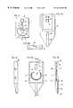
- FIGS. 1A-Dis a representation of a device of the invention described in Ser. No. 09/130,164.
- FIG. 2shows a membrane configuration for use in a device of this invention which is suitable for detecting one or several analytes with one semicircular detection zone and one narrow capture zone channel.
- the border of the semicircular detection zonewill connect to a sample circulation channel.
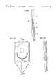
- FIGS. 3A-E, 4 A-B, and 5 A-Bshow the configuration of an example of a device of the present invention, and its component pieces, including the membrane holder, bottom piece, top piece, and sample delivery channel cover.
- FIGS. 6A-D, and 7 A-Dshow exploded view of examples of devices of the present invention, including cross-sectional views.
- FIG. 8shows the configuration of a membrane of this invention suitable for the detection of three different analytes via the biotin/streptavidin route, with three fluid pathways.
- FIGS. 9A-B, 10 , 11 A-B, 12 A-Bdepict devices of the invention with test reagent deposited in the sample delivery channel.
- Dry porous carrierand “dry porous carrier layer” refer to a cellular product through which the sample to be analyzed can move by capillary action.
- the dry porous carrier (layer)which in this art is often referred to as a membrane, is configured by closing off some of the porous areas so that the fluid to be analyzed moves along defined pathways through selected channels.
- Top layer or top pieceis a layer in the analytical test device which is configured to cooperate with a bottom layer or bottom piece to hold the dry porous carrier (membrane) layer when the top and bottom layers are placed in registry to provide, in cooperation with the dry porous layer, pathways which control the direction of flow of the sample to be analyzed through the device.
- Antigenis a molecule which, in an animal, induces the formation of an antibody.
- the devices of this inventionare useful for determining the presence of antigens in a fluid. They are especially useful for analyzing body fluids particularly whole blood, serum, plasma and urine. Antigens are often referred to as “analytes”.
- Cardiac analytesare analytes which are released into the blood as a result of cardiac tissue deterioration.
- Channelis any formed conduit through which the fluid sample under analysis flows in the analytical test device.
- a channelmay be formed in the top layer or in the porous carrier layer itself. Since the top layer is generally a rigid plastic such as a polyacrylate or polymethacrylate, a channel may be formed by molding, stamping, machining or any equivalent process.
- the channelsmay be formed by stamping the desired configuration into the layer. They may also be designed into the porous layer by forming non-porous boundaries with wax or ink. Channels are said to be in an operative communication when a fluid in one channel flows directly into another.
- “Semicircular”, as the word is used hereinis not limited to one half of a circle, but generally refers to a circle area where a sector has been removed or to this sector itself.
- “Circumscribed”, as the word is used hereinis not limited to an arcuate channel surrounding and conforming to a semicircular area of a porous membrane. The term includes—as will be apparent as this description continues—other configurations in which a sample circulation channel conforms with the border of one or more detection zones of other configurations, for instance when the area of the carrier is polygonal or forms part of a polygon.
- Essentiallyis a term used in connection with the distances between the points of sample entry into the detection zone and the entrance end of the capture zone channel. These distances should be as similar as possible. Obviously, a semicircular area on the carrier to which an arcuate sample circulation channel conforms is a highly preferred configuration because all resulting distances between the arcuate border of the detection zone and the entrance end of the capture zone channel are the same.
- Rapidmeans that a detectable product forms within a sufficiently short period of time, e.g. within about 5 to about 15 minutes, to permit the medical attendant to draw meaningful and useful conclusions.
- “Efficient”means that a detectable product can be formed with a low volume of fluid, e.g. a few drops of whole blood (from about 10 ⁇ l to about 80 ⁇ l), utilizing small amounts of reagents even when the antigen is present in very low concentrations as is usually the case with the cardiac analytes such as troponin I.
- FIG. 1Ais a perspective view and FIGS. 1B, 1 C and 1 D an exploded view of the invention of the previous application showing a top layer 16 , a support layer 28 , with a porous carrier 1 having a plastic backing layer 29 sandwiched between them.
- Through hole 17runs from the upper surface 30 through to the bottom surface 31 of the top layer 16 in registry with a sample delivery channel 18 formed in the bottom surface 31 of the top layer 16 .
- Sample delivery channel 18is in operative communication with a sample circulation channel 19 also formed in the bottom surface 31 of top layer 16 .
- the circulation channel 19is closed at both ends as shown by numeral 20 .
- the circulation channel 19is formed with inner walls 21 and outer walls 22 . As shown in FIG.
- top layer 16is attached to the support layer 28 by pins 34 which may be force fit into corresponding holes 35 . Any other equivalent means of attachment may be employed and the two layers 16 and 28 may be permanently or removably fixed.
- Porous carrier 1is shown in FIG. 1C with a backing 29 such as a polyester film. It is held between support layers 16 and 28 .
- the carrier 1may have the same exterior dimensions as layers 16 and 28 so long as there is an operative pathway through which the fluid added by way of through hole 17 can pass through the delivery channel 18 , the circulation channel 19 , the detection zones 50 , 51 and 52 , and the capture zone channels 27 a , 27 b and 27 c to the closed ends 12 and 20 , of the capture zone channels 27 a , 27 b , and 27 c ; and of circulation channel 19 , respectively.
- the porosity of the portion of the porous carrier 1 situated in contact with the sample delivery channel 18is destroyed in order to prevent the flow of sample in the membrane.
- the porous membrane 1 shown in FIG. 1Cis configured for the detection of three analytes. Accordingly it contains three detection zones or channels 50 , 51 and 52 , communicating with three capture zone channels 27 a , 27 b and 27 c , respectively.
- the contiguous arcuate border 11 of the detection zones 50 , 51 and 52extend over the inner walls 21 of circulation channel 19 so that the flow of fluid when stopped at ends 20 will flow by capillary action into the detection zones 50 , 51 and 52 .
- the flowis stopped at the ends 20 of the circulation channel to make it possible to control the size of the sample.
- An optional window 39 over an optional extension of the sample circulation channel shown as a dotted structure 53 in FIGS. 1A and 1B,may be provided to indicate that adequate sample has been applied to fill the channel.
- the corresponding portion of the carrier 1is blocked out to limit flow to the optional channel, as well as the corresponding portion of the carrier beneath the sample delivery channel.
- a further advantage of the design of the device of the inventionis that the same top and bottom layer pieces may be used for a variety of different devices.
- top layer 16is transparent, the formation of a visible reaction product will be readily apparent. If the top layer 16 is opaque it will be constructed with one or more viewing windows, shown in this example with a single window 37 , and a test end indicator window 38 . These one or more windows as shown in FIG. 1A will be in registry with the capture zone channels so that the operator can view the formation of colored products or adjust an instrument such as a reflectometer to determine if a detectable reaction product has formed.
- a optional test end indicator window 38is provided to indicate when the test is over by, for example, the presence of a dye in the porous carrier 1 upstream from the test end indicator window 38 but downstream from the portion of the porous carrier 1 under window 37 and the capture zone(s) 7 .
- the dyeis carried to the test end indicator window when sample has passed the capture zone.
- the capture zone channel 6may optionally contain a product 15 which reacts with any substance normally present in blood, plasma, serum or other body fluid to produce a visible product. This configuration may be provided on the porous carrier 1 either in window 37 or in the test end indicator window 38 .
- the device depicted in FIG. 1Ahas a single window for viewing the capture zone and a test end indicator window for purposes of illustration. In preferred devices, there will be one window extending transversely of the top surface 30 so that the results of all of the reactions can be viewed at once.
- FIGS. 1A-1Dthe dimensions of the sample delivery channel 18 are uniform throughout its length and that the membrane 1 extends well into the delivery channel. It is also noted that the porosity of the portion of the membrane situated under the sample delivery channel 18 is destroyed to prevent the sample from spreading along the porosity of the membrane.
- the devices of this inventionmay be employed to analyze a variety of liquid samples, especially biological samples which can be analyzed by conventional antigen/antibody reactions of either the competitive or sandwich variety utilizing labelled reactants which emit a detectable signal.
- liquid samplesespecially biological samples which can be analyzed by conventional antigen/antibody reactions of either the competitive or sandwich variety utilizing labelled reactants which emit a detectable signal.
- labelled reactantswhich emit a detectable signal.
- the inventionwill find its principal utility for the diagnosis of whole blood for the presence of cardiac analytes such as troponin I (TnI), troponin T, myoglobin, creative kinase MG CK-MB, myosin light chain, fatty acid binding protein, glycogen phosphorylase BB, actin and any of a host of other known analytes which are found in the blood as cardiac tissue deteriorates following an ischemic event such as angina or myocardial infarction. Accordingly, the invention will be principally described as utilized in the diagnosis of cardiac events.
- cardiac analytessuch as troponin I (TnI), troponin T, myoglobin, creative kinase MG CK-MB, myosin light chain, fatty acid binding protein, glycogen phosphorylase BB, actin and any of a host of other known analytes which are found in the blood as cardiac tissue deteriorates following an ischemic event such as angina or myocardial infarction.
- the devicemay be adapted for use to detect a wide variety of analytes by immunologic and other assay formats that take advantage of the separation of plasma from red blood cells in a chromatographic fluid flow of the device of the present invention.
- a single devicemay be configured to perform a plurality of assays of more than one format, for example an immunoassay and an enzyme-based assay, by providing the particular assay components in each of the separate fluid paths available in the device.
- the structures of the inventionare especially useful for analyzing blood, serum and plasma for CK-MB, myoglobin, myosin light chain, troponin I, troponin C, troponin T, and complexes of troponin I, troponin C, troponin T containing at least two troponin subunits as described in U.S. Pat. Nos. 5,747,274; 5,290,678; and 5,710,008, the entire contents of which are incorporated herein by reference.
- FIG. 2illustrates a dry porous carrier layer 1 (also referred to synonymously as membrane 1 ) of the invention configured for the analysis of whole blood for one analyte or a plurality of analytes by reactions between the analyte(s) and antibody pairs which react with different epitopes on the analyte in the classical antigen/antibody reaction utilizing polyclonal or monoclonal antibody pairs, one member of the selected pair being labelled.
- a dry porous carrier layer 1also referred to synonymously as membrane 1
- the figureshows carrier layer 1 in which the porosity of a selected section of the layer has been destroyed to leave only one porous area defining semicircular detection zone 3 with a border 11 and capture zone channel 6 which is closed at terminal end 12 .
- the porositymay be destroyed along the boundary of the zone referred to above, confining the sample to the interior of the boundary.
- This membrane 1which for analysis of whole blood is preferably nitrocellulose or equivalent material which chromatographically separates red blood cells to form a red blood cell front 13 and a plasma front 14 downstream thereof.
- nitrocellulose or equivalent materialwhich chromatographically separates red blood cells to form a red blood cell front 13 and a plasma front 14 downstream thereof.
- other materialsmay be preferable.
- the detection zone 3contains detection antibody 4 with detectable label 5 which reacts with the analyte, if present, to form a labelled antibody/antigen complex.
- the detection zone 3may contain several labelled antibodies.
- Antibody 4is mobile, i.e., it is movably deposited in the detection zone 3 by any of several known means so that the labelled antibody/analyte complex once formed is free to move downstream into the capture zone channel 6 for reaction with the capture antibody 7 fixed transverse of the capture zone channel 6 to form a detectable reaction product.
- the detection antibodymay be provided in the fluid path before the membrane, for example, in the form of beads or deposited material in the sample delivery channel, sample circulation channel, or in a chamber therebetween.
- capture antibody line 7is shown, but there may be a plurality of such lines, one for each analyte to be detected.
- Capture zone channel 6may optionally contain a product 15 which reacts with any substance normally present in the fluid to be analyzed to produce a visible control product indicating that fluid has passed the capture zone.
- the use of a control reactionis optional, but is preferred.
- the present applicationoffers further improvements over the above-mentioned devices.
- the device of the present inventionas shown in the example of FIGS. 3-5, has a sample delivery channel 18 which extends over the top surface of the device, covered by a cover piece 75 shown in FIG. 5 A.
- a sample delivery channel 18which extends over the top surface of the device, covered by a cover piece 75 shown in FIG. 5 A.
- Non-limiting examples of the components of the present devicewill described in further detail below.
- the advantages of the sample delivery channel on the top surface of the deviceare severalfold. First, the filling of the sample delivery channel can be viewed by the operator of the device, and, if the capacity of the sample delivery channel is equal to the amount of sample necessary to perform the test, application of sample may be stopped when the operator notes that the channel is completely filled.
- the sample delivery channelmay be placed at any suitable location on the top surface of the device, including placement over the portion of the device housing the membrane, as long as the sample delivery channel on the top surface of the top piece does not interfere with the membrane or other components of the device between the top and bottom pieces, or viewing or reading the results.
- Thisallows a smaller device to be provided, its size limited only to the size of the membrane.
- the reduced membrane size and the reduction or elimination of any extension of the device comprising the sample delivery channelprovides a smaller device with less membrane, reduces the cost of manufacture, packaging and shipping, and provides a more user-friendly and environmentally-friendly device.
- One convenient position for the sample delivery channelis such that the sample application hole of the device is at a location on the device which tapers to a point, such as is shown in FIG. 3 .
- Thisprovides a convenient means for filling the device with whole blood obtained by finger puncture, by holding the sample application opening 60 to the drop of blood, wherein the sample, usually 30 to 50 ⁇ l, is drawn by capillary action into and fills the sample delivery channel, after which the sample is conducted to the sample circulation channel and then onto the membrane.
- the sample delivery channelmay be preloaded with a dried test reagent, such as gold conjugated antibodies to the analyte, and/or biotinylated antibodies to the analyte, to operate the immunoassay as described herein.
- Preloadingmay comprise application of a solution comprising the reagent(s) which is then dried in the sample delivery channel, or placement of particles, for example, lyophilized beads comprising test reagents, in a defined recess or cavity in the channel.
- the dry reagentsdissolve in the sample and are carried along the fluid path.
- the section of the sample delivery channel 18 at location 92 near the junction of the circulation channel 19can be reduced in cross section so that there will be capillary movement of the sample into that section of the sample delivery channel 18 having the smaller volume.
- the particular advantage of this configurationis that the sample delivery channel 18 can be designed to hold the exact volume of sample needed to conduct the analysis. As the sample delivery channel fills with sample and the sample contacts the portion of the channel reduced in cross-section, capillary action will cause the sample to move to the further reduced cross-sectional portion and thus transfer the sample from the sample delivery channel to the sample circulation channel and initiate the chromatographic separation of plasma from blood and the immunoassay process.
- FIGS. 3-5show in detail the components of an example of a device of the present invention. Numerous alternate configurations are possible and are embraced by the invention herein. The skilled artisan will readily understand the other configurations possible, in particular, the further reduction in size of the device by placing the sample delivery channel over the membrane portion, as shown in FIG. 6 A and described in more detail below.
- FIG. 3Ashows a top view of the top piece 16 of the device, designed to hold the porous carrier 1 (membrane 1 ) between it and the bottom piece 28 shown in FIG. 4 .
- Top piece 16includes window 41 which is provided to allow the operator to view the capture zone 7 as well as an optional test-end indicator zone 15 on the membrane 1 .
- top piece 16also includes part of the sample delivery channel 18 , the sample circulation channel 19 , as seen from below in FIG. 3D, the latter having the same characteristics as that described in Ser. No. 130,164, herein incorporated by reference.
- FIG. 3Bshows a front view
- FIG. 3Ca side view, of the top piece.
- FIG. 3Eshows a composite, cross-sectional view of an example of an assembled device of the present invention, showing the top piece 16 , the bottom piece 28 , the sample delivery channel cover piece 75 .
- the figurealso shows the fluid path: the sample application port 60 , the sample delivery channel 18 , the narrowing junction 92 providing communication between the sample delivery channel 18 and the sample circulation channel, the membrane 1 , the window for viewing the capture zone(s) 41 , and the test-end indicator window 43 .
- test-end indicator zone 15contains a product which reacts with any substance normally present in the fluid to be analyzed to produce a visible control product viewable through window 43 .
- a productsuch as dye is deposited on the membrane 1 at location 15 not viewable through window 43 . The dye dissolves in the fluid and is carved to the end of the fluid path, 12 , where it is visible through window 43 .
- Top layer 16has an opening 60 for application of the sample.
- the sample delivery channel 18fills with the sample.
- capillary actiondrives the sample towards the sample circulation channel 19 and onto the membrane 1 .
- Sample delivery channel cover 75if transparent, allows the operator to view the filling of the sample delivery channel and indicates when it is completely filled.
- Sampleis conducted from the sample delivery channel to the circulation channel and onto the membrane.
- the sample circulation channelis configured to pass the sample onto the membrane.
- the instant deviceis suitable for measurement of one or more analytes using immunoassay procedures as well as other procedures, including enzyme-based assays.
- the discussion hereinrefers to an immunoassay procedure by way of non-limiting example.
- the samplepicks up the labeled detector antibody as it moves toward the capture channel, during which time analyte in the sample forms antibody-antigen complexes with the detector antibody.
- the samplewith the plasma front ahead of and separated from the red blood cell front, reaches the capture zone wherein analyte, with bound labeled antibody, interacts with and forms a sandwich with capture antibody.
- Accumulation of labeled antibody at the capture zoneindicates the presence of analyte in the sample.
- the operatorobserves in window for color at the capture zone(s).
- the labeled detector antibody, as well as other reagentsmay be placed in the sample delivery channel.
- sample delivery channel 18is in operative communication with the sample circulation channel 19 .
- Sample circulation channel 19is shown in an arcuate configuration in order to conform with the border 11 of the semicircular detection zone 3 of FIG. 2 .
- Sample circulation channel 19can be open or closed at both ends 20 . It is formed with inner wall 21 and outer wall 22 and is surrounded by a capillary trap 23 which functions to assure that the flow of sample is into the detection zone 3 of FIG. 2 at all points of border 11 , and then into the capture channel 6 at its entrance end 6 a.
- FIG. 4shows the detail of an example of a bottom piece 28 of the present invention.
- the bottom pieceholds the membrane 1 in place, and may have tabs 66 and 68 as shown which correspond with notches in the top piece 16 to facilitate fitting the pieces together to hold the membrane in the correction position.
- FIG. 4Bshows a front view of the bottom piece 28 as seen from the end with tabs 68
- FIG. 4Ca side view.
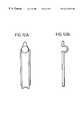
- FIGS. 5A and 5Bshow the sample delivery channel cover piece, from top and front views, respectively.
- the notched end 62represents the sample application area, as this end aligns with the end of the top piece 16 to form an opening, 60 .
- the pointed end of the coverrepresents the aspect which covers the portion of the sample delivery channel 18 which narrows to form a capillary channel 92 in communication with the sample circulation channel.
- the cover piece 75is attached to the top piece 16 by sliding the cover piece into the top piece along the sample delivery channel, the angled extensions 64 in the sides of the cover piece 75 sliding into corresponding longitudinal groves 69 running along the inside walls of the sample delivery channel in the top piece. Other means may be utilized in attaching the cover piece to the top piece, including adhesives, welding, etc.
- FIGS. 6-7show examples of other embodiments of the present invention, in particular, other positions for the sample delivery channel 18 .
- Top views, bottom views, and longitudinal sectionsare provided for two examples; views A show the top surface of the top pieces 16 , views the bottom surface of the top pieces 16 , views B a longitudinal section of the top pieces 16 , and views D the back pieces 28 .
- the sample delivery channelis situated over the section of the device containing the membrane, permitting the device to have a reduced size.
- the sample application port 60is on the side of the device.
- FIG. 7shows a device with an extension from the membrane-holding portion of the device, providing a longer device with the sample application port 60 at the end of the device.
- FIG. 8shows the configuration of a membrane 1 of the invention in which the biotin/streptavidin reaction is utilized to diagnose a whole blood sample for the presence of three analytes.
- the designmay be employed to ascertain the presence of several analytes such as myoglobin, troponin I or T and CK-MB in one small sample.
- the membrane 1is formed with three distinct pathways, one for each analyte leading from the borders 11 a , 11 b and 11 c of three separate detection zones 3 a , 3 b and 3 c .
- the detection zonesare separated by blocking segments 24 .
- the whole operative areais configured so as to provide three detection zones 3 a, b and c in operative communications at their borders 11 a , 11 b and 11 c with the sample circulation channel 19 on the lower surface of the upper layer 16 of the device.
- the detection zones 3 a , 3 b and 3 care in operative communication with the corresponding entrance bends 6 a , 6 b and 6 c of the respective capture zone channels.
- the detection zone 3 acontains two labelled antibodies, e.g. a biotin labelled antibody to CK-MB and a gold labelled antibody to CK-MB.
- black circlesstand for gold labelled antibodies while open circles stand for biotin labelled antibodies. No reference numerals are given for these detector antibodies in order not to clutter this figure.
- the red blood cell front in each of the three detection zones 3 a , 3 b , and 3 cis shown as 13 a , 13 b , and 13 c , respectively; the location of the respective plasma fronts are shown as 14 a , 14 b , and 14 c , respectively.
- CK-MBis present in the sample, the complex which forms will enter the capture channel at entrance 6 a to ultimately react with streptavidin at the streptavidin line 7 a to produce a visible product.
- analytesmay be similarly detected with conventional antigen antibody reactions.
- sandwich-type immunoassay depicted in the above exampleother immunoassay formats, including competitive assays, may be provided. Quantitation or semi-quantitation may be provided by utilizing various amounts of the different assay components.
- the devicemay carry out assays other than immunoassays.
- assaysother than immunoassays.
- interaction of the analyte with an enzyme or a series of enzymes, in the presence of the appropriate co-factors and chromogenic substrate(s)may result in the generation of a color in the sample indicative of the presence of analyte in the sample.
- the colormay be observed in the window 41 .
- the diagnostic devices of this inventionWhile, as aforesaid, it is preferred to design the diagnostic devices of this invention to detect more than one analyte, it is possible to design them with a single capture channel and multiple capture lines, one for each analyte, or with a plurality of capture channels each with a single capture line. This latter design, however, is not preferred because of the need for increased sample volume to ensure that reactions will take place in all channels. This defeats a principle aspect of the invention, namely to use the smallest sample with which it is possible to obtain useful results.
- a compromise which to some extent, but not completely alleviates the problemis to make the channels as small as possible and design them to be as close as possible to each other.
- the proximity of the channelsincreases the difficulty of reading the results with confidence because it is difficult to distinguish a capture line in one channel from a capture line in another.
- the devices of the inventioncan be configured to have more than one channel including the test channel and/or a negative and positive control channel. Multiple channels may each have more than one capture line. The designs will be readily apparent to the skilled artisan.
- One channelusually the middle channel will contain only fixed antibodies to the suspected analyte(s).
- the positive control channelwill contain mobile labeled antibodies at the entrance to the channel and fixed antibodies deeper in the channel.
- the negative control channelwill contain fixed antibodies, but will be blocked at its entrance to prevent the sample under test from entering.
- the negative test channelwill be designed with an entrance hole through the support member to permit the addition of an analyte free material such as a buffer which will migrate to the capture antibodies.
- the products and procedures of the inventionin addition to their value to test for cardiac analytes as described in detail above, may also be usefully employed in other medical procedures such as pregnancy and ovulation tests, such as by measurement of human chorionic gonadotropin (hCG) and luteinizing hormone (LH). They are especially useful to test for infections caused by particular viruses. For this utility they can be designed for both competitive and sandwich assays. They can be used to test for antigens, antibodies, surface antigens, and virus particles such as gp120 of the AIDS virus.
- hCGhuman chorionic gonadotropin
- LHluteinizing hormone
- the productscan be employed to test for drugs including drugs of abuse.
- Metal and enzyme labelsare preferred. Metal labels are especially preferred due to their remarkable sensitivity. Amongst the metals, gold is most preferred principally because it is so widely employed for this type of reaction and its characteristics are so well understood. Additionally, a gold signal can be enhanced to become more readily visible by the use of a soluble silver salt and a reducing agent in accordance with known procedures.
- the gold labelacts as a catalyst to reduce the silver salt to metallic silver, which deposits as a visible product.
- a typical reactive pairis silver lactate, which serves as the source of reducible silver ions, and hydroquinone as a reducing agent.
- the metallic silverforms a readily discernible black deposit around each particle of gold.
- the preferred particle size for gold labelled antibodies used in the inventionis from about 35 to 65 nm, although appreciable variation can be tolerated depending on well under stood factors such as the concentration of the analyte and the affinity of the reactants.
- reactionmay be detected by the addition of hydrogen peroxide and a dye such as ortho phenylenediamine in accordance with standard procedures.
- the preincubation zoneis employed to remove products present in the blood which may interfere with the desired reactions or make them difficult to detect.
- a typical interferantis the isoform of creatine kinase, CK-MM.
- Antibodies to the isoform CK-MBmay cross react with CK-MM and give false readings. This can be avoided by providing sufficient immobilized antibody to CK-MM in a preincubation zone upstream of the mobile antibody for CK-MB so that all of the CK-MM is removed before the moving sample reaches the detection antibody.
- the device employing the membrane of FIG. 8may utilize one or a plurality of labelled detector antibodies and capture antibodies in immobilized capture antibody lines. When several labelled detectors are employed care must be exercised to avoid interfering cross reactions. It is often best that the antibodies be arranged in more than one detection zone to react with their specific analytes as explained below in connection with the other figures.
- the device of the present inventionmay also be prepared to employ the biotin/avidin reaction utilizing variations such as those described above.
- a biotin labelled antibody and a gold labelled antibodyare movably placed in the detection zone 3 , where each of them reacts with a different epitope on the analyte to form a ternary complex composed of biotin labelled antibody/analyte/gold labelled antibody which moves by capillary action into and through the capture channel zone 6 where it reacts with avidin or streptavidin to concentrate and form a detectable reaction product.
- the antibodies employed in this inventionmay be either monoclonal or polyclonal.
- equivalents of the biotin/avidin reactioncan be employed. All of the reagents mentioned herein may be replaced with equivalents and are illustrative but not limitations of the invention.
- nitrocelluloseis preferred because it is readily available at reasonable cost. Nitrocellulose has been employed in chromatography and related fields for so many years that scientists and technicians are familiar with its properties. Commercially available nitrocellulose sheets can be readily formed into any selected formation with any selected configuration of channels.
- nitrocellulose membranes of the inventionmay be characterized as sponge-like with a plurality of interconnected micropores of various sizes and dimensions giving rise to capillary forces within the membrane. This permits the biological fluid under investigation to move along the selected pathway.
- the area, geometry and dimensions of the various devicesare so selected that the desired reactions take place in preselected areas as the liquid sample moves along predesigned pathways.
- these areasare selected on the basis of the relative speeds of the fronts of the red blood cell stream and the plasma stream, the kinetics of the desired reactions, the affinity of the antibodies for their respective epitopes and other factors which are well known to the skilled artisan or readily determined by conventional testing procedures.
- FIG. 8shows the configuration of a porous membrane with three fluid pathways, for use with three analytes, a single fluid pathway with three capture zones may also be provided, and as noted above, is preferred.
- One of the advantages of this inventionis that the devices whether intended to measure one, two or three antigens can have the same dimensions.
- the porous carrier layer 1will be designed differently in each case.
- the top layer 16does not require any changes to fit differently designed carrier layers 1 .
- the detector antibodymay be provided in the form of, for example, lyophilized beads, such as a single larger bead or multiple smaller beads, placed within the fluid path upstream from the membrane, such that the bead dissolves in the fluid.
- lyophilized beadssuch as a single larger bead or multiple smaller beads
- the beadmay be provided in a sample delivery channel, the sample circulation channel, or at their junction; a small cavity may be provided in the sample delivery channel or at the junction between the sample delivery channel 18 and the sample circulation channel 19 , to hold the material.
- the antibodyis deposited in lyophilized form within the channel.
- Other reagentsmay be so provided, such as reagents to remove interfering substances, as described above.
- reagents common to the assaysmay be provided in the fluid path prior to the membrane, and reagents specific to each assay provided in the particular detection zone of the membrane as described above.
- porous carriersare those which, if used as a filter, that is filtering particles from a liquid stream flowing vertically to the horizontal surface of the membrane, will prevent the passage of particles larger than from 3 to 12 ⁇ m.
- the pore sizedecreases, the mobility of a fluid within the membrane decreases, thereby increasing the time required for diagnosis. If the pores are too large, the time of passage reduces with the result that the reactants are not in contact with each other for a sufficient period for the diagnostic reactions to occur, or to occur to such a limited extent that they do not provide the desired information.
- Nitrocellulose membranes with supporting polyester or other filmsare commercially available. These are preferred for use in this invention since unsupported membranes tend to be quite fragile, susceptible to fracture and difficult to handle in a mass production environment. Moreover, the films are impervious to the flowing fluids so that they do not interfere with the flow of liquid samples through the chosen pathways of the devices of this invention.
- One such membraneis available to a variety of pore sizes from Gerbermembrane of Gerbershausen, Germany.
- the antibodies employed in this inventionare prepared by standard techniques. See for example, Falfre, Howe, Milstein et al., Nature Vol. 266, 7, 550-552, April 1977. The disclosure of this seminal article on the preparation of monoclonal antibodies is incorporated herein by reference.
- Nitrocelluloseis an avid binder for proteins.
- the labelled detector antibodymay be movably affixed to the membrane by first saturating the detector zone with another protein such as bovine serum albumin. Alternate locations for the detector antibodies are noted above.
- a cavity 100is provided at the junction between the sample delivery channel and the sample circulation channel to contain a bead or other form of reagents such as lyophilized labeled detector antibody, which will dissolve in the fluid to be analyzed as it passes through this region of the device.
- FIG. 9Aalso shows a test end indicator window 43 and a corresponding strip of reagent on the membrane just upstream from this window. The fluid dissolves and carries this reagent into view of window 43 to indicate the test is finished.
- the detector antibody at position 100is present in the sample delivery channel.
- FIGS. 11A-11B and 12 A- 12 Bshow other variations in the design of the device to comprise a cavity to contain reagents in dried or bead form, in particular, a concavity.
- the reagents provided in the fluid pathmay include labeled detector antibody(ies) as well as other reagents needed to perform the test, including those needed to remove interfering substances that may be present in the sample. Reagents may be provided both on the membrane and in the fluid path, as needed.
- reagentsmay be provided both on the membrane and in the fluid path, as needed.
- the reagents provided in the devicemust not cause lysis of the red blood cells in the sample, to permit the separation.
- the device of this inventioncan be readily manufactured by procedures already well known in the art.
- Enzyme-based assayssuch as the quantitation of glucose in whole blood using the combination of glucose oxidase and peroxidase, with the appropriate reactants and chromogenic substrate to generate a color in proportion to the level of glucose in the sample, may be configured to operate using a device of this invention.
- the skilled artisanwill recognize the adaptability of other assay formats to the present device.
- a control lineis prepared with a solution containing 80 ⁇ l of a 4% (w/v) solution of sucrose (from Sigma-Aldrich GmbH, Steinheim, Germany), 10 ⁇ l of water and 10 ⁇ l of a 1 mg/ml solution of recombinant CK-MB (from Spectral Diagnostics, Toronto, Canada). After drying, the membrane is impregnated with a blocking solution containing in final concentrations: 0.06% (w/w) Octyl-beta-D-Gluco-pyranoside (from Fluka Chemie AG, Buchs, Switzerland), 1:30 dilution of Kasein-Bindeffen (from H.
- the gold-conjugate solutionis prepared with a 40 nm gold sol loaded with 22 ⁇ g/ml of the antibody 5CKMB-6 from Spectral Diagnostics, Toronto, at an OD (520 nm) of 10 prepared by British Biocell International, Edinburgh, UK.
- OD520 nm
- the biotinylated antibody solutionis prepared with the antibody 1rCKMB-28 from Spectral Diagnostics, Toronto as described to 57 ⁇ l of water 20 ⁇ l of a 6% (w/v) aqueous solution of Crotein C and 3 ⁇ l of a 2 mg/ml stock solution of the biotinylated antibody solution are added and mixed.
- testsare prepared as in 1A) but without the biotinylated antibody solution, and instead of the streptavidin capture line an antibody capture line is prepared with the antibody 1rCKMB-28 (from Spectral Diagnostics, Toronto) at a concentration of 13 mg/ml.
- Heparinized whole bloodis spiked with rCKMB at indicated concentrations and 28 ⁇ l are applied to the test.
- the results(within 6-7 min.) are as follows:
- sample entry in a semicircular area(circle segment) (FIGS. 4 and 5) is compared with a sample entry in a rectangular configuration, i.e. from 3 sides (FIGS. 9 and 10 ).
- the test areas(contour areas) are in both cases the same. Beside the contour shape and blood entry directions all other procedures are as in example 1A).
- test as in example 1Bis prepared, but in addition to the CKMB antibody capture line there is a TNI antibody capture line and a Myoglobin antibody capture line.
- TNI capture13 mg/ml polyclonal goat TNI
- Myoglobin capture13 mg/ml polyclonal rabbit Myoglobin
- Gold-conjugates for the 3 analytesare from British Biocell Intern., Cambridge, UK:
- TNI-gold-a40 nm gold sol loaded with 8 ⁇ l/ml 81-7 antibody (OD 10)
- TNI-gold-b40 nm gold sol loaded with 16 ⁇ g/ml 21-14 antibody (OD 10)
- Myoglobin-gold15 nm loaded with 90 ⁇ g/ml 2 Mb-295 antibody (OD 10)
- CKMB-gold40 nm gold sol loaded with 22 ⁇ g/ml 5CKMB-6 (OD 10)
- the TNI gold conjugate solutioncontains: 15 ⁇ l of TNI-gold-a at an OD of 33, 30 ⁇ l of TNI-gold-b at an OD of 33, 45 ⁇ l water and 10 ⁇ l of a 2.5% (w/v) aqueous solution of Crotein C.
- the CKMB/Myoglobin gold conjugate solutioncontains: 48 ⁇ l of CKMB-gold at an OD of 33, 25 ⁇ l of Myoglobin-gold at an OD of 6, 17 ⁇ l water and 10 ⁇ l of a 2.5% aqueous solution of Crotein C. 2 ⁇ l of this solution is applied to the test area.
- Heparinized whole bloodis spiked with rCKMB, TNI and Myoglobin at indicated concentrations, and 28 ⁇ l are applied to the test.
- the resultsare as follows:
- FIG. 11For more than one analyte with high sensitivity a contour as in FIG. 11 is used.
- the capture linesare prepared with streptavidin (13 mg/ml) as in Example 1A (the blocking procedure likewise).
- the contouris drawn with Paint Marker 780 white (from Edding AG, Ahrensburg, Germany).
- TNI-gold conjugateThe following solutions are mixed:
- 18 ⁇ l gold conjugate A with an OD of 55(50 nm gold sol loaded with 18 ⁇ g/ml of the antibody 81-7 at OD 10)
- 36 ⁇ l gold conjugate B with an OD of 55(60 nm gold sol loaded with 10 ⁇ g/ml of the antibody 21-14 at OD 10)
- Biotinylated TNI-antibodiesThe following solutions are mixed: 67 ⁇ l water, 25 ⁇ l of a 6% (w/v) aqueous solution of Crotein C, 3.5 ⁇ l of a 1 mg/ml stock solution of biotinylated goat TNI antibodies and 5 ⁇ l of a 27.6 mg/ml solution of Chrom Pure Goat IgG (from Jackson Immuno Research Laboratories Inc.). 2.1 ⁇ l of this solution is applied to the test area.
- CKMB-gold conjugateAs in example 1A), except that the OD of the stock solution is 33, and 1.1 ⁇ l of the mixture is applied.
- Biotinylated CKMB-antibodiesAs in example 1A), except that 1.4 ⁇ l is applied.
- Myoglobin-gold conjugateThe following solutions are mixed: 17 ⁇ l of a gold conjugate with an OD of 6 (15 nm gold sol loaded with 90 ⁇ g/ml of the antibody 2 Mb-295 at OD 10), 73 ⁇ l water and 10 ⁇ l of a 2.5% (w/v) aqueous solution of Crotein C. 0.8 ⁇ l of this mixture is applied to the test.
- Biotinylated Myoglobin-antibodiesThe following solutions are mixed: 45 ⁇ l water, 25 ⁇ l of a 6% (w/v) aqueous solution of Crotein C and 30 ⁇ l of a 1 mg/ml stock solution of biotinylated rabbit antibodies Myoglobin. 0.5 ⁇ l of this mixture is applied to the test.
- Heparinized whole bloodis spiked with rCK, TNI and Myoglobin at indicated concentrations, and 70 ⁇ l is applied to the test.
Landscapes
- Health & Medical Sciences (AREA)
- Immunology (AREA)
- Life Sciences & Earth Sciences (AREA)
- Engineering & Computer Science (AREA)
- Molecular Biology (AREA)
- Biomedical Technology (AREA)
- Chemical & Material Sciences (AREA)
- Hematology (AREA)
- Urology & Nephrology (AREA)
- Biotechnology (AREA)
- Microbiology (AREA)
- Cell Biology (AREA)
- Food Science & Technology (AREA)
- Medicinal Chemistry (AREA)
- Physics & Mathematics (AREA)
- Analytical Chemistry (AREA)
- Biochemistry (AREA)
- General Health & Medical Sciences (AREA)
- General Physics & Mathematics (AREA)
- Pathology (AREA)
- Investigating Or Analysing Biological Materials (AREA)
Abstract
Description
| rCKMB | Streptavidin- | Antibody- |
| in ng/ml | Capture | Capture |
| 0 | − | − |
| 5 | + | n.d. |
| 20 | + + | n.d. |
| 80 | + + + + | + |
| − = no visible signal line | ||
| + + + + = strong signal line | ||
| n.d. = not determined | ||
| All control lines are positive. | ||
| rCKMB | circle segment | rectangular | ||
| in ng/ml | signal | test time | signal | test time |
| 0 | − | 6.5 min. | − | 7.5 min. |
| 20 | ++ | 7.0 min. | ++ | 7.5 min. |
| Signal |
| TNI-capture | CKMB-capture | Myoglobin-capture | ||
| 0 ng/ml TNI | − | ||
| 0 ng/ml CKMB | − | ||
| 0 ng/ml Myoglobin | trace | ||
| 2 ng/ml TNI | + | ||
| 2 ng/ml CKMB | + | ||
| 200 ng/ml | + + | ||
| Myoglobin | |||
| Signal |
| TNI | CKMB | Myoglobin | ||
| 0 ng/ml TNI | − | ||||
| 0 ng/ml CKMB | − | ||||
| 0 ng/ml Myoglobin | − | ||||
| 2 ng/ml TNI | + + | ||||
| 20 ng/ml CKMB | + + | ||||
| 200 ng/ml Myoglobin | + + | ||||
| 10 ng/ml TNI | + + + + | ||||
| 100 ng/ml CKMB | + + + + | ||||
| 700 ng/ml Myoglobin | + + + + | ||||
Claims (62)
Priority Applications (15)
| Application Number | Priority Date | Filing Date | Title |
|---|---|---|---|
| US09/353,190US6214629B1 (en) | 1998-08-06 | 1999-07-14 | Analytical test device and method for use in medical diagnoses |
| DE69906986TDE69906986T2 (en) | 1998-08-06 | 1999-08-06 | ANALYTICAL TEST APPARATUS AND METHOD |
| PCT/EP1999/005712WO2000008466A2 (en) | 1998-08-06 | 1999-08-06 | Analytical test device and method |
| MXPA01001384AMXPA01001384A (en) | 1998-08-06 | 1999-08-06 | Analytical test device and method. |
| CNB2004100039525ACN1250970C (en) | 1998-08-06 | 1999-08-06 | Analytical test device and method |
| CNB998110566ACN1145027C (en) | 1998-08-06 | 1999-08-06 | Analytical assay device and method for determining the presence of at least one analyte in a fluid sample |
| CA002339599ACA2339599A1 (en) | 1998-08-06 | 1999-08-06 | Analytical test device and method |
| JP2000564049AJP2002522767A (en) | 1998-08-06 | 1999-08-06 | Analytical test apparatus and method |
| AT99940165TATE237807T1 (en) | 1998-08-06 | 1999-08-06 | ANALYTICAL TEST APPARATUS AND METHOD |
| EP99940165AEP1102989B1 (en) | 1998-08-06 | 1999-08-06 | Analytical test device and method |
| HK01108465.8AHK1039518B (en) | 1998-08-06 | 1999-08-06 | Analytical test device and method |
| AU54208/99AAU764444B2 (en) | 1998-08-06 | 1999-08-06 | Analytical test device and method |
| KR1020017001614AKR100604510B1 (en) | 1998-08-06 | 1999-08-06 | Analytical Test Apparatus and Methods |
| US09/777,549US6673628B2 (en) | 1998-08-06 | 2001-02-06 | Analytical test device and method |
| AU2003262455AAU2003262455A1 (en) | 1998-08-06 | 2003-11-21 | Analytical test device and method |
Applications Claiming Priority (2)
| Application Number | Priority Date | Filing Date | Title |
|---|---|---|---|
| US09/130,164US6171870B1 (en) | 1998-08-06 | 1998-08-06 | Analytical test device and method for use in medical diagnoses |
| US09/353,190US6214629B1 (en) | 1998-08-06 | 1999-07-14 | Analytical test device and method for use in medical diagnoses |
Related Parent Applications (2)
| Application Number | Title | Priority Date | Filing Date |
|---|---|---|---|
| US09/130,164Continuation-In-PartUS6171870B1 (en) | 1998-08-06 | 1998-08-06 | Analytical test device and method for use in medical diagnoses |
| US09/353,188ContinuationUS6410341B1 (en) | 1998-08-06 | 1999-07-14 | Analytical test device and method for use in medical diagnoses |
Related Child Applications (1)
| Application Number | Title | Priority Date | Filing Date |
|---|---|---|---|
| PCT/EP1999/005712ContinuationWO2000008466A2 (en) | 1998-08-06 | 1999-08-06 | Analytical test device and method |
Publications (1)
| Publication Number | Publication Date |
|---|---|
| US6214629B1true US6214629B1 (en) | 2001-04-10 |
Family
ID=46256560
Family Applications (1)
| Application Number | Title | Priority Date | Filing Date |
|---|---|---|---|
| US09/353,190Expired - LifetimeUS6214629B1 (en) | 1998-08-06 | 1999-07-14 | Analytical test device and method for use in medical diagnoses |
Country Status (1)
| Country | Link |
|---|---|
| US (1) | US6214629B1 (en) |
Cited By (100)
| Publication number | Priority date | Publication date | Assignee | Title |
|---|---|---|---|---|
| US20040023309A1 (en)* | 2001-11-27 | 2004-02-05 | Franz Noll | Immunoassay and kit for an early and simultaneous detection of biochemical markers in a patient's sample |
| US20040082077A1 (en)* | 2002-10-24 | 2004-04-29 | Wei Hu | Diagnostic device for analyte detection |
| US20040191889A1 (en)* | 2001-06-15 | 2004-09-30 | Lalit Mahajan | See through testing device |
| WO2005045408A1 (en)* | 2003-10-28 | 2005-05-19 | American Bio Medica Corporation | Lateral flow immunoassay device |
| US20060015019A1 (en)* | 2002-06-25 | 2006-01-19 | Watt Paul W | Wound fluid collecting and indicating device |
| US20060019406A1 (en)* | 2004-07-23 | 2006-01-26 | Ning Wei | Lateral flow device for the detection of large pathogens |
| WO2006031216A1 (en)* | 2004-09-10 | 2006-03-23 | Metrika, Inc. | Quantitative immunoassays using tag/anti-tag chemistry |
| US20060068500A1 (en)* | 2004-09-28 | 2006-03-30 | Kimberly-Clark Worldwide, Inc. | Detecting yeast infections using a lateral flow assay |
| US20060205086A1 (en)* | 2002-10-24 | 2006-09-14 | Spectral Diagnostics Inc. | Diagnostic device |
| US20070042444A1 (en)* | 2003-03-28 | 2007-02-22 | Ani Biotech Oy | Multiple-channel test device, method for producing the same and use thereof |
| US20070083090A1 (en)* | 2005-10-06 | 2007-04-12 | Sterling Bernhard B | System and method for determining a treatment dose for a patient |
| US20070202542A1 (en)* | 2004-11-01 | 2007-08-30 | Babu Uma M | Disposable immunodiagnostic test system |
| KR100841355B1 (en) | 2006-04-04 | 2008-07-01 | 주식회사 올메디쿠스 | Biosensor chip with non-powered blood separation means |
| US20080166820A1 (en)* | 2007-01-09 | 2008-07-10 | Martin Gould | Extraction method and apparatus for high-sensitivity body fluid testing device |
| US20080305548A1 (en)* | 2007-06-11 | 2008-12-11 | American Bio Medica Corporation | Method for stimulating saliva production during oral sample collection procedure |
| US20090061534A1 (en)* | 2007-09-01 | 2009-03-05 | Stephen Paul Sharrock | Assay Device with Shared Zones |
| US20090131861A1 (en)* | 2007-10-10 | 2009-05-21 | Optiscan Biomedical Corporation | Fluid component analysis system and method for glucose monitoring and control |
| US20090170062A1 (en)* | 2004-02-02 | 2009-07-02 | Peter Schwind | Device and method for detecting analytes by visualization and separation of agglutination |
| US20100137145A1 (en)* | 2005-06-28 | 2010-06-03 | Zbx Corporation | Membrane array and analytical device |
| US20100209297A1 (en)* | 2007-04-10 | 2010-08-19 | Inverness Medical Switzerland Gmbh | Assay Device |
| US20100240964A1 (en)* | 2005-02-14 | 2010-09-23 | Sterling Bernhard B | System and method for determining a treatment dose for a patient |
| US20110003371A1 (en)* | 2002-10-11 | 2011-01-06 | Qinwei Shi | Diagnostic devices |
| US20110111449A1 (en)* | 2001-11-08 | 2011-05-12 | Braig James R | In vitro determination of analyte levels within body fluids |
| US20110136143A1 (en)* | 2005-11-18 | 2011-06-09 | The Government Of The United States Of America, As Represented By The Secretary Of The Department Of | Modified cardiolipin and uses therefor |
| CN102124338A (en)* | 2008-08-26 | 2011-07-13 | 红电医学科技股份有限公司 | Base plate of fluid detection test piece |
| US20120077281A1 (en)* | 2010-09-24 | 2012-03-29 | Beal John Harley Loveless | Antioxidant Test Device |
| US20130052655A1 (en)* | 2010-03-31 | 2013-02-28 | Sekisui Medical Co., Ltd. | Assay utilizing immunochromatography, immunochromatographic test strip, and assay reagent kit for immunochromatography |
| US8417311B2 (en) | 2008-09-12 | 2013-04-09 | Optiscan Biomedical Corporation | Fluid component analysis system and method for glucose monitoring and control |
| US8546148B2 (en) | 2010-06-14 | 2013-10-01 | Siemens Healthcare Diagnostics Inc | Composition for use as an assay reagent |
| US8778619B2 (en) | 2005-11-18 | 2014-07-15 | The United States Of America As Represented By The Secretary Of The Department Of Health And Human Services | Oxidized cardiolipin and uses to detect cardiolipin antibodies |
| US8928877B2 (en) | 2011-07-06 | 2015-01-06 | Optiscan Biomedical Corporation | Sample cell for fluid analysis system |
| US8936755B2 (en) | 2005-03-02 | 2015-01-20 | Optiscan Biomedical Corporation | Bodily fluid composition analyzer with disposable cassette |
| US8992443B2 (en) | 2005-02-14 | 2015-03-31 | Optiscan Biomedical Corporation | Fluid handling cassette |
| US9091676B2 (en) | 2010-06-09 | 2015-07-28 | Optiscan Biomedical Corp. | Systems and methods for measuring multiple analytes in a sample |
| US9180449B2 (en) | 2012-06-12 | 2015-11-10 | Hach Company | Mobile water analysis |
| US9182353B2 (en) | 2010-07-22 | 2015-11-10 | Hach Company | Lab-on-a-chip for alkalinity analysis |
| US9289169B2 (en) | 2007-05-18 | 2016-03-22 | Optiscan Biomedical Corp. | Analyte monitoring systems and methods |
| USD768872S1 (en) | 2012-12-12 | 2016-10-11 | Hach Company | Cuvette for a water analysis instrument |
| US20160327460A1 (en)* | 2013-11-08 | 2016-11-10 | Espci | Method and support for storing and concentrating a non-volatile compound |
| US9506886B1 (en)* | 2014-04-30 | 2016-11-29 | Helvetia Wireless Llc | Systems and methods for detecting a liquid |
| US9523682B2 (en) | 2011-11-16 | 2016-12-20 | Becton, Dickinson And Company | Methods and systems for detecting an analyte in a sample |
| US9554742B2 (en) | 2009-07-20 | 2017-01-31 | Optiscan Biomedical Corporation | Fluid analysis system |
| US9561001B2 (en) | 2005-10-06 | 2017-02-07 | Optiscan Biomedical Corporation | Fluid handling cassette system for body fluid analyzer |
| US9649061B2 (en) | 2015-03-10 | 2017-05-16 | Becton, Dickinson And Company | Biological fluid micro-sample management device |
| US9678065B2 (en) | 2013-01-11 | 2017-06-13 | Becton, Dickinson And Company | Low-cost point-of-care assay device |
| US9693723B2 (en) | 2014-10-14 | 2017-07-04 | Becton, Dickinson And Company | Blood sample management using open cell foam |
| US9797899B2 (en) | 2013-11-06 | 2017-10-24 | Becton, Dickinson And Company | Microfluidic devices, and methods of making and using the same |
| US9851364B2 (en) | 2008-06-04 | 2017-12-26 | Alere Switzerland Gmbh | Assay reader, device and method of measuring HCG |
| US9863837B2 (en) | 2013-12-18 | 2018-01-09 | OptiScan Biomedical Coporation | Systems and methods for detecting leaks |
| US9981264B2 (en) | 2014-11-04 | 2018-05-29 | Grace Bio-Labs, Inc. | Nitrocellulose extrusion for porous film strips |
| US10018640B2 (en) | 2013-11-13 | 2018-07-10 | Becton, Dickinson And Company | Optical imaging system and methods for using the same |
| US10201303B2 (en) | 2009-07-20 | 2019-02-12 | Optiscan Biomedical Corporation | Fluid analysis system |
| US10533994B2 (en) | 2006-03-24 | 2020-01-14 | Theranos Ip Company, Llc | Systems and methods of sample processing and fluid control in a fluidic system |
| US10578606B2 (en) | 2015-09-01 | 2020-03-03 | Becton, Dickinson And Company | Depth filtration device for separating specimen phases |
| US10761030B2 (en) | 2005-05-09 | 2020-09-01 | Labrador Diagnostics Llc | System and methods for analyte detection |
| US11215610B2 (en) | 2006-10-13 | 2022-01-04 | Labrador Diagnostics Llc | Reducing optical interference in a fluidic device |
| US11287421B2 (en) | 2006-03-24 | 2022-03-29 | Labrador Diagnostics Llc | Systems and methods of sample processing and fluid control in a fluidic system |
| US11298061B2 (en) | 2014-10-14 | 2022-04-12 | Becton, Dickinson And Company | Blood sample management using open cell foam |
| US11324889B2 (en) | 2020-02-14 | 2022-05-10 | Insulet Corporation | Compensation for missing readings from a glucose monitor in an automated insulin delivery system |
| US11386996B2 (en) | 2014-01-30 | 2022-07-12 | Insulet Netherlands B.V. | Therapeutic product delivery system and method of pairing |
| US11439754B1 (en) | 2021-12-01 | 2022-09-13 | Insulet Corporation | Optimizing embedded formulations for drug delivery |
| US11547800B2 (en) | 2020-02-12 | 2023-01-10 | Insulet Corporation | User parameter dependent cost function for personalized reduction of hypoglycemia and/or hyperglycemia in a closed loop artificial pancreas system |
| US11551802B2 (en) | 2020-02-11 | 2023-01-10 | Insulet Corporation | Early meal detection and calorie intake detection |
| US11565043B2 (en) | 2018-05-04 | 2023-01-31 | Insulet Corporation | Safety constraints for a control algorithm based drug delivery system |
| US11565039B2 (en) | 2018-10-11 | 2023-01-31 | Insulet Corporation | Event detection for drug delivery system |
| US11596740B2 (en) | 2015-02-18 | 2023-03-07 | Insulet Corporation | Fluid delivery and infusion devices, and methods of use thereof |
| US11607493B2 (en) | 2020-04-06 | 2023-03-21 | Insulet Corporation | Initial total daily insulin setting for user onboarding |
| US11628251B2 (en) | 2018-09-28 | 2023-04-18 | Insulet Corporation | Activity mode for artificial pancreas system |
| US11684716B2 (en) | 2020-07-31 | 2023-06-27 | Insulet Corporation | Techniques to reduce risk of occlusions in drug delivery systems |
| US11724027B2 (en) | 2016-09-23 | 2023-08-15 | Insulet Corporation | Fluid delivery device with sensor |
| US11738144B2 (en) | 2021-09-27 | 2023-08-29 | Insulet Corporation | Techniques enabling adaptation of parameters in aid systems by user input |
| US11801344B2 (en) | 2019-09-13 | 2023-10-31 | Insulet Corporation | Blood glucose rate of change modulation of meal and correction insulin bolus quantity |
| US11833329B2 (en) | 2019-12-20 | 2023-12-05 | Insulet Corporation | Techniques for improved automatic drug delivery performance using delivery tendencies from past delivery history and use patterns |
| US11857763B2 (en) | 2016-01-14 | 2024-01-02 | Insulet Corporation | Adjusting insulin delivery rates |
| US11865299B2 (en) | 2008-08-20 | 2024-01-09 | Insulet Corporation | Infusion pump systems and methods |
| US11904140B2 (en) | 2021-03-10 | 2024-02-20 | Insulet Corporation | Adaptable asymmetric medicament cost component in a control system for medicament delivery |
| US11929158B2 (en) | 2016-01-13 | 2024-03-12 | Insulet Corporation | User interface for diabetes management system |
| US11935637B2 (en) | 2019-09-27 | 2024-03-19 | Insulet Corporation | Onboarding and total daily insulin adaptivity |
| USD1020794S1 (en) | 2018-04-02 | 2024-04-02 | Bigfoot Biomedical, Inc. | Medication delivery device with icons |
| US11957875B2 (en) | 2019-12-06 | 2024-04-16 | Insulet Corporation | Techniques and devices providing adaptivity and personalization in diabetes treatment |
| USD1024090S1 (en) | 2019-01-09 | 2024-04-23 | Bigfoot Biomedical, Inc. | Display screen or portion thereof with graphical user interface associated with insulin delivery |
| US11969579B2 (en) | 2017-01-13 | 2024-04-30 | Insulet Corporation | Insulin delivery methods, systems and devices |
| US11986630B2 (en) | 2020-02-12 | 2024-05-21 | Insulet Corporation | Dual hormone delivery system for reducing impending hypoglycemia and/or hyperglycemia risk |
| US12036389B2 (en) | 2020-01-06 | 2024-07-16 | Insulet Corporation | Prediction of meal and/or exercise events based on persistent residuals |
| US12042630B2 (en) | 2017-01-13 | 2024-07-23 | Insulet Corporation | System and method for adjusting insulin delivery |
| US12064591B2 (en) | 2013-07-19 | 2024-08-20 | Insulet Corporation | Infusion pump system and method |
| US12076160B2 (en) | 2016-12-12 | 2024-09-03 | Insulet Corporation | Alarms and alerts for medication delivery devices and systems |
| US12097355B2 (en) | 2023-01-06 | 2024-09-24 | Insulet Corporation | Automatically or manually initiated meal bolus delivery with subsequent automatic safety constraint relaxation |
| US12106837B2 (en) | 2016-01-14 | 2024-10-01 | Insulet Corporation | Occlusion resolution in medication delivery devices, systems, and methods |
| US12115351B2 (en) | 2020-09-30 | 2024-10-15 | Insulet Corporation | Secure wireless communications between a glucose monitor and other devices |
| US12121700B2 (en) | 2020-07-22 | 2024-10-22 | Insulet Corporation | Open-loop insulin delivery basal parameters based on insulin delivery records |
| US12121701B2 (en) | 2021-01-29 | 2024-10-22 | Insulet Corporation | Systems and methods for incorporating co-formulations of insulin in an automatic insulin delivery system |
| US12128215B2 (en) | 2020-09-30 | 2024-10-29 | Insulet Corporation | Drug delivery device with integrated optical-based glucose monitor |
| CN119875815A (en)* | 2025-03-24 | 2025-04-25 | 良渚实验室 | Gold ball sensitization type abnormal-hole micro-channel array biological reaction chip and application thereof |
| US12318577B2 (en) | 2017-01-13 | 2025-06-03 | Insulet Corporation | System and method for adjusting insulin delivery |
| US12343502B2 (en) | 2017-01-13 | 2025-07-01 | Insulet Corporation | System and method for adjusting insulin delivery |
| US12370307B2 (en) | 2020-02-03 | 2025-07-29 | Insulet Corporation | Use of fuzzy logic in predicting user behavior affecting blood glucose concentration in a closed loop control system of an automated insulin delivery device |
| US12383166B2 (en) | 2016-05-23 | 2025-08-12 | Insulet Corporation | Insulin delivery system and methods with risk-based set points |
| US12406760B2 (en) | 2021-06-07 | 2025-09-02 | Insulet Corporation | Exercise safety prediction based on physiological conditions |
| US12431229B2 (en) | 2021-03-10 | 2025-09-30 | Insulet Corporation | Medicament delivery device with an adjustable and piecewise analyte level cost component to address persistent positive analyte level excursions |
Citations (21)
| Publication number | Priority date | Publication date | Assignee | Title |
|---|---|---|---|---|
| US4477575A (en) | 1980-08-05 | 1984-10-16 | Boehringer Mannheim Gmbh | Process and composition for separating plasma or serum from whole blood |
| US4753776A (en) | 1986-10-29 | 1988-06-28 | Biotrack, Inc. | Blood separation device comprising a filter and a capillary flow pathway exiting the filter |
| US4774192A (en) | 1987-01-28 | 1988-09-27 | Technimed Corporation | A dry reagent delivery system with membrane having porosity gradient |
| US4861711A (en) | 1984-12-15 | 1989-08-29 | Behringwerke Aktiengesellschaft | Sheet-like diagnostic device |
| US4933092A (en) | 1989-04-07 | 1990-06-12 | Abbott Laboratories | Methods and devices for the separation of plasma or serum from whole blood |
| US4987065A (en) | 1983-07-05 | 1991-01-22 | Enzo Biochem, Inc. | In vivo labelling of polynucleotide sequences |
| US5075078A (en) | 1989-10-05 | 1991-12-24 | Abbott Laboratories | Self-performing immunochromatographic device |
| US5079142A (en) | 1987-01-23 | 1992-01-07 | Synbiotics Corporation | Orthogonal flow immunoassays and devices |
| US5096809A (en) | 1988-07-25 | 1992-03-17 | Pacific Biotech, Inc. | Whole blood assays using porous membrane support devices |
| US5110724A (en) | 1990-04-02 | 1992-05-05 | Cholestech Corporation | Multi-analyte assay device |
| US5120643A (en) | 1987-07-13 | 1992-06-09 | Abbott Laboratories | Process for immunochromatography with colloidal particles |
| US5135716A (en) | 1989-07-12 | 1992-08-04 | Kingston Diagnostics, L.P. | Direct measurement of HDL cholesterol via dry chemistry strips |
| US5141850A (en) | 1990-02-07 | 1992-08-25 | Hygeia Sciences, Inc. | Porous strip form assay device method |
| US5144890A (en) | 1989-10-25 | 1992-09-08 | Valmet-Ahlstrom Inc. | Actuator of modular construction for rolls of a machine calender |
| US5290678A (en) | 1990-10-12 | 1994-03-01 | Spectral Diagnostics Inc. | Diagnostic kit for diagnosing and distinguishing chest pain in early onset thereof |
| US5413732A (en) | 1991-08-19 | 1995-05-09 | Abaxis, Inc. | Reagent compositions for analytical testing |
| US5591645A (en) | 1987-03-27 | 1997-01-07 | Becton, Dickinson & Co. | Solid phase chromatographic immunoassay |
| US5747274A (en)* | 1990-10-12 | 1998-05-05 | Spectral Diagnostics Inc. | Method and device for diagnosing and distinguishing chest pain in early onset thereof |
| US5885526A (en)* | 1997-03-25 | 1999-03-23 | Chu; Albert E. | Analytical device for membrane-based assays |
| US5939331A (en)* | 1992-03-10 | 1999-08-17 | Quidel Corporation | Red blood cell separation means for specific binding assays |
| US5985675A (en)* | 1997-12-31 | 1999-11-16 | Charm Sciences, Inc. | Test device for detection of an analyte |
- 1999
- 1999-07-14USUS09/353,190patent/US6214629B1/ennot_activeExpired - Lifetime
Patent Citations (23)
| Publication number | Priority date | Publication date | Assignee | Title |
|---|---|---|---|---|
| US4477575A (en) | 1980-08-05 | 1984-10-16 | Boehringer Mannheim Gmbh | Process and composition for separating plasma or serum from whole blood |
| US4477575B1 (en) | 1980-08-05 | 1992-04-21 | Boehringer Mannheim Gmbh | |
| US4987065A (en) | 1983-07-05 | 1991-01-22 | Enzo Biochem, Inc. | In vivo labelling of polynucleotide sequences |
| US4861711A (en) | 1984-12-15 | 1989-08-29 | Behringwerke Aktiengesellschaft | Sheet-like diagnostic device |
| US4753776A (en) | 1986-10-29 | 1988-06-28 | Biotrack, Inc. | Blood separation device comprising a filter and a capillary flow pathway exiting the filter |
| US5079142A (en) | 1987-01-23 | 1992-01-07 | Synbiotics Corporation | Orthogonal flow immunoassays and devices |
| US4774192A (en) | 1987-01-28 | 1988-09-27 | Technimed Corporation | A dry reagent delivery system with membrane having porosity gradient |
| US5591645A (en) | 1987-03-27 | 1997-01-07 | Becton, Dickinson & Co. | Solid phase chromatographic immunoassay |
| US5120643A (en) | 1987-07-13 | 1992-06-09 | Abbott Laboratories | Process for immunochromatography with colloidal particles |
| US5096809A (en) | 1988-07-25 | 1992-03-17 | Pacific Biotech, Inc. | Whole blood assays using porous membrane support devices |
| US4933092A (en) | 1989-04-07 | 1990-06-12 | Abbott Laboratories | Methods and devices for the separation of plasma or serum from whole blood |
| US5135716A (en) | 1989-07-12 | 1992-08-04 | Kingston Diagnostics, L.P. | Direct measurement of HDL cholesterol via dry chemistry strips |
| US5075078A (en) | 1989-10-05 | 1991-12-24 | Abbott Laboratories | Self-performing immunochromatographic device |
| US5144890A (en) | 1989-10-25 | 1992-09-08 | Valmet-Ahlstrom Inc. | Actuator of modular construction for rolls of a machine calender |
| US5141850A (en) | 1990-02-07 | 1992-08-25 | Hygeia Sciences, Inc. | Porous strip form assay device method |
| US5110724A (en) | 1990-04-02 | 1992-05-05 | Cholestech Corporation | Multi-analyte assay device |
| US5290678A (en) | 1990-10-12 | 1994-03-01 | Spectral Diagnostics Inc. | Diagnostic kit for diagnosing and distinguishing chest pain in early onset thereof |
| US5747274A (en)* | 1990-10-12 | 1998-05-05 | Spectral Diagnostics Inc. | Method and device for diagnosing and distinguishing chest pain in early onset thereof |
| US5747274B1 (en)* | 1990-10-12 | 1999-08-24 | Spectral Diagnostics Inc | Method and device for diagnosing and distinguishing chest pain in early onset thereof |
| US5413732A (en) | 1991-08-19 | 1995-05-09 | Abaxis, Inc. | Reagent compositions for analytical testing |
| US5939331A (en)* | 1992-03-10 | 1999-08-17 | Quidel Corporation | Red blood cell separation means for specific binding assays |
| US5885526A (en)* | 1997-03-25 | 1999-03-23 | Chu; Albert E. | Analytical device for membrane-based assays |
| US5985675A (en)* | 1997-12-31 | 1999-11-16 | Charm Sciences, Inc. | Test device for detection of an analyte |
Non-Patent Citations (1)
| Title |
|---|
| Galpre and Milstein et al., 1977, Nature, 266:550-2. |
Cited By (152)
| Publication number | Priority date | Publication date | Assignee | Title |
|---|---|---|---|---|
| US20040191889A1 (en)* | 2001-06-15 | 2004-09-30 | Lalit Mahajan | See through testing device |
| US9907504B2 (en) | 2001-11-08 | 2018-03-06 | Optiscan Biomedical Corporation | Analyte monitoring systems and methods |
| US7999927B2 (en) | 2001-11-08 | 2011-08-16 | Optiscan Biomedical Corporation | In vitro determination of analyte levels within body fluids |
| US20110111449A1 (en)* | 2001-11-08 | 2011-05-12 | Braig James R | In vitro determination of analyte levels within body fluids |
| US9404852B2 (en) | 2001-11-08 | 2016-08-02 | Optiscan Biomedical Corporation | Analyte monitoring systems and methods |
| US20040023309A1 (en)* | 2001-11-27 | 2004-02-05 | Franz Noll | Immunoassay and kit for an early and simultaneous detection of biochemical markers in a patient's sample |
| US20060015019A1 (en)* | 2002-06-25 | 2006-01-19 | Watt Paul W | Wound fluid collecting and indicating device |
| US20110189791A1 (en)* | 2002-10-11 | 2011-08-04 | Zbx Corporation | Diagnostic Devices |
| US8349618B2 (en) | 2002-10-11 | 2013-01-08 | Zbx Corporation | Diagnostic devices |
| US7883899B2 (en)* | 2002-10-11 | 2011-02-08 | Zbx Corporation | Diagnostic devices |
| US20110003371A1 (en)* | 2002-10-11 | 2011-01-06 | Qinwei Shi | Diagnostic devices |
| US20060205086A1 (en)* | 2002-10-24 | 2006-09-14 | Spectral Diagnostics Inc. | Diagnostic device |
| US20040082077A1 (en)* | 2002-10-24 | 2004-04-29 | Wei Hu | Diagnostic device for analyte detection |
| US7256053B2 (en) | 2002-10-24 | 2007-08-14 | Nanogen, Inc. | Diagnostic device for analyte detection |
| US20070042444A1 (en)* | 2003-03-28 | 2007-02-22 | Ani Biotech Oy | Multiple-channel test device, method for producing the same and use thereof |
| US7090803B1 (en)* | 2003-10-28 | 2006-08-15 | American Bio Medica Corporation | Lateral flow immunoassay device |
| WO2005045408A1 (en)* | 2003-10-28 | 2005-05-19 | American Bio Medica Corporation | Lateral flow immunoassay device |
| US7754472B2 (en)* | 2004-02-02 | 2010-07-13 | Medion Diagnostics Ag | Device and method for detecting analytes by visualization and separation of agglutination |
| US20090170062A1 (en)* | 2004-02-02 | 2009-07-02 | Peter Schwind | Device and method for detecting analytes by visualization and separation of agglutination |
| US20060019406A1 (en)* | 2004-07-23 | 2006-01-26 | Ning Wei | Lateral flow device for the detection of large pathogens |
| WO2006031216A1 (en)* | 2004-09-10 | 2006-03-23 | Metrika, Inc. | Quantitative immunoassays using tag/anti-tag chemistry |
| US20060068500A1 (en)* | 2004-09-28 | 2006-03-30 | Kimberly-Clark Worldwide, Inc. | Detecting yeast infections using a lateral flow assay |
| US8475735B2 (en) | 2004-11-01 | 2013-07-02 | Uma Mahesh Babu | Disposable immunodiagnostic test system |
| US20070202542A1 (en)* | 2004-11-01 | 2007-08-30 | Babu Uma M | Disposable immunodiagnostic test system |
| US10568556B2 (en) | 2005-02-14 | 2020-02-25 | Optiscan Biomedical Corporation | Bodily fluid composition analyzer with disposable cassette |
| US9883829B2 (en) | 2005-02-14 | 2018-02-06 | Optiscan Biomedical Corporation | Bodily fluid composition analyzer with disposable cassette |
| US8251907B2 (en) | 2005-02-14 | 2012-08-28 | Optiscan Biomedical Corporation | System and method for determining a treatment dose for a patient |
| US10568555B2 (en) | 2005-02-14 | 2020-02-25 | Optiscan Biomedical Corporation | Fluid handling cassette |
| US8992443B2 (en) | 2005-02-14 | 2015-03-31 | Optiscan Biomedical Corporation | Fluid handling cassette |
| US20100240964A1 (en)* | 2005-02-14 | 2010-09-23 | Sterling Bernhard B | System and method for determining a treatment dose for a patient |
| US8936755B2 (en) | 2005-03-02 | 2015-01-20 | Optiscan Biomedical Corporation | Bodily fluid composition analyzer with disposable cassette |
| US11630069B2 (en) | 2005-05-09 | 2023-04-18 | Labrador Diagnostics Llc | Fluidic medical devices and uses thereof |
| US10761030B2 (en) | 2005-05-09 | 2020-09-01 | Labrador Diagnostics Llc | System and methods for analyte detection |
| US10908093B2 (en) | 2005-05-09 | 2021-02-02 | Labrador Diagnostics, LLC | Calibration of fluidic devices |
| US7785865B2 (en) | 2005-06-28 | 2010-08-31 | Zbx Corporation | Membrane array and analytical device |
| US8119393B2 (en) | 2005-06-28 | 2012-02-21 | Zbx Corporation | Membrane array and analytical device |
| US20100197000A1 (en)* | 2005-06-28 | 2010-08-05 | Shi Qinwei | Membrane array and analytical device |
| US20100137145A1 (en)* | 2005-06-28 | 2010-06-03 | Zbx Corporation | Membrane array and analytical device |
| US9883830B2 (en) | 2005-10-06 | 2018-02-06 | Optiscan Biomedical Corporation | Fluid handling cassette system for body fluid analyzer |
| US7785258B2 (en)* | 2005-10-06 | 2010-08-31 | Optiscan Biomedical Corporation | System and method for determining a treatment dose for a patient |
| US9561001B2 (en) | 2005-10-06 | 2017-02-07 | Optiscan Biomedical Corporation | Fluid handling cassette system for body fluid analyzer |
| US20070083090A1 (en)* | 2005-10-06 | 2007-04-12 | Sterling Bernhard B | System and method for determining a treatment dose for a patient |
| US10383561B2 (en) | 2005-10-06 | 2019-08-20 | Optiscan Biomedical Corporation | Fluid handling cassette system for body fluid analyzer |
| US9081009B2 (en) | 2005-11-18 | 2015-07-14 | The United States Of America As Represented By The Secretary Of The Department Of Health And Human Services | Oxidized cardiolipin and uses to detect cardiolipin antibodies |
| US8778619B2 (en) | 2005-11-18 | 2014-07-15 | The United States Of America As Represented By The Secretary Of The Department Of Health And Human Services | Oxidized cardiolipin and uses to detect cardiolipin antibodies |
| US8906603B2 (en) | 2005-11-18 | 2014-12-09 | The United States Of America As Represented By The Secretary Of The Department Of Health And Human Services, Centers For Disease Control And Prevention | Modified cardiolipin and uses therefor |
| US20110136143A1 (en)* | 2005-11-18 | 2011-06-09 | The Government Of The United States Of America, As Represented By The Secretary Of The Department Of | Modified cardiolipin and uses therefor |
| US10533994B2 (en) | 2006-03-24 | 2020-01-14 | Theranos Ip Company, Llc | Systems and methods of sample processing and fluid control in a fluidic system |
| US11287421B2 (en) | 2006-03-24 | 2022-03-29 | Labrador Diagnostics Llc | Systems and methods of sample processing and fluid control in a fluidic system |
| KR100841355B1 (en) | 2006-04-04 | 2008-07-01 | 주식회사 올메디쿠스 | Biosensor chip with non-powered blood separation means |
| US11215610B2 (en) | 2006-10-13 | 2022-01-04 | Labrador Diagnostics Llc | Reducing optical interference in a fluidic device |
| US11442061B2 (en) | 2006-10-13 | 2022-09-13 | Labrador Diagnostics Llc | Reducing optical interference in a fluidic device |
| US7695953B2 (en) | 2007-01-09 | 2010-04-13 | American Bio Medica Corporation | Apparatus for high-sensitivity body fluid testing device |
| US20080166820A1 (en)* | 2007-01-09 | 2008-07-10 | Martin Gould | Extraction method and apparatus for high-sensitivity body fluid testing device |
| WO2008086401A2 (en) | 2007-01-09 | 2008-07-17 | American Bio Medica Corporation | Extraction method and apparatus for high-sensitivity body fluid testing device |
| US20100209297A1 (en)* | 2007-04-10 | 2010-08-19 | Inverness Medical Switzerland Gmbh | Assay Device |
| US8721990B2 (en) | 2007-04-10 | 2014-05-13 | Alere Switzerland Gmbh | Assay device |
| US9289169B2 (en) | 2007-05-18 | 2016-03-22 | Optiscan Biomedical Corp. | Analyte monitoring systems and methods |
| US8287809B2 (en) | 2007-06-11 | 2012-10-16 | American Bio Medica Corporation | Method for stimulating saliva production during oral sample collection procedure |
| US20080305548A1 (en)* | 2007-06-11 | 2008-12-11 | American Bio Medica Corporation | Method for stimulating saliva production during oral sample collection procedure |
| US20090061534A1 (en)* | 2007-09-01 | 2009-03-05 | Stephen Paul Sharrock | Assay Device with Shared Zones |
| US7879624B2 (en)* | 2007-09-01 | 2011-02-01 | Alere Switzerland Gmbh | Assay device with shared zones |
| US9414782B2 (en) | 2007-10-10 | 2016-08-16 | Optiscan Biomedical Corporation | Fluid component analysis systems and methods for glucose monitoring and control |
| US7972296B2 (en) | 2007-10-10 | 2011-07-05 | Optiscan Biomedical Corporation | Fluid component analysis system and method for glucose monitoring and control |
| US8449524B2 (en) | 2007-10-10 | 2013-05-28 | Optiscan Biomedical Corporation | Fluid component analysis systems and methods for glucose monitoring and control |
| US20090131861A1 (en)* | 2007-10-10 | 2009-05-21 | Optiscan Biomedical Corporation | Fluid component analysis system and method for glucose monitoring and control |
| US9851364B2 (en) | 2008-06-04 | 2017-12-26 | Alere Switzerland Gmbh | Assay reader, device and method of measuring HCG |
| US12296139B2 (en) | 2008-08-20 | 2025-05-13 | Insulet Corporation | Infusion pump systems and methods |
| US11865299B2 (en) | 2008-08-20 | 2024-01-09 | Insulet Corporation | Infusion pump systems and methods |
| CN102124338A (en)* | 2008-08-26 | 2011-07-13 | 红电医学科技股份有限公司 | Base plate of fluid detection test piece |
| CN102124338B (en)* | 2008-08-26 | 2013-08-21 | 红电医学科技股份有限公司 | Substrate for fluid detection test strips |
| US9302045B2 (en) | 2008-09-12 | 2016-04-05 | Optiscan Biomedical Corporation | Fluid component analysis system and method for glucose monitoring and control |
| US8417311B2 (en) | 2008-09-12 | 2013-04-09 | Optiscan Biomedical Corporation | Fluid component analysis system and method for glucose monitoring and control |
| US9554742B2 (en) | 2009-07-20 | 2017-01-31 | Optiscan Biomedical Corporation | Fluid analysis system |
| US10660557B2 (en) | 2009-07-20 | 2020-05-26 | Optiscan Biomedical Corporation | Fluid analysis cuvette with coupled transparent windows |
| US10201303B2 (en) | 2009-07-20 | 2019-02-12 | Optiscan Biomedical Corporation | Fluid analysis system |
| US20130052655A1 (en)* | 2010-03-31 | 2013-02-28 | Sekisui Medical Co., Ltd. | Assay utilizing immunochromatography, immunochromatographic test strip, and assay reagent kit for immunochromatography |
| US9903865B2 (en)* | 2010-03-31 | 2018-02-27 | Sekisui Medical Co., Ltd. | Assay, immunochromatographic test strip, and assay reagent kit for measuring an analyte, using a hematocrit correction |
| US9091676B2 (en) | 2010-06-09 | 2015-07-28 | Optiscan Biomedical Corp. | Systems and methods for measuring multiple analytes in a sample |
| US8546148B2 (en) | 2010-06-14 | 2013-10-01 | Siemens Healthcare Diagnostics Inc | Composition for use as an assay reagent |
| US9182353B2 (en) | 2010-07-22 | 2015-11-10 | Hach Company | Lab-on-a-chip for alkalinity analysis |
| US20120077281A1 (en)* | 2010-09-24 | 2012-03-29 | Beal John Harley Loveless | Antioxidant Test Device |
| US8928877B2 (en) | 2011-07-06 | 2015-01-06 | Optiscan Biomedical Corporation | Sample cell for fluid analysis system |
| US9523682B2 (en) | 2011-11-16 | 2016-12-20 | Becton, Dickinson And Company | Methods and systems for detecting an analyte in a sample |
| US9180449B2 (en) | 2012-06-12 | 2015-11-10 | Hach Company | Mobile water analysis |
| USD768872S1 (en) | 2012-12-12 | 2016-10-11 | Hach Company | Cuvette for a water analysis instrument |
| US9678065B2 (en) | 2013-01-11 | 2017-06-13 | Becton, Dickinson And Company | Low-cost point-of-care assay device |
| US12064591B2 (en) | 2013-07-19 | 2024-08-20 | Insulet Corporation | Infusion pump system and method |
| US10073093B2 (en) | 2013-11-06 | 2018-09-11 | Becton, Dickinson And Company | Microfluidic devices, and methods of making and using the same |
| US9797899B2 (en) | 2013-11-06 | 2017-10-24 | Becton, Dickinson And Company | Microfluidic devices, and methods of making and using the same |
| US20160327460A1 (en)* | 2013-11-08 | 2016-11-10 | Espci | Method and support for storing and concentrating a non-volatile compound |
| US10663476B2 (en) | 2013-11-13 | 2020-05-26 | Becton, Dickinson And Company | Optical imaging system and methods for using the same |
| US10018640B2 (en) | 2013-11-13 | 2018-07-10 | Becton, Dickinson And Company | Optical imaging system and methods for using the same |
| US9863837B2 (en) | 2013-12-18 | 2018-01-09 | OptiScan Biomedical Coporation | Systems and methods for detecting leaks |
| US11386996B2 (en) | 2014-01-30 | 2022-07-12 | Insulet Netherlands B.V. | Therapeutic product delivery system and method of pairing |
| US9506886B1 (en)* | 2014-04-30 | 2016-11-29 | Helvetia Wireless Llc | Systems and methods for detecting a liquid |
| US10888261B2 (en) | 2014-10-14 | 2021-01-12 | Becton, Dickinson And Company | Blood sample management using open cell foam |
| US11134875B2 (en) | 2014-10-14 | 2021-10-05 | Becton, Dickinson And Company | Blood sample management using open cell foam |
| US10595762B2 (en) | 2014-10-14 | 2020-03-24 | Becton, Dickinson And Company | Blood sample management using open cell foam |
| US11298061B2 (en) | 2014-10-14 | 2022-04-12 | Becton, Dickinson And Company | Blood sample management using open cell foam |
| US9693723B2 (en) | 2014-10-14 | 2017-07-04 | Becton, Dickinson And Company | Blood sample management using open cell foam |
| US10219731B2 (en) | 2014-10-14 | 2019-03-05 | Becton, Dickinson And Company | Blood sample management using open cell foam |
| US9981264B2 (en) | 2014-11-04 | 2018-05-29 | Grace Bio-Labs, Inc. | Nitrocellulose extrusion for porous film strips |
| US11596740B2 (en) | 2015-02-18 | 2023-03-07 | Insulet Corporation | Fluid delivery and infusion devices, and methods of use thereof |
| US9873117B2 (en) | 2015-03-10 | 2018-01-23 | Becton, Dickinson And Company | Biological fluid micro-sample management device |
| US9649061B2 (en) | 2015-03-10 | 2017-05-16 | Becton, Dickinson And Company | Biological fluid micro-sample management device |
| US11808757B2 (en) | 2015-09-01 | 2023-11-07 | Becton, Dickinson And Company | Depth filtration device for separating specimen phases |
| US11366095B2 (en) | 2015-09-01 | 2022-06-21 | Becton, Dickinson And Company | Depth filtration device for separating specimen phases |
| US10578606B2 (en) | 2015-09-01 | 2020-03-03 | Becton, Dickinson And Company | Depth filtration device for separating specimen phases |
| US11929158B2 (en) | 2016-01-13 | 2024-03-12 | Insulet Corporation | User interface for diabetes management system |
| US11857763B2 (en) | 2016-01-14 | 2024-01-02 | Insulet Corporation | Adjusting insulin delivery rates |
| US12106837B2 (en) | 2016-01-14 | 2024-10-01 | Insulet Corporation | Occlusion resolution in medication delivery devices, systems, and methods |
| US12303667B2 (en) | 2016-01-14 | 2025-05-20 | Insulet Corporation | Adjusting insulin delivery rates |
| US12303668B2 (en) | 2016-01-14 | 2025-05-20 | Insulet Corporation | Adjusting insulin delivery rates |
| US12383166B2 (en) | 2016-05-23 | 2025-08-12 | Insulet Corporation | Insulin delivery system and methods with risk-based set points |
| US11724027B2 (en) | 2016-09-23 | 2023-08-15 | Insulet Corporation | Fluid delivery device with sensor |
| US12076160B2 (en) | 2016-12-12 | 2024-09-03 | Insulet Corporation | Alarms and alerts for medication delivery devices and systems |
| US11969579B2 (en) | 2017-01-13 | 2024-04-30 | Insulet Corporation | Insulin delivery methods, systems and devices |
| US12343502B2 (en) | 2017-01-13 | 2025-07-01 | Insulet Corporation | System and method for adjusting insulin delivery |
| US12161841B2 (en) | 2017-01-13 | 2024-12-10 | Insulet Corporation | Insulin delivery methods, systems and devices |
| US12318577B2 (en) | 2017-01-13 | 2025-06-03 | Insulet Corporation | System and method for adjusting insulin delivery |
| US12042630B2 (en) | 2017-01-13 | 2024-07-23 | Insulet Corporation | System and method for adjusting insulin delivery |
| USD1020794S1 (en) | 2018-04-02 | 2024-04-02 | Bigfoot Biomedical, Inc. | Medication delivery device with icons |
| US12090301B2 (en) | 2018-05-04 | 2024-09-17 | Insulet Corporation | Safety constraints for a control algorithm based drug delivery system |
| US11565043B2 (en) | 2018-05-04 | 2023-01-31 | Insulet Corporation | Safety constraints for a control algorithm based drug delivery system |
| US11628251B2 (en) | 2018-09-28 | 2023-04-18 | Insulet Corporation | Activity mode for artificial pancreas system |
| US11565039B2 (en) | 2018-10-11 | 2023-01-31 | Insulet Corporation | Event detection for drug delivery system |
| USD1024090S1 (en) | 2019-01-09 | 2024-04-23 | Bigfoot Biomedical, Inc. | Display screen or portion thereof with graphical user interface associated with insulin delivery |
| US11801344B2 (en) | 2019-09-13 | 2023-10-31 | Insulet Corporation | Blood glucose rate of change modulation of meal and correction insulin bolus quantity |
| US11935637B2 (en) | 2019-09-27 | 2024-03-19 | Insulet Corporation | Onboarding and total daily insulin adaptivity |
| US11957875B2 (en) | 2019-12-06 | 2024-04-16 | Insulet Corporation | Techniques and devices providing adaptivity and personalization in diabetes treatment |
| US11833329B2 (en) | 2019-12-20 | 2023-12-05 | Insulet Corporation | Techniques for improved automatic drug delivery performance using delivery tendencies from past delivery history and use patterns |
| US12036389B2 (en) | 2020-01-06 | 2024-07-16 | Insulet Corporation | Prediction of meal and/or exercise events based on persistent residuals |
| US12370307B2 (en) | 2020-02-03 | 2025-07-29 | Insulet Corporation | Use of fuzzy logic in predicting user behavior affecting blood glucose concentration in a closed loop control system of an automated insulin delivery device |
| US11551802B2 (en) | 2020-02-11 | 2023-01-10 | Insulet Corporation | Early meal detection and calorie intake detection |
| US11986630B2 (en) | 2020-02-12 | 2024-05-21 | Insulet Corporation | Dual hormone delivery system for reducing impending hypoglycemia and/or hyperglycemia risk |
| US11547800B2 (en) | 2020-02-12 | 2023-01-10 | Insulet Corporation | User parameter dependent cost function for personalized reduction of hypoglycemia and/or hyperglycemia in a closed loop artificial pancreas system |
| US11324889B2 (en) | 2020-02-14 | 2022-05-10 | Insulet Corporation | Compensation for missing readings from a glucose monitor in an automated insulin delivery system |
| US11607493B2 (en) | 2020-04-06 | 2023-03-21 | Insulet Corporation | Initial total daily insulin setting for user onboarding |
| US12121700B2 (en) | 2020-07-22 | 2024-10-22 | Insulet Corporation | Open-loop insulin delivery basal parameters based on insulin delivery records |
| US11684716B2 (en) | 2020-07-31 | 2023-06-27 | Insulet Corporation | Techniques to reduce risk of occlusions in drug delivery systems |
| US12128215B2 (en) | 2020-09-30 | 2024-10-29 | Insulet Corporation | Drug delivery device with integrated optical-based glucose monitor |
| US12115351B2 (en) | 2020-09-30 | 2024-10-15 | Insulet Corporation | Secure wireless communications between a glucose monitor and other devices |
| US12121701B2 (en) | 2021-01-29 | 2024-10-22 | Insulet Corporation | Systems and methods for incorporating co-formulations of insulin in an automatic insulin delivery system |
| US11904140B2 (en) | 2021-03-10 | 2024-02-20 | Insulet Corporation | Adaptable asymmetric medicament cost component in a control system for medicament delivery |
| US12370309B2 (en) | 2021-03-10 | 2025-07-29 | Insulet Corporation | Adaptive update of automatic insulin delivery (AID) control parameters |
| US12431229B2 (en) | 2021-03-10 | 2025-09-30 | Insulet Corporation | Medicament delivery device with an adjustable and piecewise analyte level cost component to address persistent positive analyte level excursions |
| US12406760B2 (en) | 2021-06-07 | 2025-09-02 | Insulet Corporation | Exercise safety prediction based on physiological conditions |
| US11738144B2 (en) | 2021-09-27 | 2023-08-29 | Insulet Corporation | Techniques enabling adaptation of parameters in aid systems by user input |
| US11439754B1 (en) | 2021-12-01 | 2022-09-13 | Insulet Corporation | Optimizing embedded formulations for drug delivery |
| US12097355B2 (en) | 2023-01-06 | 2024-09-24 | Insulet Corporation | Automatically or manually initiated meal bolus delivery with subsequent automatic safety constraint relaxation |
| CN119875815A (en)* | 2025-03-24 | 2025-04-25 | 良渚实验室 | Gold ball sensitization type abnormal-hole micro-channel array biological reaction chip and application thereof |
Similar Documents
| Publication | Publication Date | Title |
|---|---|---|
| US6214629B1 (en) | Analytical test device and method for use in medical diagnoses | |
| US6673628B2 (en) | Analytical test device and method | |
| US6410341B1 (en) | Analytical test device and method for use in medical diagnoses | |
| US6171870B1 (en) | Analytical test device and method for use in medical diagnoses | |
| US8349618B2 (en) | Diagnostic devices | |
| US6730268B2 (en) | Device and methods for single step collection and assaying of biological fluids | |
| EP0941468B1 (en) | Hybrid one-step immunochromatographic device and method of use | |
| US7344893B2 (en) | Immuno-gold lateral flow assay | |
| US20040018576A1 (en) | Bence Jones protein testing cassette | |
| JPWO2003014740A1 (en) | Biosensor and measurement method | |
| CA2577237A1 (en) | Chromatographic assay device and methods | |
| JP2008544289A (en) | Membrane array and analytical equipment | |
| JPH0777525A (en) | Method and device for simultaneous measurement of plurality of materials to be analyzed | |
| EP0888547B1 (en) | Immunoassay with whole blood | |
| US20060205086A1 (en) | Diagnostic device | |
| HK1039518B (en) | Analytical test device and method | |
| MXPA98007544A (en) | Inmunoens device |
Legal Events
| Date | Code | Title | Description |
|---|---|---|---|
| AS | Assignment | Owner name:SPECTRAL DIAGNOSTICS, INC., CANADA Free format text:ASSIGNMENT OF ASSIGNORS INTEREST;ASSIGNORS:FREITAG, HELMUT;SHI, QINWEI;REEL/FRAME:010435/0361;SIGNING DATES FROM 19990831 TO 19990909 | |
| AS | Assignment | Owner name:SPECTRAL DIAGNOSTICS, INC., CANADA Free format text:ASSIGNMENT OF ASSIGNORS INTEREST;ASSIGNOR:HARRINGTON, CHARLES A.;REEL/FRAME:010640/0608 Effective date:20000229 | |
| STCF | Information on status: patent grant | Free format text:PATENTED CASE | |
| REMI | Maintenance fee reminder mailed | ||
| FPAY | Fee payment | Year of fee payment:4 | |
| SULP | Surcharge for late payment | ||
| AS | Assignment | Owner name:NANOGEN, INC., CALIFORNIA Free format text:ASSIGNMENT OF ASSIGNORS INTEREST;ASSIGNOR:SPECTRAL DIAGNOSTICS, INC.;REEL/FRAME:019304/0421 Effective date:20070206 | |
| AS | Assignment | Owner name:PORTSIDE GROWTH & OPPORTUNITY FUND, AS COLLATERAL Free format text:GRANT OF SECURITY INTEREST;ASSIGNOR:NANOGEN, INC.;REEL/FRAME:021291/0605 Effective date:20080327 | |
| FPAY | Fee payment | Year of fee payment:8 | |
| AS | Assignment | Owner name:NEXUS DX, INC., CALIFORNIA Free format text:CHANGE OF NAME;ASSIGNOR:DXCON, INC.;REEL/FRAME:024755/0114 Effective date:20090709 Owner name:DXCON, INC., CALIFORNIA Free format text:ASSIGNMENT OF ASSIGNORS INTEREST;ASSIGNOR:FINANCIERE ELITECH SAS;REEL/FRAME:024767/0060 Effective date:20090626 Owner name:FINANCIERE ELITECH SAS, FRANCE Free format text:ASSET PURCHASE AGREEMENT;ASSIGNOR:NANOGEN, INC.;REEL/FRAME:024767/0114 Effective date:20090513 | |
| AS | Assignment | Owner name:COMERICA BANK, CALIFORNIA Free format text:INTELLECTUAL PROPERTY SECURITY AGREEMENT;ASSIGNOR:NEXUS DX, INC.;REEL/FRAME:026079/0587 Effective date:20110322 | |
| REMI | Maintenance fee reminder mailed | ||
| FPAY | Fee payment | Year of fee payment:12 | |
| SULP | Surcharge for late payment | Year of fee payment:11 |