US6214497B1 - Method to eliminate side lobe printing of attenuated phase shift masks - Google Patents
Method to eliminate side lobe printing of attenuated phase shift masksDownload PDFInfo
- Publication number
- US6214497B1 US6214497B1US09/342,229US34222999AUS6214497B1US 6214497 B1US6214497 B1US 6214497B1US 34222999 AUS34222999 AUS 34222999AUS 6214497 B1US6214497 B1US 6214497B1
- Authority
- US
- United States
- Prior art keywords
- design
- phase shift
- light transmissive
- environments
- mask
- Prior art date
- Legal status (The legal status is an assumption and is not a legal conclusion. Google has not performed a legal analysis and makes no representation as to the accuracy of the status listed.)
- Expired - Lifetime
Links
- 238000000034methodMethods0.000titleclaimsabstractdescription102
- 230000010363phase shiftEffects0.000titleclaimsabstractdescription44
- 230000002238attenuated effectEffects0.000titleclaimsabstractdescription42
- 239000000463materialSubstances0.000claimsabstractdescription80
- 238000013461designMethods0.000claimsdescription87
- 230000008569processEffects0.000claimsdescription59
- 238000004088simulationMethods0.000claimsdescription18
- 239000012780transparent materialSubstances0.000claimsdescription11
- VYZAMTAEIAYCRO-UHFFFAOYSA-NChromiumChemical compound[Cr]VYZAMTAEIAYCRO-UHFFFAOYSA-N0.000claimsdescription7
- 230000003287optical effectEffects0.000claimsdescription7
- 238000012937correctionMethods0.000claimsdescription6
- 229910052804chromiumInorganic materials0.000claimsdescription5
- 239000011651chromiumSubstances0.000claimsdescription5
- 239000000758substrateSubstances0.000claimsdescription5
- 238000004519manufacturing processMethods0.000claimsdescription4
- 230000005855radiationEffects0.000claimsdescription4
- 239000010453quartzSubstances0.000claimsdescription3
- VYPSYNLAJGMNEJ-UHFFFAOYSA-Nsilicon dioxideInorganic materialsO=[Si]=OVYPSYNLAJGMNEJ-UHFFFAOYSA-N0.000claimsdescription3
- 239000011248coating agentSubstances0.000claims5
- 238000000576coating methodMethods0.000claims5
- 229910016006MoSiInorganic materials0.000claims2
- 235000012431wafersNutrition0.000description18
- 239000010410layerSubstances0.000description6
- 230000005684electric fieldEffects0.000description5
- 230000000903blocking effectEffects0.000description4
- 230000000694effectsEffects0.000description4
- 239000003112inhibitorSubstances0.000description4
- 230000005540biological transmissionEffects0.000description3
- 238000012545processingMethods0.000description3
- 230000003542behavioural effectEffects0.000description2
- 238000004590computer programMethods0.000description2
- 230000001627detrimental effectEffects0.000description2
- 238000005516engineering processMethods0.000description2
- 239000011521glassSubstances0.000description2
- 230000002401inhibitory effectEffects0.000description2
- 238000000206photolithographyMethods0.000description2
- 239000004065semiconductorSubstances0.000description2
- 238000003892spreadingMethods0.000description2
- 230000007480spreadingEffects0.000description2
- 229910000599Cr alloyInorganic materials0.000description1
- 241000588769Proteus <enterobacteria>Species0.000description1
- 239000000654additiveSubstances0.000description1
- 230000000996additive effectEffects0.000description1
- 230000004075alterationEffects0.000description1
- 238000013459approachMethods0.000description1
- 230000015572biosynthetic processEffects0.000description1
- 239000005388borosilicate glassSubstances0.000description1
- 239000000788chromium alloySubstances0.000description1
- 230000007423decreaseEffects0.000description1
- 230000003247decreasing effectEffects0.000description1
- 230000001419dependent effectEffects0.000description1
- 238000000151depositionMethods0.000description1
- 230000008021depositionEffects0.000description1
- 238000001312dry etchingMethods0.000description1
- 230000008030eliminationEffects0.000description1
- 238000003379elimination reactionMethods0.000description1
- 238000005530etchingMethods0.000description1
- -1for exampleSubstances0.000description1
- 238000005468ion implantationMethods0.000description1
- 230000002093peripheral effectEffects0.000description1
- 229920002120photoresistant polymerPolymers0.000description1
- 239000011295pitchSubstances0.000description1
- 230000002829reductive effectEffects0.000description1
- 230000004044responseEffects0.000description1
- 229910021332silicideInorganic materials0.000description1
- FVBUAEGBCNSCDD-UHFFFAOYSA-Nsilicide(4-)Chemical compound[Si-4]FVBUAEGBCNSCDD-UHFFFAOYSA-N0.000description1
- 239000002356single layerSubstances0.000description1
- 239000005361soda-lime glassSubstances0.000description1
- 238000004544sputter depositionMethods0.000description1
- 238000003860storageMethods0.000description1
- 239000000126substanceSubstances0.000description1
- 238000006467substitution reactionMethods0.000description1
- 238000012546transferMethods0.000description1
- 238000007740vapor depositionMethods0.000description1
Images


Classifications
- G—PHYSICS
- G03—PHOTOGRAPHY; CINEMATOGRAPHY; ANALOGOUS TECHNIQUES USING WAVES OTHER THAN OPTICAL WAVES; ELECTROGRAPHY; HOLOGRAPHY
- G03F—PHOTOMECHANICAL PRODUCTION OF TEXTURED OR PATTERNED SURFACES, e.g. FOR PRINTING, FOR PROCESSING OF SEMICONDUCTOR DEVICES; MATERIALS THEREFOR; ORIGINALS THEREFOR; APPARATUS SPECIALLY ADAPTED THEREFOR
- G03F1/00—Originals for photomechanical production of textured or patterned surfaces, e.g., masks, photo-masks, reticles; Mask blanks or pellicles therefor; Containers specially adapted therefor; Preparation thereof
- G03F1/36—Masks having proximity correction features; Preparation thereof, e.g. optical proximity correction [OPC] design processes
- G—PHYSICS
- G03—PHOTOGRAPHY; CINEMATOGRAPHY; ANALOGOUS TECHNIQUES USING WAVES OTHER THAN OPTICAL WAVES; ELECTROGRAPHY; HOLOGRAPHY
- G03F—PHOTOMECHANICAL PRODUCTION OF TEXTURED OR PATTERNED SURFACES, e.g. FOR PRINTING, FOR PROCESSING OF SEMICONDUCTOR DEVICES; MATERIALS THEREFOR; ORIGINALS THEREFOR; APPARATUS SPECIALLY ADAPTED THEREFOR
- G03F1/00—Originals for photomechanical production of textured or patterned surfaces, e.g., masks, photo-masks, reticles; Mask blanks or pellicles therefor; Containers specially adapted therefor; Preparation thereof
- G03F1/26—Phase shift masks [PSM]; PSM blanks; Preparation thereof
- G03F1/32—Attenuating PSM [att-PSM], e.g. halftone PSM or PSM having semi-transparent phase shift portion; Preparation thereof
Definitions
- the present inventionrelates to the field of photolithography used in fabricating semiconductor devices and, more particularly to a method of eliminating the side lobe printing of attenuated phase shift masks.
- photolithographyis used to pattern various layers on a wafer.
- a layer of resistis deposited on the wafer and exposed using an exposure tool and a template such as a mask or reticle.
- a form of radiant energysuch as ultraviolet light is directed through the reticle to selectively expose the resist in a desired pattern.
- the resistis then developed to remove either the exposed portions for a positive resist or the unexposed portions for a negative resist, thereby forming a resist mask on the wafer.
- the resist maskcan then be used to protect underlying areas of the wafer during subsequent fabrication processes, such as deposition, etching, or ion implantation processes.
- the reticleincludes the pattern corresponding to features (e.g., transistors or polygates) at a layer of the integrated circuit (IC) design.
- the reticleis typically a transparent glass plate coated with a patterned light blocking material such as, for example, Chromium. This type of reticle is typically referred to as a binary mask since light is completely blocked by the light blocking material and fully transmitted through the transparent glass portions.
- Attenuated phase shift maskshave been used to overcome the diffraction effects and to improve the resolution and depth of images projected onto a target (i.e., the resist covered wafer).
- Attenuated PSMsutilize partially transmissive regions instead of the light blocking regions used in binary masks.
- the partially transmissive regionstypically pass (i.e., do not block) about three to eight percent of the light they receive.
- the partially transmissive regionsare designed so that the light that they do pass is shifted by 180 degrees in comparison to the light passing through the transparent (e.g., transmissive) regions.
- some of the light spreading outside of the transparent region defined by the PSM pattern edgedestructively interferes with light passing from the partially transmissive regions. This way, the detrimental effects caused by diffraction may be controlled.
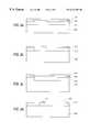
- FIG. 1 aillustrates a portion of a conventional attenuated phase shift mask 10 .
- the mask 10includes a transparent portion 12 that permits transmission of radiant energy, such as ultra violet light, and phase shifting or attenuating portions 14 that only permit transmission of about three to eight percent of the light they receive. Also, the attenuating portions 14 phase shift any light they pass by 180 degrees.
- the attenuating portions 14contain a single pattern or opening corresponding to a desired IC feature and is referred to herein as feature opening 16 (since a feature of the IC design will be produced from this opening in the attenuating portions 14 ).
- FIG. 1 bis a graph 20 illustrating the electric field amplitude, with respect to distance, present at a wafer being processed with the conventional attenuated phase shift mask 10 of FIG. 1 a .
- the electric field profileactually contains three components: the first component 22 , which is in phase with the light passing through the feature opening 16 , and the second and third components 24 , 26 , which are 180 degrees out of phase with the light passing through the feature opening 16 .
- FIG. 1 cis a graph 30 illustrating the light intensity amplitude, with respect to distance, present at a wafer being processed with the mask 10 of FIG 1 a .
- intensity of the light passing through the attenuated phase shift mask 10(FIG. 1 a ) is proportional to the electric field energy squared (i.e., I ⁇ E 2 ).
- the intensity profileincludes a first component 32 corresponding to the feature opening 16 (FIG. 1 a ). This first component 32 is desired since it corresponds to a feature of the IC design.
- the intensity profilealso includes two other components 34 , 36 which are not desired.
- These components 34 , 36are the combination (sum) of the diffraction of the 180 degrees phases of the components 24 , 26 (FIG. 1 b ) and the approximate six percent background of the attenuating portions 14 of the mask 10 (FIG. 1 a ). These components are known in the art as side lobes and may corrupt the desired feature or cause undesired features to be etched into the wafer (known in the art as side lobe effects).
- FIGS. 1 a - 1 cillustrate a simple mask 10 with only one feature opening 16 .
- the side lobe effectbecomes more pronounced as the spacing between the IC features decreases. That is, when features are designed close to each other, which is the current trend, the electric field and intensity components associated with the side lobes of each feature begin to overlap and add-up. This causes side lobes of greater amplitude and increases the side lobe effect. Sometimes, the amplitude of these “additive” side lobes is greater than the amplitude of the desired features, which further corrupts the fabrication process.
- the present inventionprovides a method of reducing side lobe printing from an attenuated phase shift mask that is less time consuming then other attempts to eliminate side lobe printing.
- the present inventionprovides a method of reducing side lobe printing using an attenuated phase shift mask that is designed to diminish the background of the attenuating portions that would otherwise be associated with a side lobe.
- the present inventionreduces the magnitude of the side lobe by placing an opaque material on the partially light transmissive material so as to reduce or prevent the background of the attenuating portion. This prevents light from passing through the partially light transmissive material and adding to the side lobe energy. By reducing this component of the side lobe energy, it is possible to keep the side lobe energy at or below the printing threshold and prevent unwanted side lobes from printing.
- FIG. 1 aillustrates a portion of a conventional attenuated phase shift mask
- FIGS. 1 b and 1 cillustrate electric field and light intensity amplitude vs. distance plots experienced at a wafer being processed with the conventional attenuated phase shift mask of FIG. 1 a;
- FIGS. 2 a - 2 dare schematic side views of an attenuated phase shift mask with opaque material added to reduce unwanted side lobes;
- FIG. 3illustrates an exemplary process for eliminating side lobe printing from attenuated phase shift masks in accordance with the present invention
- FIG. 4illustrates a verified contour map of an environment containing side lobe inhibitors according to the process illustrated in FIG. 3;
- FIGS. 5 a - 5 dillustrate exemplary simulation contour maps of different environments within an integrated (IC) design created within the process illustrated in FIG. 2;
- FIG. 6illustrates an exemplary map of an environment that has been modified to include side lobe inhibitors according to the process illustrated in FIG. 3;
- FIG. 7illustrates an exemplary map of an environment containing side lobe inhibiting opaque material in which desired IC features have undergone optimal proximity correction (OPC) in accordance with the process illustrated in FIG. 3;
- OPCoptimal proximity correction
- FIG. 8illustrates an exemplary process for simulating an environment of an IC design to obtain a contour of the features and side lobes within the environment
- FIG. 9illustrates an exemplary computer system in which the process of FIG. 3 may be implemented.
- Attenuated phase shift mask technologyis needed for processing margins at the present contact sizes of 0.15 and 0.13 ⁇ m technologies.
- the problem with the use of conventional mask (including reticle) materialis that due to transmissions in areas which are not suppose to print, there are certain pitches and combinations of contacts in which diffraction lobes superimpose and thus print (image) in the resist.
- the present inventionprovides a method of reducing side lobe printing using an attenuated phase shift mask that is designed to diminish the background light that would otherwise pass through the partially light transmissive material and be associated with a side lobe.
- the present inventionreduces the magnitude of the side lobe by placing an opaque material on the partially light transmissive material so as to reduce or prevent the background of the attenuating portion.
- the layout (design)is first determined to identify potential side lobe printing problems that would otherwise exist if only a transmissive substrate layer (also referred to as transparent material) and a partially light transmissive material were provided.
- a transparent material 200is coated with a partially light transmissive material 210 .
- the transparent materialis preferably Quartz but may be any other well-known transparent material suitable for making photomasks, including soda-lime glass, borosilicate glass, or similar natural or synthetic substances.
- the transparent materialis preferably 250 mils thick. All references to thickness herein refer to the thickness in the vertical axis when viewing a cross section and are approximate. It is expressly contemplated that varying thickness may be used and that the thickness of any material may be non-uniform.
- the partially light transmissive material 210is applied to the transparent material 200 through any well-known process such as vapor deposition or sputtering.
- the partially light transmissive material 210is preferably Molybolium Silicide (MoSi) but may also include other well known partially light transmissive materials.
- MoSiMolybolium Silicide
- the MoSiis preferably 945 angstroms thick.
- Partially light transmissive materials 210are known to transmit between two and fifteen percent of the light radiation.
- the present inventionpreferably utilizes partially transmissive materials 210 and/or thickness of the same which transmits between six and eight percent of incident light radiation.
- the transparent material 200 and partially light transmissive material 210are then coated with an opaque material 220 , such as Chromium (which may include Chrome or Chromium alloys).
- an opaque material 220such as Chromium (which may include Chrome or Chromium alloys).
- Chromiumwhich may include Chrome or Chromium alloys
- Other well known opaque materials and well-known substitutesmay be used instead of Chromium.
- the opaque materialis preferably 1000 angstroms thick.
- a resist 215is patterned by a write tool (not shown) and the resist is used to subsequently developed the reticle.
- a dry etching processis used to remove the opaque material 220 and partially light transmissive material 210 in open (exposed) areas 216 .
- a resist 216is coated on the reticle again to write opaque (chrome) side lobe inhibiting regions 221 . The resist 216 is developed and the opaque material 220 is removed in the areas where the resist 216 was exposed.
- the opaque material 220may include an opaque/partially light transmissive material that is less light transmissive that the partially light transmissive material 210 .
- the present inventiondoes not need to eliminate the background of the attenuation portion but reduce it a sufficient amount so as to reduce or prevent the background light from being transmitted through the partially light transmissive material 210 above the unwanted side lobe.
- Partially light transmissive materials 210are designed so that the light that they do pass is shifted by 180 degrees in comparison to the light passing through the transparent (e.g., transmissive) material 200 .
- the transparent (e.g., transmissive) material 200When feature openings are formed some of the light spreading outside of the transparent region defined by the PSM pattern edge destructively interferes with light passing from the partially transmissive regions. This way, the detrimental effects caused by diffraction may be controlled.
- Partially transmissive material 210can however create side lobes.
- the intensity profileincludes a first component 32 corresponding to the feature opening 16 (FIG. 1 a ).
- the intensity profilealso includes two other components 34 , 36 which are not desired. These components 34 , 36 are the combination (sum) of the diffraction of the 180 degrees phases of the components 24 , 26 (FIG. 1 b ) and the approximate six percent background of the attenuating portions 14 of the mask 10 (FIG. 1 a ).
- the present inventionreduces the magnitude of the side lobe by placing an opaque material on the partially light transmissive material to reduce or prevent light from passing through the partially light transmissive material 210 and contributing to the side lobe. By reducing one of the contributing factors to the side lobe's magnitude, the side lobe's energy may be reduced a sufficient amount so that it no longer prints. This permits integrated circuit manufacturers to continue to reduce the geometric size of the IC features.
- FIG. 3illustrates an exemplary process 100 for eliminating side lobe printing from attenuated phase shift masks.
- Process 100is also described in co-pending, commonly owned and invented U.S. Pat. application No. 08/285,696 filed Apr. 5, 1999, titled: METHOD TO ELIMINATE SIDE LOBE PRINTING OF ATTENUATED PHASE SHIFT MASK; Inventors: Baggenstoss & Stanton), the contents of which are incorporated herein by reference.
- the process 100is preferably implemented in software and executed on at least one computer system or workstation. As will become apparent, the process 100 can be executed on several computer systems or workstations to reduce the time required to execute the process 100 .
- the process 100will input a full IC chip design and simulate the various environments (i.e., placement of IC features, such as transistors) to see how the features within each environment will print from an attenuated phase shift mask created in accordance with the input design.
- the simulation of each environmentalso determines the extent and locations of unwanted side lobes that would also print based from the mask based on the input design.
- the process 100incorporates opaque material into the input design. Opaque material is placed at a side lobe location, such as directly over the side lobe, and is designed to reduce the radiant energy transmitted directly through the partially light transmissive material that would otherwise increase the magnitude of the side lobe.
- the process 100then performs an optimal proximity correction on the modified input design (only on the desired IC features) to ensure that desired features of each environment print as originally desired.
- the process 100then simulates each environment to verify that its features will print as originally desired and without side lobes. Once verified, the modified input design is used to create an attenuated phase shift mask, with side lobe reducing opaque regions, that prints the desired features. If not verified, the process 100 may be rerun to reduce or eliminate remaining side lobes.
- the process 100inputs a full IC chip design. It is desirable for the design to be contained in the industry standard GDSII format, but it should be appreciated that any other suitable format could be used.
- the designdoes not have to be created on the same computer system or workstation that is executing the process 100 .
- the designcould be created at a first computer workstation and then transferred to the computer executing the process 100 via a computer readable storage medium, network connection, electronic mail (e-mail), etc.
- the input IC designwill contain one mask level and will typically contain polygons corresponding to the numerous feature configurations. That is, it will contain a single layer of features within the full IC design, which may contain several layers, that can be printed from one attenuated phase shift mask.
- the input full IC chip designis simulated to determine how the features in the design would print from a mask created in accordance with the design.
- the hierarchy of the designis broken-up into different environments (i.e., placement of the features within the design) and then a model based simulation is performed on each environment to determine what a wafer being processed by a mask created in accordance with the input design would look like. That is, it is possible to simulate the printed contours of the features within each environment.
- These stepsare performed using a conventional behavioral model based simulation tool, such as PROTEUS by AVANT!, that is modified to identify the different environments.
- each environmentcan be distributed to another computer system or workstation executing the process 100 of the present invention and thus, multiple environments can be processed in parallel, which greatly increases the speed of the process 100 .
- the process 100can be initiated on several different computer systems or workstations using the same full IC chip design input, but once the different environments are detected at step 104 , the user can select different environments for processing by each computer system (therefore, there would not be a need to transfer an environment to a different computer workstation).
- a description of an exemplary process 600 for simulating an environment of the IC design to obtain a contour of the features and side lobes within the environmentnow follows. Initially, the original input design hierarchy is modified based on the environment of each feature (step 602 ). Each feature is then grouped with the other cells of its environment (step 604 ). At step 606 , the environment is simulated (as described below) to obtain a contour of the features within the environment. The contour represents what each feature within an environment would actually look like on the wafer being processed.
- the model based simulationmay be performed in many ways.
- a first waywould be to use an optical model.
- An optical modeluses the mathematics of image formation to produce the simulated contour pattern. Different parameters, such as the wavelength of light and numerical aperture, defocus, etc. can be set to match the settings of the exposure equipment used to process the wafer.
- a second methodwould use a process model.
- the process modelutilizes actual data from an exposed wafer, from either the resist pattern or the pattern after the wafer has been etched. This “real” data is used to create an empirical model which is adjusted so that the results of the simulation match the experimental data.
- This approachallows the software of the present invention to accurately predict the response of a given pattern without having a theoretical understanding of everything that takes place in transferring the mask pattern onto the wafer. It should be noted that the optical and process models will both be capable of generating contours for side lobes if they would be printed based on the input design and their respective simulations.
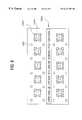
- FIGS. 5 a - 5 dillustrate exemplary simulation contour maps of four different environments 1200 , 1220 , 1240 , 1260 created during step 104 of the process (FIG. 3 ).
- the first environment 1200contains squares 1202 that represent features of the input IC design and circles 1204 that represent the contours of the features represented by the squares 1202 .
- the first environment 1200contains other contours 1206 which are not contained within a square or polygon. These other contours 1206 represent unwanted side lobes that would print within the environment 1200 from a mask based on the input IC design. All of the contours 1204 , 1206 were obtained from one of the simulation models as described above with reference to FIG. 3 . It is desirable, for the present invention to eliminate the side lobe contours 1206 yet keep the contours 1204 of the IC features 1202 .
- the second environment 1220contains squares 1222 that represent features of the input IC design and circles 1224 that represent the contours of the features represented by the squares 1222 .
- the second environment 1220contains other contours 1226 which are not contained within a square or polygon. These other contours 1226 represent unwanted side lobes that would print within the environment 1220 from a mask based on the input IC design.
- the third environment 1240contains squares 1242 that represent features of the input IC design and circles 1244 that represent the contours of the features represented by the squares 1242 .
- the third environment 1240contains other contours 1246 which are not contained within a square or polygon. These other contours 1246 represent unwanted side lobes.
- the fourth environment 1260contains squares 1262 that represent features of the input IC design and circles 264 that represent the contours of the features represented by the squares 1262 .
- the fourth environment 1260contains other contours 1266 which are not contained within a square or polygon. These other contours 1266 represent unwanted side lobes.
- All of the feature contours 1204 , 1224 , 1244 , 1264 and side lobe contours 1206 , 1226 , 1246 , 1266 within the four environments 1200 , 1220 , 1240 , 1260were obtained from one of the simulation models described above with reference to FIG. 3 (step 104 ). It is desirable, for the present invention to eliminate the side lobe contours 1206 , 1226 , 1246 , 1266 yet keep the feature contours 1204 , 1224 , 1244 , 1264 of each environment.
- the side lobe contours 1206 , 1226 , 1246 , 1266 of each environment 1200 , 1220 , 1240 , 1260differ from each other since the features of 1202 , 1222 , 1242 , 1262 of each environment 1200 , 1220 , 1240 , 1260 are placed differently. These are but a few of the many possible feature environments that could be incorporated into a single full IC chip design and a further example as to why the manual and rules based algorithm methods would be inefficient to eliminate side lobes completely. Moreover, these methods do not break down the IC chip design into environments, making it more difficult to detect and eliminate side lobes.
- the process 100continues at step 106 to determine the extent and location of any side lobes within the environments. For convenience purposes only, the remaining description will illustrate how the process 100 eliminates side lobes from printing within the third environment 1240 .
- the other environments 1200 , 1220 , 1260(FIGS. 5 a , 5 b and 5 d ) could be processed in parallel on other computer workstations if desired.
- the extent and location of side lobes within the third environment 1240is determined.
- the behavioral based simulation toolis modified to detect any contours 1246 that occur outside of the feature squares 1242 . These contours 1246 are marked as side lobes, their extent and location are recorded.
- the process 100places opaque material 1250 within the third environment at locations corresponding to the side lobe contours 1246 illustrated in FIG. 5 c to form a modified third environment 1240 a .
- the opaque material 1250is inserted into the input design and thus, form a modified input design. Since side lobes are created from light passing through the partially transmissive portions of the mask, the opaque material 1250 can reduce the radiant energy of the side lobes below the printing threshold. Therefore, the opaque material 1250 serves as a side lobe inhibitor when incorporated into the attenuated phase shift mask incorporating the modified third environment 1240 a.
- the process 100has created a modified third environment 1240 a that should print without side lobes.
- the process 100has altered the original input design of the third environment 1240 (FIG. 5 c ) and may have also altered the printing (i.e., contours) of the IC features.
- the process 100must ensure that the IC features print as originally desired.
- the process 100performs an automated correction based on the original input design (step 110 ).
- the automated correctionis performed by an optimal proximity correction (OPC) method on the modified third environment (via the modified input design) to form a corrected third environment 1240 b .
- OPCoptimal proximity correction
- one of the simulation models described above with reference to step 104is used to obtain the desired feature contours 1244 (as illustrated in FIG. 5 c ) by modifying the feature squares 1242 (FIG. 5 c ) until the desired contours 1244 of each feature is obtained. It must be noted that the side lobe inhibitors do not undergo OPC. As illustrated in FIG. 5, the corrected third environment 1240 b now contains feature polygons 1242 a (as opposed to the squares 242 illustrated in FIG. 5 c ) and auxiliary features 250 . The feature polygons 1242 a are inserted into the input design and thus, form a corrected modified input design.
- an attenuated phase shift mask implementing the corrected third environment 1240 b(via the corrected modified input design) should print the IC features as originally designed, but most importantly, should not print any side lobes. To be sure, however, the corrected third environment 1240 b is verified.
- the process 100verifies the corrected third environment by simulating the environment (as performed above with reference to step 104 ) to form a verified third environment 1240 c (step 112 ).
- the verified third environment 1240 conly contains contours 1244 a within the corrected feature polygons 1242 a .
- the contours 1244 ahave the same shape and size as the contours 1244 (FIG. 5 c ) of the original input design.
- the features of the original input designwill be printed by an attenuated phase shift mask implementing the verified corrected design of the third environment 1240 c (via the corrected modified input design). No side lobe contours are illustrated in the verified third environment 1240 c .
- step 112it is determined at step 112 that side lobes would print, the process 100 could continue at step 108 so that more auxiliary features could be incorporated into the design (and steps 108 - 112 would be repeated).
- the modified input full IC chip designis sent to a tapeout (i.e., formatted so that a mask writing tool can input the design) and then sent to a mask shop, where an attenuated phase shift mask will be created that implements the side lobe free IC chip design.
- a tapeouti.e., formatted so that a mask writing tool can input the design
- FIG. 9illustrates an exemplary computer system 650 in which the process 100 of FIG. 3 may be implemented.
- the system 650includes a central processing unit (CPU) 652 that communicates with an input/output (I/O) device 654 over a bus 670 .
- I/Oinput/output
- a second I/O device 656is illustrated, but not necessary to practice the present invention.
- the computer system 650also includes random access memory (RAM) 658 , read only memory (ROM) 660 and may include peripheral devices such as a floppy disk drive 664 or a compact disk read only memory (CD-ROM) drive 666 that also communicate with the CPU 652 over the bus 670 .
- RAMrandom access memory
- ROMread only memory
- CD-ROMcompact disk read only memory
- the exact architecture of the computer system 650is not important and that any combination of computer compatible devices may be incorporated into the system 650 as long as the process of the present invention can be executed.
- the computer system 650is a UNIX based workstation.
- the program implementing the process of the present inventionmay be stored in ROM 608 , a CD-ROM 668 , floppy disk 664 , hard disk drive or any other medium capable of storing a computer program and data required by the program.
- the computer program embodying the process of the present inventionmay be downloaded, for example, from a server computer or another computer connected to the computer system 650 .
- the process of the present inventioncan be executed in a distributed manner over several computer systems 650 , whether connected by a network or not, to process different environments of the full IC chip design in a parallel fashion.
- a computer system as shown in FIG. 9can have one or more of the devices shown therein, for example, RAM 658 , fabricated using masks formed in accordance with the present invention.
- the present inventionis capable of eliminating side lobe printing from an attenuated phase shift mask by selectively incorporating the use of opaque materials to reduce the magnitude of unwanted side lobes below the printing threshold.
- the present inventioncan handle a very large full IC chip design quickly and accurately unlike prior side lobe elimination methods.
- the present inventioncan distribute environments to other computer systems so that the environments can be processed in a parallel manner.
Landscapes
- Physics & Mathematics (AREA)
- General Physics & Mathematics (AREA)
- Preparing Plates And Mask In Photomechanical Process (AREA)
- Exposure And Positioning Against Photoresist Photosensitive Materials (AREA)
Abstract
Description
Claims (37)
Priority Applications (2)
| Application Number | Priority Date | Filing Date | Title |
|---|---|---|---|
| US09/342,229US6214497B1 (en) | 1999-06-29 | 1999-06-29 | Method to eliminate side lobe printing of attenuated phase shift masks |
| US09/619,313US6413684B1 (en) | 1999-06-29 | 2000-07-19 | Method to eliminate side lobe printing of attenuated phase shift masks |
Applications Claiming Priority (1)
| Application Number | Priority Date | Filing Date | Title |
|---|---|---|---|
| US09/342,229US6214497B1 (en) | 1999-06-29 | 1999-06-29 | Method to eliminate side lobe printing of attenuated phase shift masks |
Related Child Applications (1)
| Application Number | Title | Priority Date | Filing Date |
|---|---|---|---|
| US09/619,313DivisionUS6413684B1 (en) | 1999-06-29 | 2000-07-19 | Method to eliminate side lobe printing of attenuated phase shift masks |
Publications (1)
| Publication Number | Publication Date |
|---|---|
| US6214497B1true US6214497B1 (en) | 2001-04-10 |
Family
ID=23340919
Family Applications (2)
| Application Number | Title | Priority Date | Filing Date |
|---|---|---|---|
| US09/342,229Expired - LifetimeUS6214497B1 (en) | 1999-06-29 | 1999-06-29 | Method to eliminate side lobe printing of attenuated phase shift masks |
| US09/619,313Expired - Fee RelatedUS6413684B1 (en) | 1999-06-29 | 2000-07-19 | Method to eliminate side lobe printing of attenuated phase shift masks |
Family Applications After (1)
| Application Number | Title | Priority Date | Filing Date |
|---|---|---|---|
| US09/619,313Expired - Fee RelatedUS6413684B1 (en) | 1999-06-29 | 2000-07-19 | Method to eliminate side lobe printing of attenuated phase shift masks |
Country Status (1)
| Country | Link |
|---|---|
| US (2) | US6214497B1 (en) |
Cited By (18)
| Publication number | Priority date | Publication date | Assignee | Title |
|---|---|---|---|---|
| US6401236B1 (en)* | 1999-04-05 | 2002-06-04 | Micron Technology Inc. | Method to eliminate side lobe printing of attenuated phase shift |
| US6465160B1 (en)* | 1999-12-31 | 2002-10-15 | Winbond Electronics Corp. | Method for preventing side-lobes in photolithography |
| US20030117605A1 (en)* | 2001-12-20 | 2003-06-26 | Nanya Technology Corporation | Apparatus and method for contact hole exposure |
| US20030165750A1 (en)* | 2002-03-01 | 2003-09-04 | Hitachi, Ltd. | Method of manufacturing electronic device |
| US20030165748A1 (en)* | 2002-03-01 | 2003-09-04 | Micron Technology Inc., A Corporation Of Delaware | Pattern mask with features to minimize the effect of aberrations |
| US6680150B2 (en)* | 2001-05-25 | 2004-01-20 | Agere Systems Inc. | Suppression of side-lobe printing by shape engineering |
| US20040121242A1 (en)* | 2002-12-20 | 2004-06-24 | Stanislav Aleshin | Sidelobe correction for attenuated phase shift masks |
| EP1439420A1 (en)* | 2003-01-14 | 2004-07-21 | ASML Masktools B.V. | Simulation based method of optical proximity correction design for contact hole mask |
| US20040209170A1 (en)* | 2003-01-14 | 2004-10-21 | Broeke Douglas Van Den | Method and apparatus for providing optical proximity features to a reticle pattern for deep sub-wavelength optical lithography |
| US20040241555A1 (en)* | 2003-05-29 | 2004-12-02 | Wei-Hwa Sheu | Method of forming photoresist pattern free from side-lobe phenomenon |
| US20050053848A1 (en)* | 2003-06-30 | 2005-03-10 | Wampler Kurt E. | Method, program product and apparatus for generating assist features utilizing an image field map |
| US20050142449A1 (en)* | 2003-09-05 | 2005-06-30 | Xuelong Shi | Method and apparatus for performing model based placement of phase-balanced scattering bars for sub-wavelength optical lithography |
| US20050149900A1 (en)* | 2003-10-31 | 2005-07-07 | Thomas Laidig | Feature optimization using enhanced interference mapping lithography |
| US20060075377A1 (en)* | 2004-08-24 | 2006-04-06 | Broeke Douglas V D | Method, program product and apparatus for model based scattering bar placement for enhanced depth of focus in quarter-wavelength lithography |
| US20060083994A1 (en)* | 2004-10-20 | 2006-04-20 | Chartered Semiconductor Manufacturing , Ltd. | Method and apparatus for removing radiation side lobes |
| US20080163154A1 (en)* | 2006-12-28 | 2008-07-03 | Macronix International Co., Ltd. | Side lobe image searching method in lithography |
| US20090142704A1 (en)* | 2007-12-03 | 2009-06-04 | International Business Machines Corporation | Method for reducing side lobe printing using a barrier layer |
| EP1450206A3 (en)* | 2003-02-21 | 2012-05-30 | Canon Kabushiki Kaisha | Mask and its manufacturing method, exposure, and device fabrication method |
Families Citing this family (12)
| Publication number | Priority date | Publication date | Assignee | Title |
|---|---|---|---|---|
| US20030180629A1 (en)* | 2002-03-20 | 2003-09-25 | Nanya Technology Corporation | Masks and method for contact hole exposure |
| US6858354B1 (en)* | 2002-09-26 | 2005-02-22 | Taiwan Semiconductor Manufacturing Company | Method to prevent side lobe on seal ring |
| US7131100B2 (en)* | 2002-12-10 | 2006-10-31 | Synopsys Inc. | Identifying phantom images generated by side-lobes |
| US7276315B2 (en)* | 2003-06-27 | 2007-10-02 | Micron Technology, Inc. | Methods for generating or designing sidelobe inhibitors for radiation patterning tools |
| CN100376016C (en)* | 2003-12-16 | 2008-03-19 | 上海华虹(集团)有限公司 | A method for preventing side lobe from being transferred to substrate when etching |
| US7506299B2 (en)* | 2003-12-19 | 2009-03-17 | Asml Holding N.V. | Feature optimization using interference mapping lithography |
| US7548302B2 (en)* | 2005-03-29 | 2009-06-16 | Asml Netherlands B.V. | Lithographic apparatus and device manufacturing method |
| JP4484909B2 (en)* | 2007-07-24 | 2010-06-16 | キヤノン株式会社 | Original data creation method, original data creation method, exposure method, and original data creation program |
| JP2009053575A (en)* | 2007-08-29 | 2009-03-12 | Panasonic Corp | Photomask and pattern forming method using the same |
| JP2009058877A (en) | 2007-09-03 | 2009-03-19 | Panasonic Corp | Photomask and pattern forming method using the same |
| JP2009075207A (en)* | 2007-09-19 | 2009-04-09 | Panasonic Corp | Photomask and pattern forming method using the same |
| US9147033B2 (en)* | 2013-09-11 | 2015-09-29 | United Microelectronics Corp. | Method of making photomask layout and method of forming photomask including the photomask layout |
Citations (12)
| Publication number | Priority date | Publication date | Assignee | Title |
|---|---|---|---|---|
| US5244759A (en) | 1991-02-27 | 1993-09-14 | At&T Bell Laboratories | Single-alignment-level lithographic technique for achieving self-aligned features |
| US5582939A (en) | 1995-07-10 | 1996-12-10 | Micron Technology, Inc. | Method for fabricating and using defect-free phase shifting masks |
| US5591550A (en) | 1995-03-16 | 1997-01-07 | Lg Semicon Co., Ltd. | Phase shift mask and method for forming phase shift mask |
| US5601954A (en) | 1994-05-31 | 1997-02-11 | Advanced Micro Devices Incorporated | Attenuated phase shift mask comprising phase shifting layer with parabolically shaped sidewalls |
| US5636002A (en) | 1994-04-29 | 1997-06-03 | Lucent Technologies Inc. | Auxiliary mask features for enhancing the resolution of photolithography |
| US5672450A (en) | 1994-05-11 | 1997-09-30 | Micron Technology, Inc. | Method of phase shift mask fabrication comprising a tapered edge and phase conflict resolution |
| US5700606A (en)* | 1995-05-31 | 1997-12-23 | Sharp Kabushiki Kaisha | Photomask and a manufacturing method thereof |
| US5718829A (en) | 1995-09-01 | 1998-02-17 | Micron Technology, Inc. | Phase shift structure and method of fabrication |
| US5795682A (en) | 1996-03-08 | 1998-08-18 | Lsi Logic Corporation | Guard rings to compensate for side lobe ringing in attenuated phase shift reticles |
| US5853923A (en) | 1997-10-23 | 1998-12-29 | Taiwan Semiconductor Manufacturing Company, Ltd. | Double layer method for fabricating a rim type attenuating phase shifting mask |
| US5888674A (en)* | 1996-04-12 | 1999-03-30 | Lg Semicon Co., Ltd. | Method of manufacturing a halftone phase shift mask |
| US6057066A (en)* | 1998-04-17 | 2000-05-02 | Mitsubishi Denki Kabushiki Kaisha | Method of producing photo mask |
Family Cites Families (1)
| Publication number | Priority date | Publication date | Assignee | Title |
|---|---|---|---|---|
| JP3934719B2 (en)* | 1995-12-22 | 2007-06-20 | 株式会社東芝 | Optical proximity correction method |
- 1999
- 1999-06-29USUS09/342,229patent/US6214497B1/ennot_activeExpired - Lifetime
- 2000
- 2000-07-19USUS09/619,313patent/US6413684B1/ennot_activeExpired - Fee Related
Patent Citations (12)
| Publication number | Priority date | Publication date | Assignee | Title |
|---|---|---|---|---|
| US5244759A (en) | 1991-02-27 | 1993-09-14 | At&T Bell Laboratories | Single-alignment-level lithographic technique for achieving self-aligned features |
| US5636002A (en) | 1994-04-29 | 1997-06-03 | Lucent Technologies Inc. | Auxiliary mask features for enhancing the resolution of photolithography |
| US5672450A (en) | 1994-05-11 | 1997-09-30 | Micron Technology, Inc. | Method of phase shift mask fabrication comprising a tapered edge and phase conflict resolution |
| US5601954A (en) | 1994-05-31 | 1997-02-11 | Advanced Micro Devices Incorporated | Attenuated phase shift mask comprising phase shifting layer with parabolically shaped sidewalls |
| US5591550A (en) | 1995-03-16 | 1997-01-07 | Lg Semicon Co., Ltd. | Phase shift mask and method for forming phase shift mask |
| US5700606A (en)* | 1995-05-31 | 1997-12-23 | Sharp Kabushiki Kaisha | Photomask and a manufacturing method thereof |
| US5582939A (en) | 1995-07-10 | 1996-12-10 | Micron Technology, Inc. | Method for fabricating and using defect-free phase shifting masks |
| US5718829A (en) | 1995-09-01 | 1998-02-17 | Micron Technology, Inc. | Phase shift structure and method of fabrication |
| US5795682A (en) | 1996-03-08 | 1998-08-18 | Lsi Logic Corporation | Guard rings to compensate for side lobe ringing in attenuated phase shift reticles |
| US5888674A (en)* | 1996-04-12 | 1999-03-30 | Lg Semicon Co., Ltd. | Method of manufacturing a halftone phase shift mask |
| US5853923A (en) | 1997-10-23 | 1998-12-29 | Taiwan Semiconductor Manufacturing Company, Ltd. | Double layer method for fabricating a rim type attenuating phase shifting mask |
| US6057066A (en)* | 1998-04-17 | 2000-05-02 | Mitsubishi Denki Kabushiki Kaisha | Method of producing photo mask |
Cited By (40)
| Publication number | Priority date | Publication date | Assignee | Title |
|---|---|---|---|---|
| US6401236B1 (en)* | 1999-04-05 | 2002-06-04 | Micron Technology Inc. | Method to eliminate side lobe printing of attenuated phase shift |
| US6465160B1 (en)* | 1999-12-31 | 2002-10-15 | Winbond Electronics Corp. | Method for preventing side-lobes in photolithography |
| US6680150B2 (en)* | 2001-05-25 | 2004-01-20 | Agere Systems Inc. | Suppression of side-lobe printing by shape engineering |
| US20030117605A1 (en)* | 2001-12-20 | 2003-06-26 | Nanya Technology Corporation | Apparatus and method for contact hole exposure |
| US7105278B2 (en) | 2002-03-01 | 2006-09-12 | Micron Technology, Inc. | Pattern mask with features to minimize the effect of aberrations |
| US20030165748A1 (en)* | 2002-03-01 | 2003-09-04 | Micron Technology Inc., A Corporation Of Delaware | Pattern mask with features to minimize the effect of aberrations |
| CN1320601C (en)* | 2002-03-01 | 2007-06-06 | 株式会社日立制作所 | Manufacturing method of electron device |
| US6803157B2 (en) | 2002-03-01 | 2004-10-12 | Micron Technology, Inc. | Pattern mask with features to minimize the effect of aberrations |
| US20030165750A1 (en)* | 2002-03-01 | 2003-09-04 | Hitachi, Ltd. | Method of manufacturing electronic device |
| US20060093927A1 (en)* | 2002-03-01 | 2006-05-04 | Pary Baluswamy | Pattern mask with features to minimize the effect of aberrations |
| US20050003281A1 (en)* | 2002-03-01 | 2005-01-06 | Micron Technology, Inc. A Corporation Of Delaware | Pattern mask with features to minimize the effect of aberrations |
| US6979525B2 (en)* | 2002-03-01 | 2005-12-27 | Renesas Technology Corp. | Method of manufacturing electronic device |
| US20040121242A1 (en)* | 2002-12-20 | 2004-06-24 | Stanislav Aleshin | Sidelobe correction for attenuated phase shift masks |
| US6911285B2 (en)* | 2002-12-20 | 2005-06-28 | Lsi Logic Corporation | Sidelobe correction for attenuated phase shift masks |
| US20040229133A1 (en)* | 2003-01-14 | 2004-11-18 | Socha Robert John | Method of optical proximity correction design for contact hole mask |
| SG139530A1 (en)* | 2003-01-14 | 2008-02-29 | Asml Masktools Bv | Method of optical proximity correction design for contact hole mask |
| US7774736B2 (en) | 2003-01-14 | 2010-08-10 | Asml Masktools B.V. | Method and apparatus for providing optical proximity features to a reticle pattern for deep sub-wavelength optical lithography |
| US7594199B2 (en) | 2003-01-14 | 2009-09-22 | Asml Masktools B.V. | Method of optical proximity correction design for contact hole mask |
| US7247574B2 (en) | 2003-01-14 | 2007-07-24 | Asml Masktools B.V. | Method and apparatus for providing optical proximity features to a reticle pattern for deep sub-wavelength optical lithography |
| US20070162889A1 (en)* | 2003-01-14 | 2007-07-12 | Asml Masktools B.V. | Method and apparatus for providing optical proximity features to a reticle pattern for deep sub-wavelength optical lithography |
| EP1439420A1 (en)* | 2003-01-14 | 2004-07-21 | ASML Masktools B.V. | Simulation based method of optical proximity correction design for contact hole mask |
| US20040209170A1 (en)* | 2003-01-14 | 2004-10-21 | Broeke Douglas Van Den | Method and apparatus for providing optical proximity features to a reticle pattern for deep sub-wavelength optical lithography |
| EP1450206A3 (en)* | 2003-02-21 | 2012-05-30 | Canon Kabushiki Kaisha | Mask and its manufacturing method, exposure, and device fabrication method |
| US20040241555A1 (en)* | 2003-05-29 | 2004-12-02 | Wei-Hwa Sheu | Method of forming photoresist pattern free from side-lobe phenomenon |
| US7189495B2 (en)* | 2003-05-29 | 2007-03-13 | Macronix International Co., Ltd. | Method of forming photoresist pattern free from side-lobe phenomenon |
| US7376930B2 (en) | 2003-06-30 | 2008-05-20 | Asml Masktools B.V. | Method, program product and apparatus for generating assist features utilizing an image field map |
| US20050053848A1 (en)* | 2003-06-30 | 2005-03-10 | Wampler Kurt E. | Method, program product and apparatus for generating assist features utilizing an image field map |
| US7550235B2 (en) | 2003-09-05 | 2009-06-23 | Asml Masktools B.V. | Method and apparatus for performing model based placement of phase-balanced scattering bars for sub-wavelength optical lithography |
| US20050142449A1 (en)* | 2003-09-05 | 2005-06-30 | Xuelong Shi | Method and apparatus for performing model based placement of phase-balanced scattering bars for sub-wavelength optical lithography |
| US7231629B2 (en) | 2003-10-31 | 2007-06-12 | Asml Masktools B.V. | Feature optimization using enhanced interference mapping lithography |
| US20050149900A1 (en)* | 2003-10-31 | 2005-07-07 | Thomas Laidig | Feature optimization using enhanced interference mapping lithography |
| US8495529B2 (en) | 2004-08-24 | 2013-07-23 | Asml Masktools B.V. | Method, program product and apparatus for model based scattering bar placement for enhanced depth of focus in quarter-wavelength lithography |
| US20060075377A1 (en)* | 2004-08-24 | 2006-04-06 | Broeke Douglas V D | Method, program product and apparatus for model based scattering bar placement for enhanced depth of focus in quarter-wavelength lithography |
| US7620930B2 (en) | 2004-08-24 | 2009-11-17 | Asml Masktools B.V. | Method, program product and apparatus for model based scattering bar placement for enhanced depth of focus in quarter-wavelength lithography |
| US8048588B2 (en)* | 2004-10-20 | 2011-11-01 | Globalfoundries Singapore Pte. Ltd. | Method and apparatus for removing radiation side lobes |
| US20060083994A1 (en)* | 2004-10-20 | 2006-04-20 | Chartered Semiconductor Manufacturing , Ltd. | Method and apparatus for removing radiation side lobes |
| US7721247B2 (en)* | 2006-12-28 | 2010-05-18 | Macronix International Co., Ltd. | Side lobe image searching method in lithography |
| US20080163154A1 (en)* | 2006-12-28 | 2008-07-03 | Macronix International Co., Ltd. | Side lobe image searching method in lithography |
| US20090142704A1 (en)* | 2007-12-03 | 2009-06-04 | International Business Machines Corporation | Method for reducing side lobe printing using a barrier layer |
| US8268542B2 (en) | 2007-12-03 | 2012-09-18 | International Business Machines Corporation | Method for reducing side lobe printing using a barrier layer |
Also Published As
| Publication number | Publication date |
|---|---|
| US6413684B1 (en) | 2002-07-02 |
Similar Documents
| Publication | Publication Date | Title |
|---|---|---|
| US6214497B1 (en) | Method to eliminate side lobe printing of attenuated phase shift masks | |
| US6238824B1 (en) | Method for designing and making photolithographic reticle, reticle, and photolithographic process | |
| US7172838B2 (en) | Chromeless phase mask layout generation | |
| US6185727B1 (en) | Design verification for asymmetric phase shift mask layouts | |
| US8732625B2 (en) | Methods for performing model-based lithography guided layout design | |
| US8037429B2 (en) | Model-based SRAF insertion | |
| US8102408B2 (en) | Computer-implemented methods and systems for determining different process windows for a wafer printing process for different reticle designs | |
| US5801954A (en) | Process for designing and checking a mask layout | |
| US20060161452A1 (en) | Computer-implemented methods, processors, and systems for creating a wafer fabrication process | |
| US9418195B2 (en) | Layout content analysis for source mask optimization acceleration | |
| US6465138B1 (en) | Method for designing and making photolithographic reticle, reticle, and photolithographic process | |
| US9779186B2 (en) | Methods for performing model-based lithography guided layout design | |
| US8122388B2 (en) | Phase-shifting masks with sub-wavelength diffractive optical elements | |
| US20050283747A1 (en) | OPC simulation model using SOCS decomposition of edge fragments | |
| US6401236B1 (en) | Method to eliminate side lobe printing of attenuated phase shift | |
| US8595655B2 (en) | Method and system for lithographic simulation and verification | |
| Schellenberg et al. | Adoption of OPC and the Impact on Design and Layout | |
| US7131100B2 (en) | Identifying phantom images generated by side-lobes | |
| US7539954B2 (en) | OPC simulation model using SOCS decomposition of edge fragments | |
| CN101006329A (en) | Embedded attenuated phase shift mask with tunable transmission | |
| Liebmann et al. | Alternating phase-shifted mask for logic gate levels, design, and mask manufacturing | |
| US7611806B2 (en) | Sub-wavelength diffractive elements to reduce corner rounding | |
| US6844118B2 (en) | Method and layout for high density reticle | |
| US20060051680A1 (en) | Combining image imbalance compensation and optical proximity correction in designing phase shift masks | |
| WO2025048779A1 (en) | Three-dimensional photomask transmission with kernel-based modeling |
Legal Events
| Date | Code | Title | Description |
|---|---|---|---|
| AS | Assignment | Owner name:MICRON TECHNOLOGY, INC., IDAHO Free format text:ASSIGNMENT OF ASSIGNORS INTEREST;ASSIGNOR:STANTON, WILLIAM;REEL/FRAME:010077/0300 Effective date:19990616 | |
| STCF | Information on status: patent grant | Free format text:PATENTED CASE | |
| CC | Certificate of correction | ||
| FPAY | Fee payment | Year of fee payment:4 | |
| FEPP | Fee payment procedure | Free format text:PAYOR NUMBER ASSIGNED (ORIGINAL EVENT CODE: ASPN); ENTITY STATUS OF PATENT OWNER: LARGE ENTITY Free format text:PAYER NUMBER DE-ASSIGNED (ORIGINAL EVENT CODE: RMPN); ENTITY STATUS OF PATENT OWNER: LARGE ENTITY | |
| FPAY | Fee payment | Year of fee payment:8 | |
| FPAY | Fee payment | Year of fee payment:12 | |
| AS | Assignment | Owner name:U.S. BANK NATIONAL ASSOCIATION, AS COLLATERAL AGENT, CALIFORNIA Free format text:SECURITY INTEREST;ASSIGNOR:MICRON TECHNOLOGY, INC.;REEL/FRAME:038669/0001 Effective date:20160426 Owner name:U.S. BANK NATIONAL ASSOCIATION, AS COLLATERAL AGEN Free format text:SECURITY INTEREST;ASSIGNOR:MICRON TECHNOLOGY, INC.;REEL/FRAME:038669/0001 Effective date:20160426 | |
| AS | Assignment | Owner name:MORGAN STANLEY SENIOR FUNDING, INC., AS COLLATERAL AGENT, MARYLAND Free format text:PATENT SECURITY AGREEMENT;ASSIGNOR:MICRON TECHNOLOGY, INC.;REEL/FRAME:038954/0001 Effective date:20160426 Owner name:MORGAN STANLEY SENIOR FUNDING, INC., AS COLLATERAL Free format text:PATENT SECURITY AGREEMENT;ASSIGNOR:MICRON TECHNOLOGY, INC.;REEL/FRAME:038954/0001 Effective date:20160426 | |
| AS | Assignment | Owner name:U.S. BANK NATIONAL ASSOCIATION, AS COLLATERAL AGENT, CALIFORNIA Free format text:CORRECTIVE ASSIGNMENT TO CORRECT THE REPLACE ERRONEOUSLY FILED PATENT #7358718 WITH THE CORRECT PATENT #7358178 PREVIOUSLY RECORDED ON REEL 038669 FRAME 0001. ASSIGNOR(S) HEREBY CONFIRMS THE SECURITY INTEREST;ASSIGNOR:MICRON TECHNOLOGY, INC.;REEL/FRAME:043079/0001 Effective date:20160426 Owner name:U.S. BANK NATIONAL ASSOCIATION, AS COLLATERAL AGEN Free format text:CORRECTIVE ASSIGNMENT TO CORRECT THE REPLACE ERRONEOUSLY FILED PATENT #7358718 WITH THE CORRECT PATENT #7358178 PREVIOUSLY RECORDED ON REEL 038669 FRAME 0001. ASSIGNOR(S) HEREBY CONFIRMS THE SECURITY INTEREST;ASSIGNOR:MICRON TECHNOLOGY, INC.;REEL/FRAME:043079/0001 Effective date:20160426 | |
| AS | Assignment | Owner name:JPMORGAN CHASE BANK, N.A., AS COLLATERAL AGENT, ILLINOIS Free format text:SECURITY INTEREST;ASSIGNORS:MICRON TECHNOLOGY, INC.;MICRON SEMICONDUCTOR PRODUCTS, INC.;REEL/FRAME:047540/0001 Effective date:20180703 Owner name:JPMORGAN CHASE BANK, N.A., AS COLLATERAL AGENT, IL Free format text:SECURITY INTEREST;ASSIGNORS:MICRON TECHNOLOGY, INC.;MICRON SEMICONDUCTOR PRODUCTS, INC.;REEL/FRAME:047540/0001 Effective date:20180703 | |
| AS | Assignment | Owner name:MICRON TECHNOLOGY, INC., IDAHO Free format text:RELEASE BY SECURED PARTY;ASSIGNOR:U.S. BANK NATIONAL ASSOCIATION, AS COLLATERAL AGENT;REEL/FRAME:047243/0001 Effective date:20180629 | |
| AS | Assignment | Owner name:MICRON TECHNOLOGY, INC., IDAHO Free format text:RELEASE BY SECURED PARTY;ASSIGNOR:MORGAN STANLEY SENIOR FUNDING, INC., AS COLLATERAL AGENT;REEL/FRAME:050937/0001 Effective date:20190731 | |
| AS | Assignment | Owner name:MICRON TECHNOLOGY, INC., IDAHO Free format text:RELEASE BY SECURED PARTY;ASSIGNOR:JPMORGAN CHASE BANK, N.A., AS COLLATERAL AGENT;REEL/FRAME:051028/0001 Effective date:20190731 Owner name:MICRON SEMICONDUCTOR PRODUCTS, INC., IDAHO Free format text:RELEASE BY SECURED PARTY;ASSIGNOR:JPMORGAN CHASE BANK, N.A., AS COLLATERAL AGENT;REEL/FRAME:051028/0001 Effective date:20190731 |