US6213979B1 - Medical line anchoring system - Google Patents
Medical line anchoring systemDownload PDFInfo
- Publication number
- US6213979B1 US6213979B1US08/865,231US86523197AUS6213979B1US 6213979 B1US6213979 B1US 6213979B1US 86523197 AUS86523197 AUS 86523197AUS 6213979 B1US6213979 B1US 6213979B1
- Authority
- US
- United States
- Prior art keywords
- cover
- base
- anchoring system
- retainer
- post
- Prior art date
- Legal status (The legal status is an assumption and is not a legal conclusion. Google has not performed a legal analysis and makes no representation as to the accuracy of the status listed.)
- Expired - Lifetime
Links
- 238000004873anchoringMethods0.000titleclaimsabstractdescription116
- 230000007246mechanismEffects0.000claimsabstractdescription42
- 239000000853adhesiveSubstances0.000claimsabstractdescription18
- 230000001070adhesive effectEffects0.000claimsabstractdescription17
- 239000012790adhesive layerSubstances0.000claimsdescription15
- 230000014759maintenance of locationEffects0.000claimsdescription12
- 238000010276constructionMethods0.000claims1
- 238000005452bendingMethods0.000abstract1
- 239000000463materialSubstances0.000description23
- 230000036541healthEffects0.000description20
- 239000010410layerSubstances0.000description8
- -1polyethylenePolymers0.000description8
- 239000012530fluidSubstances0.000description7
- 210000001624hipAnatomy0.000description7
- 238000004891communicationMethods0.000description6
- 239000006260foamSubstances0.000description6
- 238000001990intravenous administrationMethods0.000description6
- 239000012528membraneSubstances0.000description6
- 238000000034methodMethods0.000description6
- 230000000717retained effectEffects0.000description6
- 230000000994depressogenic effectEffects0.000description5
- 238000003780insertionMethods0.000description5
- 230000037431insertionEffects0.000description5
- 239000004698PolyethyleneSubstances0.000description4
- 239000004033plasticSubstances0.000description4
- 229920003023plasticPolymers0.000description4
- 229920000573polyethylenePolymers0.000description4
- 239000004743PolypropyleneSubstances0.000description3
- 239000011796hollow space materialSubstances0.000description3
- 238000002347injectionMethods0.000description3
- 239000007924injectionSubstances0.000description3
- 230000003993interactionEffects0.000description3
- 239000004816latexSubstances0.000description3
- 229920000126latexPolymers0.000description3
- 229920001155polypropylenePolymers0.000description3
- 210000003462veinAnatomy0.000description3
- 229920001651CyanoacrylatePolymers0.000description2
- LFQSCWFLJHTTHZ-UHFFFAOYSA-NEthanolChemical compoundCCOLFQSCWFLJHTTHZ-UHFFFAOYSA-N0.000description2
- MWCLLHOVUTZFKS-UHFFFAOYSA-NMethyl cyanoacrylateChemical compoundCOC(=O)C(=C)C#NMWCLLHOVUTZFKS-UHFFFAOYSA-N0.000description2
- 208000012266Needlestick injuryDiseases0.000description2
- 229920002678cellulosePolymers0.000description2
- 239000001913celluloseSubstances0.000description2
- 230000008878couplingEffects0.000description2
- 238000010168coupling processMethods0.000description2
- 238000005859coupling reactionMethods0.000description2
- 229940079593drugDrugs0.000description2
- 239000003814drugSubstances0.000description2
- 238000001631haemodialysisMethods0.000description2
- 230000000322hemodialysisEffects0.000description2
- 238000007373indentationMethods0.000description2
- 208000015181infectious diseaseDiseases0.000description2
- 230000002401inhibitory effectEffects0.000description2
- 238000004519manufacturing processMethods0.000description2
- 238000012986modificationMethods0.000description2
- 230000004048modificationEffects0.000description2
- 229920000642polymerPolymers0.000description2
- 235000001674Agaricus brunnescensNutrition0.000description1
- 206010069803Injury associated with deviceDiseases0.000description1
- 206010052428WoundDiseases0.000description1
- 208000027418Wounds and injuryDiseases0.000description1
- 230000003466anti-cipated effectEffects0.000description1
- 229940030602cardiac therapy drugDrugs0.000description1
- 230000008859changeEffects0.000description1
- 230000001010compromised effectEffects0.000description1
- 230000036461convulsionEffects0.000description1
- 230000003247decreasing effectEffects0.000description1
- 238000013461designMethods0.000description1
- 239000004744fabricSubstances0.000description1
- 238000001802infusionMethods0.000description1
- 238000001746injection mouldingMethods0.000description1
- 238000009434installationMethods0.000description1
- 230000007774longtermEffects0.000description1
- 238000002483medicationMethods0.000description1
- 238000005065miningMethods0.000description1
- 230000036961partial effectEffects0.000description1
- 230000037361pathwayEffects0.000description1
- 230000002093peripheral effectEffects0.000description1
- 239000004417polycarbonateSubstances0.000description1
- 229920000515polycarbonatePolymers0.000description1
- 239000002861polymer materialSubstances0.000description1
- 238000003825pressingMethods0.000description1
- 230000004044responseEffects0.000description1
- 230000000284resting effectEffects0.000description1
- 230000037390scarringEffects0.000description1
- 238000007789sealingMethods0.000description1
- 239000003566sealing materialSubstances0.000description1
- 239000007787solidSubstances0.000description1
- 239000002904solventSubstances0.000description1
- 238000007460surgical drainageMethods0.000description1
- 239000003356suture materialSubstances0.000description1
Images


Classifications
- A—HUMAN NECESSITIES
- A61—MEDICAL OR VETERINARY SCIENCE; HYGIENE
- A61M—DEVICES FOR INTRODUCING MEDIA INTO, OR ONTO, THE BODY; DEVICES FOR TRANSDUCING BODY MEDIA OR FOR TAKING MEDIA FROM THE BODY; DEVICES FOR PRODUCING OR ENDING SLEEP OR STUPOR
- A61M25/00—Catheters; Hollow probes
- A61M25/01—Introducing, guiding, advancing, emplacing or holding catheters
- A61M25/02—Holding devices, e.g. on the body
- A61M2025/024—Holding devices, e.g. on the body having a clip or clamp system
- A—HUMAN NECESSITIES
- A61—MEDICAL OR VETERINARY SCIENCE; HYGIENE
- A61M—DEVICES FOR INTRODUCING MEDIA INTO, OR ONTO, THE BODY; DEVICES FOR TRANSDUCING BODY MEDIA OR FOR TAKING MEDIA FROM THE BODY; DEVICES FOR PRODUCING OR ENDING SLEEP OR STUPOR
- A61M25/00—Catheters; Hollow probes
- A61M25/01—Introducing, guiding, advancing, emplacing or holding catheters
- A61M25/02—Holding devices, e.g. on the body
- A61M2025/0246—Holding devices, e.g. on the body fixed on the skin having a cover for covering the holding means
- A—HUMAN NECESSITIES
- A61—MEDICAL OR VETERINARY SCIENCE; HYGIENE
- A61M—DEVICES FOR INTRODUCING MEDIA INTO, OR ONTO, THE BODY; DEVICES FOR TRANSDUCING BODY MEDIA OR FOR TAKING MEDIA FROM THE BODY; DEVICES FOR PRODUCING OR ENDING SLEEP OR STUPOR
- A61M25/00—Catheters; Hollow probes
- A61M25/01—Introducing, guiding, advancing, emplacing or holding catheters
- A61M25/02—Holding devices, e.g. on the body
- A61M2025/0253—Holding devices, e.g. on the body where the catheter is attached by straps, bands or the like secured by adhesives
- A61M2025/026—Holding devices, e.g. on the body where the catheter is attached by straps, bands or the like secured by adhesives where the straps are releasably secured, e.g. by hook and loop-type fastening devices
- A—HUMAN NECESSITIES
- A61—MEDICAL OR VETERINARY SCIENCE; HYGIENE
- A61M—DEVICES FOR INTRODUCING MEDIA INTO, OR ONTO, THE BODY; DEVICES FOR TRANSDUCING BODY MEDIA OR FOR TAKING MEDIA FROM THE BODY; DEVICES FOR PRODUCING OR ENDING SLEEP OR STUPOR
- A61M25/00—Catheters; Hollow probes
- A61M25/01—Introducing, guiding, advancing, emplacing or holding catheters
- A61M25/02—Holding devices, e.g. on the body
- A61M2025/0266—Holding devices, e.g. on the body using pads, patches, tapes or the like
- Y—GENERAL TAGGING OF NEW TECHNOLOGICAL DEVELOPMENTS; GENERAL TAGGING OF CROSS-SECTIONAL TECHNOLOGIES SPANNING OVER SEVERAL SECTIONS OF THE IPC; TECHNICAL SUBJECTS COVERED BY FORMER USPC CROSS-REFERENCE ART COLLECTIONS [XRACs] AND DIGESTS
- Y10—TECHNICAL SUBJECTS COVERED BY FORMER USPC
- Y10S—TECHNICAL SUBJECTS COVERED BY FORMER USPC CROSS-REFERENCE ART COLLECTIONS [XRACs] AND DIGESTS
- Y10S128/00—Surgery
- Y10S128/26—Cannula supporters
Definitions
- the present inventionrelates to anchoring systems for anchoring medical lines to patients.
- IV cathetersintravenous catheters
- CVCcentral venous catheter
- PICCperipherally inserted central catheter
- the catheterIn these cases, long-term IV infusion typically requires that the catheter remain in place for many days.
- the catheterIn order to secure such an IV catheter in position at the insertion site, the catheter often is provided with an integrated or a movable flexible clamp with winged extensions which are sutured to the patient's skin.
- the flexible clampIn other applications, the flexible clamp is covered by a rigid box clamp, which receives the catheter/clamp combination in a friction-fit manner.
- the rigid box clamp and the flexible clamphave lateral, aligned holes in them, which allow the combination to be sutured to the patient's skin.
- the present inventionthus involves an anchoring system for securing a medical line to the body of a patient.
- the systemcomprises a retainer including a base that defines a receiving area for receiving a portion of the medical line.
- a coveris permanently coupled to the base. The cover is movable between a closed position, in which at least a portion of the cover extends over at least a portion of the receiving area, and an open position, in which the receiving area is at least partially open.
- a latching mechanismoperates between the base and the cover to releasably latch the cover to the base with the cover in the closed position.
- Interacting structureis located generally beneath the cover with the cover in the closed position. The interacting structure is adapted to limit movement of the medical line through to the retainer when the catheter is placed within the receiving area.
- the present inventioninvolves an anchoring system for securing a medical line to the body of a patient.
- the systemincludes a fitting adapted to engage with the medical line and having at least one opening.
- a retainercomprises a base including a platform and at least one post extending from the platform and arranged to interact with the hole of the fitting.
- a coveris movably coupled to the base so as to be moved between an open position and a closed position.
- a latching mechanismoperates between the cover and the base to releasably latch the cover to the base in the closed position.
- an anchoring systemfor securing a medical line to the body of a patient.
- the anchoring systemcomprises an adaptor having an adaptor body with a longitudinal axis defined between first and second ends.
- a first connectoris located at the first end of the adaptor for connection to a first medical line
- a second connectoris located at the second end for connection to a second medical line.
- a retainerincludes a base and a cover permanently coupled to the base. The cover is movable between an open position and a closed position.
- a latching mechanismreleasably latches the cover to the base in the closed position.
- a channel iaarranged to lie between the base and the cover in the closed position.
- the channelis shaped to retain the adaptor between the cover and the base with the cover in the closed position to inhibit movement of the adapter in a direction generally parallel to the adapter's longitudinal axis.
- An adhesive layeris attached to the retainer and is adapted to adhesively secure the retainer to the body of a patient.
- a preferred method of anchoring a medical line to a patientinvolves providing a retainer including a base having a plurality of posts, and a cover attached to the base by a flexible leash.
- the provided coveralso includes a corresponding plurality of openings with each opening comprising a slot.
- the retaineris coupled to an adhesive layer.
- the anchoring systemis positioned on the body of the patient, and the adhesive layer is attached to the body of the patient.
- a medical deviceis arranged between the posts of the base.
- the coveris positioned over the base to bring the openings of the cover in proximity with the posts of the base.
- the coveris shifted relative to the base to engage the posts with the slots of the openings.
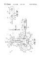
- FIG. 1Ais a perspective view of an anchoring system in accordance with a preferred embodiment of the present invention and illustrates a retainer of the anchoring system in an open position together with an exemplary catheter wing clamp fitting (the components of which are illustrated as exploded above the retainer);
- FIG. 1Bis a bottom plan view of a cover of the retainer of FIG. 1A;
- FIG. 2is a perspective view of the anchoring system of FIG. 1A with the cover of the retainer shown in a partially closed position;
- FIG. 3is a cross-sectional view of the anchoring system of FIG. 2, with the retainer shown in a completely closed position and the catheter wing clamp fitting assembled and anchored therein;
- FIG. 4Ais a perspective view of a retainer in accordance with another preferred embodiment of the present invention, shown in an open position;
- FIG. 4Bis a bottom plan view of a cover portion of the retainer of FIG. 4A;
- FIG. 5is a perspective view of the retainer of FIG. 4A, shown in a partially closed position
- FIG. 6is a perspective view of a retainer in accordance with another preferred embodiment of the present invention, shown in an open position;
- FIG. 7is a perspective view of the retainer of FIG. 6, shown in a closed position
- FIG. 8is a cross-sectional view of the retainer of FIG. 7, taken along the line 8 — 8 ;
- FIG. 9is a cross-sectional view of the retainer according to FIG. 8, but with a tang shown in a release position;
- FIG. 10Ais a prospective view of an anchoring system in accordance with an additional preferred embodiment of the present invention and illustrates a retainer of the anchoring system in an open position and together with an exemplary catheter adaptor;
- FIG. 10Bis a bottom plan view of a cover portion of the retainer of FIG. 10A;
- FIG. 11is a prospective view of the retainer of FIG. 10A, shown in a partially closed position with the cover interacting with the catheter adapter;
- FIG. 12is a cross-sectional view of the retainer according to FIG. 11, shown in a completely closed position, with the catheter adaptor anchored therein.
- the present embodiments of the medical line anchoring systemare disclosed in the context of an exemplary central line catheter.
- the principles of the present inventionare not limited to PICCs or CVCs.
- the anchoring systems and retainers disclosed hereinalso can be successfully utilized in connection with other types of medical lines, including tubes for fluid communication and electrical wires.
- the retainers disclosed hereincan retain CVCs, PICCs, Foley catheters, and hemodialysis catheters, surgical drainage tubes, feeding tubes, chest tubes, nasogastric tubes, scopes, as well as with electrical wires or cables connected to external or implanted electronic devices or sensors.
- the illustration and description of the anchoring system 8 in connection with a catheteris mainly exemplary of one possible application of the system.
- the anchoring systemsalso all include interacting structure that operates between a retainer of the anchoring system and a fitting which in some applications is releasably attached to the medical line and in other applications is integrally formed with the medical line.
- the interacting structure between the retainer and the fittinggenerally inhibits relative movement between the medical line and the anchoring system in at least one degree of freedom.
- a longitudinal axisis generally parallel to a section of the medical line to be retained by the anchoring system, generally in the plane of a retainer base (discussed below).
- a lateral axisis generally perpendicular to the longitudinal axis within the plane of the base.
- a transverse axisextends transverse to both the longitudinal and lateral axes.
- the “longitudinal direction”refers to a direction substantially parallel to the longitudinal axis.
- the lateral directionrefers to a direction substantially parallel to the lateral axis.
- the transverse directionrefer to a direction substantially parallel to the transverse axis.
- FIGS. 1 to 3illustrate an anchoring system 8 constructed in accordance with a preferred embodiment of the present invention.
- the system 8includes a retainer 10 which is configured to retain a catheter, either directly or by way of a fitting 11 .
- the fitting 11comprises a catheter box clamp 12 and a soft wing clamp 13 for use with a central line catheter 15 .
- the retainer 10includes a base 14 .
- the base 14 of the retainer 10is attached to an anchor pad 16 , which forms a part of the anchoring system 8 .
- the base 14desirably is secured to the anchor pad 16 by a solvent bond adhesive, such as cyanoacrylate or other bonding material.
- a solvent bond adhesivesuch as cyanoacrylate or other bonding material.
- One such adhesiveis available commercially as Part No. 4693 from the Minnesota Mining and Manufacturing Company (3M).
- the anchor pad 16comprises a flexible structural layer for securing the retainer 10 to a patient's skin.
- the paddesirably comprises a laminate structure with an upper cellulose foam layer (e.g., closed-cell polyethylene foam), and a bottom adhesive layer.
- the adhesivedesirably is a medical-grade adhesive and can be either diaphoretic or nondiaphoretic, depending upon the particular application. Such foam with an adhesive layer is available commercially from New Dimensions in Medicine of Columbus, Ohio.
- the retainer and/or anchor padcan include suture holes in addition to the adhesive layer to further secure the anchor pad to the patient's skin.
- an upper surface of the foam layeris roughened by corona-treating the foam with a low electric charge.
- the roughened or porous upper surface of the anchor pad 16improves the quality of the adhesive joint formed by the cyanoacrylate (or by another type of adhesive or bonding material) between the base 14 to the anchor pad 16 .
- the flexible anchor pad 16can comprise a medical-grade adhesive bottom layer, an inner cellulose foam layer and an upper paper or other woven or nonwoven cloth layer.
- a removable paper or plastic backing 17desirably covers the bottom adhesive surface before use.
- the backing 17preferably resists tearing and is divided into a plurality of pieces to ease attachment of the pad to a patient's skin.
- the backing 17is split along a center line 18 of the flexible anchor pad 16 in order to expose only half of the adhesive bottom surface at one time.
- the backing 17also advantageously extends beyond at least one edge of the anchor pad 16 , as illustrated, to facilitate removal of the backing 17 from the adhesive layer.
- the anchor pad 16also desirably includes a pair of opposing concave sections that narrows the center of the anchor pad proximate to the base 14 .
- the peripheral ends of the anchor pad 16have more contact area to provide greater stability and adhesion to a patient's skin, while allowing the retainer 10 , which is located at center section of the anchor pad 16 , to be placed adjacent to an insertion site of the catheter 15 .
- anchor pad 16has not been shown in the other drawings that illustrates this embodiment, nor in some of the drawings illustrating the other embodiments, it will be understood that a similar flexible anchor pad is included to secure the retainer to the patent's skin with each embodiment.
- the base 14 and the catheter 15desirably include interacting structure to couple the catheter 15 to the base 14 .
- the interacting structuremounts the medical line either directly or by way of a fitting (e.g., the box clamp 12 and soft wing clamp 13 ) to the base 14 .
- a fittinge.g., the box clamp 12 and soft wing clamp 13
- a portion of the interacting structure desirableis formed on the fitting and another portion of the interacting structure is formed on the retainer.
- the term “mount,” when used with reference to the relation between the catheter or fitting and the retainer,does not necessarily imply that the catheter 15 or fitting 11 are immobilized or fixed.
- this termis meant to describe the condition in which the interacting structure inhibits movement of the catheter 15 relative to the retainer 10 in at least one degree of freedom (e.g., rotational, lateral, longitudinal or transverse). In the illustrated embodiment, as well as in those later described, the interacting structure inhibits movement of the catheter 15 at least in the longitudinal direction.
- the interacting structureinhibits movement of the catheter 15 at least in the longitudinal direction.
- a portion of the interacting structure on the base 14comprises at least one post 20 which extends upwardly from a relatively rigid platform 21 .
- the base 14desirably includes a pair of posts 20 .
- the basecan also include additional posts to suit a specific application. For example, where the retainer is designed to secure a relatively large fitting, the base can include four posts arranged at the comers of a rectangle, for greater stability. And, three posts can be used to firmly anchor a Y-site fitting.
- Each post 20includes a shank or shaft 25 , attached to and extending upwardly from the platform 21 .
- the posts 20can have a variety of lengths and a variety of distances between them, depending upon the particular application and the particular fitting 11 with which they are to interact to mount the catheter 11 .
- each post 20desirably has a length of about 4 mm to 20 mm, and more particularly a length of about 6 mm; however, longer or shorter lengths also are possible.
- the posts 20are laterally spaced at least wide enough to accommodate the medical line to be anchored, and in the illustrated embodiments, the posts 20 are spaced to accommodate the fitting 11 which secures the medical line.
- the posts 20are spaced apart by a distance between 5 mm and 40 mm, and more particularly by a distance equal to about 15 mm.
- the shaft 25 of each post 20has a diameter sufficient to perform its structural function, as described in more detail below, and depends upon the material chosen for the base 14 and shafts 25 .
- the illustrated posts 20comprise a polymer plastic material, with a diameter between 0.5 mm and 3 mm and particularly about 1.7 mm.
- At least one protrusionextends radially from the shaft.
- the protrusioncomprises an enlarged tip or head 26 at the end distal from the platform 21 .
- at least a portion of the head 26 of each post 20is larger than the diameter of the shaft 25 , desirably having a maximum diameter of 1.1 to 1.5 times the diameter of the shaft 25 .
- the head 26has a generally hemispherical shape with a smooth surface and a maximum diameter at an overhanging lower surface or underside 30 .
- the head 26can take a variety of other shapes, such as for example, solid or hollow conicals, arrowheads, barbs, spheres, mushroom heads, and other types of radially projecting structures.
- a relatively blunt end of the head 26is preferred to avoid snagging on materials such as a health care provider's latex gloves or sheets on the patient's bed.
- a cover 22is flexibly coupled to the base 14 by way of a flexible coupling.
- the couplingcomprises a flexible leash 24 .
- the leash 24can take any number of forms to mechanically connect the base 14 to the cover 22 while permitting movement of the cover 22 relative to the base 14 so as to enable engagement or disengagement of these parts, as described below.
- the leash 24comprises a band of flexible material.
- the leash 24desirably is integrally molded with the base 14 and the cover 22 .
- the illustrated leash 24has a longitudinal width of about 0.5 mm to 5 mm, desirably about 1 mm, and a similar depth or transverse dimension. The length of the leash 24 depends in part upon the height of the post 20 .
- the leash 24is longer than the height of the post 20 , to allow some leeway in engaging or disengaging the base 14 with the cover 22 , as will be understood by one of skill in the art in light of the disclosure herein. While the leash 24 desirably is generally oblong in cross-section, as illustrated, and fixes an orientation of the cover 22 relative to the base 14 , it will be understood that the leash can also have a string-like (e.g., rounded) configuration and allow rotation about the lateral axis.
- a string-likee.g., rounded
- the cover 22comprises an elongate member which can be formed of the same polymer or plastic material as the base 14 , and desirably is integrally molded with the base 14 .
- the cover 22desirably has a shape that is generally coextensive with the platform 21 of the base 14 .
- the cover 22can be smaller; however, the cover should have a length in the lateral direction at least large enough to extend over the space between the posts 20 and a width in the longitudinal direction that is wider than the posts 20 .
- the width of the cover 22desirably is sufficient to stabilize a section of the catheter 15 within the retainer 10 .
- the width of the cover 22preferably generally matches the longitudinal length of the fitting 11 .
- the comers of the coverare also desirably rounded to avoid snagging on materials such as the latex gloves worn by the health care provider, bed sheets, etc.
- the cover 22generally has an elliptical shape for this purpose.
- the illustrated cover 22also desirably includes a textured portion 48 , such as that formed by longitudinal ridges 50 in the cover surface at an end of cover 22 opposite of the leach 24 .
- a textured portion 48such as that formed by longitudinal ridges 50 in the cover surface at an end of cover 22 opposite of the leach 24 .
- any well known form of texturingsuch as, for example, a roughened surface can be used in place of ridges.
- the textured portion 48improves the health care provider's grip on the cover 22 .
- the base 14 and cover 22are further releasably connected by a latching mechanism.
- the latching mechanismpermits the cover 22 to be engage with the base 14 in a closed position, as illustrated in FIG. 3 .
- the cover 22also can be disengaged from the base 14 and moved to an open position, as shown in FIG. 1 A.
- the latching mechanismincludes interengaging structures formed on the base 14 and on the cover 22 .
- the portion of the latching mechanism on the base 14is formed by at least one of the posts 20 with it enlarged head 26 .
- the latching mechanisminvolves the posts 20 that lie on opposite sides of the catheter 15 when the catheter 15 is properly positioned on the retainer 10 .
- a cover portion of the latching mechanismincludes at least one opening 32 formed in the cover 22 , and desirably includes the same number of openings 32 as there are posts 20 on the base 14 .
- the illustrated cover 22thus includes two openings 32 with corresponding points of the openings 32 being spaced by approximately the same distance as the two posts 20 on the base 14 , desirably by between about 5 mm and 40 mm, and particularly about 15 mm.
- Each opening 32is arranged in the cover 22 to cooperate with the corresponding post 20 . It will be understood that, in other arrangements of the latching mechanism are possible where the posts are on the cover, the openings are formed in the base, as described in more detail below.
- Each opening 32 shown in FIGS. 1-3is defined by a central hole 34 with at least one slot 36 extending to one side, desirably laterally adjacent to and intersecting with the central hole 34 at a narrow waist opening 37 .
- the central hole 34is sized and shaped to accommodate the largest diameter of the post head 26 .
- the illustrated slot 36extends in the lateral direction from the central hole 34 with the lateral axis of the slot 36 being substantially collinear with a center line of the cover 22 extending in the lateral direction. It will be understood that the slots 36 on the cover 22 can extend from the central hole 34 in any direction, though both slots 36 desirably extend in the same general direction. In other arrangements, more than one slot can extend from each central hole.
- the width of the illustrated slot 36 in the longitudinal directionis smaller than the central hole 34 and is smaller than the largest diameter of the head 26 .
- the slot widthdesirably ranges from slightly smaller to slightly larger than the diameter of the shaft 25 .
- the interengagement between the posts 20 and the openings 32 on the cover 22thus form the latching mechanism that releasably secures the cover 22 to the base 14 .
- the cover 22can not be lifted from the retainer base 14 in the transverse direction, as described in more detail below.
- the cover 22desirably includes a post retention mechanism to inhibit unintentional retraction of a post 20 from the slot 36 .
- the retention mechanismincludes a lip 38 of cover material that forms a depression 40 (FIG. 3 ).
- the depression 40is sized slightly smaller than the lower surface 30 of the post head 26 .
- the retention mechanism of the illustrated slotted hole 36further comprises the waist opening 37 (FIG. 18 ), which has a slightly smaller diameter than the shaft 25 .
- the longitudinal dimension of the slot 36widens to slightly larger than the diameter of the shaft 25 between the lip 38 of the cover 22 .
- the retention mechanismcan also be formed by arranging the slots at a slight deviation from parallel to one another to increase the friction between the cover 22 and the posts 20 .
- the retainer 10also desirably includes a locator device to locate the cover 22 at a desired distance from the platform 21 .
- each post 20includes an annular ring 28 positioned between the platform 21 and the head 26 for this purpose; however, other types of protuberances (e.g., small bumps or ribs) can also serve this purpose.
- the annular ring 28is spaced below the head 26 along the shaft 25 by a distance sufficient to accommodate the thickness of the cover 22 when latched together.
- the ring 28desirably is located between about 1 mm and 4 mm below the lower surface 30 of the head 26 .
- the annual ring 28is larger in diameter than the shaft 25 , desirably 1.1 to 2.0 times the diameter of the shaft 25 .
- the ring 28is slightly larger than the maximum diameter of the head 26 .
- the base 14 , leash 24 and cover 22desirably are integrally formed to make a unitary retainer 10 .
- Thiscan be accomplished in any of a variety of ways well known to one of skill in the art.
- the entire retainercan be injection molded, in order to reduce fabrication costs.
- features such as the leash 24are desirably flexible. Suitable plastics which account for these considerations include polypropylene, polyethylene, and the like.
- the illustrated retainer 10comprises injection molded polyethylene or polypropylene.
- the anchoring system 8can also include the fitting 11 for mounting a medical line (e.g., catheter) to the retainer 10 .
- a medical linee.g., catheter
- the fitting 11takes the form of the box clamp 12 and the soft wing clamp 13 .
- Mounting of the fitting 11 (or catheter directly) to the retainer 10is achieved by way of the interacting structures, a portion of which comprises surfaces or structures of the retainer 10 and another portion of which comprises surfaces or structures of the fitting 11 (or catheter, if directly coupled).
- the box clamp 12is a relatively small, rigid wing-shaped device having a configuration similar to that of conventional box clamps in common usage today in suturing attachment systems.
- the box clamp 12includes a central elongate body 60 having a longitudinal groove 62 formed on the underside and a box-shaped upper surface 64 .
- the longitudinal groove 62is generally U-shaped and is sized to receive the body of a catheter and/or associated fluid line, and more desirably is sized to receive the wing clamp 13 . At least one end, and preferably at both ends of the longitudinal groove 62 , the body 60 of the box clamp 12 narrows the opening of the longitudinal groove 62 .
- the longitudinal groove 62 at either endextends through an arc which is greater than 180° about an axis of the longitudinal groove 62 .
- the groovealso can have a uniform cross section along its length so that the wall of the entire groove extends through an arc greater than 180°.
- the box clamp 12desirably is formed of a relatively rigid material, such as polycarbonate.
- a pair of lateral wings 66extend roughly perpendicularly from the body 60 of the box clamp 12 , each including a hole 67 therethrough. Each hole 67 is sized and shaped to receive the head 26 and the collar 28 of one of the posts 20 .
- the soft wing clamp 13has a configuration similar to that of the box clamp 14 , including a central elongate body 70 defining an inner cavity 72 and an outer surface 74 .
- the inner cavity 72is sized to surround a portion of a catheter.
- the wing clamp 13is constructed from a soft, pliable or flexible material such as, for example, latex or the like.
- the central elongate body 70includes a longitudinal slit 75 along its underside. The slit 75 can be expanded due to the pliable nature of the wing clamp 13 .
- the wing clamp 13is capable of being placed on and surrounding and longitudinally contacting in a frictional manner a portion of the catheter. This frictional contact between the soft wing claim 13 and the catheter generally prevents relative movement between these articles.
- Lateral wings 76extend roughly perpendicularly from the body 70 of the soft wing clamp 13 , each including a through-hole 77 .
- Each hole 77is sized and shaped to receive the head 26 of one of the posts 20 .
- the hole 67can be smaller than the corresponding box clamp hole 67 and even smaller than the post head 26 , yet still be stretched to receive the post head 26 ; the through-hole 77 , however, desirably is larger than the post head 26 and generally equal in size to the corresponding hole 67 in the box clamp 12 .
- the illustrated box clamp 12 and soft wing clamp 13are commercially available from Arrow® for use with its CVC.
- Other clamps with suture wing extensionsare currently in commercial use with Quinton® Hemodialysis catheters, Cook® PICC's, Baxter® CVCs and B. Braun CVCs.
- the skilled artisanwill find application for the present invention with any of these and many other clamp configurations.
- the fitting 11box clamp/soft wing clamp combination
- FIG. 3illustrates the interengagement of the components of the anchoring system 8 , in accordance with the present embodiment.
- the box clamp 12 and soft wing claim 13are shown engaged with the posts 20 and retained between the base 14 and cover 22 of the retainer 10 .
- the groove 62 of the box clamp 12is configured to receive the soft wing clamp 13 .
- the groove 62is sized and shaped to receive the outer surface 74 of the elongate body 74 on the soft wing clamp 13 .
- the wings 66 of the box clamp 12have approximately the same size and shape as the wings 76 of the soft wing clamp 13 . When the wings 66 , 76 are aligned, the box clamp holes 67 are correspondingly aligned with the soft wing clamp holes 77 .
- the box clamp 12 and the soft wing clamp 13form the fitting 11 for mounting in the retainer 10 .
- the retainer 10has been sized for retention of the conventional box clamp 12 and soft wing clamp 13 . Accordingly, the holes 67 , 77 of the fitting 11 are spaced by approximately the same distance as the posts 20 on the retainer base 14 .
- the box-like upper surface 64 of the box clamp 12is sized and shaped to fit between the posts 20 .
- a lateral dimension of the elongate body 60is smaller than the spacing between the posts 20 (i.e., the elongate body 60 is located between and spaced from holes 67 on the box clamp wings 66 ), while the height of the fitting 11 (formed by the height of the box clamp 12 plus the thickness of the soft wing clamp wings 76 ) is smaller than the height of the posts.
- the height of the fittingis smaller than the height of the shaft 25 up to the underside 30 of the post head.
- the spacing between the posts 20 on the base 14also dictates the spacing between the openings 32 in the cover 22 .
- the slots 36each extend from the same side, and desirably laterally, from the central holes 34 .
- the spacing between the central holes 34is approximately equal to the spacing between the slots 36 , which is in turn approximately equal to the spacing between the posts 20 on the base.
- the leash 24flexibly connects the platform 21 of the base 14 to the cover 22 .
- the leash 24connects lateral ends of the base 14 and cover 22 , so as not to interfere with the mounting of the fitting 11 and catheter along the longitudinal axis.
- the leash 24is long enough to permit a desired parallel spacing of the base 14 from the cover 22 when the retainer is in a closed position, as illustrated.
- a catheteror other medical tube or wire
- the fitting 11is secured to the catheter.
- the fitting 11is then retained within the retainer 10 , and the retainer 10 is then secured to the patient.
- the fittingcan be secured to a catheter before or after securing the fitting to the retainer, depending upon the form of the fitting.
- the catheter and fitting 11can be mounted to the retainer 10 after the retainer 10 has already been secured to the patient.
- the wing clamp 13is stretched open at the slit 75 and fit over the catheter, as in standard practice.
- the groove 62 of the box clamp 12is fitted over the elongate body 70 of the soft wing clamp 13 , providing a tight “snap fit.”
- Some flexibility in the wing clamp body 70facilitates this fitting.
- the relatively more rigid box clamp body 60exerts relatively more inward pressure on the catheter than the relatively more flexible wing clamp 13 , such that a better frictional grip holds the catheter within the fitting 11 .
- the fitting 11 of the present embodimentcan comprise the soft wing clamp 13 alone.
- the catheter and fitting 11are then removably mounted to the retainer 10 .
- the holes 77 , 67are fitted over the posts 20 of the retainer base 14 .
- each slightly smaller wing clamp hole 77stretches to accommodate the larger diameter head 26 and ring 28 of the post 20 .
- Each box clamp hole 67desirably is large enough to receive the head 26 and ring 28 without interference.
- the fitting 11is thereby fitted onto the base 14 with the posts 20 extending through the fitting holes 67 , 77 and the bottom surface of the soft wing clamp 13 resting on the platform 21 .
- FIG. 2shows the cover 22 in a partially closed position, with the flexible leash 24 bent to position the cover 22 over the base 14 .
- the openings 32 of the cover 22are aligned with the posts 20 of the base 14 and the cover 22 is then moved toward the base such that the head 26 of each post passes through the central hole 34 of one of the openings 32 .
- the size and spacing of the openings 32 and the posts 22should result in an easy engagement so that only a light downward force is necessary, thereby avoiding pain or discomfort to the patient. In this position, the portion of the cover 22 between the holes 34 can firmly contact a portion of the fitting 11 in some applications.
- the rings 28can also support, at least in part, the cover 22 , or at least limit the travel of the cover 22 over the posts 20 so as to properly position the cover 22 on the posts 22 generally beneath the flared heads 26 . Once the heads 26 of the posts 20 have cleared the central holes 34 in the cover 22 , the cover 22 contacts the ring 28 .
- the cover 22is then slid laterally (to the right, in the views of FIGS. 2 and 3) so that the shaft 25 of each post 20 slides past the narrow waist opening 37 into the corresponding slot 36 .
- the cover material at the waist 37 and/or the shaft 25slightly compresses as the cover 22 is shifted under force provided by the health care provider.
- the retaineris arranged such that, when the posts 20 are engaged with the slots 36 , the cover 22 is centered with respect to the base.
- the resulting engagementserves to retain the fitting 11 securely in place within the retainer 10 .
- the slots 36provide a friction or snap fit engagement with the posts 20 .
- the slots 36are longitudinally more narrow than the post heads 26 , such that the cover 22 cannot be transversely lifted away from the base 14 in this position.
- Surfaces of the post 20abut against surfaces of the cover 22 formed by the lip 38 and walls 46 of the opening 32 .
- the posts 20 of the base 14 and the slotted holes 67 , 77 of the cover 22thereby form a latching structure.
- the latching structureallows the posts 20 to be easily inserted into the openings 32 in one position but inhibits unintentional retraction of the posts 20 from the openings 32 in a second position.
- the underside 30 of the post head 26seats against the cover 22 with the periphery of the head 26 at the edge of the depression 40 , as shown.
- a slight deformation of the head 26 and/or edge of the depression 40creates increased interference between the cover 22 and the post heads 26 which aids in maintaining the cover 22 in place, relative to the posts 20 .
- each openingcan instead be formed in the base, rather than the cover, and the posts formed on the cover.
- each openingwould comprise a partial central hole in the base, below which a hollow space is formed for receiving the heads of downward extending posts of the cover.
- the spacewould also accommodate the lateral movement of the cover (and consequent lateral movement of the posts) in order to provide engagement between the shaft of each post and a narrow slot extending from the opening.
- the head of one of the postswould be captured within the hollow space below each slot.
- the postcould not be pulled out of the hollow space because the rear side of the post head would contact the portions of the base which define the slot.
- Such a latching mechanismis disclosed in copending application Ser. No. 08/587,092, entitled “Catheter Anchoring System”, filed on Jan. 15, 1996, in the name of Steven F. Bierman and assigned to the assignee hereof, which stands allowed as of the filing date of this application and which is hereby incorporated by reference.
- the illustrated retainer 10In initial application, the illustrated retainer 10 , with the fitting 11 and the catheter retained in it as described above, is secured to the patient by way of the self-adhesive anchor pad 16 .
- the health care providerselects a skin site on which the retainer 10 will be attached.
- the retainer 10desirably is applied to the skin of the patient in the vicinity of the catheter insertion site.
- the health care providerthen cleanses and prepares the anticipated dressing site according to well known methods, usually swabbing with alcohol and allowing the site to dry thoroughly.
- the health care providerpeels away half of the backing layer 17 from the adhesive surface of the anchor pad 16 , properly locates the pad 16 on the patient, and presses the exposed adhesive against the patient's skin to secure the anchor pad 16 to the patient.
- the second half of the backing layer 17is then removed, and the second half of the anchor pad 17 adhered to the patient's skin.
- the anchor pad 16should be mounted on the patient so that catheter overlies the retainer 10 along the retainer's longitudinal axis.
- the cover 22When removal of the catheter becomes necessary, the cover 22 simply is slid horizontally in the opposite direction, desirably with force sufficient to compress cover material at the waists 37 , so that the heads 26 of the posts 20 are once again aligned with the central holes 34 . The cover 22 can then be easily lifted transversely from the base 14 . With the retainer 10 thus unlatched, the fitting 11 can also be removed. The catheter secured by the fitting 11 can then be changed or cleaned and replaced in the retainer 10 , without requiring a new retainer.
- the retainer 10thus releasably mounts a catheter (or other medical line) and can be reused without requiring reattachment to the patient, while at the same time inhibiting accidental release of the catheter.
- the removed cover 22remains leashed to the retainer base 14 , which remains attached to the patient.
- the health care providerneed not take care to place the cover 22 in a safe hygienic place, nor keep track of its whereabouts.
- the cover 22can simply hang from the base 14 by the leash 24 , where it is easily found and relatched to the base 14 when a new catheter is engaged.
- the cover 22is automatically correctly oriented, such that the health care provider need not take care to ensure that the depression 40 is facing the correct direction, nor to ensure that the slots 36 are on the correct side.
- the health care providercan release the cover from the base in the manner described above.
- the medical articlethen can be lifted from the base.
- the health care providerlifts an edge of the pad 16 and gently strokes the undersurface with an alcohol swab while slowly but continuously lifting the edge.
- the anchor pad 16can be peeled from the patient's skin in this manner.
- the health care providerthen cleanses and prepares skin using well known hospital or agency protocols.
- FIGS. 4A to 5A retainer 10 a in accordance with another embodiment of the invention is illustrated in FIGS. 4A to 5 , with FIG. 4A showing a completely open position of the retainer 10 a and FIG. 5 showing the partially closed position, similar to FIGS. 1-2 above.
- this retainer 10 aalso desirably includes a flexible anchor pad, as illustrated in FIG. 1, for adhesive attachment to the body of a patient. Only the cover 22 a of this embodiment differs from the above-described embodiment. Accordingly, the above description applies equally to the embodiment of FIGS. 4-5, unless otherwise indicated.
- like reference numeralsare used to indicate like features of the two embodiments, with the letter “a” added as a suffix to refer to features of the present embodiment.
- each opening 32 acomprises a single slot 80 extending from a longitudinal outer edge 82 of the cover 22 a to a terminus 84 .
- the pair of slots 80can extend from either of the two outer edges 82 , but both slots 80 desirably extend from the same edge.
- the slots 80advantageously extend obliquely from the outer edge 82 of the cover 22 a to the slot terminus 84 , such that one side of each slot 80 defines an obtuse angle ⁇ (FIG. 4B) with the outer edge 82 from which the slot extends, as shown in FIG. 4 B.
- the termini 84 of the slots 80desirably are centered on or close to a lateral line that bisects the cover 22 a into longitudinal halves.
- the length of each slot 80depends upon the obtuse angle cc between the outer edge 82 and the slot 80 .
- the angle ccshould be small enough and the slot 80 short enough that the structural integrity of the cover 22 a is not compromised.
- the slots 80can also be arranged at a slight angle to one another.
- the width of each slot 80desirably is slightly larger than the diameter of the post shaft 25 a , and smaller than the largest dimension of the post head 26 a.
- the opening 32 adesirably includes a retention mechanism, such as to inhibit retraction of the post 20 a from the slot 80 .
- a retention mechanismsuch as to inhibit retraction of the post 20 a from the slot 80 .
- each slot 80is partially defined at the terminus 84 by a lip 38 a of cover material, forming a depression 40 a in the cover 22 a , similar to the lip 38 and depression 40 shown in FIGS. 1-3.
- the depression 40 ais sized slightly smaller than the lower surface 30 a of the post head 26 a.
- the retention mechanismfurther comprises one or more protuberances 86 extending at certain positions from interior walls of the slot 80 .
- the protuberances 86desirably are positioned within the slot 80 just outside the depression 40 a .
- the slot 36 amost desirably has a slightly smaller diameter than the shaft 25 a , while widening to slightly larger than the shaft 25 a at the lip 38 a .
- These protuberances 86define the waist 37 a of the opening 32 a for the present embodiment.
- FIG. 5illustrates the retainer 10 a in a partially closed position.
- the flexible leash 24 ahas been bent to swing the cover 22 a counterclockwise (in the view of FIG. 5 ), bringing the openings 32 a in proximity to the posts 20 a .
- the cover 22 acontinues in a downward arc from the position of FIG. 5 and is shifted slightly out of alignment with the base 14 a until the edge openings of the openings 32 a at the longitudinal edge 82 are adjacent to the section of the posts 20 a between the head 26 a and the ring 28 a.
- a catheter fittingcan first be mounted to the retainer 10 a prior to latching.
- the fitting 11 a illustrated in FIGS. 1-3can be first secured to the retainer.
- the posts 20 aserve as a portion of an interacting structure and the holes 67 a , 77 a of the fitting 11 a serve as another portion of the interacting structure.
- the interacting structurethus mounts the fitting to the retainer to inhibit at least one degree of movement of the fitting relative to the retainer.
- a portion of the interacting structurecan directly mount a catheter, without the intermediate fitting.
- each post 20 a(between the head 26 a and the ring 28 a ) can be easily inserted into the edge opening of the openings 32 a at the outer edge 82 .
- the cover 22 ais then shifted obliquely such that the shafts 25 a slide along the slots 80 .
- the shafts 25 a and/or the protuberances 86are compressed or the protuberances are deflected as the shafts 25 a slide past the protuberances 86 .
- the shafts and/or the protuberancescan regain their original shape such that the shafts snap into the position adjacent to the protuberances 86 and engage with the terminus 84 of the slots 80 .
- the surfaces of the cover 22 a formed by the lip 38 a and the protuberances 86 of the slot 80abut against the shaft 25 a of the post 20 a .
- the cover 22 ais thus latched in a closed position.
- the sliding motion of the cover 22 a over the posts 20 ais simply reversed until the post shafts 25 a exit the openings 32 a at the outer edge 82 of the cover 22 a .
- some deliberate forceis generally required to overcome the retention mechanism. Namely, the cover 22 a is slightly depressed to disengage the underside of the head 26 a from the edge of the depression 40 a , and the cover 22 a is slid with sufficient force to deflect or compress the protuberances 86 . Any fitting secured therein can then be disengaged from the opened retainer 10 a.
- slotsare arranged at a slight angle to one another, the friction fit of the posts within the slots will improve, relative to an exactly parallel arrangement.
- a similar slotcan extend perpendicularly from the longitudinal edge.
- slots of each openingcan extend from opposite longitudinal edges of the cover. In the latter arrangement, the cover would be aligned longitudinally between the posts and the cover twisted to a lateral alignment, such that the posts each engage the slots on each side.
- such slotswould desirably extend along the circumference of a circle centered between the termini.
- the postsserve both as an interacting structure (for mounting a medical line or fitting) and as a part of the latching structure (for latching the cover to the base). It will be understood, however, from the description of the following two embodiments, that the posts can serve only as part of the latching structure, or only as part of the interacting structure. It will further be understood by one of ordinary skill in this art that the posts can be absent altogether in other arrangements.
- FIGS. 6-9illustrate a retainer 10 b in accordance with another embodiment of the present invention.
- the retainer 10 bis shown in an open position in FIG. 6 and in a fully closed and latched position in FIG. 7 .
- Other components of the anchoring system 8 be.g., anchor pad, catheter adapter
- anchor pade.g., anchor pad, catheter adapter
- FIGS. 6-9illustrate a retainer 10 b in accordance with another embodiment of the present invention.
- Other components of the anchoring system 8 be.g., anchor pad, catheter adapter
- the base 14 bincludes a pair of posts 20 b ; however, the base can include more or less posts depending upon the application of the anchoring system.
- Each post 20 bhas a relatively smooth, continuous surface up to a tip 90 which need not protrude radially from the post 20 b , unlike the head 26 , 26 a of the previously described embodiments.
- the tip 90 of the post 20 bcan be a flat surface or can taper into a hemispherical shape (as shown), a conical shape or other well known shapes.
- the posts 20 beach consist only of a simple shaft tapered hemispherically at the tip 90 .
- the posts 20 botherwise desirably have the same diameter, spacing, and height of the posts 20 , 20 a of the previous embodiments.
- the posts 20 bare illustrated as connected to a platform 21 b of the base 14 a , although it will be appreciated by those skilled in the art, in light of the above disclosure, that the posts could be connected to the cover 22 b.
- the flexible hinge 24 b of this embodimentcomprises a relatively rigid support arm 92 that is integrally joined to the platform 21 b at a base end 94 .
- the support arm 92extends upwardly from the base end 94 to join with the cover 22 b at a thin bridge 96 of cover material.
- the bridge 96is formed along a common exterior surface 98 (see FIG. 7) of the cover 22 b and the support arm 92 .
- the bridge 96is defined along the apex of a notch 100 in the material that forms the cover 22 b and support arm 92 .
- the notch 100can be thought of as the structure formed by a bevelled edge sloping away from an interior surface 102 of the cover 22 b , conjoined at the bridge 96 with a bevelled edge sloping away from an inside surface 104 of the support arm 92 .
- the hinge 24 bflexibly connecting the base 14 b to the cover 22 b thus comprises the support arm 92 , the bridge 96 , and the surfaces forming the notch 100 .
- the hinge of an embodiment resembling that of FIGS. 6-9can comprise a structure similar to a conventional hinge pin-bracket arrangement.
- the support arm 92which terminates at an upper end at the bridge 96 , has the same height as the posts 20 b . It will be understood, however, that the support arm 92 can be higher than the posts 20 b in other arrangements.
- the thickness of the bridge 96depends upon the material chosen, and is thick enough to provide the desired strength to connect the support arm 92 to the cover 22 b , but thin enough to provide flexibility for opening and closing the retainer 10 b .
- the retainer 10 bis integrally injection molded of a resilient polymer material, such as polypropylene or polyethylene.
- the bridge 96has a thickness between about 0.5 mm and 2.5 mm, and desirably about 1.5 mm.
- the flexibility of the hinge 24 balso depends in part upon the angle formed by surfaces of the notch 100 when the retainer 10 b is in the open position shown in FIG. 6 .
- the notch 100defines an angle of at least about 90°, and particularly about 115°.
- Such an arrangementallows the cover 22 b to lie parallel to the platform 21 b when the retainer 10 b is in the closed position shown in FIG. 7 . It will be understood, however, that in other arrangements the closed cover need not lie parallel to the platform 14 b (and may take a curvilinear path as described below).
- the latching mechanism 110 b of the illustrated retainer 10 bcomprising a fastening pin 112 and a latch having a receptacle 114 .
- the receptacle 114is configured to receive the fastening pin 112 .
- the illustrated fastening pin 112is integrally connected to the cover 22 b and the receptacle 114 is integrally connected to the base 14 b . It will be understood, however, that the pin can instead be positioned on the base, while the receptacle is positioned on the cover.
- the fastening pin 112includes a bar 116 extending from the cover 22 b (or the base 14 b , depending on the position of the element). At the end distal from the connection to the cover 22 b , the bar 116 connects to an expanded portion or barb 118 which tapers to a terminus 120 of the pin 112 .
- the barb 118 of the fastening pin 112can be formed in any of a variety of shapes such as an arrowhead (as shown), hemispherical, conical or flexible ribs extending outward from the bar 116 .
- the terminus 120 of the fastening pin 112is relatively blunt and smooth to prevent it from puncturing the gloves of a health care provider or catching on other materials.
- the barb 118also desirably includes a sloping or curved surface 121 leading from the terminus 120 to the maximum diameter of the barb 118 .
- At least one shoulderis formed behind the barb 118 . In the illustrated embodiment, shoulders are defined on either side of the bar 116 .
- the receptacle 114 of the latch 110 bcomprises a pair of opposing tangs 122 that extend to a stem 124 connected to the base 14 b (or cover 22 b , depending on the position of this element of the latch).
- Each tang 122extends outwardly to a lug 126 that can be depressed by finger pressure.
- each tang 122includes an inner bevelled surface 127 . These bevelled surfaces define an aperture 128 therebetween which tapers from a wider dimension at the top to a narrower dimension at the bottom, where it communicates with a slot 130 located between the opposing stems 124 .
- Each tangdefines a downward facing shoulder that cooperates with one of the shoulders of the fastening pin barb 118 , as described below.
- a fittingsuch as the fitting 11 of FIGS. 1-3, can be first engaged with the posts 20 b while the retainer 10 b is open (see FIG. 6 ). Accordingly, the posts 20 b of the illustrated embodiment form a portion of the interacting structure for inhibiting movement of a medical line fitting relative to the retainer 10 b.
- the cover 22 bcan then swing to a closed position as shown in FIG. 7 .
- the relatively thin strip of material forming the bridge 96allows the hinge 24 b to bend when finger pressure is exerted on the cover 22 b to lower it.
- the angle of the notch 100further allows the cover 22 to be closed without compressing material between the interior surface 102 of the cover and the inner surface of the support arm 92 . While the rigid support arm 92 and the thin bridge 96 permit only rotational and not lateral movement of the cover 22 b relative to the base 14 b , such lateral movement is not necessary for the illustrated latching mechanism.
- the fastening pin 112can be inserted into the receptacle 114 by positioning the pin 112 into the aperture 128 and pressing on the cover 22 b .
- the sloped surfaces 121 of the fastening pin 112slide over the bevelled inner surfaces 127 of the tangs 122 .
- the interaction of these sloped and bevelled surfacestends to distend the tangs 122 slightly, thereby allowing the barb 118 to enter the slot 130 .
- the tangs 122then snap back into their original position and engage with the barb 118 of the pin 112 with the corresponding shoulders abutting, thereby releasably securing the cover 22 b to the base 14 b .
- FIG. 8illustrates the closed latch 110 b.
- the inner surface 102 of the cover 22 bsits atop the tip 90 of the posts 20 b , since the posts of the illustrated retainer 10 b have the same height as the support arm 92 . It will be understood that, in arrangements where the posts are attached to the cover, the tips would abut the base when the cover is in the closed position and latched. Where such contact takes place, a fitting secured between the cover 22 b and the base 14 b could not slip off the posts 20 b when the retainer 10 b is closed and latched. Furthermore, the posts 20 b provide added support for the cover 22 b in the closed position to prevent overextension of the hinge 24 b.
- the health care providercan press down on the lugs 126 , thereby gaining access to the fitting and/or catheter secured therein.
- the attached stem 124bends outward slightly, causing the tang 122 to moved outwardly and the slot 128 to expand, as shown in FIG. 9 .
- ridges or other types of roughened surfacecan be included.
- This designprevents inadvertent release of the fastening pin 112 (e.g., when a lug is bumped), but permits easy opening of the retainer 10 b when a health care provider seeks to move the catheter or other fitting held within the retainer 10 b.
- FIGS. 10-12illustrate an anchoring system 8 c in accordance with another embodiment of the present invention.
- the illustrated embodimentincludes a retainer 10 c , a fitting or adaptor 11 c and an anchor pad 16 c .
- the anchor pad 16 cdesirably is similar to the anchor pad 16 described with respect to FIG. 1 .
- the retainer 10 c and the fitting 11 cdiffer somewhat from the above-described embodiments, though certain features are the same. Accordingly, the above description applies equally to the embodiment of FIGS. 10-12, unless otherwise indicated.
- like reference numeralsare used for like features among the embodiments, with the letter “c” added as a suffix to refer to features of the present embodiment.
- the illustrated posts 20 cdo not include a locator ring of material below the head 26 c .
- the illustrated base 14 cincluding dimensions of the posts 20 c , is otherwise identical to the base 14 described with respect to FIGS. 1-3.
- the illustrated opening 32 cis shown without a lip or depression in the slot 36 c . It will be understood, however, that the slot can also include a depression over which the post head would seat without departing from the principles of the present embodiment.
- the present embodimentincludes interengaging structure to mount the medical line to the retainer 10 c .
- the interacting structurecomprises a channel defined by a mounting structure 140 .
- the channelis sized and shaped to mount a medical line, such as a catheter, either directly or indirectly by way of a fitting.
- the channel defined by the mounting structure 140is configured to mate with and mount the adaptor 11 c which, in turn, engages with the medical line.
- the mounting structure 140is integrally formed with the cover 22 c , such as by injection molding. It will be understood, however, that the mounting structure 140 can equally well be formed as part of the base 14 c without materially affecting the function of the retainer 10 c.
- the illustrated mounting structure 140comprises two substantially rectangular box-like extensions 141 that extends from the cover 22 c between the two openings 32 c .
- the extensions 141are spaced by a distance sufficient to receive the adaptor 11 c and include inner faces 142 configured to mate with surfaces of the adaptor 11 c .
- the inner faces 142are more particularly shaped to inhibit at least one degree of freedom, desirably to inhibit longitudinal movement of the adaptor 11 c when the adaptor is mounted within the channel (see FIG. 11 ).
- the illustrated inner faces 142are convex in shape.
- the channel defined between the extensions 141thus, has a minimal width at a central point and widens toward either longitudinal end.
- the mounting structure 140is integral with the cover 22 c
- the extensions 141desirably are spaced closely enough to provide a snug or slight interference fit for the adaptor 11 c within the channel.
- the mounting structure 140(and the channel defined by it) has a height less than or equal to the height of the post shafts 25 c of the base 14 c .
- the structure 140is equal to the height of the shafts 25 c , less the thickness of the cover 22 c .
- An outer surface 144 (FIG. 10) of each of the illustrated extensions 141is accordingly configured to mate with the platform 21 c of the base 14 c , and is flat in this case.
- the cover 22 cis illustrated with a slight hourglass shape, such as to provide a slight indentation 146 along an edge 148 of the cover 22 c .
- the indentation 146comprises transverse ridges 150 . This shape facilitates an interengagement between the fitting 11 c and the mounting structure 140 to inhibit movement of the adaptor 11 c at least in the longitudinal direction, as described below.
- the fitting 11 c of the present embodimentis an in-line adaptor 11 c .
- This adaptor 11 ccomprises an elongate structure defining a fluid pathway, and means for connecting the adaptor to lines at either end.
- the illustrated adaptor 11 ccomprises a medical connector such as those commonly used to connect a supply line to a catheter.
- the adaptor 11 cis of a type similar to that disclosed with respect to FIGS. 11 and 12 of U.S. Pat. No. 5,306,243 (“the '243 patent”), the disclosure of which is hereby incorporated herein by reference.
- the adaptor 11 cincludes a male connector 160 for connection to a catheter and a female connector 162 for connection to a medical supply or delivery tube (e.g., leading to an IV drip or a suction pump).
- the illustrated male connector 160includes a Luer-type fitting 164 with internal threads and a tapered nose extending outwardly, with an internal passageway for fluid communication with a catheter.
- the female connector 162comprises external threads 166 and a membrane 168 for sealing the internal passageway.
- the membrane 168can comprise a closed septum, through which a sharp needle is inserted to provide communication between the supply or delivery tube and the internal passageway.
- the membrane 168can also comprise a pre-slit membrane, through which a blunt needle provides communication between the supply or delivery tube and the internal passageway.
- the female connector 162 of the adaptor 11 ccomprises an internal needle integral with the internal passageway, as disclosed in the '243 patent.
- the membrane 168comprises a resilient, self-sealing material which is outwardly biased.
- An adaptor body 170between the male connector 160 and the female connector 162 , comprises mounting surfaces 172 which form a portion of the interacting structure of the anchoring system 8 c .
- the illustrated mounting surfaces 172comprise opposed concave surfaces, desirably including ridges (not shown) to facilitate finger gripping during connection of the adaptor 11 c to catheters or other medical tubes.
- the adaptor body 170has a minimal width at a central point and widens toward both the female connector 162 and the male connector 160 .
- the widest points of the illustrated adaptor 11 care wider than the most narrow portion of the channel between the extensions 141 of the retainer 10 c.
- the mounting surfaces 172are joined by a top surface 174 and a bottom surface (not shown).
- the top and bottom surfacesdesirably are flat to mate with the illustrated cover 22 c and platform 21 c of the retainer 10 c , such that these surfaces also form a portion of the interacting structure.
- the adaptor 11 ccan first be connected to medical tubes.
- a cathetercan be fitted with a female connector with external threading, similar to the female connector 162 of the adaptor 11 c .
- Such a connectorcan be quickly and easily threaded into the male connector 160 of the adaptor without any external needles, thus reducing the likelihood of needle sticks to the health care provider.
- the female connectoris threaded into the Luer-type fitting of the male connector 160
- the nose of the male connector 160forces the membrane 168 backwards over the internal needle, thus providing fluid communication between the catheter and the internal passage of the adaptor 11 c .
- a medical delivery/supply linecan be fitted with a male connector similar to the male connector 160 of the adaptor 11 c .
- Such a connectorwould then connect with the female connector 162 of the adaptor 11 c , thereby completing fluid communication through the adaptor 11 c between the delivery/supply line and the catheter.
- the adaptor 11 cthen mounts within the channel defined by the mounting structure 140 of the retainer 10 c .
- the inner faces 142 of the extensions 141desirably snugly receive and grip the mounting surfaces 172 of the adaptor 11 c.
- the fitneed not be tight enough to inhibit transverse movement of the fitting or adaptor, particularly where the mounting structure is integral to the base, rather than integral to the cover.
- the interaction between the mounting structure inner faces 142 and the adaptor mounting surfaces 172is such as to inhibit significant longitudinal movement (e.g., more than 1-2 mm) of the adaptor 11 c .
- the minimal width of the channelis more narrow than the widest portions on either end of the adaptor body 170 .
- FIG. 11illustrates the retainer 10 c in a partially closed condition.
- FIG. 12illustrates the retainer 10 c latched closed with the adaptor 11 c retained therein.
- the cover 22 c and the base 14 cinterposed the adaptor 11 c between them, preventing transverse movement of the adaptor 11 c relative to the retainer 14 c .
- the channel defined by the mounting structure 140inhibits lateral or longitudinal movement of the adaptor 11 c relative to the retainer 14 c by the cooperating shape of the channel and the adaptor 11 c (which form the interengaging structure in this embodiment). Accordingly, the adaptor 11 c is sufficiently restrained to secure a catheter extending therefrom to the patient. If the catheter had not been secured to the adaptor prior to engagement of the adaptor to the retainer, the catheter can be secured after engagement.
- retainers disclosed hereindemonstrate versatility in securing a great variety of medical articles to a patient.
- Retainers similar to those of FIGS. 1-9can be utilized to secure any device which is provided with holes spaced apart to engage with the posts. The cover is secured to the base to interpose the device between them.
- Many medical devicesare already provided with suture holes which can be fitted over the retainer posts disclosed herein. Other devices can be modified to include such holes.
- Other arrangements to secure a medical article to the posts, either between the posts or adjacent to a single post,will be readily apparent to those skilled in the art in light of the disclosure herein.
- Medical devicescan be also be provided with surfaces similar to the mounting surfaces 172 of the illustrated adaptor 11 c , for mounting within the integral channel of the retainer 10 c illustrated in FIGS. 10-12.
- Y-joint adaptersfor example, can be adapted to mount within the channel of the retainer 10 c shown in FIGS. 10-12.
- the disclosed retainerscan be modified, without departing from the spirit of the invention, to mount and retain existing medical devices.
- the integral mounting structure illustrated in FIGS. 10-12can be adapted to clamp existing Y-joint adapters, or to directly mount a catheter or other medical line without the need for an intermediate fitting.
- the channelcan have a semi-tubular shape and include at least one lateral slot that receives a radially extending member of the adaptor (e.g., an annular collar).
- any such modified mounting structurewould inhibit longitudinal and lateral movement of the device or medical line. Transverse movement is inhibited by closure of the retainer with the device or line sandwiched between the base and the cover.
- the integral mounting structure 140 of FIGS. 10-12can be adapted for mounting an adaptor in a retainer having the latch 70 of FIGS. 6-9, thus requiring no posts.
- the various posts, slotted holes, hinges, anchor pads and fittings disclosed herein, as well as other known equivalents for each such featurecan be mixed and matched by one of ordinary skill in this art to construct anchoring systems in accordance with principles of the present invention.
- each of the illustrated retainerscan be adapted for use in an anchoring system which includes a safety loop.
- An anchor pad larger than the pad 16 illustrated in FIG. 1can mount both a retainer, in accordance with one of the preferred embodiments, and a separate tube clip.
- the medical line mounted by the retainercan also be secured less tightly to the tube clip, with an adequate amount of slack in the line between the retainer and the clip.
- the clip and the resultant slackare desirably located between the retainer and the catheter insertion site, for example.
- the retainer itselfcan be arranged to only slightly inhibit longitudinal movement of a catheter, such as to allow some amount of slip in response to large forces.
- the fitting of FIGS. 1-3can comprise a soft wing clamp without the box clamp. In any of these arrangements, a jerk upon the medical line can be largely absorbed by allowing some slip, without either disconnecting the line from the fitting or painfully pulling the anchor pad from the patient's skin.
- a retainerin accordance with the above disclosure, no painful, invasive or time-consuming sutures or other extensive procedures involving medical sharps (e.g., suture needles) are necessary to anchor an elongate medical article to a patient's skin.
- medical sharpse.g., suture needles
- the flexible anchor padabsorbs much of the force incurred in the installation or removal of the retainer and the medical device, thereby providing greater comfort for the patient.
- the present inventionprovides a sterile, tight-gripping, needle-free way to anchor medical articles to a patient.
- the retainersthus eliminate accidental needle sticks, suture wound site infections and scarring because sutures are not required.
- the retainerscan be used with any of a wide variety of catheters, tubes, wires, and other medical articles to provide universal securement using one style of retainer. Also, patient comfort is enhanced and application time is decreased with the use of the present retainer.
- the releasable engagement of the cover and the baseallow the same retainer to be used more than once on the same patient at the application location. That is, a first medical device can be mounted in the retainer. When the function of the first medical device is accomplished, the retainer can be unlatched, the first device removed, and a second medical device can be retained in the same retainer. Furthermore, the leash or hinge connecting the cover to the base ensures that the cover will not be lost or misplaced during a catheter change. The health care provider wastes no time in searching for a cover, nor in orienting the cover prior to latching.
Landscapes
- Health & Medical Sciences (AREA)
- Life Sciences & Earth Sciences (AREA)
- Hematology (AREA)
- Animal Behavior & Ethology (AREA)
- Engineering & Computer Science (AREA)
- Anesthesiology (AREA)
- Biomedical Technology (AREA)
- Heart & Thoracic Surgery (AREA)
- Biophysics (AREA)
- Pulmonology (AREA)
- General Health & Medical Sciences (AREA)
- Public Health (AREA)
- Veterinary Medicine (AREA)
- Media Introduction/Drainage Providing Device (AREA)
- Infusion, Injection, And Reservoir Apparatuses (AREA)
- Electrotherapy Devices (AREA)
Abstract
Description
Claims (74)
Priority Applications (17)
| Application Number | Priority Date | Filing Date | Title |
|---|---|---|---|
| US08/865,231US6213979B1 (en) | 1997-05-29 | 1997-05-29 | Medical line anchoring system |
| AU73732/98AAU7373298A (en) | 1997-05-29 | 1998-05-07 | Medical line anchoring system |
| JP50069599AJP2002500538A (en) | 1997-05-29 | 1998-05-07 | Medical tube fixation system |
| ES98921041TES2237838T3 (en) | 1997-05-29 | 1998-05-07 | ANCHORAGE SYSTEM TO INSURE MEDICAL LINES. |
| PCT/US1998/009356WO1998053872A1 (en) | 1997-05-29 | 1998-05-07 | Medical line anchoring system |
| EP05075542AEP1537889A3 (en) | 1997-05-29 | 1998-05-07 | Medical line anchoring system |
| EP98921041AEP0984807B1 (en) | 1997-05-29 | 1998-05-07 | Medical line anchoring system |
| AT98921041TATE290415T1 (en) | 1997-05-29 | 1998-05-07 | SYSTEM FOR ANCHORING A MEDICAL CABLE |
| DE69829284TDE69829284D1 (en) | 1997-05-29 | 1998-05-07 | SYSTEM FOR ANCHORING A MEDICAL MANAGEMENT |
| US09/797,341US6447485B2 (en) | 1997-05-29 | 2001-03-01 | Medical line anchoring system |
| US10/209,209US6929625B2 (en) | 1997-05-29 | 2002-07-30 | Medical line anchoring system |
| US11/204,586US7247150B2 (en) | 1997-05-29 | 2005-08-16 | Medical line anchoring system |
| US11/687,587US7591803B2 (en) | 1997-05-29 | 2007-03-16 | Medical line anchoring system |
| US11/687,580US7666167B2 (en) | 1997-05-29 | 2007-03-16 | Medical line anchoring system |
| US11/837,426US8506531B2 (en) | 1997-05-29 | 2007-08-10 | Medical line anchoring system |
| JP2008308923AJP5058136B2 (en) | 1997-05-29 | 2008-12-03 | Medical tube fixation system |
| US13/105,681US20110213310A1 (en) | 1997-05-29 | 2011-05-11 | Medical line anchoring system |
Applications Claiming Priority (1)
| Application Number | Priority Date | Filing Date | Title |
|---|---|---|---|
| US08/865,231US6213979B1 (en) | 1997-05-29 | 1997-05-29 | Medical line anchoring system |
Related Child Applications (1)
| Application Number | Title | Priority Date | Filing Date |
|---|---|---|---|
| US09/797,341DivisionUS6447485B2 (en) | 1997-05-29 | 2001-03-01 | Medical line anchoring system |
Publications (1)
| Publication Number | Publication Date |
|---|---|
| US6213979B1true US6213979B1 (en) | 2001-04-10 |
Family
ID=25345006
Family Applications (8)
| Application Number | Title | Priority Date | Filing Date |
|---|---|---|---|
| US08/865,231Expired - LifetimeUS6213979B1 (en) | 1997-05-29 | 1997-05-29 | Medical line anchoring system |
| US09/797,341Expired - LifetimeUS6447485B2 (en) | 1997-05-29 | 2001-03-01 | Medical line anchoring system |
| US10/209,209Expired - LifetimeUS6929625B2 (en) | 1997-05-29 | 2002-07-30 | Medical line anchoring system |
| US11/204,586Expired - Fee RelatedUS7247150B2 (en) | 1997-05-29 | 2005-08-16 | Medical line anchoring system |
| US11/687,580Expired - Fee RelatedUS7666167B2 (en) | 1997-05-29 | 2007-03-16 | Medical line anchoring system |
| US11/687,587Expired - Fee RelatedUS7591803B2 (en) | 1997-05-29 | 2007-03-16 | Medical line anchoring system |
| US11/837,426Expired - Fee RelatedUS8506531B2 (en) | 1997-05-29 | 2007-08-10 | Medical line anchoring system |
| US13/105,681AbandonedUS20110213310A1 (en) | 1997-05-29 | 2011-05-11 | Medical line anchoring system |
Family Applications After (7)
| Application Number | Title | Priority Date | Filing Date |
|---|---|---|---|
| US09/797,341Expired - LifetimeUS6447485B2 (en) | 1997-05-29 | 2001-03-01 | Medical line anchoring system |
| US10/209,209Expired - LifetimeUS6929625B2 (en) | 1997-05-29 | 2002-07-30 | Medical line anchoring system |
| US11/204,586Expired - Fee RelatedUS7247150B2 (en) | 1997-05-29 | 2005-08-16 | Medical line anchoring system |
| US11/687,580Expired - Fee RelatedUS7666167B2 (en) | 1997-05-29 | 2007-03-16 | Medical line anchoring system |
| US11/687,587Expired - Fee RelatedUS7591803B2 (en) | 1997-05-29 | 2007-03-16 | Medical line anchoring system |
| US11/837,426Expired - Fee RelatedUS8506531B2 (en) | 1997-05-29 | 2007-08-10 | Medical line anchoring system |
| US13/105,681AbandonedUS20110213310A1 (en) | 1997-05-29 | 2011-05-11 | Medical line anchoring system |
Country Status (8)
| Country | Link |
|---|---|
| US (8) | US6213979B1 (en) |
| EP (2) | EP0984807B1 (en) |
| JP (2) | JP2002500538A (en) |
| AT (1) | ATE290415T1 (en) |
| AU (1) | AU7373298A (en) |
| DE (1) | DE69829284D1 (en) |
| ES (1) | ES2237838T3 (en) |
| WO (1) | WO1998053872A1 (en) |
Cited By (105)
| Publication number | Priority date | Publication date | Assignee | Title |
|---|---|---|---|---|
| US6413240B1 (en)* | 2000-08-03 | 2002-07-02 | Venetec International, Inc. | Dialysis catheter anchoring system |
| US6428514B1 (en)* | 1997-11-14 | 2002-08-06 | B. Braun Melsungen Ag | Device for administering liquids to a patient |
| US6428516B1 (en)* | 1997-11-14 | 2002-08-06 | Venetec International, Inc. | Medical line securement device |
| US6482190B1 (en)* | 1997-02-06 | 2002-11-19 | C.R. Bard Inc, | Outlet tube device for urinary drainage bag |
| US20030083625A1 (en)* | 1998-08-18 | 2003-05-01 | Bierman Steven F. | Anchoring system for a medical article |
| US6572588B1 (en)* | 2000-03-10 | 2003-06-03 | Venetec International, Inc. | Medical anchoring system |
| US6582403B1 (en) | 2000-02-24 | 2003-06-24 | Venetec International, Inc. | Universal catheter anchoring system |
| US20030229313A1 (en)* | 2002-05-01 | 2003-12-11 | Bierman Steven F. | Medical line securement device |
| WO2004030741A3 (en)* | 2002-10-01 | 2004-06-24 | Venetec Int Inc | Device for securing a catheter |
| US6770055B2 (en) | 2000-02-24 | 2004-08-03 | Venetec International, Inc. | Universal catheter anchoring system |
| US20050038453A1 (en)* | 2003-08-13 | 2005-02-17 | Medical Components, Inc. | Conduit retaining clip |
| US20050187578A1 (en)* | 2002-09-20 | 2005-08-25 | Rosenberg Michael S. | Temporary retention device |
| US20050192540A1 (en)* | 2004-02-26 | 2005-09-01 | Alan Kessler | Securement device for indwelling catheters or introducers |
| US20050234405A1 (en)* | 2004-04-16 | 2005-10-20 | Dikeman W C | Site securement device for securing intravascular tubing |
| US20050273058A1 (en)* | 1997-05-29 | 2005-12-08 | Bierman Steven F | Medical line anchoring system |
| US20060015072A1 (en)* | 2004-07-14 | 2006-01-19 | Medical Components, Inc. | Catheter hub clip |
| US20060041224A1 (en)* | 2003-02-12 | 2006-02-23 | Unomedical A/S | Cover |
| US7014627B2 (en) | 2002-08-15 | 2006-03-21 | Venetec International, Inc. | Catheter securement device |
| US20060247577A1 (en)* | 2005-04-19 | 2006-11-02 | Wright Clifford A | Flexible IV site protector |
| US20060264836A1 (en)* | 2005-05-18 | 2006-11-23 | Bierman Steven F | Insertion site protection device |
| US20060270995A1 (en)* | 2005-05-26 | 2006-11-30 | Bierman Steven F | Anchoring system for use with neonates |
| US20060270994A1 (en)* | 2005-05-23 | 2006-11-30 | Bierman Steven F | Securement device for I.V. t-connector |
| US20060276752A1 (en)* | 2005-05-23 | 2006-12-07 | Bierman Steven F | Medical article anchoring system |
| US20070055205A1 (en)* | 2005-07-14 | 2007-03-08 | Wright Clifford A | Protective dressing and methods of use thereof |
| US20070066958A1 (en)* | 2005-09-19 | 2007-03-22 | Wright Clifford A | Medical tubing securement assembly and methods of use |
| USD547862S1 (en) | 2006-02-06 | 2007-07-31 | Nexus Medical, Llc | Adhesive patient-contact strip for intravenous catheter anchoring devices |
| US20070219500A1 (en)* | 2006-01-12 | 2007-09-20 | Wright Clifford A | Universal catheter securement device |
| USD552732S1 (en) | 2005-07-13 | 2007-10-09 | Venetec International, Inc. | Anchor pad |
| US20070265572A1 (en)* | 2005-12-21 | 2007-11-15 | Nexus Medical, Llc | Intravenous catheter anchoring device |
| US20070276331A1 (en)* | 2006-05-24 | 2007-11-29 | Helen Campbell | Device for retaining the external portion of a peripherally inserted central catheter |
| US20080097334A1 (en)* | 2006-07-13 | 2008-04-24 | Nexus Medical, Llc | Intravenous securement device with adhesively interconnected anchoring component and permeable adhesive strip |
| US20080125718A1 (en)* | 2004-04-28 | 2008-05-29 | Nippon Sherwood Medical Industries Ltd. | Tubular Member Fixing Device |
| US20080132848A1 (en)* | 2006-01-12 | 2008-06-05 | Wright Clifford A | Universal catheter securement device |
| US20080312599A1 (en)* | 2007-06-15 | 2008-12-18 | Interrad Medical, Inc. | Anchor instrumentation and methods |
| US20090137962A1 (en)* | 2007-07-16 | 2009-05-28 | C.R. Bard, Inc. | Securement system employing polymeric gel |
| US20090143741A1 (en)* | 2007-07-17 | 2009-06-04 | C.R. Bard, Inc. | Medical line securement device with locating guides |
| US20090143742A1 (en)* | 2007-07-17 | 2009-06-04 | C.R. Bard, Inc. | Securement system for a medical article |
| US20090254040A1 (en)* | 2006-04-07 | 2009-10-08 | Venetec International, Inc. | Side loaded securement device |
| US20090306603A1 (en)* | 2008-06-09 | 2009-12-10 | Venetec International, Inc. | Securement device with toggle clamp mechanism |
| US20090326470A1 (en)* | 2006-03-09 | 2009-12-31 | Interrad Medical, Inc. | Anchor Device and Method |
| US20090326473A1 (en)* | 2008-06-27 | 2009-12-31 | Interrad Medical, Inc. | System for anchoring medical devices |
| US20100022962A1 (en)* | 2008-07-23 | 2010-01-28 | Venetec International, Inc. | Securement device |
| US20100179481A1 (en)* | 2007-09-10 | 2010-07-15 | Venetec International, Inc. | Securement device for a neonate |
| US20100179482A1 (en)* | 2007-06-01 | 2010-07-15 | Venetec International, Inc. | Universal catheter securement device |
| US20100204656A1 (en)* | 2009-02-06 | 2010-08-12 | Interrad Medical, Inc. | System for anchoring medical devices |
| US20110170647A1 (en)* | 2006-09-27 | 2011-07-14 | Emc2 | Method and apparatus for controlling charged particles |
| US20110177975A1 (en)* | 1996-02-09 | 2011-07-21 | Cornell Research Foundation, Inc. | Detection of nucleic acid sequence differences using the ligase detection reaction with addressable arrays |
| US20110218498A1 (en)* | 2008-08-06 | 2011-09-08 | Venetec International, Inc. | Cleated anchoring system |
| US8038653B2 (en) | 2008-07-16 | 2011-10-18 | Interrad Medical, Inc. | Anchor systems and methods |
| US8052648B2 (en) | 2005-12-21 | 2011-11-08 | Venetec International, Inc. | Intravenous catheter anchoring device |
| US8162898B1 (en) | 2005-04-18 | 2012-04-24 | Venetec International, Inc. | Venipuncture base plate assembly and method of using same |
| US8177760B2 (en) | 2004-05-12 | 2012-05-15 | C. R. Bard, Inc. | Valved connector |
| US20120131769A1 (en)* | 2009-09-18 | 2012-05-31 | Machacs Marton | Auxiliary device |
| US8241253B2 (en) | 2007-07-20 | 2012-08-14 | C.R. Bard, Inc. | Securement system for a medical article |
| US8343108B2 (en) | 2010-09-29 | 2013-01-01 | Interrad Medical, Inc. | Systems and methods for anchoring medical devices |
| US8394067B2 (en) | 2009-05-21 | 2013-03-12 | C.R. Bard, Inc. | Medical device securement system |
| US20130096507A1 (en)* | 2011-06-28 | 2013-04-18 | M.C. Johnson Co., Inc. | Medical appliance securing device and method of using the same |
| US8556859B2 (en) | 2011-12-21 | 2013-10-15 | Securcath LLC | Securement device for medical fixtures |
| US8608705B2 (en) | 2009-03-04 | 2013-12-17 | C.R. Bard, Inc. | Catheter securement device |
| US20140066856A1 (en)* | 2012-08-31 | 2014-03-06 | 3M Innovative Properties Company | Medical article securement systems comprising a bracket and a flap |
| US8679066B2 (en) | 2009-05-15 | 2014-03-25 | C.R. Bard, Inc. | Stabilization device with integrated dressing |
| US8734400B2 (en) | 2008-09-19 | 2014-05-27 | C.R. Bard, Inc. | Medical device securement system |
| US8740852B2 (en) | 2009-08-25 | 2014-06-03 | C. R. Bard, Inc. | Medical article securement device |
| US8900196B2 (en) | 2011-04-21 | 2014-12-02 | C. R. Bard, Inc. | Anchoring system |
| US8932263B2 (en) | 2012-02-17 | 2015-01-13 | Interrad Medical, Inc. | Anchoring an intravenous cannula |
| US8936576B2 (en) | 2011-09-15 | 2015-01-20 | Interrad Medical, Inc. | System for anchoring medical devices |
| US9220870B2 (en) | 2012-01-19 | 2015-12-29 | Insightra Medical Incorporated | Catheter securement devices |
| US20160082163A1 (en)* | 2014-09-22 | 2016-03-24 | Indiana University Research & Technology Corporation | Tube securing device |
| US9314596B2 (en) | 2012-10-11 | 2016-04-19 | Interrad Medical, Inc. | Systems and methods for anchoring medical devices |
| USD755962S1 (en) | 2014-02-10 | 2016-05-10 | iMed Technology, Inc. | Medical line anchor |
| US9381321B2 (en) | 2013-05-03 | 2016-07-05 | Interrad Medical, Inc. | Systems and methods for anchoring medical devices |
| US9415190B2 (en) | 2013-02-13 | 2016-08-16 | Interrad Medical, Inc. | Systems and methods for anchoring medical devices |
| US9421344B2 (en) | 2011-12-16 | 2016-08-23 | Insightra Medical, Inc. | Catheter securement devices |
| US9480821B2 (en) | 2008-06-30 | 2016-11-01 | Venetec International, Inc. | Anchoring system for a medical article |
| US9550043B2 (en) | 2012-12-13 | 2017-01-24 | Interrad Medical, Inc. | Systems and methods for anchoring medical devices |
| US9642987B2 (en) | 2005-08-31 | 2017-05-09 | C.R. Bard, Inc. | Anchoring system for a catheter |
| US9694130B2 (en) | 2009-10-06 | 2017-07-04 | Venetec International, Inc. | Stabilizing device having a snap clamp |
| US9700700B2 (en) | 2010-03-03 | 2017-07-11 | Venetec International, Inc. | Medical article with rotatable wings |
| US9731097B2 (en) | 2009-10-06 | 2017-08-15 | Venetec International, Inc. | Stabilizing device having a locking collet |
| US9895514B2 (en) | 2014-01-27 | 2018-02-20 | Maddoc Medical Products, Inc. | Medical device securement system and method |
| US9962524B2 (en) | 2011-03-11 | 2018-05-08 | Venetec International, Inc. | Medical article securement device |
| US20180214213A1 (en)* | 2016-05-20 | 2018-08-02 | Brainlab Ag | Tracking reference fixation support |
| US10537714B2 (en) | 2009-11-11 | 2020-01-21 | Venetec International, Inc. | Stabilizing device for an extension set |
| US10632289B2 (en)* | 2014-02-17 | 2020-04-28 | The Johns Hopkins University | Securement device with attachable members for use with a catheter |
| US10729887B2 (en) | 2013-03-15 | 2020-08-04 | C. R. Bard, Inc. | Securement device having an integral strap and dressing |
| US10773057B1 (en) | 2016-02-16 | 2020-09-15 | M.C. Johnson Company, Inc. | Medical appliance securement device |
| US10946174B2 (en) | 2014-09-22 | 2021-03-16 | Indiana University Research And Technology Corporation | Tube securing device |
| US11020565B2 (en) | 2010-07-30 | 2021-06-01 | C. R. Bard, Inc. | Securement device |
| US11033717B2 (en)* | 2017-08-10 | 2021-06-15 | Tension Square, Llc | Catheter anchor system and method thereof |
| US11135403B2 (en)* | 2018-04-03 | 2021-10-05 | 3M Innovative Properties Company | Securement device and system |
| US11191939B2 (en) | 2017-11-30 | 2021-12-07 | Velano Vascular, Inc. | Stabilizing connector devices for vascular access and methods of using the same |
| US11207501B2 (en) | 2017-05-30 | 2021-12-28 | Velano Vascular, Inc. | Stabilization devices for vascular access and methods of using the same |
| CN114344167A (en)* | 2020-10-12 | 2022-04-15 | 苏建忠 | Nasogastric tube fixation device |
| US20220134057A1 (en)* | 2019-09-13 | 2022-05-05 | Anthony V Beran | Flexible universal catheter securement device |
| US11364366B2 (en) | 2018-12-21 | 2022-06-21 | Levity Products, Inc. | External catheter stabilizer |
| US11389621B2 (en) | 2017-08-10 | 2022-07-19 | Tension Square, Llc | Catheter anchor system and method thereof |
| US11452848B2 (en)* | 2019-04-17 | 2022-09-27 | Bard Access Systems, Inc. | Catheter securement device including extended anchor pad and release liner clasping features |
| US11648377B2 (en) | 2016-05-13 | 2023-05-16 | C. R. Bard, Inc. | Catheter securement device including a guiding nose |
| US11684754B2 (en) | 2016-08-19 | 2023-06-27 | Levity Products, Inc. | Method of stabilizing catheter tube using stabilizing device |
| US11918357B2 (en) | 2018-09-28 | 2024-03-05 | Velano Vascular, Inc. | Devices and methods for phlebotomy through a closed system intravenous catheter |
| WO2024086476A3 (en)* | 2022-10-18 | 2024-05-30 | Becton, Dickinson And Company | Medical device hub and system for securing a first medical device relative to a second medical device |
| US12059536B2 (en) | 2019-02-01 | 2024-08-13 | Becton, Dickinson And Company | Stabilization device, system, and methods thereof for integrated catheters |
| USD1050425S1 (en) | 2022-04-06 | 2024-11-05 | Tension Square, Llc | Catheter anchor system |
| USD1054020S1 (en) | 2022-02-01 | 2024-12-10 | Tension Square, Llc | Catheter anchor system |
| USD1089641S1 (en) | 2005-10-24 | 2025-08-19 | Tionne A. Bennett | Intravenous catheter cover |
Families Citing this family (118)
| Publication number | Priority date | Publication date | Assignee | Title |
|---|---|---|---|---|
| US6837875B1 (en)* | 1993-03-19 | 2005-01-04 | Venetec International, Inc. | Catheter anchoring system |
| JP4305596B2 (en)* | 1998-08-18 | 2009-07-29 | ヴェネテック インターナショナル,インコーポレイテッド | Fixation system such as catheter |
| US6450173B1 (en) | 1999-08-12 | 2002-09-17 | Obtech Medical Ag | Heartburn and reflux disease treatment with controlled wireless energy supply |
| US6464628B1 (en) | 1999-08-12 | 2002-10-15 | Obtech Medical Ag | Mechanical anal incontinence |
| CA2635435C (en) | 2000-02-10 | 2010-05-25 | Potencia Medical Ag | Controlled urinary incontinence treatment |
| ATE391468T1 (en) | 2000-02-10 | 2008-04-15 | Potencia Medical Ag | MECHANICAL DEVICE FOR IMPOTENCY TREATMENT |
| AU764705B2 (en) | 2000-02-10 | 2003-08-28 | Implantica Patent Ltd. | Urinary incontinence treatment with wireless energy supply |
| CA2396224C (en) | 2000-02-11 | 2011-07-12 | Potencia Medical Ag | Controlled impotence treatment |
| US20030100929A1 (en) | 2000-02-14 | 2003-05-29 | Peter Forsell | Controlled penile prosthesis |
| WO2001047440A2 (en) | 2000-02-14 | 2001-07-05 | Potencia Medical Ag | Male impotence prosthesis apparatus with wireless energy supply |
| US7442165B2 (en) | 2000-02-14 | 2008-10-28 | Obtech Medical Ag | Penile prosthesis |
| JP3952492B2 (en)* | 2000-06-02 | 2007-08-01 | ニプロ株式会社 | Wing needle clamp |
| US6808514B2 (en)* | 2000-10-17 | 2004-10-26 | Patricia G. Schneider | Emergency medical dispensing card |
| AU2003239060A1 (en) | 2002-07-29 | 2004-02-16 | Potencia Medical Ag | Durable implant |
| ATE378026T1 (en)* | 2003-01-31 | 2007-11-15 | Potencia Medical Ag | DEVICE FOR INCONTINENCE TREATMENT WITH CONNECTION DEVICE |
| US20060149124A1 (en)* | 2003-01-31 | 2006-07-06 | Peter Forsell | Electrically operable impotence treatment apparatus |
| US20060142635A1 (en)* | 2003-01-31 | 2006-06-29 | Peter Forsell | Electrically operable incontinence treatment apparatus |
| EP1587457B1 (en)* | 2003-01-31 | 2007-11-14 | Potencia Medical AG | Impotence treatment apparatus with connection device |
| US20040186461A1 (en)* | 2003-03-17 | 2004-09-23 | Dimatteo Kristian | Catheter with an adjustable cuff |
| FR2852520B1 (en)* | 2003-03-19 | 2009-02-13 | Francis Navarro | DEVICE FOR FASTENING THE BODY OF A PATIENT OF A CATHETER, SUCH AS A PERIPHERAL VENOUS CATHETER, A CENTRAL VENOUS CATHETER OR A CENTRAL ARTERIAL CATHETER. |
| US20040193118A1 (en)* | 2003-03-25 | 2004-09-30 | Bergeron Brian J. | Valved hub for a catheter |
| JP4418183B2 (en)* | 2003-06-26 | 2010-02-17 | ソニー株式会社 | Information processing apparatus and method, program, and recording medium |
| WO2005105191A2 (en)* | 2003-10-27 | 2005-11-10 | Besselink, Petrus, A. | Self-activating endoluminal device |
| US20060089604A1 (en)* | 2004-10-26 | 2006-04-27 | Intrasafe Medical, Llc | Infusion device for administering fluids to a patient |
| US8382786B2 (en)* | 2004-10-27 | 2013-02-26 | Petrus A. Besselink | Self-activating endoluminal device |
| US7930039B2 (en)* | 2005-01-07 | 2011-04-19 | Medtronic, Inc. | Implantable retention system and method |
| GB2422553B (en)* | 2005-01-27 | 2007-11-14 | Univ College London Hospitals | Drain tube assembly for draining a body cavity |
| GB0501750D0 (en)* | 2005-01-27 | 2005-03-02 | Univ College London Hospitals | Drain tube assembly for draining a body cavity |
| US20070016069A1 (en) | 2005-05-06 | 2007-01-18 | Sorin Grunwald | Ultrasound sensor |
| US20090118612A1 (en) | 2005-05-06 | 2009-05-07 | Sorin Grunwald | Apparatus and Method for Vascular Access |
| US8152035B2 (en)* | 2005-07-12 | 2012-04-10 | Thoratec Corporation | Restraining device for a percutaneous lead assembly |
| DE102005043535A1 (en)* | 2005-09-12 | 2007-03-15 | Pvb Critical Care Gmbh | Medical clamping device for e.g. catheter, has spring arms swiveled using hinges, and terminal strips and locking arms attached at arms, where clamping body, connector, plate, arms and strips are formed as single piece and from plastic |
| USD589142S1 (en) | 2005-11-23 | 2009-03-24 | Intrasafe Medical, Inc. | Infusion device |
| USD569506S1 (en) | 2005-12-21 | 2008-05-20 | Nexus Medical, Llc | Intravenous site securement device for catheters |
| US7856745B2 (en)* | 2006-08-24 | 2010-12-28 | Medical Components Inc. | Information clip for flexible tubing |
| US8500698B2 (en)* | 2006-09-08 | 2013-08-06 | Zefon International, Inc. | Catheter anchor |
| US7922697B2 (en) | 2006-10-31 | 2011-04-12 | Carefusion 303, Inc. | Catheter securement device |
| USD565729S1 (en) | 2006-11-30 | 2008-04-01 | Medical Components, Inc. | Catheter information clip |
| USD565730S1 (en) | 2006-11-30 | 2008-04-01 | Medical Components, Inc. | Catheter information clip |
| MY177188A (en)* | 2006-12-11 | 2020-09-09 | Medic Domain M Sdn Bhd | A device for protecting and securing medical device at a venipuncture site |
| US7787960B2 (en)* | 2007-02-15 | 2010-08-31 | Boston Scientific Neuromodulation Corporation | Lead anchoring assembly |
| US20080200880A1 (en)* | 2007-02-15 | 2008-08-21 | Kurt Kyvik | Catheter anchor |
| US9233228B1 (en) | 2007-02-26 | 2016-01-12 | M.C. Johnson Co., Inc. | Medical appliance securing device |
| WO2008127153A1 (en)* | 2007-04-12 | 2008-10-23 | Atos Medical Ab | Method and device for supporting and retaining medical appliances |
| JP5660890B2 (en) | 2007-06-26 | 2015-01-28 | バソノバ・インコーポレイテッドVasonova, Inc. | Vascular access and guidance system |
| WO2009045622A1 (en)* | 2007-08-10 | 2009-04-09 | Medi-Life Cards, Llc | Method and apparatus for auto injection of a therapeutic |
| WO2009096851A1 (en) | 2008-01-28 | 2009-08-06 | Milux Holding Sa | A drainage device comprising a filter cleaning device |
| MX2010008003A (en) | 2008-01-29 | 2010-09-24 | Milux Holding Sa | Apparatus for treating obesity. |
| US8157770B2 (en)* | 2008-06-04 | 2012-04-17 | Elwell David G | Stabilization of a catheter or cannula |
| US12097357B2 (en) | 2008-09-15 | 2024-09-24 | West Pharma. Services IL, Ltd. | Stabilized pen injector |
| US9393369B2 (en) | 2008-09-15 | 2016-07-19 | Medimop Medical Projects Ltd. | Stabilized pen injector |
| WO2010042018A1 (en) | 2008-10-10 | 2010-04-15 | Milux Holding S.A. | Heart help device, system and method |
| WO2010042011A1 (en) | 2008-10-10 | 2010-04-15 | Milux Holding Sa | Heart help device, system, and method |
| US8874215B2 (en) | 2008-10-10 | 2014-10-28 | Peter Forsell | System, an apparatus, and a method for treating a sexual dysfunctional female patient |
| AU2009302955B2 (en) | 2008-10-10 | 2017-01-05 | Implantica Patent Ltd. | Fastening means for implantable medical control assembly |
| EP3851076A1 (en) | 2008-10-10 | 2021-07-21 | MedicalTree Patent Ltd. | An improved artificial valve |
| WO2010042046A1 (en) | 2008-10-10 | 2010-04-15 | Milux Holding S.A. | Apparatus, system and operation method for the treatment of female sexual dysfunction |
| US20210378811A1 (en)* | 2008-10-10 | 2021-12-09 | Peter Forsell | Fastening means for implantable medical control assembly |
| CN101877953A (en)* | 2009-04-28 | 2010-11-03 | 鸿富锦精密工业(深圳)有限公司 | Hanging decoration installation structure and equipment with the hanging decoration installation structure |
| US10952836B2 (en) | 2009-07-17 | 2021-03-23 | Peter Forsell | Vaginal operation method for the treatment of urinary incontinence in women |
| US9949812B2 (en) | 2009-07-17 | 2018-04-24 | Peter Forsell | Vaginal operation method for the treatment of anal incontinence in women |
| CA2779137C (en)* | 2009-10-29 | 2019-05-14 | Robert E. Helm, Jr. | Sealed sterile catheter dressings |
| US10682507B2 (en) | 2009-10-29 | 2020-06-16 | One Iv Solutions, Llc | Catheter extension with integrated circumferentially sealing securement dressing |
| US9180275B2 (en) | 2011-01-31 | 2015-11-10 | Robert E. Helm | Catheter-dressing systems with integrated flushing mechanisms |
| JP5439138B2 (en)* | 2009-11-27 | 2014-03-12 | 日機装株式会社 | Tube holding device for blood purification device and blood purification device provided with the same |
| US8876798B2 (en)* | 2010-02-23 | 2014-11-04 | Smiths Medical Asd, Inc. | Catheter adapter |
| GB201013490D0 (en) | 2010-08-11 | 2010-09-22 | Goma Medical Ltd | Catheter clamp |
| WO2012024567A1 (en) | 2010-08-20 | 2012-02-23 | Thoratec Corporation | Assembly and method for stabilizing a percutaneous cable |
| EP2637568B1 (en) | 2010-11-08 | 2017-04-12 | Vasonova, Inc. | Endovascular navigation system |
| US20120150122A1 (en)* | 2010-12-10 | 2012-06-14 | Beverly Harper | Protective bandaging for point of insertion of shunt tubing |
| EP2670469A4 (en) | 2011-01-31 | 2017-10-25 | Robert E. Helm, Jr. | Snap-seal sterile intravascular catheter-dressing system |
| US20130204190A1 (en)* | 2012-02-07 | 2013-08-08 | Marie-Andrea I. Wilborn | Intravenous splint cover and associated methods |
| US9950143B2 (en) | 2012-02-07 | 2018-04-24 | Marie Andrea I. Wilborn | Intravenous splint cover and associated methods |
| US10449122B2 (en)* | 2012-04-17 | 2019-10-22 | Fisher & Paykel Healthcare Limited | Tube securement system |
| EP2846701A4 (en) | 2012-05-07 | 2016-01-27 | Vasonova Inc | Right atrium indicator |
| EP2890425B1 (en) | 2012-08-31 | 2021-01-20 | 3M Innovative Properties Company | Medical article securement systems and methods of using same |
| GB2507137B (en)* | 2013-04-24 | 2014-10-15 | Keymed Medicals & Ind Equip | A Mat |
| WO2015020882A1 (en) | 2013-08-05 | 2015-02-12 | 3M Innovative Properties Company | Catheter securement device |
| US9248259B2 (en) | 2013-08-14 | 2016-02-02 | Tidi Securement Products, Llc | Double notched catheter securement assembly |
| US20150057618A1 (en)* | 2013-08-21 | 2015-02-26 | SEC Medical Development, Inc. | Long Term Implant Access Line Retention Device And Method Of Use |
| US10335322B2 (en) | 2013-08-26 | 2019-07-02 | Lightside Md, Llc | Adhesive support devices and methods of making and using them |
| CN103520822A (en)* | 2013-10-16 | 2014-01-22 | 太仓市第一人民医院 | Bile duct drainage tube fixing device not prone to disengaging and good in safety performance |
| EP3060136A4 (en) | 2013-10-18 | 2017-06-21 | Lightside Md, Llc | Support devices and methods of making and using them |
| GB201320634D0 (en)* | 2013-11-22 | 2014-01-08 | Kent Andrew S H | Laparoscopic surgical instrument |
| GB201322134D0 (en)* | 2013-12-13 | 2014-01-29 | Bedal Bvba | Shower patch barrier devices |
| US9358366B2 (en) | 2014-03-13 | 2016-06-07 | Tidi Securement Products, Llc | Offset catheter securement device |
| USD864384S1 (en) | 2014-03-13 | 2019-10-22 | Tidi Products, Llc | Split-loop offset catheter securement device |
| US10576251B2 (en) | 2014-03-13 | 2020-03-03 | TDI Products, LLC | Offset catheter securement device with removable retention member |
| JP6782165B2 (en)* | 2014-03-16 | 2020-11-11 | ニューパルスシーブイ,インコーポレイテッド | A skin interface device with a skin attachment device and a method for implanting it |
| USD766430S1 (en) | 2014-05-20 | 2016-09-13 | Lee Ann Cartmel | Pouch for a medical tube |
| USD780914S1 (en) | 2014-09-05 | 2017-03-07 | Tidi Products, Llc | Catheter adhesive device |
| USD842986S1 (en) | 2014-09-05 | 2019-03-12 | Tidi Products, Llc | Narrow IV securement device |
| US10350388B2 (en) | 2014-09-05 | 2019-07-16 | Tidi Securement Products, Llc | Peripheral intravenous and arterial catheter securement device |
| MX379895B (en)* | 2015-01-30 | 2025-03-11 | Equipos Medicos Vizcarra S A | CENTRAL VENOUS CATHETER WITH ADHESIVE PIN AND ELASTIC TUBES. |
| US9795534B2 (en) | 2015-03-04 | 2017-10-24 | Medimop Medical Projects Ltd. | Compliant coupling assembly for cartridge coupling of a drug delivery device |
| US10251813B2 (en) | 2015-03-04 | 2019-04-09 | West Pharma. Services IL, Ltd. | Flexibly mounted cartridge alignment collar for drug delivery device |
| US10327143B2 (en)* | 2015-07-24 | 2019-06-18 | Intel IP Corporation | Apparatus, system and method of communicating between a cellular manager and a user equipment (UE) via a WLAN node |
| USD789527S1 (en) | 2016-02-04 | 2017-06-13 | Tidi Products, Llc | Catheter and connector securement device |
| USD834711S1 (en) | 2016-02-04 | 2018-11-27 | Tidi Products, Lcc | Catheter and connector securement device |
| CN105854122B (en)* | 2016-06-08 | 2022-04-12 | 广东龙心医疗器械有限公司 | Anti-thrombus indwelling needle |
| JP7059251B2 (en) | 2016-08-01 | 2022-04-25 | ウェスト ファーマ サービシーズ イスラエル リミテッド | A spring that prevents the door from closing halfway |
| EP3503939B1 (en) | 2016-08-24 | 2023-11-29 | Nupulsecv, Inc. | Blood pump assembly |
| JP6878788B2 (en)* | 2016-08-24 | 2021-06-02 | 株式会社ジェイ・エム・エス | Cover for male connector |
| USD838841S1 (en) | 2016-09-26 | 2019-01-22 | Fisher & Paykel Healthcare Limited | Cannula pad |
| US10173035B2 (en) | 2016-12-27 | 2019-01-08 | Vasonics, Llc | Catheter housing |
| USD816833S1 (en) | 2017-01-10 | 2018-05-01 | Tidi Products, Llc | Access needle securement device |
| EP3630226A1 (en) | 2017-05-30 | 2020-04-08 | West Pharma. Services Il, Ltd. | Modular drive train for wearable injector |
| WO2020198059A1 (en) | 2019-03-22 | 2020-10-01 | Becton, Dickinson And Company | Stabilization device, system, and methods thereof for integrated catheters |
| EP3969074A1 (en) | 2019-05-17 | 2022-03-23 | Nupulsecv, Inc. | Intravascularly delivered blood pumps and associated devices, systems, and methods |
| WO2021060628A1 (en)* | 2019-09-23 | 2021-04-01 | 김응석 | Hook-type catheter stabilization device |
| KR102456519B1 (en)* | 2019-09-23 | 2022-10-20 | 김응석 | Hook-type catheter stabilizer and hook-type device for fixing pipe |
| WO2021060627A1 (en)* | 2019-09-23 | 2021-04-01 | 김응석 | Catheter stabilization device |
| KR102374528B1 (en)* | 2019-09-23 | 2022-03-15 | 김응석 | Bidirectional fastening catheter stabilizer |
| JP7265262B2 (en)* | 2019-12-06 | 2023-04-26 | 株式会社東海メディカルプロダクツ | Y-shaped connector and arm. |
| CN115591042A (en)* | 2021-06-28 | 2023-01-13 | 宁波天益医疗器械股份有限公司(Cn) | Fixing device |
| US11331453B1 (en) | 2021-09-10 | 2022-05-17 | Michelle Lynn Drake | Foley catheter stabilizing apparatus |
| WO2024156839A1 (en)* | 2023-01-27 | 2024-08-02 | Bedal International Nv | Medical device for securing a catheter and a method of using a medical device to secure a catheter |
| US20250151885A1 (en)* | 2023-11-09 | 2025-05-15 | Kiiroo BV | Adhesive mount for a device |
Citations (121)
| Publication number | Priority date | Publication date | Assignee | Title |
|---|---|---|---|---|
| US2525398A (en)* | 1948-02-02 | 1950-10-10 | Arthur L Collins | Hypodermic syringe holder and guide |
| US2533961A (en)* | 1949-09-29 | 1950-12-12 | Wilfrid J Rousseau | Intravenous needle immobilizer |
| US2707953A (en)* | 1952-07-15 | 1955-05-10 | Abbott Lab | Transfusion equipment |
| US3059645A (en)* | 1960-11-28 | 1962-10-23 | Paul A Hasbrouck | Adjustable clamp |
| US3064648A (en)* | 1958-04-16 | 1962-11-20 | Abbott Lab | Intravenous needle assembly |
| US3167072A (en)* | 1962-10-11 | 1965-01-26 | Stone Hester Ellen | Intravenous needle and flow tube stabilizing means |
| US3482569A (en)* | 1967-03-15 | 1969-12-09 | Scholl Mfg Co Inc | Surgical pads |
| US3529597A (en)* | 1968-04-19 | 1970-09-22 | George T Fuzak | Fingertip bandage |
| US3602227A (en)* | 1969-07-18 | 1971-08-31 | Daniel E Andrew | Endotracheal tube clamp |
| US3630195A (en)* | 1970-02-04 | 1971-12-28 | Deseret Pharma | Infusion tube holder and method |
| US3677250A (en)* | 1971-02-11 | 1972-07-18 | Morton I Thomas | Tabbed anchoring tape means |
| US3766915A (en)* | 1971-12-21 | 1973-10-23 | Illinois Tool Works | Plastic needle holder |
| US3834380A (en) | 1972-11-15 | 1974-09-10 | W Boyd | Holder for intravenous injection cannula and tubing |
| US3847370A (en)* | 1972-02-16 | 1974-11-12 | Horizon Ind Ltd | Tube servicing device |
| US3856020A (en)* | 1973-09-17 | 1974-12-24 | S Kovac | Trocar-catheter assembly |
| DE2341297A1 (en) | 1973-08-16 | 1975-04-03 | Boehringer Sohn Ingelheim | VEIN CATHETER WITH SEPARATE FIXATION PART AND INNOVATIVE HANDLE |
| US3900026A (en)* | 1973-11-19 | 1975-08-19 | William H Wagner | Device for holding and protecting intravenous injection needles |
| US3906946A (en)* | 1973-02-07 | 1975-09-23 | Boehringer Sohn Ingelheim | Indwelling vein catheter with concentric puncture needle |
| US3942228A (en)* | 1974-07-19 | 1976-03-09 | Buckman Thomas P | Tubing clamp |
| US3973565A (en)* | 1973-07-20 | 1976-08-10 | Everett Medical Products Limited | Winged cannula with skin securing means |
| US4020835A (en)* | 1973-08-16 | 1977-05-03 | Boehringer Ingelheim Gmbh | Catheter placement assembly |
| US4057066A (en)* | 1976-09-02 | 1977-11-08 | Taylor Harry E | Catheter holder for securing a urethral catheter to a patient |
| US4059105A (en)* | 1976-03-24 | 1977-11-22 | Omnimed, Inc. | Cannula securing device |
| US4082094A (en)* | 1976-09-13 | 1978-04-04 | Dailey Calvin L | Locking device for intravenous insert |
| US4114618A (en)* | 1976-12-15 | 1978-09-19 | Vargas Jorge J | Catheter assembly |
| US4129128A (en)* | 1977-02-23 | 1978-12-12 | Mcfarlane Richard H | Securing device for catheter placement assembly |
| US4133307A (en)* | 1977-05-09 | 1979-01-09 | Ness Richard A | Traction device |
| US4142527A (en)* | 1977-02-07 | 1979-03-06 | Garcia Nelson C | Endotracheal tube holder |
| US4161177A (en)* | 1976-02-12 | 1979-07-17 | Intermedicat Gmbh | Catheter attachment |
| US4193174A (en) | 1978-04-11 | 1980-03-18 | Portex, Inc. | Lever and fulcrum clamping assembly |
| WO1980001458A1 (en) | 1979-01-19 | 1980-07-24 | Whitman Med Corp | Stabilizing fitting for intravenous catheter |
| US4224937A (en)* | 1979-01-19 | 1980-09-30 | Whitman Medical Corporation | Stabilizing fitting for an intravenous catheter |
| US4248229A (en)* | 1979-05-16 | 1981-02-03 | Miller Roscoe E | Enema tip retention apparatus |
| US4250880A (en)* | 1979-06-08 | 1981-02-17 | Whitman Medical Corporation | Stabilizing fitting for an intravenous catheter |
| GB2063679A (en) | 1979-11-29 | 1981-06-10 | Abbott Lab | Venipuncture device |
| US4316461A (en)* | 1977-02-22 | 1982-02-23 | Marais Henri J | Intravenous vascular stabilizer |
| US4324236A (en)* | 1979-12-03 | 1982-04-13 | Whitman Medical Corp. | Fitting for use in performing a vascular puncture |
| US4326519A (en)* | 1980-02-21 | 1982-04-27 | Abbott Laboratories | Venipuncture device |
| GB2086466A (en) | 1980-10-08 | 1982-05-12 | Wallace Ltd H G | Security clamp for surgical device |
| US4362156A (en)* | 1979-04-18 | 1982-12-07 | Riverain Corporation | Intravenous infusion assembly |
| US4392853A (en)* | 1981-03-16 | 1983-07-12 | Rudolph Muto | Sterile assembly for protecting and fastening an indwelling device |
| US4397647A (en) | 1979-01-19 | 1983-08-09 | Whitman Medical Corporation | Catheter stabilization fitting having a snap-over cover |
| US4449975A (en)* | 1981-11-09 | 1984-05-22 | Perry Michael K | Intravenous anchor and wound shield |
| US4453933A (en)* | 1981-11-24 | 1984-06-12 | Speaker Mark G | Intravenous device |
| US4474559A (en)* | 1983-03-03 | 1984-10-02 | The Cleveland Clinic Foundation | Home parenteral nutrition trainer |
| US4480639A (en)* | 1982-01-18 | 1984-11-06 | Peterson Edward D | Medical tube retaining device |
| US4516968A (en)* | 1982-09-28 | 1985-05-14 | Marshall Charles A | Catheter shield and method of use |
| WO1985002774A1 (en) | 1983-12-22 | 1985-07-04 | Kamen Dean L | Catheter stabilization pad |
| US4633863A (en)* | 1985-09-27 | 1987-01-06 | Filips Chester P | Arterial anchor bandage |
| US4650473A (en)* | 1985-04-15 | 1987-03-17 | Warner-Lambert Company | Suturing saddle |
| US4660555A (en)* | 1984-09-21 | 1987-04-28 | Payton Hugh W | Oxygen delivery and administration system |
| EP0247590A2 (en) | 1986-05-29 | 1987-12-02 | Terumo Kabushiki Kaisha | Catheter-securing member and catheter assembly mounted with the same |
| US4711636A (en)* | 1985-11-08 | 1987-12-08 | Bierman Steven F | Catheterization system |
| US4742824A (en)* | 1986-11-19 | 1988-05-10 | Hugh W. Payton | Oxygen tube support patch |
| US4808162A (en)* | 1988-01-19 | 1989-02-28 | Ruth Oliver | Gastrotomy tube stabilizer |
| US4823789A (en)* | 1988-02-16 | 1989-04-25 | Genetic Laboratories, Inc. | Nose tube anchoring strip |
| US4826486A (en)* | 1986-12-10 | 1989-05-02 | Dale Medical Products, Inc. | IV connector lock and stabilizer |
| US4852844A (en)* | 1988-04-25 | 1989-08-01 | Villaveces James W | Device for aiding in preparation of intravenous therapy |
| US4857058A (en)* | 1988-07-11 | 1989-08-15 | Payton Hugh W | Support patch for intravenous catheter |
| US4863432A (en)* | 1986-09-10 | 1989-09-05 | Critikon, Inc. | Winged catheter assembly |
| US4880412A (en)* | 1988-02-09 | 1989-11-14 | Sol Weiss | Tube insertion apparatus |
| US4897082A (en)* | 1989-03-20 | 1990-01-30 | Becton, Dickinson And Company | Apparatus for providing a suture tab |
| US4896465A (en) | 1987-08-27 | 1990-01-30 | Robert Rhodes | Retainer apparatus |
| US4898587A (en)* | 1988-11-15 | 1990-02-06 | Mera Csaba L | Intravenous line stabilizing device |
| EP0356683A1 (en) | 1988-08-04 | 1990-03-07 | Fresenius AG | Attachment device, particularly for percutaneous conduits, such as catheters, drains, tubes and the like, on the skin of a patient |
| US4919654A (en)* | 1988-08-03 | 1990-04-24 | Kalt Medical Corporation | IV clamp with membrane |
| US4932943A (en)* | 1988-05-23 | 1990-06-12 | Hollister Incorporated | Nasogastric tube holding device |
| US4955864A (en)* | 1984-08-02 | 1990-09-11 | Hajduch James D | Tube holding clamp |
| US4976700A (en)* | 1990-02-07 | 1990-12-11 | Tollini Dennis R | Medical securing tape |
| US4997421A (en)* | 1986-12-10 | 1991-03-05 | Dale Medical Products, Inc. | IV connector lock and stabilizer |
| US5000741A (en)* | 1988-08-22 | 1991-03-19 | Kalt Medical Corporation | Transparent tracheostomy tube dressing |
| US5037397A (en)* | 1985-05-03 | 1991-08-06 | Medical Distributors, Inc. | Universal clamp |
| WO1991016939A1 (en) | 1990-05-04 | 1991-11-14 | Bierman Steven F | Catheterization system with universal retention device |
| US5073170A (en)* | 1990-08-09 | 1991-12-17 | Hollister Incorporated | Drainage tube retention device |
| US5084026A (en)* | 1989-07-14 | 1992-01-28 | Shapiro Robert A | Intravenous apparatus holder |
| US5098399A (en)* | 1990-02-07 | 1992-03-24 | Tollini Dennis R | Medical securing tape |
| US5147322A (en)* | 1991-11-26 | 1992-09-15 | Highpoint Medical Corporation | Medical appliance securing device |
| US5156641A (en) | 1990-03-07 | 1992-10-20 | Mayo Foundation For Medical Education And Research | Naso-gastric catheter anchor system |
| WO1992019309A1 (en) | 1991-05-08 | 1992-11-12 | Bierman Steven F | Anchor pad for catheterization system |
| US5195981A (en) | 1989-12-18 | 1993-03-23 | Johnson Melissa C | Holder for elongated members |
| US5266401A (en) | 1992-11-25 | 1993-11-30 | Tollini Dennis R | Securing tape |
| US5267967A (en) | 1992-06-08 | 1993-12-07 | Hollister Incorporated | Retention device |
| US5282463A (en) | 1991-09-13 | 1994-02-01 | Hammer-Plane, Inc. | Anti-disconnect apparatus and method, for breathing systems |
| US5292312A (en) | 1993-01-08 | 1994-03-08 | Struckmeyer Corporation | Universal tube lumen catheter holder |
| US5304146A (en) | 1992-10-23 | 1994-04-19 | Johnson Melissa C | Medical appliance securing device |
| US5306243A (en) | 1992-03-11 | 1994-04-26 | Care Medical Devices, Inc. | Medical valve |
| US5314411A (en) | 1989-07-24 | 1994-05-24 | Steven F. Bierman, M.D. | Catheterization system with universal retention device and method of use |
| US5322514A (en) | 1992-08-19 | 1994-06-21 | Sherwood Medical Company | Needle assembly with detachable wing |
| US5330438A (en) | 1993-10-08 | 1994-07-19 | Gollobin Peter J | Protective sheath for butterfly needles and IV infusion set and sheath assembly |
| US5338308A (en) | 1993-06-30 | 1994-08-16 | Wilk Peter J | Method and apparatus for inhibiting catheter sepsis |
| US5342317A (en) | 1992-05-22 | 1994-08-30 | Claywell Harry M | Intravenous needle anchors |
| US5344414A (en) | 1983-01-24 | 1994-09-06 | Icu Medical Inc. | Medical connector |
| US5344406A (en) | 1993-10-13 | 1994-09-06 | Spooner James J | Method and apparatus for protectively stabilizing and securing an intravenous device |
| US5352211A (en) | 1993-07-11 | 1994-10-04 | Louisville Laboratories | External stability device |
| US5354282A (en) | 1990-05-04 | 1994-10-11 | Bierman Steven F | Catheter anchoring system |
| US5354283A (en) | 1994-01-07 | 1994-10-11 | Little Rapids Corporation | Trocar retention apparatus |
| US5380293A (en) | 1993-02-03 | 1995-01-10 | Grant; Graham C. | Intravenous infusion set |
| US5380301A (en) | 1992-07-10 | 1995-01-10 | Sherwood Medical Company | Catheter/hub strain relief and method of manufacture thereof |
| US5380294A (en) | 1991-01-25 | 1995-01-10 | Procter & Gamble Hygien Aktiebolag | Windowed vein catheter dressing |
| US5382240A (en) | 1991-01-14 | 1995-01-17 | Precision Dynamics Corporation | Cannula guard |
| US5382239A (en) | 1992-04-24 | 1995-01-17 | Becton, Dickinson And Company | Repositional catheter fixation device |
| US5395344A (en) | 1990-06-08 | 1995-03-07 | Genetic Laboratories Wound Care, Inc. | Catheter anchoring device |
| US5403285A (en) | 1994-04-29 | 1995-04-04 | Roberts; Sandra L. | Apparatus for securing a catheter tube to a body |
| US5413562A (en) | 1994-06-17 | 1995-05-09 | Swauger; Jonathan L. | Stabilizing fitting for an intravenous catheter or syringe |
| US5443460A (en) | 1993-06-10 | 1995-08-22 | Miklusek; John M. | Non-kinking tubing adaptor for intravenous catheter and associated flexible tubing |
| US5449349A (en) | 1994-10-14 | 1995-09-12 | Sallee; Wayne A. | Intravenous needle cover/protector |
| US5456671A (en) | 1989-07-24 | 1995-10-10 | Bierman; Steven F. | Catheter anchoring system |
| US5468230A (en) | 1993-04-16 | 1995-11-21 | Children's Medical Center Corporation | Anesthesia docking station |
| US5468231A (en) | 1994-03-10 | 1995-11-21 | Minnesota Mining And Manufacturing Company | Refastenable tube and cable restraint for surgical use |
| US5468228A (en) | 1991-11-29 | 1995-11-21 | Gebert; Rowan D. | Intravenous cannula connector |
| US5470321A (en) | 1992-02-28 | 1995-11-28 | Michel Ch. Forster | Device for attaching a flexible tube to a patient's skin |
| USD364922S (en) | 1994-05-06 | 1995-12-05 | Bierman Steven F | Anchor pad |
| US5484420A (en) | 1992-07-09 | 1996-01-16 | Wilson-Cook Medical Inc. | Retention bolsters for percutaneous catheters |
| US5496283A (en) | 1994-07-28 | 1996-03-05 | Medisys Technologies, Inc. | Apparatus for securing intravenous or intracavity medical tubing |
| US5496282A (en) | 1994-12-12 | 1996-03-05 | Militzer; George G. | Apparatus and method to stabilize a peritoneal dialysis catheter |
| US5499976A (en) | 1994-10-05 | 1996-03-19 | Dalton; Michael J. | Catheter retainer |
| WO1996010435A1 (en) | 1994-09-30 | 1996-04-11 | Venetec International, Inc. | Catheter anchoring system |
| US5520656A (en) | 1995-03-29 | 1996-05-28 | Byrd; Timothy N. | Medical tube/wire holding device and associated tube/wire holding method |
| US5522803A (en) | 1993-03-09 | 1996-06-04 | Pharma Plast International A/S | Infusion set for an intermittent or continuous administration of a therapeutical substance |
| US5527293A (en) | 1989-04-03 | 1996-06-18 | Kinetic Concepts, Inc. | Fastening system and method |
| USD375355S (en) | 1995-03-14 | 1996-11-05 | Venetec International, Inc. | Anchor pad with release layer |
Family Cites Families (40)
| Publication number | Priority date | Publication date | Assignee | Title |
|---|---|---|---|---|
| US500741A (en)* | 1893-07-04 | Awning-frame | ||
| US364922A (en)* | 1887-06-14 | Safe-lock | ||
| US2533951A (en) | 1946-09-11 | 1950-12-12 | Patriarche Valance Heath | Shock absorbing aircraft skid |
| FR1184139A (en) | 1957-10-09 | 1959-07-17 | Porges Sa | Fastening cap for tubes used in medicine and surgery |
| US3872194A (en)* | 1970-09-30 | 1975-03-18 | Grace W R & Co | Process for producing a bulk cushioning material |
| US3682173A (en) | 1970-10-16 | 1972-08-08 | Vicra Sterile Inc | Separable catheter insertion device |
| US3896527A (en) | 1973-05-23 | 1975-07-29 | Cincinnati Biomedical Inc | Unitary clamp |
| DE2923046C2 (en)* | 1979-06-07 | 1983-06-09 | AEG-Telefunken Nachrichtentechnik GmbH, 7150 Backnang | Mixer arrangement to compensate for the non-linearities of transmission elements in a directional radio transmission system |
| US4354282A (en)* | 1981-03-12 | 1982-10-19 | Joseph F. Monahan, Jr. | Garment with score indicia and attachable score recording markers |
| DE3117416C2 (en) | 1981-05-02 | 1983-10-06 | Reiner Dr. 3320 Salzgitter Nessler | Venous catheter |
| US4517971A (en) | 1982-11-22 | 1985-05-21 | Sorbonne Robert L | Guard for venipuncture site and catheter retainer |
| US4869465A (en) | 1986-06-24 | 1989-09-26 | Mordechai Yirmiyahu | Power-operated spreader tool |
| US4762513A (en) | 1986-07-03 | 1988-08-09 | Mattel, Inc. | Reconfigurable walking toy with gear mechanism |
| JPH0728563Y2 (en) | 1986-12-05 | 1995-06-28 | キヤノン電子株式会社 | Magnetic head |
| JPS63252222A (en) | 1987-04-09 | 1988-10-19 | Yokogawa Electric Corp | Multi-point measurement recording device |
| US4826466A (en) | 1987-09-11 | 1989-05-02 | Arco Industries Corporation | Steering column boot |
| US4952207A (en) | 1988-07-11 | 1990-08-28 | Critikon, Inc. | I.V. catheter with self-locating needle guard |
| US4944728A (en) | 1988-10-17 | 1990-07-31 | Safe Medical Devices, Inc. | Intravenous catheter placement device |
| US5073166A (en) | 1989-02-15 | 1991-12-17 | Medical Innovations Corporation | Method and apparatus for emplacement of a gastrostomy catheter |
| US5112313A (en) | 1989-08-11 | 1992-05-12 | Sallee Patricia L | IV cover/protector |
| US5137519A (en) | 1990-03-12 | 1992-08-11 | Cordis Corporation | Catheter retention collar and support |
| JPH0661416B2 (en)* | 1991-02-25 | 1994-08-17 | 日本碍子株式会社 | Exhaust gas treatment device |
| US5226892A (en) | 1991-08-23 | 1993-07-13 | Boswell Thomas A | Surgical tubing clamp |
| US5282312A (en)* | 1991-12-31 | 1994-02-01 | Tessera, Inc. | Multi-layer circuit construction methods with customization features |
| US5334406A (en)* | 1993-02-26 | 1994-08-02 | The Boc Group, Inc. | Method and device for transmitting heating or cooling medium to a food product on a moving substrate |
| JPH06344852A (en) | 1993-06-04 | 1994-12-20 | Inoac Corp | Structure of air bag door for automobile |
| US5697907A (en) | 1993-07-20 | 1997-12-16 | Graphic Controls Corporation | Safety catheter |
| SE9303120D0 (en)* | 1993-09-24 | 1993-09-24 | Siemens Elema Ab | The electrode device |
| IL107411A0 (en)* | 1993-10-27 | 1994-01-25 | Wolman Michael | Infusion administering catheter holder |
| US5389082A (en) | 1994-03-14 | 1995-02-14 | Baugues; Mary C. | Intravenous line separator system |
| US5738660A (en) | 1994-10-27 | 1998-04-14 | Luther Medical Products, Inc. | Percutaneous port catheter assembly and method of use |
| US5795335A (en) | 1997-02-26 | 1998-08-18 | Zinreich; Eva S. | Intravenous tube restraint and cover device |
| US6213979B1 (en)* | 1997-05-29 | 2001-04-10 | Venetec International, Inc. | Medical line anchoring system |
| US6027480A (en) | 1997-08-11 | 2000-02-22 | Becton Dickinson And Company | Catheter introducer |
| US6001081A (en) | 1997-09-02 | 1999-12-14 | Dionex Corp. | Kink inhibiting device |
| US6332874B1 (en) | 1998-08-28 | 2001-12-25 | C.R. Bard, Inc. | Coupling and stabilization system for proximal end of catheter |
| US6585703B1 (en) | 1999-07-28 | 2003-07-01 | Span-America Medical Systems, Inc. | Dividable introducer catheter and positive-lock needle guard combination |
| CA2281457A1 (en) | 1999-08-26 | 2001-02-26 | Alfred Ernest Bassett | Securing device for intraveneous cannula or catheter |
| US6872194B2 (en) | 2002-01-31 | 2005-03-29 | Safety Syringes, Inc. | Disposable self-shielding syringe guard |
| US6984145B1 (en) | 2004-04-16 | 2006-01-10 | Pacesetter, Inc. | Implantable medical device connector assembly with side-actuated lead body affixation |
- 1997
- 1997-05-29USUS08/865,231patent/US6213979B1/ennot_activeExpired - Lifetime
- 1998
- 1998-05-07DEDE69829284Tpatent/DE69829284D1/ennot_activeExpired - Lifetime
- 1998-05-07JPJP50069599Apatent/JP2002500538A/enactivePending
- 1998-05-07WOPCT/US1998/009356patent/WO1998053872A1/enactiveIP Right Grant
- 1998-05-07AUAU73732/98Apatent/AU7373298A/ennot_activeAbandoned
- 1998-05-07EPEP98921041Apatent/EP0984807B1/ennot_activeExpired - Lifetime
- 1998-05-07ATAT98921041Tpatent/ATE290415T1/ennot_activeIP Right Cessation
- 1998-05-07ESES98921041Tpatent/ES2237838T3/ennot_activeExpired - Lifetime
- 1998-05-07EPEP05075542Apatent/EP1537889A3/ennot_activeCeased
- 2001
- 2001-03-01USUS09/797,341patent/US6447485B2/ennot_activeExpired - Lifetime
- 2002
- 2002-07-30USUS10/209,209patent/US6929625B2/ennot_activeExpired - Lifetime
- 2005
- 2005-08-16USUS11/204,586patent/US7247150B2/ennot_activeExpired - Fee Related
- 2007
- 2007-03-16USUS11/687,580patent/US7666167B2/ennot_activeExpired - Fee Related
- 2007-03-16USUS11/687,587patent/US7591803B2/ennot_activeExpired - Fee Related
- 2007-08-10USUS11/837,426patent/US8506531B2/ennot_activeExpired - Fee Related
- 2008
- 2008-12-03JPJP2008308923Apatent/JP5058136B2/ennot_activeExpired - Lifetime
- 2011
- 2011-05-11USUS13/105,681patent/US20110213310A1/ennot_activeAbandoned
Patent Citations (126)
| Publication number | Priority date | Publication date | Assignee | Title |
|---|---|---|---|---|
| US2525398A (en)* | 1948-02-02 | 1950-10-10 | Arthur L Collins | Hypodermic syringe holder and guide |
| US2533961A (en)* | 1949-09-29 | 1950-12-12 | Wilfrid J Rousseau | Intravenous needle immobilizer |
| US2707953A (en)* | 1952-07-15 | 1955-05-10 | Abbott Lab | Transfusion equipment |
| US3064648A (en)* | 1958-04-16 | 1962-11-20 | Abbott Lab | Intravenous needle assembly |
| US3059645A (en)* | 1960-11-28 | 1962-10-23 | Paul A Hasbrouck | Adjustable clamp |
| US3167072A (en)* | 1962-10-11 | 1965-01-26 | Stone Hester Ellen | Intravenous needle and flow tube stabilizing means |
| US3482569A (en)* | 1967-03-15 | 1969-12-09 | Scholl Mfg Co Inc | Surgical pads |
| US3529597A (en)* | 1968-04-19 | 1970-09-22 | George T Fuzak | Fingertip bandage |
| US3602227A (en)* | 1969-07-18 | 1971-08-31 | Daniel E Andrew | Endotracheal tube clamp |
| US3630195A (en)* | 1970-02-04 | 1971-12-28 | Deseret Pharma | Infusion tube holder and method |
| US3677250A (en)* | 1971-02-11 | 1972-07-18 | Morton I Thomas | Tabbed anchoring tape means |
| US3766915A (en)* | 1971-12-21 | 1973-10-23 | Illinois Tool Works | Plastic needle holder |
| US3847370A (en)* | 1972-02-16 | 1974-11-12 | Horizon Ind Ltd | Tube servicing device |
| US3834380A (en) | 1972-11-15 | 1974-09-10 | W Boyd | Holder for intravenous injection cannula and tubing |
| US3906946A (en)* | 1973-02-07 | 1975-09-23 | Boehringer Sohn Ingelheim | Indwelling vein catheter with concentric puncture needle |
| US3973565A (en)* | 1973-07-20 | 1976-08-10 | Everett Medical Products Limited | Winged cannula with skin securing means |
| DE2341297A1 (en) | 1973-08-16 | 1975-04-03 | Boehringer Sohn Ingelheim | VEIN CATHETER WITH SEPARATE FIXATION PART AND INNOVATIVE HANDLE |
| US4020835A (en)* | 1973-08-16 | 1977-05-03 | Boehringer Ingelheim Gmbh | Catheter placement assembly |
| US3856020A (en)* | 1973-09-17 | 1974-12-24 | S Kovac | Trocar-catheter assembly |
| US3900026A (en)* | 1973-11-19 | 1975-08-19 | William H Wagner | Device for holding and protecting intravenous injection needles |
| US3942228A (en)* | 1974-07-19 | 1976-03-09 | Buckman Thomas P | Tubing clamp |
| US4161177A (en)* | 1976-02-12 | 1979-07-17 | Intermedicat Gmbh | Catheter attachment |
| US4059105A (en)* | 1976-03-24 | 1977-11-22 | Omnimed, Inc. | Cannula securing device |
| US4057066A (en)* | 1976-09-02 | 1977-11-08 | Taylor Harry E | Catheter holder for securing a urethral catheter to a patient |
| US4082094A (en)* | 1976-09-13 | 1978-04-04 | Dailey Calvin L | Locking device for intravenous insert |
| US4114618A (en)* | 1976-12-15 | 1978-09-19 | Vargas Jorge J | Catheter assembly |
| US4142527A (en)* | 1977-02-07 | 1979-03-06 | Garcia Nelson C | Endotracheal tube holder |
| US4316461A (en)* | 1977-02-22 | 1982-02-23 | Marais Henri J | Intravenous vascular stabilizer |
| US4129128A (en)* | 1977-02-23 | 1978-12-12 | Mcfarlane Richard H | Securing device for catheter placement assembly |
| US4133307A (en)* | 1977-05-09 | 1979-01-09 | Ness Richard A | Traction device |
| US4193174A (en) | 1978-04-11 | 1980-03-18 | Portex, Inc. | Lever and fulcrum clamping assembly |
| WO1980001458A1 (en) | 1979-01-19 | 1980-07-24 | Whitman Med Corp | Stabilizing fitting for intravenous catheter |
| US4397647A (en) | 1979-01-19 | 1983-08-09 | Whitman Medical Corporation | Catheter stabilization fitting having a snap-over cover |
| US4224937A (en)* | 1979-01-19 | 1980-09-30 | Whitman Medical Corporation | Stabilizing fitting for an intravenous catheter |
| US4362156A (en)* | 1979-04-18 | 1982-12-07 | Riverain Corporation | Intravenous infusion assembly |
| US4248229A (en)* | 1979-05-16 | 1981-02-03 | Miller Roscoe E | Enema tip retention apparatus |
| US4250880A (en)* | 1979-06-08 | 1981-02-17 | Whitman Medical Corporation | Stabilizing fitting for an intravenous catheter |
| GB2063679A (en) | 1979-11-29 | 1981-06-10 | Abbott Lab | Venipuncture device |
| US4324236A (en)* | 1979-12-03 | 1982-04-13 | Whitman Medical Corp. | Fitting for use in performing a vascular puncture |
| US4326519A (en)* | 1980-02-21 | 1982-04-27 | Abbott Laboratories | Venipuncture device |
| GB2086466A (en) | 1980-10-08 | 1982-05-12 | Wallace Ltd H G | Security clamp for surgical device |
| US4392853A (en)* | 1981-03-16 | 1983-07-12 | Rudolph Muto | Sterile assembly for protecting and fastening an indwelling device |
| US4449975A (en)* | 1981-11-09 | 1984-05-22 | Perry Michael K | Intravenous anchor and wound shield |
| US4453933A (en)* | 1981-11-24 | 1984-06-12 | Speaker Mark G | Intravenous device |
| US4480639A (en)* | 1982-01-18 | 1984-11-06 | Peterson Edward D | Medical tube retaining device |
| US4516968A (en)* | 1982-09-28 | 1985-05-14 | Marshall Charles A | Catheter shield and method of use |
| US5344414A (en) | 1983-01-24 | 1994-09-06 | Icu Medical Inc. | Medical connector |
| US4474559A (en)* | 1983-03-03 | 1984-10-02 | The Cleveland Clinic Foundation | Home parenteral nutrition trainer |
| WO1985002774A1 (en) | 1983-12-22 | 1985-07-04 | Kamen Dean L | Catheter stabilization pad |
| US4563177A (en)* | 1983-12-22 | 1986-01-07 | Kamen Dean L | Catheter stabilization pad |
| US4955864A (en)* | 1984-08-02 | 1990-09-11 | Hajduch James D | Tube holding clamp |
| US4660555A (en)* | 1984-09-21 | 1987-04-28 | Payton Hugh W | Oxygen delivery and administration system |
| US4650473A (en)* | 1985-04-15 | 1987-03-17 | Warner-Lambert Company | Suturing saddle |
| US5037397A (en)* | 1985-05-03 | 1991-08-06 | Medical Distributors, Inc. | Universal clamp |
| US4633863A (en)* | 1985-09-27 | 1987-01-06 | Filips Chester P | Arterial anchor bandage |
| US4711636A (en)* | 1985-11-08 | 1987-12-08 | Bierman Steven F | Catheterization system |
| EP0247590A2 (en) | 1986-05-29 | 1987-12-02 | Terumo Kabushiki Kaisha | Catheter-securing member and catheter assembly mounted with the same |
| US4863432A (en)* | 1986-09-10 | 1989-09-05 | Critikon, Inc. | Winged catheter assembly |
| US4742824A (en)* | 1986-11-19 | 1988-05-10 | Hugh W. Payton | Oxygen tube support patch |
| US4826486A (en)* | 1986-12-10 | 1989-05-02 | Dale Medical Products, Inc. | IV connector lock and stabilizer |
| US4997421A (en)* | 1986-12-10 | 1991-03-05 | Dale Medical Products, Inc. | IV connector lock and stabilizer |
| US4896465A (en) | 1987-08-27 | 1990-01-30 | Robert Rhodes | Retainer apparatus |
| US4808162A (en)* | 1988-01-19 | 1989-02-28 | Ruth Oliver | Gastrotomy tube stabilizer |
| US4880412A (en)* | 1988-02-09 | 1989-11-14 | Sol Weiss | Tube insertion apparatus |
| US4823789A (en)* | 1988-02-16 | 1989-04-25 | Genetic Laboratories, Inc. | Nose tube anchoring strip |
| US4852844A (en)* | 1988-04-25 | 1989-08-01 | Villaveces James W | Device for aiding in preparation of intravenous therapy |
| US4932943A (en)* | 1988-05-23 | 1990-06-12 | Hollister Incorporated | Nasogastric tube holding device |
| US4857058A (en)* | 1988-07-11 | 1989-08-15 | Payton Hugh W | Support patch for intravenous catheter |
| US4919654A (en)* | 1988-08-03 | 1990-04-24 | Kalt Medical Corporation | IV clamp with membrane |
| EP0356683A1 (en) | 1988-08-04 | 1990-03-07 | Fresenius AG | Attachment device, particularly for percutaneous conduits, such as catheters, drains, tubes and the like, on the skin of a patient |
| US5000741A (en)* | 1988-08-22 | 1991-03-19 | Kalt Medical Corporation | Transparent tracheostomy tube dressing |
| US4898587A (en)* | 1988-11-15 | 1990-02-06 | Mera Csaba L | Intravenous line stabilizing device |
| US4897082A (en)* | 1989-03-20 | 1990-01-30 | Becton, Dickinson And Company | Apparatus for providing a suture tab |
| US5527293A (en) | 1989-04-03 | 1996-06-18 | Kinetic Concepts, Inc. | Fastening system and method |
| US5084026A (en)* | 1989-07-14 | 1992-01-28 | Shapiro Robert A | Intravenous apparatus holder |
| US5456671A (en) | 1989-07-24 | 1995-10-10 | Bierman; Steven F. | Catheter anchoring system |
| US5192273A (en) | 1989-07-24 | 1993-03-09 | Steven F. Bierman | Catheterization system |
| US5314411A (en) | 1989-07-24 | 1994-05-24 | Steven F. Bierman, M.D. | Catheterization system with universal retention device and method of use |
| US5195981A (en) | 1989-12-18 | 1993-03-23 | Johnson Melissa C | Holder for elongated members |
| US5098399A (en)* | 1990-02-07 | 1992-03-24 | Tollini Dennis R | Medical securing tape |
| US4976700A (en)* | 1990-02-07 | 1990-12-11 | Tollini Dennis R | Medical securing tape |
| US5156641A (en) | 1990-03-07 | 1992-10-20 | Mayo Foundation For Medical Education And Research | Naso-gastric catheter anchor system |
| US5354282A (en) | 1990-05-04 | 1994-10-11 | Bierman Steven F | Catheter anchoring system |
| WO1991016939A1 (en) | 1990-05-04 | 1991-11-14 | Bierman Steven F | Catheterization system with universal retention device |
| US5395344A (en) | 1990-06-08 | 1995-03-07 | Genetic Laboratories Wound Care, Inc. | Catheter anchoring device |
| US5073170A (en)* | 1990-08-09 | 1991-12-17 | Hollister Incorporated | Drainage tube retention device |
| US5382240A (en) | 1991-01-14 | 1995-01-17 | Precision Dynamics Corporation | Cannula guard |
| US5380294A (en) | 1991-01-25 | 1995-01-10 | Procter & Gamble Hygien Aktiebolag | Windowed vein catheter dressing |
| US5192274A (en) | 1991-05-08 | 1993-03-09 | Bierman Steven F | Anchor pad for catheterization system |
| WO1992019309A1 (en) | 1991-05-08 | 1992-11-12 | Bierman Steven F | Anchor pad for catheterization system |
| US5282463A (en) | 1991-09-13 | 1994-02-01 | Hammer-Plane, Inc. | Anti-disconnect apparatus and method, for breathing systems |
| US5147322B1 (en)* | 1991-11-26 | 1996-01-02 | Tcnl Tech Inc | Medical appliance securing device |
| US5147322A (en)* | 1991-11-26 | 1992-09-15 | Highpoint Medical Corporation | Medical appliance securing device |
| US5468228A (en) | 1991-11-29 | 1995-11-21 | Gebert; Rowan D. | Intravenous cannula connector |
| US5470321A (en) | 1992-02-28 | 1995-11-28 | Michel Ch. Forster | Device for attaching a flexible tube to a patient's skin |
| US5306243A (en) | 1992-03-11 | 1994-04-26 | Care Medical Devices, Inc. | Medical valve |
| US5382239A (en) | 1992-04-24 | 1995-01-17 | Becton, Dickinson And Company | Repositional catheter fixation device |
| US5342317A (en) | 1992-05-22 | 1994-08-30 | Claywell Harry M | Intravenous needle anchors |
| US5346479A (en) | 1992-06-08 | 1994-09-13 | Hollister Incorporated | Retention device |
| US5267967A (en) | 1992-06-08 | 1993-12-07 | Hollister Incorporated | Retention device |
| US5484420A (en) | 1992-07-09 | 1996-01-16 | Wilson-Cook Medical Inc. | Retention bolsters for percutaneous catheters |
| US5380301A (en) | 1992-07-10 | 1995-01-10 | Sherwood Medical Company | Catheter/hub strain relief and method of manufacture thereof |
| US5322514A (en) | 1992-08-19 | 1994-06-21 | Sherwood Medical Company | Needle assembly with detachable wing |
| US5304146A (en) | 1992-10-23 | 1994-04-19 | Johnson Melissa C | Medical appliance securing device |
| US5266401A (en) | 1992-11-25 | 1993-11-30 | Tollini Dennis R | Securing tape |
| US5292312A (en) | 1993-01-08 | 1994-03-08 | Struckmeyer Corporation | Universal tube lumen catheter holder |
| US5380293A (en) | 1993-02-03 | 1995-01-10 | Grant; Graham C. | Intravenous infusion set |
| US5522803A (en) | 1993-03-09 | 1996-06-04 | Pharma Plast International A/S | Infusion set for an intermittent or continuous administration of a therapeutical substance |
| US5468230A (en) | 1993-04-16 | 1995-11-21 | Children's Medical Center Corporation | Anesthesia docking station |
| US5443460A (en) | 1993-06-10 | 1995-08-22 | Miklusek; John M. | Non-kinking tubing adaptor for intravenous catheter and associated flexible tubing |
| US5338308A (en) | 1993-06-30 | 1994-08-16 | Wilk Peter J | Method and apparatus for inhibiting catheter sepsis |
| US5352211A (en) | 1993-07-11 | 1994-10-04 | Louisville Laboratories | External stability device |
| US5330438A (en) | 1993-10-08 | 1994-07-19 | Gollobin Peter J | Protective sheath for butterfly needles and IV infusion set and sheath assembly |
| US5344406A (en) | 1993-10-13 | 1994-09-06 | Spooner James J | Method and apparatus for protectively stabilizing and securing an intravenous device |
| US5354283A (en) | 1994-01-07 | 1994-10-11 | Little Rapids Corporation | Trocar retention apparatus |
| US5468231A (en) | 1994-03-10 | 1995-11-21 | Minnesota Mining And Manufacturing Company | Refastenable tube and cable restraint for surgical use |
| US5403285A (en) | 1994-04-29 | 1995-04-04 | Roberts; Sandra L. | Apparatus for securing a catheter tube to a body |
| USD364922S (en) | 1994-05-06 | 1995-12-05 | Bierman Steven F | Anchor pad |
| US5413562A (en) | 1994-06-17 | 1995-05-09 | Swauger; Jonathan L. | Stabilizing fitting for an intravenous catheter or syringe |
| US5496283A (en) | 1994-07-28 | 1996-03-05 | Medisys Technologies, Inc. | Apparatus for securing intravenous or intracavity medical tubing |
| WO1996010435A1 (en) | 1994-09-30 | 1996-04-11 | Venetec International, Inc. | Catheter anchoring system |
| US5499976A (en) | 1994-10-05 | 1996-03-19 | Dalton; Michael J. | Catheter retainer |
| US5449349A (en) | 1994-10-14 | 1995-09-12 | Sallee; Wayne A. | Intravenous needle cover/protector |
| US5496282A (en) | 1994-12-12 | 1996-03-05 | Militzer; George G. | Apparatus and method to stabilize a peritoneal dialysis catheter |
| USD375355S (en) | 1995-03-14 | 1996-11-05 | Venetec International, Inc. | Anchor pad with release layer |
| US5520656A (en) | 1995-03-29 | 1996-05-28 | Byrd; Timothy N. | Medical tube/wire holding device and associated tube/wire holding method |
Non-Patent Citations (3)
| Title |
|---|
| Multiple-Lumen Central Venous Catheerization Product with ARROW+gard(TM) Antiseptic Surface (Arrow International brochure) (4/94). |
| Multiple-Lumen Central Venous Catheerization Product with ARROW+gard™ Antiseptic Surface (Arrow International brochure) (4/94). |
| Photographs (4) of Catheter Clamp and Rigid Fastener sold by Arrow International, Inc. |
Cited By (327)
| Publication number | Priority date | Publication date | Assignee | Title |
|---|---|---|---|---|
| US20110177975A1 (en)* | 1996-02-09 | 2011-07-21 | Cornell Research Foundation, Inc. | Detection of nucleic acid sequence differences using the ligase detection reaction with addressable arrays |
| US6482190B1 (en)* | 1997-02-06 | 2002-11-19 | C.R. Bard Inc, | Outlet tube device for urinary drainage bag |
| US20070167915A1 (en)* | 1997-05-29 | 2007-07-19 | Venetec International, Inc. | Medical line anchoring system |
| US7247150B2 (en)* | 1997-05-29 | 2007-07-24 | Venetec International, Inc. | Medical line anchoring system |
| US20110213310A1 (en)* | 1997-05-29 | 2011-09-01 | Venetec International, Inc. | Medical line anchoring system |
| US20070156097A1 (en)* | 1997-05-29 | 2007-07-05 | Venetec International, Inc. | Medical line anchoring system |
| US20050273058A1 (en)* | 1997-05-29 | 2005-12-08 | Bierman Steven F | Medical line anchoring system |
| US7591803B2 (en) | 1997-05-29 | 2009-09-22 | Venetec International, Inc. | Medical line anchoring system |
| US20080027391A1 (en)* | 1997-05-29 | 2008-01-31 | Venetec International, Inc. | Medical line anchoring system |
| US8506531B2 (en) | 1997-05-29 | 2013-08-13 | Venetec International, Inc. | Medical line anchoring system |
| US7666167B2 (en) | 1997-05-29 | 2010-02-23 | Venetec International, Inc. | Medical line anchoring system |
| US6428514B1 (en)* | 1997-11-14 | 2002-08-06 | B. Braun Melsungen Ag | Device for administering liquids to a patient |
| US6689104B2 (en) | 1997-11-14 | 2004-02-10 | Venetec International, Inc. | Medical line securement device |
| US20040204684A1 (en)* | 1997-11-14 | 2004-10-14 | Bierman Steven F. | Medical line securement device |
| US6428516B1 (en)* | 1997-11-14 | 2002-08-06 | Venetec International, Inc. | Medical line securement device |
| US20060184128A1 (en)* | 1997-11-14 | 2006-08-17 | Bierman Steven F | Medical line securement device |
| US20070287963A1 (en)* | 1997-11-14 | 2007-12-13 | Venetec International, Inc. | Medical line securement device |
| US8608704B2 (en) | 1997-11-14 | 2013-12-17 | Venetec International, Inc. | Medical line securement device |
| US7811258B2 (en) | 1997-11-14 | 2010-10-12 | Venetec International, Inc. | Medical line securement device |
| US7651479B2 (en) | 1997-11-14 | 2010-01-26 | Venetec International, Inc. | Medical line securement device |
| US20070173766A1 (en)* | 1997-11-14 | 2007-07-26 | Venetec International, Inc. | Medical line securement device |
| US7153291B2 (en) | 1997-11-14 | 2006-12-26 | Venetec International, Inc. | Medical line securement device |
| US7520870B2 (en) | 1998-08-18 | 2009-04-21 | Venetec International, Inc. | Anchoring system for a medical article |
| US8282606B2 (en) | 1998-08-18 | 2012-10-09 | Venetec International, Inc. | Anchoring system for a medical article |
| US20060064063A1 (en)* | 1998-08-18 | 2006-03-23 | Bierman Steven F | Anchoring system for a medical article |
| US7578804B2 (en) | 1998-08-18 | 2009-08-25 | Venetec International, Inc. | Anchoring system for a medical article |
| US20070129685A2 (en)* | 1998-08-18 | 2007-06-07 | Venetec International, Inc. | Anchoring System for a Medical Article |
| US20030083625A1 (en)* | 1998-08-18 | 2003-05-01 | Bierman Steven F. | Anchoring system for a medical article |
| US6979320B2 (en)* | 1998-08-18 | 2005-12-27 | Venetec International, Inc. | Anchoring system for a medical article |
| US8684976B2 (en)* | 2000-02-24 | 2014-04-01 | Venetec International, Inc. | Universal catheter anchoring system |
| US20110288489A1 (en)* | 2000-02-24 | 2011-11-24 | Venetec International, Inc. | Universal catheter anchoring system |
| US6582403B1 (en) | 2000-02-24 | 2003-06-24 | Venetec International, Inc. | Universal catheter anchoring system |
| US20070276334A1 (en)* | 2000-02-24 | 2007-11-29 | Venetec International, Inc. | Universal catheter anchoring system |
| US8298191B2 (en)* | 2000-02-24 | 2012-10-30 | Venetec International, Inc. | Universal catheter anchoring system |
| US7837655B2 (en) | 2000-02-24 | 2010-11-23 | Venetec International, Inc. | Universal catheter anchoring system |
| US20070173765A2 (en)* | 2000-02-24 | 2007-07-26 | Steven Bierman | Universal catheter anchoring system |
| US7762991B2 (en) | 2000-02-24 | 2010-07-27 | Venetec International Inc. | Universal catheter anchoring system |
| US6770055B2 (en) | 2000-02-24 | 2004-08-03 | Venetec International, Inc. | Universal catheter anchoring system |
| US7955307B2 (en)* | 2000-02-24 | 2011-06-07 | Venetec International, Inc. | Universal catheter anchoring system |
| US20050010173A1 (en)* | 2000-02-24 | 2005-01-13 | Bierman Steven F. | Universal catheter anchoring system |
| US20050192539A1 (en)* | 2000-02-24 | 2005-09-01 | Venetec International, Inc. | Universal catheter anchoring system |
| US20110230843A1 (en)* | 2000-02-24 | 2011-09-22 | Venetec International, Inc. | Universal catheter anchoring system |
| US20070276336A1 (en)* | 2000-03-10 | 2007-11-29 | Venetec International, Inc. | Medical anchoring system |
| US8728039B2 (en) | 2000-03-10 | 2014-05-20 | Venetec International, Inc. | Medical anchoring system |
| US6572588B1 (en)* | 2000-03-10 | 2003-06-03 | Venetec International, Inc. | Medical anchoring system |
| US20090076457A2 (en)* | 2000-03-10 | 2009-03-19 | Venetec International, Inc. | Medical anchoring system |
| US6972003B2 (en) | 2000-03-10 | 2005-12-06 | Venetec International, Inc. | Medical anchoring system |
| US20040034330A1 (en)* | 2000-03-10 | 2004-02-19 | Bierman Steven F. | Medical anchoring system |
| US20060089600A1 (en)* | 2000-03-10 | 2006-04-27 | Bierman Steven F | Medical anchoring system |
| US9468740B2 (en) | 2000-03-10 | 2016-10-18 | Venetec International, Inc. | Medical anchoring system |
| US8366678B2 (en) | 2000-03-10 | 2013-02-05 | Venetec International, Inc. | Medical anchoring system |
| US6663600B2 (en) | 2000-08-03 | 2003-12-16 | Venetech International, Inc. | Dialysis catheter anchoring system |
| US20060129103A1 (en)* | 2000-08-03 | 2006-06-15 | Bierman Steven F | Dialysis catheter anchoring system |
| US6413240B1 (en)* | 2000-08-03 | 2002-07-02 | Venetec International, Inc. | Dialysis catheter anchoring system |
| US7018362B2 (en) | 2000-08-03 | 2006-03-28 | Venetec International, Inc. | Dialysis catheter anchoring system |
| US8105289B2 (en) | 2000-08-03 | 2012-01-31 | Venetec International, Inc. | Dialysis catheter anchoring system |
| US8636698B2 (en) | 2000-08-03 | 2014-01-28 | Venetec International, Inc. | Dialysis catheter anchoring system |
| US20090259188A1 (en)* | 2000-08-03 | 2009-10-15 | Venetec International, Inc. | Dialysis catheter anchoring system |
| US7563251B2 (en) | 2000-08-03 | 2009-07-21 | Venetec International, Inc. | Dialysis catheter anchoring system |
| US20040199122A1 (en)* | 2000-08-03 | 2004-10-07 | Bierman Steven F. | Dialysis catheter anchoring system |
| US7635355B2 (en)* | 2002-05-01 | 2009-12-22 | Venetec International, Inc. | Medical line securement device |
| US20030229313A1 (en)* | 2002-05-01 | 2003-12-11 | Bierman Steven F. | Medical line securement device |
| US7223256B2 (en) | 2002-05-01 | 2007-05-29 | Venetec International, Inc. | Medical line securement device |
| US8394065B2 (en) | 2002-05-01 | 2013-03-12 | Venetec International, Inc. | Medical line securement device |
| AU2008249520B2 (en)* | 2002-05-01 | 2011-03-17 | Venetec International, Inc. | Medical line securement device |
| US7785295B2 (en) | 2002-05-01 | 2010-08-31 | Venetec International, Inc. | Medical line securement device |
| WO2003092781A3 (en)* | 2002-05-01 | 2004-06-24 | Venetec Int Inc | Medical line securement device |
| US20070088329A1 (en)* | 2002-05-01 | 2007-04-19 | Bierman Steven F | Medical line securement device |
| US9561348B2 (en) | 2002-08-15 | 2017-02-07 | Venetec International, Inc. | Catheter securement device |
| US8357124B2 (en) | 2002-08-15 | 2013-01-22 | Venetec International, Inc. | Catheter securement device |
| US20060184129A1 (en)* | 2002-08-15 | 2006-08-17 | Bierman Steven F | Catheter securement device |
| US20080027394A1 (en)* | 2002-08-15 | 2008-01-31 | Venetec International, Inc. | Catheter securement device |
| US20090036835A1 (en)* | 2002-08-15 | 2009-02-05 | Venetec International, Inc. | Catheter securement device |
| US7799001B2 (en) | 2002-08-15 | 2010-09-21 | Venetec International, Inc. | Catheter securement device |
| US7014627B2 (en) | 2002-08-15 | 2006-03-21 | Venetec International, Inc. | Catheter securement device |
| US20070106330A1 (en)* | 2002-09-20 | 2007-05-10 | Interrad Medical, Inc. | Temporary retention device |
| US9884168B2 (en) | 2002-09-20 | 2018-02-06 | Interrad Medical, Inc. | Temporary retention device |
| US8715295B2 (en) | 2002-09-20 | 2014-05-06 | Interrad Medical, Inc. | Temporary retention device |
| US8252004B2 (en) | 2002-09-20 | 2012-08-28 | Interrad Medical, Inc. | Temporary retention device |
| US20050187578A1 (en)* | 2002-09-20 | 2005-08-25 | Rosenberg Michael S. | Temporary retention device |
| US10737068B2 (en) | 2002-09-20 | 2020-08-11 | Interrad Medical, Inc. | Temporary retention device |
| US9227040B2 (en) | 2002-09-20 | 2016-01-05 | Interrad Medical, Inc. | Temporary retention device |
| US20110172607A1 (en)* | 2002-09-20 | 2011-07-14 | Interrad Medical, Inc. | Temporary Retention Device |
| US11439793B2 (en) | 2002-09-20 | 2022-09-13 | Interrad Medical, Inc. | Temporary retention device |
| US7931658B2 (en) | 2002-09-20 | 2011-04-26 | Interrad Medical, Inc. | Temporary retention device |
| US7935127B2 (en) | 2002-09-20 | 2011-05-03 | Interrad Medical, Inc. | Temporary retention device |
| US7935084B2 (en) | 2002-10-01 | 2011-05-03 | Venetec International, Inc. | Catheter securement device |
| US20080039798A1 (en)* | 2002-10-01 | 2008-02-14 | Venetec International, Inc. | Catheter securement device |
| US20110202010A1 (en)* | 2002-10-01 | 2011-08-18 | Venetec International, Inc. | Catheter securement device |
| US7354421B2 (en)* | 2002-10-01 | 2008-04-08 | Venetec International, Inc. | Catheter securement device |
| US8641678B2 (en) | 2002-10-01 | 2014-02-04 | Venetec International, Inc. | Catheter securement device |
| AU2008229798B2 (en)* | 2002-10-01 | 2010-10-07 | Venetec International, Inc. | Device for securing a catheter |
| US20040138624A1 (en)* | 2002-10-01 | 2004-07-15 | Bierman Steven F. | Device for securing arrow mac catheter |
| AU2003283991B2 (en)* | 2002-10-01 | 2008-07-17 | Venetec International, Inc. | Device for securing a catheter |
| WO2004030741A3 (en)* | 2002-10-01 | 2004-06-24 | Venetec Int Inc | Device for securing a catheter |
| US7648492B2 (en)* | 2002-10-01 | 2010-01-19 | Venetec International, Inc. | Catheter securement device |
| US20060041224A1 (en)* | 2003-02-12 | 2006-02-23 | Unomedical A/S | Cover |
| US7481794B2 (en)* | 2003-02-12 | 2009-01-27 | Unomedical A/S | Cover |
| US7413561B2 (en) | 2003-08-13 | 2008-08-19 | Medical Components, Inc. | Conduit retaining clip |
| US20050038453A1 (en)* | 2003-08-13 | 2005-02-17 | Medical Components, Inc. | Conduit retaining clip |
| EP2135636A1 (en) | 2003-08-13 | 2009-12-23 | J. Daniel Raulerson | Conduit retaining clip |
| US7628771B2 (en) | 2004-02-26 | 2009-12-08 | Maddoc Medical Products, Inc. | Securement device for indwelling catheters or introducers |
| US20100137807A1 (en)* | 2004-02-26 | 2010-06-03 | Maddoc Medical Products, Inc. | Securement device for indwelling catheters or introducers |
| US20050192540A1 (en)* | 2004-02-26 | 2005-09-01 | Alan Kessler | Securement device for indwelling catheters or introducers |
| AU2005216110B2 (en)* | 2004-02-26 | 2009-08-13 | Maddoc Medical Products, Inc. | Securement device for indwelling catheters or introducers |
| WO2005081882A2 (en) | 2004-02-26 | 2005-09-09 | Venetec International, Inc. | Securement device for indwelling catheters or introducers |
| WO2005081882A3 (en)* | 2004-02-26 | 2006-06-15 | Alan Kessler | Securement device for indwelling catheters or introducers |
| US7204827B2 (en) | 2004-02-26 | 2007-04-17 | Maddoc Medical Products, Inc. | Securement device for indwelling catheters or introducers |
| US7972310B2 (en) | 2004-02-26 | 2011-07-05 | Maddoc Medical Products, Inc. | Securement device for indwelling catheters or introducers |
| US20070173769A1 (en)* | 2004-02-26 | 2007-07-26 | Maddoc Medical Products, Inc. | Securement device for indwelling catheters or introducers |
| US20050234405A1 (en)* | 2004-04-16 | 2005-10-20 | Dikeman W C | Site securement device for securing intravascular tubing |
| US20080125718A1 (en)* | 2004-04-28 | 2008-05-29 | Nippon Sherwood Medical Industries Ltd. | Tubular Member Fixing Device |
| US8177760B2 (en) | 2004-05-12 | 2012-05-15 | C. R. Bard, Inc. | Valved connector |
| US20060015072A1 (en)* | 2004-07-14 | 2006-01-19 | Medical Components, Inc. | Catheter hub clip |
| US7220246B2 (en) | 2004-07-14 | 2007-05-22 | Medical Components, Inc. | Catheter hub clip |
| US8162898B1 (en) | 2005-04-18 | 2012-04-24 | Venetec International, Inc. | Venipuncture base plate assembly and method of using same |
| US20060247577A1 (en)* | 2005-04-19 | 2006-11-02 | Wright Clifford A | Flexible IV site protector |
| US8197447B2 (en) | 2005-04-19 | 2012-06-12 | Venetec International, Inc. | Flexible IV site protector |
| US8100862B2 (en) | 2005-05-18 | 2012-01-24 | Venetec International, Inc. | Insertion site protection device |
| US20060264836A1 (en)* | 2005-05-18 | 2006-11-23 | Bierman Steven F | Insertion site protection device |
| US8465458B2 (en) | 2005-05-18 | 2013-06-18 | Venetec International, Inc. | Insertion site protection device |
| US7722571B2 (en) | 2005-05-23 | 2010-05-25 | Venetec International, Inc. | Medical article anchoring system |
| US8114054B2 (en) | 2005-05-23 | 2012-02-14 | Venetec International, Inc. | Medical article anchoring system |
| US8840589B2 (en) | 2005-05-23 | 2014-09-23 | Venetec International, Inc. | Medical article anchoring system |
| US20100222748A1 (en)* | 2005-05-23 | 2010-09-02 | Bierman Steven F | Medical article anchoring system |
| US20060276752A1 (en)* | 2005-05-23 | 2006-12-07 | Bierman Steven F | Medical article anchoring system |
| US8585655B2 (en) | 2005-05-23 | 2013-11-19 | Venetec International, Inc. | Securement device for I.V. t-connector |
| US20060270994A1 (en)* | 2005-05-23 | 2006-11-30 | Bierman Steven F | Securement device for I.V. t-connector |
| US8057440B2 (en) | 2005-05-26 | 2011-11-15 | Venectec International, Inc. | Anchoring system for use with neonates |
| US20060270995A1 (en)* | 2005-05-26 | 2006-11-30 | Bierman Steven F | Anchoring system for use with neonates |
| USD552732S1 (en) | 2005-07-13 | 2007-10-09 | Venetec International, Inc. | Anchor pad |
| USD577437S1 (en) | 2005-07-13 | 2008-09-23 | Venetec International, Inc. | Anchor pad |
| US8269059B2 (en) | 2005-07-14 | 2012-09-18 | Venetec International, Inc. | Protective dressing and methods of use thereof |
| US7988673B2 (en) | 2005-07-14 | 2011-08-02 | Venetec International, Inc. | Protective dressing and methods of use thereof |
| US20070055205A1 (en)* | 2005-07-14 | 2007-03-08 | Wright Clifford A | Protective dressing and methods of use thereof |
| US11813407B2 (en) | 2005-08-31 | 2023-11-14 | C. R. Bard, Inc. | Anchoring system for a catheter |
| US10561815B2 (en) | 2005-08-31 | 2020-02-18 | C. R. Bard, Inc. | Anchoring system for a catheter |
| US9642987B2 (en) | 2005-08-31 | 2017-05-09 | C.R. Bard, Inc. | Anchoring system for a catheter |
| US8177756B2 (en) | 2005-09-19 | 2012-05-15 | Venetec International, Inc. | Medical tubing securement assembly and methods of use |
| US8052649B2 (en) | 2005-09-19 | 2011-11-08 | Venetec International, Inc. | Medical tubing securement assembly and methods of use |
| US8679067B2 (en) | 2005-09-19 | 2014-03-25 | Venetec International, Inc. | Medical tubing securement assembly and methods of use |
| WO2007035605A3 (en)* | 2005-09-19 | 2007-06-14 | Medical Device Group Inc | Medical tubing securement assembly and methods of use |
| US20070066958A1 (en)* | 2005-09-19 | 2007-03-22 | Wright Clifford A | Medical tubing securement assembly and methods of use |
| USD1089641S1 (en) | 2005-10-24 | 2025-08-19 | Tionne A. Bennett | Intravenous catheter cover |
| US8052648B2 (en) | 2005-12-21 | 2011-11-08 | Venetec International, Inc. | Intravenous catheter anchoring device |
| US20070265572A1 (en)* | 2005-12-21 | 2007-11-15 | Nexus Medical, Llc | Intravenous catheter anchoring device |
| US9616200B2 (en) | 2005-12-21 | 2017-04-11 | Venetc International, Inc. | Intravenous catheter anchoring device |
| US20110112483A1 (en)* | 2005-12-21 | 2011-05-12 | Venetec International, Inc. | Intravenous catheter anchoring device |
| US8915885B2 (en) | 2005-12-21 | 2014-12-23 | Venetec International, Inc. | Intravenous catheter anchoring device |
| US7879013B2 (en)* | 2005-12-21 | 2011-02-01 | Venetec International, Inc. | Intravenous catheter anchoring device |
| US8333736B2 (en) | 2006-01-12 | 2012-12-18 | Venetec International, Inc. | Universal catheter securement device |
| US20070219500A1 (en)* | 2006-01-12 | 2007-09-20 | Wright Clifford A | Universal catheter securement device |
| US9138560B2 (en)* | 2006-01-12 | 2015-09-22 | Venetec International, Inc. | Universal catheter securement device |
| US20080132848A1 (en)* | 2006-01-12 | 2008-06-05 | Wright Clifford A | Universal catheter securement device |
| US8016793B2 (en) | 2006-01-12 | 2011-09-13 | Venetec International, Inc. | Universal catheter securement device |
| US9526871B2 (en) | 2006-01-12 | 2016-12-27 | Venetec International, Inc. | Universal catheter securement device |
| US20090024090A2 (en)* | 2006-01-12 | 2009-01-22 | Venetec International, Inc. | Universal catheter securement device |
| US8016792B2 (en)* | 2006-01-12 | 2011-09-13 | Venetec International, Inc. | Universal catheter securement device |
| USD547862S1 (en) | 2006-02-06 | 2007-07-31 | Nexus Medical, Llc | Adhesive patient-contact strip for intravenous catheter anchoring devices |
| US9381323B2 (en) | 2006-03-09 | 2016-07-05 | Interrad Medical, Inc. | Anchor device and method |
| US8771232B2 (en) | 2006-03-09 | 2014-07-08 | Interrad Medical, Inc. | Anchor device and method |
| US20090326470A1 (en)* | 2006-03-09 | 2009-12-31 | Interrad Medical, Inc. | Anchor Device and Method |
| US11738177B2 (en) | 2006-03-09 | 2023-08-29 | Interrad Medical, Inc. | Anchor device and method |
| US11058853B2 (en) | 2006-03-09 | 2021-07-13 | Interrad Medical, Inc. | Anchor device and method |
| US10293140B2 (en) | 2006-03-09 | 2019-05-21 | Interrad Medical, Inc. | Anchor device and method |
| US8016794B2 (en) | 2006-03-09 | 2011-09-13 | Interrad Medical, Inc. | Anchor device and method |
| US8016813B2 (en) | 2006-03-09 | 2011-09-13 | Interrad Medical, Inc. | Anchor device and method |
| US20090254040A1 (en)* | 2006-04-07 | 2009-10-08 | Venetec International, Inc. | Side loaded securement device |
| US8211063B2 (en) | 2006-04-07 | 2012-07-03 | Venetec International, Inc. | Side loaded securement device |
| US20070276331A1 (en)* | 2006-05-24 | 2007-11-29 | Helen Campbell | Device for retaining the external portion of a peripherally inserted central catheter |
| US7806873B2 (en) | 2006-07-13 | 2010-10-05 | Venetec International, Inc. | Intravenous securement device with adhesively interconnected anchoring component and permeable adhesive strip |
| US20110021998A1 (en)* | 2006-07-13 | 2011-01-27 | Venetec International, Inc. | Intravenous securement device with adhesively interconnected anchoring component and permeable adhesive strip |
| US8172807B2 (en) | 2006-07-13 | 2012-05-08 | Venetec International, Inc. | Intravenous securement device with adhesively interconnected anchoring component and permeable adhesive strip |
| US20080097334A1 (en)* | 2006-07-13 | 2008-04-24 | Nexus Medical, Llc | Intravenous securement device with adhesively interconnected anchoring component and permeable adhesive strip |
| US7985206B2 (en) | 2006-07-13 | 2011-07-26 | Venetec International, Inc. | Intravenous securement device with adhesively interconnected anchoring component and permeable adhesive strip |
| US20110170647A1 (en)* | 2006-09-27 | 2011-07-14 | Emc2 | Method and apparatus for controlling charged particles |
| US9056186B2 (en) | 2007-06-01 | 2015-06-16 | Venetec International, Inc. | Universal catheter securement device |
| US8105290B2 (en) | 2007-06-01 | 2012-01-31 | Venetec International, Inc. | Universal catheter securement device |
| US20100179482A1 (en)* | 2007-06-01 | 2010-07-15 | Venetec International, Inc. | Universal catheter securement device |
| US7753889B2 (en) | 2007-06-15 | 2010-07-13 | Interrad Medical, Inc. | Anchor instrumentation and methods |
| US11452846B2 (en) | 2007-06-15 | 2022-09-27 | Interrad Medical, Inc. | Anchor instrumentation and methods |
| US8142401B2 (en) | 2007-06-15 | 2012-03-27 | Interrad Medical, Inc. | Anchor instrumentation and methods |
| US10046142B2 (en) | 2007-06-15 | 2018-08-14 | Interrad Medical, Inc. | Anchor instrumentation and methods |
| US8920380B2 (en) | 2007-06-15 | 2014-12-30 | Interrad Medical, Inc. | Anchor instrumentation and methods |
| US20080312599A1 (en)* | 2007-06-15 | 2008-12-18 | Interrad Medical, Inc. | Anchor instrumentation and methods |
| US20090137962A1 (en)* | 2007-07-16 | 2009-05-28 | C.R. Bard, Inc. | Securement system employing polymeric gel |
| US8834425B2 (en) | 2007-07-16 | 2014-09-16 | C.R. Bard, Inc. | Securement system employing polymeric gel |
| US20090143741A1 (en)* | 2007-07-17 | 2009-06-04 | C.R. Bard, Inc. | Medical line securement device with locating guides |
| US9993619B2 (en)* | 2007-07-17 | 2018-06-12 | C. R. Bard, Inc. | Securement system for a medical article |
| US20090143742A1 (en)* | 2007-07-17 | 2009-06-04 | C.R. Bard, Inc. | Securement system for a medical article |
| US8540680B2 (en) | 2007-07-17 | 2013-09-24 | C.R. Bard, Inc. | Medical line securement device with locating guides |
| US8241253B2 (en) | 2007-07-20 | 2012-08-14 | C.R. Bard, Inc. | Securement system for a medical article |
| US20100179481A1 (en)* | 2007-09-10 | 2010-07-15 | Venetec International, Inc. | Securement device for a neonate |
| US8277420B2 (en) | 2008-06-09 | 2012-10-02 | Venetec International, Inc. | Securement device with toggle clamp mechanism |
| US20090306603A1 (en)* | 2008-06-09 | 2009-12-10 | Venetec International, Inc. | Securement device with toggle clamp mechanism |
| US8628511B2 (en) | 2008-06-27 | 2014-01-14 | Interrad Medical, Inc. | System for anchoring medical devices |
| US12161818B2 (en) | 2008-06-27 | 2024-12-10 | Interrad Medical, Inc. | System for anchoring medical devices |
| US9919134B2 (en) | 2008-06-27 | 2018-03-20 | Interrad Medical, Inc. | System for anchoring medical devices |
| US20090326473A1 (en)* | 2008-06-27 | 2009-12-31 | Interrad Medical, Inc. | System for anchoring medical devices |
| US11672955B2 (en) | 2008-06-27 | 2023-06-13 | Interrad Medical, Inc. | System for anchoring medical devices |
| US8235948B2 (en) | 2008-06-27 | 2012-08-07 | Interrad Medical, Inc. | System for anchoring medical devices |
| US10471236B2 (en) | 2008-06-27 | 2019-11-12 | Interrad Medical, Inc. | System for anchoring medical devices |
| US11224723B2 (en) | 2008-06-27 | 2022-01-18 | Interrad Medical, Inc. | System for anchoring medical devices |
| US9283355B2 (en) | 2008-06-27 | 2016-03-15 | Interrad Medical, Inc. | System for anchoring medical devices |
| US9974929B2 (en) | 2008-06-30 | 2018-05-22 | Venetec International, Inc. | Anchoring system for a medical article |
| US9480821B2 (en) | 2008-06-30 | 2016-11-01 | Venetec International, Inc. | Anchoring system for a medical article |
| US9937327B2 (en) | 2008-07-16 | 2018-04-10 | Interrad Medical, Inc. | Anchor systems and methods |
| US9056187B2 (en) | 2008-07-16 | 2015-06-16 | Interrad Medical, Inc. | Anchor systems and methods |
| US11839726B2 (en) | 2008-07-16 | 2023-12-12 | Interrad Medical, Inc. | Subcutaneous anchor device for securing a catheter |
| US8038653B2 (en) | 2008-07-16 | 2011-10-18 | Interrad Medical, Inc. | Anchor systems and methods |
| US8444603B2 (en) | 2008-07-16 | 2013-05-21 | Interrad Medical, Inc. | Anchor systems and methods |
| US11147951B2 (en) | 2008-07-16 | 2021-10-19 | Interrad Medical, Inc. | Subcutaneous anchor device for securing a catheter |
| US10335576B2 (en) | 2008-07-16 | 2019-07-02 | Interrad Medical, Inc. | Anchor systems and methods |
| US8579864B2 (en) | 2008-07-16 | 2013-11-12 | Interrad Medical, Inc. | Anchor systems and methods |
| US8052652B2 (en) | 2008-07-23 | 2011-11-08 | Venetec International, Inc. | Securement device |
| US20100022962A1 (en)* | 2008-07-23 | 2010-01-28 | Venetec International, Inc. | Securement device |
| US20110218498A1 (en)* | 2008-08-06 | 2011-09-08 | Venetec International, Inc. | Cleated anchoring system |
| US11633573B2 (en) | 2008-09-19 | 2023-04-25 | C. R. Bard, Inc. | Medical device securement system |
| US10589067B2 (en) | 2008-09-19 | 2020-03-17 | C. R. Bard, Inc. | Medical device securement system |
| US8734400B2 (en) | 2008-09-19 | 2014-05-27 | C.R. Bard, Inc. | Medical device securement system |
| US8986257B2 (en) | 2009-02-06 | 2015-03-24 | Interrad Medical, Inc. | System for anchoring medical devices |
| US12274838B2 (en) | 2009-02-06 | 2025-04-15 | Interrad Medical, Inc. | System for anchoring medical devices |
| US8974434B2 (en) | 2009-02-06 | 2015-03-10 | Interrad Medical, Inc. | System for anchoring medical devices |
| US10384037B2 (en) | 2009-02-06 | 2019-08-20 | Interrad Medical, Inc. | System for anchoring medical devices |
| US20100204656A1 (en)* | 2009-02-06 | 2010-08-12 | Interrad Medical, Inc. | System for anchoring medical devices |
| US9656045B2 (en) | 2009-02-06 | 2017-05-23 | Interrad Medical, Inc. | System for anchoring medical devices |
| US11045629B2 (en) | 2009-02-06 | 2021-06-29 | Interrad Medical, Inc. | System for anchoring medical devices |
| US8328764B2 (en) | 2009-02-06 | 2012-12-11 | Interrad Medical, Inc. | System for anchoring medical devices |
| US11744996B2 (en) | 2009-02-06 | 2023-09-05 | Interrad Medical, Inc. | System for anchoring medical devices |
| US9017290B2 (en) | 2009-03-04 | 2015-04-28 | C. R. Bard. Inc. | Catheter securement device |
| US8608705B2 (en) | 2009-03-04 | 2013-12-17 | C.R. Bard, Inc. | Catheter securement device |
| US8679066B2 (en) | 2009-05-15 | 2014-03-25 | C.R. Bard, Inc. | Stabilization device with integrated dressing |
| US10322262B2 (en) | 2009-05-21 | 2019-06-18 | C. R. Bard, Inc. | Medical device securement system |
| US8394067B2 (en) | 2009-05-21 | 2013-03-12 | C.R. Bard, Inc. | Medical device securement system |
| US8740852B2 (en) | 2009-08-25 | 2014-06-03 | C. R. Bard, Inc. | Medical article securement device |
| US9415191B2 (en) | 2009-08-25 | 2016-08-16 | C. R. Bard, Inc. | Medical article securement device |
| US20120131769A1 (en)* | 2009-09-18 | 2012-05-31 | Machacs Marton | Auxiliary device |
| US10426928B2 (en) | 2009-10-06 | 2019-10-01 | Venetec International, Inc. | Stabilizing device having a snap clamp |
| US12171959B2 (en) | 2009-10-06 | 2024-12-24 | Venetec International, Inc. | Stabilizing device having a snap clamp |
| US11420023B2 (en) | 2009-10-06 | 2022-08-23 | Venetec International, Inc. | Stabilizing device having a snap clamp |
| US9731097B2 (en) | 2009-10-06 | 2017-08-15 | Venetec International, Inc. | Stabilizing device having a locking collet |
| US9694130B2 (en) | 2009-10-06 | 2017-07-04 | Venetec International, Inc. | Stabilizing device having a snap clamp |
| US10537714B2 (en) | 2009-11-11 | 2020-01-21 | Venetec International, Inc. | Stabilizing device for an extension set |
| US10245415B2 (en) | 2010-03-03 | 2019-04-02 | Venetec International, Inc. | Medical article with rotatable wings |
| US9700700B2 (en) | 2010-03-03 | 2017-07-11 | Venetec International, Inc. | Medical article with rotatable wings |
| US11020565B2 (en) | 2010-07-30 | 2021-06-01 | C. R. Bard, Inc. | Securement device |
| US11925776B2 (en) | 2010-07-30 | 2024-03-12 | C. R. Bard, Inc. | Securement device |
| US9662476B2 (en) | 2010-09-29 | 2017-05-30 | Interrad Medical, Inc. | Systems and methods for anchoring medical devices |
| US8343108B2 (en) | 2010-09-29 | 2013-01-01 | Interrad Medical, Inc. | Systems and methods for anchoring medical devices |
| US10201682B2 (en) | 2010-09-29 | 2019-02-12 | Interrad Medical, Inc. | Systems and methods for anchoring medical devices |
| US11980726B2 (en) | 2010-09-29 | 2024-05-14 | Interrad Medical, Inc. | Systems and methods for anchoring medical devices |
| US9381322B2 (en) | 2010-09-29 | 2016-07-05 | Interrad Medical, Inc. | Systems and methods for anchoring medical devices |
| US10960185B2 (en) | 2010-09-29 | 2021-03-30 | Interrad Medical, Inc. | Systems and methods for anchoring medical devices |
| US8956329B2 (en) | 2010-09-29 | 2015-02-17 | Interrad Medical, Inc. | Systems and methods for anchoring medical devices |
| US9962524B2 (en) | 2011-03-11 | 2018-05-08 | Venetec International, Inc. | Medical article securement device |
| US9604034B2 (en) | 2011-04-21 | 2017-03-28 | C. R. Bard, Inc. | Anchoring system |
| US8900196B2 (en) | 2011-04-21 | 2014-12-02 | C. R. Bard, Inc. | Anchoring system |
| US20130096507A1 (en)* | 2011-06-28 | 2013-04-18 | M.C. Johnson Co., Inc. | Medical appliance securing device and method of using the same |
| US8936576B2 (en) | 2011-09-15 | 2015-01-20 | Interrad Medical, Inc. | System for anchoring medical devices |
| US9849269B2 (en) | 2011-09-15 | 2017-12-26 | Interrad Medical, Inc. | System for anchoring medical devices |
| US12220546B2 (en) | 2011-09-15 | 2025-02-11 | Interrad Medical, Inc. | System for anchoring medical devices |
| US11344703B2 (en) | 2011-09-15 | 2022-05-31 | Interrad Medical, Inc. | System for anchoring medical devices |
| US10709874B2 (en) | 2011-09-15 | 2020-07-14 | Interrad Medical, Inc. | System for anchoring medical devices |
| US9421344B2 (en) | 2011-12-16 | 2016-08-23 | Insightra Medical, Inc. | Catheter securement devices |
| US8556859B2 (en) | 2011-12-21 | 2013-10-15 | Securcath LLC | Securement device for medical fixtures |
| US9987466B2 (en) | 2012-01-19 | 2018-06-05 | Insightra Medical, Inc. | Catheter securement devices |
| US9220870B2 (en) | 2012-01-19 | 2015-12-29 | Insightra Medical Incorporated | Catheter securement devices |
| US9782567B2 (en) | 2012-02-17 | 2017-10-10 | Interrad Medical, Inc. | Anchoring an intravenous cannula |
| US8932263B2 (en) | 2012-02-17 | 2015-01-13 | Interrad Medical, Inc. | Anchoring an intravenous cannula |
| US10532188B2 (en) | 2012-02-17 | 2020-01-14 | Interrad Medical, Inc. | Anchoring an intravenous cannula |
| US9457169B2 (en)* | 2012-08-31 | 2016-10-04 | 3M Innovative Properties Company | Medical article securement systems comprising a bracket and a flap |
| US20140066856A1 (en)* | 2012-08-31 | 2014-03-06 | 3M Innovative Properties Company | Medical article securement systems comprising a bracket and a flap |
| US9907934B2 (en) | 2012-10-11 | 2018-03-06 | Interrad Medical, Inc. | Systems and methods for anchoring medical devices |
| US12053596B2 (en) | 2012-10-11 | 2024-08-06 | Interrad Medical, Inc. | Systems and methods for anchoring medical devices |
| US10874835B2 (en) | 2012-10-11 | 2020-12-29 | Interrad Medical, Inc. | Systems and methods for anchoring medical devices |
| US11577051B2 (en) | 2012-10-11 | 2023-02-14 | Interrad Medical, Inc. | Systems and methods for anchoring medical devices |
| US10342954B2 (en) | 2012-10-11 | 2019-07-09 | Interrad Medical, Inc. | Systems and methods for anchoring medical devices |
| US9314596B2 (en) | 2012-10-11 | 2016-04-19 | Interrad Medical, Inc. | Systems and methods for anchoring medical devices |
| US10912927B2 (en) | 2012-12-13 | 2021-02-09 | Interrad Medical, Inc. | Systems and methods for anchoring medical devices |
| US10279148B2 (en) | 2012-12-13 | 2019-05-07 | Interrad Medical, Inc. | Systems and methods for anchoring medical devices |
| US9789288B2 (en) | 2012-12-13 | 2017-10-17 | Interrad Medical, Inc. | Systems and methods for anchoring medical devices |
| US11793975B2 (en) | 2012-12-13 | 2023-10-24 | Interrad Medical, Inc. | Systems and methods for anchoring medical devices |
| US9550043B2 (en) | 2012-12-13 | 2017-01-24 | Interrad Medical, Inc. | Systems and methods for anchoring medical devices |
| US12350451B2 (en) | 2013-02-13 | 2025-07-08 | Interrad Medical, Inc. | Systems and methods for anchoring medical devices |
| US9415190B2 (en) | 2013-02-13 | 2016-08-16 | Interrad Medical, Inc. | Systems and methods for anchoring medical devices |
| US11890433B2 (en) | 2013-02-13 | 2024-02-06 | Interrad Medical, Inc. | Systems and methods for anchoring medical devices |
| US10828464B2 (en) | 2013-02-13 | 2020-11-10 | Interrad Medical, Inc. | Systems and methods for anchoring medical devices |
| US10729887B2 (en) | 2013-03-15 | 2020-08-04 | C. R. Bard, Inc. | Securement device having an integral strap and dressing |
| US11478616B2 (en) | 2013-03-15 | 2022-10-25 | C. R. Bard, Inc. | Securement device having an integral strap and dressing |
| US10420917B2 (en) | 2013-05-03 | 2019-09-24 | Interrad Medical, Inc. | Systems and methods for anchoring medical devices |
| US9381321B2 (en) | 2013-05-03 | 2016-07-05 | Interrad Medical, Inc. | Systems and methods for anchoring medical devices |
| US9662475B2 (en) | 2013-05-03 | 2017-05-30 | Interrad Medical, Inc. | Systems and methods for anchoring medical devices |
| US11511080B2 (en) | 2013-05-03 | 2022-11-29 | Interrad Medical, Inc. | Systems and methods for anchoring medical devices |
| US20230049545A1 (en)* | 2013-05-03 | 2023-02-16 | Interrad Medical, Inc. | Systems and methods for anchoring medical devices |
| US10463837B2 (en) | 2014-01-27 | 2019-11-05 | Maddoc Medical Products, Inc. | Medical device securement system and method |
| US10232145B2 (en) | 2014-01-27 | 2019-03-19 | Maddoc Medical Products, Inc. | Medical device securement system and method |
| US11565083B2 (en) | 2014-01-27 | 2023-01-31 | Maddoc Medical Products, Inc. | Medical device securement system and method |
| US9895514B2 (en) | 2014-01-27 | 2018-02-20 | Maddoc Medical Products, Inc. | Medical device securement system and method |
| US10561825B2 (en) | 2014-01-27 | 2020-02-18 | Maddoc Medical Products, Inc. | Medical device securement system and method |
| USD755962S1 (en) | 2014-02-10 | 2016-05-10 | iMed Technology, Inc. | Medical line anchor |
| US10632289B2 (en)* | 2014-02-17 | 2020-04-28 | The Johns Hopkins University | Securement device with attachable members for use with a catheter |
| US10034971B2 (en)* | 2014-09-22 | 2018-07-31 | Indiana University Research And Technology Corporation | Tube securing device |
| US10946174B2 (en) | 2014-09-22 | 2021-03-16 | Indiana University Research And Technology Corporation | Tube securing device |
| US20160082163A1 (en)* | 2014-09-22 | 2016-03-24 | Indiana University Research & Technology Corporation | Tube securing device |
| US10773057B1 (en) | 2016-02-16 | 2020-09-15 | M.C. Johnson Company, Inc. | Medical appliance securement device |
| US11648377B2 (en) | 2016-05-13 | 2023-05-16 | C. R. Bard, Inc. | Catheter securement device including a guiding nose |
| US20180214213A1 (en)* | 2016-05-20 | 2018-08-02 | Brainlab Ag | Tracking reference fixation support |
| US11864884B2 (en)* | 2016-05-20 | 2024-01-09 | Brainlab Ag | Tracking reference fixation support |
| US11684754B2 (en) | 2016-08-19 | 2023-06-27 | Levity Products, Inc. | Method of stabilizing catheter tube using stabilizing device |
| US11975159B2 (en) | 2017-05-30 | 2024-05-07 | Velano Vascular, Inc. | Stabilization devices for vascular access and methods of using the same |
| US11207501B2 (en) | 2017-05-30 | 2021-12-28 | Velano Vascular, Inc. | Stabilization devices for vascular access and methods of using the same |
| US12263315B2 (en) | 2017-05-30 | 2025-04-01 | Velano Vascular, Inc. | Stabilization devices for vascular access and methods of using the same |
| US11033717B2 (en)* | 2017-08-10 | 2021-06-15 | Tension Square, Llc | Catheter anchor system and method thereof |
| US11389621B2 (en) | 2017-08-10 | 2022-07-19 | Tension Square, Llc | Catheter anchor system and method thereof |
| US11191939B2 (en) | 2017-11-30 | 2021-12-07 | Velano Vascular, Inc. | Stabilizing connector devices for vascular access and methods of using the same |
| US12109383B2 (en) | 2017-11-30 | 2024-10-08 | Velano Vascular, Inc. | Stabilizing connector devices for vascular access and methods of using the same |
| US11135403B2 (en)* | 2018-04-03 | 2021-10-05 | 3M Innovative Properties Company | Securement device and system |
| US11918357B2 (en) | 2018-09-28 | 2024-03-05 | Velano Vascular, Inc. | Devices and methods for phlebotomy through a closed system intravenous catheter |
| US11364366B2 (en) | 2018-12-21 | 2022-06-21 | Levity Products, Inc. | External catheter stabilizer |
| US12370347B2 (en) | 2018-12-21 | 2025-07-29 | Levity Products, Inc. | External catheter stabilizer |
| US12059536B2 (en) | 2019-02-01 | 2024-08-13 | Becton, Dickinson And Company | Stabilization device, system, and methods thereof for integrated catheters |
| US11452848B2 (en)* | 2019-04-17 | 2022-09-27 | Bard Access Systems, Inc. | Catheter securement device including extended anchor pad and release liner clasping features |
| US20220134057A1 (en)* | 2019-09-13 | 2022-05-05 | Anthony V Beran | Flexible universal catheter securement device |
| CN114344167A (en)* | 2020-10-12 | 2022-04-15 | 苏建忠 | Nasogastric tube fixation device |
| USD1054020S1 (en) | 2022-02-01 | 2024-12-10 | Tension Square, Llc | Catheter anchor system |
| USD1050425S1 (en) | 2022-04-06 | 2024-11-05 | Tension Square, Llc | Catheter anchor system |
| WO2024086476A3 (en)* | 2022-10-18 | 2024-05-30 | Becton, Dickinson And Company | Medical device hub and system for securing a first medical device relative to a second medical device |
Also Published As
| Publication number | Publication date |
|---|---|
| JP5058136B2 (en) | 2012-10-24 |
| US6447485B2 (en) | 2002-09-10 |
| US8506531B2 (en) | 2013-08-13 |
| US20070167915A1 (en) | 2007-07-19 |
| US7247150B2 (en) | 2007-07-24 |
| ES2237838T3 (en) | 2005-08-01 |
| US7591803B2 (en) | 2009-09-22 |
| US20010007061A1 (en) | 2001-07-05 |
| JP2002500538A (en) | 2002-01-08 |
| WO1998053872A1 (en) | 1998-12-03 |
| DE69829284D1 (en) | 2005-04-14 |
| EP0984807A1 (en) | 2000-03-15 |
| US6929625B2 (en) | 2005-08-16 |
| US20020188257A1 (en) | 2002-12-12 |
| US20070156097A1 (en) | 2007-07-05 |
| ATE290415T1 (en) | 2005-03-15 |
| US20110213310A1 (en) | 2011-09-01 |
| US20080027391A1 (en) | 2008-01-31 |
| EP1537889A3 (en) | 2009-08-05 |
| US20050273058A1 (en) | 2005-12-08 |
| AU7373298A (en) | 1998-12-30 |
| EP0984807B1 (en) | 2005-03-09 |
| US7666167B2 (en) | 2010-02-23 |
| JP2009078166A (en) | 2009-04-16 |
| EP1537889A2 (en) | 2005-06-08 |
Similar Documents
| Publication | Publication Date | Title |
|---|---|---|
| US6213979B1 (en) | Medical line anchoring system | |
| US6132398A (en) | Medical tubing securement system | |
| US8840589B2 (en) | Medical article anchoring system | |
| EP0843567B1 (en) | Catheter anchoring system | |
| US8282606B2 (en) | Anchoring system for a medical article | |
| US5578013A (en) | Catheter anchoring system | |
| JP4965789B2 (en) | Fixing system for luer lock connector | |
| EP0846013B1 (en) | Catheter securement device | |
| EP1105182B1 (en) | Anchoring system for a catheter or the like | |
| AU777173B2 (en) | Medical line anchoring system |
Legal Events
| Date | Code | Title | Description |
|---|---|---|---|
| AS | Assignment | Owner name:VENETEC INTERNATIONAL, INC., CALIFORNIA Free format text:ASSIGNMENT OF ASSIGNORS INTEREST;ASSIGNOR:BIERMAN, STEVEN F.;REEL/FRAME:008600/0764 Effective date:19970529 | |
| AS | Assignment | Owner name:KALPANA, LLC, CALIFORNIA Free format text:SECURITY AGREEMENT;ASSIGNOR:VENETEC INTERNATIONAL, INC.;REEL/FRAME:008848/0707 Effective date:19971126 | |
| AS | Assignment | Owner name:VENETEC INTERNATIONAL, INC., CALIFORNIA Free format text:SECURITY AGREEMENT TERMINATION AND RELEASE;ASSIGNOR:KALPANA, LLC;REEL/FRAME:009187/0711 Effective date:19980326 | |
| AS | Assignment | Owner name:INTEREQUITY CAPITAL PARTNERS, L.P., NEW YORK Free format text:SECURITY AGREEMENT;ASSIGNOR:VENETEC INTERNATIONAL, INC.;REEL/FRAME:009289/0578 Effective date:19980624 | |
| STCF | Information on status: patent grant | Free format text:PATENTED CASE | |
| AS | Assignment | Owner name:CITY NATIONAL BANK, CALIFORNIA Free format text:SECURITY INTEREST;ASSIGNOR:VENETEC INTERNATIONAL, INC.;REEL/FRAME:012066/0576 Effective date:20010802 Owner name:VENETEC INTERNATIONAL, INC., CALIFORNIA Free format text:SECURITY INTEREST;ASSIGNOR:INTEREQUITY CAPITAL PARTNERS, L.P.;REEL/FRAME:012302/0657 Effective date:20010806 | |
| AS | Assignment | Owner name:VENETEC INTERNATIONAL, INC., CALIFORNIA Free format text:RELEASE OF SECURITY AGREEMENT;ASSIGNOR:CITY NATIONAL BANK;REEL/FRAME:014162/0421 Effective date:20021120 | |
| FEPP | Fee payment procedure | Free format text:PAYOR NUMBER ASSIGNED (ORIGINAL EVENT CODE: ASPN); ENTITY STATUS OF PATENT OWNER: LARGE ENTITY | |
| FPAY | Fee payment | Year of fee payment:4 | |
| FEPP | Fee payment procedure | Free format text:PAT HOLDER NO LONGER CLAIMS SMALL ENTITY STATUS, ENTITY STATUS SET TO UNDISCOUNTED (ORIGINAL EVENT CODE: STOL); ENTITY STATUS OF PATENT OWNER: LARGE ENTITY | |
| REFU | Refund | Free format text:REFUND - PAYMENT OF MAINTENANCE FEE, 8TH YR, SMALL ENTITY (ORIGINAL EVENT CODE: R2552); ENTITY STATUS OF PATENT OWNER: LARGE ENTITY | |
| RR | Request for reexamination filed | Effective date:20080515 | |
| AS | Assignment | Owner name:VENETEC INTERNATIONAL, INC., CANADA Free format text:CORRECTIVE ASSIGNMENT TO CORRECT THE TITLE OF THE CONVEYANCE FROM "SECURITY AGREEMENT" TO "RELEASE AND TERMINATION OF SECURITY AGREEMENT" PREVIOUSLY RECORDED ON REEL 012302 FRAME 0657. ASSIGNOR(S) HEREBY CONFIRMS THE RELEASE AND TERMINATION OF SECURITY AGREEMENT.;ASSIGNOR:INTEREQUITY CAPITAL PARTNERS, L.P.;REEL/FRAME:021339/0797 Effective date:20010806 | |
| FPAY | Fee payment | Year of fee payment:8 | |
| B1 | Reexamination certificate first reexamination | Free format text:CLAIMS 49, 50, 53 AND 54 ARE CANCELLED. CLAIMS 1-48, 51, 52 AND 55-74 WERE NOT REEXAMINED. | |
| FPAY | Fee payment | Year of fee payment:12 |