US6213970B1 - Surgical suction irrigation - Google Patents
Surgical suction irrigationDownload PDFInfo
- Publication number
- US6213970B1 US6213970B1US08/769,428US76942896AUS6213970B1US 6213970 B1US6213970 B1US 6213970B1US 76942896 AUS76942896 AUS 76942896AUS 6213970 B1US6213970 B1US 6213970B1
- Authority
- US
- United States
- Prior art keywords
- irrigation liquid
- motor
- conduit
- handpiece
- pumping
- Prior art date
- Legal status (The legal status is an assumption and is not a legal conclusion. Google has not performed a legal analysis and makes no representation as to the accuracy of the status listed.)
- Expired - Lifetime
Links
- 230000002262irrigationEffects0.000titleclaimsabstractdescription203
- 238000003973irrigationMethods0.000titleclaimsabstractdescription203
- 239000007788liquidSubstances0.000claimsabstractdescription188
- 238000005086pumpingMethods0.000claimsabstractdescription103
- 238000001356surgical procedureMethods0.000claimsabstractdescription9
- 210000002445nippleAnatomy0.000claimsdescription41
- 239000012530fluidSubstances0.000claimsdescription24
- 239000000463materialSubstances0.000claimsdescription12
- 238000003780insertionMethods0.000claimsdescription7
- 230000037431insertionEffects0.000claimsdescription7
- 238000004891communicationMethods0.000claimsdescription5
- 239000004020conductorSubstances0.000claimsdescription3
- 230000001154acute effectEffects0.000claimsdescription2
- 230000000903blocking effectEffects0.000claims2
- 230000002093peripheral effectEffects0.000claims2
- 230000000875corresponding effectEffects0.000description42
- 239000012634fragmentSubstances0.000description10
- 238000007789sealingMethods0.000description9
- 239000002184metalSubstances0.000description6
- 229910052751metalInorganic materials0.000description6
- 239000004033plasticSubstances0.000description6
- 229920003023plasticPolymers0.000description6
- 230000004048modificationEffects0.000description5
- 238000012986modificationMethods0.000description5
- 238000004026adhesive bondingMethods0.000description4
- 238000003860storageMethods0.000description4
- 230000007704transitionEffects0.000description4
- 238000005520cutting processMethods0.000description3
- 210000003414extremityAnatomy0.000description3
- 230000006835compressionEffects0.000description2
- 238000007906compressionMethods0.000description2
- 230000000694effectsEffects0.000description2
- 238000002674endoscopic surgeryMethods0.000description2
- 238000000465mouldingMethods0.000description2
- 230000007935neutral effectEffects0.000description2
- 210000001364upper extremityAnatomy0.000description2
- DHKVCYCWBUNNQH-UHFFFAOYSA-N2-[5-[2-(2,3-dihydro-1H-inden-2-ylamino)pyrimidin-5-yl]-1,3,4-oxadiazol-2-yl]-1-(1,4,5,7-tetrahydropyrazolo[3,4-c]pyridin-6-yl)ethanoneChemical compoundC1C(CC2=CC=CC=C12)NC1=NC=C(C=N1)C1=NN=C(O1)CC(=O)N1CC2=C(CC1)C=NN2DHKVCYCWBUNNQH-UHFFFAOYSA-N0.000description1
- RYGMFSIKBFXOCR-UHFFFAOYSA-NCopperChemical compound[Cu]RYGMFSIKBFXOCR-UHFFFAOYSA-N0.000description1
- 229920006328StyrofoamPolymers0.000description1
- 239000000956alloySubstances0.000description1
- 229910045601alloyInorganic materials0.000description1
- 239000012141concentrateSubstances0.000description1
- 230000001276controlling effectEffects0.000description1
- 229910052802copperInorganic materials0.000description1
- 239000010949copperSubstances0.000description1
- 230000002596correlated effectEffects0.000description1
- 230000001419dependent effectEffects0.000description1
- 238000010586diagramMethods0.000description1
- 230000008030eliminationEffects0.000description1
- 238000003379elimination reactionMethods0.000description1
- 230000006872improvementEffects0.000description1
- 238000001746injection mouldingMethods0.000description1
- 238000009434installationMethods0.000description1
- 239000012212insulatorSubstances0.000description1
- 238000001990intravenous administrationMethods0.000description1
- 238000000034methodMethods0.000description1
- 238000004806packaging method and processMethods0.000description1
- 238000012856packingMethods0.000description1
- 230000037452primingEffects0.000description1
- 230000008569processEffects0.000description1
- 230000008707rearrangementEffects0.000description1
- 239000000523sampleSubstances0.000description1
- 238000000926separation methodMethods0.000description1
- 238000004513sizingMethods0.000description1
- 230000001954sterilising effectEffects0.000description1
- 238000004659sterilization and disinfectionMethods0.000description1
- 239000008261styrofoamSubstances0.000description1
- 239000002699waste materialSubstances0.000description1
- 238000003466weldingMethods0.000description1
- 238000009736wettingMethods0.000description1
Images


Classifications
- A—HUMAN NECESSITIES
- A61—MEDICAL OR VETERINARY SCIENCE; HYGIENE
- A61M—DEVICES FOR INTRODUCING MEDIA INTO, OR ONTO, THE BODY; DEVICES FOR TRANSDUCING BODY MEDIA OR FOR TAKING MEDIA FROM THE BODY; DEVICES FOR PRODUCING OR ENDING SLEEP OR STUPOR
- A61M1/00—Suction or pumping devices for medical purposes; Devices for carrying-off, for treatment of, or for carrying-over, body-liquids; Drainage systems
- A61M1/02—Blood transfusion apparatus
- A—HUMAN NECESSITIES
- A61—MEDICAL OR VETERINARY SCIENCE; HYGIENE
- A61M—DEVICES FOR INTRODUCING MEDIA INTO, OR ONTO, THE BODY; DEVICES FOR TRANSDUCING BODY MEDIA OR FOR TAKING MEDIA FROM THE BODY; DEVICES FOR PRODUCING OR ENDING SLEEP OR STUPOR
- A61M1/00—Suction or pumping devices for medical purposes; Devices for carrying-off, for treatment of, or for carrying-over, body-liquids; Drainage systems
- A61M1/71—Suction drainage systems
- A61M1/74—Suction control
- A61M1/741—Suction control with means for varying suction manually
- A61M1/7413—Suction control with means for varying suction manually by changing the cross-section of the line
- A—HUMAN NECESSITIES
- A61—MEDICAL OR VETERINARY SCIENCE; HYGIENE
- A61M—DEVICES FOR INTRODUCING MEDIA INTO, OR ONTO, THE BODY; DEVICES FOR TRANSDUCING BODY MEDIA OR FOR TAKING MEDIA FROM THE BODY; DEVICES FOR PRODUCING OR ENDING SLEEP OR STUPOR
- A61M1/00—Suction or pumping devices for medical purposes; Devices for carrying-off, for treatment of, or for carrying-over, body-liquids; Drainage systems
- A61M1/71—Suction drainage systems
- A61M1/77—Suction-irrigation systems
- A61M1/774—Handpieces specially adapted for providing suction as well as irrigation, either simultaneously or independently
- A—HUMAN NECESSITIES
- A61—MEDICAL OR VETERINARY SCIENCE; HYGIENE
- A61M—DEVICES FOR INTRODUCING MEDIA INTO, OR ONTO, THE BODY; DEVICES FOR TRANSDUCING BODY MEDIA OR FOR TAKING MEDIA FROM THE BODY; DEVICES FOR PRODUCING OR ENDING SLEEP OR STUPOR
- A61M3/00—Medical syringes, e.g. enemata; Irrigators
- A61M3/02—Enemata; Irrigators
- A61M3/0204—Physical characteristics of the irrigation fluid, e.g. conductivity or turbidity
- A61M3/0208—Physical characteristics of the irrigation fluid, e.g. conductivity or turbidity before use
- A—HUMAN NECESSITIES
- A61—MEDICAL OR VETERINARY SCIENCE; HYGIENE
- A61M—DEVICES FOR INTRODUCING MEDIA INTO, OR ONTO, THE BODY; DEVICES FOR TRANSDUCING BODY MEDIA OR FOR TAKING MEDIA FROM THE BODY; DEVICES FOR PRODUCING OR ENDING SLEEP OR STUPOR
- A61M3/00—Medical syringes, e.g. enemata; Irrigators
- A61M3/02—Enemata; Irrigators
- A61M3/0204—Physical characteristics of the irrigation fluid, e.g. conductivity or turbidity
- A61M3/0212—Physical characteristics of the irrigation fluid, e.g. conductivity or turbidity after use
- A—HUMAN NECESSITIES
- A61—MEDICAL OR VETERINARY SCIENCE; HYGIENE
- A61M—DEVICES FOR INTRODUCING MEDIA INTO, OR ONTO, THE BODY; DEVICES FOR TRANSDUCING BODY MEDIA OR FOR TAKING MEDIA FROM THE BODY; DEVICES FOR PRODUCING OR ENDING SLEEP OR STUPOR
- A61M3/00—Medical syringes, e.g. enemata; Irrigators
- A61M3/02—Enemata; Irrigators
- A61M3/0204—Physical characteristics of the irrigation fluid, e.g. conductivity or turbidity
- A61M3/022—Volume; Flow rate
- A—HUMAN NECESSITIES
- A61—MEDICAL OR VETERINARY SCIENCE; HYGIENE
- A61M—DEVICES FOR INTRODUCING MEDIA INTO, OR ONTO, THE BODY; DEVICES FOR TRANSDUCING BODY MEDIA OR FOR TAKING MEDIA FROM THE BODY; DEVICES FOR PRODUCING OR ENDING SLEEP OR STUPOR
- A61M2205/00—General characteristics of the apparatus
- A61M2205/82—Internal energy supply devices
- A61M2205/8206—Internal energy supply devices battery-operated
- A—HUMAN NECESSITIES
- A61—MEDICAL OR VETERINARY SCIENCE; HYGIENE
- A61M—DEVICES FOR INTRODUCING MEDIA INTO, OR ONTO, THE BODY; DEVICES FOR TRANSDUCING BODY MEDIA OR FOR TAKING MEDIA FROM THE BODY; DEVICES FOR PRODUCING OR ENDING SLEEP OR STUPOR
- A61M2209/00—Ancillary equipment
- A61M2209/08—Supports for equipment
- A61M2209/082—Mounting brackets, arm supports for equipment
- A—HUMAN NECESSITIES
- A61—MEDICAL OR VETERINARY SCIENCE; HYGIENE
- A61M—DEVICES FOR INTRODUCING MEDIA INTO, OR ONTO, THE BODY; DEVICES FOR TRANSDUCING BODY MEDIA OR FOR TAKING MEDIA FROM THE BODY; DEVICES FOR PRODUCING OR ENDING SLEEP OR STUPOR
- A61M3/00—Medical syringes, e.g. enemata; Irrigators
- A61M3/02—Enemata; Irrigators
- A61M3/0233—Enemata; Irrigators characterised by liquid supply means, e.g. from pressurised reservoirs
- A61M3/0254—Enemata; Irrigators characterised by liquid supply means, e.g. from pressurised reservoirs the liquid being pumped
- A61M3/0258—Enemata; Irrigators characterised by liquid supply means, e.g. from pressurised reservoirs the liquid being pumped by means of electric pumps
Definitions
- This inventionrelates to a surgical suction and irrigation system, and more particularly to one adaptable for use in endoscopic surgery.
- the SURGILAV PLUS (TM) systemwhile adaptable to a variety of surgical uses, was not specifically directed toward endoscopic surgery. Moreover, it differs structurally and operationally in a number of respects from the present invention.
- a surgical irrigation systemis suitable for endoscopic and other surgical procedures.
- a hand held handpiecehas a forward protruding hollow tip for supplying irrigation liquid to a surgical site, a hand actuable control for controlling irrigation liquid flow to the tip, and an irrigation liquid inlet.
- a self contained pumping unitis locatable adjacent a source of irrigation liquid and remote from the handpiece.
- the pumping unitcomprises a housing containing an outlet for irrigation liquid, a pumping member for pumping irrigation liquid through the outlet, a motor for driving the pumping member, and an electric battery assembly for energizing the motor.
- An elongate tubeconnects the pumping outlet to the handpiece irrigation liquid inlet for supplying pumped irrigation liquid to the handpiece.
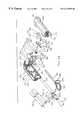
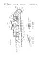
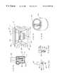
- FIG. 1is a fragmentary, partially broken, somewhat schematic view of a system embodying the invention.
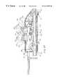
- FIG. 1Ais an enlarged fragmentary cross-sectional view of the bag fitting and pumping unit liquid inlet connector of FIG. 1 .
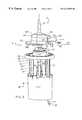
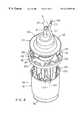
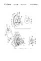
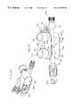
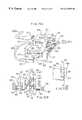
- FIGS. 2-4are exploded pictorial views of the pressure liquid unit of FIG. 1 taken from three different vantage points of differing height and circumferential location.
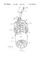
- FIG. 5is a central cross-sectional view of the pressure liquid unit of FIGS. 1-4 taken on a diametral cutting plane running through the cable space and indicated generally by the line 5 — 5 in FIG. 3 .
- FIG. 6is a central cross-sectional view similar to FIG. 5 but with the diametral cutting plane rotated to cut through a diametrically opposed pair of depending cover tabs, as generally indicated by the line 6 — 6 in FIG. 2 .
- FIGS. 7-9are pictorial views of the cup of FIGS. 2-6, taken from different viewpoints, to show the bottom of the cup in FIG. 7 and to show different viewpoints of the interior of the cup in FIGS. 8 and 9.
- FIG. 10is a central cross-sectional view of the cup, substantially as taken on the line 10 — 10 of FIG. 8 .
- FIG. 11is a top view of the FIG. 10 cup.
- FIG. 12is a bottom view of the FIG. 10 cup.
- FIGS. 13 and 14are pictorial views of the locator of FIGS. 2-4, looking respectively toward the bottom and top thereof.
- FIG. 15is a bottom view of the FIG. 13 locator.
- FIG. 16is a schematic elevational view of the electrical connections for batteries to be carried by the FIG. 13 locator.
- FIG. 17is a fragmentary generally schematic view illustrating a location of battery contacting elements in the FIG. 13 locator.
- FIG. 18is a somewhat schematic fragment of FIG. 6 showing location of the motor and battery in the locator of FIG. 13 .
- FIG. 19is a fragmentary, somewhat schematic, sectional view generally as taken on the line 19 — 19 of FIG. 6 and showing a lower battery contact.
- FIG. 20is a fragmentary, somewhat schematic, sectional view generally as taken on the line 20 — 20 of FIG. 6 and showing an upper battery contact.
- FIG. 21is a pictorial view of the motor of FIG. 19 .
- FIG. 22is a schematic representation of the electrical circuit of the FIG. 1 system.
- FIGS. 23-25are pictorial views of the pumping chamber cover of the FIGS. 2-4 apparatus, taken from the underside in FIGS. 23 and 24 and from the top in FIG. 25 .
- FIG. 26is a side elevational view of the FIG. 23 cover partially broken on a cutting plane including the central axis of the liquid outlet and cable groove.
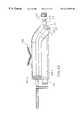
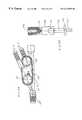
- FIG. 27is a pictorial view of the handpiece of FIG. 1 with the user actuated rocker in neutral (rest) position and the guard pin inserted for packing or shipping.
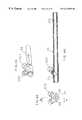
- FIG. 28is a pictorial view generally similar to FIG. 27 but taken at a different angle and omitting the guard pin and the conduit and with the rocker tilted forward.
- FIG. 29is an exploded view of the FIG. 21 handpiece drawn in reduced scale and omitting the adapter block at the rear thereof.
- FIGS. 30 and 31are respective top and bottom views of the FIG. 27 handpiece.
- FIG. 32is a side elevational view of the FIG. 27 handpiece.
- FIGS. 33 and 34are pictorial views of the irrigation side half shell of the FIG. 27 handpiece.
- FIG. 35is a side elevational view, taken from the inside, of the FIG. 33 half shell.
- FIGS. 36 and 37are pictorial views of the other half shell of the FIG. 27 handpiece.
- FIG. 38is an elevational view of the FIG. 37 half shell.
- FIG. 39is an enlarged pictorial view of the irrigation anvil of FIG. 29 .
- FIGS. 40 and 41are pictorial views of the suction and irrigation pinch levers, respectively, of FIG. 29 .
- FIG. 42is a pictorial view, taken substantially from the front, of the adapter block of FIG. 32 .
- FIG. 43is a plan view taken from above and behind of the FIG. 42 adapter block.
- FIG. 44is a pictorial view of the conduit of FIG. 29 .
- FIG. 45is a front view of the FIG. 44 conduit.
- FIG. 46is a central cross-sectional view of the FIG. 44 conduit.
- FIGS. 47, 48 and 49are substantially enlarged pictorial views of the U-spring, switch spring and Z-spring, respectively, of FIG. 29 .
- FIG. 50is an enlarged pictorial view of a subassembly of the FIG. 29 handpiece.
- FIG. 51is an enlarged top view of the FIG. 50 subassembly.
- FIG. 52is an enlarged bottom view of the FIG. 50 subassembly.
- FIG. 53is an elevational view of the handpiece above-referenced, taken from the irrigation side, with the guard pin in place but with the rear portion of the guard pin shown only in dotted line to better show internal handpiece parts located behind it and with the irrigation side half shell removed.
- FIGS. 53A and 53Bare fragments of FIG. 53 with the irrigation hose added and shown in its closed and opened positions respectively.
- FIG. 54is a view similar to FIG. 53 but with the irrigation anvil removed.
- FIG. 55is a view similar to FIG. 54 but with the irrigation pinch lever removed to show parts behind it.
- FIG. 56is a view similar to FIG. 55 but with the rocker removed and portions of the U-spring and suction pinch lever removed to better show the suction tube pinch blade opposing the corresponding anvil surface.
- FIGS. 56A and 56Bare fragments of FIG. 56 with the suction tube added and shown in its closed and opened positions respectively.
- FIG. 57is a central cross-sectional view substantially as taken on the line 57 — 57 of FIG. 31 with the rear portion of the guard pin broken away.
- FIG. 58is a view similar to FIG. 57 but showing the entire guard pin in place.
- FIG. 59is a view similar to FIG. 54 but with the guard pin entirely omitted and the rocker rocked forward in its irrigation tube open position (corresponding to FIG. 53B) and the switch contacts 323 and 315 engaged to close the battery/motor circuit and energize the motor for pumping irrigation liquid to the handpiece.
- FIG. 60is a view similar to FIG. 59 but with the rocker rocked backward to open the suction tube as schematically indicated in FIG. 56 B.
- FIG. 61is a pictorial view of a modified handpiece embodying the invention, taken from the top and left side thereof.
- FIG. 62is a pictorial view of the FIG. 61 handpiece taken from the bottom and front thereof with one bottom plug removed.
- FIG. 63is an exploded pictorial view of the FIG. 61 handpiece taken from the top, front and right side thereof.
- FIG. 64is a top view of the FIG. 61 handpiece.
- FIG. 65is an enlarged, partially broken, elevational view of a valve member of FIG. 63 .
- FIG. 66is a sectional view substantially taken on the line 66 — 66 of FIG. 64 .
- FIG. 67is a sectional view substantially taken on the line 67 — 67 of FIG. 64 .
- FIG. 67Ais an enlarged fragment of a portion of the bottom right quadrant of FIG. 67 .
- FIG. 68is a top view of the handpiece shell of FIG. 61 .
- FIG. 69is a bottom view of the FIG. 68 handpiece shell.
- FIG. 70is a sectional view substantially taken on the line 70 — 70 of FIG. 68 .
- FIG. 71is a sectional view of FIG. 70 .
- FIG. 71Ais a fragment of the right end portion of FIG. 71 with the FIG. 61 tip and an intervening annular seal added and shown in central cross section.
- FIG. 72is a cross sectional view substantially taken on the line 72 — 72 of FIG. 69 .
- FIG. 72Ais an enlarged fragment of FIG. 72 with the addition of fragments of the FIGS. 79 and 80 switch elements added and positioned in their “off” position.
- FIG. 72Bis of view similar to FIG. 72A with the switch parts in their “on” position.
- FIG. 72Cis an enlarged fragmentary pictorial view taken substantially from the same orientation as FIG. 62 with the bottom of the handpiece housing opened to show the FIGS. 79 and 80 switch elements in their installed position in the handpiece housing and in their switch “on” position.
- FIG. 72Dis an enlarged fragmentary elevational view taken generally from the orientation of FIG. 66 to show the switch opening and closing ridge in solid line in its switch “on” and in dotted lines in its switch “off” positions.
- FIG. 72Eis an enlarged fragmentary sectional view looking generally leftward from the right side of FIG. 72C or substantially on the line 72 E— 72 E of FIG. 72 D and in solid lines showing the switch “on” and in dotted line the switch “off” conditions of the switch elements.
- FIG. 73is an enlarged fragment of FIG. 69 and showing more clearly the switch carrier plates which depend within the FIG. 61 handpiece housing.
- FIG. 74is an enlarged pictorial view, taken from the bottom and one side of the suction push button of FIG. 61 .
- FIG. 75is a bottom view of the FIG. 74 push button.
- FIG. 76is a sectional view substantially taken on the line 76 — 76 of FIG. 75 .
- FIG. 77is a pictorial view taken from the bottom and one side thereof of the irrigation liquid push button of FIG. 61 .
- FIG. 78is a central cross sectional view of the FIG. 77 push button.
- FIG. 79is an enlarged pictorial view of one of the switch elements of FIGS. 63 and 72C and 72 E.
- FIG. 80is an enlarged pictorial view of the other switch element.
- FIG. 81is a pictorial view of a cap unit usable as an alternative to the closure plug for closing the rear of the conduit of FIG. 63 .
- FIG. 82is an enlarged central cross sectional view of the FIG. 81 cap unit installed on the rear end portion of the conduit of the handpiece 26 D of FIG. 63 in place of the above mentioned closure plug.
- FIG. 83is a central cross sectional view of an improved, low drag, pressure-aided shaft seal.
- FIG. 84is an enlarged fragment of FIG. 5 incorporating the FIG. 83 shaft seal.
- FIG. 85is a view similar to FIG. 83 and showing a further modification.
- the suction irrigation system 10(FIG. 1) embodying the invention comprises a pressure liquid unit 11 having a upstanding liquid inlet connector 12 for direct connection to a liquid outlet connector 13 on a conventional irrigation liquid supply IL.
- the irrigation liquid supply ILis a conventional irrigation liquid supply bag 14 and the connector 13 is a conventional luer connector.
- the irrigation liquid bag 14may be conventionally supported by the usual horizontal arm 15 adjustably fixed on the usual standing pole 16 , the arm and pole being, for example, of the kind usually employed to support an IV (intravenous) bottle, irrigation liquid bag, or the like.
- the pressure liquid unit 11may be supported from the bag 14 simply by interconnection of the respective connectors 12 and 13 .
- additional support meansmay be employed, such as a strap (not shown) fixed in any convenient way to the outside of the pressure liquid unit 11 and to the arm 15 .
- the pressure liquid unit 11may be supported by a conventional bracket 18 conventionally clamped at 19 to the pole 16 , and encircling the pressure liquid unit 11 snugly, as indicated generally at 20 .
- the pressure liquid unit 11pressurizes irrigation liquid tube 23 (FIG. 3) which is flexible and runs at length (for example 6-12 feet) to a handpiece 26 to be gripped and controlled by a user, typically a surgeon or surgical assistant.
- An electric cable 27is comparable in length to the tube 23 and runs with it from the pressure liquid unit 11 to the handpiece 26 .
- the cable 27preferably is, for neatness, fixed along the tube 23 , for example by longitudinally spaced conventional clips 32 or longitudinal bonding.
- a flexible suction tube 33runs from the handpiece 26 to a conventional suction source SS, such as a conventional hospital operating room suction port.
- the tubes 23 and 33 and cable 27preferably run to the rear end portion 34 of the handpiece 26 .
- the handpiece 26 in the embodiment shownhas a rigid tubular tip TP (hereafter described) releasably extending forward from the front end portion 36 thereof for direction toward a surgical site, either directly or through a conventional endoscopic cannula (a fragment of which is schematically indicated at CA in FIG. 1 ), for performing irrigation and suction removal of debris at a surgical site SU.
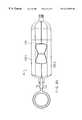
- the pressure liquid unit 11comprises (FIG. 2) a housing generally indicated at 40 , in turn comprising an upward opening cup 41 , a motor and battery locator 42 and a pump cover 43 .
- the cup 41comprises an open top 50 (FIGS. 7 - 9 ), a slightly downward tapered side/wall 51 and a generally closed bottom wall 52 .
- the bottom wallas an upstepped central motor support drum 53 .
- the drumis of circular cross-section.
- An annular, upward facing, battery receiving groove 54is defined radially and coaxially between the cup side wall and drum.
- the battery and motor locator 42(FIGS. 6 and 13) comprises a deck 60 adapted to seat upon the top edge of the cup side wall 51 and substantially close the open top of the cup 41 .
- a finned column 61fixedly coaxially depends from the deck 60 .
- the columncomprises a hollow tubular wall 59 defining a downward opening recess 62 located coaxially therein and closed at its top by the deck 60 .
- the finned exterior of the column 61is defined by a plurality (here eight for example) of circular cross-section grooves 63 extending the length of the column.
- the grooves 63are circumferentially evenly spaced and circumferentially separated by axial, curved cross-section, ridge-like fins 65 radially outwardly extending from the tubular wall 59 .
- the radially outermost surface 64 of the columnis somewhat tapered downward in correspondence to the taper of the sidewall 51 of the cup.
- the circular cross-section grooves 63have axes similarly convergent downward toward the central axis of the locator 42 (and thus toward the central axis of the recess 62 and deck 60 ).
- the grooves 63thus have bottom portions which cut into the recess 62 at the arched notches 66 .
- the column 61is sized to depend snugly into the cup 41 , with the deck 60 mounted atop the side wall 51 of the cup. In this installed position, the bottom of the hollow column 61 extends down into the annular groove 54 between the drum and side wall of the cup and the drum 53 is snugly but slidably received upward into the bottom portion of the central recess 62 of the locator. With the locator 42 installed in the cup 41 , the fins 65 have their bottom ends 67 (FIGS. 5 and 6) spaced above the bottom wall 52 of the cup 41 .
- the locator 42 and cup 41when assembled, are intended to locate therewithin in a circumferential array, plural (here eight) conventional AA batteries B (FIGS. 17 and 18 ), one in each of the circumferentially distributed grooves 63 of the locator, and a battery powered motor M in the recess 62 .
- the motor Mis, in the embodiment shown, shaped generally as a right circular cylinder with coaxially protruding top and bottom bosses 70 and 71 .
- a shaft 72extends coaxially up through the top boss 70 and is rotatable with respect thereto. See particularly FIGS. 5 and 21.
- the motor Mis snugly but slidably received up into the recess 62 of the locator 42 with its shaft 72 extending up through a coaxial hole 73 in the deck 60 .
- a conventional annular seal 74(FIG. 5) recessed in the top of the deck 60 , admits the shaft 72 rotatably upwardly therethrough but prevents liquid leakage therepast downward along the shaft toward the top of boss 70 .
- the motor Mis coaxially located in the recess 62 by snug reception of its top boss 70 in a down facing central recess 75 in the deck 60 , and its bottom boss 71 in a central opening 76 in the top of the drum 53 (FIGS. 7 and 8 ).
- the top and sides of the drum 53are cut by three evenly circumferentially spaced pairs of parallel slots 80 communicating with the central opening 76 .
- the parallel slots 80 of each pairdefine therebetween a generally L-shaped segment 81 of the drum top and side walls.
- the upper and radially inner ends of the three segments 81are enlarged in cross-section to define corresponding circumferentially spaced rim parts 82 which together define the central opening 76 through the top of the drum.
- the rim parts 82are slightly wedge-shaped, to converge downwardly slightly and thereby tend to center therebetween, in wedging fashion, the bottom boss 71 of the motor M.
- the L-shaped segments 81being separated from the rest of the drum 53 by the flanking slots 80 , can resiliently deflect, in the manner of a leaf spring, to snugly grip the bottom boss 71 of the motor M and thereby firmly and fixedly center the motor M coaxially with respect to the cup 41 and locator 42 .
- upper contacts 86each comprise a generally straight bight flanked by integral coil compression spring portions 88 of frustoconical profile.
- the profile of each coil spring portions 88tapers downwardly as seen in FIGS. 17 and 18.
- the bight 87 and widened base of each spring portion 88is backed by the underside of the deck 60 .
- the coil spring portions 88each are snugly frictionally gripped by the surrounding fins 65 to firmly hold each upper contact 86 axially against the underside of the deck 60 .
- the upper contacts 86are easily installed on the column 61 by placing same in registry with the bottom end 67 (FIG. 14) of the corresponding fin 65 and then sliding same there along upwardly into contact with the underside of the deck 60 .
- Conductive, flat plate, lower contacts 92each comprise a pair of circumferentially spaced circular disks 93 connected by an integral circumferentially extending strap 94 .
- the strap 94is cut in the middle to form respective terminal tabs 94 A (FIGS. 17 and 19) for connection of the batteries B, in circuit with the motor M and a switch SW hereafter described.
- the disks 93are respectively fixedly located coaxially with the grooves 63 of the column 61 but are spaced below the column 61 to lie fixedly atop the bottom wall 52 of the cup 41 , within the annular groove 54 thereof.
- the disks 93are fixed atop the cup bottom wall 52 by any convenient means.
- the lower contacts 92were installed in a particularly advantageous manner while producing the cup 41 by injection molding.
- the bottom wall 52 of the cup 51is perforated by circumferentially spaced large and small holes 52 L and 52 S respectively. Same are left by wide and narrow mold pins (not shown) upstanding from a (not shown) mold floor underlying the bottom wall 52 (FIG. 10) of the cup 41 when forming same by molding.
- Eight of the conductive circular disks 93(FIG. 19) were continuously connected in a circle by the straps 94 and supported just above the mold floor by the wide mold pins which produce the larger diameter holes 52 L above-mentioned.
- the motor Mrequires a nominal 12-volt DC power supply. Accordingly, it is appropriate to provide eight batteries B of the nominal 11 ⁇ 2 volt inexpensive, commercially available AA type. In view of their long shelf life and relatively high power storage capability and capability to supply adequate voltage until nearly fully discharged, alkaline batteries are preferred.
- the motor Mhas a pair of electrical contacts MC protruding from the bottom thereof and electrically energizable for rotating the motor shaft.
- circumferential extensions 83 of the slots 80are diametrically opposed in the top of the drum 53 and the electric contacts MC of motor M extend downwardly therethrough for electrical connection in circuit with the batteries B and the switch SW hereafter described.
- Circumferentially spaced ribs 95extend upward along and protrude radially in on the sidewall 51 of the cup 41 and closely radially oppose corresponding ones of the fins 65 of the locator 42 .
- the radially outer part of the one of the fins 65is eliminated, as indicated at 65 A in FIG. 13, and its corresponding upstanding cup rib 95 is eliminated, leaving a cable space 96 radially therebetween.
- Electric cable 27(FIG. 5) extends through this cable space 96 , substantially vertically along the cup sidewall 51 and exits up through a cable port 101 in the deck 60 near the edge thereof and down through a cable port 102 in the bottom wall 52 of the cup 41 .
- the electric cable 27here incorporates two insulated electric wires generally indicated at 103 .
- the cover 43(FIGS. 2-6 and 23 - 26 ) includes a downwardly opening dome 110 , a radially outward extending bottom flange 112 and the inlet connector 12 .
- the inlet connector 12takes the form of a hollow spigot upstanding from the top of the dome 110 and, as seen in FIG. 6, provides an irrigation liquid inlet conduit down through the top of the dome 110 and into a pump chamber 113 occupying the upper part of the dome 110 .
- a recess 114(FIG. 5) is stepped radially outward slightly from the pump chamber 113 and extends downward therefrom through the bottom of the cover 43 .
- the central portion of the deck 60(FIGS.
- a resilient, annular seal 116(FIG. 6) is trapped vertically between axially opposed steps adjacent the top of the recess 114 and plug 115 to seal the bottom of the pump chamber 113 .
- a preferably conventional centrifugal pump rotor 117(FIGS. 5 and 6) is fixed coaxially atop the motor shaft 72 in the pump chamber 113 .
- the motor shaft 72 and pump rotor 117are preferably coaxial with the liquid inlet 12 .
- An outlet passage 120extends tangentially from the pump chamber 113 within a tangential extension 121 (FIG. 2) of the dome 110 and has an enlarged diameter outlet recess 122 adapted to fixedly sealingly receive therein the end of the irrigation liquid tube 23 as seen for example in FIG. 2, to pump irrigation liquid into the tube 23 .
- a downwardly and radially outwardly opening groove 123which is blind at its radially inner end. With the cover fixed in its proper location atop the locator 42 , the blind groove opens downward into the upper cable port 101 in the deck 60 of the locator 42 , to route the cable 27 (FIG. 5) upward and radially outward and away from the pressure liquid unit 11 and along the path of the irrigation liquid tube 23 , as generally indicated in FIG. 1 .
- the cup 41 and locator 42 and cover 43are fixed together, preferably by snap fit connections, as follows.
- the deck 60(FIG. 4) has an upwardly and downwardly thickened rim 124 . Radially inboard from the rim 124 , the deck 60 is axially punctured by circumferentially extending, circumferentially spaced slots 125 and 126 . The slots 125 alternate circumferentially with the slots 126 .
- Circumferentially spaced, generally L-profile tabs 130each depend slightly bendably from the perimeter edge of the cover 43 and insert downward into a respective slot 125 in the deck 60 .
- Each tab 130has a radially outward extending lip 131 (FIGS. 4 and 6) which snaps radially outward under the deck rim 124 to hold the cover 43 fixed downward firmly against the deck 60 of the locator 42 .
- the slots 126each have a circumferentially extending step 132 upset radially inward from the rim 124 near the bottom of such slot 126 , as indicated for example in FIGS. 4 and 13.
- Circumferentially spaced tabs 133extend up from the sidewall 51 of the cup 41 and are generally L-shaped, each having a shallow radially outward extending lip 134 .
- the tabs 133are circumferentially in register with the remaining slots 126 in the locator deck 60 .
- the tab lips 134Upon bringing the cup 41 upward coaxially toward the deck 60 , the tops of the tabs 133 enter the slots 126 .
- the tab lips 134each advance upward past, and are deflected resiliently radially inward by, the corresponding step 132 to snap over such step 132 .
- cup 51 , locator 42 and cover 43may be of any desired rigid material and manufactured in any desired way it is convenient to mold same each in one piece, of a conventional plastics material.
- a circular, disk-like label of generally rigid materialsuch as cardboard, styrofoam, or the like, fits snugly up into the downward opening recess 55 (FIG. 3) defined by downward extension of the sidewall 51 a short distance below the bottom wall 52 .
- Such labelmay be fixed in place as a last step in the assembly operation, by adhesive bonding or by press fit upward into the recess 55 due to the slight downward taper of the cup side wall 51 .
- a suitable diskis indicated at 56 in FIGS. 4 and 5.
- the disk 56can be used to cover holes in the bottom wall 52 and wiring between the cable 27 and motor contacts MC and battery lower contacts 93 .
- Such disk 56could also be used as a label for describing the product, usage and warnings regarding misuse.
- the spring wire upper contacts 86 and lower contact disks 93are located to connect the eight batteries B in series, as seen in FIG. 16 and as schematically indicated at 8 ⁇ B in the FIG. 22 circuit diagram.
- the series battery connection 8 ⁇ Bis in turn connected in series loop (through the endmost disks 93 ) with the motor M (through its contacts MC) and (through the conductors 103 of the cable 27 ) with the manually actuable switch SW (hereafter described, in the handpiece 26 ) as shown in FIG. 22 .
- the handpiece 26comprises an outer shell conveniently defined by opposed concave half shells 200 S and 200 I located respectively on the suction and irrigation sides of the handpiece, as generally indicated in FIGS. 27-29.
- the edges 201 of the half shell 200 Soverlap edges 202 of the half shell 200 I (FIGS. 33-38) and are fixed thereto by any convenient means such as conventional snapfit connections 203 and 204 respectively, or by adhesive bonding, or the like.
- An elongate rigid conduit 210extends longitudinally through the lower portion of the shell 200 and has front and rear end portions 211 and 212 which respectively protrude forwardly and rearwardly through front and rear openings 213 and 214 respectively in the substantially radial front wall and in the somewhat downward angled rear end portion 268 of the shell 200 (FIGS. 29 and 57 ).
- Longitudinally spaced ribs 217 in the half shells 200 S and 200 Iradially fix conduit 210 therein.
- Transversely extending tabs 220 (FIGS. 44 and 45) fixed on the conduit 210are received in ports 221 (FIGS. 35 and 38) opening toward each other in the half shells 200 S and 200 I to locate the conduit longitudinally fixedly in the shell 200 , as seen for example in FIG. 29 .
- annularly ribbed, hollow, tubular suction and irrigation fittings 222 I and 222 Srigidly connect to the front portion 211 of the rigid conduit 210 inside the shell 200 , adjacent the front wall 215 thereof as seen in FIG. 53 .
- the fittings 222 S and 222 Idiverge upwardly and angle rearwardly for fixed securement thereon of respective resiliently pressurably closeable, normally open hoses 224 S and 224 I (FIG. 29 ).
- the downward and rearward angled rear opening 214 of the shell 200is normally occupied by an adapter block 225 (FIGS. 42, 43 , 53 and 57 ) fixed into the rear opening 214 (FIG. 53) of the shell 210 during assembly of the two half shells 200 S and 200 I.
- the adapter block 225(FIGS. 42 and 43) has laterally protruding, partially circumferentially extending, locator ribs 226 fixed thereon. Reception, during assembly of the half shells together, of the ribs 226 snugly between a forward/rearward spaced pair of further ribs 227 (FIGS.
- the adapter blockfurther comprises a laterally spaced pair of generally upwardly and forwardly aimed, externally ribbed fittings 230 S and 230 I (FIGS. 42 and 43) for receiving thereon, in fixed liquid tight coupled relation, the rear ends of the pinchable hoses 224 S and 224 I respectively.
- the fittings 230 S and 230 Iare similar in form to the fittings 222 S and 222 I above discussed.
- Passages indicated in broken lines at 231extend from the open front of the fittings 230 S and 230 I rearward through the adapter block and open through the rear end face 232 thereof and are adapted to fixedly and nonleakingly receive, in any conventional manner not shown, the front ends of the suction tube 33 and irrigation liquid tube 23 , as indicated in FIGS. 42 and 43.
- the rear end portion 212 of the rigid conduit 210may be closed by a cap 233 (FIG. 32) releasably secured thereon, by any convenient means such as threads.
- the cap 233may be removed to enable insertion forwardly through the conduit 210 of an elongate instrument, or other aid to surgery, whose front end is to be positioned adjacent the surgical site.
- the hollow cylindrical tip TP(FIG. 53) is mountable removably on the front end portion 211 of the rigid conduit 210 .
- An O-ring 234 or the like in an annular groove 235 in the conduitsealingly engages the hollow tip TP fixedly to the front end of the conduit 210 .
- the rear end portion 212 of the rigid conduit 210passes snugly, but slidably, rearward through a central hole 236 in the adapter block 225 (see FIGS. 42, 43 and 57 ).
- a transverse shaft 240(FIG. 29) extends across the interior of the shell 200 and has its ends fixed in transversely opposed, tubular bosses 241 (FIGS. 29, 35 and 38 ).
- the shaft 240is located about mid-height in the shell 200 .
- An irrigation pinch lever 242 and a suction pinch lever 243are located on the shaft 240 , adjacent the irrigation half shell 200 I and suction half shell 200 S respectively.
- the pinch leverseach have mid portions pivoted on the shaft 240 and each extends forward and rearward from the shaft.
- the levers 242 and 243each have a through bore 244 for pivoting on the shaft 240 a round edged pinch blade 245 extending from one side thereof adjacent the bore 244 , and a pair of tabs 246 and 247 extending from the other side thereof at respective opposite ends thereof.
- the tabs 246are flat and the tabs 247 are domed.
- the pinch levers 242 and 243differ only in that the domed tab 247 of the irrigation pinch lever 242 is somewhat flattened, as seen at 248 (FIG. 41 ).
- the pinch levers 242 and 243are each assembled on the shaft 240 so that the elongate pinch edge 249 of the blade 245 faces upward but wherein the two pinch blades 245 extend laterally away from each other and toward their respective half shells 200 S and 200 I.
- the pinch levers 242 and 243are oriented on the shaft 240 such that their respective tabs 247 and 246 are forwardmost (leftwardmost in FIG. 29 ).
- a resilient metal U-spring 252(FIGS. 29 and 47) of springy sheet metal comprises a U-shaped portion 253 comprising a pair of legs 254 depending from a bight 255 . Holes 256 through the lower portion of the legs 254 receive the shaft 240 to pivotly locate the U-spring 252 on the shaft 240 snugly between the pinch levers 242 and 243 and with the bight 255 spaced up above the shaft 240 .
- a leaf spring-like arm 257extends rearward and downward from the bight 255 . The free end portion 258 of the arm 257 is bent sharply to extend forward and somewhat upward between the legs 254 in spaced relation between the bight 255 and holes 256 .
- a coil torsion spring 261(FIG. 29) comprises a central portion 262 wrapped around the shaft 240 between the U-spring legs 254 and from which central portion extends a pair of generally rearwardly extending elongate legs 263 I and 263 S which are vertically trapped between and resiliently urge vertically apart the rear tabs 246 and 247 of the pinch levers 242 and 243 (FIGS. 52 and 53 ).
- a rigid, preferably unitary, anvil 270(FIGS. 29 and 39) comprises a fore/aft extending bar 271 locatable between the half shells 200 S and 200 I (FIG. 29) and spaced above the shaft 240 .
- a horizontal shaft 272(FIG. 39) extends toward the half shell 200 S.
- the baris widened toward the half shell 200 I to form a downwardly stepped, downwardly facing anvil surface 273 .
- a hole 274 in the rear end portion of the bar 271is coaxial with the shaft 272 and faces in the opposite direction, namely toward the half shell 200 I.
- the bar 271is generally L-shaped, as seen from above, having a leg 275 aimed toward the half shell 200 S and terminating in a pin 276 .
- the anvil 270is fixed with respect to half shell 200 S by entry of the free end of its shaft 272 and the pin 276 into corresponding holes 280 and 281 in, and adjacent the top of, the half shell 200 S (FIGS. 29, 37 and 38 ) and by entry of a pin 282 (FIGS. 34 and 35 ), fixed within the opposite half shell 200 I just below the top thereof, into the opposed hole 274 in the rear portion of the anvil 270 . In this manner, the anvil 270 is firmly fixed within the assembled shell 200 .
- the anvil 270is spaced above the irrigation pinch lever 242 , with its down facing anvil surface 273 directly opposing the upfacing pinch edge 249 of the pinch blade 245 of the irrigation pinch lever 242 (FIGS. 52 and 53) for coaction therewith in pinching and unpinching the irrigation hose 224 I which is routed therebetween.
- a further anvilwhich may termed the suction anvil, 283 (FIGS. 29, 37 and 56 ) is fixed in and preferably formed integrally with the half shell 200 S and has a down facing anvil surface 284 underlying the upper shaft hole 280 and at about the same height as the anvil surface 273 cooperating with the irrigation pinch lever 242 above-described.
- the down facing anvil surface 284overlies and cooperates with the upfacing pinch blade edge 249 of the suction pinch lever 243 for pinching and unpinching the suction hose 224 S routed therebetween.
- a hand actuable rocker 290(FIG. 29) comprises a generally box-like body 291 (FIG. 50) having parallel upstanding side walls 292 and convexly rounded, upwardly converging front and rear end walls 293 .
- the body 291includes a relatively large, generally rectangular, downwardly opening recess 294 (FIG. 57 ).
- the body 291extends down through an opening 295 in the top of the shell 200 .
- the bodyis topped by fixed, preferably integral, divergently angled, front and rear push pads 296 and 297 .
- the recess 294 of the rocker 290receives upwardly thereinto the upper portion of the U-shaped part 253 of the U-spring 252 , the top of the U-shaped part 253 being spaced below the top of the recess 294 in the rocker.
- the upper (anvil) shaft 272(FIGS. 29 and 57) extends laterally through holes 300 in the sides 292 (FIG. 50) of the rocker 290 .
- the anvil shaft 272also extends through aligned holes 301 in the upper parts of the U-spring legs 254 (FIG. 56 ).
- the U-springis substantially fixed in place with respect to the shell 200 by passage of the upper and lower shafts 272 and 240 therethrough and the rocker 290 (FIG. 57) is pivoted on the anvil shaft 272 for rocking forwardly and rearwardly (clockwise or counterclockwise in the drawing) about the anvil shaft 272 .
- the forwardly and upwardly angled front end portion 258 of the U-spring 252lies within the downward opening recess 294 of the rocker 290 and at its forward extremity (left extremity in FIG. 57) is fixed to the front wall 293 of the rocker 292 by any convenient means, such as by being molded integrally with the rocker 290 .
- the U-spring 252is arranged to resiliently urge the rocker 290 to its central, horizontal position shown in FIG. 57 and to resiliently resist, but permit, forward and rearward (in FIG. 57 counterclockwise and clockwise) rocking of the rocker 290 by the user.
- the rocker 290is pivotable forward (counterclockwise in FIG. 57) to push the bottom edge of its front wall 293 down against irrigation lever front tab 247 , correspondingly counterclockwise rotate the irrigation pinch lever 242 , cause its pinch blade 245 to drop away from the corresponding irrigation hose 224 I, and thus open the irrigation hose 224 I, as in the transition from FIG. 53A to FIG. 53 B.
- the rocker 290is pivotable rearward (clockwise in FIG.
- the electrical switch SW of the handpiece 26is formed by a switch spring 310 and a Z-spring 311 , seen in FIGS. 48 and 49 respectively. Both are formed of resiliently deflectable, electrically conductive, sheet metal.
- the switch spring 310comprises a base plate 312 having a free end provided with gripper tabs 313 reflexly bent, a generally L profile female electric terminal 314 and a switch contact arm 315 .
- the Z-spring 311(FIG. 49) comprises a base plate 320 whose free end is provided with gripper tabs 321 , a generally L-shaped planar electric terminal 322 , and a generally Z-shaped switch contact 323 .
- the half shell 200 S(FIGS.
- a preferably integral switch actuator foot 326(FIG. 53) arranged so that forward (counterclockwise) tilting of the rocker 290 not only opens the irrigation tube 224 by dropping the pinch blade 245 (in the transition from FIG. 53A to FIG. 53 B), but also pivots the foot 326 (FIG. 59) upward and rearward, to push the switch contact 323 of the Z spring 311 rearwardly into electrical contact with the switch contact 315 of the switch spring 310 .
- rocking the rocker 290 rearwarddrops the pinch blade 245 of the suction pinch lever 243 to open the suction tube 224 (in the transition from FIG. 56A to 56 B) to allow suction flow from the tip back to a suction source SS.
- a guard pin 330(FIG. 29) has its square cross-section, elongate shank 331 inserted rearwardly through a hole 332 in front wall 333 of the shell (FIGS. 27 - 29 ).
- the guard pin shank 331(FIG. 58) extends through the front wall hole 332 rearward into the shell 200 snugly under the front and rear walls 293 of the rocker 290 to positively prevent pivoting of the rocker 290 and thereby preventing closure of the electric switch contacts 315 and 323 .
- FIGS. 53-58show the parts in this storage position, with the guard pin shank 331 in solid line in FIG. 58 and in dotted line (to better show parts behind it in the drawings) in FIGS. 53-57.
- a shield 335depends from the shank 331 near the ring 334 to partly cover and protect, during storage and shipping, the open front end of the conduit 210 .
- the guard pin 330When the apparatus is ready for use, the guard pin 330 is withdrawn from the handpiece by forward pull on a finger ring 334 (FIG. 29) fixed on the front end of the shank 331 .
- the remaining primary parts of the handpieceare formed of a suitable rigid material, by any convenient means, such as molding of a rigid plastics material.
- the inlet connector 12 of the pumping unit 11is inserted in the corresponding fitting of an irrigation liquid supply (e.g. bag) IL and the pumping unit 11 is supported therebelow by means above discussed.
- the guard pin 330is pulled from the handpiece 26 .
- the tip TP of the handpiece 26is inserted into a surgical site SU in a patient, e.g. through a cannula CA previously inserted thereinto.
- rocking the rocker 290 rearwardcloses the hose 224 I and opens the hose 224 S for suctioning debris from the surgical site through the tip TP, conduit 210 , open suction hose 224 S, adapter 225 and suction hose 33 to a conventional suction source SS.
- Release of the rocker 290causes it to resiliently center itself in its neutral FIG. 27 position, in which both the suction and irrigation hoses 224 S and 224 I respectively are clamped closed by their respective pinch levers 243 and 242 .
- the disclosed suction irrigation system 10is totally disposable and manufacturable at relatively low cost. Upon insertion of the inlet flow connector 12 into the irrigation liquid source IL, and pulling out of the guard pin 330 , the system 10 is ready for immediate use.
- the systemprovides a high flow rate of irrigation liquid (higher than usual for a disposable system). The flow rate is steady so as not to make tissue jump at the surgical site, as might a pulsed irrigation system.
- Location of motor, pump and batteries remotely from the handpiece, adjacent the irrigation liquid source ILnot only provides for substantially instantaneous priming of the pump but also permits a compact, very lightweight, and hence readily maneuverable handpiece 26 .
- the connector 13(FIGS. 1 and 1A) on the liquid supply container 14 was a conventional luer female fitting.
- the liquid inlet connector 12was provided with an annular rib 12 A (FIGS. 1, 2 and 4 - 6 ) adjacent its upper end to snapfit into the bag fitting 13 forcibly enough to support the weight of the pumping unit 11 (and its trailing hose 23 and cable 27 ) pendently from the container 14 , yet allow the pumping unit 11 to be intentionally disconnected from the container 14 by pulling same apart more forcibly.
- the pumping unit 11 with its trailing hose 23 and cable 27can be entirely supported pendently from the liquid supply container 14 by connection of its hollow spike 12 to the container fitting 13 , or can instead be supported by separate means, exemplified by the bracket 18 of FIG. 1 .
- FIG. 61 and onwarddisclose a modified handpiece 26 D.
- parts of the modified handpiece 26 Dwill carry the same reference numerals as corresponding parts of the above described handpiece 26 with the suffix D added thereto.
- the handpiece 26 Dmay be used in a variety of orientations, for example in the FIG. 61 orientation, in an orientation turned upside down therefrom as in FIG. 69, or in other orientations as desired and convenient.
- the words “top” and “bottom”shall refer to the handpiece 26 D in its orientation of FIG. 61 .
- the handpiece 26 Dcomprises a shell 400 .
- the shell 400preferably includes an inverted tub 401 .
- the shell 400preferably is a one-piece molded rigid plastic element.
- the inverted tub 401comprises upstanding, front and rear valve barrels 402 and 403 laterally spaced from each other and joined by preferably tangent side walls 404 and 405 (FIG. 68 ).
- the inverted tub 401further includes a top wall 410 which closes the top of the inverted tub 401 and extends between the barrels 402 and 403 and side walls 404 and 405 (FIGS. 68 and 70 ). Top extensions 411 and 412 of the front and rear valve barrels 402 and 403 respectively extend up past the top wall 410 .
- a pair of switch carrier plates 413 and a further pair of switch carrier plates 414depend from the top wall 410 into the downward opening cavity 415 of the inverted tub 401 .
- the plates 413 and 414are parallel to each other and preferably parallel to the side walls 404 and 405 .
- the plates 413 and 414are spaced inboard from the side walls 404 and 405 respectively.
- the plate pairs 413 and 414are spaced apart on opposite sides of the common diametral plane of the barrels 402 and 403 .
- Relatively narrow switch mounting gaps 420 and 421laterally space apart the respective complete pairs 413 and 414 (seen for example in FIG. 73 ).
- a hole 422(preferably T-shaped as in FIGS.
- the cross-head portion of the Tlies close adjacent the top extension 411 of the front valve barrel 402 and the leg of the T extends rearward therefrom and overlies the switch mounting gap 420 (FIG. 73) in vertical alignment therewith.
- the shell 400includes an elongate rigid conduit 430 (FIG. 61) which is preferably integrally molded in the tub side wall 404 adjacent the top thereof (here substantially flush with the top wall 410 ).
- the conduit 430extends forwardly and rearwardly beyond the inverted tub 401 , as seen for example in FIGS. 61 and 71 and has front and rear end portions 431 and 432 spaced from the inverted tub 401 .
- the front end portion 431 of the conduit 430is radially enlarged and carries an annular seal ring groove 434 (FIGS. 70 and 70A) for receiving a resilient seal ring (e.g.
- the radially enlarged rear end portion 432 of conduit 430is internally threaded at 436 (FIG. 70) for alternative reception therein of an externally threaded closure plug 440 (FIGS. 61 and 63) or a suitable surgical tool (not shown).
- the closure plug 440preferably is provided with an annular seal, such as an O-ring 442 (FIG. 63 ), behind its externally threaded front extremity 443 for sealing the rear end of the conduit 430 against fluid leakage, when threadedly inserted into the rear end portion 432 of the conduit 430 .
- the conduit 430has a through passage 441 axially, and preferably coaxially, extending therethrough and opening through the front and rear end portions 431 and 432 .
- Suitable surgical toolsmay be inserted forwardly through the rear end portion 432 or rearwardly into the front end portion 431 of the conduit 430 .
- Such surgical toolsmay include ones of the type having substantially coaxial inner and outer parts, wherein the inner part may be received in the through passage 441 and the outer part may be threaded onto the externally threaded front extremity 435 in a conventional manner, and in place of a tip TPD.
- the conduit 430alternately will also accommodate surgical tools (not shown) of the type having a portion similar to the plug 440 with a forward extending portion (not shown) insertable forwardly through the through passage 441 and the conduit 430 toward a surgical site.
- the front end portion 431 and rear end portion 432 of the conduit 430may be provided with removable adaptors (not shown) to present an external thread adjacent the rear end portion 432 and/or an internal thread adjacent the front end portion 431 , should it be desired to use an externally threaded tip in place of the tip TPD of FIG. 61 or an internally threaded tool portion adjacent the rear end portion 432 of the conduit 430 .
- adaptorsmay be threaded onto the front end portion 431 and/or into the rear end portion 432 for the purpose of providing a non-threaded connection of a tip or tool thereto.
- the shell 400further includes integral irrigation liquid and suction fittings (or nipples) 450 and 451 respectively (FIGS. 61, 68 and 70 ), which extend generally rearwardly at an acute angle (here about 22° and preferably between 15° and 30°) to the side wall 405 of the inverted tub 401 and conduit 430 .
- the fittings 450 and 451have respective coaxial through passages 452 and 453 respectively, whose central length axes are parallel to each other and are coplanar with the central length axis of the conduit 430 .
- the central through passages 452 and 453extend coaxially, and generally forwardly, from the nipples 450 and 451 respectively, just below the top wall 410 of the inverted tub 401 , and perpendicularly across the valve barrels 402 and 403 respectively, and have forward ends into the central through passage 441 of the conduit 430 .
- the central length axes of the irrigation and suction passages 452 and 453perpendicularly intersect respective upstanding length axes of upstanding coaxial through openings 454 and 455 respectively of the front and rear valve barrels 402 and 403 respectively (compare FIGS. 70 and 71, for example).
- the nipples 450 and 451thus communicate through the upstanding central through openings (or valve bores) 454 and 455 respectively of the front and rear valve barrels 402 and 403 respectively, and thereacross with the central through opening of the conduit 430 .
- Such communicationis controlled by valve bodies hereafter described.
- the nipples 450 and 451are on the opposite side of the inverted tub 401 , from the conduit 430 .
- the nipples 450 and 451are separated laterally from the conduit 430 by the common central plane of the valve barrels 402 and 403 (such common central plane of the valve barrels 402 and 403 being defined by (containing) the upstanding central axis of the valve bores 454 and 455 of the valve barrels.
- the front valve barrel 402is intended to control irrigation liquid flow from the nipple 450 to the conduit 430 and the rear valve barrel 403 is intended to control suction flow from the conduit 430 to the nipple 451 .
- the nipples 450 and 451are respectively adapted to connect to a suitable irrigation liquid source and suction source respectively.
- the irrigation liquid nipple 450is connectable through an irrigation liquid tube 23 D supplied by a pump 11 D from an irrigation liquid source IL, as described above with respect to the embodiment of FIG. 1 in respect to the irrigation liquid tube 23 , pump 11 and irrigation liquid source IL.
- the suction nozzle 451is connectable through a suction tube 33 D to a suction source SS, as above discussed with respect to the embodiment of FIG. 1 in respect to the suction tube 33 and suction source SS.
- the front and rear valve barrels 402 and 403may thus be referred to as the irrigation liquid and suction valve barrels respectively.
- the handpiece 26 D(FIG. 63) includes axially shiftable valve members 460 and 461 (FIG. 63) respectively cooperable with the valve barrels 402 and 403 to accommodate the respective valve members 460 and 461 , the valve bores 454 (FIG. 70) and 455 .
- the valve bores 454 and 455each include a bottom cylindrical guide portion 462 (FIG. 70 ), surmounted by an upward tapered valve seat 463 , and in turn surmounted by a narrower cylindrical valve guide portion 464 .
- a radially enlarged cylindrical bottom opening recess 465communicates between the bottom cylindrical guide portion 462 and the bottom of the inverted tub 401 , as seen in FIG. 70 .
- the irrigation liquid and suction through passages 452 and 453pass through and are spaced from the top and bottom of their respective upwardly tapered valve seats 463 and are thus spaced below the corresponding narrowed cylindrical valve guide portion 464 and are spaced below their respective narrowed cylindrical valve guide portions 464 .
- each valve member 460 and 461comprises an elongate cylindrical valve piston 470 pierced at its bottom end by a diametral fluid hole 471 and having at about mid-height an annular groove 472 for receiving an annular seal (conveniently an O-ring) 473 (FIG. 66 ).
- a coaxial multi-sided (here rectangular) top hole 474(FIG. 63) indents the top of each piston 470 .
- a preferably cylindrical rod 475coaxially depends from each piston 470 .
- a coaxial radially outwardly extending annular flange 476is fixed at the bottom of each rod 475 .
- a spring guide tail 477coaxially depends from each radial flange 476 , and also serves as a stop for the corresponding piston 470 at the bottom of its axial travel as seen in FIG. 67 .
- Each valve member 460 and 461further includes a hollow, resilient, upward tapering, preferably frustoconical valve closure element 482 (FIG. 63) snugly fixed on the corresponding rod 475 between the bottom of the corresponding piston 470 and the top of the radial flange 476 , as shown in the assembled condition of the valve member (for example the suction valve member 460 and 461 ) in FIGS. 66 and 67.
- a hollow, resilient, upward tapering, preferably frustoconical valve closure element 482(FIG. 63) snugly fixed on the corresponding rod 475 between the bottom of the corresponding piston 470 and the top of the radial flange 476 , as shown in the assembled condition of the valve member (for example the suction valve member 460 and 461 ) in FIGS. 66 and 67.
- the open bottom of the inverted tub 401 and the bottom opening recesses 465are closed by a bottom closure, here comprising a laterally opposed pair of bottom plugs 483 (FIG. 63 ).
- the bottom plugs 483are preferably identical and each comprises a generally D-shaped closure plate 484 and an upward opening cup 485 fixedly upstanding integrally from the rounded end of the corresponding D-shaped closure plate 484 .
- the open bottom of the inverted tub 401is closed by the closure plates 484 of the respective front and rear bottom plugs 483 , and the cups 485 are snugly and sealingly telescoped in and close the open bottoms of the respective front and rear barrels 402 and 403 , as generally indicated in FIGS.
- the bottom of the tub 401is closed (but need not be sealed) by the plates 484 , whereas the bottoms of the front and rear valve barrels 402 and 403 are plugged and sealed by the respective cups 485 of the bottom plugs 483 .
- the bottom plugs 483may be, and preferably are, permanently fixed in the bottom portion of the inverted tub 401 by any convenient means to trap within the valve barrels the valve members 460 and 461 and trap within the open central portion of the inverted tub 401 electrical contact structure hereafter described.
- sealing of the bottom of each barrel 402 , 403is by pressfitting therein of the corresponding cup 485 , which pressfitting also serves to fix the bottom plugs 483 to the inverted tab 401 .
- the outside of the cup 485at a location spaced between its top and bottom ends, may be externally annularly grooved to receive an annular resilient seal, preferably a conventional O-ring 486 (FIG. 67 A), wherein the O-ring 486 assists or provides such sealing.
- the bottom plugs 483may be fixed to the inverted tub 401 in other ways, for example by sonic welding, adhesive bonding, or the like. Alternately, if desired, the bottom plug pair 483 can be combined into one single port.
- Each of the valve members 460 and 461is resiliently urged into its upper, closed position (shown for example with respect to the front, irrigation liquid valve member 460 of FIG. 66) by a corresponding coil compression spring 490 (FIG. 67 ).
- the coil spring 490is backed at its lower end by the corresponding bottom plug 483 .
- each spring 490radially loosely sits in its cup 485 .
- the upper end portion of each spring 490telescopes coaxially on the depending spring guide tail 477 and abuts the underside of the radial flange 476 of the corresponding valve member 460 or 461 .
- the springs 490thus urge the valve members 460 and 461 to their closed (upper in FIG. 67) positions disconnecting the corresponding one of nipples 450 and 451 from the conduit 430 .
- Front and rear (here irrigation liquid and suction, respectively) inverted cup shaped push buttons 491 and 492are coaxially fixed to the top of the corresponding front and rear valve pistons 470 (FIGS. 63 and 66 ).
- a hollow, rectangular cross section, preferably integral stem 493fixedly depends coaxially from the top wall 494 (FIG. 78) and down into the hollow interior of each inverted cup-shaped push button.
- Each stem 493depends partway, here about halfway, through the height of the inverted cup shaped push button 491 and 492 and is of non circular (in the preferred embodiment shown rectangular) cross section for snug, non-rotatable fixed reception in the preferably corresponding cross-section, multi-sided top hole 474 in the corresponding valve piston 470 (FIG. 63 ).
- each valve piston 470and hence its diametral fluid hole 471 are circumferentially fixed with respect to the corresponding one of the manual actuable push buttons 491 and 492 .
- the push buttons 491 and 492may be fixed to the tops of their respective valve pistons 470 by any convenient means such as adhesive bonding, press fit, or the like.
- the push buttons 491 and 492are snugly but axially reciprocatingly telescoped over the upstanding top extensions 411 and 412 (FIG. 63) of the shell 400 .
- the upstanding, telescoped radially opposed sides of each top extension 411 , 412 and its corresponding push button 491 , 492are of constant diameter (cylindrical) through its height for snug reciprocating movement of each push button 491 , 492 on its corresponding upstanding top extension 411 , 412 .
- the height of the top extensions 411 , 412 and push buttons 491 , 492are about the same, as seen in FIG. 66 .
- Each corresponding valve piston 470 in its uppermost, rest, closed position shown in FIG. 66protrudes up beyond the top of the corresponding top extension 411 or 412 , such that with the corresponding valve piston 470 in its uppermost position as in FIG. 66, the corresponding inverted cup-shaped push button 491 , 492 is about half telescoped over the corresponding top extension.
- the upstanding top extensions 411 and 412(FIG. 63) each have at least one upstanding guide groove 495 extending the height thereof and axially slidably receiving a corresponding guide rib 496 (FIGS. 74 and 77) fixed, preferably integrally, on the interior of the side wall of the respective push button 491 and 492 for positively preventing rotation of each push button 491 and 492 on its upstanding top extension 411 and 412 respectively as the push button moves up and down axially along such top extension.
- the ribs 492preferably extend the entire height of the corresponding push buttons 491 and 492 and are complimentary in size and cross sectional shape to the corresponding guide grooves 495 to allow free relative axial movement but preclude relative circumferential movement as between the push buttons and top extensions.
- the axial guiding of the ribs 492 in the grooves 495keeps the valve pistons' diametral fluid holes 471 aligned with the corresponding irrigation liquid and suction through passages 452 and 453 respectively of the nipples 450 and 451 respectively.
- diametrally opposed pairs of guide grooves 495 on each top extension and diametrally opposed pairs of ribs 496 on each push buttonare provided.
- the two pairs of guide grooves 495 on the top extensions 411 and 412are coplanar, and hence lie on the common central plane of the top extensions 411 and 412 and inverted tub 401 .
- the push buttons 491 and 492are preferably identical.
- the front (irrigation liquid) push button 491is additionally provided with a switch actuating leg 500 preferably molded in the outer surface of its side wall.
- Such actuating leg 500extends down the height of the push button 491 and thence downward beyond the bottom edge of the push button 491 in the manner shown in FIG. 63 .
- At least the dependent portion of the switch actuating leg 500is of constant cross section and is shaped and sized and located circumferentially of the front push button 491 to be smoothly vertically reciprocatingly received down into the cross head portion of the T-shaped hole 422 (FIG. 68) in the top wall 410 of the inverted tub 401 .
- the T-shaped hole 422 and switch actuator leg 500are offset slightly sideways from the common central plane of the top extensions 411 (marked by the corresponding section line in FIG. 68 ).
- the depending portion of the switch actuating leg 500is conveniently of U-shaped cross section as seen in FIG. 77 .
- a switch contact separating ridge 501Fixed, preferably integrally, to the bottom portion of the leg 500 and protruding rearwardly therefrom is a switch contact separating ridge 501 .
- the hole 422continues as a shallow downwardly extending groove 502 in the portion of the forward valve barrel 402 facing into the interior of the inverted tub 401 . As seen in FIG. 73, such groove 502 helps guide longitudinal reciprocation of the switch actuator leg 500 inside the inverted tub 401 .
- FIG. 22 of the prior embodimentAn electrical switch like that indicated schematically at SW in FIG. 22 of the prior embodiment is provided for actuation to energize a pump motor like that shown on at M in above FIG. 22 from batteries such as indicated at B therein.
- switch SWcomprises a pair of switch elements 510 and 511 (FIGS. 63, 79 , 80 and 72 C) of electrically conductive springy sheet metal, such as copper or a suitable alloy.
- the switch element 510(FIG. 80) comprises a base plate 512 provided with gripper tabs 513 acutely angled with respect thereto.
- the switch element 510further includes an electric connector terminal 514 and a switch contact leaf 515 .
- the switch element 511is of somewhat different shape, but includes a base plate 520 (FIG. 79) including gripper tabs 521 acutely angled with respect thereto, and an electric connector terminal 522 and switch contact leaf 523 extending therefrom.
- the switch element 510is fixed in the interior of the inverted tub 401 as follows.
- the base plate 512is slidably inserted upward in the orientation of FIG. 63 into the switch mounting gap 421 (FIGS. 72C and E) between the depending switch carrier plates 414 .
- the gripping tabs 513enter and become jammed in the switch mounting gap 421 to prevent the switch element 510 from accidently leaving its operative position of FIGS. 72C and E, within the inverted tub 401 .
- the electrical connection terminal 514lies between the outboard switch carrier plate 414 and the side wall 403 of the inverted tub 401 .
- the switch contact leaf 515is resiliently self-urged toward the switch carrier plates 413 as more fully discussed hereafter.
- the base plate 520 of the switch element 511is inserted upward into the switch mounting gap 420 (FIGS. 72C and E) and is frictionally fixed therein by engagement of the gripping tabs 521 with the opposed inboard switch carrier plate 413 .
- the electrical connector terminal 522is disposed between the outboard switch carrier plate 413 and the inverted tub side wall 404 adjacent the bottom of the outboard side wall 413 .
- the switch contact leaf 523extends upward along the outboard switch carrier plate 413 within the switch mounting gap 420 and into electrical contact with the switch contact leaf 515 of the switch element 510 to complete an electrical connection between the two switch elements 510 and 511 .
- Wires 103 of cable 27 (FIG. 22) from the pump motor Mare indicated at 103 D in FIG. 72 C and are lead into the inverted tub 401 through an opening 524 (FIG. 61) in the top wall 410 of the inverted tub 401 .
- the wires 103 Dsuitably insulated, terminate within the inverted tub 401 in conventional connectors 525 compatible with the electrical connector terminals 514 and 522 , respectively.
- the connectors 525are of resilient female type telescopingly fixable on the electrical connector terminals 514 and 522 .
- FIG. 72C electrical contact between the leaf 515 and leaf 523acts as a switch SWD (FIG. 72C) usable in place of the switch SW (FIG. 22) and which upon closure energizes the motor M from the battery B.
- switch contact leaves 515 and 523are permitted with the switch leaf separator 501 pressed down, by pushing downward the corresponding button 591 to its lowermost position (from its upper position in FIGS. 66, 72 C and 72 E.
- push button 591Upon manual release of the push button 591 , it is raised by spring 490 to its upper position shown in FIG. 61, thereby raising the switch leaf separator ridge 501 to its dotted line position in FIGS. 72D, E, thereby pushing the switch contact leaf 515 out of contact with the leaf 523 and into its dotted line position shown at 515 ′ and opening the switch to a position like that of the switch SW FIG. 22, thereby disabling the pump motor M.
- the inboard switch carrier plate 413is recessed at 526 , in the upper portion of its edge facing the vertically shiftable switch actuating leg 500 , to provide room for up and down motion of the switch leaf separator ridge 501 .
- the handpiece 26 D(FIG. 63) may be assembled as follows.
- the assembled valve members 460 and 461(including elements 470 - 477 , 482 and 490 ) are inserted up into the open bottoms of the respective front and rear valve barrels 402 and 403 and temporarily held in place therein by any convenient means not shown.
- the push buttons 491 and 492are then fixed atop the upward protruding valve pistons 470 by any convenient means, as shown with respect to valve push button 491 and FIG. 66, for example.
- the free ends of the insulator wires 103 Dare lead up into the central portion of the downward opening cavity 415 of the inverted tub 401 and up through the opening 524 (FIG. 63) and the top wall 410 of the inverted tub 401 and extend therefrom toward the remote pressure liquid unit, like the insulated wires 103 from the handpiece 26 of FIGS. 1 and 22, for connection to the motor M and battery B in the manner of FIG. 22 .
- the forward (irrigation liquid) push button 491is then preferably pushed down (to its valve open position) to position the switch leaf separation ridge 501 in its lowest position, shown for example in FIGS. 72D-E.
- the switch contact leaf 515bent more closely toward its corresponding base plate 512 , to clear the switch carrier plates 413 (for example to the position 515 ′′ shown in chain line in FIGS. 72 - 73 )
- the switch element 510can be slid upward into its installed position in the inverted tub 401 , with its base plate 512 and gripping tabs 513 trapped in the switch mounting gap 421 between the switch carrier plates 414 .
- the switch element 511can be installed by inserting its base plate 520 , gripping tabs 521 and switch contact leaf 523 upward into the switch mounting gap 420 between the switch carrier plates 413 , to its FIG. 72E installed position, with its switch contact leaf 523 extending up past and being electrically conductively and forcibly pressed against by the upstanding free end of the switch contact leaf 515 , as shown in FIG. 72 E.
- the bottom plugs 483can then be fixed in place (in the manner above described with respect to FIGS. 66 and 67) to close bottom of the shell 400 .
- the irrigation liquid and suction tubes 23 D and 33 Dcan then be fixedly telescoped over the nipples 450 and 451 respectively of the handpiece 26 D to thereby, as schematically indicated in FIG. 70, connect the nipples 450 and 451 to the irrigation liquid pump 11 D and suction source SS.
- a hollow suction/irrigation tip TPD of any conventional typemay be fixed, sealingly, to the front end portion 431 of conduit 430 (as in FIG. 61 ).
- the rear end of the conduit 430can be closed by means such as the closure plug 440 .
- Pushing down the suction button 492opens the connection from the suction nipple 451 (and hence suction source SS) to the conduit 430 and tip TPD and thereby to a surgical site into which the tip TPD may be inserted for suction of loose material from a surgical site to the handpiece 26 D back to the suction source SS. Further depression of the suction push button 492 progressively opens the suction path between the interior of the conduit 430 and suction nipple 451 , by bringing the valve diametral fluid hole 471 into progressively more complete communication with the interiors of the suction nipple 451 and conduit 430 , the fully opened position of the suction valve member 461 being shown in FIG. 67 . Release of manual pressure atop the suction push button 492 allows the spring 490 to urge the suction valve member 461 from its FIG. 67 open position upward to a closed position comparable to that of the valve member 470 in FIG. 66 .
- the switch SWDturns on the pump motor to supply liquid to the valve member 470 .
- the diametral fluid hole 471 in each valve piston 470is preferably slightly widened lengthwise of the valve member (vertically in FIG. 63 ), to maximize flow through the hole 471 in the open position of the valve, by keeping the flow path through the piston 470 fully open, despite the axial stack-up of tolerances in each valve unit 460 , 491 and 461 , 495 .
- the minimum and maximum diameters of each diametral fluid hole 471were 0.190 inch and 0.220 inch respectively, the greater diameter of the hole 471 thus being about 15% greater than the minimum diameter of thereof. See for example, FIG. 65 .
- the conduit 430 and any desired tip TPDthus preferably are used for both suction and irrigation liquid flow.
- All the parts of the apparatus above describedare preferably molded, substantially rigid, plastics material of conventional type, except as otherwise described, e.g. the switch elements 510 and 511 of electrically conductive springy metal and the annular seals 473 and 482 and 486 of conventional resilient rubber-like material and the wires 103 D and connectors 525 .
- the rear end portion 432 of the conduit 430can instead be advantageously equipped with a one piece, molded, resilient, rubber-like cap unit 530 (FIG. 81 ).
- the cap unit 530comprises a cup like body 531 , opening forwardly (leftwardly in FIGS. 81 and 82 ), and which comprises a bottom wall 532 and cylindrical side wall 533 extending forward therefrom.
- the cap unitis sized to slide forwardly and telescopingly over the enlarged diameter rear end portion 432 of the conduit 430 to close the rear end thereof.
- the forward open end of the cap unitincludes a semi-circular cross section radially inward projecting lip 534 sized to project radially inward slightly with respect to the outside diameter of the enlarged rear end portion 432 of the conduit 430 and to be positioned slightly forward thereof to prevent unintentional rearward removal of the cup unit from the conduit 430 .
- the resilience of and inside diameter of the lip 534allows it to stretch slightly diametrally to permit resilient snap fit installation and removal of the cap unit with respect to its FIG. 82 position covering the enlarged rear end portion 432 of the conduit 430 .
- An integral elongate flexible strap 540extends outward substantially radially from the lipped front end of the cap unit and adjacent its outer end carries a resiliently stretchy loop 541 .
- the strap 540 and loop 541may be referred to as the “lasso”.
- the strap 540Prior to sliding the cap unit onto the enlarged rear end portion 432 of the handpiece conduit 430 , the strap 540 is bent and the loop 541 of the lasso is pulled forwardly snugly over the enlarged rear end portion 432 of the conduit 430 , slightly circumferentially stretching the loop 541 , in the process, until the loop 541 reaches the portion of the conduit 430 head of the enlarged rear end portion 432 thereof.
- the lassomaintains the cap unit captively tied to the rear end portion of the handpiece conduit 430 should the user wish to completely open the rear end of the conduit 430 by removing the cap unit, namely by sliding the cap unit rearwardly off the enlarged rear end portion 432 of the conduit 430 .
- the cap unitcannot be lost or misplaced but rather remains conveniently at hand for later telescoping onto the rear end portion of the conduit 430 .
- Sizing the internal diameter of the loop 541 slightly smaller than the external diameter of the enlarged rear end portion 432 of the conduit 430assures that the loop 541 will not accidentally fall off the rear end portion of the conduit 430 .
- Axial roomis provided between the enlarged rear end portion 432 of the conduit 430 and the inverted tub 401 of the handpiece to accommodate both the loop 541 and the lip 534 of the cup like body 531 .
- a coaxial column 544projects integrally from the rear end wall of the cup like body 531 , preferably more than half the depth of the cup like body 531 , with an annular space radially between the outside of the column 544 and inside of the side wall of the cup like body 531 .
- the column 544has a smooth cylindrical periphery of diameter to interfere slightly with the internal threads of the enlarged rear end portion 432 of the conduit 430 such that the column 544 is a friction fit within the enlarged rear end portion 432 of conduit 430 , tending to hold the cup-like body 531 firmly fixed with respect thereto against accidental removal and yet allow the user to pull the cup-like body 531 off the rear end of the handpiece conduit 430 at will.
- the column 544does not thread into or unthread from the internal threads 436 of the conduit rear end portion 432 but simply frictionally slides axially into and out of contact therewith, thereby eliminating any need to rotate the cap unit 530 when installing on or removing same from the rear end of the conduit 430 .
- the friction engagement between the threaded interior of the conduit rear end portion 432 and the column 544in addition to frictionally holding the cup-like body 531 fixed against accidental removal from the rear end portion of the conduit 430 , also creates an axial fluid seal therebetween to prevent leakage of fluid rearwardly out of the interior of the conduit 430 .
- the column 544in effect plugs the rear end of the conduit 430 to prevent liquid leakage therefrom.
- the axially innermost end of the column 544is relatively thin walled as indicated at 556 so that fluid pressure inside the conduit 430 tends to press radially outward on the thin resilient wall 556 to assist the fluid seal radially between the outside of the column 544 and the inside of the rear end portion of the conduit 430 .
- the interior of the column 544has front and rear forwardly and rearwardly diverging coaxial frustoconical coaxial recesses 545 and 546 (FIG. 82) normally sealed from each other by an axially thin integral diaphragm 547 .
- the intact diaphragm 547thus prevents fluid leakage from the conduit 430 through the central portion of the plug like column 544 .
- the relatively thin diaphragm 547can be intentionally pierced by pushing forward therethrough of a suitable relatively small diameter surgical tool (not shown), for example a laser probe, and in particular a surgical tool whose outside diameter is less than that of the diaphragm 547 .
- a suitable relatively small diameter surgical toolfor example a laser probe, and in particular a surgical tool whose outside diameter is less than that of the diaphragm 547 .
- the tapered recesses 546 and 545 in the column 544help to guide the axial movement of such a surgical tool forwardly into and rearwardly out of the rear end of the column.
- the diaphragm 547having been pierced by such a surgical tool, tends to at least partially seal around such surgical tool, when the latter is in place in the conduit 430 for use at a surgical site in front of the handpiece, to at least minimize liquid leakage rearwardly along the shank of such a surgical tool (not shown) and rearwardly out of the cap unit 530 .
- the central opening 550 in the bottom wall 532 of the cup-like body 531is configured to be itself plugged against fluid leakage rearwardly therethrough, as follows.
- the cap unit 530includes a further integral strap 551 extending radially from the rear end portion thereof (here extending radially from the bottom wall 532 , FIG. 82 ).
- the strap 551is readily bendable from a relaxed radially extending position shown in dotted lines in FIG.
- the strap 551carries, remote from the cup-like body 531 , an integral stopper portion 552 including a plug 553 adapted to be pushed forwardly into a correspondingly shaped, rearwardly opening, central opening 550 in the bottom wall 532 of the body 531 and which communicates axially with the rearward recess 546 .
- the integral plug 553includes a nose 554 tapered to facilitate insertion into the central opening 550 . Such insertion is aided by tapering the rearward opening mouth 555 of such central opening.
- the plug 553is spaced from the stopper portion 552 of the strap 551 by a short radially undercut neck 560 .
- the central opening 550 in the bottom wall 532is shaped to snugly compliment the plug 553 and the plug 553 can thus be pushed into a seated position within the opening 550 and can be pulled out of such position by the user with moderate axial force.
- the plug 553 when installed in the opening 550snugly seats therein in a manner to close and seal the opening 550 against fluid leakage therethrough from the interior of the conduit 430 .
- FIGS. 83 and 84disclose an improvement on the FIG. 5 pump motor shaft seal arrangement.
- FIG. 84shows the motor M with its upstanding shaft 72 carrying the pump rotor, or impeller 117 , in the pump chamber 113 .
- FIG. 5 seal 74is eliminated and is replaced with a new seal ring 570 (FIGS. 83 and 84) to be located in a widened, upward opening seal recess 571 (FIG. 84) located preferably but not necessarily coaxially around the motor shaft 72 and atop the thus modified battery and motor locator 42 D.
- the seal ring 570is generally hat shaped, comprising an annular crown 572 having a flat top 573 , a downwardly divergent outer side wall 574 and a coaxial through bore for sealingly receiving the rotating shaft 72 .
- the upper part of the through boreis formed by a lip seal 575 which is radially inwardly convexly rounded and occupies approximately the top 40% of the through bore.
- the intermediate 40% of the height of the through boreis formed by a second lip seal 576 of similar shape.
- the bottom portion of the through borediverges downwardly as indicated at 577 to form a bell-like bottom mouth 577 .
- a substantially reduced thickness brim 580extends radially outward from the bottom portion of the crown 572 and a thickened (here of substantially upstanding circular cross section) perimeter lip 581 coaxially bounds and is somewhat upstanding from the outer periphery of the substantially horizontal brim.
- the seal recess 571 in the battery and motor locator 42 Dis substantially axially deeper and radially wider than the seal ring 570 , as seen in FIG. 84 .
- the seal ring 570is of resilient rubber-like material and receives coaxially upwardly through the central bore thereof the rotatable motor shaft 72 .
- the upper lip seal 575bears sealingly on and surrounds the rotatable shaft 72 to prevent leakage of liquid from the pumping chamber 113 downward along the shaft 72 into neighborhood of the motor M.
- the convexly rounded profile of the lip seal 575minimizes the axial height of contact between it and the rotating shaft 72 to minimize frictional drag on the shaft and hence minimize waste of battery energy on friction, which battery energy is preferably to be used instead for pumping liquid.
- Increased liquid pressure in the pumping chamber 113results in increased pressure on the top 573 and frustoconical outer side wall 574 of the crown 572 , thereby tending to in fact bend the central portion of the seal ring 570 , or tilt same, inward and slightly downward toward the surface of the rotating shaft 72 generally in the direction of the arrow AR.
- the resulting increased pressure of the upper lip seal 575 on the shaft 72increases the tightening of sealing. Accordingly, the seal ring 570 seals progressively more tightly against downward leakage of liquid from the pumping chamber 113 downwardly past the periphery of the shaft 72 as liquid pressure in the pumping chamber 113 rises.
- the seal ring 570when pumping chamber pressure drops, the seal ring 570 less tightly grips the rotating shaft 72 and hence reduces friction therebetween and resulting energy loss to such friction. Accordingly, the seal ring 570 adapts to changing pressure conditions in the pumping chamber 113 to minimize energy loss to friction between itself and the rotating shaft 72 while yet providing adequate sealing to prevent liquid leakage downwardly therepast from pumping chamber 113 , to thereby protect the motor and related components from wetting by the pumped liquid.
- Liquid pressure in the pumping chamber 113also helps keep the central body crown 272 of the seal ring 570 from moving axially upwardly toward the impeller 117 .
- the perimeter of the seal ring 570is positively held against the bottom of recess 571 by an annular hoop 582 , preferably of rigid plastic material, such as ABS, press fitted down into the recess 570 into compressive contact with the top of the perimeter lip 581 of the seal ring 570 in the manner shown in FIG. 84 .
- the upstanding perimeter lip 581being of limited radial extent, thus localizes the downward pressure of the hoop 582 , which thus maximizes the downward pressure of the radially narrow perimeter portion of the seal ring 570 against the underlying bottom of the recess 571 , to provide a very effective seal against leakage of liquid from the pumping chamber 113 , which liquid might otherwise attempt to pass between the underside of the seal ring 570 and the bottom of the recess 571 , to thereby reach and drain downward along the lower portion of the rotating motor shaft 72 , into contact with the top of the casing of the motor M.
- the upstanding perimeter lip 581 of the seal ring 570tends to concentrate the force of its sealing against the bottom of the recess 571 in a radially narrow annular area located immediately below the perimeter lip 581 and indicated at NA.
- the axially thin but radially relatively wide brim 580is relatively limp and flexible and effectively resiliently isolates the shaft seal area 575 from the recess bottom seal area 581 , so that the shaft engaging lip seal 575 in effect floats radially with the shaft (should there be any radial movement of it with respect to the battery and motor locator 42 ) without influence by the sealing contact between the perimeter lip 581 and the hoop 582 and bottom of recess 571 .
- the thin flexible brim 581allows relative radial movement or misalignment between the shaft seal 575 and recess bottom seal 581 , to accommodate radial movement (vibration or otherwise) of the shaft 72 without loss of sealing capability or frictional drag.
- sealing against liquid leakage past the seal ring 570is independent of alignment between the motor shaft 72 and locator housing 42 D.
- the lower lip seal 576similarly bears on the shaft 72 and acts as a back-up seal in case of unexpected unusual failure of the upper lip seal 575 .
- FIG. 85shows a modification of the FIG. 83, 84 seal ring, same being modified by elimination of the lower lip seal 575 of FIG. 83, so that in the area below the upper lip seal 575 B of the modified seal ring 570 E, the central through bore 590 is radially recessed as indicated at 591 so as to be free of contact with the shaft 72 .
- the modified seal ring 570 Eis thus contemplated for use in situations wherein the operating life of the apparatus is to be shorter than in the FIG. 83, 84 apparatus, i.e.
Landscapes
- Health & Medical Sciences (AREA)
- Heart & Thoracic Surgery (AREA)
- General Health & Medical Sciences (AREA)
- Public Health (AREA)
- Anesthesiology (AREA)
- Hematology (AREA)
- Life Sciences & Earth Sciences (AREA)
- Animal Behavior & Ethology (AREA)
- Engineering & Computer Science (AREA)
- Biomedical Technology (AREA)
- Veterinary Medicine (AREA)
- Vascular Medicine (AREA)
- Physics & Mathematics (AREA)
- Fluid Mechanics (AREA)
- Pulmonology (AREA)
- Surgical Instruments (AREA)
- External Artificial Organs (AREA)
Abstract
Description
Claims (44)
Priority Applications (3)
| Application Number | Priority Date | Filing Date | Title |
|---|---|---|---|
| US08/769,428US6213970B1 (en) | 1993-12-30 | 1996-12-19 | Surgical suction irrigation |
| US09/676,517US6623445B1 (en) | 1993-12-30 | 2000-10-02 | Surgical suction irrigator |
| US10/648,693US7297133B2 (en) | 1993-12-30 | 2003-08-26 | Surgical suction irrigator |
Applications Claiming Priority (3)
| Application Number | Priority Date | Filing Date | Title |
|---|---|---|---|
| US08/176,130US5484402A (en) | 1993-12-30 | 1993-12-30 | Surgical suction irrigator |
| US50270895A | 1995-07-14 | 1995-07-14 | |
| US08/769,428US6213970B1 (en) | 1993-12-30 | 1996-12-19 | Surgical suction irrigation |
Related Parent Applications (1)
| Application Number | Title | Priority Date | Filing Date |
|---|---|---|---|
| US50270895AContinuation | 1993-12-30 | 1995-07-14 |
Related Child Applications (1)
| Application Number | Title | Priority Date | Filing Date |
|---|---|---|---|
| US09/676,517ContinuationUS6623445B1 (en) | 1993-12-30 | 2000-10-02 | Surgical suction irrigator |
Publications (1)
| Publication Number | Publication Date |
|---|---|
| US6213970B1true US6213970B1 (en) | 2001-04-10 |
Family
ID=26871902
Family Applications (3)
| Application Number | Title | Priority Date | Filing Date |
|---|---|---|---|
| US08/769,428Expired - LifetimeUS6213970B1 (en) | 1993-12-30 | 1996-12-19 | Surgical suction irrigation |
| US09/676,517Expired - Fee RelatedUS6623445B1 (en) | 1993-12-30 | 2000-10-02 | Surgical suction irrigator |
| US10/648,693Expired - Fee RelatedUS7297133B2 (en) | 1993-12-30 | 2003-08-26 | Surgical suction irrigator |
Family Applications After (2)
| Application Number | Title | Priority Date | Filing Date |
|---|---|---|---|
| US09/676,517Expired - Fee RelatedUS6623445B1 (en) | 1993-12-30 | 2000-10-02 | Surgical suction irrigator |
| US10/648,693Expired - Fee RelatedUS7297133B2 (en) | 1993-12-30 | 2003-08-26 | Surgical suction irrigator |
Country Status (1)
| Country | Link |
|---|---|
| US (3) | US6213970B1 (en) |
Cited By (45)
| Publication number | Priority date | Publication date | Assignee | Title |
|---|---|---|---|---|
| US20020151836A1 (en)* | 2001-02-01 | 2002-10-17 | Burden Bill E. | Portable aspirating and irrigating apparatus and method |
| US6471668B2 (en)* | 1997-08-20 | 2002-10-29 | Stryker Corporation | Surgical/medical irrigator with adjustable nozzle |
| US6561499B2 (en) | 2001-02-06 | 2003-05-13 | Lmt Mercer Group, Inc. | Picket clip |
| US6602221B1 (en)* | 1999-03-19 | 2003-08-05 | Stryker Corporation | Self-contained fluid management pump system for surgical procedures |
| US6626827B1 (en)* | 2000-09-01 | 2003-09-30 | C. R. Bard, Inc. | Fluid management assembly for use in endoscopic procedures |
| US6652488B1 (en) | 2000-09-11 | 2003-11-25 | Stryker Corporation | Surgical suction irrigator |
| US6746419B1 (en) | 1993-04-19 | 2004-06-08 | Stryker Corporation | Irrigation handpiece with built in pulsing pump |
| US20050075600A1 (en)* | 1993-12-30 | 2005-04-07 | Stryker Corporation | Surgical suction irrigator |
| US20070106204A1 (en)* | 2005-09-27 | 2007-05-10 | Fedenia Adam S | Medical suction and irrigation device |
| US20070233003A1 (en)* | 2005-12-14 | 2007-10-04 | Radgowski Todd J | Surgical irrigation system |
| US20080015490A1 (en)* | 2003-04-14 | 2008-01-17 | Stryker Corporation | Tube set for use with a surgical irrigation pump and tool system |
| US20090206098A1 (en)* | 2008-02-19 | 2009-08-20 | Garahan Patrick J | Portable holder for beverage containers |
| US20100228222A1 (en)* | 2009-03-09 | 2010-09-09 | Williams Jeffrey B | Surgical fluid management system with pressure and/or flow control |
| WO2011091075A1 (en) | 2010-01-19 | 2011-07-28 | Jeffrey Alan Klein | Sterile disposable remote pneumatic actuators |
| US8429788B1 (en) | 2004-09-17 | 2013-04-30 | Creative Marketing Strategies Inc. | Liquid separation device for suction nozzles |
| WO2015117104A1 (en)* | 2014-01-31 | 2015-08-06 | Camodo, Llc | Combination suction and irrigation tool |
| US9259519B2 (en) | 2005-09-27 | 2016-02-16 | Allegiance Corporation | Medical suction and irrigation device handpiece |
| US9474848B2 (en) | 2009-03-09 | 2016-10-25 | Thermedx, Llc | Fluid management system |
| US9770541B2 (en) | 2014-05-15 | 2017-09-26 | Thermedx, Llc | Fluid management system with pass-through fluid volume measurement |
| CN108567999A (en)* | 2018-02-01 | 2018-09-25 | 宋庆平 | A kind of thoracic surgery thoracic duction instrument |
| USD831819S1 (en) | 2016-01-22 | 2018-10-23 | Medline Industries, Inc. | Irrigator |
| US10220123B2 (en) | 2010-08-25 | 2019-03-05 | Camodo, Llc | Hand held irrigation and suction tool |
| US10271716B2 (en) | 2008-06-27 | 2019-04-30 | C.R. Bard, Inc. | Endoscopic vacuum controller |
| CN109847181A (en)* | 2019-03-25 | 2019-06-07 | 日照市中医医院 | Obstetrics' cleaning device |
| CN112169032A (en)* | 2020-09-16 | 2021-01-05 | 唐玉香 | Intracranial hemorrhage postoperative drainage device |
| US11047389B2 (en) | 2010-04-16 | 2021-06-29 | Air Squared, Inc. | Multi-stage scroll vacuum pumps and related scroll devices |
| US11067080B2 (en) | 2018-07-17 | 2021-07-20 | Air Squared, Inc. | Low cost scroll compressor or vacuum pump |
| US11324526B2 (en) | 2018-02-02 | 2022-05-10 | Calyxo, Inc. | Devices and methods for minimally invasive kidney stone removal by combined aspiration and irrigation |
| CN114746131A (en)* | 2019-11-22 | 2022-07-12 | 株式会社Ch生物科技 | Self-cleaning washing device for the in vivo administration of substances |
| US11454241B2 (en) | 2018-05-04 | 2022-09-27 | Air Squared, Inc. | Liquid cooling of fixed and orbiting scroll compressor, expander or vacuum pump |
| US11473572B2 (en) | 2019-06-25 | 2022-10-18 | Air Squared, Inc. | Aftercooler for cooling compressed working fluid |
| US11530703B2 (en) | 2018-07-18 | 2022-12-20 | Air Squared, Inc. | Orbiting scroll device lubrication |
| US11692550B2 (en) | 2016-12-06 | 2023-07-04 | Air Squared, Inc. | Scroll type device having liquid cooling through idler shafts |
| US20230277750A1 (en)* | 2022-03-01 | 2023-09-07 | Br Surgical, Llc | Medical implement for providing suction and irrigation |
| US11857776B2 (en) | 2019-11-08 | 2024-01-02 | Stryker Corporation | Fluid management systems and methods |
| US11883626B2 (en) | 2019-06-27 | 2024-01-30 | Boston Scientific Scimed, Inc. | Detection of an endoscope to a fluid management system |
| US11885328B2 (en) | 2021-07-19 | 2024-01-30 | Air Squared, Inc. | Scroll device with an integrated cooling loop |
| US11898557B2 (en) | 2020-11-30 | 2024-02-13 | Air Squared, Inc. | Liquid cooling of a scroll type compressor with liquid supply through the crankshaft |
| US11933299B2 (en) | 2018-07-17 | 2024-03-19 | Air Squared, Inc. | Dual drive co-rotating spinning scroll compressor or expander |
| CN118512681A (en)* | 2024-07-22 | 2024-08-20 | 德韵健(山东)医疗科技有限公司 | Splash-proof flushing device for nursing |
| CN118593816A (en)* | 2024-06-30 | 2024-09-06 | 苏斌杰 | Urology automatic flushing device |
| CN119405934A (en)* | 2024-11-26 | 2025-02-11 | 中国人民解放军空军军医大学 | Gynecological irrigator for gynecology |
| US12256989B2 (en) | 2022-09-29 | 2025-03-25 | Calyxo, Inc. | Tool guiding device for kidney stone treatment apparatus |
| US12329396B2 (en) | 2022-03-02 | 2025-06-17 | Calyxo, Inc. | Kidney stone treatment system |
| US12403236B2 (en) | 2020-06-02 | 2025-09-02 | Stryker Corporation | Modular, multi-specialty fluid pump |
Families Citing this family (23)
| Publication number | Priority date | Publication date | Assignee | Title |
|---|---|---|---|---|
| US20070016136A1 (en)* | 2005-05-18 | 2007-01-18 | Opie John C | Suction hand-piece device with variable control off/on valve |
| CA2629440A1 (en)* | 2005-11-10 | 2007-05-18 | Allegiance Corporation | Multifunctional medical device assembly |
| US20080167527A1 (en)* | 2007-01-09 | 2008-07-10 | Slenker Dale E | Surgical systems and methods for biofilm removal, including a sheath for use therewith |
| US9326665B2 (en) | 2007-01-09 | 2016-05-03 | Medtronic Xomed, Inc. | Surgical instrument, system, and method for biofilm removal |
| US8206349B2 (en) | 2007-03-01 | 2012-06-26 | Medtronic Xomed, Inc. | Systems and methods for biofilm removal, including a biofilm removal endoscope for use therewith |
| US20090047572A1 (en)* | 2007-08-16 | 2009-02-19 | Micropower Electronics, Inc. | Controlled pressure release for packaged batteries and associated systems and methods |
| WO2009114001A1 (en)* | 2008-03-10 | 2009-09-17 | Rexair Llc | Integrated pump priming system |
| US9827367B2 (en) | 2008-04-29 | 2017-11-28 | Medtronic Xomed, Inc. | Surgical instrument, system, and method for frontal sinus irrigation |
| US20090281509A1 (en)* | 2008-05-12 | 2009-11-12 | Gellis Michael B | Apparatus to collect body fluids following liposuction surgery |
| US20100012152A1 (en)* | 2008-07-21 | 2010-01-21 | Hansen Adam J | Systems and methods for trocar cleaning |
| US8596326B2 (en) | 2009-04-10 | 2013-12-03 | Grifols Therapeutics Inc. | Device for maintaining sterile integrity of connected fluid pathways |
| EP2456572B1 (en) | 2009-07-24 | 2014-02-26 | BAYER Medical Care Inc. | Multi-fluid medical injector system |
| JP5546283B2 (en)* | 2010-02-24 | 2014-07-09 | 富士フイルム株式会社 | Endoscope suction line device |
| CN102091361B (en)* | 2011-01-27 | 2012-10-31 | 联合微创医疗器械有限公司 | Dual Channel Suction Irrigator for Minimally Invasive Surgery |
| US9320507B2 (en) | 2012-03-26 | 2016-04-26 | Covidien Lp | Cannula valve assembly |
| CN102698328B (en)* | 2012-06-08 | 2014-12-03 | 李广成 | Double-container balanced lavaging device for hematoma remover |
| US9248228B2 (en) | 2013-01-18 | 2016-02-02 | Peter L. Bono | Suction and irrigation apparatus with anti-clogging capability |
| EP3066973B8 (en)* | 2013-12-26 | 2019-09-11 | Olympus Corporation | Pneumoperitoneum apparatus |
| US11077236B2 (en) | 2014-12-15 | 2021-08-03 | Genicon, Inc. | Powered lavage handle and associated use therefore |
| US11439487B2 (en) | 2020-07-03 | 2022-09-13 | Edison Sangwoo Han | Systems and methods for an evacuator adapter |
| CN112754829A (en)* | 2021-01-22 | 2021-05-07 | 袁萃 | Wound surface cleaning device for dermatology department |
| US12004724B2 (en) | 2021-05-06 | 2024-06-11 | Medtronic Xomed, Inc. | Endoscope cleaning system |
| DE102021116565A1 (en)* | 2021-06-26 | 2022-12-29 | IC Medical GmbH | #Adapter for coupling a hollow body in the medical field with a reservoir for a treatment agent |
Citations (196)
| Publication number | Priority date | Publication date | Assignee | Title |
|---|---|---|---|---|
| US509220A (en) | 1893-11-21 | John gustafson | ||
| US602666A (en) | 1898-04-19 | Hydraulic pump | ||
| US738503A (en) | 1902-12-11 | 1903-09-08 | Frederick R Waters | Pipe-coupling. |
| US790353A (en) | 1904-08-31 | 1905-05-23 | Everett S Estlingen | Irrigator for urethral or other cavities. |
| US1317851A (en) | 1918-12-05 | 1919-10-07 | Fred R Arnett | Syringe. |
| US1503279A (en) | 1922-11-17 | 1924-07-29 | Nixon Leroy | Pulsator |
| US1538007A (en) | 1923-11-23 | 1925-05-19 | John C Schellin | Vacuum-hose coupling and mender |
| US1846596A (en) | 1927-05-14 | 1932-02-23 | Hertzberg Harry | Pulsating irrigator |
| US2012886A (en) | 1933-11-10 | 1935-08-27 | Samuel Lowry Henry | Attachment for dental hand pieces and stone protectors and water coolers |
| US2112629A (en) | 1936-09-29 | 1938-03-29 | Lloyd Russel | Trocar |
| US2139653A (en) | 1936-05-11 | 1938-12-13 | Frank R Belfrage | Syringe |
| US2197995A (en) | 1937-04-06 | 1940-04-23 | Dill Mfg Co | Valve |
| US2243299A (en) | 1940-10-08 | 1941-05-27 | Travers Ellis | Irrigating applicator |
| US2494088A (en) | 1948-02-13 | 1950-01-10 | Nicholas M Dulity | Colon irrigating device |
| US2531793A (en) | 1948-04-15 | 1950-11-28 | Sulek Steve | Hygienic syringe |
| US2595491A (en) | 1950-10-31 | 1952-05-06 | Edward W Schweikert | Mouth washer |
| US2634885A (en) | 1949-10-19 | 1953-04-14 | Joseph M North | Lubricating apparatus |
| US2662485A (en) | 1951-10-04 | 1953-12-15 | Standard Oil Dev Co | Well pump |
| US2684049A (en) | 1952-01-17 | 1954-07-20 | Chemical Packaging Corp | Pasting machine paste ejector |
| US2727678A (en) | 1954-12-06 | 1955-12-20 | Gomco Surgical Mfg Corp | Suction pump |
| US2733713A (en) | 1956-02-07 | kabnictf | ||
| US2781154A (en) | 1955-12-23 | 1957-02-12 | North American Aviation Inc | Metallic powder projector |
| US2802466A (en) | 1955-02-07 | 1957-08-13 | Leroy A Thomas | Syringe |
| US2847007A (en) | 1954-07-19 | 1958-08-12 | Fox Dorothy Brown | Fluid handling unit and apparatus |
| US2874696A (en) | 1954-07-27 | 1959-02-24 | Julien A Bried | Colon flushing apparatus |
| US2908273A (en) | 1956-11-07 | 1959-10-13 | John T Huston | Power vaginal irrigator |
| US2993654A (en) | 1959-02-10 | 1961-07-25 | Orlo C Norton | Flow control for fluids and the like |
| US3001288A (en) | 1958-06-17 | 1961-09-26 | Freedman Hyman | Dental mirror |
| US3014623A (en) | 1958-01-29 | 1961-12-26 | Borg Warner | Motor and pump mounting means |
| US3039272A (en) | 1958-11-13 | 1962-06-19 | Union Carbide Corp | Fluid actuating device |
| US3044465A (en) | 1958-05-08 | 1962-07-17 | Andermac | Mixing and dispensing apparatus |
| US3048121A (en) | 1960-04-14 | 1962-08-07 | John M Sheesley | Hydraulic actuated pump |
| US3070089A (en) | 1961-05-17 | 1962-12-25 | Dale O Dick | Resuscitator |
| FR1325670A (en) | 1962-03-01 | 1963-05-03 | Utilisation Ration Gaz | Process for transforming the energy of a moving fluid under pressure into mechanical energy and applications of this process |
| US3135259A (en) | 1963-12-12 | 1964-06-02 | Sterilon Corp | Infusion flow control valve |
| US3227158A (en) | 1961-05-08 | 1966-01-04 | Aquatec Corp | Method and apparatus for oral hygiene |
| US3237306A (en) | 1962-01-09 | 1966-03-01 | American Hospital Supply Corp | Water coolant supply system for airdriven dental handpieces |
| US3263618A (en) | 1964-04-21 | 1966-08-02 | Gen Motors Corp | Windshield washer pump |
| US3295371A (en) | 1964-02-21 | 1967-01-03 | Smith Dev Co | Lease automatic custody transfer unit |
| US3316845A (en) | 1965-07-28 | 1967-05-02 | Alfred F Schumann | Bilge pump |
| US3353537A (en) | 1965-08-11 | 1967-11-21 | George W Knox | Automatic multi-dosage inoculating instrument |
| US3359909A (en) | 1965-06-10 | 1967-12-26 | Mitchell Co John E | Pump surge chamber and secondary liquid feeder |
| US3393673A (en) | 1964-11-23 | 1968-07-23 | Aqua Tec Corp | Oral hygiene apparatus |
| US3425410A (en) | 1966-09-08 | 1969-02-04 | Aqua Tec Corp | Fluid pressure control for oral hygiene apparatus of the water jet type |
| US3426743A (en) | 1964-02-26 | 1969-02-11 | United Aircraft Corp | Heart pump augmentation system |
| US3448766A (en) | 1964-06-23 | 1969-06-10 | Albert Schule | Check valve |
| US3452746A (en) | 1967-03-15 | 1969-07-01 | William M Shanhouse | Oral hygiene device |
| US3484121A (en) | 1966-09-26 | 1969-12-16 | Wayne E Quinton | Cannula extension and connector apparatus |
| US3508546A (en) | 1968-06-04 | 1970-04-28 | Adelle M Rogers | Douche and enema apparatus |
| US3515130A (en) | 1966-09-21 | 1970-06-02 | Yuryo Kikakuhin Kenkyusho Kk | Jet-injection hypodermic device |
| US3561433A (en) | 1968-07-22 | 1971-02-09 | Leslie J Kovach | Dental cleaning and massaging device |
| US3601164A (en) | 1969-03-03 | 1971-08-24 | Sterigard Corp | Apparatus for injecting propellant into a dispensing container |
| US3605556A (en) | 1968-10-22 | 1971-09-20 | Itt | Booster pump |
| GB1264138A (en) | 1969-01-10 | 1972-02-16 | ||
| US3653377A (en) | 1970-10-01 | 1972-04-04 | Bloom Leonard | Portable power-operated douching appliance |
| US3713533A (en) | 1971-04-28 | 1973-01-30 | Codman & Shurtleff | Hemostatic clip holder |
| US3731676A (en) | 1971-05-06 | 1973-05-08 | Bloom Leonard | Portable compact electric douche |
| US3762411A (en) | 1971-09-20 | 1973-10-02 | Aqua Fem Inc | Power aerated douche |
| US3765802A (en) | 1970-07-14 | 1973-10-16 | Audi Ag | Feed and proportioning pump |
| US3768472A (en) | 1972-02-07 | 1973-10-30 | M Hodosh | Fluid dispensing gun |
| US3771522A (en) | 1971-12-03 | 1973-11-13 | J Waysilk | System and apparatus for lavaging the lower intestinal tract |
| US3784235A (en) | 1971-10-08 | 1974-01-08 | Us Navy | Tubular adhesive joint with snap lock |
| US3794031A (en)* | 1972-03-28 | 1974-02-26 | Rebold J | Electric douche |
| US3853245A (en) | 1973-07-16 | 1974-12-10 | J Booth | Beverage dispenser |
| US3861383A (en) | 1973-09-24 | 1975-01-21 | Leslie J Kovach | Skin massaging instrument |
| US3883074A (en) | 1972-02-18 | 1975-05-13 | John W Lambert | Hydraulic oscillator and systems utilizing the same |
| US3895741A (en) | 1971-09-28 | 1975-07-22 | Bestnu Engineering Pty | Intravenous fluids administration apparatus |
| DE2416099C2 (en) | 1974-04-03 | 1975-12-11 | Braun Ag, 6000 Frankfurt | |
| US3949753A (en) | 1972-11-27 | 1976-04-13 | Rolf Dockhorn | Apparatus for supplying aseptic fluids |
| US3965934A (en) | 1972-07-05 | 1976-06-29 | Peretz Rosenberg | Fluid regulating devices |
| US3982540A (en) | 1973-02-20 | 1976-09-28 | Ross John R | Gastrointestinal aspirator pump system and method |
| US3986266A (en) | 1974-07-10 | 1976-10-19 | Bernard Francis Vellender | Dental mirrors |
| US3993054A (en) | 1975-06-19 | 1976-11-23 | Stryker Corporation | Therapeutic lavage |
| US4007739A (en) | 1974-08-02 | 1977-02-15 | Dan Bron | Fluid-operated hypodermic syringe |
| US4030498A (en) | 1974-10-25 | 1977-06-21 | Baxter Travenol Laboratories, Inc. | Syringe |
| US4030495A (en) | 1975-11-07 | 1977-06-21 | Baxter Travenol Laboratories, Inc. | Twin check valve pump system having fail-safe characteristic |
| US4061142A (en) | 1976-06-16 | 1977-12-06 | Sandoz, Inc. | Apparatus for controlling blood flow |
| US4111391A (en) | 1976-11-22 | 1978-09-05 | Sloan Valve Company | Pinch valve |
| US4123091A (en) | 1977-11-21 | 1978-10-31 | Renal Systems, Inc. | Tube connector |
| US4205676A (en) | 1978-03-13 | 1980-06-03 | Deley C. Humphrey | Air pumping for medical uses |
| US4215476A (en) | 1977-03-25 | 1980-08-05 | Armstrong Alexander S | Health services combination irrigator and aspirator |
| US4248589A (en) | 1978-12-29 | 1981-02-03 | A-Dec, Inc. | Dental syringe with quick disconnect tip |
| US4250872A (en) | 1978-05-25 | 1981-02-17 | Yehuda Tamari | Blood pulsating and/or pumping device |
| US4257416A (en) | 1979-05-03 | 1981-03-24 | David Prager | Multi-channel venipuncture infusion set |
| US4267947A (en) | 1979-07-02 | 1981-05-19 | Alco Foodservice Equipment Company | Beverage dispenser valve arrangement |
| US4276023A (en) | 1979-09-28 | 1981-06-30 | Stryker Corporation | Fluid flow control console |
| US4275726A (en) | 1977-12-09 | 1981-06-30 | Dr. Eduard Fresenius, Chemisch-Pharmazeutische Industrie Kg Apparatebau Kg | Apparatus for fluid balancing under sterile conditions |
| US4278078A (en) | 1980-02-26 | 1981-07-14 | Stryker Corporation | Lavage handpiece |
| US4282867A (en) | 1979-12-05 | 1981-08-11 | Christopher Edward | Cleaning fluid injection device |
| US4290454A (en) | 1980-06-30 | 1981-09-22 | Shetler Earl B | Back flow valve |
| US4294251A (en) | 1978-10-17 | 1981-10-13 | Greenwald A Seth | Method of suction lavage |
| US4300748A (en) | 1980-01-16 | 1981-11-17 | The Singer Company | Axial flow valve |
| US4313699A (en) | 1980-01-31 | 1982-02-02 | Dynamic Air Inc. | Quick mount high pressure booster valves |
| US4314560A (en) | 1979-11-28 | 1982-02-09 | Helfgott Maxwell A | Powered handpiece for endophthalmic surgery |
| US4346869A (en) | 1981-03-12 | 1982-08-31 | Macneill Robert L | Tube clamp |
| US4350477A (en) | 1977-04-20 | 1982-09-21 | Mazal Charles N | Pneumatic pulsatile fluid pump |
| US4395205A (en) | 1981-02-12 | 1983-07-26 | Arthur D. Little, Inc. | Mechanically actuated tip seals for scroll apparatus and scroll apparatus embodying the same |
| GB2063674B (en) | 1979-11-28 | 1983-11-09 | Kabutz H R | Cleaning fluid injection device |
| US4424010A (en) | 1981-10-19 | 1984-01-03 | Arthur D. Little, Inc. | Involute scroll-type positive displacement rotary fluid apparatus with orbiting guide means |
| US4424055A (en) | 1981-12-18 | 1984-01-03 | Herman Wesley K | Irrigation and aspiration syringe |
| US4428748A (en) | 1980-04-09 | 1984-01-31 | Peyman Gholam A | Combined ultrasonic emulsifier and mechanical cutter for surgery |
| US4428345A (en) | 1981-05-20 | 1984-01-31 | Robert Bosch Gmbh | Fuel metering system for an internal combustion engine |
| US4436495A (en) | 1981-03-02 | 1984-03-13 | Arthur D. Little, Inc. | Method of fabricating two-piece scroll members for scroll apparatus and resulting scroll members |
| US4445819A (en) | 1982-02-01 | 1984-05-01 | Walling John B | Single action pneumatic powered spring retractable pump |
| US4449827A (en) | 1982-10-29 | 1984-05-22 | Ethyl Molded Products Company | Mixing device |
| US4451069A (en) | 1982-08-09 | 1984-05-29 | Smith Investment Company | Quick connect fluid coupling |
| US4460358A (en) | 1980-11-07 | 1984-07-17 | Ivac Corporation | Combined load and latch mechanism for fluid flow control apparatus |
| US4468221A (en) | 1981-04-10 | 1984-08-28 | Parker-Hannifin Corporation | Medication infusion pump |
| US4472120A (en) | 1982-07-15 | 1984-09-18 | Arthur D. Little, Inc. | Scroll type fluid displacement apparatus |
| US4482345A (en) | 1982-02-16 | 1984-11-13 | E. R. Squibb & Sons, Inc. | Automated control for a two-directional pump |
| US4484769A (en) | 1983-03-09 | 1984-11-27 | Hospitak, Inc. | Non-rigid universal coupling for health related equipment |
| US4489750A (en) | 1981-08-25 | 1984-12-25 | Davol, Inc. | Pressure operated pulsatile fluid flow device |
| US4493694A (en) | 1980-10-17 | 1985-01-15 | Cooper Lasersonics, Inc. | Surgical pre-aspirator |
| US4502502A (en) | 1982-09-22 | 1985-03-05 | C. R. Bard, Inc. | Overpressure safety valve |
| US4508532A (en) | 1983-09-09 | 1985-04-02 | Ninetronix, Inc. | Ophthalmic aspirator/irrigator and cystotome |
| US4509507A (en) | 1980-11-12 | 1985-04-09 | Olympus Optical Co., Ltd. | Endoscope apparatus |
| US4512066A (en) | 1981-03-02 | 1985-04-23 | Arthur D. Little, Inc. | Method of fabricating scroll members |
| US4515532A (en) | 1982-02-01 | 1985-05-07 | Walling John B | Single action pneumatic powered spring retractable pump |
| US4519385A (en) | 1982-12-01 | 1985-05-28 | Snyder Laboratories, Inc. | Lavage handpiece |
| US4526573A (en) | 1982-03-29 | 1985-07-02 | Smiths Industries Public Limited Company | Suction-irrigation equipment with control valve |
| US4535773A (en) | 1982-03-26 | 1985-08-20 | Inbae Yoon | Safety puncturing instrument and method |
| US4537182A (en) | 1982-02-02 | 1985-08-27 | Olympus Optical Co., Ltd. | Endoscope |
| US4537209A (en) | 1982-10-15 | 1985-08-27 | Olympus Optical Co., Ltd. | Device for cleaning endoscopes |
| US4552130A (en) | 1983-03-01 | 1985-11-12 | Olympus Optical Co., Ltd. | Air and liquid supplying device for endoscopes |
| US4553957A (en) | 1983-05-03 | 1985-11-19 | Alcon Laboratories, Inc. | Irrigation/aspiration handpiece |
| US4561431A (en) | 1982-12-01 | 1985-12-31 | Snyder Laboratories, Inc. | Lavage system with linear motor |
| US4561856A (en) | 1983-08-18 | 1985-12-31 | Cochran Ulrich D | Infusion pump |
| US4580816A (en) | 1984-01-25 | 1986-04-08 | E. R. Squibb & Sons, Inc. | Quick disconnect tube coupling |
| US4583531A (en) | 1984-03-02 | 1986-04-22 | Terry M. Mattchen | Hand-held pulsating jet lavage |
| US4592749A (en) | 1984-06-22 | 1986-06-03 | Gish Biomedical, Inc. | Catheter system |
| US4596558A (en) | 1985-09-13 | 1986-06-24 | Queen's University At Kingston | Pulsed external medication dispenser |
| US4601710A (en) | 1983-08-24 | 1986-07-22 | Endotherapeutics Corporation | Trocar assembly |
| US4604089A (en) | 1983-08-15 | 1986-08-05 | Codman & Shurtleff, Inc. | Pressure regulated irrigation system for arthroscopy |
| US4621770A (en)* | 1981-12-14 | 1986-11-11 | Sayen Michael D | Plant watering/misting device |
| US4634420A (en) | 1984-10-31 | 1987-01-06 | United Sonics Incorporated | Apparatus and method for removing tissue mass from an organism |
| US4655744A (en) | 1985-09-06 | 1987-04-07 | Research Corporation | Method for dissolving a solidified mass in vivo, and apparatus for use in said method |
| US4655197A (en) | 1982-12-01 | 1987-04-07 | Snyder Laboratories, Inc. | Lavage system with variable frequency, flow rate and pressure |
| US4655752A (en)* | 1983-10-24 | 1987-04-07 | Acufex Microsurgical, Inc. | Surgical cannula |
| US4655765A (en) | 1984-06-01 | 1987-04-07 | Parker Hannifin Corporation | Fitting with prestressed septum |
| US4655754A (en) | 1984-11-09 | 1987-04-07 | Stryker Corporation | Vacuum wound drainage system and lipids baffle therefor |
| US4662829A (en) | 1984-01-05 | 1987-05-05 | C. R. Bard, Inc. | Pulsatile pump |
| US4667655A (en) | 1985-01-21 | 1987-05-26 | Olympus Optical Co., Ltd. | Endoscope apparatus |
| US4692140A (en) | 1985-07-01 | 1987-09-08 | Snyder Laboratories, Inc. | Lavage/suction tip with dual splash shield |
| US4696669A (en) | 1986-03-24 | 1987-09-29 | Menhusen Monty J | Hand held combination flush with adjustable nozzle and/or suction apparatus |
| US4705500A (en) | 1986-07-17 | 1987-11-10 | Mentor O & O, Inc. | Ophthalmic aspirator-irrigator |
| EP0258901A2 (en) | 1986-09-03 | 1988-03-09 | Tonokura Ika Kogyo Co. Ltd | Water jet operating apparatus and liquid supply unit line used for the apparatus |
| US4741678A (en) | 1984-03-07 | 1988-05-03 | C. R. Bard, Inc. | Pulsatile pump |
| US4748970A (en) | 1986-05-30 | 1988-06-07 | Olympus Optical Co., Ltd. | Endoscope systems |
| US4759349A (en)* | 1986-02-24 | 1988-07-26 | Vitalmetrics, Inc. | Surgical instrument having a heat sink for irrigation, aspiration, and illumination |
| US4764165A (en) | 1986-07-17 | 1988-08-16 | Mentor O & O, Inc. | Ophthalmic aspirator-irrigator with valve |
| US4776840A (en) | 1987-09-28 | 1988-10-11 | Alteron, Inc. | Hand-held medical evacuator and irrigation device |
| US4799481A (en) | 1987-04-08 | 1989-01-24 | Ethicon, Inc. | Surgical hemostatic clips |
| US4817599A (en) | 1987-12-30 | 1989-04-04 | Drews Robert C | To and fro washing system and method |
| US4872837A (en) | 1987-02-06 | 1989-10-10 | Robert Issalene | Surgical or dental instrument and cannulae for aspirating, cleaning, drying and illuminating |
| US4892469A (en) | 1981-04-03 | 1990-01-09 | Arthur D. Little, Inc. | Compact scroll-type fluid compressor with swing-link driving means |
| US4911621A (en) | 1988-06-20 | 1990-03-27 | Arthur D. Little, Inc. | Scroll fluid device using flexible toothed ring synchronizer |
| US4925450A (en) | 1987-03-20 | 1990-05-15 | The Cooper Companies, Inc. | Surgical aspirator cannula |
| US4927340A (en) | 1988-08-19 | 1990-05-22 | Arthur D. Little, Inc. | Synchronizing and unloading system for scroll fluid device |
| US4935005A (en) | 1985-06-05 | 1990-06-19 | Nestle, S.A. | Opthalmic fluid flow control system |
| US4941872A (en) | 1985-01-22 | 1990-07-17 | C. R. Bard, Inc. | Control handle for surgical irrigation and suction device |
| US4957483A (en) | 1988-10-21 | 1990-09-18 | Den-Tal-Ez, Inc. | Sterilizable syringe |
| US4978282A (en) | 1989-09-18 | 1990-12-18 | Industrial Technology Research Institute | Electrical fuel pump for small motorcycle engine |
| US4982739A (en) | 1989-02-06 | 1991-01-08 | Board Of Regents For The Univeristy Of Oklahoma | Biosample aspirator |
| US5019038A (en) | 1989-10-25 | 1991-05-28 | Hall Surgical Division Of Zimmer Inc. | Irrigation system for surgical procedures |
| US5046486A (en) | 1989-01-13 | 1991-09-10 | Stryker Corporation | Compact pulsing pump for irrigation handpiece |
| US5049071A (en) | 1988-09-06 | 1991-09-17 | Warren Davis | Dental syringe tip and adaptor |
| US5053002A (en) | 1988-01-11 | 1991-10-01 | Olympus Corporation | Irrigation system for angioscope |
| US5098387A (en) | 1989-10-07 | 1992-03-24 | Peter P. Wiest | Device for irrigation of and aspiration from body cavities |
| US5100058A (en)* | 1991-04-03 | 1992-03-31 | Toby Wei | Self-contained cleaning system for motor vehicles |
| US5120305A (en) | 1990-05-11 | 1992-06-09 | Boehringer Laboratories | Method and apparatus for delivering or withdrawing fluids |
| US5142723A (en) | 1990-11-09 | 1992-09-01 | L. Paul Lustig | Tooth cleaning apparatus having powered brush and spray |
| US5170779A (en) | 1991-01-22 | 1992-12-15 | Ginsberg Irwin A | Automated ear cleansing device |
| US5176629A (en) | 1989-07-31 | 1993-01-05 | C. R. Bard, Inc. | Irrigation system for use with endoscopic procedure |
| US5186714A (en) | 1992-05-18 | 1993-02-16 | Yab Revo-Tech Inc. | Multifunctional surgical instrument |
| US5188591A (en) | 1990-01-26 | 1993-02-23 | Dorsey Iii James H | Irrigation control valve for endoscopic instrument |
| US5195959A (en) | 1991-05-31 | 1993-03-23 | Paul C. Smith | Electrosurgical device with suction and irrigation |
| US5197460A (en) | 1989-06-20 | 1993-03-30 | Ricoh Elemex Corporation | Mouth cavity sanitary device |
| US5203769A (en) | 1989-11-06 | 1993-04-20 | Mectra Labs, Inc. | Medical device valving mechanism |
| US5224929A (en) | 1990-12-21 | 1993-07-06 | C. R. Bard, Inc. | Irrigation/aspiration cannula and valve assembly |
| US5261905A (en) | 1992-09-04 | 1993-11-16 | Doresey Iii James H | Spatula-hook instrument for laparoscopic cholecystectomy |
| US5269750A (en) | 1992-06-22 | 1993-12-14 | Stryker Corporation | Tip unit for fluid transfer surgical handpiece |
| US5281214A (en)* | 1992-04-21 | 1994-01-25 | Laserscope | Disposable surgical probe having fiber diverter |
| US5295956A (en) | 1992-10-09 | 1994-03-22 | Symbiosis Corporation | Endoscopic suction instrument having variable suction strength capabilities |
| US5305735A (en) | 1993-03-29 | 1994-04-26 | Welden David P | Direct fired hot water generator with more than one heat exchange zone |
| US5322503A (en) | 1991-10-18 | 1994-06-21 | Desai Ashvin H | Endoscopic surgical instrument |
| US5333603A (en)* | 1992-02-25 | 1994-08-02 | Daniel Schuman | Endoscope with palm rest |
| US5336238A (en) | 1993-07-19 | 1994-08-09 | Birtcher Medical Systems, Inc. | Surgical instrument capable of disassembly |
| US5391145A (en) | 1990-01-26 | 1995-02-21 | Dorsey, Iii; James H. | Irrigation control valve for endoscopic instrument |
| US5431676A (en)* | 1993-03-05 | 1995-07-11 | Innerdyne Medical, Inc. | Trocar system having expandable port |
| US5470305A (en) | 1993-04-19 | 1995-11-28 | Stryker Corporation | Irrigation handpiece with built in pulsing pump |
| US5484402A (en)* | 1993-12-30 | 1996-01-16 | Stryker Corporation | Surgical suction irrigator |
| US5514089A (en) | 1992-10-09 | 1996-05-07 | Birtcher Medical Systems, Inc. | Irrigator/aspirator surgical probe and valve assembly |
| US5562640A (en) | 1991-10-18 | 1996-10-08 | United States Surgical Corporation | Endoscopic surgical instrument for aspiration and irrigation |
| US5573504A (en) | 1990-01-26 | 1996-11-12 | C. R. Bard, Inc. | Composite irrigation and suction probe and valve |
| US5586977A (en) | 1990-01-26 | 1996-12-24 | C.R. Bard, Inc. | Quick disconnect fitting for coupling interchangeable probe tip to laparoscopic instrument |
| US5827218A (en)* | 1996-04-18 | 1998-10-27 | Stryker Corporation | Surgical suction pool tip |
Family Cites Families (76)
| Publication number | Priority date | Publication date | Assignee | Title |
|---|---|---|---|---|
| US445069A (en)* | 1891-01-20 | Horse-collar | ||
| US2037431A (en)* | 1934-08-03 | 1936-04-14 | O'connell Thomas Frederick | Fly paper protective device |
| US2243285A (en)* | 1936-01-06 | 1941-05-27 | Charles E Pope | Operating scope |
| US3065749A (en) | 1958-05-05 | 1962-11-27 | Piorvit S R L | Injection and vacuum cleaner for dental therapeutics |
| US3208145A (en) | 1963-01-18 | 1965-09-28 | Robert V Turner | Aspirating handpiece with controls for vacuum, air, and water |
| US3416567A (en) | 1964-02-20 | 1968-12-17 | Viggo Ab | Syringe valve |
| US3635607A (en) | 1970-04-20 | 1972-01-18 | Novelty Tool Co Inc | Vacuum pump |
| US3702141A (en) | 1971-02-22 | 1972-11-07 | Dresser Ind | Gas type safety valve |
| US3749090A (en) | 1971-06-09 | 1973-07-31 | Stewart Research | Combination aspirator and fluid delivering surgical instrument |
| US3731411A (en) | 1971-06-11 | 1973-05-08 | Burlington Industries Inc | Process for producing durable press textiles |
| US3889675A (en) | 1974-06-25 | 1975-06-17 | Stewart Research | Suction-irrigator |
| US4099527A (en)* | 1976-04-08 | 1978-07-11 | Howell William L | Parenteral fluid administration sets |
| US4289158A (en) | 1976-09-10 | 1981-09-15 | C. R. Bard, Inc. | Suction control apparatus |
| US4403984A (en) | 1979-12-28 | 1983-09-13 | Biotek, Inc. | System for demand-based adminstration of insulin |
| EP0045785B1 (en) | 1980-02-13 | 1986-04-23 | GIBBS, Alan H. | A fluid device |
| US4635621A (en)* | 1982-12-01 | 1987-01-13 | Snyder Laboratories, Inc. | Lavage system with replaceable pump |
| USD281535S (en) | 1982-12-01 | 1985-11-26 | Snyder Laboratories, Inc. | Combined medical suction and lavage handpiece or the like |
| US4534758A (en) | 1983-07-15 | 1985-08-13 | Eli Lilly & Company | Controlled release infusion system |
| US4647738A (en)* | 1985-01-25 | 1987-03-03 | Diamond Harvey E | Remote manual actuator means for a pressure-switch operated device such as a water pump in a whirlpool bath system, and the like |
| US4765588A (en)* | 1986-08-18 | 1988-08-23 | Vernay Laboratories, Inc. | Check valve for use with a syringe |
| US4857068A (en)* | 1986-12-22 | 1989-08-15 | Miles Laboratories, Inc. | Universal spike for use with rigid and collapsible parenteral fluid dispensing container |
| US4765165A (en) | 1987-05-15 | 1988-08-23 | Gara James O | Lock/plate assembly, especially as a replacement in car doors |
| CA1330204C (en) | 1988-10-21 | 1994-06-14 | Peter L. Frank | Self-contained power painting system |
| DE3878461D1 (en) | 1988-11-14 | 1993-03-25 | Siemens Ag | DENTAL HANDPIECE WITH MEANS FOR COMPATIBLE CONNECTION TO DIFFERENTLY DESIGNED TURNTABLE SOCKETS. |
| US5322506A (en) | 1989-07-31 | 1994-06-21 | C. R. Bard, Inc. | Irrigation system with high flow bypass for use with endoscopic procedure |
| US5037431A (en) | 1989-11-03 | 1991-08-06 | The Curators Of The University Of Missouri | Surgical liquid lance apparatus |
| US5522796A (en) | 1990-01-26 | 1996-06-04 | C.R. Bard, Inc. | Metering gauge trumpet valve |
| EP0516726A4 (en) | 1990-02-20 | 1993-04-28 | The Regents Of The University Of California | Apparatus, catheter and method for chemical contact dissolution of gallstones |
| CA2055595A1 (en) | 1990-04-04 | 1991-10-05 | Pierre Favre | Device for continuous irrigation and drainage of human or animal body tissues or cavities |
| US5195958A (en) | 1990-05-25 | 1993-03-23 | Phillips Edward H | Tool for laparoscopic surgery |
| US5098405A (en)* | 1991-01-31 | 1992-03-24 | Becton, Dickinson And Company | Apparatus and method for a side port cathether adapter with a one piece integral combination valve |
| US5147292A (en) | 1991-02-05 | 1992-09-15 | C. R. Bard, Inc. | Control handle with locking means for surgical irrigation |
| BR9102221A (en) | 1991-05-29 | 1993-01-05 | Fundacao Abid Jatene | BOMB |
| JPH0522339A (en) | 1991-07-16 | 1993-01-29 | Toshiba Corp | Email system |
| US5303735A (en)* | 1991-12-04 | 1994-04-19 | Ryder International Corporation | Valve assembly |
| US5244459A (en)* | 1992-01-28 | 1993-09-14 | Hill Raymond R | Suction irrigator endoscope |
| WO1993017733A1 (en) | 1992-03-02 | 1993-09-16 | American Surgical Instruments, Inc. | Composite irrigation and suction probe |
| EP0673263B1 (en) | 1992-12-11 | 2003-02-26 | C.R. Bard, Inc. | Quick disconnect for laparoscope probe tip |
| US5578000A (en) | 1993-01-21 | 1996-11-26 | Stackhouse, Inc. | Laparoscopic smoke evacuation system |
| US5348555A (en) | 1993-04-26 | 1994-09-20 | Zinnanti William J | Endoscopic suction, irrigation and cautery instrument |
| US5449357A (en) | 1993-04-26 | 1995-09-12 | Zinnanti; William J. | Endoscopic suction, irrigation and cautery instrument |
| USD358200S (en) | 1993-06-21 | 1995-05-09 | American Hydro-Surgical Instruments, Inc. | Valve actuator |
| US5487649A (en)* | 1993-09-29 | 1996-01-30 | American Hydro-Surgical Instruments, Inc. | Infinitely variable pneumatic pulsatile pump |
| US6213970B1 (en)* | 1993-12-30 | 2001-04-10 | Stryker Corporation | Surgical suction irrigation |
| US5464391A (en) | 1994-03-03 | 1995-11-07 | Northgate Technologies Inc. | Irrigation system for a surgical site |
| US5647852A (en) | 1995-01-31 | 1997-07-15 | Zimmer, Inc. | Lavage system including a cassette assembly |
| US5746721A (en) | 1995-02-15 | 1998-05-05 | C.R. Bard, Inc. | Pulsed lavage pump with integral power source and variable flow control |
| US5707351A (en)* | 1995-06-06 | 1998-01-13 | C.R. Bard, Inc. | Remote tubing assembly |
| US5792108A (en) | 1995-10-23 | 1998-08-11 | C. R. Bard, Inc. | Self-priming pulsed lavage pump |
| US5609573A (en)* | 1996-02-28 | 1997-03-11 | Conmed Corporation | Electrosurgical suction/irrigation instrument |
| US6156004A (en) | 1996-06-18 | 2000-12-05 | C. R. Bard, Inc. | Suction and irrigation handpiece and tip with retractable splash shield |
| US6200292B1 (en)* | 1996-06-18 | 2001-03-13 | C. R. Bard, Inc. | Suction and irrigation handpiece and tip |
| US5792098A (en) | 1996-06-19 | 1998-08-11 | C. R. Bard, Inc. | Suction and irrigation handpiece and tip with detachable tube |
| US5941851A (en) | 1996-07-12 | 1999-08-24 | C.R. Bard, Inc. | Pulsed lavage handpiece with improved handle |
| US5807313A (en) | 1996-07-19 | 1998-09-15 | C. R. Bard, Inc. | Battery powered surgical irrigator |
| DE69731472T2 (en) | 1996-08-15 | 2005-10-20 | Deka Products Ltd. Partnership | PUMP AND SYSTEM FOR MEDICAL IRRIGATION |
| USD385889S (en) | 1996-09-11 | 1997-11-04 | C.R. Bard, Inc. | Pump housing |
| US5746719A (en) | 1996-10-25 | 1998-05-05 | Arthur D. Little, Inc. | Fluid flow control system incorporating a disposable pump cartridge |
| US6394996B1 (en) | 1997-01-07 | 2002-05-28 | C. R. Bard, Inc. | System for aspirating and irrigating tract wounds |
| US6371934B1 (en) | 1997-08-06 | 2002-04-16 | C. R. Bard, Inc. | Irrigation system and tip with debrider |
| US6099494A (en) | 1997-08-20 | 2000-08-08 | Stryker Corporation | Pulsed irrigator useful for surgical and medical procedures |
| US6095772A (en) | 1998-04-20 | 2000-08-01 | The Gorman-Rupp Company | Shaft coupling system |
| US6162194A (en) | 1998-05-20 | 2000-12-19 | Apollo Camera, Llc | Surgical irrigation apparatus and methods for use |
| US6106494A (en) | 1999-03-19 | 2000-08-22 | Stryker Corporation | Self-contained fluid management pump system for surgical procedures |
| US6176847B1 (en) | 1999-05-14 | 2001-01-23 | Circon Corporation | Surgical irrigation system incorporating flow sensor device |
| US6186847B1 (en)* | 1999-07-27 | 2001-02-13 | Hampton Rubber Co. | Painter line assembly |
| US6293926B1 (en) | 1999-11-10 | 2001-09-25 | Alcon Universal Ltd. | Peristaltic pump and cassette |
| US6358224B1 (en)* | 1999-09-24 | 2002-03-19 | Tyco Healthcare Group Lp | Irrigation system for endoscopic surgery |
| US6685667B1 (en)* | 2000-01-11 | 2004-02-03 | C. R. Bard, Inc. | Electrically powered surgical irrigator |
| US6626827B1 (en) | 2000-09-01 | 2003-09-30 | C. R. Bard, Inc. | Fluid management assembly for use in endoscopic procedures |
| US6699184B2 (en) | 2000-03-10 | 2004-03-02 | C.R. Bard, Inc. | Fluid management assembly having a vented outlet line for use in endoscopic procedures |
| US6527743B1 (en)* | 2000-05-03 | 2003-03-04 | Ethicon Endo-Surgery, Inc. | Surgical system pump and method therefor |
| US6461323B2 (en) | 2000-05-03 | 2002-10-08 | Reginald H. Fowler | Surgical system pump with flow sensor and method therefor |
| EP1331954B1 (en) | 2000-09-22 | 2007-01-03 | C.R. Bard, Inc. | Surgical irrigation system |
| US20020151837A1 (en) | 2001-04-16 | 2002-10-17 | Surgicon Inc. | Surgical irrigation apparatus and methods for use |
| KR100469642B1 (en)* | 2002-05-31 | 2005-02-02 | 한국전자통신연구원 | Photoreceiver of wavelength selective detection and method of manufacturing the same |
- 1996
- 1996-12-19USUS08/769,428patent/US6213970B1/ennot_activeExpired - Lifetime
- 2000
- 2000-10-02USUS09/676,517patent/US6623445B1/ennot_activeExpired - Fee Related
- 2003
- 2003-08-26USUS10/648,693patent/US7297133B2/ennot_activeExpired - Fee Related
Patent Citations (198)
| Publication number | Priority date | Publication date | Assignee | Title |
|---|---|---|---|---|
| US509220A (en) | 1893-11-21 | John gustafson | ||
| US602666A (en) | 1898-04-19 | Hydraulic pump | ||
| US2733713A (en) | 1956-02-07 | kabnictf | ||
| US738503A (en) | 1902-12-11 | 1903-09-08 | Frederick R Waters | Pipe-coupling. |
| US790353A (en) | 1904-08-31 | 1905-05-23 | Everett S Estlingen | Irrigator for urethral or other cavities. |
| US1317851A (en) | 1918-12-05 | 1919-10-07 | Fred R Arnett | Syringe. |
| US1503279A (en) | 1922-11-17 | 1924-07-29 | Nixon Leroy | Pulsator |
| US1538007A (en) | 1923-11-23 | 1925-05-19 | John C Schellin | Vacuum-hose coupling and mender |
| US1846596A (en) | 1927-05-14 | 1932-02-23 | Hertzberg Harry | Pulsating irrigator |
| US2012886A (en) | 1933-11-10 | 1935-08-27 | Samuel Lowry Henry | Attachment for dental hand pieces and stone protectors and water coolers |
| US2139653A (en) | 1936-05-11 | 1938-12-13 | Frank R Belfrage | Syringe |
| US2112629A (en) | 1936-09-29 | 1938-03-29 | Lloyd Russel | Trocar |
| US2197995A (en) | 1937-04-06 | 1940-04-23 | Dill Mfg Co | Valve |
| US2243299A (en) | 1940-10-08 | 1941-05-27 | Travers Ellis | Irrigating applicator |
| US2494088A (en) | 1948-02-13 | 1950-01-10 | Nicholas M Dulity | Colon irrigating device |
| US2531793A (en) | 1948-04-15 | 1950-11-28 | Sulek Steve | Hygienic syringe |
| US2634885A (en) | 1949-10-19 | 1953-04-14 | Joseph M North | Lubricating apparatus |
| US2595491A (en) | 1950-10-31 | 1952-05-06 | Edward W Schweikert | Mouth washer |
| US2662485A (en) | 1951-10-04 | 1953-12-15 | Standard Oil Dev Co | Well pump |
| US2684049A (en) | 1952-01-17 | 1954-07-20 | Chemical Packaging Corp | Pasting machine paste ejector |
| US2847007A (en) | 1954-07-19 | 1958-08-12 | Fox Dorothy Brown | Fluid handling unit and apparatus |
| US2874696A (en) | 1954-07-27 | 1959-02-24 | Julien A Bried | Colon flushing apparatus |
| US2727678A (en) | 1954-12-06 | 1955-12-20 | Gomco Surgical Mfg Corp | Suction pump |
| US2802466A (en) | 1955-02-07 | 1957-08-13 | Leroy A Thomas | Syringe |
| US2781154A (en) | 1955-12-23 | 1957-02-12 | North American Aviation Inc | Metallic powder projector |
| US2908273A (en) | 1956-11-07 | 1959-10-13 | John T Huston | Power vaginal irrigator |
| US3014623A (en) | 1958-01-29 | 1961-12-26 | Borg Warner | Motor and pump mounting means |
| US3044465A (en) | 1958-05-08 | 1962-07-17 | Andermac | Mixing and dispensing apparatus |
| US3001288A (en) | 1958-06-17 | 1961-09-26 | Freedman Hyman | Dental mirror |
| US3039272A (en) | 1958-11-13 | 1962-06-19 | Union Carbide Corp | Fluid actuating device |
| US2993654A (en) | 1959-02-10 | 1961-07-25 | Orlo C Norton | Flow control for fluids and the like |
| US3048121A (en) | 1960-04-14 | 1962-08-07 | John M Sheesley | Hydraulic actuated pump |
| US3227158A (en) | 1961-05-08 | 1966-01-04 | Aquatec Corp | Method and apparatus for oral hygiene |
| US3070089A (en) | 1961-05-17 | 1962-12-25 | Dale O Dick | Resuscitator |
| US3237306A (en) | 1962-01-09 | 1966-03-01 | American Hospital Supply Corp | Water coolant supply system for airdriven dental handpieces |
| FR1325670A (en) | 1962-03-01 | 1963-05-03 | Utilisation Ration Gaz | Process for transforming the energy of a moving fluid under pressure into mechanical energy and applications of this process |
| US3135259A (en) | 1963-12-12 | 1964-06-02 | Sterilon Corp | Infusion flow control valve |
| US3295371A (en) | 1964-02-21 | 1967-01-03 | Smith Dev Co | Lease automatic custody transfer unit |
| US3426743A (en) | 1964-02-26 | 1969-02-11 | United Aircraft Corp | Heart pump augmentation system |
| US3263618A (en) | 1964-04-21 | 1966-08-02 | Gen Motors Corp | Windshield washer pump |
| US3448766A (en) | 1964-06-23 | 1969-06-10 | Albert Schule | Check valve |
| US3393673A (en) | 1964-11-23 | 1968-07-23 | Aqua Tec Corp | Oral hygiene apparatus |
| US3359909A (en) | 1965-06-10 | 1967-12-26 | Mitchell Co John E | Pump surge chamber and secondary liquid feeder |
| US3316845A (en) | 1965-07-28 | 1967-05-02 | Alfred F Schumann | Bilge pump |
| US3353537A (en) | 1965-08-11 | 1967-11-21 | George W Knox | Automatic multi-dosage inoculating instrument |
| US3425410A (en) | 1966-09-08 | 1969-02-04 | Aqua Tec Corp | Fluid pressure control for oral hygiene apparatus of the water jet type |
| US3515130A (en) | 1966-09-21 | 1970-06-02 | Yuryo Kikakuhin Kenkyusho Kk | Jet-injection hypodermic device |
| US3484121A (en) | 1966-09-26 | 1969-12-16 | Wayne E Quinton | Cannula extension and connector apparatus |
| US3452746A (en) | 1967-03-15 | 1969-07-01 | William M Shanhouse | Oral hygiene device |
| US3508546A (en) | 1968-06-04 | 1970-04-28 | Adelle M Rogers | Douche and enema apparatus |
| US3561433A (en) | 1968-07-22 | 1971-02-09 | Leslie J Kovach | Dental cleaning and massaging device |
| US3605556A (en) | 1968-10-22 | 1971-09-20 | Itt | Booster pump |
| GB1264138A (en) | 1969-01-10 | 1972-02-16 | ||
| US3601164A (en) | 1969-03-03 | 1971-08-24 | Sterigard Corp | Apparatus for injecting propellant into a dispensing container |
| US3765802A (en) | 1970-07-14 | 1973-10-16 | Audi Ag | Feed and proportioning pump |
| US3653377A (en) | 1970-10-01 | 1972-04-04 | Bloom Leonard | Portable power-operated douching appliance |
| US3713533A (en) | 1971-04-28 | 1973-01-30 | Codman & Shurtleff | Hemostatic clip holder |
| US3731676A (en) | 1971-05-06 | 1973-05-08 | Bloom Leonard | Portable compact electric douche |
| US3762411A (en) | 1971-09-20 | 1973-10-02 | Aqua Fem Inc | Power aerated douche |
| US3895741A (en) | 1971-09-28 | 1975-07-22 | Bestnu Engineering Pty | Intravenous fluids administration apparatus |
| US3784235A (en) | 1971-10-08 | 1974-01-08 | Us Navy | Tubular adhesive joint with snap lock |
| US3771522A (en) | 1971-12-03 | 1973-11-13 | J Waysilk | System and apparatus for lavaging the lower intestinal tract |
| US3768472A (en) | 1972-02-07 | 1973-10-30 | M Hodosh | Fluid dispensing gun |
| US3883074A (en) | 1972-02-18 | 1975-05-13 | John W Lambert | Hydraulic oscillator and systems utilizing the same |
| US3794031A (en)* | 1972-03-28 | 1974-02-26 | Rebold J | Electric douche |
| US3965934A (en) | 1972-07-05 | 1976-06-29 | Peretz Rosenberg | Fluid regulating devices |
| US3949753A (en) | 1972-11-27 | 1976-04-13 | Rolf Dockhorn | Apparatus for supplying aseptic fluids |
| US3982540A (en) | 1973-02-20 | 1976-09-28 | Ross John R | Gastrointestinal aspirator pump system and method |
| US3853245A (en) | 1973-07-16 | 1974-12-10 | J Booth | Beverage dispenser |
| US3861383A (en) | 1973-09-24 | 1975-01-21 | Leslie J Kovach | Skin massaging instrument |
| DE2416099C2 (en) | 1974-04-03 | 1975-12-11 | Braun Ag, 6000 Frankfurt | |
| US3986266A (en) | 1974-07-10 | 1976-10-19 | Bernard Francis Vellender | Dental mirrors |
| US4007739A (en) | 1974-08-02 | 1977-02-15 | Dan Bron | Fluid-operated hypodermic syringe |
| US4030498A (en) | 1974-10-25 | 1977-06-21 | Baxter Travenol Laboratories, Inc. | Syringe |
| US3993054A (en) | 1975-06-19 | 1976-11-23 | Stryker Corporation | Therapeutic lavage |
| US4030495A (en) | 1975-11-07 | 1977-06-21 | Baxter Travenol Laboratories, Inc. | Twin check valve pump system having fail-safe characteristic |
| US4061142A (en) | 1976-06-16 | 1977-12-06 | Sandoz, Inc. | Apparatus for controlling blood flow |
| US4111391A (en) | 1976-11-22 | 1978-09-05 | Sloan Valve Company | Pinch valve |
| US4215476A (en) | 1977-03-25 | 1980-08-05 | Armstrong Alexander S | Health services combination irrigator and aspirator |
| US4350477A (en) | 1977-04-20 | 1982-09-21 | Mazal Charles N | Pneumatic pulsatile fluid pump |
| US4123091A (en) | 1977-11-21 | 1978-10-31 | Renal Systems, Inc. | Tube connector |
| US4275726A (en) | 1977-12-09 | 1981-06-30 | Dr. Eduard Fresenius, Chemisch-Pharmazeutische Industrie Kg Apparatebau Kg | Apparatus for fluid balancing under sterile conditions |
| US4205676A (en) | 1978-03-13 | 1980-06-03 | Deley C. Humphrey | Air pumping for medical uses |
| US4250872A (en) | 1978-05-25 | 1981-02-17 | Yehuda Tamari | Blood pulsating and/or pumping device |
| US4294251A (en) | 1978-10-17 | 1981-10-13 | Greenwald A Seth | Method of suction lavage |
| US4248589A (en) | 1978-12-29 | 1981-02-03 | A-Dec, Inc. | Dental syringe with quick disconnect tip |
| US4257416A (en) | 1979-05-03 | 1981-03-24 | David Prager | Multi-channel venipuncture infusion set |
| US4267947A (en) | 1979-07-02 | 1981-05-19 | Alco Foodservice Equipment Company | Beverage dispenser valve arrangement |
| US4276023A (en) | 1979-09-28 | 1981-06-30 | Stryker Corporation | Fluid flow control console |
| US4314560A (en) | 1979-11-28 | 1982-02-09 | Helfgott Maxwell A | Powered handpiece for endophthalmic surgery |
| GB2063674B (en) | 1979-11-28 | 1983-11-09 | Kabutz H R | Cleaning fluid injection device |
| US4282867A (en) | 1979-12-05 | 1981-08-11 | Christopher Edward | Cleaning fluid injection device |
| US4300748A (en) | 1980-01-16 | 1981-11-17 | The Singer Company | Axial flow valve |
| US4313699A (en) | 1980-01-31 | 1982-02-02 | Dynamic Air Inc. | Quick mount high pressure booster valves |
| US4278078A (en) | 1980-02-26 | 1981-07-14 | Stryker Corporation | Lavage handpiece |
| US4428748A (en) | 1980-04-09 | 1984-01-31 | Peyman Gholam A | Combined ultrasonic emulsifier and mechanical cutter for surgery |
| US4290454A (en) | 1980-06-30 | 1981-09-22 | Shetler Earl B | Back flow valve |
| US4493694A (en) | 1980-10-17 | 1985-01-15 | Cooper Lasersonics, Inc. | Surgical pre-aspirator |
| US4460358A (en) | 1980-11-07 | 1984-07-17 | Ivac Corporation | Combined load and latch mechanism for fluid flow control apparatus |
| US4509507A (en) | 1980-11-12 | 1985-04-09 | Olympus Optical Co., Ltd. | Endoscope apparatus |
| US4395205A (en) | 1981-02-12 | 1983-07-26 | Arthur D. Little, Inc. | Mechanically actuated tip seals for scroll apparatus and scroll apparatus embodying the same |
| US4436495A (en) | 1981-03-02 | 1984-03-13 | Arthur D. Little, Inc. | Method of fabricating two-piece scroll members for scroll apparatus and resulting scroll members |
| US4512066A (en) | 1981-03-02 | 1985-04-23 | Arthur D. Little, Inc. | Method of fabricating scroll members |
| US4346869A (en) | 1981-03-12 | 1982-08-31 | Macneill Robert L | Tube clamp |
| US4892469A (en) | 1981-04-03 | 1990-01-09 | Arthur D. Little, Inc. | Compact scroll-type fluid compressor with swing-link driving means |
| US4468221A (en) | 1981-04-10 | 1984-08-28 | Parker-Hannifin Corporation | Medication infusion pump |
| US4428345A (en) | 1981-05-20 | 1984-01-31 | Robert Bosch Gmbh | Fuel metering system for an internal combustion engine |
| US4489750A (en) | 1981-08-25 | 1984-12-25 | Davol, Inc. | Pressure operated pulsatile fluid flow device |
| US4424010A (en) | 1981-10-19 | 1984-01-03 | Arthur D. Little, Inc. | Involute scroll-type positive displacement rotary fluid apparatus with orbiting guide means |
| US4621770A (en)* | 1981-12-14 | 1986-11-11 | Sayen Michael D | Plant watering/misting device |
| US4424055A (en) | 1981-12-18 | 1984-01-03 | Herman Wesley K | Irrigation and aspiration syringe |
| US4445819A (en) | 1982-02-01 | 1984-05-01 | Walling John B | Single action pneumatic powered spring retractable pump |
| US4515532A (en) | 1982-02-01 | 1985-05-07 | Walling John B | Single action pneumatic powered spring retractable pump |
| US4537182A (en) | 1982-02-02 | 1985-08-27 | Olympus Optical Co., Ltd. | Endoscope |
| US4482345A (en) | 1982-02-16 | 1984-11-13 | E. R. Squibb & Sons, Inc. | Automated control for a two-directional pump |
| US4535773A (en) | 1982-03-26 | 1985-08-20 | Inbae Yoon | Safety puncturing instrument and method |
| US4526573A (en) | 1982-03-29 | 1985-07-02 | Smiths Industries Public Limited Company | Suction-irrigation equipment with control valve |
| US4472120A (en) | 1982-07-15 | 1984-09-18 | Arthur D. Little, Inc. | Scroll type fluid displacement apparatus |
| US4451069A (en) | 1982-08-09 | 1984-05-29 | Smith Investment Company | Quick connect fluid coupling |
| US4502502A (en) | 1982-09-22 | 1985-03-05 | C. R. Bard, Inc. | Overpressure safety valve |
| US4537209A (en) | 1982-10-15 | 1985-08-27 | Olympus Optical Co., Ltd. | Device for cleaning endoscopes |
| US4449827A (en) | 1982-10-29 | 1984-05-22 | Ethyl Molded Products Company | Mixing device |
| US4561431A (en) | 1982-12-01 | 1985-12-31 | Snyder Laboratories, Inc. | Lavage system with linear motor |
| US4519385A (en) | 1982-12-01 | 1985-05-28 | Snyder Laboratories, Inc. | Lavage handpiece |
| US4655197A (en) | 1982-12-01 | 1987-04-07 | Snyder Laboratories, Inc. | Lavage system with variable frequency, flow rate and pressure |
| US4552130A (en) | 1983-03-01 | 1985-11-12 | Olympus Optical Co., Ltd. | Air and liquid supplying device for endoscopes |
| US4484769A (en) | 1983-03-09 | 1984-11-27 | Hospitak, Inc. | Non-rigid universal coupling for health related equipment |
| US4553957A (en) | 1983-05-03 | 1985-11-19 | Alcon Laboratories, Inc. | Irrigation/aspiration handpiece |
| US4604089A (en) | 1983-08-15 | 1986-08-05 | Codman & Shurtleff, Inc. | Pressure regulated irrigation system for arthroscopy |
| US4561856A (en) | 1983-08-18 | 1985-12-31 | Cochran Ulrich D | Infusion pump |
| US4601710A (en) | 1983-08-24 | 1986-07-22 | Endotherapeutics Corporation | Trocar assembly |
| US4601710B1 (en) | 1983-08-24 | 1998-05-05 | United States Surgical Corp | Trocar assembly |
| US4508532A (en) | 1983-09-09 | 1985-04-02 | Ninetronix, Inc. | Ophthalmic aspirator/irrigator and cystotome |
| US4655752A (en)* | 1983-10-24 | 1987-04-07 | Acufex Microsurgical, Inc. | Surgical cannula |
| US4662829A (en) | 1984-01-05 | 1987-05-05 | C. R. Bard, Inc. | Pulsatile pump |
| US4580816A (en) | 1984-01-25 | 1986-04-08 | E. R. Squibb & Sons, Inc. | Quick disconnect tube coupling |
| US4583531A (en) | 1984-03-02 | 1986-04-22 | Terry M. Mattchen | Hand-held pulsating jet lavage |
| US4741678A (en) | 1984-03-07 | 1988-05-03 | C. R. Bard, Inc. | Pulsatile pump |
| US4655765A (en) | 1984-06-01 | 1987-04-07 | Parker Hannifin Corporation | Fitting with prestressed septum |
| US4592749A (en) | 1984-06-22 | 1986-06-03 | Gish Biomedical, Inc. | Catheter system |
| US4634420A (en) | 1984-10-31 | 1987-01-06 | United Sonics Incorporated | Apparatus and method for removing tissue mass from an organism |
| US4655754A (en) | 1984-11-09 | 1987-04-07 | Stryker Corporation | Vacuum wound drainage system and lipids baffle therefor |
| US4667655A (en) | 1985-01-21 | 1987-05-26 | Olympus Optical Co., Ltd. | Endoscope apparatus |
| US4941872A (en) | 1985-01-22 | 1990-07-17 | C. R. Bard, Inc. | Control handle for surgical irrigation and suction device |
| US4935005A (en) | 1985-06-05 | 1990-06-19 | Nestle, S.A. | Opthalmic fluid flow control system |
| US4692140A (en) | 1985-07-01 | 1987-09-08 | Snyder Laboratories, Inc. | Lavage/suction tip with dual splash shield |
| US4655744A (en) | 1985-09-06 | 1987-04-07 | Research Corporation | Method for dissolving a solidified mass in vivo, and apparatus for use in said method |
| US4596558A (en) | 1985-09-13 | 1986-06-24 | Queen's University At Kingston | Pulsed external medication dispenser |
| US4759349A (en)* | 1986-02-24 | 1988-07-26 | Vitalmetrics, Inc. | Surgical instrument having a heat sink for irrigation, aspiration, and illumination |
| US4696669A (en) | 1986-03-24 | 1987-09-29 | Menhusen Monty J | Hand held combination flush with adjustable nozzle and/or suction apparatus |
| US4748970A (en) | 1986-05-30 | 1988-06-07 | Olympus Optical Co., Ltd. | Endoscope systems |
| US4764165A (en) | 1986-07-17 | 1988-08-16 | Mentor O & O, Inc. | Ophthalmic aspirator-irrigator with valve |
| US4705500A (en) | 1986-07-17 | 1987-11-10 | Mentor O & O, Inc. | Ophthalmic aspirator-irrigator |
| EP0258901A2 (en) | 1986-09-03 | 1988-03-09 | Tonokura Ika Kogyo Co. Ltd | Water jet operating apparatus and liquid supply unit line used for the apparatus |
| US4872837A (en) | 1987-02-06 | 1989-10-10 | Robert Issalene | Surgical or dental instrument and cannulae for aspirating, cleaning, drying and illuminating |
| US4925450A (en) | 1987-03-20 | 1990-05-15 | The Cooper Companies, Inc. | Surgical aspirator cannula |
| US4799481A (en) | 1987-04-08 | 1989-01-24 | Ethicon, Inc. | Surgical hemostatic clips |
| US4776840A (en) | 1987-09-28 | 1988-10-11 | Alteron, Inc. | Hand-held medical evacuator and irrigation device |
| US4817599A (en) | 1987-12-30 | 1989-04-04 | Drews Robert C | To and fro washing system and method |
| US5053002A (en) | 1988-01-11 | 1991-10-01 | Olympus Corporation | Irrigation system for angioscope |
| US4911621A (en) | 1988-06-20 | 1990-03-27 | Arthur D. Little, Inc. | Scroll fluid device using flexible toothed ring synchronizer |
| US4927340A (en) | 1988-08-19 | 1990-05-22 | Arthur D. Little, Inc. | Synchronizing and unloading system for scroll fluid device |
| US5049071A (en) | 1988-09-06 | 1991-09-17 | Warren Davis | Dental syringe tip and adaptor |
| US4957483A (en) | 1988-10-21 | 1990-09-18 | Den-Tal-Ez, Inc. | Sterilizable syringe |
| US5046486A (en) | 1989-01-13 | 1991-09-10 | Stryker Corporation | Compact pulsing pump for irrigation handpiece |
| US4982739A (en) | 1989-02-06 | 1991-01-08 | Board Of Regents For The Univeristy Of Oklahoma | Biosample aspirator |
| US5197460A (en) | 1989-06-20 | 1993-03-30 | Ricoh Elemex Corporation | Mouth cavity sanitary device |
| US5176629A (en) | 1989-07-31 | 1993-01-05 | C. R. Bard, Inc. | Irrigation system for use with endoscopic procedure |
| US4978282A (en) | 1989-09-18 | 1990-12-18 | Industrial Technology Research Institute | Electrical fuel pump for small motorcycle engine |
| US5098387A (en) | 1989-10-07 | 1992-03-24 | Peter P. Wiest | Device for irrigation of and aspiration from body cavities |
| US5019038A (en) | 1989-10-25 | 1991-05-28 | Hall Surgical Division Of Zimmer Inc. | Irrigation system for surgical procedures |
| US5203769A (en) | 1989-11-06 | 1993-04-20 | Mectra Labs, Inc. | Medical device valving mechanism |
| US5188591A (en) | 1990-01-26 | 1993-02-23 | Dorsey Iii James H | Irrigation control valve for endoscopic instrument |
| US5391145A (en) | 1990-01-26 | 1995-02-21 | Dorsey, Iii; James H. | Irrigation control valve for endoscopic instrument |
| US5586977A (en) | 1990-01-26 | 1996-12-24 | C.R. Bard, Inc. | Quick disconnect fitting for coupling interchangeable probe tip to laparoscopic instrument |
| US5573504A (en) | 1990-01-26 | 1996-11-12 | C. R. Bard, Inc. | Composite irrigation and suction probe and valve |
| US5120305A (en) | 1990-05-11 | 1992-06-09 | Boehringer Laboratories | Method and apparatus for delivering or withdrawing fluids |
| US5142723A (en) | 1990-11-09 | 1992-09-01 | L. Paul Lustig | Tooth cleaning apparatus having powered brush and spray |
| US5224929A (en) | 1990-12-21 | 1993-07-06 | C. R. Bard, Inc. | Irrigation/aspiration cannula and valve assembly |
| US5170779A (en) | 1991-01-22 | 1992-12-15 | Ginsberg Irwin A | Automated ear cleansing device |
| US5100058A (en)* | 1991-04-03 | 1992-03-31 | Toby Wei | Self-contained cleaning system for motor vehicles |
| US5195959A (en) | 1991-05-31 | 1993-03-23 | Paul C. Smith | Electrosurgical device with suction and irrigation |
| US5322503A (en) | 1991-10-18 | 1994-06-21 | Desai Ashvin H | Endoscopic surgical instrument |
| US5562640A (en) | 1991-10-18 | 1996-10-08 | United States Surgical Corporation | Endoscopic surgical instrument for aspiration and irrigation |
| US5333603A (en)* | 1992-02-25 | 1994-08-02 | Daniel Schuman | Endoscope with palm rest |
| US5281214A (en)* | 1992-04-21 | 1994-01-25 | Laserscope | Disposable surgical probe having fiber diverter |
| US5186714A (en) | 1992-05-18 | 1993-02-16 | Yab Revo-Tech Inc. | Multifunctional surgical instrument |
| US5269750A (en) | 1992-06-22 | 1993-12-14 | Stryker Corporation | Tip unit for fluid transfer surgical handpiece |
| US5261905A (en) | 1992-09-04 | 1993-11-16 | Doresey Iii James H | Spatula-hook instrument for laparoscopic cholecystectomy |
| US5514089A (en) | 1992-10-09 | 1996-05-07 | Birtcher Medical Systems, Inc. | Irrigator/aspirator surgical probe and valve assembly |
| US5295956A (en) | 1992-10-09 | 1994-03-22 | Symbiosis Corporation | Endoscopic suction instrument having variable suction strength capabilities |
| US5431676A (en)* | 1993-03-05 | 1995-07-11 | Innerdyne Medical, Inc. | Trocar system having expandable port |
| US5305735A (en) | 1993-03-29 | 1994-04-26 | Welden David P | Direct fired hot water generator with more than one heat exchange zone |
| US5470305A (en) | 1993-04-19 | 1995-11-28 | Stryker Corporation | Irrigation handpiece with built in pulsing pump |
| US5718668A (en) | 1993-04-19 | 1998-02-17 | Stryker Corporation | Irrigation handpiece with built in pulsing pump |
| US5336238A (en) | 1993-07-19 | 1994-08-09 | Birtcher Medical Systems, Inc. | Surgical instrument capable of disassembly |
| US5484402A (en)* | 1993-12-30 | 1996-01-16 | Stryker Corporation | Surgical suction irrigator |
| US5827218A (en)* | 1996-04-18 | 1998-10-27 | Stryker Corporation | Surgical suction pool tip |
Non-Patent Citations (48)
| Title |
|---|
| 17 drawing sheets from Stryker Case 130. |
| 3M Fluid Control System, 3M Health Care, 70-2008-5458-9 (3 sheets). |
| A Fully Integrated Laparoscopic Irrigation and Instrumentation System, cabot medical (4 sheets). |
| Advances in Pelviscopy, The Irrigation Pump System, cabot medical (3 sheets). |
| Arthur D. Little (Sword) Sep. 8, 1992 letter to Albert Solis. |
| Arthur D. Little (Tsals) Dec. 17, 1992 letter to John Skreenock. |
| Arthur D. Little (Tsals) Dec. 8, 1992 letter to Davol. |
| Arthur D. Little (Tsals) Jan. 28, 1993 letter to John Skreenock. |
| Arthur D. Little (Tsals) Nov. 12, 1992 fax to John Skreenock (Davol). |
| Bard (Brad Cilley) Oct. 16, 1992 fax to John Skreenock. |
| Copies of photos of Ethicon, Pfizer and Valley Labs (10 sheets). |
| Count on Us, Introducing Over 100 Precision Crafted Quality Endosurgery Instruments, Davis + Geck (3 sheets). |
| Davol (Silva) Jan. 4, 1993 letter to Arthur D. Little. |
| Davol Arthro-Flo(R) Irrigator, instructions for use (2 sheets). |
| Davol Arthro-Flo® Irrigator, instructions for use (2 sheets). |
| Davol Instructions for Use, Simpulse (TM) Suction/Irrigator (2 sheets). |
| Davol Instructions for Use, Simpulse ™ Suction/Irrigator (2 sheets). |
| Davol, Endo-Flo(TM) Irrigator, 041002-0 (2 sheets). |
| Davol, Endo-Flo™ Irrigator, 041002-0 (2 sheets). |
| Davol's Answers to Plaintiff's First Set of Interrogatories dated Jan. 7, 1996. |
| Davol's Supplemental Answers to Plaintiff's First Set of Interrogatories dated Feb. 14, 1997. |
| Davol's Supplemental Answers to Plaintiffs's First Set of Interrogatories dated Feb. 14, 1997. |
| Deposition of Harrith M. Hasson, pp. 1-281 with index pp. 1-32 dated Feb. 13, 1998. |
| Deposition of Roger E. Darios, pp. 1-177, with index pp. 1-19 and correction and signature papers 1-3, dated May 7, 1997. |
| Essar (R) Suction Irrigator, Stewart Research, Inc. (4 sheets). |
| Essar ® Suction Irrigator, Stewart Research, Inc. (4 sheets). |
| InteliJET(TM) Fluid Management System User's Manual (41 sheets). |
| InteliJET™ Fluid Management System User's Manual (41 sheets). |
| KLI DeCherney Hysteroscopy Pump (1 sheet). |
| Memorandum Opinion and Order Denying Motion for Judgment as a Matter of Law dated May 26, 1999. |
| Nezhat-Dorsey(TM) Hydro-Dissection(TM) Information Booklet Installation/Operating Instructions for "Quick-Disconnect" Probe Tips (2 sheets). |
| Nezhat-Dorsey™ Hydro-Dissection™ Information Booklet Installation/Operating Instructions for "Quick-Disconnect" Probe Tips (2 sheets). |
| One Minimal Access Surgery System, Introducing the Vac Handcontrolled Suction Irrigation Instrument, ConMed 7/92, 10M (5 sheets). |
| One(TM) Minimal Access Surgery System, The Instrument System for Surgical Endoscopy (9 sheets). |
| One™ Minimal Access Surgery System, The Instrument System for Surgical Endoscopy (9 sheets). |
| Pulsavac, Operations Manual Pulsatile Lavage Debridement System (15 sheets). |
| Rule 26(a) (2) Expert Report of Dr. Harrith M. Hasson Relating to Davol's Defenses to Stryker's Infringement Claims Under the '402 Patent dated Oct. 29, 1997 including Exhibits A-D. |
| Rule 26(a) (2) Expert Report of Roger E. Darios Relating to Davol's Defenses to Stryrker's Infringement Claims Under the '402 Patent dated Oct. 30, 1997 including Exhibits A-D. |
| Rule 26(a) (2) Rebuttal Expert Report of Dr. Harrith M. Hasson, M.D. Relating to Stryker's Infringement of United States Patent No. 5 391 145 and United States Patent No. 5 586 977 dated Dec. 8, 1997. |
| Ruling on Claim Construction Disputes dated Apr. 24, 1998. |
| Saline Pump Development Program, Davol Inc., Jan. 18, 1993, Cambridge, MA. |
| Saline Scroll Pump Development Program. |
| Scroll Technology in Medical Products. |
| Suction/Irrigation is No Longer an Issue, Storz (2 sheets). |
| Teltech Nov. 2, 1992 search for Johns Skreenock re Scroll Pumps. |
| Trial-vol. IV, Nov. 17, 1998: (Hope-Cross; Darios-direct, voir dire, Cross) multi-channel fiber-optic rotary multipage 35-43 (actual pp. 524-785). |
| Trial-Vol. V, Nov. 18, 1998 (Darois-direct) multipage 623-785; actual pp. 3-44. |
| Unique products for advanced operative laparoscopy, marlow, 790-5M, (6 sheets). |
Cited By (79)
| Publication number | Priority date | Publication date | Assignee | Title |
|---|---|---|---|---|
| US20070149918A1 (en)* | 1993-04-19 | 2007-06-28 | Arnett Jeffery D | Medical/surgical irrigator with a tip through which irrigation fluid is discharged and a suction is drawn, a variable rate pulse pump for discharging the irrigation fluid and a seperate battery pack for powering the pump |
| US6746419B1 (en) | 1993-04-19 | 2004-06-08 | Stryker Corporation | Irrigation handpiece with built in pulsing pump |
| US20040210186A1 (en)* | 1993-04-19 | 2004-10-21 | Stryker Corporation. | Irrigation handpiece with built in pulsing pump |
| US7144383B2 (en) | 1993-04-19 | 2006-12-05 | Stryker Corporation | Surgical/medical irrigating handpiece with variable speed pump, integrated suction and battery pack |
| US7297133B2 (en)* | 1993-12-30 | 2007-11-20 | Stryker Corporation | Surgical suction irrigator |
| US20050075600A1 (en)* | 1993-12-30 | 2005-04-07 | Stryker Corporation | Surgical suction irrigator |
| US7153287B2 (en) | 1997-08-20 | 2006-12-26 | Stryker Corporation | Surgical/medical irrigator with removable splash shield |
| US6471668B2 (en)* | 1997-08-20 | 2002-10-29 | Stryker Corporation | Surgical/medical irrigator with adjustable nozzle |
| US20030036723A1 (en)* | 1997-08-20 | 2003-02-20 | Stryker Corporation | Surgical/medical irrigator with removable splash shield |
| US6602221B1 (en)* | 1999-03-19 | 2003-08-05 | Stryker Corporation | Self-contained fluid management pump system for surgical procedures |
| US6626827B1 (en)* | 2000-09-01 | 2003-09-30 | C. R. Bard, Inc. | Fluid management assembly for use in endoscopic procedures |
| US7481791B2 (en) | 2000-09-11 | 2009-01-27 | Stryker Corporation | Surgical suction irrigator |
| US6652488B1 (en) | 2000-09-11 | 2003-11-25 | Stryker Corporation | Surgical suction irrigator |
| US20020151836A1 (en)* | 2001-02-01 | 2002-10-17 | Burden Bill E. | Portable aspirating and irrigating apparatus and method |
| US6561499B2 (en) | 2001-02-06 | 2003-05-13 | Lmt Mercer Group, Inc. | Picket clip |
| US7632079B2 (en) | 2003-04-14 | 2009-12-15 | Stryker Corporation | Tube set for use with a surgical irrigation pump and tool system |
| US20080015490A1 (en)* | 2003-04-14 | 2008-01-17 | Stryker Corporation | Tube set for use with a surgical irrigation pump and tool system |
| US8429788B1 (en) | 2004-09-17 | 2013-04-30 | Creative Marketing Strategies Inc. | Liquid separation device for suction nozzles |
| US8002732B2 (en)* | 2005-09-27 | 2011-08-23 | Allegiance Corporation | Medical suction and irrigation device |
| US9259519B2 (en) | 2005-09-27 | 2016-02-16 | Allegiance Corporation | Medical suction and irrigation device handpiece |
| US9907602B2 (en) | 2005-09-27 | 2018-03-06 | Allegiance Corporation | Medical suction and irrigation device handpiece |
| AU2006294745B2 (en)* | 2005-09-27 | 2012-04-19 | Allegiance Corporation | Medical suction and irrigation device |
| US20070106204A1 (en)* | 2005-09-27 | 2007-05-10 | Fedenia Adam S | Medical suction and irrigation device |
| US20070233003A1 (en)* | 2005-12-14 | 2007-10-04 | Radgowski Todd J | Surgical irrigation system |
| US8052644B2 (en) | 2005-12-14 | 2011-11-08 | Stryker Corporation | Surgical irrigation system |
| US20090206098A1 (en)* | 2008-02-19 | 2009-08-20 | Garahan Patrick J | Portable holder for beverage containers |
| US8066148B2 (en) | 2008-02-19 | 2011-11-29 | Garahan Patrick J | Portable holder for beverage containers |
| US10271716B2 (en) | 2008-06-27 | 2019-04-30 | C.R. Bard, Inc. | Endoscopic vacuum controller |
| US20100228222A1 (en)* | 2009-03-09 | 2010-09-09 | Williams Jeffrey B | Surgical fluid management system with pressure and/or flow control |
| US9474848B2 (en) | 2009-03-09 | 2016-10-25 | Thermedx, Llc | Fluid management system |
| US8790303B2 (en) | 2009-03-09 | 2014-07-29 | Thermedx, Llc | Fluid management system heater assembly and cartridge |
| US20100228224A1 (en)* | 2009-03-09 | 2010-09-09 | Pyles Kenneth R | Surgical fluid management system control and deficit monitoring |
| US8444592B2 (en) | 2009-03-09 | 2013-05-21 | Thermedx, Llc | Fluid management system with pressure and flow control operating modes |
| US9272086B2 (en) | 2009-03-09 | 2016-03-01 | Thermedx, Llc | Fluid management system |
| US8597228B2 (en) | 2009-03-09 | 2013-12-03 | Thermedx, Llc | Fluid deficit monitoring in a fluid management system |
| US9384925B2 (en) | 2010-01-19 | 2016-07-05 | Hk Surgical, Inc. | Sterile disposable remote pneumatic actuators |
| WO2011091075A1 (en) | 2010-01-19 | 2011-07-28 | Jeffrey Alan Klein | Sterile disposable remote pneumatic actuators |
| US11047389B2 (en) | 2010-04-16 | 2021-06-29 | Air Squared, Inc. | Multi-stage scroll vacuum pumps and related scroll devices |
| US10220123B2 (en) | 2010-08-25 | 2019-03-05 | Camodo, Llc | Hand held irrigation and suction tool |
| WO2015117104A1 (en)* | 2014-01-31 | 2015-08-06 | Camodo, Llc | Combination suction and irrigation tool |
| US10286141B2 (en) | 2014-01-31 | 2019-05-14 | Camodo, Llc | Combination suction and irrigation tool |
| US9770541B2 (en) | 2014-05-15 | 2017-09-26 | Thermedx, Llc | Fluid management system with pass-through fluid volume measurement |
| US10518005B2 (en) | 2014-05-15 | 2019-12-31 | Thermedx, Llc | Fluid management system with pass-through fluid volume measurement |
| USD831819S1 (en) | 2016-01-22 | 2018-10-23 | Medline Industries, Inc. | Irrigator |
| USD874643S1 (en) | 2016-01-22 | 2020-02-04 | Medline Industries, Inc. | Irrigator |
| USD896364S1 (en) | 2016-01-22 | 2020-09-15 | Medline Industries, Inc. | Irrigator |
| US11692550B2 (en) | 2016-12-06 | 2023-07-04 | Air Squared, Inc. | Scroll type device having liquid cooling through idler shafts |
| CN108567999A (en)* | 2018-02-01 | 2018-09-25 | 宋庆平 | A kind of thoracic surgery thoracic duction instrument |
| US11324526B2 (en) | 2018-02-02 | 2022-05-10 | Calyxo, Inc. | Devices and methods for minimally invasive kidney stone removal by combined aspiration and irrigation |
| US12318099B2 (en) | 2018-02-02 | 2025-06-03 | Calyxo, Inc. | Devices and methods for minimally invasive kidney stone removal by combined aspiration and irrigation |
| US12023059B2 (en) | 2018-02-02 | 2024-07-02 | Calyxo, Inc. | Devices and methods for minimally invasive kidney stone removal by combined aspiration and irrigation |
| US11454241B2 (en) | 2018-05-04 | 2022-09-27 | Air Squared, Inc. | Liquid cooling of fixed and orbiting scroll compressor, expander or vacuum pump |
| US11067080B2 (en) | 2018-07-17 | 2021-07-20 | Air Squared, Inc. | Low cost scroll compressor or vacuum pump |
| US11933299B2 (en) | 2018-07-17 | 2024-03-19 | Air Squared, Inc. | Dual drive co-rotating spinning scroll compressor or expander |
| US11530703B2 (en) | 2018-07-18 | 2022-12-20 | Air Squared, Inc. | Orbiting scroll device lubrication |
| CN109847181A (en)* | 2019-03-25 | 2019-06-07 | 日照市中医医院 | Obstetrics' cleaning device |
| US11473572B2 (en) | 2019-06-25 | 2022-10-18 | Air Squared, Inc. | Aftercooler for cooling compressed working fluid |
| US12044226B2 (en) | 2019-06-25 | 2024-07-23 | Air Squared, Inc. | Liquid cooling aftercooler |
| US11883626B2 (en) | 2019-06-27 | 2024-01-30 | Boston Scientific Scimed, Inc. | Detection of an endoscope to a fluid management system |
| US12097362B2 (en) | 2019-11-08 | 2024-09-24 | Stryker Corporation | Fluid management systems and methods |
| US12290670B2 (en) | 2019-11-08 | 2025-05-06 | Stryker Corporation | Fluid management systems and methods |
| US12403268B2 (en) | 2019-11-08 | 2025-09-02 | Stryker Corporation | Fluid management systems and methods |
| US12296155B2 (en) | 2019-11-08 | 2025-05-13 | Stryker Corporation | Fluid management systems and methods |
| US12097361B2 (en) | 2019-11-08 | 2024-09-24 | Stryker Corporation | Fluid management systems and methods |
| US11857776B2 (en) | 2019-11-08 | 2024-01-02 | Stryker Corporation | Fluid management systems and methods |
| CN114746131A (en)* | 2019-11-22 | 2022-07-12 | 株式会社Ch生物科技 | Self-cleaning washing device for the in vivo administration of substances |
| CN114746131B (en)* | 2019-11-22 | 2024-06-11 | 株式会社Ch生物科技 | Automatic cleaning and washing device for in vivo administration of substances |
| US12403236B2 (en) | 2020-06-02 | 2025-09-02 | Stryker Corporation | Modular, multi-specialty fluid pump |
| CN112169032A (en)* | 2020-09-16 | 2021-01-05 | 唐玉香 | Intracranial hemorrhage postoperative drainage device |
| US11898557B2 (en) | 2020-11-30 | 2024-02-13 | Air Squared, Inc. | Liquid cooling of a scroll type compressor with liquid supply through the crankshaft |
| US11885328B2 (en) | 2021-07-19 | 2024-01-30 | Air Squared, Inc. | Scroll device with an integrated cooling loop |
| US11969540B2 (en)* | 2022-03-01 | 2024-04-30 | Br Surgical, Llc | Medical implement for providing suction and irrigation |
| US20230277750A1 (en)* | 2022-03-01 | 2023-09-07 | Br Surgical, Llc | Medical implement for providing suction and irrigation |
| US12329396B2 (en) | 2022-03-02 | 2025-06-17 | Calyxo, Inc. | Kidney stone treatment system |
| US12329399B2 (en) | 2022-03-02 | 2025-06-17 | Calyxo, Inc. | Kidney stone treatment system |
| US12256989B2 (en) | 2022-09-29 | 2025-03-25 | Calyxo, Inc. | Tool guiding device for kidney stone treatment apparatus |
| CN118593816A (en)* | 2024-06-30 | 2024-09-06 | 苏斌杰 | Urology automatic flushing device |
| CN118512681A (en)* | 2024-07-22 | 2024-08-20 | 德韵健(山东)医疗科技有限公司 | Splash-proof flushing device for nursing |
| CN119405934A (en)* | 2024-11-26 | 2025-02-11 | 中国人民解放军空军军医大学 | Gynecological irrigator for gynecology |
Also Published As
| Publication number | Publication date |
|---|---|
| US7297133B2 (en) | 2007-11-20 |
| US20050075600A1 (en) | 2005-04-07 |
| US6623445B1 (en) | 2003-09-23 |
Similar Documents
| Publication | Publication Date | Title |
|---|---|---|
| US6213970B1 (en) | Surgical suction irrigation | |
| US5484402A (en) | Surgical suction irrigator | |
| US7144383B2 (en) | Surgical/medical irrigating handpiece with variable speed pump, integrated suction and battery pack | |
| US5718668A (en) | Irrigation handpiece with built in pulsing pump | |
| US5807313A (en) | Battery powered surgical irrigator | |
| US8795232B2 (en) | Disposable surgical suction/irrigation trumpet valve tube cassette | |
| EP0942687B1 (en) | Dental scaler | |
| US4702733A (en) | Foot actuated pinch valve and high vacuum source for irrigation/aspiration handpiece system | |
| EP1331954B1 (en) | Surgical irrigation system | |
| US5468240A (en) | Manual control device for laparoscopic instrument | |
| US8052644B2 (en) | Surgical irrigation system | |
| US9059383B2 (en) | Hand held breast pump | |
| AU2003262799B2 (en) | Manual breastpump with stimulation feature | |
| US20070213742A1 (en) | Surgical hair trimmer | |
| EP1893254B1 (en) | Hand held breast pump | |
| WO2023126622A1 (en) | Anal irrigation system, pump unit, methods of assembly and of anal irrigation | |
| JP2004509674A (en) | Surgical electric washer |
Legal Events
| Date | Code | Title | Description |
|---|---|---|---|
| AS | Assignment | Owner name:BANK OF AMERICA NATIONAL TRUST AND SAVINGS ASSOCIA Free format text:SECURITY AGREEMENT;ASSIGNORS:STRYKER CORPORATION;STRYKER FAR EAST, INC.;REEL/FRAME:014137/0212 Effective date:19981204 Owner name:BANK OF AMERICA NATIONAL TRUST AND SAVINGS ASSOCIA Free format text:SECURITY INTEREST;ASSIGNORS:STRYKER CORPORATION;STRYKER FAR EAST, INC.;STRYKER INTERNATIONAL INC.;AND OTHERS;REEL/FRAME:009817/0001 Effective date:19981204 | |
| STCF | Information on status: patent grant | Free format text:PATENTED CASE | |
| AS | Assignment | Owner name:STRYKER CORPORATION, MICHIGAN Free format text:RELEASE OF SECURITY INTEREST;ASSIGNOR:BANK OF AMERICA, N.A. (F/K/A BANK OF AMERICA NATIONAL TRUST AND SAVINGS ASSOCIATION);REEL/FRAME:012539/0557 Effective date:20020124 Owner name:STRYKER FAR EAST, INC., MICHIGAN Free format text:RELEASE OF SECURITY INTEREST;ASSIGNOR:BANK OF AMERICA, N.A. (F/K/A BANK OF AMERICA NATIONAL TRUST AND SAVINGS ASSOCIATION);REEL/FRAME:012539/0557 Effective date:20020124 Owner name:STRYKER INTERNATIONAL, INC., MICHIGAN Free format text:RELEASE OF SECURITY INTEREST;ASSIGNOR:BANK OF AMERICA, N.A. (F/K/A BANK OF AMERICA NATIONAL TRUST AND SAVINGS ASSOCIATION);REEL/FRAME:012539/0557 Effective date:20020124 Owner name:HOWMEDICA OSTEONICS CORPORATION, MICHIGAN Free format text:RELEASE OF SECURITY INTEREST;ASSIGNOR:BANK OF AMERICA, N.A. (F/K/A BANK OF AMERICA NATIONAL TRUST AND SAVINGS ASSOCIATION);REEL/FRAME:012539/0557 Effective date:20020124 Owner name:PHYSIOTHERAPY ASSOCIATES, INC., MICHIGAN Free format text:RELEASE OF SECURITY INTEREST;ASSIGNOR:BANK OF AMERICA, N.A. (F/K/A BANK OF AMERICA NATIONAL TRUST AND SAVINGS ASSOCIATION);REEL/FRAME:012539/0557 Effective date:20020124 Owner name:STRYKER PUERTO RICO INC., MICHIGAN Free format text:RELEASE OF SECURITY INTEREST;ASSIGNOR:BANK OF AMERICA, N.A. (F/K/A BANK OF AMERICA NATIONAL TRUST AND SAVINGS ASSOCIATION);REEL/FRAME:012539/0557 Effective date:20020124 Owner name:STRYKER SALES CORPORATION, MICHIGAN Free format text:RELEASE OF SECURITY INTEREST;ASSIGNOR:BANK OF AMERICA, N.A. (F/K/A BANK OF AMERICA NATIONAL TRUST AND SAVINGS ASSOCIATION);REEL/FRAME:012539/0557 Effective date:20020124 Owner name:STRYKER TECHNOLOGIES CORPORATION, MICHIGAN Free format text:RELEASE OF SECURITY INTEREST;ASSIGNOR:BANK OF AMERICA, N.A. (F/K/A BANK OF AMERICA NATIONAL TRUST AND SAVINGS ASSOCIATION);REEL/FRAME:012539/0557 Effective date:20020124 Owner name:STRYKER FOREIGN HOLDCO, INC., MICHIGAN Free format text:RELEASE OF SECURITY INTEREST;ASSIGNOR:BANK OF AMERICA, N.A. (F/K/A BANK OF AMERICA NATIONAL TRUST AND SAVINGS ASSOCIATION);REEL/FRAME:012539/0557 Effective date:20020124 Owner name:SMD CORPORATION, MICHIGAN Free format text:RELEASE OF SECURITY INTEREST;ASSIGNOR:BANK OF AMERICA, N.A. (F/K/A BANK OF AMERICA NATIONAL TRUST AND SAVINGS ASSOCIATION);REEL/FRAME:012539/0557 Effective date:20020124 Owner name:HOWMEDICAL LEIBINGER, INC., MICHIGAN Free format text:RELEASE OF SECURITY INTEREST;ASSIGNOR:BANK OF AMERICA, N.A. (F/K/A BANK OF AMERICA NATIONAL TRUST AND SAVINGS ASSOCIATION);REEL/FRAME:012539/0557 Effective date:20020124 | |
| CC | Certificate of correction | ||
| FPAY | Fee payment | Year of fee payment:4 | |
| FPAY | Fee payment | Year of fee payment:8 | |
| FPAY | Fee payment | Year of fee payment:12 |