US6213951B1 - Medical diagnostic ultrasound method and system for contrast specific frequency imaging - Google Patents
Medical diagnostic ultrasound method and system for contrast specific frequency imagingDownload PDFInfo
- Publication number
- US6213951B1 US6213951B1US09/253,089US25308999AUS6213951B1US 6213951 B1US6213951 B1US 6213951B1US 25308999 AUS25308999 AUS 25308999AUS 6213951 B1US6213951 B1US 6213951B1
- Authority
- US
- United States
- Prior art keywords
- receive signals
- passband
- imaging
- filter
- frequency
- Prior art date
- Legal status (The legal status is an assumption and is not a legal conclusion. Google has not performed a legal analysis and makes no representation as to the accuracy of the status listed.)
- Expired - Lifetime
Links
Images

Classifications
- A—HUMAN NECESSITIES
- A61—MEDICAL OR VETERINARY SCIENCE; HYGIENE
- A61B—DIAGNOSIS; SURGERY; IDENTIFICATION
- A61B8/00—Diagnosis using ultrasonic, sonic or infrasonic waves
- A61B8/48—Diagnostic techniques
- A61B8/481—Diagnostic techniques involving the use of contrast agents, e.g. microbubbles introduced into the bloodstream
- A—HUMAN NECESSITIES
- A61—MEDICAL OR VETERINARY SCIENCE; HYGIENE
- A61B—DIAGNOSIS; SURGERY; IDENTIFICATION
- A61B8/00—Diagnosis using ultrasonic, sonic or infrasonic waves
- A61B8/06—Measuring blood flow
- A—HUMAN NECESSITIES
- A61—MEDICAL OR VETERINARY SCIENCE; HYGIENE
- A61B—DIAGNOSIS; SURGERY; IDENTIFICATION
- A61B8/00—Diagnosis using ultrasonic, sonic or infrasonic waves
- A61B8/13—Tomography
- A—HUMAN NECESSITIES
- A61—MEDICAL OR VETERINARY SCIENCE; HYGIENE
- A61B—DIAGNOSIS; SURGERY; IDENTIFICATION
- A61B8/00—Diagnosis using ultrasonic, sonic or infrasonic waves
- A61B8/48—Diagnostic techniques
- A61B8/488—Diagnostic techniques involving Doppler signals
- G—PHYSICS
- G01—MEASURING; TESTING
- G01S—RADIO DIRECTION-FINDING; RADIO NAVIGATION; DETERMINING DISTANCE OR VELOCITY BY USE OF RADIO WAVES; LOCATING OR PRESENCE-DETECTING BY USE OF THE REFLECTION OR RERADIATION OF RADIO WAVES; ANALOGOUS ARRANGEMENTS USING OTHER WAVES
- G01S7/00—Details of systems according to groups G01S13/00, G01S15/00, G01S17/00
- G01S7/52—Details of systems according to groups G01S13/00, G01S15/00, G01S17/00 of systems according to group G01S15/00
- G01S7/52017—Details of systems according to groups G01S13/00, G01S15/00, G01S17/00 of systems according to group G01S15/00 particularly adapted to short-range imaging
- G01S7/52023—Details of receivers
- G01S7/52025—Details of receivers for pulse systems
- G01S7/52026—Extracting wanted echo signals
- G—PHYSICS
- G01—MEASURING; TESTING
- G01S—RADIO DIRECTION-FINDING; RADIO NAVIGATION; DETERMINING DISTANCE OR VELOCITY BY USE OF RADIO WAVES; LOCATING OR PRESENCE-DETECTING BY USE OF THE REFLECTION OR RERADIATION OF RADIO WAVES; ANALOGOUS ARRANGEMENTS USING OTHER WAVES
- G01S7/00—Details of systems according to groups G01S13/00, G01S15/00, G01S17/00
- G01S7/52—Details of systems according to groups G01S13/00, G01S15/00, G01S17/00 of systems according to group G01S15/00
- G01S7/52017—Details of systems according to groups G01S13/00, G01S15/00, G01S17/00 of systems according to group G01S15/00 particularly adapted to short-range imaging
- G01S7/52023—Details of receivers
- G01S7/52036—Details of receivers using analysis of echo signal for target characterisation
- G01S7/52038—Details of receivers using analysis of echo signal for target characterisation involving non-linear properties of the propagation medium or of the reflective target
- G01S7/52041—Details of receivers using analysis of echo signal for target characterisation involving non-linear properties of the propagation medium or of the reflective target detecting modification of a contrast enhancer, e.g. detecting the destruction of a contrast agent by an acoustic wave, e.g. loss of correlation
Definitions
- This inventionrelates to medical diagnostic ultrasound imaging, and in particular to methods and systems for distinguishing contrast agent from surrounding tissue.
- Contrast agent imagingis an important medical diagnostic ultrasound imaging mode.
- One limitation in many contrast imaging systemsis the difficulty of distinguishing echo signals from contrast agents from echo signals from surrounding tissue. This is because both contrast agents and tissue generate nonlinear return signals at frequencies other than the frequency of the insonifying signals. It is well recognized that nonlinear signals from tissue are generated by nonlinear propagation of the insonifying ultrasound wave.
- Prior-art harmonic imaging methodsinclude B-mode harmonic imaging, B-mode harmonic pulse inversion imaging, harmonic power Doppler imaging, and color harmonic pulse inversion imaging.
- the signalis transmitted at a fundamental frequency f, and the receive signal is filtered to emphasize frequency components near the second harmonic, 2 f.
- Contrast agentsare known to have a stronger second harmonic response than tissue, and for this reason the receive signal from contrast agent is enhanced over that from tissue. This method is currently used by most major manufacturers of ultrasound imaging equipment. Specific examples are described in Mine U.S. Pat. No. 5,724,976, Uhlendorf U.S. Pat. No. 5,410,516, Schutt U.S. Pat. No. 5,733,527, and “Simulated Capillary Blood Measurement Using a Nonlinear Ultrasonic Contrast Agent,” Schrope et al.; Ultrasonic Imaging, Vol. 14, pp. 134-158, 1992.
- B-mode harmonic pulse inversion imagingtwo pulses are transmitted along the same ultrasound line, where one pulse is shifted by 180° with respect to the other. Receive signals from the two pulses are then summed, and the resultant signal is displayed. Pulse inversion cancels stationary fundamental frequency signals and retains second harmonic signals as well as some nonstationary fundamental signals. Examples of such methods include Chapman U.S. Pat. No. 5,632,277 and Hwang U.S. Pat. No. 5,706,819.
- harmonic power Doppler imagingmultiple pulses are transmitted along the same ultrasound line, and the receive signal is filtered about the second harmonic frequency. The resultant signals are then filtered with a high-pass filter to remove stationary signals. Examples of such methods are described in Averkiou U.S. Pat. No. 5,833,613, Johnson U.S. Pat. No. 5,456,257, and “Harmonic Power Mode Doppler Using Microbubble Contrast Agents: An Improved Method for Small Vessel Flow Imaging,” Burns, et al., 1994 IEEE Ultrasonic Symposium, pp. 1547-1550, 1994.
- B-mode harmonic imagingdoes not differentiate between second harmonic signals generated by nonlinear propagation through tissue and second harmonic signals generated by contrast agents.
- Pulse inversion imagingfurther enhances second harmonic signals, but it still does not differentiate between second harmonic signals generated by nonlinear propagation through tissue and second harmonic signals generated by contrast agents.
- Harmonic power Doppler imagingattempts to differentiate contrast agent from tissue by looking for a loss of correlation between successive pulses due to agent destruction, agent motion or other methods. However, tissue motion will also result in a loss of correlation and may appear as a displayed signal. Tissue motion is reduced currently by a combination of increasing the pulse repetition frequency and/or the use of more aggressive clutter filters. However, increasing the pulse repetition frequency may reduce the signal from destroyed contrast agent, and more aggressive clutter filters may filter out contrast signal as well as tissue signal.
- contrast agentsact as highly nonlinear scatters having unique backscatter characteristics.
- one property of this nonlinearityis that the frequency spectrum of second harmonic backscatter due to contrast agent broadens as compared to second harmonic backscatter due to nonlinear propagation of the ultrasound wave through tissue.
- this broadeningcan be used to improve the specificity of contrast agent imaging over tissue harmonic imaging.
- the preferred embodiments described belowenhance the signal from contrast agents relative to the signal from surrounding tissue by exploiting the unique backscatter characteristics of contrast agents relative to surrounding tissue.
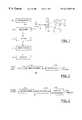
- FIG. 1is a block diagram of an ultrasonic imaging system that incorporates a presently preferred embodiment of this invention.
- FIG. 2is a block diagram of a receiver suitable for use in one embodiment of the system of FIG. 1 .
- FIG. 3is a block diagram of a processor suitable for use in another embodiment of the system of FIG. 1 .
- FIG. 4is a block diagram of a receiver and processor suitable for use in another embodiment of the system of FIG. 1 .
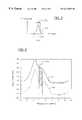
- FIG. 5is a filter response diagram for the filter of FIG. 1 .
- FIG. 6is a magnitude/frequency diagram illustrating receive signals from contrast agent and tissue.
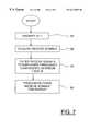
- FIG. 7is a block diagram of a method implemented by the system of FIG. 1 .
- the preferred embodiments described belowexploit the fact that when contrast agents are subjected to medium to high power ultrasound pulses (i.e., ultrasound pulses that provide transmit pressures of at least about 100 kPa at the transmit focus), the frequency spectrum of the second harmonic signal generated by the contrast agents broadens. This broadening is due to the inherent nonlinearity of contrast agents. Harmonic signals generated by nonlinear propagation of the ultrasound signal through tissue do not exhibit similar spectral broadening.
- the embodiments described belowexploit these differences to improve the differentiation of contrast agent from tissue by filtering the receive signal with a receive filter that is centered between the harmonic and fundamental frequencies. Preferably, this filter can also be used to filter out both fundamental and harmonic frequencies of the receive signal such that only those frequencies between the fundamental and harmonic frequencies are passed. This approach can be used for many imaging modes, as for example B-mode harmonic imaging, pulse inversion harmonic imaging, and Doppler harmonic imaging.
- FIG. 1shows a block diagram of a medical diagnostic ultrasonic imaging system 10 that incorporates a preferred embodiment of this invention.
- the system 10includes a transducer probe 12 that is coupled via a transmit/receive switch 14 with both a transmitter 16 and receiver 18 .
- Receive signals acquired by the receiver 18are filtered by a filter 20 and then applied to a processor 22 , where the filtered receive signals are processed for display on a display 24 .
- the transmitter 16applies transmit signals to the transducer probe 12 to form ultrasonic pulses centered about a fundamental frequency f. These pulses are transmitted into an imaged region R which includes both tissue T and contrast agent C.
- tissueis intended broadly to encompass organs, blood, bones, and flesh.
- the signal path that includes the receiver 18 , the filter 20 and the processor 22includes a receive beamformer that applies appropriate delays and/or phasings to achieve the desired steering and focusing.
- the filter 20is centered between the fundamental frequency f and the second harmonic frequency 2 f. This filter can also be used to suppress both the fundamental and harmonic frequency components of the receive signal, retaining only those frequencies in a passband located between the fundamental frequency f and the second harmonic frequency 2 f. This can be accomplished by using a narrow band filter for the filter 20 so that only a small region between the fundamental and second harmonic frequencies is passed.
- filter 20with zeros in the frequency domain at both the fundamental and second harmonic frequencies.
- a filtercan readily be implemented using a digital FIR or IIR filter. Filtering can also be done in the analog domain, and depending upon the application the filter 20 can be placed either upstream or downstream of the receive beamformer in the receive processing path.
- FIG. 2shows one embodiment of the receiver 18 .
- the receiver 18includes an amplifier 26 , a beamformer 28 , and a detector 30 .
- the receiver 18 of FIG. 2is suited for applications in which the filter 20 is positioned downstream of the beamformer 28 .
- FIG. 3shows a processor 22 of another embodiment, in which the beamfomer is positioned downstream of the filter 20 .
- the processor 22includes a beamformer 32 , a detector 34 , and a display processor 36 .
- the display processor 36can be any suitable device for harmonic B-mode imaging, two-pulse imaging, harmonic Doppler imaging, harmonic Doppler two-pulse imaging, or the like.
- FIG. 4shows a receiver 18 and a processor 22 of another embodiment.
- the receiver 18includes an amplifier 26 and a receive beamformer 28 .
- the processor 22includes a detector 34 and a display processor 36 .
- any suitable systemscan be used for the illustrated components.
- the filter 20may be included in the receiver 18 .
- FIG. 5shows a filter response that can be used for the filter 20 .
- the fundamental frequency f and the harmonic frequency 2 fare shown, along with the filter response curve 40 .
- the filter response curve 40peaks at approximately 1.5 f, and that the filter response curve 40 has a passband (as measured at the ⁇ 6 db points) approximately equal to f/2.
- FIG. 6is a magnitude/frequency plot that illustrates the differences between unfiltered receive signals from contrast agent (curve 50 ) and from tissue (curve 52 ).
- the plotted receive signalshave been demodulated to the second harmonic frequency so that 0 MHz corresponds to the second harmonic frequency 2 f and ⁇ 1.75 MHz corresponds to the fundamental frequency f.
- the spectral response curves of FIG. 6were acquired using a broadband transmit pulse such as that typically used in tissue harmonic imaging. The curves were obtained from a single pulse at full power with no baseband filter, using the contrast agent distributed under the trade name Optison.
- the filter 20 of FIG. 1has a filter response such as that shown in FIG. 5 that selectively passes frequency components of the receive signals in the region 54 .
- FIG. 7is a flow chart illustrating one method performed by the system 10 of FIG. 1 .
- the transmitterinsonifies a portion of the imaged region in step 60 with an ultrasound pulse having a peak intensity at a fundamental frequency f.
- receive signalsare acquired by the receiver, and in step 64 these receive signals are filtered to emphasize frequency components disposed between the fundamental frequency f and the second harmonic frequency 2 f.
- Steps 62 and 64can be considered as an example of a step for acquiring backscattered ultrasonic receive signals in a passband that peaks at a frequency disposed between nf and (n+1) f, where n is a positive integer.
- various other techniquescan be used for selectively acquiring backscattered ultrasonic receive signals in the desired passband.
- demodulation techniquespulse inversion techniques, and acoustical filters, as well as electronic or digital filters can be used.
- backscattered ultrasonic receive signalscan be selectively acquired in the desired passband by using a suitable demodulation frequency.
- pulse inversion techniqueswell-known to those skilled in the art can be used to selectively suppress fundamental signals in the selectively acquired backscattered receive signals.
- a transducercan be used which does not efficiently resonate at a harmonic, such as the second harmonic, thereby selectively suppressing second harmonic energy in the selectively acquired receive signals.
- the term “selectively acquiring”is intended broadly to encompass any combination of the methods described above, as well as other methods for ensuring that the receive signals emphasize frequency components in the desired passband while suppressing frequency components in desired regions outside the passband.
- the filtered receive signalis further processed for display.
- the improvements described abovecan be used for B-mode imaging, pulse inversion imaging, power harmonic imaging, or any other imaging method used for contrast agents.
- the methods described abovehave the additional advantage that the effect of tissue motion may be reduced, because tissue motion will appear as signals primarily concentrated at the fundamental and harmonic frequencies, which will be filtered out by the receive filter.
- the transmitter 16 , the receiver 18 , and the transducer probe 12can be any suitable technology, including any suitable technology, including 1, 1.5 and 2 dimensional arrays, which are either linear or curved.
- the filter 20can be implemented as a digital or analog circuit, and it can be positioned at various points in the receive signal path, either upstream or downstream of the beamformer. Demodulation techniques may also be used to implement the filter 20 .
- the filtercan also be implemented as a matched filter, which matches the response of the contrast agent, while treating the response from tissue as well as any noise sources such as electronic noise as a colored noise source. This achieves an optimal filter shape for enhancing signals between the second harmonic and fundamental frequencies.
- Any suitable technologycan be used for the processor 22 , which may operate to process the receive signal for display in any desired display mode, including those discussed above.
- the preferred embodiment described abovehas been designed to selectively acquire receive signals in the region between the first harmonic f and the second harmonic 2 f.
- this passbandis presently preferred, the invention is not limited to this embodiment.
- this inventioncan be used to selectively acquire signals in a passband between any two harmonics nf and (n+1) f, where n is a positive integer.
- the passbandcan be centered between the second and third harmonics ( 2 f and 3 f ).
- a receive signal selectively acquired in a passband between two harmonics as described abovecan be combined with other signals.
- a receive signal selectively acquired in the passband between f and 2 fcan be combined with another selectively acquired receive signal in a passband between the frequencies 2 f and 3 f.
- the term “filter”is intended broadly to include one or more filters. For example, when the filter is positioned downstream of the beamformer, a single filter may be sufficient for an imaging system. Conversely, when the filter is positioned upstream of the beamformer, multiple filters may be used, one associated with each transducer element or group of transducer elements.
- receiver signalis intended broadly to encompass signals at any point in the receive processing path between the transducer and the display.
- individual analog signals from individual transducer elements as well as digital, beamformed signalsare examples of receive signals.
- Coupled withis intended broadly to encompass both elements that are coupled directly together and elements that are coupled indirectly together.
- first and second elementsare said to be coupled with one another whether or not intervening elements are placed in the signal path between the first and second elements.
Landscapes
- Health & Medical Sciences (AREA)
- Life Sciences & Earth Sciences (AREA)
- Engineering & Computer Science (AREA)
- Physics & Mathematics (AREA)
- Animal Behavior & Ethology (AREA)
- Biomedical Technology (AREA)
- Veterinary Medicine (AREA)
- Public Health (AREA)
- General Health & Medical Sciences (AREA)
- Biophysics (AREA)
- Nuclear Medicine, Radiotherapy & Molecular Imaging (AREA)
- Pathology (AREA)
- Radiology & Medical Imaging (AREA)
- Surgery (AREA)
- Heart & Thoracic Surgery (AREA)
- Medical Informatics (AREA)
- Molecular Biology (AREA)
- Radar, Positioning & Navigation (AREA)
- Computer Networks & Wireless Communication (AREA)
- General Physics & Mathematics (AREA)
- Remote Sensing (AREA)
- Nonlinear Science (AREA)
- Hematology (AREA)
- Ultra Sonic Daignosis Equipment (AREA)
Abstract
Description
Claims (22)
Priority Applications (1)
| Application Number | Priority Date | Filing Date | Title |
|---|---|---|---|
| US09/253,089US6213951B1 (en) | 1999-02-19 | 1999-02-19 | Medical diagnostic ultrasound method and system for contrast specific frequency imaging |
Applications Claiming Priority (1)
| Application Number | Priority Date | Filing Date | Title |
|---|---|---|---|
| US09/253,089US6213951B1 (en) | 1999-02-19 | 1999-02-19 | Medical diagnostic ultrasound method and system for contrast specific frequency imaging |
Publications (1)
| Publication Number | Publication Date |
|---|---|
| US6213951B1true US6213951B1 (en) | 2001-04-10 |
Family
ID=22958796
Family Applications (1)
| Application Number | Title | Priority Date | Filing Date |
|---|---|---|---|
| US09/253,089Expired - LifetimeUS6213951B1 (en) | 1999-02-19 | 1999-02-19 | Medical diagnostic ultrasound method and system for contrast specific frequency imaging |
Country Status (1)
| Country | Link |
|---|---|
| US (1) | US6213951B1 (en) |
Cited By (32)
| Publication number | Priority date | Publication date | Assignee | Title |
|---|---|---|---|---|
| US6423007B2 (en)* | 1998-05-26 | 2002-07-23 | Riverside Research Institute | Ultrasonic systems and methods for contrast agent concentration measurement |
| US6461303B2 (en)* | 2000-01-19 | 2002-10-08 | Bjorn Angelsen | Method of detecting ultrasound contrast agent in soft tissue, and quantitating blood perfusion through regions of tissue |
| US6464643B1 (en)* | 2000-10-06 | 2002-10-15 | Koninklijke Philips Electronics N.V. | Contrast imaging with motion correction |
| US20030004414A1 (en)* | 2001-05-31 | 2003-01-02 | Mclaughlin Glen | System and method for phase inversion ultrasonic imaging |
| US6508767B2 (en)* | 2000-02-16 | 2003-01-21 | Koninklijke Philips Electronics N.V. | Ultrasonic harmonic image segmentation |
| US6533727B1 (en)* | 2000-02-11 | 2003-03-18 | Koninklijke Phillips Electronics N.V. | Ultrasonic system and method employing non-integer harmonic echo signals for imaging |
| US6626836B2 (en)* | 2001-04-04 | 2003-09-30 | Siemens Medical Solutions Usa, Inc. | Adaptive signal processing scheme for contrast agent imaging |
| US6640634B2 (en)* | 2000-03-31 | 2003-11-04 | Kabushiki Kaisha Toshiba | Ultrasonic probe, method of manufacturing the same and ultrasonic diagnosis apparatus |
| US20040030251A1 (en)* | 2002-05-10 | 2004-02-12 | Ebbini Emad S. | Ultrasound imaging system and method using non-linear post-beamforming filter |
| US6726630B2 (en) | 2001-11-08 | 2004-04-27 | Kabushiki Kaisha Toshiba | Ultrasound diagnosis apparatus for imaging with a contrast agent |
| US20040127797A1 (en)* | 2002-06-07 | 2004-07-01 | Bill Barnard | System and method for measuring bladder wall thickness and presenting a bladder virtual image |
| US20040267125A1 (en)* | 2003-06-26 | 2004-12-30 | Skyba Danny M. | Adaptive processing of contrast enhanced ultrasonic diagnostic images |
| US20060025689A1 (en)* | 2002-06-07 | 2006-02-02 | Vikram Chalana | System and method to measure cardiac ejection fraction |
| US20060079775A1 (en)* | 2002-06-07 | 2006-04-13 | Mcmorrow Gerald | Systems and methods for quantification and classification of fluids in human cavities in ultrasound images |
| US20070232908A1 (en)* | 2002-06-07 | 2007-10-04 | Yanwei Wang | Systems and methods to improve clarity in ultrasound images |
| US20070276254A1 (en)* | 2002-06-07 | 2007-11-29 | Fuxing Yang | System and method to identify and measure organ wall boundaries |
| US7324165B2 (en)* | 2003-11-20 | 2008-01-29 | Sunplus Technology Co., Ltd. | [Automatic contrast limiting circuit and method thereof with spatial domain infinite impulse response filter] |
| US20080242985A1 (en)* | 2003-05-20 | 2008-10-02 | Vikram Chalana | 3d ultrasound-based instrument for non-invasive measurement of amniotic fluid volume |
| US20080255451A1 (en)* | 2007-04-10 | 2008-10-16 | C.R. Bard, Inc. | Low power ultrasound system |
| US20080262356A1 (en)* | 2002-06-07 | 2008-10-23 | Vikram Chalana | Systems and methods for ultrasound imaging using an inertial reference unit |
| US20090018449A1 (en)* | 2006-02-03 | 2009-01-15 | Koninklijke Philips Electronics, N.V. | Ultrasonic Method and Apparatus for Measuring or Detecting Flow Behavior of a Non-Sinusoidal Periodicity |
| US20090062644A1 (en)* | 2002-06-07 | 2009-03-05 | Mcmorrow Gerald | System and method for ultrasound harmonic imaging |
| US20090112089A1 (en)* | 2007-10-27 | 2009-04-30 | Bill Barnard | System and method for measuring bladder wall thickness and presenting a bladder virtual image |
| US20090264757A1 (en)* | 2007-05-16 | 2009-10-22 | Fuxing Yang | System and method for bladder detection using harmonic imaging |
| US20090299182A1 (en)* | 2005-05-27 | 2009-12-03 | Katsunori Asafusa | Ultrasonic diagnostic apparatus and ultrasonic image display method |
| US20100006649A1 (en)* | 2008-07-11 | 2010-01-14 | Steve Bolton | Secure Ballot Box |
| US20100036252A1 (en)* | 2002-06-07 | 2010-02-11 | Vikram Chalana | Ultrasound system and method for measuring bladder wall thickness and mass |
| US20100036242A1 (en)* | 2007-05-16 | 2010-02-11 | Jongtae Yuk | Device, system and method to measure abdominal aortic aneurysm diameter |
| US20100268082A1 (en)* | 1999-08-20 | 2010-10-21 | Mclaughlin Glen | Ultrasound Imaging System |
| US8308644B2 (en) | 2002-08-09 | 2012-11-13 | Verathon Inc. | Instantaneous ultrasonic measurement of bladder volume |
| CN110575627A (en)* | 2019-09-24 | 2019-12-17 | 黄晶 | Physical mapping device for rapidly acquiring target nerve treatment energy delivery site |
| CN120334567A (en)* | 2025-06-18 | 2025-07-18 | 哈尔滨工业大学(深圳)(哈尔滨工业大学深圳科技创新研究院) | Harmonic imaging and impedance matching echo-PIV measurement method and system |
Citations (10)
| Publication number | Priority date | Publication date | Assignee | Title |
|---|---|---|---|---|
| US5410516A (en) | 1988-09-01 | 1995-04-25 | Schering Aktiengesellschaft | Ultrasonic processes and circuits for performing them |
| US5456257A (en) | 1994-11-23 | 1995-10-10 | Advanced Technology Laboratories, Inc. | Ultrasonic detection of contrast agents |
| US5632277A (en) | 1996-06-28 | 1997-05-27 | Siemens Medical Systems, Inc. | Ultrasound imaging system employing phase inversion subtraction to enhance the image |
| US5706819A (en) | 1995-10-10 | 1998-01-13 | Advanced Technology Laboratories, Inc. | Ultrasonic diagnostic imaging with harmonic contrast agents |
| US5724976A (en) | 1994-12-28 | 1998-03-10 | Kabushiki Kaisha Toshiba | Ultrasound imaging preferable to ultrasound contrast echography |
| US5733527A (en) | 1994-09-28 | 1998-03-31 | Alliance Pharmaceutical Corp. | Methods for harmonic imaging with ultrasound |
| US5740128A (en) | 1995-03-02 | 1998-04-14 | Acuson Corporation | Ultrasonic harmonic imaging system and method |
| US5833613A (en) | 1996-09-27 | 1998-11-10 | Advanced Technology Laboratories, Inc. | Ultrasonic diagnostic imaging with contrast agents |
| US5883614A (en)* | 1995-09-13 | 1999-03-16 | Samsung Electronics Co., Ltd. | Reflection type display utilizing charge coupled devices |
| US6050947A (en)* | 1998-04-20 | 2000-04-18 | General Electric Company | Method and apparatus for harmonic tissue imaging and contrast imaging using coded transmission |
- 1999
- 1999-02-19USUS09/253,089patent/US6213951B1/ennot_activeExpired - Lifetime
Patent Citations (10)
| Publication number | Priority date | Publication date | Assignee | Title |
|---|---|---|---|---|
| US5410516A (en) | 1988-09-01 | 1995-04-25 | Schering Aktiengesellschaft | Ultrasonic processes and circuits for performing them |
| US5733527A (en) | 1994-09-28 | 1998-03-31 | Alliance Pharmaceutical Corp. | Methods for harmonic imaging with ultrasound |
| US5456257A (en) | 1994-11-23 | 1995-10-10 | Advanced Technology Laboratories, Inc. | Ultrasonic detection of contrast agents |
| US5724976A (en) | 1994-12-28 | 1998-03-10 | Kabushiki Kaisha Toshiba | Ultrasound imaging preferable to ultrasound contrast echography |
| US5740128A (en) | 1995-03-02 | 1998-04-14 | Acuson Corporation | Ultrasonic harmonic imaging system and method |
| US5883614A (en)* | 1995-09-13 | 1999-03-16 | Samsung Electronics Co., Ltd. | Reflection type display utilizing charge coupled devices |
| US5706819A (en) | 1995-10-10 | 1998-01-13 | Advanced Technology Laboratories, Inc. | Ultrasonic diagnostic imaging with harmonic contrast agents |
| US5632277A (en) | 1996-06-28 | 1997-05-27 | Siemens Medical Systems, Inc. | Ultrasound imaging system employing phase inversion subtraction to enhance the image |
| US5833613A (en) | 1996-09-27 | 1998-11-10 | Advanced Technology Laboratories, Inc. | Ultrasonic diagnostic imaging with contrast agents |
| US6050947A (en)* | 1998-04-20 | 2000-04-18 | General Electric Company | Method and apparatus for harmonic tissue imaging and contrast imaging using coded transmission |
Non-Patent Citations (3)
| Title |
|---|
| "Harmonic Power Mode Doppler Using Microbubble Contrast Agents: An Improved Method for Small Vessel Flow Imaging," Burns et al., 1994 IEEE Ultrasonic Symposium, pp. 1547-1550, 1994. |
| "Pulse Inversion Doppler: A New Method for Detecting Nonlinear Echoes from Microbubble Contrast Agents," Simpson and Burns, 1997 IEEE Ultrasonic Symposium, 1997. |
| "Simulated Capillary Blood Measurement Using a Nonlinear Ultrasonic Contrast Agent," Schrope et al.; Ultrasonic Imaging, vol. 14, pp. 134-158, 1992. |
Cited By (53)
| Publication number | Priority date | Publication date | Assignee | Title |
|---|---|---|---|---|
| US6423007B2 (en)* | 1998-05-26 | 2002-07-23 | Riverside Research Institute | Ultrasonic systems and methods for contrast agent concentration measurement |
| US20100268082A1 (en)* | 1999-08-20 | 2010-10-21 | Mclaughlin Glen | Ultrasound Imaging System |
| US8764661B2 (en) | 1999-08-20 | 2014-07-01 | Zonare Medical Systems, Inc. | Echolocation data generation |
| US8679018B2 (en) | 1999-08-20 | 2014-03-25 | Zonare Medical Systems, Inc. | Broad-beam imaging |
| US8226561B2 (en) | 1999-08-20 | 2012-07-24 | Zonare Medical Systems, Inc. | Ultrasound imaging system |
| US6461303B2 (en)* | 2000-01-19 | 2002-10-08 | Bjorn Angelsen | Method of detecting ultrasound contrast agent in soft tissue, and quantitating blood perfusion through regions of tissue |
| US6533727B1 (en)* | 2000-02-11 | 2003-03-18 | Koninklijke Phillips Electronics N.V. | Ultrasonic system and method employing non-integer harmonic echo signals for imaging |
| US6508767B2 (en)* | 2000-02-16 | 2003-01-21 | Koninklijke Philips Electronics N.V. | Ultrasonic harmonic image segmentation |
| US6640634B2 (en)* | 2000-03-31 | 2003-11-04 | Kabushiki Kaisha Toshiba | Ultrasonic probe, method of manufacturing the same and ultrasonic diagnosis apparatus |
| US6464643B1 (en)* | 2000-10-06 | 2002-10-15 | Koninklijke Philips Electronics N.V. | Contrast imaging with motion correction |
| US6626836B2 (en)* | 2001-04-04 | 2003-09-30 | Siemens Medical Solutions Usa, Inc. | Adaptive signal processing scheme for contrast agent imaging |
| US7699781B2 (en) | 2001-05-31 | 2010-04-20 | Zonare Medical Systems, Inc. | System for phase inversion ultrasonic imaging |
| US20040158149A1 (en)* | 2001-05-31 | 2004-08-12 | Mclaughlin Glen | System for phase inversion ultrasonic imaging |
| US20080103394A1 (en)* | 2001-05-31 | 2008-05-01 | Mclaughlin Glen | Phase Inversion Ultrasonic Imaging |
| US20030004414A1 (en)* | 2001-05-31 | 2003-01-02 | Mclaughlin Glen | System and method for phase inversion ultrasonic imaging |
| US10222461B2 (en) | 2001-05-31 | 2019-03-05 | Shenzhen Mindray Bio-Medical Electronics Co., Ltd. | Phase inversion ultrasonic imaging |
| US6726630B2 (en) | 2001-11-08 | 2004-04-27 | Kabushiki Kaisha Toshiba | Ultrasound diagnosis apparatus for imaging with a contrast agent |
| US6705993B2 (en) | 2002-05-10 | 2004-03-16 | Regents Of The University Of Minnesota | Ultrasound imaging system and method using non-linear post-beamforming filter |
| US6951540B2 (en) | 2002-05-10 | 2005-10-04 | Regents Of The University Of Minnesota | Ultrasound imaging system and method using non-linear post-beamforming filter |
| US20040030251A1 (en)* | 2002-05-10 | 2004-02-12 | Ebbini Emad S. | Ultrasound imaging system and method using non-linear post-beamforming filter |
| US8221322B2 (en) | 2002-06-07 | 2012-07-17 | Verathon Inc. | Systems and methods to improve clarity in ultrasound images |
| US20070276254A1 (en)* | 2002-06-07 | 2007-11-29 | Fuxing Yang | System and method to identify and measure organ wall boundaries |
| US8221321B2 (en) | 2002-06-07 | 2012-07-17 | Verathon Inc. | Systems and methods for quantification and classification of fluids in human cavities in ultrasound images |
| US20060079775A1 (en)* | 2002-06-07 | 2006-04-13 | Mcmorrow Gerald | Systems and methods for quantification and classification of fluids in human cavities in ultrasound images |
| US20080262356A1 (en)* | 2002-06-07 | 2008-10-23 | Vikram Chalana | Systems and methods for ultrasound imaging using an inertial reference unit |
| US20060025689A1 (en)* | 2002-06-07 | 2006-02-02 | Vikram Chalana | System and method to measure cardiac ejection fraction |
| US20090062644A1 (en)* | 2002-06-07 | 2009-03-05 | Mcmorrow Gerald | System and method for ultrasound harmonic imaging |
| US7819806B2 (en) | 2002-06-07 | 2010-10-26 | Verathon Inc. | System and method to identify and measure organ wall boundaries |
| US20070232908A1 (en)* | 2002-06-07 | 2007-10-04 | Yanwei Wang | Systems and methods to improve clarity in ultrasound images |
| US20040127797A1 (en)* | 2002-06-07 | 2004-07-01 | Bill Barnard | System and method for measuring bladder wall thickness and presenting a bladder virtual image |
| US20100036252A1 (en)* | 2002-06-07 | 2010-02-11 | Vikram Chalana | Ultrasound system and method for measuring bladder wall thickness and mass |
| US8308644B2 (en) | 2002-08-09 | 2012-11-13 | Verathon Inc. | Instantaneous ultrasonic measurement of bladder volume |
| US20080242985A1 (en)* | 2003-05-20 | 2008-10-02 | Vikram Chalana | 3d ultrasound-based instrument for non-invasive measurement of amniotic fluid volume |
| US20040267125A1 (en)* | 2003-06-26 | 2004-12-30 | Skyba Danny M. | Adaptive processing of contrast enhanced ultrasonic diagnostic images |
| US7347821B2 (en) | 2003-06-26 | 2008-03-25 | Koninklijke Philips Electronics N.V. | Adaptive processing of contrast enhanced ultrasonic diagnostic images |
| US7324165B2 (en)* | 2003-11-20 | 2008-01-29 | Sunplus Technology Co., Ltd. | [Automatic contrast limiting circuit and method thereof with spatial domain infinite impulse response filter] |
| US20090299182A1 (en)* | 2005-05-27 | 2009-12-03 | Katsunori Asafusa | Ultrasonic diagnostic apparatus and ultrasonic image display method |
| EP1884195A4 (en)* | 2005-05-27 | 2011-03-30 | Hitachi Medical Corp | Ultrasonograph and ultrasonic image display method |
| US8055036B2 (en) | 2005-05-27 | 2011-11-08 | Hitachi Medical Corporation | Ultrasonic diagnostic apparatus and ultrasonic image display method |
| US20090018449A1 (en)* | 2006-02-03 | 2009-01-15 | Koninklijke Philips Electronics, N.V. | Ultrasonic Method and Apparatus for Measuring or Detecting Flow Behavior of a Non-Sinusoidal Periodicity |
| US9955942B2 (en) | 2006-02-03 | 2018-05-01 | Koninklijke Philips N.V. | Ultrasonic method and apparatus for measuring or detecting flow behavior of a non-sinusoidal periodicity |
| US20080255451A1 (en)* | 2007-04-10 | 2008-10-16 | C.R. Bard, Inc. | Low power ultrasound system |
| US8500645B2 (en) | 2007-04-10 | 2013-08-06 | C. R. Bard, Inc. | Low power ultrasound system |
| US9826960B2 (en) | 2007-04-10 | 2017-11-28 | C. R. Bard, Inc. | Low power ultrasound system |
| US8133181B2 (en) | 2007-05-16 | 2012-03-13 | Verathon Inc. | Device, system and method to measure abdominal aortic aneurysm diameter |
| US20100036242A1 (en)* | 2007-05-16 | 2010-02-11 | Jongtae Yuk | Device, system and method to measure abdominal aortic aneurysm diameter |
| US20090264757A1 (en)* | 2007-05-16 | 2009-10-22 | Fuxing Yang | System and method for bladder detection using harmonic imaging |
| US8167803B2 (en) | 2007-05-16 | 2012-05-01 | Verathon Inc. | System and method for bladder detection using harmonic imaging |
| US20090112089A1 (en)* | 2007-10-27 | 2009-04-30 | Bill Barnard | System and method for measuring bladder wall thickness and presenting a bladder virtual image |
| US20100006649A1 (en)* | 2008-07-11 | 2010-01-14 | Steve Bolton | Secure Ballot Box |
| CN110575627A (en)* | 2019-09-24 | 2019-12-17 | 黄晶 | Physical mapping device for rapidly acquiring target nerve treatment energy delivery site |
| CN110575627B (en)* | 2019-09-24 | 2021-04-06 | 黄晶 | Physical mapping device for rapidly acquiring target nerve treatment energy delivery site |
| CN120334567A (en)* | 2025-06-18 | 2025-07-18 | 哈尔滨工业大学(深圳)(哈尔滨工业大学深圳科技创新研究院) | Harmonic imaging and impedance matching echo-PIV measurement method and system |
Similar Documents
| Publication | Publication Date | Title |
|---|---|---|
| US6213951B1 (en) | Medical diagnostic ultrasound method and system for contrast specific frequency imaging | |
| US6171246B1 (en) | Realtime ultrasonic imaging of perfusion using ultrasonic contrast agents | |
| US6132377A (en) | Medical diagnostic ultrasonic imaging system and method using differential sub-band detection techniques | |
| CA2173841C (en) | Ultrasonic spectral contrast imaging | |
| USRE43048E1 (en) | Ultrasonic diagnostic imaging with harmonic contrast agents | |
| US7985183B2 (en) | Ultrasonic diagnostic equipment and ultrasonic image generation method | |
| EP0913704A3 (en) | Pulse inversion Doppler ultrasonic diagnostic imaging | |
| CN102100567B (en) | Color doppler ultrasonic diagnosis apparatus | |
| MXPA96001754A (en) | Images by spectro ultrason contrast | |
| US6626836B2 (en) | Adaptive signal processing scheme for contrast agent imaging | |
| JP2001299764A (en) | Ultrasonographic instrument | |
| US6783496B2 (en) | Method and apparatus for improving contrast-to-tissue ratio in ultrasound contrast imaging with subharmonic imaging | |
| Kang et al. | A new dynamic complex baseband pulse compression method for chirp-coded excitation in medical ultrasound imaging | |
| EP0885593A3 (en) | Ultrasonic diagnosing apparatus | |
| EP1146351A1 (en) | Ultrasound contrast imaging with double-pulse excitation waveforms | |
| US6290647B1 (en) | Contrast agent imaging with subharmonic and harmonic signals in diagnostic medical ultrasound | |
| JP4269131B2 (en) | Ultrasound contrast drawing device | |
| JP3908348B2 (en) | Ultrasonic diagnostic equipment | |
| Al-Mistarihi et al. | Quadratic pulse inversion ultrasonic imaging (QPI): detection of low-level harmonic activity of microbubble contrast agents [biomedical applications] | |
| Al-Mistarihi et al. | Quadratic pulse inversion ultrasonic imaging (QPI): Analysis and design of quadratic kernel in the frequency domain to reduce tissue component introduced by motion | |
| Al-Mistarihi | Optimization of contrast sensitivity and specificity of quadratic ultrasonic imaging | |
| JP2001204728A (en) | Ultrasound diagnostic equipment | |
| Novell et al. | Exploitation of multi-frequency excitation for contrast agent imaging | |
| Gens et al. | RF lines realignment and stationary echo canceling for microcirculation study: experimental results | |
| JPS63315037A (en) | Ultrasonic continuous wave doppler diagnostic apparatus |
Legal Events
| Date | Code | Title | Description |
|---|---|---|---|
| AS | Assignment | Owner name:ACUSON CORPORATION, CALIFORNIA Free format text:ASSIGNMENT OF ASSIGNORS INTEREST;ASSIGNORS:KRISHNAN, SRIRAM;GARDNER, EDWARD A.;HOLLEY, GREGORY L.;REEL/FRAME:009957/0227;SIGNING DATES FROM 19990428 TO 19990429 | |
| STCF | Information on status: patent grant | Free format text:PATENTED CASE | |
| FEPP | Fee payment procedure | Free format text:PAYOR NUMBER ASSIGNED (ORIGINAL EVENT CODE: ASPN); ENTITY STATUS OF PATENT OWNER: LARGE ENTITY | |
| FPAY | Fee payment | Year of fee payment:4 | |
| FPAY | Fee payment | Year of fee payment:8 | |
| AS | Assignment | Owner name:SIEMENS MEDICAL SOLUTIONS USA, INC.,PENNSYLVANIA Free format text:CHANGE OF NAME;ASSIGNOR:SIEMENS MEDICAL SYSTEMS, INC.;REEL/FRAME:024563/0051 Effective date:20010801 | |
| AS | Assignment | Owner name:SIEMENS MEDICAL SOLUTIONS USA, INC., PENNSYLVANIA Free format text:RE-RECORD TO CORRECT CONVEYING PARTY NAME PREVIOUSLY RECORDED AT REEL 024563 FRAME 0051;ASSIGNORS:ACUSON CORPORATION;ACUSON LLC;ACUSON CORPORATION;SIGNING DATES FROM 20021218 TO 20050926;REEL/FRAME:024651/0673 | |
| FPAY | Fee payment | Year of fee payment:12 |