US6213686B1 - Gimbal for J-Lay pipe laying system - Google Patents
Gimbal for J-Lay pipe laying systemDownload PDFInfo
- Publication number
- US6213686B1 US6213686B1US09/301,695US30169599AUS6213686B1US 6213686 B1US6213686 B1US 6213686B1US 30169599 AUS30169599 AUS 30169599AUS 6213686 B1US6213686 B1US 6213686B1
- Authority
- US
- United States
- Prior art keywords
- jacks
- vertical
- multiplicity
- pipeline
- working table
- Prior art date
- Legal status (The legal status is an assumption and is not a legal conclusion. Google has not performed a legal analysis and makes no representation as to the accuracy of the status listed.)
- Expired - Lifetime
Links
- 230000007246mechanismEffects0.000abstractdescription7
- XLYOFNOQVPJJNP-UHFFFAOYSA-NwaterSubstancesOXLYOFNOQVPJJNP-UHFFFAOYSA-N0.000abstractdescription7
- 238000003466weldingMethods0.000description11
- 230000000712assemblyEffects0.000description10
- 238000000429assemblyMethods0.000description10
- 238000005452bendingMethods0.000description6
- 238000000034methodMethods0.000description6
- 230000008901benefitEffects0.000description5
- 229910000831SteelInorganic materials0.000description4
- 230000008569processEffects0.000description4
- 239000010959steelSubstances0.000description4
- 238000010276constructionMethods0.000description3
- 238000013461designMethods0.000description3
- 238000009434installationMethods0.000description3
- 238000002360preparation methodMethods0.000description3
- 230000008859changeEffects0.000description2
- 238000011161developmentMethods0.000description2
- 238000012986modificationMethods0.000description2
- 230000004048modificationEffects0.000description2
- 230000009286beneficial effectEffects0.000description1
- 239000011248coating agentSubstances0.000description1
- 238000000576coating methodMethods0.000description1
- 230000007812deficiencyEffects0.000description1
- 230000000694effectsEffects0.000description1
- 238000003780insertionMethods0.000description1
- 230000037431insertionEffects0.000description1
- 238000004519manufacturing processMethods0.000description1
- 230000000135prohibitive effectEffects0.000description1
- 230000004044responseEffects0.000description1
Images


Classifications
- F—MECHANICAL ENGINEERING; LIGHTING; HEATING; WEAPONS; BLASTING
- F16—ENGINEERING ELEMENTS AND UNITS; GENERAL MEASURES FOR PRODUCING AND MAINTAINING EFFECTIVE FUNCTIONING OF MACHINES OR INSTALLATIONS; THERMAL INSULATION IN GENERAL
- F16L—PIPES; JOINTS OR FITTINGS FOR PIPES; SUPPORTS FOR PIPES, CABLES OR PROTECTIVE TUBING; MEANS FOR THERMAL INSULATION IN GENERAL
- F16L1/00—Laying or reclaiming pipes; Repairing or joining pipes on or under water
- F16L1/12—Laying or reclaiming pipes on or under water
- F16L1/16—Laying or reclaiming pipes on or under water on the bottom
- F16L1/18—Laying or reclaiming pipes on or under water on the bottom the pipes being S- or J-shaped and under tension during laying
- F16L1/19—Laying or reclaiming pipes on or under water on the bottom the pipes being S- or J-shaped and under tension during laying the pipes being J-shaped
- B—PERFORMING OPERATIONS; TRANSPORTING
- B63—SHIPS OR OTHER WATERBORNE VESSELS; RELATED EQUIPMENT
- B63B—SHIPS OR OTHER WATERBORNE VESSELS; EQUIPMENT FOR SHIPPING
- B63B35/00—Vessels or similar floating structures specially adapted for specific purposes and not otherwise provided for
- B63B35/03—Pipe-laying vessels
- F—MECHANICAL ENGINEERING; LIGHTING; HEATING; WEAPONS; BLASTING
- F16—ENGINEERING ELEMENTS AND UNITS; GENERAL MEASURES FOR PRODUCING AND MAINTAINING EFFECTIVE FUNCTIONING OF MACHINES OR INSTALLATIONS; THERMAL INSULATION IN GENERAL
- F16L—PIPES; JOINTS OR FITTINGS FOR PIPES; SUPPORTS FOR PIPES, CABLES OR PROTECTIVE TUBING; MEANS FOR THERMAL INSULATION IN GENERAL
- F16L1/00—Laying or reclaiming pipes; Repairing or joining pipes on or under water
- F16L1/12—Laying or reclaiming pipes on or under water
- F16L1/20—Accessories therefor, e.g. floats or weights
- F16L1/225—Stingers
- F—MECHANICAL ENGINEERING; LIGHTING; HEATING; WEAPONS; BLASTING
- F16—ENGINEERING ELEMENTS AND UNITS; GENERAL MEASURES FOR PRODUCING AND MAINTAINING EFFECTIVE FUNCTIONING OF MACHINES OR INSTALLATIONS; THERMAL INSULATION IN GENERAL
- F16L—PIPES; JOINTS OR FITTINGS FOR PIPES; SUPPORTS FOR PIPES, CABLES OR PROTECTIVE TUBING; MEANS FOR THERMAL INSULATION IN GENERAL
- F16L1/00—Laying or reclaiming pipes; Repairing or joining pipes on or under water
- F16L1/12—Laying or reclaiming pipes on or under water
- F16L1/20—Accessories therefor, e.g. floats or weights
- F16L1/235—Apparatus for controlling the pipe during laying
Definitions
- This inventionrelates generally to laying underwater pipelines in relatively deep water using a J-Lay method from a floating vessel and, more particularly, to installing underwater pipelines on the seabed and/or connecting the same to floating terminals at the surface.
- Subsea pipelineshave most often been laid on the ocean floor by connection of welding on the deck of a barge, lowering off the back of the barge down a stinger, and then laying on the ocean floor.
- the curve down off the barge and then reverse curve onto the ocean floorgives a “S” bend in the pipeline during the lay process.
- the stingerallows the pipeline and its associated weight to be curved down toward the ocean floor without kinking or damaging the pipeline. As water depths become greater; the size, weight, and cost of the stinger become prohibitive.
- J-Laying pipeIn deeper water, it is advantageous to connect the pipeline vertically and lower it directly into the water, with a single bend at the ocean floor. This gives the shape of a “J” for a system known as J-Laying pipe.
- the “J”cannot be vertical at the top, but rather must have an angle with a horizontal component to be able to pull horizontal tension on the pipeline as it is being laid onto the ocean floor. If it does not have horizontal tension, it will buckle as it is laid on the ocean floor and be damaged beyond use.
- the fixed angle towersrequire that the vessel drive along the pipe route in order to lay the pipeline.
- the vesselswill not have the power to hold course when being broadsided by the weather but could hold course if it could face the weather. In other cases, the stability of the vessel is simply better when facing the weather.
- Rigidly installed, vertical towersengender a number of problems caused by an inability to respond in real time to the dynamic forces encountered during pipe laying operations. For instance, welding and assembly operations are performed at the working floor on pipe with a substantial imposed moment. Other deficiencies include the fact that they do not allow: 1) control of the bending stress and tension within the pipe string as it is deployed in an arc to the sea bed; 2) the laying vessel to weather vane or rotate about the pipe and thereby prevent torsional wind-up of the pipe string; and 3) precise control of the pipe lay envelope. Further, current J-Lay tower designs omit any means for precise and accurate alignment of the pipe string and new pipe joints during the welding process.
- stinger designshave a problem in that the internal geometry of the stinger is usually fixed at the diameter of the pipe string being deployed. In order to allow the passage of large diameter packages integrated into the pipe string, the stinger must be dismantled or removed from around the hanging pipe string. Additionally, such stingers only act as guide conduits for the pipe and do not stabilize, i.e., control the alignment of, the pipe as it emerges from the weld floor.
- the present inventionis directed to overcoming, or at least reducing the effects of, one or more of the problems set forth above.
- the object of this inventionis to provide a tower which can be gimbaled to different angles while facilitating the welding of pipeline sections for laying pipelines on the ocean floor from a floating vessel.
- a second object of this inventionis to provide jacking mechanisms which can be used to gimbal the tower.
- Another object of this inventionis to provide means to separate the forces of the pipelines to be supported into horizontal and vertical components and provide separate mechanisms to support the horizontal and vertical components.
- Another object of this inventionis to provide means for the support of the pipeline while lowering it as new sections are added by welding.
- FIG. 1illustrates the apparatus for assembling and deploying pipe string underwater, mounted on the rear of a floating vessel and deploying a pipeline.
- FIG. 2shows a section of pipeline which has a shoulder at the upper end for handling and weld preparations at each end.
- FIG. 3shows a half section enlargement of the shoulder at the top of the section of pipeline of FIG. 2 .
- FIG. 4shows a half section of a double collar which is used to wrap around the shoulder of FIG. 3 for the purpose of providing two independent shoulders for handling.
- FIG. 5shows a top view of the double collar of FIG. 4 .
- FIG. 6shows a more detailed perspective view of the apparatus.
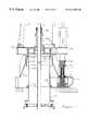
- FIG. 7is a partial cross-sectional, side view of part of the tower system.
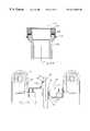
- FIG. 8is a front view of the clamp assembly which will engage and lower the double collar and therefore the pipeline.
- FIG. 9shows a top view of the clamp assembly of FIG. 8 with the doors open for accepting the double collar.
- FIG. 10shows the clamp assembly of FIG. 9 with the doors closed around the double collar and pipeline.
- FIG. 11shows a half section of the swivel bearing
- FIG. 12shows the clamp assembly at the top of its stroke between the main drums or pulleys, with the double collar engaging the pipeline and clamp shoulder on the right side of the centerline and also the swivel bearing inserted between the double collar and the clamp shoulder on the left side of the centerline
- FIG. 13is a half section view of a screw jack as employed in the articulating joint.
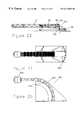
- FIG. 14illustrates the stinger of the apparatus which minimizes the bending radius of the exiting pipeline.
- FIG. 15illustrates the erector system of the embodiment.
- FIG. 16illustrates the tongs which are used to handle the pipeline.
- FIG. 17illustrates tongs which are used to handle the pipeline, having rollers rather than pads to allow moving the tongs along the pipe section under load.
- FIG. 18shows a partial section through the weld alignment and placement system.
- FIG. 19shows a half section through section 18 .
- FIG. 20illustrates a bootstrap mechanism as may be used in some alternative embodiments to erect the articulated tower.
- FIG. 21illustrates a top view of FIG. 20 .
- FIG. 22illustrates the installation of the bootstrap mechanism of FIGS. 20 and 21 onto the tower.
- the j-lay tower 10is shown on a floating vessel 12 in a body of water 14 with a pipeline 16 extending below the j-lay tower 10 around a bend 18 and onto the ocean floor 20 .
- the j-lay tower 10is shown with a mast 21 including a lower section 22 , a middle section 24 , and an upper section 26 ; a working table 28 ; and a skid 30 .
- a new pipeline section 32is shown on the erector 34 with cable 36 attached for pulling the erector up to the mast sections.
- Jib cranes 38 and 40are provided for handling of the new pipe section 32 up to the erector 34 .
- the toweris inclined at an angle convenient to the laying of the pipeline.
- Jack assemblies, 42 as will be described later,assist in the changing of the tower angle as required.
- Stinger 44provides internal rollers whose inner diameter provide a curvature to prevent overbending of the pipeline.
- the preferred running styleis with the tower perfectly aligned to the pipeline, while using the angle gained around the curvature of the stinger as a margin of error if unforeseen events occur.
- a pipe section 32shows upper weld preparation 50 , lower weld preparation 52 , shoulder 54 , and buttweld 56 .
- Buttweld 56is made on shore to attach the j-lay collar 58 to a plain section of pipe so that the plain section of pipe can be conveniently handled offshore.
- FIG. 3an enlarged view of the j-lay collar 58 is shown.
- a double collar 60is shown which is made in two halves and can be wrapped around the shoulder 54 on j-lay collar 58 . After welding a new section of pipeline to the pipeline 16 hanging from the tower, two shoulders are required as will be discussed later.
- the double collar 60engages the j-lay collar with a groove 62 and provides an upper shoulder 64 and a lower shoulder 66 .
- Hinge 68allows the double collar 60 to open and latch 70 holds it closed during operations.
- Handles 72are provided for handling.
- FIG. 5a top view of the double collar 60 is shown.
- FIG. 6a perspective view of the apparatus is shown with the erector 34 shown partially raised toward the mast sections 22 , 24 , and 26 .
- Main cylinders 80with cables 82 over drums 84 are used to lift the travelling table 86 to power the system.
- Outriggers 88are used to distribute the weight of the system over a large deck area.
- Notch 90 in the top of the upper mast section 26allows longer sections of new pipe to be added to the pipeline by having intermediate j-lay collars in place.
- Bushings 92are provided for the support of the pipeline at the working table 28 .
- FIG. 7a half section thru the working table 28 area is shown with the 62′′ bowl 100 forming the internal portion of the working table 28 , the 62′′ split bushing 102 landed in the 62′′ bowl 100 , the 26′′ split bushing 104 landed on the 62′′ split bushing 102 , and the double collar 60 landed on the 26′′ bushing 104 , in turn supporting the pipeline 16 upon shoulder 54 .
- a stinger swivel 112Attached to the bottom of 62′′ bowl 100 by bolts 110 is a stinger swivel 112 including an upper flange 114 , a lower flange 116 , a central barrel 118 , and a spherical section 120 .
- the spherical section 120fits closely within a cylindrical bore 122 which is attached by conical member 124 to skid 30 by welding.
- Spherical section 120has a spherical center 126 .
- Bolts 130connect stinger 44 to the lower flange 116 of the stinger swivel 112 , and will be further described later.
- Each of three Jack assemblies 42includes a spherical center 132 .
- Each of the three jack assembly spherical centers 132 and the stinger swivel spherical center 126are approximately in a common plane.
- Three jack assembliesare shown as they can be used at the bottom of their stroke for a horizontal working table, and only be extended up for tilting the table.
- An alternative embodimentwould be to use 2 jacks and one rigid leg. This would simplify the construction from the fact that only two powered jacks would be required, but would complicate it in that the jacks would need to start in mid stroke for a horizontal plane and would each require a longer stroke.
- the working table 28 , stinger swivel 112 , and the jack assemblies 42are shown in their lowest position with respect to the skid 30 . If any one of the three jack assemblies 42 are actuated to move upwardly, the portion of the working table 28 above that jack assembly will be raised, tilting the working table and all parts attached to the working table including the mast, stinger swivel, and stinger.
- the mastis intended to operate in a near vertical mode, i.e. +/ ⁇ 15 to 25 degrees from vertical.
- the jack assemblies 42are tall and slender and adapted to support a vertical load, but not well adapted to support a horizontal load.
- a slip plane 140is established in the jack assembly 42 to prevent a horizontal or side load from being imparted into the jack assemblies 42 .
- the jack assemblies 42having little ability to support a horizontal force, the tendency to move horizontally is blocked by the engagement of the spherical section 120 with the cylindrical bore 122 .
- the cylindrical bore 122having no capacity to support a vertical load, the components of force are divided into the vertical force to the jack assemblies and the horizontal force to the stinger swivel.
- Mast 21is connected to the working table 28 by a pivot pin 142 and a locking pin 144 , which will be discussed later in conjunction with erecting the mast.
- FIG. 8a front view is seen of the travelling table 86 showing the main clamp section 150 , two doors 152 and 154 , and two wing portions 156 and 158 with lower bearing surfaces 160 and 162 .
- the travelling table 86itself is fabricated of a top plate 164 , a bottom plate 166 , a left plate 168 , a right plate 170 , a left guide 172 and a right guide 174 .
- Wing portions 156 and 158bear and support on left plate 168 and right plate 170 respectively.
- doors 152 and 154are swung open to allow the insertion of the pipeline.
- the doors 152 and 154are closed as if to accept the pipe for support, with pin 180 installed to keep the doors closed.
- Hinge pins 182 and 184allow for the opening of the doors 152 and 154 and cylinders 186 and 188 power the movement of the doors.
- Cylinders 190 and 192provide means to slide the clamp assembly backwards and forwards to allow the shoulder 194 to be moved away from or under the shoulder on the double collar 60 . (See FIG. 12)
- Plates 196 and 198provide attachment holes for the cables 82 as seen in FIG. 6 to lift the travelling table 86 and therefore the pipeline 16 .
- the holes in plates 196 and 198are a substantial distance apart which is difficult to bridge safely by a single member because of the high moment generated by the overall distance.
- the method of this constructionallows the main clamp section 150 to only be required to bridge between the support of plates 168 and 170 , and therefore substantially reduce stresses on the parts generated by this first moment.
- the second moment established in the travelling tableis a function of the distance between the support of plate 168 and 170 areas and the holes for the cables on the outside.
- the stress in upper plate 164 and lower plate 166is generated by the second moment in which is again substantially smaller than the moment which would be generated by similar forces across the full distances from plates 196 and 198 .
- the division of distancesprovides lower stresses than might otherwise be seen and allows a workable system at lower overall cost and weight.
- a rotating bushing 200is shown which allows the rotation of the pipeline 16 relative to the floating vessel 12 .
- the unitis made of a lower non-rotating body 202 , an upper rotating body 204 , several low friction bearing rings 206 , and a retaining screws 208 .
- the travelling tableis shown near its uppermost position between the drums 84 .
- a double collar 60is shown around the j-lay collar 58 , with the upper shoulder 64 landed on the shoulder 194 within the main clamp section 150 .
- the left side of the centerlineshows the rotating bushing 200 landed over the end of the pipeline 16 and the double collar 60 clamped around the j-lay collar 58 .
- Picking up on the travelling table 86causes the weight of the pipeline 16 to be carried on the low friction bearings 206 within the rotating bushing 200 , conveniently allowing the pipeline 16 to be rotated relative to the floating vessel 12 .
- a jack assembly 42is shown in detail.
- the upper endhas a flange 210 for interconnecting to the bottom of the working table 28 and a spherical section 212 around the spherical center 132 as previously discussed.
- a slip plane 140is established by having upper and lower low friction bearings 214 and 216 and a flange 218 positioned between the bearings.
- the flange 218is a part of a male threaded shaft 220 which is rotated by gear 234 to move the upper portion of the jack assembly 42 up and down.
- a square shaft 226engages a square hole 228 and causes the male threaded shaft 220 to be rotated in response to the input of motors (not shown), which drive worm gears 230 and 232 , wheel gear 234 , and interconnecting pieces 236 .
- Internally threaded base 240utilizes bolts 242 to secure the jack assembly 42 to skid 30 .
- stinger 44is shown comprised of six stations 250 , 252 , 254 , 256 , 258 , and 260 which include multiple rollers 262 to restrict the bending radius of the pipeline. All stations are equipped with cylinders 264 to swing the arms 266 and rollers 262 of the stations out of the bore to allow large object to pass through the stinger and into the bore to provide the preferred bending radius. Stations 250 and 252 have four arms 266 at 90° apart. Two adjacent arms 266 fold down to a fixed position at a distance from the centerline of the stinger approximately equal to the radius of the pipeline 16 . The other two arms 266 include cylinders 264 which press the rollers 262 on the arms 266 tightly against the pipeline 16 after being folded into the bore of the stinger 44 . In this manner, the pipeline 16 is immobilized against movement during the welding process.
- Each of the additional stations 254 - 260have arms 266 which fold down to a fixed position of a progressively larger radius from top to bottom.
- a camera 270 or similar viewing deviceis installed at the bottom of the stinger 44 .
- Erector boxes 271 and 272provide clamps 273 and 274 for securing new pipeline section 32 to erector 34 . Additionally, erector boxes 271 and 272 may provide rollers 275 and 276 for supporting new pipe section 32 and the rollers may be powered with hydraulic motors or the such like to rotate the new pipe section 32 . This can be beneficial when the new pipe sections are not perfectly round and the out of roundness of one joint is desired to be matched with the out of roundness of the next joint to simplify the welding process.
- the erector 34is attached to the working table 28 by hinge 280 .
- Item 282is the erector 34 shown pulled partially to the mast by cable 284 .
- the erector 34 and new pipe section 32is represented fully up in the mast by item 286 .
- the working table 28can be gimbaled up to 15° in any direction by operation of the jack assemblies 42 , the required position of the erector 34 to properly engage the mast sections 22 , 24 , and 26 is difficult to predict.
- hinging the erector on the working table itself at 280the erector will automatically track the position of the mast sections and automatically be correctly engaged when erected to the position shown at 286 .
- a centralizer 287 and a straightener 288are shown which cooperate with the travelling table 86 in making the weld between the current pipeline 16 and the new pipeline section 32 at 289 . These will be discussed further detail later.
- tongs 290are shown which are utilized by the jib cranes 38 and 40 to handle the new pipe sections 32 .
- the tongshave pads 292 to engage the pipeline while protecting the coating, a link 294 at the top which when pulled causes linkages 296 to close, automatically locking onto the new pipe section 32 , and a hydraulic cylinder 298 to release the tongs 290 when desired.
- rollers 302which can move along the new pipeline section 32 to accommodate the arcuate swing of the jib cranes.
- FIG. 18a partial section thru a centralizer 287 is shown which is used to align the bottom of the new pipeline section 32 near the bottom with the top of the already welded pipeline in at the working table at 296 (see FIG. 15 ).
- Four hydraulic cylinders 310 , 312 , 314 , and 316press on pivot arms 320 , 322 , 324 , and 326 to load rollers 330 , 332 , 334 , and 336 against new pipe section 32 .
- the lower end of new pipeline section 32can be properly aligned with the top of the pipeline 16 for welding.
- a similar device referred to as a straightener 288is positioned near the center of the new pipeline section 32 to push the center of the new pipeline section while the upper and lower ends are restrained by the travelling table 86 and the centralizer 287 respectively. This imparts a bending moment to the new pipeline section 32 which can promote better angular alignment of the faces of the ends of the pipe sections for welding.
- FIG.19a half section of the straightener 287 or centralizer 288 is shown with the cylinder 340 for folding the units up and out of the way to allow passage of the travelling table 86 when required.
- bootstrap mechanism 350is shown which is bolted to the top of the working table 28 with bolts 352 , and provides a heavy chain 354 attached to a dummy double collar 356 . As shown, the heavy chain 354 is wrapped around a reinforced curved member 358 .
- the bootstrap mechanism 350is installed on the working table 28 , the mast 21 is attached at pivot pin 142 and the dummy double collar 356 is connected into the travelling table 86 .
- the cablespull on the travelling table 86 , which pulls on the dummy double collar 356 , which pulls on the heavy chain 354 , which pulls on the floor of the working table 28 .
- the mast 21Rather than lifting the working table (lifting oneself by your bootstraps), the mast 21 itself is erected with its attachments. In this way the power of the system can be used to advantage to self erect itself when adequate cranes are not available.
Landscapes
- Engineering & Computer Science (AREA)
- General Engineering & Computer Science (AREA)
- Mechanical Engineering (AREA)
- Chemical & Material Sciences (AREA)
- Combustion & Propulsion (AREA)
- Ocean & Marine Engineering (AREA)
- Supports For Pipes And Cables (AREA)
Abstract
Description
Claims (20)
Priority Applications (1)
| Application Number | Priority Date | Filing Date | Title |
|---|---|---|---|
| US09/301,695US6213686B1 (en) | 1998-05-01 | 1999-04-29 | Gimbal for J-Lay pipe laying system |
Applications Claiming Priority (2)
| Application Number | Priority Date | Filing Date | Title |
|---|---|---|---|
| US8396498P | 1998-05-01 | 1998-05-01 | |
| US09/301,695US6213686B1 (en) | 1998-05-01 | 1999-04-29 | Gimbal for J-Lay pipe laying system |
Publications (1)
| Publication Number | Publication Date |
|---|---|
| US6213686B1true US6213686B1 (en) | 2001-04-10 |
Family
ID=26769971
Family Applications (1)
| Application Number | Title | Priority Date | Filing Date |
|---|---|---|---|
| US09/301,695Expired - LifetimeUS6213686B1 (en) | 1998-05-01 | 1999-04-29 | Gimbal for J-Lay pipe laying system |
Country Status (1)
| Country | Link |
|---|---|
| US (1) | US6213686B1 (en) |
Cited By (30)
| Publication number | Priority date | Publication date | Assignee | Title |
|---|---|---|---|---|
| US6398457B2 (en)* | 1998-05-01 | 2002-06-04 | Oil States Industries, Inc. | Pipe weld alignment system and method of operation |
| US6435771B1 (en) | 2000-11-27 | 2002-08-20 | Benton F. Baugh | Method for attaching subsea manifold to pipeline tee |
| US20030221842A1 (en)* | 2002-06-03 | 2003-12-04 | Hayes Kevin W. | Handling and assembly equipment and method |
| WO2004015321A1 (en)* | 2002-08-02 | 2004-02-19 | Stolt Offshore S.A. | Method of and apparatus for interconnecting lined pipes |
| US6746182B2 (en)* | 2001-07-27 | 2004-06-08 | Abb Vetco Gray Inc. | Keel joint arrangements for floating platforms |
| US6776560B2 (en) | 2002-06-13 | 2004-08-17 | Mark Moszkowski | Flex J-Lay tower |
| US20050100413A1 (en)* | 2003-10-06 | 2005-05-12 | Baugh Benton F. | Roto-erector for J-Lay pipelaying system |
| US6910848B1 (en)* | 1998-05-01 | 2005-06-28 | Benton F. Baugh | Erector for J-Lay pipe laying system |
| WO2005085692A1 (en) | 2004-03-10 | 2005-09-15 | Gusto Engineering B.V. | Light-weight versatile j-lay system |
| US20050284638A1 (en)* | 2004-06-28 | 2005-12-29 | Riggs David C | Method for inspection and repair of a flexible joint |
| US20060275102A1 (en)* | 2003-03-25 | 2006-12-07 | Willis Stewart K | Apparatus and methods for laying of elongate articles from a vessel |
| GB2460671A (en)* | 2008-06-04 | 2009-12-09 | Subsea 7 Ltd | Apparatus and method for reducing torsion in a pipeline when laying pipe on the sea floor |
| GB2462656A (en)* | 2008-08-15 | 2010-02-17 | Subsea 7 Ltd | Apparatus and method for reducing torsion in a pipeline when laying pipe on the sea floor |
| US20100092244A1 (en)* | 2007-02-05 | 2010-04-15 | Stewart Willis | Method and apparatus for laying a marine pipeline |
| US20100119307A1 (en)* | 2007-02-13 | 2010-05-13 | Smb Atlantia, Inc. | System usable with a pipe laying vessel |
| US7909538B2 (en) | 2005-06-29 | 2011-03-22 | Acergy Uk Limited | Pipe laying vessel and methods of operation thereof |
| US20110103894A1 (en)* | 2008-04-29 | 2011-05-05 | Itrec B.V. | Marine pipelaying system and method |
| GB2476824A (en)* | 2010-01-11 | 2011-07-13 | Acergy Uk Ltd | Improvements relating to welding and other operations during J-lay pipelaying |
| US8230913B2 (en) | 2001-01-16 | 2012-07-31 | Halliburton Energy Services, Inc. | Expandable device for use in a well bore |
| US20130004240A1 (en)* | 2010-03-18 | 2013-01-03 | Pionetti Francois-Regis | Method for laying a submarine line on the seabed |
| US20140037384A1 (en)* | 2012-08-06 | 2014-02-06 | Jesper Moeller | Cable hang-off arrangement |
| USRE45011E1 (en) | 2000-10-20 | 2014-07-15 | Halliburton Energy Services, Inc. | Expandable tubing and method |
| US9079643B2 (en) | 2010-01-13 | 2015-07-14 | Saipem S.P.A. | Undersea pipe-laying |
| CN104854388A (en)* | 2012-12-12 | 2015-08-19 | 单浮标系泊有限公司 | Sbm schiedam b v |
| CN105277357A (en)* | 2015-11-25 | 2016-01-27 | 中国海洋石油总公司 | Test apparatus for simulating disposal recovery process of J type pipe-laying ship |
| CN105605315A (en)* | 2016-03-15 | 2016-05-25 | 哈尔滨工程大学 | Three-joint pipe collar type J-lay system |
| CN105972378A (en)* | 2016-06-26 | 2016-09-28 | 杨越 | Connecting and receiving component for maintaining unmanned ship borne pipeline |
| WO2018050877A1 (en) | 2016-09-16 | 2018-03-22 | Ihc Engineering Business Limited | System, apparatus and method |
| US10619763B2 (en) | 2018-02-06 | 2020-04-14 | Benton Frederick Baugh | Subsea pipeline connector method |
| CN114871104A (en)* | 2022-05-31 | 2022-08-09 | 河南黄河旋风股份有限公司 | Diamond model selection machine model selection disc with space attitude adjusting device |
Citations (9)
| Publication number | Priority date | Publication date | Assignee | Title |
|---|---|---|---|---|
| FR1532570A (en)* | 1967-05-31 | 1968-07-12 | Grands Travaux De Marseille Sa | Method and device for attenuating the effect of swell during the pure tension laying of subsea pipelines |
| US3581506A (en)* | 1968-12-31 | 1971-06-01 | Pan American Petroleum Corp | Laying pipeline in deep water |
| US3602175A (en)* | 1969-07-02 | 1971-08-31 | North American Rockwell | Oil production vessel |
| EP0020257A1 (en)* | 1979-06-01 | 1980-12-10 | Gaz De France | Apparatus for laying a submarine pipeline J-wise |
| US4324194A (en)* | 1976-12-10 | 1982-04-13 | Hydra-Rig, Inc. | Stabilized hoist rig for deep ocean mining vessel |
| US4347029A (en)* | 1979-12-28 | 1982-08-31 | Deepsea Ventures, Inc. | Pipe transfer system |
| US5421675A (en)* | 1993-11-18 | 1995-06-06 | Mcdermott International, Inc. | Apparatus for near vertical laying of pipeline |
| US5458441A (en)* | 1991-04-23 | 1995-10-17 | Shell Oil Company | Pipe section for installation into a subsea pipeline |
| US5464307A (en)* | 1993-12-29 | 1995-11-07 | Mcdermott International, Inc. | Apparatus for near vertical laying of pipeline |
- 1999
- 1999-04-29USUS09/301,695patent/US6213686B1/ennot_activeExpired - Lifetime
Patent Citations (10)
| Publication number | Priority date | Publication date | Assignee | Title |
|---|---|---|---|---|
| FR1532570A (en)* | 1967-05-31 | 1968-07-12 | Grands Travaux De Marseille Sa | Method and device for attenuating the effect of swell during the pure tension laying of subsea pipelines |
| GB1178219A (en)* | 1967-05-31 | 1970-01-21 | Grands Travaux De Marseille Sa | Improvements in or relating to a System for Laying of Submarine Pipe Lines |
| US3581506A (en)* | 1968-12-31 | 1971-06-01 | Pan American Petroleum Corp | Laying pipeline in deep water |
| US3602175A (en)* | 1969-07-02 | 1971-08-31 | North American Rockwell | Oil production vessel |
| US4324194A (en)* | 1976-12-10 | 1982-04-13 | Hydra-Rig, Inc. | Stabilized hoist rig for deep ocean mining vessel |
| EP0020257A1 (en)* | 1979-06-01 | 1980-12-10 | Gaz De France | Apparatus for laying a submarine pipeline J-wise |
| US4347029A (en)* | 1979-12-28 | 1982-08-31 | Deepsea Ventures, Inc. | Pipe transfer system |
| US5458441A (en)* | 1991-04-23 | 1995-10-17 | Shell Oil Company | Pipe section for installation into a subsea pipeline |
| US5421675A (en)* | 1993-11-18 | 1995-06-06 | Mcdermott International, Inc. | Apparatus for near vertical laying of pipeline |
| US5464307A (en)* | 1993-12-29 | 1995-11-07 | Mcdermott International, Inc. | Apparatus for near vertical laying of pipeline |
Non-Patent Citations (2)
| Title |
|---|
| "New Modular J-Lay System Designed for Deepwater Projects", Pipe Line and Gas magazine, Apr. 1999.* |
| Radoil Flyer, 1 page, published 1998.* |
Cited By (55)
| Publication number | Priority date | Publication date | Assignee | Title |
|---|---|---|---|---|
| US6398457B2 (en)* | 1998-05-01 | 2002-06-04 | Oil States Industries, Inc. | Pipe weld alignment system and method of operation |
| US6910848B1 (en)* | 1998-05-01 | 2005-06-28 | Benton F. Baugh | Erector for J-Lay pipe laying system |
| USRE45099E1 (en) | 2000-10-20 | 2014-09-02 | Halliburton Energy Services, Inc. | Expandable tubing and method |
| USRE45244E1 (en) | 2000-10-20 | 2014-11-18 | Halliburton Energy Services, Inc. | Expandable tubing and method |
| USRE45011E1 (en) | 2000-10-20 | 2014-07-15 | Halliburton Energy Services, Inc. | Expandable tubing and method |
| US6435771B1 (en) | 2000-11-27 | 2002-08-20 | Benton F. Baugh | Method for attaching subsea manifold to pipeline tee |
| US8230913B2 (en) | 2001-01-16 | 2012-07-31 | Halliburton Energy Services, Inc. | Expandable device for use in a well bore |
| US6746182B2 (en)* | 2001-07-27 | 2004-06-08 | Abb Vetco Gray Inc. | Keel joint arrangements for floating platforms |
| US20030221842A1 (en)* | 2002-06-03 | 2003-12-04 | Hayes Kevin W. | Handling and assembly equipment and method |
| US7055609B2 (en)* | 2002-06-03 | 2006-06-06 | Schlumberger Technology Corporation | Handling and assembly equipment and method |
| US6776560B2 (en) | 2002-06-13 | 2004-08-17 | Mark Moszkowski | Flex J-Lay tower |
| GB2407629B (en)* | 2002-08-02 | 2005-12-21 | Stolt Offshore Sa | Method of and apparatus for interconnecting lined pipes |
| US20050246883A1 (en)* | 2002-08-02 | 2005-11-10 | Alliot Vincent M G | Method of and apparatus for interconnecting lined pipes |
| GB2407629A (en)* | 2002-08-02 | 2005-05-04 | Stolt Offshore Sa | Method of and apparatus for interconnecting lined pipes |
| WO2004015321A1 (en)* | 2002-08-02 | 2004-02-19 | Stolt Offshore S.A. | Method of and apparatus for interconnecting lined pipes |
| US7908732B2 (en) | 2002-08-02 | 2011-03-22 | Stolt Offshore S.A. | Method of and apparatus for interconnecting lined pipes |
| US20060275102A1 (en)* | 2003-03-25 | 2006-12-07 | Willis Stewart K | Apparatus and methods for laying of elongate articles from a vessel |
| US7806628B2 (en) | 2003-03-25 | 2010-10-05 | Acergy Uk Limited | Apparatus and methods for laying of elongate articles from a vessel |
| US20050100413A1 (en)* | 2003-10-06 | 2005-05-12 | Baugh Benton F. | Roto-erector for J-Lay pipelaying system |
| WO2005085692A1 (en) | 2004-03-10 | 2005-09-15 | Gusto Engineering B.V. | Light-weight versatile j-lay system |
| US20050284638A1 (en)* | 2004-06-28 | 2005-12-29 | Riggs David C | Method for inspection and repair of a flexible joint |
| US7472755B2 (en)* | 2004-06-28 | 2009-01-06 | Riggs David C | Method for inspection and repair of a flexible joint |
| US7909538B2 (en) | 2005-06-29 | 2011-03-22 | Acergy Uk Limited | Pipe laying vessel and methods of operation thereof |
| US20100092244A1 (en)* | 2007-02-05 | 2010-04-15 | Stewart Willis | Method and apparatus for laying a marine pipeline |
| US8807872B2 (en)* | 2007-02-05 | 2014-08-19 | Technip France Sa | Method and apparatus for laying a marine pipeline |
| US20100119307A1 (en)* | 2007-02-13 | 2010-05-13 | Smb Atlantia, Inc. | System usable with a pipe laying vessel |
| US8366352B2 (en) | 2007-02-13 | 2013-02-05 | Sbm Atlantia, Inc. | System usable with a pipe laying vessel |
| US8992124B2 (en)* | 2008-04-29 | 2015-03-31 | Itrec B.V. | Marine pipelaying system and method |
| US20110103894A1 (en)* | 2008-04-29 | 2011-05-05 | Itrec B.V. | Marine pipelaying system and method |
| GB2460671A (en)* | 2008-06-04 | 2009-12-09 | Subsea 7 Ltd | Apparatus and method for reducing torsion in a pipeline when laying pipe on the sea floor |
| GB2460671B (en)* | 2008-06-04 | 2012-11-21 | Subsea 7 Ltd | Apparatus and method for use in laying pipe on the sea floor |
| US20110158748A1 (en)* | 2008-06-04 | 2011-06-30 | Subsea 7 Ltd | Apparatus and method for use in laying pipe on the sea floor |
| US8827595B2 (en) | 2008-06-04 | 2014-09-09 | Subsea 7 Limited | Apparatus and method for use in laying pipe on the sea floor |
| US20110188941A1 (en)* | 2008-08-15 | 2011-08-04 | Subsea 7 Ltd. | Apparatus for use in laying pipe on the sea floor |
| GB2462656B (en)* | 2008-08-15 | 2012-10-03 | Subsea 7 Ltd | Apparatus for use in laying pipe on the sea floor |
| GB2462656A (en)* | 2008-08-15 | 2010-02-17 | Subsea 7 Ltd | Apparatus and method for reducing torsion in a pipeline when laying pipe on the sea floor |
| US10279412B2 (en) | 2010-01-11 | 2019-05-07 | Subsea 7 Limited | Welding and other operations during J-lay pipelaying |
| GB2476824B (en)* | 2010-01-11 | 2013-12-18 | Subsea 7 Contracting Uk Ltd | Improvements relating to welding and other operations during J-lay pipelaying |
| GB2476824A (en)* | 2010-01-11 | 2011-07-13 | Acergy Uk Ltd | Improvements relating to welding and other operations during J-lay pipelaying |
| US9079643B2 (en) | 2010-01-13 | 2015-07-14 | Saipem S.P.A. | Undersea pipe-laying |
| US9409633B2 (en) | 2010-01-13 | 2016-08-09 | Saipem S.P.A. | Undersea pipe-laying |
| US9862465B2 (en) | 2010-01-13 | 2018-01-09 | Saipem S.P.A. | Undersea pipe-laying |
| US20130004240A1 (en)* | 2010-03-18 | 2013-01-03 | Pionetti Francois-Regis | Method for laying a submarine line on the seabed |
| US9476521B2 (en)* | 2010-03-18 | 2016-10-25 | Saipem S.A. | Method for laying a submarine line on the seabed |
| US9410643B2 (en)* | 2012-08-06 | 2016-08-09 | Siemens Aktiengesellschaft | Cable hang-off arrangement |
| US20140037384A1 (en)* | 2012-08-06 | 2014-02-06 | Jesper Moeller | Cable hang-off arrangement |
| US20150321734A1 (en)* | 2012-12-12 | 2015-11-12 | Single Buoy Moorings, Inc. | Hybrid gimbal support structure |
| CN104854388A (en)* | 2012-12-12 | 2015-08-19 | 单浮标系泊有限公司 | Sbm schiedam b v |
| CN105277357A (en)* | 2015-11-25 | 2016-01-27 | 中国海洋石油总公司 | Test apparatus for simulating disposal recovery process of J type pipe-laying ship |
| CN105605315A (en)* | 2016-03-15 | 2016-05-25 | 哈尔滨工程大学 | Three-joint pipe collar type J-lay system |
| CN105972378A (en)* | 2016-06-26 | 2016-09-28 | 杨越 | Connecting and receiving component for maintaining unmanned ship borne pipeline |
| WO2018050877A1 (en) | 2016-09-16 | 2018-03-22 | Ihc Engineering Business Limited | System, apparatus and method |
| US10619763B2 (en) | 2018-02-06 | 2020-04-14 | Benton Frederick Baugh | Subsea pipeline connector method |
| CN114871104A (en)* | 2022-05-31 | 2022-08-09 | 河南黄河旋风股份有限公司 | Diamond model selection machine model selection disc with space attitude adjusting device |
| CN114871104B (en)* | 2022-05-31 | 2023-01-13 | 河南黄河旋风股份有限公司 | Diamond model selection machine model selection disc with space attitude adjusting device |
Similar Documents
| Publication | Publication Date | Title |
|---|---|---|
| US6213686B1 (en) | Gimbal for J-Lay pipe laying system | |
| US6398457B2 (en) | Pipe weld alignment system and method of operation | |
| EP2668426B1 (en) | Improvements relating to pipelaying | |
| US6910848B1 (en) | Erector for J-Lay pipe laying system | |
| US7938598B2 (en) | Marine pipeline installation system and methods | |
| US10012328B2 (en) | Foundations for subsea pipeline accessories | |
| AU2008215818B2 (en) | System usable with a pipe laying vessel | |
| US6293732B1 (en) | Travelling table for J-Lay pipelaying system | |
| US6142708A (en) | Rotating porch for subsea branch and termination pipeline connections | |
| US6364573B1 (en) | Jack mechanism for J-Lay pipelaying system | |
| CN103403428B (en) | Pipe-laying vessel and method for laying pipelines | |
| US6334739B1 (en) | Stinger for J-Lay pipelaying system | |
| EP3551917B1 (en) | Improvements relating to pipelaying | |
| US6776560B2 (en) | Flex J-Lay tower | |
| US20010041095A1 (en) | Split double collar for deployment of pipe string | |
| US20050100413A1 (en) | Roto-erector for J-Lay pipelaying system | |
| WO2005005874A1 (en) | Method and associated apparatus for abandonment and recovery at sea | |
| WO2025071412A1 (en) | Mud return riser and methods of deployment and retrieval |
Legal Events
| Date | Code | Title | Description |
|---|---|---|---|
| AS | Assignment | Owner name:OIL STATES INDUSTRIES, INC., TEXAS Free format text:ASSIGNMENT OF ASSIGNORS INTEREST;ASSIGNOR:BAUGH, BENTON F.;REEL/FRAME:011373/0519 Effective date:19990412 | |
| REMI | Maintenance fee reminder mailed | ||
| FEPP | Fee payment procedure | Free format text:PETITION RELATED TO MAINTENANCE FEES FILED (ORIGINAL EVENT CODE: PMFP); ENTITY STATUS OF PATENT OWNER: SMALL ENTITY | |
| REIN | Reinstatement after maintenance fee payment confirmed | ||
| FP | Lapsed due to failure to pay maintenance fee | Effective date:20050410 | |
| FPAY | Fee payment | Year of fee payment:4 | |
| SULP | Surcharge for late payment | ||
| FEPP | Fee payment procedure | Free format text:PETITION RELATED TO MAINTENANCE FEES GRANTED (ORIGINAL EVENT CODE: PMFG); ENTITY STATUS OF PATENT OWNER: SMALL ENTITY | |
| PRDP | Patent reinstated due to the acceptance of a late maintenance fee | Effective date:20060227 | |
| STCF | Information on status: patent grant | Free format text:PATENTED CASE | |
| FPAY | Fee payment | Year of fee payment:8 | |
| REMI | Maintenance fee reminder mailed | ||
| FPAY | Fee payment | Year of fee payment:12 | |
| SULP | Surcharge for late payment | Year of fee payment:11 | |
| AS | Assignment | Owner name:REELPOWER LICENSING CORP., OKLAHOMA Free format text:ASSIGNMENT OF ASSIGNORS INTEREST;ASSIGNOR:BAUGH, BENTON F.;REEL/FRAME:029483/0218 Effective date:20121217 |