US6212225B1 - Startup protocol for high throughput communications systems - Google Patents
Startup protocol for high throughput communications systemsDownload PDFInfo
- Publication number
- US6212225B1 US6212225B1US09/078,993US7899398AUS6212225B1US 6212225 B1US6212225 B1US 6212225B1US 7899398 AUS7899398 AUS 7899398AUS 6212225 B1US6212225 B1US 6212225B1
- Authority
- US
- United States
- Prior art keywords
- transceiver
- noise reduction
- master
- slave
- converging
- Prior art date
- Legal status (The legal status is an assumption and is not a legal conclusion. Google has not performed a legal analysis and makes no representation as to the accuracy of the status listed.)
- Expired - Lifetime
Links
- 238000004891communicationMethods0.000titleclaimsabstractdescription61
- 230000009467reductionEffects0.000claimsabstractdescription69
- 238000011084recoveryMethods0.000claimsabstractdescription50
- 230000008014freezingEffects0.000claimsabstractdescription4
- 238000007710freezingMethods0.000claimsabstractdescription4
- 230000005540biological transmissionEffects0.000claimsdescription15
- 238000012549trainingMethods0.000claimsdescription5
- 230000001360synchronised effectEffects0.000claimsdescription4
- 230000006735deficitEffects0.000description36
- 230000003044adaptive effectEffects0.000description31
- 238000010586diagramMethods0.000description16
- 230000007704transitionEffects0.000description8
- 230000000694effectsEffects0.000description5
- 230000003993interactionEffects0.000description5
- 238000005070samplingMethods0.000description5
- 238000007493shaping processMethods0.000description5
- 230000006978adaptationEffects0.000description4
- 230000002457bidirectional effectEffects0.000description4
- 230000008859changeEffects0.000description4
- 238000000034methodMethods0.000description4
- 102000005869Activating Transcription FactorsHuman genes0.000description3
- 108010005254Activating Transcription FactorsProteins0.000description3
- 230000008901benefitEffects0.000description3
- RYGMFSIKBFXOCR-UHFFFAOYSA-NCopperChemical compound[Cu]RYGMFSIKBFXOCR-UHFFFAOYSA-N0.000description2
- 238000006243chemical reactionMethods0.000description2
- 229910052802copperInorganic materials0.000description2
- 239000010949copperSubstances0.000description2
- 230000008878couplingEffects0.000description2
- 238000010168coupling processMethods0.000description2
- 238000005859coupling reactionMethods0.000description2
- 230000000977initiatory effectEffects0.000description2
- 238000001228spectrumMethods0.000description2
- 230000001934delayEffects0.000description1
- 238000001514detection methodMethods0.000description1
- 238000005516engineering processMethods0.000description1
- 239000002243precursorSubstances0.000description1
- 238000012545processingMethods0.000description1
- 238000000638solvent extractionMethods0.000description1
- 230000003595spectral effectEffects0.000description1
- 230000026676system processEffects0.000description1
- 238000012546transferMethods0.000description1
- 230000001960triggered effectEffects0.000description1
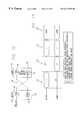
Images


Classifications
- H—ELECTRICITY
- H04—ELECTRIC COMMUNICATION TECHNIQUE
- H04B—TRANSMISSION
- H04B3/00—Line transmission systems
- H04B3/02—Details
- H04B3/32—Reducing cross-talk, e.g. by compensating
- H—ELECTRICITY
- H04—ELECTRIC COMMUNICATION TECHNIQUE
- H04B—TRANSMISSION
- H04B3/00—Line transmission systems
- H04B3/02—Details
- H04B3/20—Reducing echo effects or singing; Opening or closing transmitting path; Conditioning for transmission in one direction or the other
- H04B3/23—Reducing echo effects or singing; Opening or closing transmitting path; Conditioning for transmission in one direction or the other using a replica of transmitted signal in the time domain, e.g. echo cancellers
- H—ELECTRICITY
- H04—ELECTRIC COMMUNICATION TECHNIQUE
- H04L—TRANSMISSION OF DIGITAL INFORMATION, e.g. TELEGRAPHIC COMMUNICATION
- H04L5/00—Arrangements affording multiple use of the transmission path
- H04L5/14—Two-way operation using the same type of signal, i.e. duplex
Definitions
- This inventionrelates to methods of enabling the transmission and reception of signals through unshielded twisted pairs of wires within a communications system.
- the inventionparticularly relates to a startup protocol for initiating normal transmission between transceivers within a high throughput communications system.
- a “high throughput” as used within the context of this disclosuremay include, but is not limited to, one gigabit (GB) per second.
- FIG. 1A basic communications system is illustrated in FIG. 1 .
- the systemincludes a hub and a plurality of computers serviced by the hub in a local area network (LAN).
- LANlocal area network
- Each of the computersis usually displaced from the hub by a distance which may be as great as approximately one hundred meters (100 m.).
- the computersare also displaced from each other.
- the hubis connected to each of the computers by a communications line.
- Each communication lineincludes unshielded twisted pairs of wires or cables. Generally, the wires or cables are formed from copper.
- Four unshielded twisted pairs of wiresare provided in each communication line between each computer and the hub.
- the system shown in FIG. 1is operative with several categories of unshielded twisted pairs of cables designated as categories 3, 4 and 5 in the telecommunications industry. Category 3 cables are the poorest quality (and lowest cost) and category 5 cables are the best quality (and highest cost).
- the throughput of a systemis the rate at which the system processes data and is usually expressed in bits/second.
- Most communications systemshave throughputs of 10 megabits (Mb) Aecond or 100 Mb/second.
- Mbmegabits
- a rapidly evolving area of communications system technologyenables 1 Gb/second full-duplex communication over existing category-5 unshielded twisted pair cables. Such a system is commonly referred to as “Gigabit Ethernet.”
- FIG. 2A portion of a typical Gigabit Ethernet is shown in FIG. 2 .
- the Gigabit Ethernetprovides for transmission of digital signals between one of the computers and the hub and the reception of such signals at the other of the computer and the hub.
- a similar systemcan be provided for each of the computers
- the systemincludes a gigabit medium independent interface (GMII) block which receives data in byte-wide format at a specified rate, for example 125 MHz, and passes the data onto the physical coding sublayer (PCS) which performs scrambling, coding, and a variety of control functions.
- the PCSencodes bits from the GMII into 5-level pulse amplitude modulation (PAM) signals.
- the five signal levelsare ⁇ 2, ⁇ 1, 0, +1, and +2.
- Communication between the computer and hubis achieved using four unshielded twisted pairs of wires or cables, each operating at 250 Mb/second, and eight transceivers, one positioned at each end of a unshielded twisted pair.
- the necessity of full-duplex bidirectional operationdictates the use of hybrid circuits at the two ends of each unshielded twisted pair.
- the hybridcontrols access to the communication line, thereby allowing for full-duplex bidirectional operation between the transceivers at each end of the communications line.
- Impairment signalsinclude echo, near-end crosstalk (NEXT), and far-end crosstalk (FEXT) signals.
- NXTnear-end crosstalk
- FXTfar-end crosstalk
- NEXTis an impairment signal that results from capacitive coupling of the signals from the near-end transmitters to the input of the receivers.
- the NEXT impairment signals encountered by the receiver in transceiver Aare shown in FIG. 3 .
- the crosstalk signals from transmitters B, C, and Dappears as noise to receiver A, which is attempting to detect the direct signal from transmitter E.
- Each of the receivers in the systemencounter the same effect and accordingly the signals passing through the receivers experience signal distortion due to NEXT impairment signals. For clarity of FIG. 3, only the NEXT impairment experienced by receiver A is illustrated.
- an echo impairment signalis produced by each transmitter on the receiver contained within the same transceiver as the transmitter.
- the echo impairment signal encountered by the receiver in each transceiveris shown in FIG. 4 .
- the crosstalk signals from transmittersappear as noise to the receivers, which are attempting to detect the signal from the transmitter at the opposite end of the communications line.
- Each of the receivers in the systemencounter the same effect and accordingly the signals passing through the receivers experience signal distortion due to the echo impairment signal.
- Far-end crosstalkis an impairment that results from capacitive coupling of the signal from the far-end transmitters to the input of the receivers.
- the FEXT impairment signals encountered by the receiver in transceiver Aare shown in FIG. 5 .
- the crosstalk signals from transmitters F, G, and Happears as noise to receiver A, which is attempting to detect the direct signal from transmitter E.
- Each of the receivers in the systemencounter the same effect and accordingly the signals passing through the receivers experience signal distortion due to the FEXT impairment signal. For clarity of FIG. 5 only the FEXT impairment experienced by receiver A is illustrated.
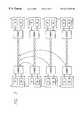
- FIG. 6Four transceivers at one end of a communications line are illustrated in detail in FIG. 6 .
- the components of the transceiversare shown as overlapping blocks, with each layer corresponding to one of the transceivers.
- the GMII, PCS, and hybrid of FIG. 6correspond to the GMII, PCS, and hybrid of FIG. 2 and are considered to be separate from the transceiver.
- the combination of the transceiver and hybridforms one “channel” of the communications system. Accordingly, FIG. 6 illustrates four channels, each of which operate in a similar manner.
- the transmitter portion of each transceiverincludes a pulse-shaping filter and a digital-to-analog (D/A) converter.
- D/Adigital-to-analog
- each transceiverincludes an analog-to-digital (A/D) converter, a first-in first-out (FIFO) buffer, a digital adaptive equalizer system including a feed-forward equalizer (FFE) and a detector.
- the receiver portionalso includes a timing recovery system and a near-end noise reduction system including a NEXT cancellation system and an echo canceller.
- phase adaptive filters contained within the transceiverconverge, the timing recovery subsystem acquires frequency and phase synchronization, the differences in delay among the four wire pairs are compensated, and pair identity and polarity is acquired. Successful completion of the startup allows normal operation of the transceiver to begin.
- blind startIn one startup protocol, known as “blind start”, the transceivers converge their adaptive filters and timing recovery systems simultaneously while also acquiring timing synchronization.
- a disadvantage of such a startupis that there is a high level of interaction among the various adaptation and acquisition algorithms within the transceiver. This high level of interaction reduces the reliability of the convergence and synchronization operations which occur during startup.
- the inventionrelates to methods of enabling the transmission and reception of signals through unshielded twisted pairs of wires within a communications system.
- the inventionparticularly relates to a startup protocol for initiating normal transmission between transceivers within a high throughput communications system.
- the inventionis a startup protocol for a communications system having a communications line with a master transceiver at a first end and a slave transceiver at a second end.
- Each transceiverhas a noise reduction system, a timing recovery system and at least one equalizer all converging at startup of the system.
- the startup protocolincludes the step of, for each transceiver, separating the convergence of the equalizer and the timing recovery system from the convergence of the noise reduction system.
- the step of separating the convergence of the equalizer and the timing recovery system from the convergence of the noise reduction systemincludes the step of converging the equalizer and the timing recovery system of the slave while converging the noise reduction system of the master. Also included is the step of, upon completion of converging the equalizer and the timing recovery system of the slave and the noise reduction system of the master, converging the equalizer and the timing recovery system of the master while converging the noise reduction system of the slave. Further included is the step of upon completion of converging the equalizer and the timing recovery system of the master and the noise reduction system of the slave, reconverging the noise reduction system of the master.
- the inventionis a startup protocol for use in a communications system having a plurality of transceivers, one transceiver acting as a master and another transceiver acting as slave, each transceiver having a noise reduction system, a timing recovery system and at least one equalizer.
- the startup protocolincludes the step of executing a first stage during which the timing recovery system and the equalizer of the slave are trained and the noise reduction system of the master is trained. Also included is the step of executing a second stage during which the timing recovery system and the equalizer of the master are trained and the noise reduction system of the slave is trained. Further included is the step of executing a third stage during which the noise reduction system of the master is retrained.
- the convergence of the equalizer and the timing recovery systemis separate from the convergence of the noise reduction system. Accordingly, the interaction among the various adaptation and acquisition algorithms within the transceiver is reduced and the reliability of the convergence and synchronization operations is improved.
- the startup protocolfurther includes the steps of transitioning from the first stage to the second stage and transitioning from the second stage to the third stage.
- each stageis of a fixed time duration and the transitioning between stages occurs upon completion of the time duration.
- the step of transitioning from the first stage to the second stageincludes the steps of transmitting a signal from the slave to the master; detecting the signal at the master; and ceasing transmission from the master.
- the step of transitioning from the second stage to the third stageincludes the steps of transmitting a signal from the master to the slave; detecting the signal at the slave; and continuing transmission from the slave.
- the inventionis a startup protocol for use in a communications system having a master transceiver at one end of a twisted wire pair and a slave transceiver at the opposite end of the twisted wire pair.
- Each transceiverhas a near-end noise reduction system, far-end noise reduction system, a timing recovery system and at least one equalizer.
- the protocolincludes the step of, during a first phase, maintaining the master in a half-duplex mode during which it transmits a signal but does not receive any signals, maintaining the slave in a half-duplex mode during which it receives the signal from the master but does not transmit any signals, converging the master near-end noise reduction system, adjusting the frequency and phase of the signal received by the slave such that the frequency and phase are synchronized with the frequency and phase of the signal transmitted by the master, and converging the equalizer of the slave.
- the inventionis a startup protocol for use in a communications system having a plurality of transceivers.
- a first one of the transceiversacts as a master and a second one of the transceivers acts as a slave, each transceiver includes a transmitter and a receiver.
- the protocolincludes the step of initially operating each of the first and second transceivers only as a transmitter and the other of the first and second transceivers only as a receiver to minimize a change in the operation of the transmitting transceiver transmitter as a result of the operation of the transmitting transceiver receiver and to provide adjustments in the timing of the receiving transceiver in accordance with the timing of the transmitting transceiver.
- the step of operating each of the first and second transceiverssimultaneously both as a transmitter and a receiver to minimize a change in the operation of the transmitter in the first transceiver as a result of the operation of the receiver in the first transceiver.
- the inventionis a startup protocol for use in a communications system having a plurality of transceivers.
- a first one of the transceiversacts as a master and a second one of the transceivers acts as a slave, each of the first and second one of the transceivers include a transmitter and a receiver.
- the protocolincludes the step of initially operating, in a first phase, the first transceiver only as a transmitter and the second transceiver only as a receiver and adjusting the timing of the second transceiver in accordance with the timing of the first transceiver and minimizing a change in the operation of the first transceiver as a transmitter as a result of the operation of the first transceiver as a receiver.
- FIG. 1is a schematic block diagram of a communications system providing a plurality of computers connected to a hub by communications lines to form a local area network (LAN);
- LANlocal area network
- FIG. 2is a schematic block diagram of a communications system providing a gigabit medium independent interface (GMII), a physical coding sublayer (PCS) and four transceiver channels each including an unshielded twisted wire pair and two transceivers, one at each end of the twisted wire pair;
- GMIIgigabit medium independent interface
- PCSphysical coding sublayer
- FIG. 3is a schematic block diagram of a portion of the communications system of FIG. 2 depicting the NEXT impairment signals received by receiver A from adjacent transmitters B, C, and D;
- FIG. 4is a schematic block diagram of a portion of the communications system of FIG. 2 depicting the echo impairment signal received by receiver A from transmitter A;
- FIG. 5is a schematic block diagram of a portion of the communications system of FIG. 2 depicting the FEXT impairment signals received by receiver A from opposite transmitters F, G, and H;
- FIG. 6is a schematic block diagram of a communications system including a plurality of transceivers, each having a NEXT cancellation system, an echo canceller, a feed forward equalizer, digital adaptive filter system including one detector, and a timing recovery circuit;
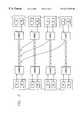
- FIG. 7is a schematic block diagram of a communications system in accordance with one embodiment of the present invention including a plurality of transceivers each having a NEXT cancellation system, an echo canceller, and a FEXT cancellation system, digital adaptive filter system including a plurality of detectors and a skew adjuster, and a timing recovery circuit;
- FIG. 8is a schematic block diagram of a symbol-by-symbol detector of FIGS. 7, each including a plurality of slicers, feedback filters and adders and receiving as input a soft decision;
- FIG. 9is a schematic block diagram of the NEXT cancellation systems of FIGS. 7, each including a plurality of adaptive transversal filters (ATF) and adders and receiving as input transmitted signals from adjacent transmitters;
- ATFadaptive transversal filters
- FIG. 10is a schematic block diagram of the echo cancellers of FIGS. 7, each including an ATF and receiving as input transmitted signals from same transmitters;
- FIG. 11is a schematic block diagram of the FEXT cancellation systems of FIGS. 7, each including a plurality of ATFs and an adder and receiving as input transmitted signals from opposite transmitters;
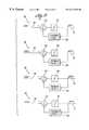
- FIG. 12is a schematic block diagram depicting the master-slave relationship between the transceivers of each of the transceiver channels of FIG. 2;
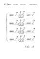
- FIG. 13is a timing diagram depicting the stages of a startup protocol in accordance with the invention.
- a communications system which may incorporate the features of this inventionis generally indicated at 10 in FIG. 1 .
- the system 10includes a hub 12 and a plurality of computers serviced by the hub in a local area network (LAN).
- LANlocal area network
- computers 14are shown by way of illustration but a different number of computers may be used without departing from the scope of the invention.
- Each of the computers 14may be displaced from the hub 12 by a distance as great as approximately one hundred meters (100 m.).
- the computers 14are also displaced from each other.
- the hub 12is connected to each of the computers 14 by a communications line 16 .
- the communication line 16comprises a plurality of unshielded twisted pairs of wires or cables. Generally, the wires or cables are formed from copper. Four unshielded twisted pairs of wires are provided in the system 10 between each computer and the hub 12 .
- the system shown in FIG. 1is operative with several categories of twisted pairs of cables designated as categories 3, 4 and 5 in the telecommunications industry. Category 3 cables are the poorest quality (and lowest cost) and category 5 cables are the best quality (and highest cost). Gigabit Ethernet uses category 5 cables.
- FIG. 2illustrates, in detail, a portion of the communications system of FIG. 1 including one communications line 16 and portions of one of the computers 14 and the hub 12 .
- the communications line 16includes four unshielded twisted pairs of wires 18 operating at 250 Mb/second per pair.
- a transceiver 20including a transmitter (TX) 22 and receiver (RX) 24 , is positioned at each unshielded end of each twisted pair 18 .
- TXtransmitter
- RXreceiver
- the hybrid 26controls access to the communication line 16 , thereby allowing for full-duplex bidirectional operation between the transceivers 20 at each end of the communications line.
- the hybridalso functions to isolate the transmitter and receiver associated with the transceiver, from each other.
- the communications systemincludes a standard connector designated as a GMII.
- the GMIImay be an eight bit wide data path in both the transmit and receive directions. Clocked at a suitable frequency, such as 125 MHz, the GMII results in a net throughput in both directions of data at a suitable rate such as 250 Mb/second per pair.
- the GMIIprovides a symmetrical interface in both the transmit and receive directions.
- a physical coding sublayer (PCS) 30receives and transmits data between the GMII 28 and the transceivers 20 .
- the PCS 30performs such functions as scrambling and encoding/decoding data before forwarding the data to either the transceiver or the GMII.
- the PCSencodes bits from the GMII into 5-level pulse amplitude modulation (PAM) signals.
- the five signal levelsare ⁇ 2, ⁇ 1, 0, +1, and +2.
- the PCSalso controls several functions of the transceivers, such as skew control as explained below.
- each transceiver 20includes a pulse shaping filter 32 and a D/A converter 34 .
- the pulse shaping filter 32receives one one-dimensional (1-D) symbol from the PCS.
- This symbolis referred to as a TXDatax symbol 36 , where x is 1 through 4 corresponding to each of the four channels.
- the TXDatax symbol 36represents 2 bits of data.
- the PCSgenerates one 1-D symbol for each of the channels.
- the symbol for each channelgoes through a spectrum shaping filter of the form 0.75+0.25 z ⁇ 1 at the pulse shaping filter 32 to limit emissions within FCC requirements.
- This simple filtershapes the spectrum at the output of the transmitter so that its power spectral density falls under that of communications systems operating at 100 Mb/second on two pairs of category ⁇ 5 twisted pair wires.
- the symbolis then converted into an analog signal by the D/A converter 34 which also acts as a lowpass filter.
- the analog signalgains access to the unshielded twisted pair wire 18 through the hybrid circuitry 26 .
- each transceiverincludes a signal detector 41 , an A/D converter 42 , a FIFO 44 , a digital adaptive equalizer system, a timing recovery circuit and a noise reduction system.
- the digital adaptive equalizer systemincludes a FFE 46 , two devices 50 , 56 , a skew adjuster 54 and two detectors 58 , 60 . The functions of these components are explained below.
- the general concept of the use of a digital adaptive equalizer in a communications systemis disclosed in U.S. Pat. No. 5,604,741 to Samueli et al. entitled ETHERNET SYSTEM.
- the noise reduction systemcomprises a near-end noise reduction system which includes a NEXT cancellation system 38 and an echo canceller 40 , and a far-end noise reduction system which includes a FEXT cancellation system 70 .
- a near-end noise reduction systemwhich includes a NEXT cancellation system 38 and an echo canceller 40
- a far-end noise reduction systemwhich includes a FEXT cancellation system 70 . Details of the noise reduction system are disclosed in copending patent application Ser. No. 09/037,238 entitled APPARATUS FOR, AND METHOD OF, REDUCING NOISE IN A COMMUNICATIONS SYSTEM and assigned of record to the assignee of record of this application.
- the A/D converter 42receives signals from the hybrid 26 and provides digital conversions of the signals received at a suitable frequency, such as 125 MHz, which is equal to the baud rate of the signals.
- the A/D converter 42samples the analog signals in accordance with an analog sample clock signal 78 provided by the decision-directed timing recovery circuit 64 .
- the FIFO 44receives the digital conversion signals from the A/D converter 42 and stores them on a first-in-first-out basis.
- the FIFOforwards individual signals to the FFE 46 in accordance with a digital sample clock signal 80 provided by the timing recovery circuit 64 .
- the FFE 46receives digital signals from the FIFO and filters these signals.
- the FFE 46is a least mean squares (LMS) type adaptive filter which performs channel equalization and precursor inter symbol interference (ISI) cancellation to correct for distortions in the signal.
- LMSleast mean squares
- the signal introduced into the A/D converter 42 and subsequently into the FIFO 44 and FFE 46has several components. These components include the direct signal received directly from the transmitter 22 at the opposite end of the unshielded twisted pair wire 18 with which the receiver 24 is associated. Also included are one or more of the NEXT, echo, and FEXT impairment signals from other transmitters 22 as previously described. The signal including the direct signal and one or more of the impairment signals is referred to as a “combination signal.”
- the FFE 46forwards the combination signal 48 to a second device 50 , typically a summing device.
- the combination signal 48is combined with the output 88 of the NEXT cancellation system 38 and output 90 of echo canceller 40 to produce a signal which is substantially devoid of NEXT and echo impairment signals.
- This signalis referred to as a “first soft decision” 52 .
- the signal detector 41detects the signals from the second device 50 and forwards the signals to the skew adjuster 54 . Upon signal detection, the signal detector 41 initiates various system operations, one of which—as described below—includes transitioning between phases of the startup protocol.
- the skew adjuster 54receives the first soft decision 52 from the second device 50 and outputs a signal referred to as a “second soft decision” 66 .
- the skew adjuster 54performs two functions. First, it compensates for the difference in length of the unshielded twisted pairs 18 by delaying the first soft decision 52 so that the second soft decisions 66 from all of the receivers in the system are in sync. Second, it adjusts the delay of the first soft decision 52 so that the second soft decision 66 arrives at the first device 56 at substantially the same time as the output of the FEXT cancellation system 70 .
- the skew adjuster 54receives skew control signals 82 from the PCS 30 .
- the skew adjuster 54forwards the second soft decision 66 to a first device 56 , typically a summing device. At the first device 56 the second soft decision 66 is combined with the output 94 of the FEXT cancellation system 70 to produce a signal which is substantially devoid of FEXT impairment signals. This signal is referred to as a “third soft decision” 68 .
- the first detector 58receives the third soft decision 68 from the first device 56 .
- the first detector 58provides an output signal, i.e., a “final decision” 72 .
- the detectormay be a slicer which produces a final decision 72 corresponding to the analog signal level closest in magnitude to the level of the third soft decision 68 .
- the detectormay also be either a symbol-by-symbol detector or a sequential detector which operates on sequences of signals across all four channels simultaneously, such as a Viterbi decoder.
- the first detector 58is a symbol-by-symbol detector.
- Each first detector 58includes a slicer 98 , adaptive feedback filter 100 and an adder 102 .
- the adder 102combines the third soft decision 68 with the output of the adaptive feedback filter 100 to provide an output which is introduced to the slicer 98 .
- the output of the slicer 98in introduced to the adaptive feedback filter 100 .
- the first detector 58provides an output signal 72 which corresponds to the discrete level from the set [ ⁇ 2, ⁇ 1, 0, 1, 2] which is closest to the difference between the third soft decision 68 and the output of the feedback filter 100 .
- the adaptive feedback filter 100corrects for distortion in the third soft decision 68 .
- This filter 100uses past slicer 98 decisions to estimate postcursor ISI caused by the channel. This ISI is canceled from the third soft decision 68 to form the final decision
- the first detector 58is a combination of a sequential decoder with a decision feedback equalizer (DFE) using the architecture usually known as multiple DFE architecture (MDFE) sequential detector.
- the sequential decoder 58looks at all signals from all four channels at the same time and at successive samples from each channel over several periods of unit time.
- a sequential decoderreceives as input at least one signal from each of the first devices 56 .
- the sequential decoder 58in general, is responsive to the sequences of the output signals from the first devices 56 for (1) passing acceptable sequences of such signals and (2) discarding unacceptable sequences of such signals in accordance with the constraints established by the code standard associated with the system. Acceptable sequences are those which obey the code constraints and unacceptable sequences are those which violate the code constraints.
- the second detector 60receives the first soft decision 52 from the second device 50 .
- the second detector 60is a symbol-by-symbol detector. It provides an output signal 74 which corresponds to the discrete level from the set [ ⁇ 2, ⁇ 1, 0, 1, 2] which is closest to the difference between the first soft decision 52 and the output of the feedback filter 100 .
- the second detector 60produces output signals 74 without the benefit of FEXT cancellation, as a result, these decisions have a higher error rate than those made by the first detector 58 , which enjoys the benefits of FEXT cancellation. Because of this fact, these decisions are called “tentative decisions”.
- the coefficients of this adaptive feedback filter 100are the same as those of the adaptive feedback filter associated with the first detector 58 (FIG. 7 ).
- a third device 62receives the first soft decision signal 52 from the second device 50 and the tentative decision signals 74 from the second detector 60 .
- the first soft decision 52is combined with the tentative decision signal 74 to produce an error signal 76 which is introduced into the timing recovery circuit 64 .
- the timing recovery circuit 64receives the tentative decision 74 from the second detector 60 and the error signals 76 from the third device 62 . Using these signals as inputs the timing recovery circuit 64 outputs an analog clock sync signal 78 which is introduced to the A/D converter 42 and a digital clock sync signal 80 which is introduced into the FIFO 44 .
- these signalscontrol the rate at which the A/D converter 42 samples the analog input it receives from the hybrid 26 and the rate at which the FIFO forwards digital signals to the FFE 46 .
- a suitable timing recovery device for use in the present inventionis disclosed in copending patent application Ser. No. 08/970,557 entitled APPARATUS FOR, AND METHOD OF, PROCESSING SIGNALS TRANSMITTED OVER A LOCAL AREA NETWORK and assigned of record to the assignee of record of this application.
- each NEXT cancellation system 38receives three TXDatax symbols 36 from each of the transmitters at the same end of the communications line 18 as the receiver with which the NEXT cancellation system is associated.
- Each NEXT cancellation system 38includes three filters 84 , one for each of the TXDatax symbols 36 .
- filters 84model the impulse responses of the NEXT noise from the transmitters and may be implemented as adaptive transversal filters (ATF) employing, for example, the LMS algorithm.
- the filters 84produce a replica of the NEXT impairment signal for each TXDatax symbol 36 .
- a summing device 86combines the three individual replica NEXT impairment signals 92 to produce a replica of the NEXT impairment signal contained within the combination signal received by the receiver with which the NEXT cancellation system 38 is associated.
- the replica NEXT impairment signal 88is introduced into the second device 50 (FIG. 7) where it is combined with the combination signal 48 to produce a first soft decision signal 52 which is substantially devoid of NEXT impairment signals.
- Echo cancellationis accomplished with an adaptive cancelling filter 85 as shown in the block diagram of FIG. 10 .
- Each echo canceller 40receives the TXDatax symbols 36 from the transmitter at the same end of the twisted wire pair 18 as that of the receiver with which the echo canceller is associated.
- each echo canceller 40includes one filter 85 .
- These filters 85model the impulse responses of the echo noise from the transmitter and may be implemented as ATFs employing, for example, the LMS algorithm.
- the filterproduces a replica of the echo impairment signal contained within the combination signal received by the receiver with which the echo canceller 40 is associated.
- the replica echo impairment signal 90is introduced into the second device 50 (FIG. 6) where it is combined with the combination signal 48 to produce the first soft decision signal 52 which is substantially devoid of echo impairment signals.
- Each FEXT cancellation system 70receives three tentative decision symbols 74 one from each of the receivers at the same end of the communications line as the receiver with which the FEXT cancellation system is associated.
- Each FEXT cancellation system 70includes three filters 87 , one for each of the tentative decision symbols 74 .
- These filters 87model the impulse responses of the FEXT noise from transmitters and may be implemented as ATFs employing, for example, the LMS algorithm.
- the filters 87produce a replica of the FEXT impairment signal 96 for each individual tentative decision symbol 74 .
- a summing device 108combines the three individual replica FEXT impairment signals 96 to produce a replica of the FEXT impairment signal contained within the combination signal 48 received by the receiver with which the FEXT cancellation system is associated.
- the replica FEXT impairment signal 94is introduced into the first device 56 (FIG. 7) where it is combined with the second combination signal 66 to produce the third soft decision signal 68 which is substantially devoid of FEXT impairment signals. It is important to note that the higher error rate of the tentative decisions 74 does not degrade the performance of the FEXT cancellation system 70 , because the decisions used to cancel FEXT are statistically independent from the final decisions 72 made by the receiver whose FEXT is being canceled.
- the symbols provided by the first detector 58are decoded and descrambled by the receive section of the PCS 30 before being introduced to the GMII. Variations in the way the wire pairs are twisted may cause delays through the four channels by up to 50 nanoseconds. As a result, the symbols across the four channels may be out of sync. As previously mentioned, in the case where the first detector is a sequential detector, the PCS also determines the relative skew of the four streams of 1-D symbols and adjusts the symbol delay, through the skew adjuster 54 , prior to their arrival at the first detector 58 so that sequential decoder can operate on properly composed four-dimensional (4-D) symbols. Additionally, since the cabling plant may introduce wire swaps within a pair and pair swaps among the four unshielded twisted pairs, the PCS 30 also determines and corrects for these conditions.
- the transceiver startupOne of the most critical phases of the operation of the communications system is the transceiver startup.
- the adaptive filters contained within the FFE 46 (FIG. 7 ), echo canceller 40 , NEXT cancellation system 38 , FEXT cancellation system 70 , timing recovery system 64 and detector 58 of the receiver portion of each transceiverconverge.
- the actual output of the adaptive filtersare compared to expected output of the filters to determine the error.
- the erroris reduced to substantially zero by adjusting the coefficients of the algorithm which defines the transfer function of the filter.
- the timing recovery systemis converged by adjusting the frequency and phase of the phase lock loop and the local oscillator contained within the timing recovery system so that the signal-to-noise ratio of the channel is optimized.
- the differences in delay among the four wire pairsare compensated, and pair identity and polarity, are acquired. Successful completion of the startup ensures that the transceiver can begin normal operation.
- each of the transceiver channelsoperate in a loop-timed fashion, as shown in FIG. 12 .
- the transceivers 20 at the two ends of the each twisted wire pair 18assume two different roles as far as synchronization is concerned.
- One of the transceiverscalled the master 110 , transmits data using an independent clock GTX_CLK provided through the GMII interface 28 (FIG. 7 ).
- This clock signalis fixed in both frequency and phase and is provided to the master transceiver 110 of each the four transceiver channels in the communications system.
- the transmit clock used by the master 110may be a filtered version of GTX_CLK, obtained using a phase locked loop with a very narrow bandwidth, to reduce jitter.
- the transceiver 20 at the other end of the twisted wire pair 18synchronizes both the frequency and phase of its receive and transmit clocks to the signal received from the master 110 , using the timing recovery system 64 (FIG. 7) located in the receiver 24 .
- the slave 112 transmit clockmaintains a fixed phase relationship with the slave receive clock at all times.
- the receive clock at the master 110synchronizes, in phase but not in frequency, with the signal received from the slave transmitter 22 .
- the master 110 receive clockfollows the master transmit clock with a phase difference determined by the round trip delay of the loop. This phase relationship may vary dynamically as a result of the need of the master 110 receive clock to track jitter present in the signal received from the slave 112 .
- the sequence of events during the startup protocol of the present inventionis shown in FIG. 13 .
- the protocolconsists of three phases 114 , 116 , 118 during which the receivers are trained, e.g., adaptive filters are converged, timing synchronization is acquired, etc., followed by normal operation which begins during phase four 120 .
- the masterbegins transmitting to the slave using a transmit clock signal that is fixed in both frequency and phase.
- the mastertrains its near-end noise reduction system by converging the adaptive filters contained within its echo canceller and NEXT cancellation system (E).
- the slavetrains its equalizers and far-end noise reduction system by converging the adaptive filters contained within its DFE, FFE and FEXT cancellation system (D).
- DFEDFE, FFE and FEXT cancellation system
- the slaveWhile training its equalizer and far-end noise reduction system the slave simultaneously acquires timing synchronization in both frequency and phase (T). It may also at this time compensate for the differential delay among the four twisted wire pairs, identify the four
- the transition from the first phase 114 to the second phase 116occurs after a fixed and prespecified period of time.
- the slavetransitions from the first phase 114 to second phase 116 when it detects that its receiver has converged the adaptive filters contained within its DFE, FFE and FEXT cancellation system (D) and has acquired timing synchronization (T).
- the master receiverincludes a signal detector 41 (FIG. 7) which detects energy in the line coming from the slave.
- the mastertransitions from the first phase 114 to the second phase 116 when it detects this energy from the slave. Therefore, the slave takes the initiative in transitioning from the first phase 114 to the second phase 116 , and the master follows when it detects the signal from the slave.
- the convergence of the echo canceller and NEXT cancellation system during the first phase 114 at the masteris done with the objective of allowing the signal detector at the master to detect the signal from the slave. Without proper echo and NEXT cancellation, the signal detector would be triggered by the echo and NEXT noise present in the receiver.
- the masterdiscards the echo canceller and NEXT cancellation system coefficients which result from the converging in the first phase 114 . This may be done by resetting the adaptive filters in the echo canceller and NEXT cancellation system.
- the echo canceller and NEXT cancellation system coefficients obtained during the first phase 114may differ from the final values to be reacquired in the third phase 118 .
- the slavetrains its near-end noise reduction system by converging the adaptive filters contained within its echo canceller and NEXT cancellation system (E).
- the mastertrains its equalizers and far-end noise reduction system by converging the adaptive filters contained within its DFE, FFE and FEXT cancellation system (D).
- the mastersimultaneously acquires timing synchronization in phase only (P). The master may also at this time compensate for the differential delay among the four twisted wire pairs, identify the four pairs, and correct the polarity of the pairs.
- the slavesaves the timing recovery state variables that had been acquired during the first phase 114 , and freezes its frequency and phase.
- the slaveis guaranteed to sample with the correct phase, the signal coming to it from the master when the master resumes transmission at the beginning of the third phase 118 .
- the slavealso freezes the coefficients of the DFE, FFE and FEXT cancellation system acquired during the first phase 114 .
- a startup protocol for use in a system having a slave which transmits using a free-running clockis disclosed in copending patent application Ser. No. 09/078,466 entitled STARTUP PROTOCOL FOR HIGH THROUGHPUT COMMUNICATIONS SYSTEMS and assigned of record to the assignee of record of this application.
- the transition from the second phase 116 to the third phase 118may occur after a fixed and prespecified period of time. While the duration of the first, second, and third phases 114 , 116 , 118 is fixed, the duration is not necessarily equal for all phases. In a preferred embodiment, however, the master transitions from the second phase 116 to third phase 118 when it detects that its receiver has converged the adaptive filters contained within its DFE, FFE and FEXT cancellation system (D) and has acquired timing synchronization (P). Like the master, the slave receiver includes a signal detector 41 (FIG. 7) which detects energy in the line coming from the master. The slave transitions from the second phase 116 to the third phase 118 when it detects this energy from the master. Therefore the master takes the initiative in transitioning from the second phase 116 to the third phase 118 , and the slave follows when it detects the signal from the master.
- FFE and FEXT cancellation systemD
- Ptiming synchronization
- the slave receiverincludes a signal detector 41 (FI
- the slavefreezes the coefficients of the echo cancellers and NEXT cancellation system and maintains a steady state condition during which the operating characteristics of the slave are not adjusted.
- the masterfreezes the coefficients of the DFE, FFE and FEXT cancellation system and the phase of its clock signal.
- the masteralso retrains its near-end noise reduction system by reconverging its echo canceller and NEXT cancellation system (E) during the third phase 118 . It is important to note that in the third phase 118 the slave resumes transmission using the clock recovered from the signal transmitted by the master, and therefore the master already knows the correct frequency with which to operate its receiver.
- the “relative sampling phases” of the four receiversi.e., the differences in sampling phases of three of the receivers versus one of them arbitrarily used as reference, are also known, because they were acquired during the second phase 116 .
- the “overall sampling phase” of the receiversi.e., the sampling phase of the receiver arbitrarily chosen as reference, is not yet known and has to be acquired during the third phase 118 .
- both master and slavehave completed their training operations, they exchange messages indicating that they are ready to transmit valid data.
- phase four 120all coefficients of the adaptive filters previously frozen are unfrozen and the transmission of data is ready to take place.
Landscapes
- Engineering & Computer Science (AREA)
- Signal Processing (AREA)
- Computer Networks & Wireless Communication (AREA)
- Cable Transmission Systems, Equalization Of Radio And Reduction Of Echo (AREA)
Abstract
Description
Claims (18)
Priority Applications (9)
| Application Number | Priority Date | Filing Date | Title |
|---|---|---|---|
| US09/078,993US6212225B1 (en) | 1998-05-14 | 1998-05-14 | Startup protocol for high throughput communications systems |
| AU29934/99AAU748582C (en) | 1998-03-09 | 1999-03-08 | Gigabit ethernet transceiver |
| CA002320701ACA2320701C (en) | 1998-03-09 | 1999-03-08 | Gigabit ethernet transceiver |
| US09/781,853US6792038B2 (en) | 1998-05-14 | 2001-02-12 | Startup protocol for high throughput communications systems |
| US10/282,447US8189650B2 (en) | 1998-05-14 | 2002-10-29 | Startup protocol for high throughput communications systems |
| US10/767,514US7492813B2 (en) | 1998-05-14 | 2004-01-29 | Startup protocol for high throughput communications systems |
| JP2005011419AJP4216812B2 (en) | 1998-03-09 | 2005-01-19 | Gigabit Ethernet transceiver |
| JP2005011426AJP4216813B2 (en) | 1998-03-09 | 2005-01-19 | Gigabit Ethernet transceiver |
| US12/372,575US20090154536A1 (en) | 1998-05-14 | 2009-02-17 | Startup protocol for high throughput communications systems |
Applications Claiming Priority (1)
| Application Number | Priority Date | Filing Date | Title |
|---|---|---|---|
| US09/078,993US6212225B1 (en) | 1998-05-14 | 1998-05-14 | Startup protocol for high throughput communications systems |
Related Child Applications (1)
| Application Number | Title | Priority Date | Filing Date |
|---|---|---|---|
| US09/781,853ContinuationUS6792038B2 (en) | 1998-05-14 | 2001-02-12 | Startup protocol for high throughput communications systems |
Publications (1)
| Publication Number | Publication Date |
|---|---|
| US6212225B1true US6212225B1 (en) | 2001-04-03 |
Family
ID=22147447
Family Applications (5)
| Application Number | Title | Priority Date | Filing Date |
|---|---|---|---|
| US09/078,993Expired - LifetimeUS6212225B1 (en) | 1998-03-09 | 1998-05-14 | Startup protocol for high throughput communications systems |
| US09/781,853Expired - LifetimeUS6792038B2 (en) | 1998-05-14 | 2001-02-12 | Startup protocol for high throughput communications systems |
| US10/282,447Expired - Fee RelatedUS8189650B2 (en) | 1998-05-14 | 2002-10-29 | Startup protocol for high throughput communications systems |
| US10/767,514Expired - Fee RelatedUS7492813B2 (en) | 1998-05-14 | 2004-01-29 | Startup protocol for high throughput communications systems |
| US12/372,575AbandonedUS20090154536A1 (en) | 1998-05-14 | 2009-02-17 | Startup protocol for high throughput communications systems |
Family Applications After (4)
| Application Number | Title | Priority Date | Filing Date |
|---|---|---|---|
| US09/781,853Expired - LifetimeUS6792038B2 (en) | 1998-05-14 | 2001-02-12 | Startup protocol for high throughput communications systems |
| US10/282,447Expired - Fee RelatedUS8189650B2 (en) | 1998-05-14 | 2002-10-29 | Startup protocol for high throughput communications systems |
| US10/767,514Expired - Fee RelatedUS7492813B2 (en) | 1998-05-14 | 2004-01-29 | Startup protocol for high throughput communications systems |
| US12/372,575AbandonedUS20090154536A1 (en) | 1998-05-14 | 2009-02-17 | Startup protocol for high throughput communications systems |
Country Status (1)
| Country | Link |
|---|---|
| US (5) | US6212225B1 (en) |
Cited By (17)
| Publication number | Priority date | Publication date | Assignee | Title |
|---|---|---|---|---|
| US20040170230A1 (en)* | 2002-11-07 | 2004-09-02 | Zimmerman George A. | Method and apparatus for equalization and crosstalk mitigation |
| US6792038B2 (en)* | 1998-05-14 | 2004-09-14 | Broadcom Corporatin | Startup protocol for high throughput communications systems |
| US20050074055A1 (en)* | 2003-10-06 | 2005-04-07 | Hiroshi Takatori | System, method and apparatus for crosstalk cancellation |
| US20050157779A1 (en)* | 1998-06-19 | 2005-07-21 | Kazutomo Hasegawa | Digital subscriber line communicating system and a transceiver in the system |
| US6965657B1 (en)* | 1999-12-01 | 2005-11-15 | Velocity Communication, Inc. | Method and apparatus for interference cancellation in shared communication mediums |
| US20070162943A1 (en)* | 1995-02-06 | 2007-07-12 | Adc Telecommunications, Inc. | Multipoint-to-point communication using orthogonal frequency division multiplexing |
| EP1956725A1 (en) | 2007-02-07 | 2008-08-13 | ECI Telecom Ltd. | Method for estimating crosstalk interferences in a communication network |
| US20080239939A1 (en)* | 2003-04-28 | 2008-10-02 | Parnaby Gavin D | Frequency domain echo and next cancellation |
| US20080275929A1 (en)* | 2007-02-07 | 2008-11-06 | Mark Joseph Callicotte | Use of line characterization to configure physical layered devices |
| US20090080325A1 (en)* | 2007-09-26 | 2009-03-26 | Parnaby Gavin D | Crosstalk cancellation using sliding filters |
| US20090116639A1 (en)* | 2002-11-07 | 2009-05-07 | Zimmerman George A | Method and apparatus for crosstalk mitigation |
| US20090257578A1 (en)* | 2008-04-15 | 2009-10-15 | Chih-Yung Shih | Network Apparatus Capable of Canceling Far-End-Crosstalk and Network Signal Processing Method thereof |
| USRE41771E1 (en) | 1995-02-06 | 2010-09-28 | Adc Telecommunications, Inc. | System for multiple use subchannels |
| USRE42236E1 (en) | 1995-02-06 | 2011-03-22 | Adc Telecommunications, Inc. | Multiuse subcarriers in multipoint-to-point communication using orthogonal frequency division multiplexing |
| US8761387B2 (en) | 2006-05-04 | 2014-06-24 | Mindspeed Technologies, Inc. | Analog transmit crosstalk canceller |
| US9253072B2 (en)* | 2012-10-24 | 2016-02-02 | Broadcom Corporation | Polarity detection system |
| US9306774B2 (en) | 2013-11-11 | 2016-04-05 | Denso Corporation | Communication apparatus |
Families Citing this family (17)
| Publication number | Priority date | Publication date | Assignee | Title |
|---|---|---|---|---|
| US6201796B1 (en)* | 1998-05-14 | 2001-03-13 | Broadcom Corporation | Startup protocol for high throughput communications systems |
| US6901119B2 (en)* | 2001-02-22 | 2005-05-31 | International Business Machines Corporation | Method and apparatus for implementing soft-input/soft-output iterative detectors/decoders |
| US7796544B2 (en)* | 2002-06-07 | 2010-09-14 | Tokyo Electron Limited | Method and system for providing an analog front end for multiline transmission in communication systems |
| TWI231673B (en)* | 2002-11-07 | 2005-04-21 | Realtek Semiconductor Corp | A modulator used for network transceiver and method thereof |
| US7082157B2 (en)* | 2002-12-24 | 2006-07-25 | Realtek Semiconductor Corp. | Residual echo reduction for a full duplex transceiver |
| US7200196B2 (en)* | 2003-04-24 | 2007-04-03 | Texas Instruments Incorporated | Interpolation based timing recovery |
| US7593315B2 (en)* | 2004-02-09 | 2009-09-22 | Cisco Technology, Inc. | Cable diagnostics for 10GBASE-T transceivers |
| US7729464B2 (en)* | 2006-12-22 | 2010-06-01 | Teranetics, Inc. | Aiding synchronization between master and slave transceivers |
| WO2008085299A1 (en) | 2007-01-09 | 2008-07-17 | Rambus Inc. | Receiver with clock recovery circuit and adaptive sample and equalizer timing |
| US8284882B2 (en)* | 2009-06-25 | 2012-10-09 | Lsi Corporation | Methods and apparatus for qualification of update of clock recovery and equalization |
| US8665929B1 (en)* | 2011-05-12 | 2014-03-04 | Valens Semiconductor Ltd. | Method and device for deterministic timing acquiring and tracking |
| CN103814338A (en) | 2011-07-20 | 2014-05-21 | 航空网络公司 | Systems and methods of network synchronization |
| US9094339B2 (en) | 2012-04-30 | 2015-07-28 | Cisco Technology, Inc. | Computer system communication channel diagnostics |
| TWI528740B (en)* | 2013-10-29 | 2016-04-01 | 瑞昱半導體股份有限公司 | Network apparatus with multiple transport ports |
| US11831739B2 (en)* | 2020-06-22 | 2023-11-28 | Sony Semiconductor Solutions Corporation | Communication apparatus and communication system |
| EP4385135A1 (en)* | 2021-08-12 | 2024-06-19 | Marvell Asia Pte Ltd | Link training for a full-duplex ethernet link |
| US12413261B2 (en)* | 2021-09-01 | 2025-09-09 | Intel Corporation | Near-end crosstalk cancellation system |
Citations (15)
| Publication number | Priority date | Publication date | Assignee | Title |
|---|---|---|---|---|
| US5181198A (en) | 1991-03-12 | 1993-01-19 | Bell Communications Research, Inc. | Coordinated transmission for two-pair digital subscriber lines |
| US5307405A (en) | 1992-09-25 | 1994-04-26 | Qualcomm Incorporated | Network echo canceller |
| US5388092A (en) | 1989-06-27 | 1995-02-07 | Nec Corporation | Echo canceller for two-wire full duplex digital data transmission |
| US5517435A (en) | 1993-03-11 | 1996-05-14 | Nec Corporation | Method of identifying an unknown system with a band-splitting adaptive filter and a device thereof |
| US5526347A (en) | 1992-11-02 | 1996-06-11 | Advanced Micro Devices, Inc. | Decorrelation controller for an adaptive echo cancellor |
| US5539773A (en) | 1992-02-17 | 1996-07-23 | Thomson Consumer Electronics S.A. | Method and apparatus for ghost cancelling and/or equalizing |
| US5604741A (en) | 1995-03-16 | 1997-02-18 | Broadcom Corporation | Ethernet system |
| US5659609A (en) | 1994-09-05 | 1997-08-19 | Fujitsu Limited | Echo canceller and waveform-distortion compensation device |
| US5668802A (en)* | 1993-11-11 | 1997-09-16 | Gpt Limited | High-speed digital subscriber lines |
| US5694437A (en)* | 1995-10-10 | 1997-12-02 | Motorola, Inc. | Device and method for data signal detection in the presence of distortion and interference in communication systems |
| US5796725A (en) | 1994-08-31 | 1998-08-18 | Nec Corporation | Echo canceller capable of cancelling an echo signal at a high speed |
| US5812537A (en)* | 1995-09-29 | 1998-09-22 | Paradyne Corporation | Echo canceling method and apparatus for data over cellular |
| US5828657A (en)* | 1995-09-29 | 1998-10-27 | Paradyne Corporation | Half-duplex echo canceler training using a pilot signal |
| US5864545A (en)* | 1996-12-06 | 1999-01-26 | Altocom, Inc. | System and method for improving convergence during modem training and reducing computational load during steady-state modem operations |
| US6014374A (en) | 1985-03-20 | 2000-01-11 | Interdigital Technology Corporation | Subscriber RF telephone system for providing multiple speech and/or data signals simultaneously over either a single or a plurality of RF channels |
Family Cites Families (7)
| Publication number | Priority date | Publication date | Assignee | Title |
|---|---|---|---|---|
| US5163044A (en)* | 1991-01-02 | 1992-11-10 | At&T Bell Laboratories | Use of a fractionally spaced equalizer to perform echo cancellation in a full-duplex modem |
| US6317455B1 (en)* | 1997-12-16 | 2001-11-13 | 3Com Corporation | System and method for user information transfer before modem connection |
| US6201796B1 (en)* | 1998-05-14 | 2001-03-13 | Broadcom Corporation | Startup protocol for high throughput communications systems |
| US6212225B1 (en)* | 1998-05-14 | 2001-04-03 | Bradcom Corporation | Startup protocol for high throughput communications systems |
| US6240128B1 (en)* | 1998-06-11 | 2001-05-29 | Agere Systems Guardian Corp. | Enhanced echo canceler |
| JP3622510B2 (en) | 1998-06-19 | 2005-02-23 | 富士通株式会社 | Digital subscriber line transmission method, ADSL transceiver, channel analysis system method, and ADSL apparatus |
| US6965657B1 (en) | 1999-12-01 | 2005-11-15 | Velocity Communication, Inc. | Method and apparatus for interference cancellation in shared communication mediums |
- 1998
- 1998-05-14USUS09/078,993patent/US6212225B1/ennot_activeExpired - Lifetime
- 2001
- 2001-02-12USUS09/781,853patent/US6792038B2/ennot_activeExpired - Lifetime
- 2002
- 2002-10-29USUS10/282,447patent/US8189650B2/ennot_activeExpired - Fee Related
- 2004
- 2004-01-29USUS10/767,514patent/US7492813B2/ennot_activeExpired - Fee Related
- 2009
- 2009-02-17USUS12/372,575patent/US20090154536A1/ennot_activeAbandoned
Patent Citations (15)
| Publication number | Priority date | Publication date | Assignee | Title |
|---|---|---|---|---|
| US6014374A (en) | 1985-03-20 | 2000-01-11 | Interdigital Technology Corporation | Subscriber RF telephone system for providing multiple speech and/or data signals simultaneously over either a single or a plurality of RF channels |
| US5388092A (en) | 1989-06-27 | 1995-02-07 | Nec Corporation | Echo canceller for two-wire full duplex digital data transmission |
| US5181198A (en) | 1991-03-12 | 1993-01-19 | Bell Communications Research, Inc. | Coordinated transmission for two-pair digital subscriber lines |
| US5539773A (en) | 1992-02-17 | 1996-07-23 | Thomson Consumer Electronics S.A. | Method and apparatus for ghost cancelling and/or equalizing |
| US5307405A (en) | 1992-09-25 | 1994-04-26 | Qualcomm Incorporated | Network echo canceller |
| US5526347A (en) | 1992-11-02 | 1996-06-11 | Advanced Micro Devices, Inc. | Decorrelation controller for an adaptive echo cancellor |
| US5517435A (en) | 1993-03-11 | 1996-05-14 | Nec Corporation | Method of identifying an unknown system with a band-splitting adaptive filter and a device thereof |
| US5668802A (en)* | 1993-11-11 | 1997-09-16 | Gpt Limited | High-speed digital subscriber lines |
| US5796725A (en) | 1994-08-31 | 1998-08-18 | Nec Corporation | Echo canceller capable of cancelling an echo signal at a high speed |
| US5659609A (en) | 1994-09-05 | 1997-08-19 | Fujitsu Limited | Echo canceller and waveform-distortion compensation device |
| US5604741A (en) | 1995-03-16 | 1997-02-18 | Broadcom Corporation | Ethernet system |
| US5812537A (en)* | 1995-09-29 | 1998-09-22 | Paradyne Corporation | Echo canceling method and apparatus for data over cellular |
| US5828657A (en)* | 1995-09-29 | 1998-10-27 | Paradyne Corporation | Half-duplex echo canceler training using a pilot signal |
| US5694437A (en)* | 1995-10-10 | 1997-12-02 | Motorola, Inc. | Device and method for data signal detection in the presence of distortion and interference in communication systems |
| US5864545A (en)* | 1996-12-06 | 1999-01-26 | Altocom, Inc. | System and method for improving convergence during modem training and reducing computational load during steady-state modem operations |
Non-Patent Citations (1)
| Title |
|---|
| ITU-T V.34 A Modem Operating at Data Signalling Rates of up to 28 800 bit/s for Use on the General Switched Telephone Network and on Leased Point-To-Point2-Wire Telephone-Type Circuits.* |
Cited By (59)
| Publication number | Priority date | Publication date | Assignee | Title |
|---|---|---|---|---|
| US8547824B2 (en) | 1994-09-26 | 2013-10-01 | Htc Corporation | Systems and methods for orthogonal frequency divisional multiplexing |
| USRE44460E1 (en) | 1994-09-26 | 2013-08-27 | Htc Corporation | Systems for synchronous multipoint-to-point orthogonal frequency division multiplexing communication |
| US8638655B2 (en) | 1994-09-26 | 2014-01-28 | Htc Corporation | Systems and method for orthogonal frequency divisional multiplexing |
| US8199632B2 (en) | 1995-02-06 | 2012-06-12 | Htc Corporation | Systems and method for orthogonal frequency divisional multiplexing |
| US7672219B2 (en) | 1995-02-06 | 2010-03-02 | Adc Telecommunications, Inc. | Multipoint-to-point communication using orthogonal frequency division multiplexing |
| US7983141B2 (en) | 1995-02-06 | 2011-07-19 | Geile Michael J | Synchronized multipoint-to-point communication using orthogonal frequency division |
| US7957265B2 (en) | 1995-02-06 | 2011-06-07 | Adc Telecommunications, Inc. | Systems and method for orthogonal frequency divisional multiplexing |
| US20070162943A1 (en)* | 1995-02-06 | 2007-07-12 | Adc Telecommunications, Inc. | Multipoint-to-point communication using orthogonal frequency division multiplexing |
| US20080049604A1 (en)* | 1995-02-06 | 2008-02-28 | Adc Telecommunications, Inc. | Systems and method for orthogonal frequency divisional multiplexing |
| US20080056398A1 (en)* | 1995-02-06 | 2008-03-06 | Adc Telecommunications, Inc. | Systems and method for orthogonal frequency divisional multiplexing |
| US8576693B2 (en) | 1995-02-06 | 2013-11-05 | Htc Corporation | Systems and method for orthogonal frequency division multiplexing |
| US8089853B2 (en) | 1995-02-06 | 2012-01-03 | Htc Corporation | Systems and method for orthogonal frequency divisional multiplexing |
| US8406115B2 (en) | 1995-02-06 | 2013-03-26 | Htc Corporation | Systems and methods for orthogonal frequency division multiplexing |
| US8351321B2 (en) | 1995-02-06 | 2013-01-08 | Htc Corporation | Systems and method for orthogonal frequency divisional multiplexing |
| US8315150B2 (en) | 1995-02-06 | 2012-11-20 | Htc Corporation | Synchronized multipoint-to-point communication using orthogonal frequency division |
| US7936662B2 (en) | 1995-02-06 | 2011-05-03 | Adc Telecommunications, Inc. | Ranging and round trip delay timing adjustment in a multi-point to point bidirectional communication system |
| US8213398B2 (en) | 1995-02-06 | 2012-07-03 | Htc Corporation | Method for multiple use subchannels |
| US8213399B2 (en) | 1995-02-06 | 2012-07-03 | Htc Corporation | System for multiple use subchannels |
| US7995454B2 (en) | 1995-02-06 | 2011-08-09 | Htc Corporation | Systems and method for orthogonal frequency divisional multiplexing |
| USRE42236E1 (en) | 1995-02-06 | 2011-03-22 | Adc Telecommunications, Inc. | Multiuse subcarriers in multipoint-to-point communication using orthogonal frequency division multiplexing |
| US7675843B2 (en) | 1995-02-06 | 2010-03-09 | Adc Telecommunications, Inc. | Multipoint-to-point communication using orthogonal frequency division multiplexing |
| US8174956B2 (en) | 1995-02-06 | 2012-05-08 | Htc Corporation | Systems and method for orthogonal frequency divisional multiplexing |
| US7697453B2 (en) | 1995-02-06 | 2010-04-13 | Adc Telecommunications, Inc. | Synchronization techniques in multipoint-to-point communication using orthogonal frequency division multiplexing |
| US7706349B2 (en) | 1995-02-06 | 2010-04-27 | Adc Telecommunications, Inc. | Methods and systems for selecting modulation in an orthogonal frequency division multiplexing system |
| US7756060B2 (en) | 1995-02-06 | 2010-07-13 | Adc Telecommunications, Inc. | Tone allocation in multipoint-to-point communication using orthogonal frequency division multiplexing |
| US7773537B2 (en) | 1995-02-06 | 2010-08-10 | Adc Telecommunications, Inc. | Ranging and round trip delay timing adjustment in a multi-point to point bidirectional communication system |
| USRE41771E1 (en) | 1995-02-06 | 2010-09-28 | Adc Telecommunications, Inc. | System for multiple use subchannels |
| US7872985B2 (en) | 1995-02-06 | 2011-01-18 | Adc Dsl Systems, Inc. | System for multi-frame alignment |
| US7881180B2 (en) | 1995-02-06 | 2011-02-01 | Adc Telecommunications, Inc. | Systems and method for orthogonal frequency divisional multiplexing |
| US7881181B2 (en) | 1995-02-06 | 2011-02-01 | Adc Telecommunications, Inc. | Systems and method for orthogonal frequency divisional multiplexing |
| US7912138B2 (en) | 1995-02-06 | 2011-03-22 | Adc Telecommunications, Inc. | Timing and symbol alignment in multipoint-to-point communication using orthogonal frequency division multiplexing |
| US20090154536A1 (en)* | 1998-05-14 | 2009-06-18 | Agazzi Oscar E | Startup protocol for high throughput communications systems |
| US6792038B2 (en)* | 1998-05-14 | 2004-09-14 | Broadcom Corporatin | Startup protocol for high throughput communications systems |
| US20050157779A1 (en)* | 1998-06-19 | 2005-07-21 | Kazutomo Hasegawa | Digital subscriber line communicating system and a transceiver in the system |
| US7167509B2 (en)* | 1998-06-19 | 2007-01-23 | Fujitsu Limited | Digital subscriber line communicating system and a transceiver in the system |
| US6965657B1 (en)* | 1999-12-01 | 2005-11-15 | Velocity Communication, Inc. | Method and apparatus for interference cancellation in shared communication mediums |
| US20090116639A1 (en)* | 2002-11-07 | 2009-05-07 | Zimmerman George A | Method and apparatus for crosstalk mitigation |
| US7567666B2 (en) | 2002-11-07 | 2009-07-28 | Solarflare Communications, Inc. | Method and apparatus for crosstalk mitigation |
| US20040170230A1 (en)* | 2002-11-07 | 2004-09-02 | Zimmerman George A. | Method and apparatus for equalization and crosstalk mitigation |
| US6912208B2 (en)* | 2002-11-07 | 2005-06-28 | Solarflare Communications, Inc. | Method and apparatus for equalization and crosstalk mitigation |
| US20080239939A1 (en)* | 2003-04-28 | 2008-10-02 | Parnaby Gavin D | Frequency domain echo and next cancellation |
| US8743674B2 (en) | 2003-04-28 | 2014-06-03 | Marvell International Ltd. | Frequency domain echo and next cancellation |
| US8363535B2 (en) | 2003-04-28 | 2013-01-29 | Marvell International Ltd. | Frequency domain echo and next cancellation |
| US20090290622A1 (en)* | 2003-10-06 | 2009-11-26 | Hiroshi Takatori | System, method and apparatus for crosstalk cancellation |
| US8787488B2 (en) | 2003-10-06 | 2014-07-22 | Vintomie Networks B.V., Llc | System, method and apparatus for crosstalk cancellation |
| US7570685B2 (en) | 2003-10-06 | 2009-08-04 | Hiroshi Takatori | System, method and apparatus for crosstalk cancellation |
| US20050074055A1 (en)* | 2003-10-06 | 2005-04-07 | Hiroshi Takatori | System, method and apparatus for crosstalk cancellation |
| US8761387B2 (en) | 2006-05-04 | 2014-06-24 | Mindspeed Technologies, Inc. | Analog transmit crosstalk canceller |
| US20080275929A1 (en)* | 2007-02-07 | 2008-11-06 | Mark Joseph Callicotte | Use of line characterization to configure physical layered devices |
| EP1956725A1 (en) | 2007-02-07 | 2008-08-13 | ECI Telecom Ltd. | Method for estimating crosstalk interferences in a communication network |
| US8296347B2 (en) | 2007-02-07 | 2012-10-23 | Vintomie Networks B.V., Llc | Use of line characterization to configure physical layered devices |
| US8959132B2 (en) | 2007-02-07 | 2015-02-17 | Vintomie Networks B.V., Llc | Use of line characterization to configure physical layered devices |
| US7948862B2 (en) | 2007-09-26 | 2011-05-24 | Solarflare Communications, Inc. | Crosstalk cancellation using sliding filters |
| US20090080325A1 (en)* | 2007-09-26 | 2009-03-26 | Parnaby Gavin D | Crosstalk cancellation using sliding filters |
| USRE45794E1 (en) | 2007-09-26 | 2015-11-03 | Marvell International Ltd. | Crosstalk cancellation using sliding filters |
| US8233612B2 (en)* | 2008-04-15 | 2012-07-31 | Realtek Semiconductor Corp. | Network apparatus capable of canceling far-end-crosstalk and network signal processing method thereof |
| US20090257578A1 (en)* | 2008-04-15 | 2009-10-15 | Chih-Yung Shih | Network Apparatus Capable of Canceling Far-End-Crosstalk and Network Signal Processing Method thereof |
| US9253072B2 (en)* | 2012-10-24 | 2016-02-02 | Broadcom Corporation | Polarity detection system |
| US9306774B2 (en) | 2013-11-11 | 2016-04-05 | Denso Corporation | Communication apparatus |
Also Published As
| Publication number | Publication date |
|---|---|
| US7492813B2 (en) | 2009-02-17 |
| US6792038B2 (en) | 2004-09-14 |
| US20040184518A1 (en) | 2004-09-23 |
| US20030053531A1 (en) | 2003-03-20 |
| US20010019581A1 (en) | 2001-09-06 |
| US20090154536A1 (en) | 2009-06-18 |
| US8189650B2 (en) | 2012-05-29 |
Similar Documents
| Publication | Publication Date | Title |
|---|---|---|
| US8179950B2 (en) | Startup protocol for high throughput communications systems | |
| US6212225B1 (en) | Startup protocol for high throughput communications systems | |
| US6236645B1 (en) | Apparatus for, and method of, reducing noise in a communications system | |
| US6304598B1 (en) | Apparatus for, and method of, reducing power dissipation in a communications system | |
| CA2670691A1 (en) | Gigabit ethernet transceiver | |
| US6272173B1 (en) | Efficient fir filter for high-speed communication | |
| US6553085B1 (en) | Means and method for increasing performance of interference-suppression based receivers | |
| CA2433111C (en) | Apparatus and method for power dissipation reduction in a communication system | |
| AU748582B2 (en) | Gigabit ethernet transceiver | |
| AU767134B2 (en) | Gigabit ethernet transceiver | |
| AU766650B2 (en) | Gigabit ethernet transceiver | |
| EP1195021B1 (en) | Phy control module for a multi-pair gigabit transceiver |
Legal Events
| Date | Code | Title | Description |
|---|---|---|---|
| AS | Assignment | Owner name:BROADCOM CORPORATION, CALIFORNIA Free format text:ASSIGNMENT OF ASSIGNORS INTEREST;ASSIGNOR:AGAZZI, OSCAR E.;REEL/FRAME:009211/0933 Effective date:19980513 | |
| STCF | Information on status: patent grant | Free format text:PATENTED CASE | |
| FPAY | Fee payment | Year of fee payment:4 | |
| FPAY | Fee payment | Year of fee payment:8 | |
| FPAY | Fee payment | Year of fee payment:12 | |
| AS | Assignment | Owner name:BANK OF AMERICA, N.A., AS COLLATERAL AGENT, NORTH CAROLINA Free format text:PATENT SECURITY AGREEMENT;ASSIGNOR:BROADCOM CORPORATION;REEL/FRAME:037806/0001 Effective date:20160201 Owner name:BANK OF AMERICA, N.A., AS COLLATERAL AGENT, NORTH Free format text:PATENT SECURITY AGREEMENT;ASSIGNOR:BROADCOM CORPORATION;REEL/FRAME:037806/0001 Effective date:20160201 | |
| AS | Assignment | Owner name:AVAGO TECHNOLOGIES GENERAL IP (SINGAPORE) PTE. LTD., SINGAPORE Free format text:ASSIGNMENT OF ASSIGNORS INTEREST;ASSIGNOR:BROADCOM CORPORATION;REEL/FRAME:041706/0001 Effective date:20170120 Owner name:AVAGO TECHNOLOGIES GENERAL IP (SINGAPORE) PTE. LTD Free format text:ASSIGNMENT OF ASSIGNORS INTEREST;ASSIGNOR:BROADCOM CORPORATION;REEL/FRAME:041706/0001 Effective date:20170120 | |
| AS | Assignment | Owner name:BROADCOM CORPORATION, CALIFORNIA Free format text:TERMINATION AND RELEASE OF SECURITY INTEREST IN PATENTS;ASSIGNOR:BANK OF AMERICA, N.A., AS COLLATERAL AGENT;REEL/FRAME:041712/0001 Effective date:20170119 | |
| AS | Assignment | Owner name:AVAGO TECHNOLOGIES INTERNATIONAL SALES PTE. LIMITE Free format text:ASSIGNMENT OF ASSIGNORS INTEREST;ASSIGNOR:AVAGO TECHNOLOGIES GENERAL IP (SINGAPORE) PTE. LTD.;REEL/FRAME:047022/0620 Effective date:20180509 | |
| AS | Assignment | Owner name:AVAGO TECHNOLOGIES INTERNATIONAL SALES PTE. LIMITE Free format text:CORRECTIVE ASSIGNMENT TO CORRECT THE NATURE OF CONVEYANCE AND EFFECTIVE DATE PREVIOUSLY RECORDED ON REEL 047022 FRAME 0620. ASSIGNOR(S) HEREBY CONFIRMS THE MERGER;ASSIGNOR:AVAGO TECHNOLOGIES GENERAL IP (SINGAPORE) PTE. LTD.;REEL/FRAME:047185/0643 Effective date:20180509 | |
| AS | Assignment | Owner name:AVAGO TECHNOLOGIES INTERNATIONAL SALES PTE. LIMITE Free format text:CORRECTIVE ASSIGNMENT TO CORRECT THE EFFECTIVE DATE PREVIOUSLY RECORDED ON REEL 047185 FRAME 0643. ASSIGNOR(S) HEREBY CONFIRMS THE MERGER;ASSIGNOR:AVAGO TECHNOLOGIES GENERAL IP (SINGAPORE) PTE. LTD.;REEL/FRAME:047476/0845 Effective date:20180905 | |
| AS | Assignment | Owner name:AVAGO TECHNOLOGIES INTERNATIONAL SALES PTE. LIMITE Free format text:CORRECTIVE ASSIGNMENT TO CORRECT THE EFFECTIVE DATE OF MERGER PREVIOUSLY RECORDED AT REEL: 047185 FRAME: 0643. ASSIGNOR(S) HEREBY CONFIRMS THE CORRECTIVE MERGER;ASSIGNOR:AVAGO TECHNOLOGIES GENERAL IP (SINGAPORE) PTE. LTD.;REEL/FRAME:047959/0296 Effective date:20180905 |