US6211767B1 - High power planar transformer - Google Patents
High power planar transformerDownload PDFInfo
- Publication number
- US6211767B1 US6211767B1US09/316,924US31692499AUS6211767B1US 6211767 B1US6211767 B1US 6211767B1US 31692499 AUS31692499 AUS 31692499AUS 6211767 B1US6211767 B1US 6211767B1
- Authority
- US
- United States
- Prior art keywords
- windings
- buried
- transformer
- multilayer board
- pcb
- Prior art date
- Legal status (The legal status is an assumption and is not a legal conclusion. Google has not performed a legal analysis and makes no representation as to the accuracy of the status listed.)
- Expired - Lifetime
Links
Images


Classifications
- H—ELECTRICITY
- H01—ELECTRIC ELEMENTS
- H01F—MAGNETS; INDUCTANCES; TRANSFORMERS; SELECTION OF MATERIALS FOR THEIR MAGNETIC PROPERTIES
- H01F27/00—Details of transformers or inductances, in general
- H01F27/28—Coils; Windings; Conductive connections
- H01F27/2804—Printed windings
- H—ELECTRICITY
- H01—ELECTRIC ELEMENTS
- H01F—MAGNETS; INDUCTANCES; TRANSFORMERS; SELECTION OF MATERIALS FOR THEIR MAGNETIC PROPERTIES
- H01F27/00—Details of transformers or inductances, in general
- H01F27/28—Coils; Windings; Conductive connections
- H01F27/2847—Sheets; Strips
Definitions
- the present inventionrelates to the power transformer and more particularly to planar transformers field and power transformer structures, which involves the power transformer and different magnetic elements.
- planar structuresIn order to comply with the height requirements for power transformers the conventional barrel transformer have been replaced by planar structures.
- the planar structuresconsists in staking up layers composed by dielectric sheet and copper spirals interconnected through pins penetrating through holes in the dielectric sheets.
- a bobbin 37 a and 37 bmay be employed as depicted in FIG. 3 .
- the dialectic layerssuch as 31 a
- Another methodologyis locating the winding within a multilayers PCB.
- Each layer of the multilayer PCBcontains one or more spiral turns, which are interconnected using, metalized via.
- This method of constructionis simple and reliable. It does not address the high power requirements. In order to process high current the copper thickness has to be high or the number of layers have to increased. Both solutions are very costly.
- the concept presented in this inventionis combining the multilayer PCB construction for one of the transformer winding which process low current, with copper strips attached to the multilayer PCB using metalized holes for positioning and interconnection. The metalized via for positioning allow the use of soldering attachment.
- the multilayer PCB wherein the low current winding implementedoffers the mechanical support for the secondary copper strips and the required insulation between the primary and secondary.
- Power connectormay be further attached to the multilayer PCB for a better interface to the rest of the circuit.
- additional inductive elementscan be implemented on the same multilayer PCB.
- multiple magnetic corescan be used on the same multilayer structure wherein the primary winding is embedded. These multiple transformer elements can have the primary in series or in parallel to ensure a uniform utilization of all the magnetic cores. Additional pads can be placed on the multilayer PCB to accommodate surface mounted components. Some of the layers of the multilayer PCB can be utilized for different function such as shielding or noise cancellation.
- the secondary windingcan be also implemented in multilayer PCB technology. In this way we can have multiple turns for the secondary.
- the main object of this inventionis to provide a very versatile, modular, easy to manufacture, compact, low cost transformer, for all levels of power—low, medium, and high—applications
- the present inventionis a special transformer, which can be used in multiple applications, ranging from low power to high power supplies, converts etc. It features a low cost, modularity and versatility, easy manufacturing, small size, high performance and reliability. Its primary is built into the inner layers of a PCB, and may have multiple configurations, according to different number of turns, for different voltage and current ratios. The “inside the PCB” configuration, offers superior separation and insulation, thus the small dimensions and the increased reliability of the device. The turns on each layer make contact with the ones on the next layer, using vias. According to the desired voltage ratio, the user may use the appropriate PCB/primary package, with the number of turns required by the specific application.
- the primarymay be contacted with simple cooper pads on the top and bottom side of the PCB, or with separate, special connectors.
- the PCBalso has a central rectangular slot to accommodate the middle part of the magnetic core and holes for attachment pins, vias, and connectors.
- the insulation between the primary winding and the core and the secondary windingcan be made in several ways. One way is to locate all the primary winding inside of the multilayers PCB and the interconnection vias located to the required distance from the core and the secondary winding, in order to comply with the safety agency.
- the thickness of the dielectric between magnetic core and the primary windinghas to be chosen also for compliance with the safety agencies.
- Another methodis to bury the primary winding and the interconnection via in between two layers of dielectric. The thickness of the dielectric is chosen for compliance with the safety agency.
- the secondaryis a separate set of copper strips, also configurable according to the application. It may have different widths, thickness, and number of turns. The user will pick the one, which is appropriate for his needs.
- the secondary stripis attached to the PCB using bent pins, which have either only a mechanical, or mechano-electrical function, and which insure a precise positioning guaranteeing the safe distance to the primary and primary vias.
- Each turnhas two lateral pins on one end, and four pins, two and two in offset positions, on the other end, in the middle of the side of the PCB. Also close to the middle of the strip, there is an additional pin, in a sideways position, to mechanically keep that part of the strip fastened to the PCB.
- the middle pinswill keep the secondary strip attached to the PCB, and at the same time will transport the current to the strip on the other side of the PCB, that is, to the other half of the secondary.
- the secondary loop on the other sideis an identical copper trip, just flipped 180 degrees, and inserted in the free PCB holes.
- This designhas the advantage of cutting costs of manufacturing two different strips.
- This stripwill use the correspondent respective pins receive the current and will transport it to the other end, thus, creating a 2,4 or more turns secondary. For more than two turn, for example four, the secondary uses an insulator sheet between the first two turns, then the PCB acts as an insulator between the second and the third, then another insulator sheet between the third and the fourth turn.
- connection of the first turn strip to the second turn stripis made with special bent fins and holder slots; also soldering will be applied to the fins area, to mechanically and electrically strengthen the area.
- the connection between the second and the third turnis done as for the two turns secondary, that is by the pad area and pins.
- the connection between the third and the fourth stripis again done by bent-over pins.
- a small notch in the second turn stripwill permit the middle attachment pin to run into the PCB without shortening the first two turns.
- the strips on the two sides of the PCBare symmetrical, each of them may be mounted on either side. They may have one or more turns. they may use separate connectors, or just holes for connection purposes.
- the magneticsmay be the E+I type, or just the E+E type, and will use a rectangular slot in the PCB for mounting.
- Another embodiment of the present inventionuses a thin, double-sided PCB's for each two turns of the secondary.
- Each secondary PCBhas a copper turn on each side, holes to receive the connector ends, and vias to communicate the current from one turn to the other.
- the additional inductor elementcan be also constructed in the same multilayer PCB.
- two open loopsmay be constructed on the top and the bottom of the multilayer PCB.
- the open loopsare created on the copper top and bottom layer of the main PCB, and is separated from the secondary with a thin insulator sheet.
- the two open loopscommunicate through a via through the PCB, which is the common connection of the loops.
- the common connection of these loopscan be further connected to a quiet point in the primary section of the primary such as the DC voltage bus, or the input ground.
- the connection between the common connection of the open loops and the quiet pointcan be made through a capacitor.
- a capacitor located on one side of the PCB, which will have special soldering pads,will provide separation for the output connector pin.
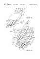
- FIGS. 1 a and 1 bshow perspective views, assembled and exploded, of the main embodiment of the transform
- FIG. 2shows a perspective view of the same transformer, but using contact pads for the primary interconnection.
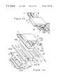
- FIG. 3shows a perspective view of the prior art for a transformer.
- FIG. 4shows a primary winding solution, for each of the internal 4 layers of the PCB.
- FIG. 5shows another solution for the primary windings, for each internal layer.
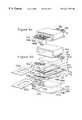
- FIG. 6 ashows another perspective view of the embodiment of the present invention, using power connectors for the primary and secondary, and a mechanical device for both thermal dissipation and mechanical attachment purposes.
- FIG. 6 bshows the exploded view of the embodiment depicted in FIG. 6 a.
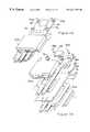
- FIG. 7is another embodiment of the present invention, where the secondary has 4 turns, symmetrical 2 by 2, made out of copper strips, each pair of turns using an attachment solution using specially shaped, bent fins, into designed slots, and soldering over.
- An insulatorinsures electrical separation of the turns.
- FIG. 8shows the embodiment depicted in FIG. 7, from another angle.
- FIGS. 9 a , 9 b and 9 cshow another embodiment of the present invention, with the secondary built on PCB sheets, each turn as a copper layer on each side of the secondary PCB.
- the communicationis made by vias.
- the connectionis obtained with attached, thick copper connectors, shaped as for the main embodiment, but mounted each on opposed sides of the secondary PCB.
- the symmetryis also present between the upper and lower 2 turns on each side of the main PCB.
- FIG. 10shows another embodiment of the present invention, using the layout presented in FIG. 8, but with an additional resonant inductor.
- the resonant inductorhas specific cutouts in the PCB to accommodate the magnetic and padded holes to receive the designed contact pins.
- FIG. 11 ashows another embodiment of the present invention, in exploded view, using the layout presented in FIG. 10, but using designed, specific power connectors for the primary, and direct contact for the secondary.
- FIG. 11 bshows the embodiment of FIG. 11 a in a mounted view.
- FIG. 12 ashows another embodiment of the present invention wherein open loop traces are used to reduce the noise injection between primary and secondary windings.
- FIG. 12 bshows the embodiment of FIG. 12 a in a mounted view.
- FIG. 13shows an embodiment of the invention wherein the secondary winding are embedded in two multilayer PCB and the interconnection between the secondary winding is done via electrically conductive spacer.
- FIGS. 1A and 1Bshow a 3-dimensional view of the preferred embodiment of the present invention, consisting in a transformer made of one multilayer PCB 5 , with internal layers containing the primary windings, two-turn-secondary made of thick copper strips, 11 and 15 , one on each side of the PCB 5 .
- the primaryuses power contacts 7 a and 7 b , which go into the designed metalized holes 17 a and 17 b .
- the primary windingsuse vias 9 a , 9 b , 9 c in order to connect each layer's winding with another layer's winding.
- the secondary stripsuse bent pins 25 f , 25 b , 25 c and 25 a respectively 25 g , 25 e , 25 d and 25 h to mount on the PCB 5 , into specially designed holes: 23 f , 23 b , 23 c and 23 a respectively 23 g , 23 e , 23 b and 23 h .
- the pinsoffer an accurate and rigid positioning of the copper secondary strip on the PCB.
- connection to the secondaryis made with direct contacting the secondary ends, using the holes 13 and 21 , and middle copper spacer 27 between the upper and lower middle tap.
- the magneticsuse an E-type upper 3 and an I-type lower half 1 , which assemble together using the central cut-out 43 in the PCB 5 .
- first layer 122 abetween magnetic core 3 and copper strip 11 and the second layer 122 b between magnetic core 1 and copper strip 15 .
- FIG. 2show a perspective view of another embodiment of the present invention, which uses contact pads 29 a and 29 b , instead of the power connectors 7 a and 7 b in FIG. 1 .
- FIG. 3shows the prior art transformer known before the present invention, as a very complex sandwich of core, seven insulator sheets, and discrete copper strips both for the primary and the secondary windings.
- the sandwichis difficult to prepare and position, the specially shaped spacers require a molding die to manufacture the bobbin, offers limited possibilities in terms of voltage because of the environmental factors related to the primary's winding (humidity, impurities etc.).
- the top E-type magnetics 3is on top, then comes an insulator 31 a , a secondary copper strip 11 , two insulator/spacer sheets 31 b and 31 c , a specially shaped spacer 37 a , a primary turn 33 a , another insulator 31 d , the other primary turn 33 b , another specially shaped spacer 37 b , two insulators 31 e and 31 f , the second secondary turn 15 , another insulator sheet 31 g , and finally they I-type magnetics 1 .
- FIG. 4shows a detail of the preferred embodiment of the present invention, the four windings of the primary, each on a separate, interior layer of the PCB.
- Each layer's windinghas two turns, for a total of 8 turns for the primary.
- the first two turns 39 aleave the contact pad 37 a and go around the cutout in the PCB 43 , ending to the first set of vias 9 a .
- the next two turns 39 bon the next layer, leave the vias 9 a , go around the slot 43 , and end up to the middle set of vias 9 b .
- the third two turns 39 c on the next layergo the same way between vias 9 b and vias 9 c .
- the last two turns on the fourth layer, 39 dextend between the vias 9 c and the connection pad 37 b.
- FIG. 5shows another design for the primary winding of the present invention, using a different location for the vias. Instead of them being aligned, vias 47 a and 47 b are positioned to the right, next to the cutout, via 45 b being close to the edge of the PCB, in the center of side. In this case there will be a insulated layer on top, layer 1 and the insulated layer on the bottom, layer 6 shall cover all the via and comply with the safety agencies foe voltage breakdown.
- FIG. 6shows another embodiment of the present invention in an exploded and an assembled image, where both the primary and the secondary are contacted with power connectors, 51 d , 51 e , 49 d , 49 e , respectively 51 a , 51 b , 51 c , 49 a , 49 b , 49 c .
- the assemblyalso has a U-shaped aluminum part 63 , which covers the E-type magnetics 3 , through a compressible insulator pad 61 .
- the U-shaped partis attached to an aluminum base plate 55 , using four through holes 59 b , 59 a , 59 c , 59 d (not seen in the picture), and threaded holes in the side walls of the U-shaped part.
- Both the U-shaped part 63 and the base-plate 55function both as thermal dissipators and mechanical attachment parts, to mount the sub-assembly to other parts of the equipment, or to a larger heatsink, according to the requirements of the specific application. This mounting may be done using the holes 57 b , 57 a , 57 c , 57 d (not seen in the picture).
- an additional compressible insulator pad 61may be necessary in between the magnetic core 1 , and the base-plate 55 .
- Two insulator pads 122 a and 122 bare placed between copper strip 11 and the magnetic core 3 and respectively between copper strip 15 and magnetic core 1 .
- FIG. 7presents another embodiment of the present invention, with four turns in the secondary winding, two symmetrical turns on each side of the PCB.
- the two turns on one side 11 b and 11 aare separated by an insulator sheet 65 b , except for the area where they meet, clamping together using the bent fins 67 of turns 11 a , and the slots 71 designed to receive the fins in the contact area 69 .
- This areawill also be soldered for better, reliable electrical contact.
- This two-turn-subassemblyis also symmetrical; the one on one side being identical to the one on the other side only flipped 180 degrees.
- the insulator sheet 65 bhas a small hole 65 c , to allow for the pin 25 a of the first secondary loop to go trough. Also the second loop of the secondary 11 a has a small notch 73 a , to the same purpose, not to shorten the first two turns of the secondary winding.
- the pin 25 awill have to go into the hole 23 a of the PCB 5 , where it will be soldered for fastening and securing the upper secondary to the PCB. The same goes for the other side, with pin 25 h , notch 73 b hole 65 d (not seen) and hole 23 h .
- Two additional insulator sheets 122 a and 122 bare placed in between copper strip 15 b and magnetic core 1 , and respectively between copper strip 11 b and magnetic core 3 .
- FIG. 8shows the same embodiment, from another angle.
- FIGS. 9 a , 9 b and 9 cshow another embodiment of the present invention, with the secondary built on thin PCB sheets, each turn as a copper layer on each side of the secondary PCB.
- Each additional secondary PCB 75 ais a double sided PCB with a secondary trace on each side, 77 a and 77 b , making together two turns.
- the communicationis done with the vias 79 a .
- the PCBplays the role of the insulator.
- the connectionare 11 d and 11 c . They are mounted on the corresponding sides of the PCB, so as to be connected at the ends of the two-turn-loop.
- FIG. 10shows another embodiment of the present invention, using the layout presented in FIG. 8, but with an additional resonant inductor composed by magnetic cores 89 and 95 , and winding inside of PCB 85 .
- the resonant inductorhas specific cutouts in the PCB, 87 to accommodate the magnetics, 89 and 95 , and padded holes 91 a and 91 b , to receive the designed contact pins 93 a and 93 b.
- FIGS. 11A and 11Bshows another embodiment of the present invention, using the layout presented in FIG. 10, but using designed, specific power connectors, 7 a and 7 b , for the primary, and direct contact for the secondary.
- FIGS. 12A and 12Bshows another embodiment of the present invention wherein two open turns 105 a and 105 b with a common connection 107 are implemented on the multilayer PCB 101 .
- the common connectionimplemented by a via coated with copper to create an electrical contact between 105 a and 105 b is further connected to a isolation capacitor 113 to a pad 109 .
- a pin 117is connected to the pad 1098 through hole 111 .
- the pin 117can be further connected to a quiet potential.
- a quiet potentialcan be the input DC source or the input GND of the power system wherein the transformer structure is employed.
- the role of the open loop 105 b and 105 bis to create a shield between the primary and secondary.
- the voltage created by the magnetic filed in the transformerwill have similar amplitude but opposite polarities on the 105 a and 105 b . As a result the voltage induced by 105 a and 105 b in the secondary windings 11 and 15 will cancel each other.
- the capacitor 113is there to ensure voltage insulation in compliance with the safety agencies requirements. In some applications several capacitors in series may be required.
- the use of the open turns 105 a and 105 b with a common connection to a quiet potentialcreates a noise cancellation circuit designed to reduce the noise transfer between the primary and secondary winding of the transformer.
- FIG. 13shows another embodiment of the present invention wherein the secondary winding are implemented into the layers of the multilayer PCB, 130 .
- the secondary windingcan have a larger number of turns, easily implemented in the multilayer PCB 130 .
- the primary PCB 5gets sandwiched in between two secondary PCB, 130 , one flipped to each other in a such way that the middle metalized hole 134 a aligns with 134 b , departed by the spacer 136 .
- Two additional isolated sheets 122 a and 122 bwill be placed in between the secondary PCB and the magnetic core for insulation and also to apply a mechanical pressure of the ensemble.
Landscapes
- Engineering & Computer Science (AREA)
- Power Engineering (AREA)
- Coils Or Transformers For Communication (AREA)
Abstract
Description
Claims (23)
Priority Applications (1)
| Application Number | Priority Date | Filing Date | Title |
|---|---|---|---|
| US09/316,924US6211767B1 (en) | 1999-05-21 | 1999-05-21 | High power planar transformer |
Applications Claiming Priority (1)
| Application Number | Priority Date | Filing Date | Title |
|---|---|---|---|
| US09/316,924US6211767B1 (en) | 1999-05-21 | 1999-05-21 | High power planar transformer |
Publications (1)
| Publication Number | Publication Date |
|---|---|
| US6211767B1true US6211767B1 (en) | 2001-04-03 |
Family
ID=23231310
Family Applications (1)
| Application Number | Title | Priority Date | Filing Date |
|---|---|---|---|
| US09/316,924Expired - LifetimeUS6211767B1 (en) | 1999-05-21 | 1999-05-21 | High power planar transformer |
Country Status (1)
| Country | Link |
|---|---|
| US (1) | US6211767B1 (en) |
Cited By (73)
| Publication number | Priority date | Publication date | Assignee | Title |
|---|---|---|---|---|
| US6369685B1 (en)* | 1997-07-10 | 2002-04-09 | Melcher A.G. | Multi-layer planar inductance coil and a method for producing the same |
| US6489878B2 (en)* | 1999-05-11 | 2002-12-03 | Nokia Networks Oy | Method of manufacturing a magnetic power component and a magnetic power component |
| US6559750B2 (en)* | 2000-07-28 | 2003-05-06 | Murata Manufacturing Co., Ltd. | Transformer and electrical device using the same |
| US6583703B2 (en)* | 2001-06-20 | 2003-06-24 | Koninklijke Philips Electronics N.V. | Electrical apparatus having an electromagnetic device operable at multiple inductance values |
| WO2004003947A1 (en) | 2002-06-26 | 2004-01-08 | Premo, S.A. | Method of producing planar transformers and planar transformer thus produced |
| WO2004025671A3 (en)* | 2002-09-16 | 2004-06-10 | Flex Multi Fineline Electronix | Electronic transformer/inductor devices and methods for making same |
| US6774757B2 (en)* | 2002-05-27 | 2004-08-10 | Sansha Electric Manufacturing Company, Limited | Coil |
| US20050017054A1 (en)* | 2003-07-23 | 2005-01-27 | Tom Iverson | Flyback transformer wire attach method to printed circuit board |
| US20050034297A1 (en)* | 2000-05-19 | 2005-02-17 | Harding Philip A. | Slot core transformers |
| US6879235B2 (en)* | 2002-04-30 | 2005-04-12 | Koito Manufacturing Co., Ltd. | Transformer |
| US20050093672A1 (en)* | 2000-09-22 | 2005-05-05 | Harding Philip A. | Electronic transformer/inductor devices and methods for making same |
| US20050195060A1 (en)* | 2004-03-08 | 2005-09-08 | Chiang Man-Ho | Multi-layer printed circuit board inductor winding with added metal foil layers |
| US20050242916A1 (en)* | 2004-04-30 | 2005-11-03 | So Kelvin W C | Low noise planar transformer |
| US20050270745A1 (en)* | 2004-06-04 | 2005-12-08 | Kanghua Chen | Integration of planar transformer and/or planar inductor with power switches in power converter |
| US20050270806A1 (en)* | 2004-06-04 | 2005-12-08 | Ballard Power Systems Corporation | Interleaved power converter |
| US20060152322A1 (en)* | 2004-12-07 | 2006-07-13 | Whittaker Ronald W | Miniature circuitry and inductive components and methods for manufacturing same |
| US20060152326A1 (en)* | 2005-01-12 | 2006-07-13 | Medtronic, Inc. | Integrated planar flyback transformer |
| US20060152085A1 (en)* | 2004-10-20 | 2006-07-13 | Fred Flett | Power system method and apparatus |
| US20060291216A1 (en)* | 2005-06-14 | 2006-12-28 | Blumel Daniel M | Apparatus for reducing in size an igniter circuit and assembly |
| US20070016340A1 (en)* | 2005-06-30 | 2007-01-18 | Christophe Soudier | Controller method, apparatus and article suitable for electric drive |
| US20070040515A1 (en)* | 2005-08-17 | 2007-02-22 | Blumel Daniel M | Apparatus and method for maximizing the longevity of arc tube bulbs during pulsing operation |
| US20080012675A1 (en)* | 2004-08-12 | 2008-01-17 | Epcos Ag | Inductive Component For High Currents And Method For The Production Thereof |
| US20080018425A1 (en)* | 2006-07-21 | 2008-01-24 | Delta Electronics, Inc. | Transforming device of power source and transformer thereof |
| US20080218300A1 (en)* | 2004-09-24 | 2008-09-11 | Koninklijke Philips Electronics, N.V. | Transformer |
| US20080231403A1 (en)* | 2007-03-19 | 2008-09-25 | Abc Taiwan Electronics Corp. | Independent planar transformer |
| US7436282B2 (en) | 2004-12-07 | 2008-10-14 | Multi-Fineline Electronix, Inc. | Miniature circuitry and inductive components and methods for manufacturing same |
| WO2008132645A1 (en) | 2007-04-26 | 2008-11-06 | Philips Intellectual Property & Standards Gmbh | Planar transformer with boards |
| US20080297297A1 (en)* | 2007-05-29 | 2008-12-04 | Delta Electronics, Inc. | Conductive winding structure and transformer having such conductive winding structure |
| US20080297300A1 (en)* | 2005-12-16 | 2008-12-04 | Koninklijke Philips Electronics, N.V. | High Voltage Transformer |
| WO2008152616A1 (en)* | 2007-06-11 | 2008-12-18 | Moog Limited | Low-profile transformer |
| US20090309684A1 (en)* | 2008-06-13 | 2009-12-17 | Delta Electronics, Inc. | Transformer and rectifier circuit using such transformer |
| US20100001824A1 (en)* | 2008-07-05 | 2010-01-07 | Keming Chen | Autotransformer using printed wireboard |
| US7645941B2 (en) | 2006-05-02 | 2010-01-12 | Multi-Fineline Electronix, Inc. | Shielded flexible circuits and methods for manufacturing same |
| US20100079229A1 (en)* | 2008-09-26 | 2010-04-01 | Lincoln Global, Inc. | Planar transformer and method of manufacturing |
| US20100079233A1 (en)* | 2008-09-26 | 2010-04-01 | Lincoln Global, Inc. | Planar transformer |
| DE102009011867A1 (en)* | 2009-03-05 | 2010-09-09 | Volkswagen Ag | Inductor for use in e.g. fuel-operated petrol engine, has inductor layers including electrically non-insulated areas that are overlapped with each other, where overlapping areas of inductor layers have offsets |
| US20100328009A1 (en)* | 2009-06-25 | 2010-12-30 | Murata Manufacturing Co., Ltd. | Electronic component |
| KR101009650B1 (en) | 2007-12-13 | 2011-01-19 | 주식회사 웰드라인 | Intensive Planar Transformer |
| FR2954573A1 (en)* | 2009-12-23 | 2011-06-24 | Thales Sa | Planar power transformer for use in chopping converter, has connection stud arranged at periphery of stacking, where connection stud connects turns to cooling unit to evacuate heat generated by transformer |
| CN101651031B (en)* | 2008-08-13 | 2011-07-27 | 台达电子工业股份有限公司 | Combined structure of transformer, system circuit board and auxiliary circuit board |
| CN101609741B (en)* | 2008-06-18 | 2011-10-26 | 台达电子工业股份有限公司 | Transformer structure and its applicable rectification circuit |
| CN101872671B (en)* | 2009-04-06 | 2011-12-21 | 康舒科技股份有限公司 | Plane type electromagnetic induction element and copper sheet winding thereof |
| US20120099346A1 (en)* | 2010-10-22 | 2012-04-26 | Seps Technologies Ab | Converter and an Electronic Equipment Provided with such a Converter |
| US20130069751A1 (en)* | 2011-09-21 | 2013-03-21 | Lg Innotek Co., Ltd. | Transformer |
| US20130278373A1 (en)* | 2012-04-23 | 2013-10-24 | Tdk Corporation | Coil unit, substrate unit and power supply device |
| US20130308348A1 (en)* | 2012-05-15 | 2013-11-21 | Delta Electronics, Inc | Converter |
| US20140063864A1 (en)* | 2012-05-15 | 2014-03-06 | Delta Electronics, Inc. | Electronic device |
| CN103632812A (en)* | 2013-12-14 | 2014-03-12 | 芜湖科伟兆伏电子有限公司 | Heavy-current high-frequency plane inductor and making method thereof |
| US20140109395A1 (en)* | 2009-11-09 | 2014-04-24 | Nucleus Scientific, Llc | Electric coil and method of manufacture |
| GB2512510A (en)* | 2011-12-06 | 2014-10-01 | Isotera Ltd | A coupler for use in a power distribution system |
| US20140292471A1 (en)* | 2013-04-02 | 2014-10-02 | Bao Hui Science & Technology Co., Ltd. | Transformer |
| US20140347154A1 (en)* | 2013-05-21 | 2014-11-27 | Coherent, Inc. | Interleaved planar pcb rf transformer |
| US20150221432A1 (en)* | 2012-05-15 | 2015-08-06 | Delta Electronics, Inc. | Electronic device |
| US9196414B2 (en) | 2012-10-17 | 2015-11-24 | Covidien Lp | Planar transformers having reduced termination losses |
| US9378883B2 (en)* | 2014-09-24 | 2016-06-28 | Chicony Power Technologies Co., Ltd. | Transformer structure |
| US9449746B2 (en) | 2012-10-17 | 2016-09-20 | Covidien Lp | Methods of manufacturing planar transformers |
| US9620278B2 (en) | 2014-02-19 | 2017-04-11 | General Electric Company | System and method for reducing partial discharge in high voltage planar transformers |
| EP3168970A4 (en)* | 2014-07-11 | 2018-03-14 | United Automotive Electronic Systems Co., Ltd. | Integrated copper bar for secondary-side power circuit of power electronic converter |
| WO2018156934A1 (en)* | 2017-02-23 | 2018-08-30 | General Electric Company | Energy converting device, and device for energizing oil exploration device |
| CN105099132B (en)* | 2014-04-30 | 2018-08-31 | 台达电子工业股份有限公司 | Electronic device |
| US20180301269A1 (en)* | 2017-04-12 | 2018-10-18 | Intel Corporation | Inductor with integrated heat dissipation structures |
| CN108735460A (en)* | 2018-05-21 | 2018-11-02 | 江苏晨朗电子集团有限公司 | A kind of electronic transformer of charger and DC to DC converter dual-purpose |
| CN109119230A (en)* | 2018-09-29 | 2019-01-01 | 常州索维尔电子科技有限公司 | Power transformer structure |
| USRE47423E1 (en) | 2015-04-23 | 2019-06-04 | Chicony Power Technology Co., Ltd. | Integrated power-converting module |
| KR20190114412A (en)* | 2018-03-30 | 2019-10-10 | 엘지이노텍 주식회사 | Clip combined transformer |
| CN110444373A (en)* | 2018-05-02 | 2019-11-12 | 联宝电子股份有限公司 | Magnetic induction component and its manufacturing method |
| US10476360B2 (en) | 2016-09-13 | 2019-11-12 | Indigo Technologies, Inc. | Axial flux motor having rotatably coupled coil stator assemblies and methods of using same |
| US10770981B2 (en) | 2015-04-23 | 2020-09-08 | Chicony Power Technology Co., Ltd. | Voltage conversion module and bobbin |
| CN112185664A (en)* | 2020-10-28 | 2021-01-05 | 济南安海半导体有限公司 | Copper product and cost of labor's novel transformer are practiced thrift |
| WO2021101350A1 (en)* | 2019-11-22 | 2021-05-27 | 박찬웅 | Planar transformer and power supply |
| CN114121442A (en)* | 2021-11-05 | 2022-03-01 | 西安交通大学 | Low-alternating-current copper loss planar magnetic part winding for power electronic converter |
| US11387678B2 (en)* | 2019-09-27 | 2022-07-12 | Apple Inc. | Stacked resonant structures for wireless power systems |
| WO2024103396A1 (en)* | 2022-11-18 | 2024-05-23 | Innoscience (Shenzhen) Semiconductor Co., Ltd. | Power converter and method for manufacturing the same |
Citations (8)
| Publication number | Priority date | Publication date | Assignee | Title |
|---|---|---|---|---|
| US4692604A (en)* | 1984-10-25 | 1987-09-08 | American Telephone And Telegraph Company, At&T Bell Laboratories | Flexible inductor |
| US4873757A (en)* | 1987-07-08 | 1989-10-17 | The Foxboro Company | Method of making a multilayer electrical coil |
| US5161098A (en)* | 1991-09-09 | 1992-11-03 | Power Integrations, Inc. | High frequency switched mode converter |
| JPH06325952A (en)* | 1993-05-14 | 1994-11-25 | Kami Denshi Kogyo Kk | Small transformer for circuit board mount |
| US5469124A (en)* | 1994-06-10 | 1995-11-21 | Westinghouse Electric Corp. | Heat dissipating transformer coil |
| US5760671A (en)* | 1995-09-15 | 1998-06-02 | Celestica Inc. | Transformer with dual flux path |
| US5889660A (en)* | 1997-03-06 | 1999-03-30 | Eaton Corporation | Isolated power supply for indicator light |
| US5929733A (en)* | 1993-07-21 | 1999-07-27 | Nagano Japan Radio Co., Ltd. | Multi-layer printed substrate |
- 1999
- 1999-05-21USUS09/316,924patent/US6211767B1/ennot_activeExpired - Lifetime
Patent Citations (8)
| Publication number | Priority date | Publication date | Assignee | Title |
|---|---|---|---|---|
| US4692604A (en)* | 1984-10-25 | 1987-09-08 | American Telephone And Telegraph Company, At&T Bell Laboratories | Flexible inductor |
| US4873757A (en)* | 1987-07-08 | 1989-10-17 | The Foxboro Company | Method of making a multilayer electrical coil |
| US5161098A (en)* | 1991-09-09 | 1992-11-03 | Power Integrations, Inc. | High frequency switched mode converter |
| JPH06325952A (en)* | 1993-05-14 | 1994-11-25 | Kami Denshi Kogyo Kk | Small transformer for circuit board mount |
| US5929733A (en)* | 1993-07-21 | 1999-07-27 | Nagano Japan Radio Co., Ltd. | Multi-layer printed substrate |
| US5469124A (en)* | 1994-06-10 | 1995-11-21 | Westinghouse Electric Corp. | Heat dissipating transformer coil |
| US5760671A (en)* | 1995-09-15 | 1998-06-02 | Celestica Inc. | Transformer with dual flux path |
| US5889660A (en)* | 1997-03-06 | 1999-03-30 | Eaton Corporation | Isolated power supply for indicator light |
Cited By (138)
| Publication number | Priority date | Publication date | Assignee | Title |
|---|---|---|---|---|
| US6369685B1 (en)* | 1997-07-10 | 2002-04-09 | Melcher A.G. | Multi-layer planar inductance coil and a method for producing the same |
| US6489878B2 (en)* | 1999-05-11 | 2002-12-03 | Nokia Networks Oy | Method of manufacturing a magnetic power component and a magnetic power component |
| US20070124916A1 (en)* | 2000-05-19 | 2007-06-07 | Harding Philip A | Method of making slotted core inductors and transformers |
| US7178220B2 (en) | 2000-05-19 | 2007-02-20 | Multi-Fineline Electronix, Inc. | Method of making slotted core inductors and transformers |
| US7477124B2 (en) | 2000-05-19 | 2009-01-13 | Multi-Fineline Electronix, Inc. | Method of making slotted core inductors and transformers |
| US20050034297A1 (en)* | 2000-05-19 | 2005-02-17 | Harding Philip A. | Slot core transformers |
| US6559750B2 (en)* | 2000-07-28 | 2003-05-06 | Murata Manufacturing Co., Ltd. | Transformer and electrical device using the same |
| US20050093672A1 (en)* | 2000-09-22 | 2005-05-05 | Harding Philip A. | Electronic transformer/inductor devices and methods for making same |
| US6583703B2 (en)* | 2001-06-20 | 2003-06-24 | Koninklijke Philips Electronics N.V. | Electrical apparatus having an electromagnetic device operable at multiple inductance values |
| US6879235B2 (en)* | 2002-04-30 | 2005-04-12 | Koito Manufacturing Co., Ltd. | Transformer |
| US6774757B2 (en)* | 2002-05-27 | 2004-08-10 | Sansha Electric Manufacturing Company, Limited | Coil |
| WO2004003947A1 (en) | 2002-06-26 | 2004-01-08 | Premo, S.A. | Method of producing planar transformers and planar transformer thus produced |
| EP1536436B1 (en)* | 2002-06-26 | 2017-01-25 | Premo, S.L. | Method of producing planar transformers and planar transformer thus produced |
| US20040135662A1 (en)* | 2002-09-16 | 2004-07-15 | Harding Philip A. | Electronic transformer/inductor devices and methods for making same |
| US7135952B2 (en) | 2002-09-16 | 2006-11-14 | Multi-Fineline Electronix, Inc. | Electronic transformer/inductor devices and methods for making same |
| US7277002B2 (en) | 2002-09-16 | 2007-10-02 | Multi-Fineline Electronix, Inc. | Electronic transformer/inductor devices and methods for making same |
| WO2004025671A3 (en)* | 2002-09-16 | 2004-06-10 | Flex Multi Fineline Electronix | Electronic transformer/inductor devices and methods for making same |
| US7696852B1 (en) | 2002-09-16 | 2010-04-13 | Multi-Fineline Electronix, Inc. | Electronic transformer/inductor devices and methods for making same |
| US20070056159A1 (en)* | 2002-09-16 | 2007-03-15 | Harding Philip A | Electronic transformer/inductor devices and methods for making same |
| US20060132276A1 (en)* | 2002-09-16 | 2006-06-22 | Harding Philip A | Electronic transformer/inductor devices and methods for making same |
| US7120492B2 (en) | 2003-07-23 | 2006-10-10 | Cardiac Pacemakers, Inc. | Flyback transformer wire attach method to printed circuit board |
| US20050258925A1 (en)* | 2003-07-23 | 2005-11-24 | Cardiac Pacemakers, Inc. | Flyback transformer wire attach method to printed circuit board |
| US20050017054A1 (en)* | 2003-07-23 | 2005-01-27 | Tom Iverson | Flyback transformer wire attach method to printed circuit board |
| US7225018B2 (en) | 2003-07-23 | 2007-05-29 | Cardiac Pacemakers, Inc. | Flyback transformer wire attach method to printed circuit board |
| US20060284717A1 (en)* | 2003-07-23 | 2006-12-21 | Cardiac Pacemakers, Inc. | Flyback transformer wire attach method to printed circuit board |
| US6927663B2 (en)* | 2003-07-23 | 2005-08-09 | Cardiac Pacemakers, Inc. | Flyback transformer wire attach method to printed circuit board |
| US20050195060A1 (en)* | 2004-03-08 | 2005-09-08 | Chiang Man-Ho | Multi-layer printed circuit board inductor winding with added metal foil layers |
| US7248138B2 (en)* | 2004-03-08 | 2007-07-24 | Astec International Limited | Multi-layer printed circuit board inductor winding with added metal foil layers |
| US20050242916A1 (en)* | 2004-04-30 | 2005-11-03 | So Kelvin W C | Low noise planar transformer |
| US7292126B2 (en) | 2004-04-30 | 2007-11-06 | Astec International Limited | Low noise planar transformer |
| US7289329B2 (en) | 2004-06-04 | 2007-10-30 | Siemens Vdo Automotive Corporation | Integration of planar transformer and/or planar inductor with power switches in power converter |
| US20050270745A1 (en)* | 2004-06-04 | 2005-12-08 | Kanghua Chen | Integration of planar transformer and/or planar inductor with power switches in power converter |
| US20050270806A1 (en)* | 2004-06-04 | 2005-12-08 | Ballard Power Systems Corporation | Interleaved power converter |
| WO2005122375A1 (en)* | 2004-06-04 | 2005-12-22 | Ballard Power Systems Corporation | Interleaved power converter |
| CN100452630C (en)* | 2004-06-04 | 2009-01-14 | 西门子威迪欧汽车电子公司 | Interleaved power converter |
| US7295448B2 (en) | 2004-06-04 | 2007-11-13 | Siemens Vdo Automotive Corporation | Interleaved power converter |
| US20080012675A1 (en)* | 2004-08-12 | 2008-01-17 | Epcos Ag | Inductive Component For High Currents And Method For The Production Thereof |
| US7932799B2 (en) | 2004-09-24 | 2011-04-26 | Koninklijke Philips Electronics N.V. | Transformer |
| US20080218300A1 (en)* | 2004-09-24 | 2008-09-11 | Koninklijke Philips Electronics, N.V. | Transformer |
| US20060152085A1 (en)* | 2004-10-20 | 2006-07-13 | Fred Flett | Power system method and apparatus |
| US20080017404A1 (en)* | 2004-12-07 | 2008-01-24 | Whittaker Ronald W | Miniature circuitry and inductive components and methods for manufacturing same |
| US20060152322A1 (en)* | 2004-12-07 | 2006-07-13 | Whittaker Ronald W | Miniature circuitry and inductive components and methods for manufacturing same |
| US7271697B2 (en) | 2004-12-07 | 2007-09-18 | Multi-Fineline Electronix | Miniature circuitry and inductive components and methods for manufacturing same |
| US7656263B2 (en) | 2004-12-07 | 2010-02-02 | Multi-Fineline Electronix, Inc. | Miniature circuitry and inductive components and methods for manufacturing same |
| US7602272B2 (en) | 2004-12-07 | 2009-10-13 | Multi-Fineline Electronix, Inc. | Miniature circuitry and inductive components and methods for manufacturing same |
| US20090015364A1 (en)* | 2004-12-07 | 2009-01-15 | Whittaker Ronald W | Miniature circuitry and inductive components and methods for manufacturing same |
| US7436282B2 (en) | 2004-12-07 | 2008-10-14 | Multi-Fineline Electronix, Inc. | Miniature circuitry and inductive components and methods for manufacturing same |
| US7690110B2 (en) | 2004-12-07 | 2010-04-06 | Multi-Fineline Electronix, Inc. | Methods for manufacturing miniature circuitry and inductive components |
| US7167074B2 (en) | 2005-01-12 | 2007-01-23 | Medtronic, Inc. | Integrated planar flyback transformer |
| US20060152326A1 (en)* | 2005-01-12 | 2006-07-13 | Medtronic, Inc. | Integrated planar flyback transformer |
| US20060291216A1 (en)* | 2005-06-14 | 2006-12-28 | Blumel Daniel M | Apparatus for reducing in size an igniter circuit and assembly |
| US20070016340A1 (en)* | 2005-06-30 | 2007-01-18 | Christophe Soudier | Controller method, apparatus and article suitable for electric drive |
| US7426099B2 (en) | 2005-06-30 | 2008-09-16 | Continental Automotive Systems Us, Inc. | Controller method, apparatus and article suitable for electric drive |
| US7615941B2 (en) | 2005-08-17 | 2009-11-10 | Blumel Daniel M | Apparatus and method for maximizing the longevity of arc tube bulbs during pulsing operation |
| US20070040515A1 (en)* | 2005-08-17 | 2007-02-22 | Blumel Daniel M | Apparatus and method for maximizing the longevity of arc tube bulbs during pulsing operation |
| US7956714B2 (en)* | 2005-12-16 | 2011-06-07 | Koninklijke Philips Electronics N.V. | High voltage transformer |
| US20080297300A1 (en)* | 2005-12-16 | 2008-12-04 | Koninklijke Philips Electronics, N.V. | High Voltage Transformer |
| US7645941B2 (en) | 2006-05-02 | 2010-01-12 | Multi-Fineline Electronix, Inc. | Shielded flexible circuits and methods for manufacturing same |
| US20080018425A1 (en)* | 2006-07-21 | 2008-01-24 | Delta Electronics, Inc. | Transforming device of power source and transformer thereof |
| US8228152B2 (en)* | 2006-07-21 | 2012-07-24 | Delta Electronics, Inc. | Transforming device of power source and transformer thereof |
| US20080231403A1 (en)* | 2007-03-19 | 2008-09-25 | Abc Taiwan Electronics Corp. | Independent planar transformer |
| US7872560B2 (en)* | 2007-03-19 | 2011-01-18 | Abc Taiwan Electronics Corp. | Independent planar transformer |
| CN101675488B (en)* | 2007-04-26 | 2012-09-05 | 皇家飞利浦电子股份有限公司 | Planar transformer with boards |
| US8378775B2 (en) | 2007-04-26 | 2013-02-19 | Koninklijke Philips Electronics N.V. | Planar transformer with boards |
| US20100253461A1 (en)* | 2007-04-26 | 2010-10-07 | Koninklijke Philips Electronics N.V. | Planar transformer with boards |
| WO2008132645A1 (en) | 2007-04-26 | 2008-11-06 | Philips Intellectual Property & Standards Gmbh | Planar transformer with boards |
| US20080297297A1 (en)* | 2007-05-29 | 2008-12-04 | Delta Electronics, Inc. | Conductive winding structure and transformer having such conductive winding structure |
| WO2008152616A1 (en)* | 2007-06-11 | 2008-12-18 | Moog Limited | Low-profile transformer |
| KR101009650B1 (en) | 2007-12-13 | 2011-01-19 | 주식회사 웰드라인 | Intensive Planar Transformer |
| US7688171B2 (en)* | 2008-06-13 | 2010-03-30 | Delta Electronics, Inc. | Transformer and rectifier circuit using such transformer |
| US20090309684A1 (en)* | 2008-06-13 | 2009-12-17 | Delta Electronics, Inc. | Transformer and rectifier circuit using such transformer |
| CN101609741B (en)* | 2008-06-18 | 2011-10-26 | 台达电子工业股份有限公司 | Transformer structure and its applicable rectification circuit |
| US20100001824A1 (en)* | 2008-07-05 | 2010-01-07 | Keming Chen | Autotransformer using printed wireboard |
| US7859381B2 (en)* | 2008-07-05 | 2010-12-28 | Honeywell International Inc. | Autotransformer using printed wireboard |
| CN101651031B (en)* | 2008-08-13 | 2011-07-27 | 台达电子工业股份有限公司 | Combined structure of transformer, system circuit board and auxiliary circuit board |
| US7859382B2 (en) | 2008-09-26 | 2010-12-28 | Lincoln Global, Inc. | Planar transformer |
| US20100079229A1 (en)* | 2008-09-26 | 2010-04-01 | Lincoln Global, Inc. | Planar transformer and method of manufacturing |
| US8054154B2 (en)* | 2008-09-26 | 2011-11-08 | Linclon Global, Inc. | Planar transformer and method of manufacturing |
| US20100079233A1 (en)* | 2008-09-26 | 2010-04-01 | Lincoln Global, Inc. | Planar transformer |
| DE102009011867A1 (en)* | 2009-03-05 | 2010-09-09 | Volkswagen Ag | Inductor for use in e.g. fuel-operated petrol engine, has inductor layers including electrically non-insulated areas that are overlapped with each other, where overlapping areas of inductor layers have offsets |
| CN101872671B (en)* | 2009-04-06 | 2011-12-21 | 康舒科技股份有限公司 | Plane type electromagnetic induction element and copper sheet winding thereof |
| US20100328009A1 (en)* | 2009-06-25 | 2010-12-30 | Murata Manufacturing Co., Ltd. | Electronic component |
| US8416048B2 (en)* | 2009-06-25 | 2013-04-09 | Murata Manufacturing Co., Ltd. | Electronic component |
| US20140109395A1 (en)* | 2009-11-09 | 2014-04-24 | Nucleus Scientific, Llc | Electric coil and method of manufacture |
| US9934904B2 (en)* | 2009-11-09 | 2018-04-03 | Nucleus Scientific, Inc. | Method and manufacturing an electric coil assembly |
| FR2954573A1 (en)* | 2009-12-23 | 2011-06-24 | Thales Sa | Planar power transformer for use in chopping converter, has connection stud arranged at periphery of stacking, where connection stud connects turns to cooling unit to evacuate heat generated by transformer |
| US20120099346A1 (en)* | 2010-10-22 | 2012-04-26 | Seps Technologies Ab | Converter and an Electronic Equipment Provided with such a Converter |
| US20130069751A1 (en)* | 2011-09-21 | 2013-03-21 | Lg Innotek Co., Ltd. | Transformer |
| US8988179B2 (en)* | 2011-09-21 | 2015-03-24 | Lg Innotek Co., Ltd. | Transformer |
| GB2512510A (en)* | 2011-12-06 | 2014-10-01 | Isotera Ltd | A coupler for use in a power distribution system |
| US10002702B2 (en) | 2011-12-06 | 2018-06-19 | Greengage Lighting Limited | Coupler for use in a power distribution system |
| US8941458B2 (en)* | 2012-04-23 | 2015-01-27 | Tdk Corporation | Coil unit, substrate unit and power supply device |
| US20130278373A1 (en)* | 2012-04-23 | 2013-10-24 | Tdk Corporation | Coil unit, substrate unit and power supply device |
| US20150221432A1 (en)* | 2012-05-15 | 2015-08-06 | Delta Electronics, Inc. | Electronic device |
| CN105186835B (en)* | 2012-05-15 | 2019-07-12 | 台达电子工业股份有限公司 | Electronic device |
| US20140063864A1 (en)* | 2012-05-15 | 2014-03-06 | Delta Electronics, Inc. | Electronic device |
| US9837198B2 (en)* | 2012-05-15 | 2017-12-05 | Delta Electronics, Inc. | Electronic device |
| CN105186835A (en)* | 2012-05-15 | 2015-12-23 | 台达电子工业股份有限公司 | Electronic device |
| US20130308348A1 (en)* | 2012-05-15 | 2013-11-21 | Delta Electronics, Inc | Converter |
| US9484145B2 (en)* | 2012-05-15 | 2016-11-01 | Delta Electronics, Inc | Converter |
| US11616394B2 (en) | 2012-05-15 | 2023-03-28 | Delta Electronics, Inc. | Electronic device |
| US9893536B2 (en)* | 2012-05-15 | 2018-02-13 | Delta Electronics, Inc. | Electronic device |
| US10390876B2 (en) | 2012-10-17 | 2019-08-27 | Covidien Lp | Planar transformers having reduced termination losses |
| US9196414B2 (en) | 2012-10-17 | 2015-11-24 | Covidien Lp | Planar transformers having reduced termination losses |
| US9449746B2 (en) | 2012-10-17 | 2016-09-20 | Covidien Lp | Methods of manufacturing planar transformers |
| US20140292471A1 (en)* | 2013-04-02 | 2014-10-02 | Bao Hui Science & Technology Co., Ltd. | Transformer |
| TWI637412B (en)* | 2013-04-02 | 2018-10-01 | 寶輝科技(龍南)有限公司 | Transformer |
| US20140347154A1 (en)* | 2013-05-21 | 2014-11-27 | Coherent, Inc. | Interleaved planar pcb rf transformer |
| WO2014189771A1 (en)* | 2013-05-21 | 2014-11-27 | Coherent, Inc. | Interleaved planar pcb rf transformer |
| CN103632812A (en)* | 2013-12-14 | 2014-03-12 | 芜湖科伟兆伏电子有限公司 | Heavy-current high-frequency plane inductor and making method thereof |
| CN103632812B (en)* | 2013-12-14 | 2015-11-18 | 芜湖科伟兆伏电子有限公司 | A kind of big current high frequency planar inductance and preparation method thereof |
| US9620278B2 (en) | 2014-02-19 | 2017-04-11 | General Electric Company | System and method for reducing partial discharge in high voltage planar transformers |
| US10236113B2 (en) | 2014-02-19 | 2019-03-19 | General Electric Company | System and method for reducing partial discharge in high voltage planar transformers |
| CN105099132B (en)* | 2014-04-30 | 2018-08-31 | 台达电子工业股份有限公司 | Electronic device |
| US10340076B2 (en) | 2014-07-11 | 2019-07-02 | United Automotive Electronic Systems Co. Ltd. | Integrated copper bar for secondary power circuit of power electronic converter |
| EP3168970A4 (en)* | 2014-07-11 | 2018-03-14 | United Automotive Electronic Systems Co., Ltd. | Integrated copper bar for secondary-side power circuit of power electronic converter |
| US9378883B2 (en)* | 2014-09-24 | 2016-06-28 | Chicony Power Technologies Co., Ltd. | Transformer structure |
| US10951123B2 (en) | 2015-04-23 | 2021-03-16 | Chicony Power Technology Co.. Ltd. | Power conversion system |
| USRE47423E1 (en) | 2015-04-23 | 2019-06-04 | Chicony Power Technology Co., Ltd. | Integrated power-converting module |
| US10770981B2 (en) | 2015-04-23 | 2020-09-08 | Chicony Power Technology Co., Ltd. | Voltage conversion module and bobbin |
| US10476360B2 (en) | 2016-09-13 | 2019-11-12 | Indigo Technologies, Inc. | Axial flux motor having rotatably coupled coil stator assemblies and methods of using same |
| US12170468B2 (en) | 2016-09-13 | 2024-12-17 | Indigo Technologies, Inc. | Multi-bar linkage electric drive system |
| US10483832B2 (en) | 2016-09-13 | 2019-11-19 | Indigo Technologies, Inc. | Multi-bar linkage electric drive system |
| US10644578B2 (en) | 2016-09-13 | 2020-05-05 | Indigo Technologies, Inc. | Guided multi-bar linkage electric drive system |
| US10938285B2 (en) | 2016-09-13 | 2021-03-02 | Indigo Technologies, Inc. | Multi-bar linkage electric drive system |
| US11368076B2 (en) | 2016-09-13 | 2022-06-21 | Indigo Technologies, Inc. | Multi-bar linkage electric drive system |
| WO2018156934A1 (en)* | 2017-02-23 | 2018-08-30 | General Electric Company | Energy converting device, and device for energizing oil exploration device |
| US20180301269A1 (en)* | 2017-04-12 | 2018-10-18 | Intel Corporation | Inductor with integrated heat dissipation structures |
| KR20190114412A (en)* | 2018-03-30 | 2019-10-10 | 엘지이노텍 주식회사 | Clip combined transformer |
| CN110444373A (en)* | 2018-05-02 | 2019-11-12 | 联宝电子股份有限公司 | Magnetic induction component and its manufacturing method |
| CN110444373B (en)* | 2018-05-02 | 2021-12-17 | 联宝电子股份有限公司 | Magnetic induction component and manufacturing method thereof |
| CN108735460A (en)* | 2018-05-21 | 2018-11-02 | 江苏晨朗电子集团有限公司 | A kind of electronic transformer of charger and DC to DC converter dual-purpose |
| CN109119230A (en)* | 2018-09-29 | 2019-01-01 | 常州索维尔电子科技有限公司 | Power transformer structure |
| US11387678B2 (en)* | 2019-09-27 | 2022-07-12 | Apple Inc. | Stacked resonant structures for wireless power systems |
| WO2021101350A1 (en)* | 2019-11-22 | 2021-05-27 | 박찬웅 | Planar transformer and power supply |
| CN112185664A (en)* | 2020-10-28 | 2021-01-05 | 济南安海半导体有限公司 | Copper product and cost of labor's novel transformer are practiced thrift |
| CN114121442A (en)* | 2021-11-05 | 2022-03-01 | 西安交通大学 | Low-alternating-current copper loss planar magnetic part winding for power electronic converter |
| WO2024103396A1 (en)* | 2022-11-18 | 2024-05-23 | Innoscience (Shenzhen) Semiconductor Co., Ltd. | Power converter and method for manufacturing the same |
Similar Documents
| Publication | Publication Date | Title |
|---|---|---|
| US6211767B1 (en) | High power planar transformer | |
| US5565837A (en) | Low profile printed circuit board | |
| US6420953B1 (en) | Multi-layer, multi-functioning printed circuit board | |
| US6353379B1 (en) | Magnetic device employing a winding structure spanning multiple boards and method of manufacture thereof | |
| JP4802615B2 (en) | LC composite parts | |
| US6373736B2 (en) | Isolated converter | |
| JPS63173308A (en) | Transformer | |
| JPH11195543A (en) | Magnetic component assembly | |
| US20200128671A1 (en) | Printed circuit board and motor including the same | |
| CN1926646A (en) | Magnetic part | |
| US4475143A (en) | Decoupling capacitor and method of manufacture thereof | |
| US6380834B1 (en) | Planar magnetic assembly | |
| GB2087656A (en) | Miniaturized transformer construction | |
| JPH06325949A (en) | Structure of electromagnetic circuit | |
| WO2004040599A1 (en) | A circuit board with a planar magnetic element | |
| US20250006415A1 (en) | Power conversion module and magnetic component thereof | |
| JPH05291062A (en) | Thin type transformer and assembling method thereof | |
| US5534838A (en) | Low profile high power surface mount transformer | |
| US12417875B2 (en) | Electronic device | |
| JP2003197439A (en) | Electromagnetic device | |
| JPH07163146A (en) | Dc-dc converter | |
| JPH08293417A (en) | Printed coil component and printed coil board | |
| JP2571389B2 (en) | Stacked hybrid integrated circuit components | |
| JP4802616B2 (en) | LC composite parts | |
| KR100366241B1 (en) | Transformer having thin plate of plane type |
Legal Events
| Date | Code | Title | Description |
|---|---|---|---|
| AS | Assignment | Owner name:ROMPOWER INC., ARIZONA Free format text:ASSIGNMENT OF ASSIGNORS INTEREST;ASSIGNOR:JITARU, IONEL;REEL/FRAME:009997/0262 Effective date:19990521 | |
| STCF | Information on status: patent grant | Free format text:PATENTED CASE | |
| AS | Assignment | Owner name:ASCOM ENERGY SYSTEMS AG, SWITZERLAND Free format text:ASSIGNMENT OF ASSIGNORS INTEREST;ASSIGNOR:ROMPOWER INC.;REEL/FRAME:011700/0932 Effective date:20010202 | |
| FEPP | Fee payment procedure | Free format text:PAYOR NUMBER ASSIGNED (ORIGINAL EVENT CODE: ASPN); ENTITY STATUS OF PATENT OWNER: SMALL ENTITY | |
| AS | Assignment | Owner name:DELTA ENERGY SYSTEMS (SWITZERLAND) AG, SWITZERLAND Free format text:CHANGE OF NAME;ASSIGNOR:ASCOM ENERGY SYSTEMS AG;REEL/FRAME:015083/0089 Effective date:20031209 | |
| FPAY | Fee payment | Year of fee payment:4 | |
| AS | Assignment | Owner name:DET INTERNATIONAL HOLDING LIMITED, CAYMAN ISLANDS Free format text:ASSIGNMENT OF ASSIGNORS INTEREST;ASSIGNOR:DELTA ENERGY SYSTEMS (SWITZERLAND) AG;REEL/FRAME:019111/0447 Effective date:20070130 | |
| FPAY | Fee payment | Year of fee payment:8 | |
| FPAY | Fee payment | Year of fee payment:12 |