US6210370B1 - Access device with expandable containment member - Google Patents
Access device with expandable containment memberDownload PDFInfo
- Publication number
- US6210370B1 US6210370B1US08/781,273US78127397AUS6210370B1US 6210370 B1US6210370 B1US 6210370B1US 78127397 AUS78127397 AUS 78127397AUS 6210370 B1US6210370 B1US 6210370B1
- Authority
- US
- United States
- Prior art keywords
- expandable
- obturator
- distal
- access device
- tube
- Prior art date
- Legal status (The legal status is an assumption and is not a legal conclusion. Google has not performed a legal analysis and makes no representation as to the accuracy of the status listed.)
- Expired - Lifetime
Links
- 239000000463materialSubstances0.000claimsdescription52
- 238000003780insertionMethods0.000claimsdescription21
- 230000037431insertionEffects0.000claimsdescription21
- 230000001225therapeutic effectEffects0.000claimsdescription20
- 238000000034methodMethods0.000claimsdescription17
- 239000007787solidSubstances0.000claimsdescription17
- 210000004204blood vesselAnatomy0.000claimsdescription14
- 208000007536ThrombosisDiseases0.000claimsdescription8
- 208000005189EmbolismDiseases0.000claimsdescription4
- 230000004927fusionEffects0.000claimsdescription4
- 230000006835compressionEffects0.000claimsdescription3
- 238000007906compressionMethods0.000claimsdescription3
- 239000012530fluidSubstances0.000claimsdescription2
- 238000011065in-situ storageMethods0.000claims3
- 230000002441reversible effectEffects0.000description14
- 238000005452bendingMethods0.000description9
- 230000001419dependent effectEffects0.000description5
- 238000013156embolectomyMethods0.000description4
- 230000008901benefitEffects0.000description3
- 230000003247decreasing effectEffects0.000description3
- 239000008280bloodSubstances0.000description2
- 210000004369bloodAnatomy0.000description2
- 238000010276constructionMethods0.000description2
- 239000006185dispersionSubstances0.000description2
- 230000009977dual effectEffects0.000description2
- 239000013536elastomeric materialSubstances0.000description2
- 238000004519manufacturing processMethods0.000description2
- 230000007246mechanismEffects0.000description2
- 230000005012migrationEffects0.000description2
- 238000013508migrationMethods0.000description2
- 239000003351stiffenerSubstances0.000description2
- 238000013151thrombectomyMethods0.000description2
- 230000032258transportEffects0.000description2
- 208000031481Pathologic ConstrictionDiseases0.000description1
- 208000002847Surgical WoundDiseases0.000description1
- 230000009471actionEffects0.000description1
- 230000001154acute effectEffects0.000description1
- 238000010420art techniqueMethods0.000description1
- 230000004888barrier functionEffects0.000description1
- 230000008859changeEffects0.000description1
- 239000011248coating agentSubstances0.000description1
- 238000000576coating methodMethods0.000description1
- 239000002131composite materialSubstances0.000description1
- 238000000502dialysisMethods0.000description1
- 238000012377drug deliveryMethods0.000description1
- 238000010438heat treatmentMethods0.000description1
- 208000014674injuryDiseases0.000description1
- 230000004048modificationEffects0.000description1
- 238000012986modificationMethods0.000description1
- 230000008569processEffects0.000description1
- 229920005573silicon-containing polymerPolymers0.000description1
- 230000002966stenotic effectEffects0.000description1
- 238000006467substitution reactionMethods0.000description1
- 230000008733traumaEffects0.000description1
Images


Classifications
- A—HUMAN NECESSITIES
- A61—MEDICAL OR VETERINARY SCIENCE; HYGIENE
- A61B—DIAGNOSIS; SURGERY; IDENTIFICATION
- A61B17/00—Surgical instruments, devices or methods
- A61B17/22—Implements for squeezing-off ulcers or the like on inner organs of the body; Implements for scraping-out cavities of body organs, e.g. bones; for invasive removal or destruction of calculus using mechanical vibrations; for removing obstructions in blood vessels, not otherwise provided for
- A61B17/22031—Gripping instruments, e.g. forceps, for removing or smashing calculi
- A61B17/22032—Gripping instruments, e.g. forceps, for removing or smashing calculi having inflatable gripping elements
- A—HUMAN NECESSITIES
- A61—MEDICAL OR VETERINARY SCIENCE; HYGIENE
- A61B—DIAGNOSIS; SURGERY; IDENTIFICATION
- A61B17/00—Surgical instruments, devices or methods
- A61B17/22—Implements for squeezing-off ulcers or the like on inner organs of the body; Implements for scraping-out cavities of body organs, e.g. bones; for invasive removal or destruction of calculus using mechanical vibrations; for removing obstructions in blood vessels, not otherwise provided for
- A61B17/221—Gripping devices in the form of loops or baskets for gripping calculi or similar types of obstructions
- A61B2017/2215—Gripping devices in the form of loops or baskets for gripping calculi or similar types of obstructions having an open distal end
Definitions
- the present inventionrelates generally to devices for removing obstructing material from body passages and, more particularly, to an access device configurable between a first small diameter for initial insertion into a body passage and a second larger diameter for effecting the removal of obstructing material.
- obstructing materialsmay include plaque, thrombus, embolus, clots, and fatty deposits. In other cases, obstructions may result from stones and strictures.
- Cathetersare commonly inserted into vessels for the purpose of dislodging obstructing materials from the vessel walls.
- a balloon tipped catheteris introduced through a surgical incision and into a blood vessel.
- the balloon tipped catheteris advanced to the location of the obstructing material or occlusion, and the balloon is then inflated at a point within the vessel beyond the point of the obstructing material.
- the catheter including the attached balloonis then pulled back to the point of insertion. In this manner, the balloon pushes the obstructing material to the point of insertion where it is removed through the incision.
- a problem associated with this embolectomy techniqueinvolves the efficient collection and removal of obstructing material while preventing migration and dispersion of the obstructing material.
- Other percutaneous proceduresexist in the prior art for recanalization of vessels.
- One percutaneous procedureinvolves the use of laser energy to vaporize the stenotic material.
- Another percutaneous procedurecommonly referred to as aspiration embolectomy/thrombectomy, relies on a negative pressure to collect the obstructing material.
- Percutaneous or minimally invasive access to a blood vessel in the case of a balloon catheterrequires the catheter to have a very small diameter to fit through a corresponding small incision in the blood vessel. Once the catheter is in the blood vessel, however, portions of the catheter need to assume a large profile removal interface for efficient removal of the obstructing material from the lumen of the blood vessel.
- U.S. Pat. No. 5,011,488 to Ginsburgdiscloses the use of an expanding funnel-shaped sheath for use in withdrawing thrombus or embolus (obstructing material) from a blood vessel.
- the funnelis deployed by extending the expanding tunnel-shaped sheath from within a second sheath to thereby allow the compressed funnel to expand radially.
- Use of this second sheathtends to increase the overall diameter of the device, thus increasing the size of the incision required for insertion of the device.
- this deviceIn addition to not achieving an optimally small insertion diameter, this device is also unable to obtain an optimally large intraluminal operating diameter. An optimally large intraluminal operating diameter would allow for better insertion and removal of larger instruments through the sheath.
- This prior art technique of inserting both the introducer sheath and the pre-shaped funnel sheath into the body passage, and of subsequently removing the introducer sheathrequires the large introduction incision to form a seal around the smaller diameter pre-shaped funnel sheath after the introducer sheath is removed.
- the double sheath combination of the prior artrequires an initial incision into the body passage large enough to accommodate the introducer sheath and, subsequently, small enough to adequately form a seal around the smaller pre-formed funnel sheath left in place after the introducer sheath is removed. Since the initial incision cannot be subsequently reduced in size to accommodate the funnel sheath, a good seal in this prior art system is difficult to obtain.
- U.S. Pat. No. 5,234,425 to Fogartydiscloses a variable diameter sheath constructed of a composite elastomeric material that may be stretched to reduce the diameter. This variable diameter sheath, however, is not used for the removal of obstructing material.
- the primary goal of this deviceis to provide a lining of a body passage with a thin walled single thickness interior sheath, which is introduced into the body passage in a reduced diameter condition and subsequently expanded to snugly fit the interior wall of the body passage.
- the variable diameter sheathincorporates a tubular braid encapsulated within a coating of high elongation silicone polymer.
- the access device of the present inventiondoes not require an initial large incision to subsequently form a seal around a smaller-diameter funnel shaped sheath.
- the access device of the present inventionis insertable into a body passage or duct using a minimally invasive technique.
- a distal portion of the access device of the present inventionmay be enlarged in diameter, while the diameter of the portion contacting the incision area of the blood vessel remains constant.
- the access devicefits through an optimally small incision within the blood vessel, and the portion of the access device contacting the incision area of the blood vessel does not change in diameter, thus providing an effective seal.
- the enlarged diameter of the distal portion of the access devicemay comprise any of a variety of predetermined shapes and sizes, depending upon the specific needs required by a given procedure.
- the distal end of the access devicemay assume the shape of a forward facing funnel to provide a mechanism for withdrawing obstructing material from the body passage.
- a single sheath having an optimally minimum diameteris inserted through an incision in a body passage.
- the single sheath of the access deviceis inserted into the body passage incision with the expandable containment member of the access device in a minimum diameter configuration.
- the expandable containment memberis held in the minimum diameter configuration using structure other than the large-diameter external sheath of the prior art.
- the structure used by the present invention for configuring the expandable containment member to a minimum diametercan subsequently be removed from the lumen of the access device, once the expandable containment member has been expanded.
- the mechanism for configuring the expandable containment memberdoes not increase the outside diameter of the access device. When the structure for configuring the expandable containment member in the small diameter configuration is no longer needed, it can be removed from the body passage without affecting the outside diameter of the access device near the incision in the body passage.
- the access deviceincludes an outer tube having a proximal tube end and a distal tube end, and a lumen extending between the proximal tube end and the distal tube end.
- An obturator assemblyhaving a proximal obturator end and a distal obturator end is removably and concentrically disposed within the lumen of the outer tube.
- An expandable containment memberhaving a proximal member end and a distal member end is connected to both the distal tube end and the distal obturator end. The proximal member end is connected to the distal tube end, and the distal member end is detachably connected to the distal obturator end.
- the expandable containment membercan be expanded by relative movement between the proximal member end and the distal member end. This relative movement corresponds to relative movement of the outer tube and the obturator assembly in opposite directions.
- the proximal member end of the expandable containment memberis held away from the distal member end of the expandable containment member, to thereby hold the expandable containment member in an unexpanded state.
- the proximal member end and the distal member endare moved together to expand the expandable containment member.
- the obturator assemblycan then be removed from the access device, to thereby provide an unobstructed lumen within the outer tube.
- the lumen of the outer tubecan then facilitate insertion and removal of instruments and materials.
- a therapeutic balloon cathetercan be inserted into the lumen to facilitate removal of embolus or thrombus.
- the access device of the present inventionfurther includes a guidewire, which is adapted to be inserted through the obturator assembly.
- the guidewireacts as a stiffener and as a leader for the access device.
- the outer tube of the access devicehas a predetermined outer diameter and an axis extending between the proximal tube end and the distal tube end.
- the expandable containment memberis attached to the outer tube at the distal tube end, and has an unexpanded diameter that is generally equal to the outer diameter of the outer tube.
- the outer tubemay include a solid walled tubular member, and the expandable containment member may include a braided tubular component.
- the solid walled tubular member and the expandable containment memberare joined together by bonding or fusion, and the expandable containment member may be coated with a non-permeable elastomeric material that forms a barrier to flow within the body passage when the expandable containment member is expanded.
- the obturator assembly of the present inventionis initially connected to the expandable containment member to facilitate insertion of the access device into the body passage.
- the obturator assemblyis disconnected from this expandable containment member after insertion of the access device, to thereby facilitate movement of the obturator assembly within the expandable containment member.
- the obturator assembly of the present inventionincludes an intermediate slidable obturator sleeve having a proximal intermediate sleeve end and a distal intermediate sleeve end.
- a lumenextends between the proximal intermediate sleeve end and the distal intermediate sleeve end.
- An inner fixed obturator sleevehas a proximal inner sleeve end and a distal inner sleeve end, and is concentrically disposed within the lumen of the intermediate slidable obturator sleeve.
- the obturatorfurther includes an obturator expandable cone, which has a proximal cone end and a distal cone end. The distal cone end is connected to the distal inner sleeve end, and the proximal cone end is connected to the distal intermediate sleeve end.
- the obturator expandable conecan be expanded by relative movement between the proximal cone end and the distal cone end, which is affected by relative movement of the distal inner sleeve end and the distal intermediate sleeve end in opposite directions.
- the obturator expandable coneOnce the obturator expandable cone has been expanded, the obturator is moved proximally against the expandable containment member, to thereby compress the expandable containment member about an axis of the expandable containment member.
- the expandable containment memberbends about a mid-point of the expandable containment member located between the proximal member end and the distal member end.
- the expandable containment memberforms a cone when the proximal member end is moved sufficiently close to the distal member end, and when the distal member end is moved proximally past the mid-point of the expandable containment member.
- a tubular access deviceis inserted into the body passage, and the tubular access device is moved in a distal direction within the body passage to a first location where obstructing material is located within the body passage.
- the distal end of the expandable containment memberis moved toward the proximal end of the expandable containment member, to thereby expand the expandable containment member into a cone shape having a relatively large diameter.
- the obturator assembly of the access deviceis removed from the lumen of the outer tube, and a therapeutic catheter is inserted into the outer tube, and moved in the distal direction past the first location within the body passage, to a second location on the distal side of the obstructing material.
- the therapeutic catheteris expanded, and is then retracted in a proximal direction from the second location toward the expandable containment member. Movement of the expanded therapeutic catheter in the proximal direction transports the obstructing material into the expandable containment member and then into the lumen of the outer tube.
- the obturator assemblyis inserted back into the lumen of the outer tube and used to collapse the expandable containment member into a low-diameter configuration.
- the access deviceis then removed from the body passage with the expandable containment member in the low-profile configuration.
- a containment regionis formed interiorly of the access device and exteriorly of the catheter.
- This containment regionhas a volume which is dependent on the inside diameter of the access device and the outside diameter of the catheter. It has been found advantageous to provide this containment region with a large volume in order to accommodate a large portion of the obstruction material with each operation of the catheter. The larger the volume, the fewer operations of the catheter are required in order to fully remove the obstruction.
- the volume of this containment regioncan be increased by decreasing the outside diameter of the catheter.
- the catheteris dependent on a large diameter in order to increase its maneuverability, such as its pushability and steerability.
- a tapered catheterhas been found particularly advantageous in meeting these dual requirements.
- the tapered catheter disclosed and claimed by applicant in U.S. patent application Ser. No. 08/303,427 filed on Sep. 9, 1994 and entitled Embolectomy Catheter and Method of Making Samecan be used in a preferred combination. This application is incorporated herein by reference.
- a further aspect of the inventionincludes a combination adapted for removing an obstruction from a body passage.
- the combinationincludes an access device having the configuration of a tube with a proximal end, and a distal end having a first internal diameter.
- a catheter with a proximal end of a second external diameter and a distal end of a third external diameteris insertable into the tube where the distal end of the tube and the distal end of the catheter define a containment region having a volume dependent on the first internal diameter and the third external diameter.
- An engagement structureis disposed at the distal end of the catheter.
- the catheteris maneuverable distally through the tube to position the engagement structure on the side of the obstruction opposite the access device and is further moveable proximally to draw the obstruction into the containment region.
- the second diameter of the catheteris greater than the third diameter of the catheter to increase the maneuverability of the catheter without decreasing the volume of the containment region.
- the inventionincludes a method for removing an obstruction from a body passage.
- the methodincludes the steps of providing an access device having a lumen extending between a proximal end and a distal end with a first internal diameter. This access device is inserted through the body passage to a position proximal of the obstruction.
- a catheteris provided having a shaft with a proximal end of a second diameter and a distal end of a third diameter, and an engagement structure disposed at the distal end of the shaft.
- the catheteris positioned in the lumen of the access device to define a containment region between the distal end of the device and the distal end of the catheter. This containment region has a volume dependent on the first internal diameter and the third external diameter.
- the cathetercan then be maneuvered distally through the lumen of the access device to position the engagement structure distally of the obstruction. Maneuvering the catheter proximally draws the obstruction into the containment region defined by the access device and the catheter.
- the catheteris formed with the second diameter of its proximal end larger than the third diameter of its distal end in order to increase the maneuverability of the catheter without decreasing the volume of the containment region.
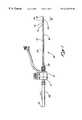
- FIG. 1is a side view of the assembled access device according to the presently preferred embodiment
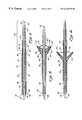
- FIG. 2is a side view of the sheath assembly according to the presently preferred embodiment
- FIG. 3is a side view of the obturator assembly according to the presently preferred embodiment
- FIG. 4is a cross-sectional view of the access device in the introductory profile and unexpanded condition according to the presently preferred embodiment
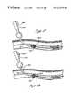
- FIG. 5is a cross-sectional view of the deployed access device showing the obturator expandable cone expanding the expandable containment member of the access device according to the presently preferred embodiment
- FIG. 6is a cross-sectional view of the deployed access device showing the obturator expandable cone in an unexpanded condition according to the presently preferred embodiment
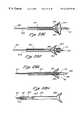
- FIG. 7is a view of access device with the obturator removed and with the expandable containment member fully deployed according to the presently preferred embodiment
- FIG. 8is a side view of the access device with the obturator assembly removed and the expandable containment member deployed;
- FIG. 9is a cross-sectional view of a first alternative embodiment of the present invention in the introductory profile
- FIG. 10is a cross-sectional view of the first alternative embodiment of the present invention showing the expandable containment member partially deployed;
- FIG. 11is a cross-sectional view of the first alternative embodiment of the present invention showing the expandable containment member fully deployed;
- FIG. 12is a cross-sectional view of the first alternative embodiment of the present invention with the obturator assembly removed and the expandable containment member fully deployed;
- FIGS. 13 A-Gare cross-sectional sequential views of a second alternative embodiment of the present invention illustrating the sequence of expansion and deployment;
- FIGS. 14 A-Dare cross-sectional views of a third alternative embodiment of the present invention showing the sequence of deployment of the expandable containment member
- FIG. 15is a view of the presently preferred embodiment inserted within a body passage
- FIG. 16is a view of the presently preferred embodiment inserted within a body passage with the obturator expandable cone deployed;
- FIG. 17is a view of the access device of the presently preferred embodiment inserted within a body passage showing the obturator assembly opening the expandable containment member;
- FIG. 18is a view of the access device of the presently preferred embodiment inserted within a body passage showing the obturator assembly in the removal profile;
- FIG. 19is a view of the access device of the presently preferred embodiment inserted within a body passage showing the expandable containment member in the open condition with the obturator assembly removed and with a therapeutic balloon catheter inserted;
- FIG. 20is a view of the access device of the presently preferred embodiment inserted within a body passage illustrating the use of a balloon catheter through the access device to treat an occlusion;
- FIG. 21is a view of the access device of the presently preferred embodiment in use within a body passage as a balloon catheter withdraws an occlusive mass toward the expandable containment member of the access device;
- FIG. 22illustrates the containment of an occlusive mass within the expandable containment member according to the presently preferred embodiment
- FIG. 23is a view of the expanded containment member of the access device of the presently preferred embodiment with the balloon catheter removed;
- FIG. 24is a view of the access device of the presently preferred embodiment showing the obturator assembly being re-inserted to collapse the expandable containment member for removal from the body passage;
- FIG. 25is a view of the collapsed expandable containment member and obturator assembly of the presently preferred embodiment, prior to removal from a body passage;
- FIG. 26is a view of a body passage with the access device of the presently preferred embodiment removed;
- FIG. 27 A-Jare cross-sectional sequential views of a fourth alternative embodiment of the present invention showing the sequence of deployment of an expandable containment member
- FIG. 28 A-Hare cross-sectional sequential views of a fifth alternative embodiment of the present invention showing the sequence of deployment of an expandable containment member
- FIG. 29is an axial cross section view of a further embodiment of the combination including an access device and therapeutic catheter, this view being similar to FIG. 22 but illustrating the therapeutic catheter in the form of a tapered catheter;
- FIG. 30is an enlarged axial cross section of the combination illustrated in FIG. 29.
- FIG. 31is a radial cross section view of the combination of the access device and tapered catheter taken along lines 31 — 31 of FIG. 30 .
- an access device 30 of the present inventionis illustrated having a sheath assembly 32 , as best seen in FIG. 2, and an obturator assembly 34 , as best seen in FIG. 3, inserted through the sheath assembly 32 .
- the sheath assembly 32comprises an outer flexible tube 36 having a proximal tube end 38 and a distal tube end 41 .
- the sheath assembly 32further comprises an accessory device 45 and an expandable containment member 43 , which is connected to the outer flexible tube 36 near the distal tube end 41 .
- the obturator assembly 34comprises a proximal obturator end 47 and a distal obturator end 50 .
- the obturator end area 52includes an obturator expandable cone 54 and a proximal portion 56 .
- the expandable containment member 43 of the sheath assembly 32is connected to the proximal portion 56 of the obturator end area 52 .
- An obturator handle 58 of the obturator assembly 34is connected to the accessory device 45 of the sheath assembly 32 via a handle connector 61 .
- the outer flexible tube 36 of the sheath assembly 32comprises the expandable containment member 43 and a connector portion 63 .
- the portion of the outer flexible tube 36 located between the expandable containment member 43 and the connector portion 63preferably comprises a semi-rigid portion of solid walled tubing, and the expandable containment member 43 preferably comprises a braided tubular component.
- the expandable containment member 43is preferably joined to this solid walled tubular member by either bonding or fusion. As presently embodied, the expandable containment member 43 is bonded to the solid walled tubular portion using thermal fusion.
- the connector portion 63preferably comprises a solid plastic component, which is connected to the solid walled tubular portion of the outer flexible tube 36 .
- the connector portion 63removably connects the outer flexible tube 36 to the tube connector 67 of the accessory device 45 .
- the connector portion 63comprises threads (not shown) which fit into the tube connector 67 for a snug fit.
- a lumenis formed within the outer flexible tube 36 between the distal tube end 41 and the proximal tube end 38 .
- This lumenis preferably sized and configured to accommodate a shaft portion of the obturator assembly 34 (FIG. 3 ).
- the lumen of the outer flexible tube 36may also removably accommodate other instruments.
- a side port 70 of the sheath assembly 32is adapted for applying/removing air or fluid to/from the lumen of the outer flexible tube 36 , under either positive or negative pressure. Instruments, such as the obturator assembly 34 (FIG. 3) can be inserted through the handle connector 61 of the sheath assembly 32 and out of the expandable containment member 43 , for example.
- Finger tabs 71 of the accessory device 45operate to open and seal access to the lumen of the outer flexible tube 36 , depending on the configuration of the two finger tabs 71 .
- the obturator assembly 34comprises an obturator shaft 72 , which comprises the obturator end area 52 and which is connected to the obturator handle 58 via a connector portion 74 .
- the obturator expandable cone 54can be radially expanded and contracted by movement of the slidable actuator 76 .
- the distal obturator end 50 of the obturator assembly 34is inserted through the handle connector 61 of the sheath assembly 32 . The distal obturator end is then moved through the lumen of the outer flexible tube 36 , and out of the expandable containment member 43 of the sheath assembly 32 .
- the connector portion 74 of the obturator assembly 34accommodates threads of the handle connector 61 therein.
- the obturator end area 52extends distally out of the expandable containment member 43 of the sheath assembly 32 .
- FIG. 4is a cross-sectional view of the access device 30 of the present invention configured in an introductory profile, unexpanded condition.
- the lumen 78 of the outer flexible tube 36is shown having a guidewire 81 inserted therethrough.
- the guidewire 81operates as both a stiffener and a leader for the access device 30 , during insertion of the access device 30 into a body passage, for example.
- the guidewire 81provides strength to the access device 30 , and allows for manufacturing of the outer flexible tube 36 and the obturator shaft 72 components in lightweight and thin-walled constructions in order to conserve space within the body passage.
- the use of the guidewire 81also serves to reduce the strength requirements of the outer flexible tube 36 and the obturator shaft 72 components during insertion and deployment of the expandable members 43 and/or 54 .
- the expandable containment member 43comprises a proximal member end 83 and a distal member end 85 .
- the proximal member end 83 of the expandable containment member 43is preferably bonded to the solid walled portion of the flexible tube 36 , and the distal member end 85 of the expandable containment member 43 is bonded, via a bonded portion 87 , around the obturator shaft 72 .
- the outer slidable obturator sleeve 90is preferably fused to the distal member end 85 of the expandable containment member 43 at the bonded portion 87 .
- the outer slidable obturator sleeve 90is fused to the tubular mesh of the expandable containment member 43 by heating the outer flexible tube 36 and the expandable containment member 43 while holding them in compression and over an inserted mandrel. This construction results in no substantial buildup of material in the bonded portion 87 and a minimum increase of diameter in the bonded portion 87 .
- the outer flexible tube 36 materialis forced to flow into the woven material of the expandable containment member 43 and into and around the individual woven elements thereof.
- the woven material of the expandable containment member 43is subsequently folded back to form a bending area 107 in the woven mesh of the expandable containment member 43 , and extended proximally to overlap the distal tube end 41 of the outer flexible tube 36 .
- the proximal member end 83 of the expandable containment member 43is fused to the outer flexible tube 36 in a similar manner.
- the obturator shaft 72comprises an outer slidable obturator sleeve 90 , an intermediate slidable obturator sleeve 92 , and an inner fixed obturator sleeve 94 .
- the guidewire 81fits within the inner fixed obturator sleeve 94 .
- the outer flexible tube 36 of the sheath assembly 32fits around the outer slidable obturator sleeve 90 .
- a portion of the outer slidable obturator sleeve 90is recessed at the bonded portion 87 to thereby accommodate the distal member end 85 of the expandable containment member 43 within this recessed portion of the outer slidable obturator sleeve 90 .
- the outer slidable obturator sleeve 90continues distally of the expandable containment member 43 as the obturator end area 52 . More particularly, the outer slidable obturator sleeve 90 at the obturator end area 52 comprises a solid walled portion 97 , the obturator expandable cone 54 , and a distal solid walled portion 99 .
- the obturator expandable cone 54preferably comprises a woven tubular structure, which may be similar to the braided material of the expandable containment member 43 .
- the obturator expandable cone 54is preferably fused between the solid walled portion 97 and the distal solid walled portion 99 of the outer slidable obturator sleeve 90 , at the proximal fuse location 101 and the distal fuse location 103 , respectively.
- the bonded portion 87 of the outer slidable obturator sleeve 90holds the expandable containment member 43 in place during insertion of the access device 30 into a body passage.
- the obturator shaft 72may be moved distally, relative to the sheath assembly 32 , to thereby release the bonded portion 87 from within the recess of the outer slidable obturator sleeve 90 .
- a purpose of the outer slidable obturator sleeve 90 , the intermediate slidable obturator sleeve 92 , and the inner fixed obturator sleeve 94is to facilitate relative movement between the proximal fuse location 101 and the distal fuse location 103 of the outer slidable obturator sleeve 90 , without requiring movement of the guidewire 81 .
- the guidewire 81is slidably contained within the inner fixed obturator sleeve 94 .
- a distal end of the intermediate slidable obturator sleeve 92is connected to the solid walled portion 97 of the outer slidable obturator sleeve 90 , and a distal end of the inner fixed obturator sleeve 94 is connected to the distal solid walled portion 99 .
- intermediate slidable actuator sleeve 92may be moved toward the distal end of the inner fixed obturator sleeve 94 , to thereby move the proximal fuse location 101 toward the distal fuse location 103 .
- both the proximal portion 56 of the obturator end area 52 and the obturator expandable cone 54press proximally against the expandable containment member 43 , to thereby move the distal member end 85 about a bending area 107 of the expandable containment member 43 .
- the bending area 107approximately bisects the length of the expandable containment member 43 , and allows further movement of the obturator expandable cone 54 in the proximal direction to configure the expandable containment member 43 into a cone shape.
- a distal portion of the expandable containment member 43comprises an inner surface 108 of the cone and the bending area 107 forms an enlarged distally facing rim of the cone.
- the inside surface 108 of the expandable containment member 43thus folds into the outside surface 110 about the bending area 107 , to form a cone. This folding action occurs at a point near the expansion limit of the woven mesh of the expandable containment member 43 .
- the cone thus formedcomprises a double-wall structure having an outer surface 110 and an inside surface 108 and a space therebetween forming a truss.
- the large distally facing rim 107 of the coneis adapted for intimate contact with intimal tissue within a body passage, for example.
- This bending area 107comprises folded elements of mesh of the expandable containment member 43 which greatly increase the hoop strength of the cone while, at the same time, presenting a relatively atraumatic distal feature without any exposed mesh element ends extending therefrom.
- the obturator shaft 72 of the obturator assembly 34is moved distally away from the cone, as illustrated in FIG. 6 . Additionally, the distal end of the inner fixed obturator sleeve 94 is moved away from the distal end of the intermediate slidable obturator sleeve 92 , to thereby collapse the obturator expandable cone 54 .
- the obturator shaft 72is again moved proximally. The obturator shaft 72 is moved proximally until the entire obturator assembly 34 is removed from the lumen 78 of the outer flexible tube 36 . Additionally, the guidewire 81 is removed from the lumen 78 .
- FIG. 7illustrates the outer flexible tube 36 , with the expandable containment member 43 configured into the cone shape, having an enlarged distally facing rim 107 .
- the lumen 78is free for subsequent introduction of other instruments, such as a therapeutic balloon catheter.
- FIG. 8illustrates the entire sheath assembly 32 with the obturator assembly 34 (FIG. 3) removed therefrom and the expandable containment member 43 shaped into a cone.
- FIGS. 9-12illustrate an alternative embodiment of the present invention where the obturator shaft 112 comprises a single tube, which accommodates a guidewire 114 .
- the obturator shaft 112slidably fits within an outer flexible tube 116 , which comprises an expandable containment member 118 .
- a distal end 121 of the expandable containment member 118is fused or bonded to the connection area 123 .
- FIG. 10when the obturator shaft 112 is moved proximally, the distal end 121 of the expandable containment member 118 is moved toward the proximal end 125 of the expandable containment member 118 .
- the expandable containment member 118expands and bows outwardly about the bending areas 127 .
- the distal end 130 of the guidewire 114can remain stationary while the obturator shaft 112 and the outer flexible tube 116 are moved relative to one another.
- the distal end 121may be mechanically connected to the connection area 123 , for example.
- FIG. 11corresponds to FIG. 6, where the inner surface 132 is folded inside of the outer surface 134 and a large distally facing rim 127 forms a cone.
- the obturator shaft 112 in this embodimentdoes not need to be moved distally before removal but, instead, may be moved proximally from the configuration of FIG. 11 out of the lumen 138 (FIG. 12) of the outer flexible tube 116 .
- the obturator shaft 72does not need to be moved forward either, and the obturator expandable cone 54 does not need to be collapsed, before removal of the obturator shaft 72 from the lumen 78 .
- FIGS. 4-7the embodiment of FIGS.
- FIGS. 4-7may benefit from the collapsing of the obturator expandable cone 54 before removal of the obturator shaft 72 .
- a preferred operation of the embodiment of FIGS. 4-7involves moving the distal ends of the intermediate slidable obturator sleeve 92 and the inner fixed obturator sleeve 94 away from one another, to thereby apply tension to the obturator expandable cone 54 and reduce the profile or diameter of this obturator expandable cone 54 , before removal of the obturator shaft 72 .
- FIGS. 13A-13Gillustrate another embodiment of the present invention, where a guidewire 145 having a distal end 147 is inserted within an inner slidable obturator sleeve 152 .
- the inner slidable obturator sleeve 152fits within an outer obturator containment sleeve 154
- the outer obturator containment sleeve 154fits within an outer flexible tube 156 of a sheath assembly.
- An expandable containment member 158is connected to the outer flexible tube 156 , and is also connected to the holding ends 161 of the outer obturator containment sleeve 154 .
- the inner slidable obturator sleeve 152comprises an obturator expandable cone 165 .
- the two holding ends 161 of the outer obturator containment sleeve 154hold the distal ends 167 of the expandable containment member 158 in place.
- the obturator expandable cone 165is then expanded -and moved proximally into contact with the distal end 167 of the expandable containment member 158 .
- the expandable containment member 158bends about the bending portions 172 to thereby form a cone or funnel.
- the obturator expandable cone 165is then collapsed, as shown in FIG. 13C, and the distal ends 167 of the expandable containment member 158 are released from the holding ends 161 of the outer obturator containment sleeve 154 .
- the expandable containment member 165 , the outer obturator containment sleeve 154 , the inner slidable obturator sleeve 152 , and the guidewire 145are then removed from the outer flexible tube 156 , as illustrated in FIG. 13 D.
- the expandable containment member 158is collapsed back into a low profile configuration.
- the outer flexible tube 156may be removed from the body passage without collapsing the expandable containment member 158 .
- the obturator expandable cone 165is expanded and moved distally against the distal ends 167 of the expandable containment member 158 , to thereby collapse the expandable containment member 158 .
- FIGS. 14A-14Dillustrate another embodiment of the present invention, where the obturator expandable cone of the previous embodiment is replaced with an enlarged diameter portion 178 .
- An inner slidable obturator sleeve 181fits within an outer obturator containment sleeve 183
- the outer obturator containment sleeve 183fits within an outer flexible tube 185 .
- the outer flexible tube 185is connected to an expandable containment member 187 , which comprises a distal end 190 that is held by holding ends 192 of the outer obturator containment sleeve 183 .
- proximal movement of the holding ends 192compresses the expandable containment member 187 , and moves the distal ends 190 about the bending portions 194 to thereby form a cone, as illustrated in FIG. 14 B.
- the holding ends 192are further moved proximally to thereby release the distal ends 190 of the expandable containment member 187 , as shown in FIG. 14 C.
- the enlarged diameter portion 178is then moved proximally into close proximity to the holding ends 192 .
- the inner slidable obturator sleeve 181 , the outer obturator containment sleeve 183 , and the enlarged diameter portion 178are all moved proximally out of the lumen 198 of the outer flexible tube 185 .
- an access device 201is inserted over a placed guidewire 203 through a puncture site 205 in the skin 207 of a patient, and through a vessel puncture 212 of a body passage 214 .
- the access device 201is urged over the guidewire 203 to a desired area proximal of an occlusive material 218 within the lumen 219 of the body passage 214 .
- the profiles of the expandable containment member 221 and the obturator expandable cone 223are maintained at a minimum by maintaining tension on these members 221 , 223 through the distal position of the slidable obturator 225 on the obturator handle 227 .
- the slidable actuator 225is moved to a second, proximal position on the obturator handle 227 resulting in the expansion of the obturator expandable cone 223 .
- the bond portion 87(as best seen in FIG. 4) is broken.
- the obturator expandable cone 223is then moved proximally against the distal end of the expandable containment member 221 , resulting in expansion of the expandable containment member 221 .
- FIG. 17illustrates how the obturator expandable cone 223 is used to urge the expandable containment member 221 into a cone shape.
- the fully expanded obturator expandable cone 223is pulled proximally against the distal end of the expandable containment member 221 , until this distal end of the expandable containment member 221 begins to invert. Once the expandable containment member 221 has been formed into a cone shape, the fully expanded obturator expandable cone 223 is urged proximally into the cone shape and into the outer tube 231 of the access device.
- a therapeutic balloon catheter 232may be placed into the lumen of the tube 231 , as shown in FIG. 19 .
- the therapeutic balloon catheter 232is advanced distally past the occluding material 218 before the balloon 234 is expanded.
- Other instrumentsmay be inserted through the outer tube 231 , as well.
- the therapeutic balloon catheter 232is expanded at a distal location, relative to the occluding material 218 , and the occluding material 218 is then urged proximally toward and into the enlarged opening of the funnel formed by the expandable containment member 221 .
- FIG. 21illustrates the compressing of the occluding material 218 into the expandable containment member 221 by the balloon 234 of the therapeutic balloon catheter 232 .
- FIG. 22shows the occluding material 218 being completely captured within the expandable containment member 221
- FIG. 23illustrates the expandable containment member 221 and the outer tube 231 after the balloon 234 has been reduced in diameter and removed.
- the balloon 234is drawn proximally through the outer tube 231 , with the continued application of suction, to thereby transport the occluding material 218 out of the outer tube 231 .
- the obturator assemblyis reinserted into the outer tube 231 , as illustrated in FIGS. 24 and 25.
- the obturator expandable cone 223is expanded to engage the inverted end of the expandable containment member 221 .
- the funnel formed by the expandable containment member 221is reverted to a low profile configuration.
- the obturator expandable cone 223is also reduced to a low profile configuration, as shown in FIG. 25, and the access device 201 is removed.
- FIG. 26illustrates the body passage 214 and the skin 207 after removal of the access device 201 therefrom. An occlusion free lumen 219 with minimal punctures 205 , 212 remains.
- FIGS. 27 A-Jillustrate a fourth alternative embodiment of the present invention.
- a guide wire 301fits within an inner-fixed obturator sleeve 303 and an outer slidable obturator sleeve 305 .
- a reversible sheath 307comprises a proximal sheath end 309 and a distal sheath end 311 . As presently embodied, the reversible sheath 307 is secured to the distal end 315 of the guidewire 301 .
- the outer slidable obturator sleeve 305comprises an obturator expandable cone 317 , which is connected to a distal portion of the outer slidable obturator sleeve 305 .
- An outer flexible tube 321fits around the outer slidable obturator sleeve 305 and the obturator expandable cone 317 .
- the outer flexible tube 321comprises a distal tube end 330 , which is connected to an expandable containment member 333 .
- the expandable containment member 333fits beneath the reversible sheath 307 during insertion of the device into a body passage, for example.
- the reversible sheath 307comprises a braided material similar to the material comprising the expandable containment member 333 .
- the reversible sheath 307covers the expandable containment member 333 so that forces acting to expend the expandable containment member 333 upon insertion into a vessel are applied to the reversible sheath 307 in a direction that compresses the material of the reversible sheath 307 rather than expand the material.
- the reversible sheath 307is moved distally so that the proximal sheath end 309 of the reversible sheath 307 is beyond the distal end 350 of the expandable containment member 333 , as illustrated in FIG. 27 B.
- the reversible sheath 307is then further moved distally to allow for deployment of the obturator expandable cone 317 , as illustrated in FIG. 27 C.
- the obturator expandable cone 317is moved distally through a lumen formed by the expandable containment member 333 , until the obturator expandable cone 317 is able to expand, as illustrated in FIG. 27 D.
- the obturator expandable cone 317is subsequently moved proximally against the distal end 350 of the expandable containment member 333 . Movement of the obturator expandable cone 317 against the distal end 350 of the expandable containment member 333 results in an expansion of the expandable containment member 333 , as illustrated in FIG. 27 E. After the obturator expandable cone 317 is moved into the expandable containment member 333 (FIG. 27 E), the obturator expandable cone 317 is collapsed into a low-diameter configuration, as illustrated in FIG. 27 F.
- the obturator expandable cone 317is moved proximally into the expandable containment member 333 and into the outer flexible tube 321 , as illustrated in FIG. 27 G.
- the reversible sheath 307is moved proximally against the expandable containment member 333 , as illustrated in FIG. 27 G.
- the reversible sheath 307is further moved proximally against the expandable containment member 333 (FIG. 27 H), until the proximal sheath end 309 is moved past the distal sheath end 311 , as illustrated in FIG. 27 I.
- Movement of the proximal sheath end 309 past the distal sheath end 311allows the reversible sheath 307 to invert and fold back onto itself as the distal end 315 is withdrawn from within the outer flexible tube 321 , as illustrated in FIG. 27 J.
- FIGS. 28 A-Hillustrate a fifth alternative embodiment of the present invention, where the obturator expandable cone 317 of the fourth alternative embodiment is not used.
- the expandable containment member 333is urged to a fully expanded configuration as the reversible sheath 307 is inverted and folded back onto itself during withdrawal of the distal end 315 from the outer flexible tube 321 .
- FIGS. 29-31A further embodiment of the invention is illustrated in FIGS. 29-31. As best illustrated in FIG. 29, this combination includes the access device 201 and the therapeutic balloon catheter 232 which are adapted for use in removing the obstruction 218 from the body passage 214 .
- the access device 201can include any of the foregoing embodiments; however, the therapeutic catheter 232 is preferably of the tapered variety such as that disclosed and claimed by applicant in the U.S. patent application Ser. No. 08/303,427, previously mentioned. This type of catheter 232 has been found to be particularly advantageous as it maximizes the maneuverability of the catheter 232 and minimizes the number of operations required to remove the obstruction 218 .
- FIG. 30illustrates the respective distal ends of the access device 201 and catheter 232 .
- the access device 201has a configuration of a tube 401 with a distal end 403 to which the containment member 221 is attached.
- the tube 401includes an axial lumen which has a diameter D.
- the therapeutic catheter 232 in this embodimenthas a proximal end 405 with a relatively large external diameter d 1 , and a distal end 407 with a relatively small external diameter d 2 .
- a containment region 409is formed between the inner diameter D of the tube 401 , and the external diameter do of the catheter 232 .
- This region 409 between the tube 401 and the catheter 232is adapted to receive the obstruction material 218 as it is drawn into the tube 401 by proximal movement of the catheter 232 and balloon 234 . Maximizing the volume of this containment region 409 enables the tube 401 to receive a greater volume of the obstruction material 218 with each operation of the catheter 232 .
- the containment region 409is provided with a large volume, it is possible that a single obstruction 218 can be fully removed from the body passage 214 with only a single operation of the catheter 232 .
- the dimension Lmust be limited in Formula I. This leaves the alternatives for maximizing the volume V to—(1) maximizing the internal diameter D of the tube 401 , or (2) minimizing the diameter d 2 of the catheter 232 .
- the diameter Dis of course limited by the size of the body passage 214 but in a preferred embodiment can be as large as 7 F to 9 F.
- the diameter d 2 at the distal end 407 of the catheter 232can be minimized but only to the extent that it will permit inflation and deflation of the balloon 234 .
- the dimension d 2may be only 2 F.
- this dimensionprovides the catheter 232 with very limp and floppy characteristics at the distal end 407 .
- Providing the catheter 232 with a diameter d, of only 2 Falso limits the size of the balloon 234 to approximately 3 F.
- a balloon which is 3 F in its unexpanded statecan be enlarged to only about 6 F in its expanded state. Since this size for the balloon 234 would not fill the full diameter D of the tube 401 , a larger balloon 234 is desirable for the preferred embodiment.
- a 4 F ballooncan be formed on a catheter 232 having a distal end with a diameter d 1 of about 3 F.
- the catheter 232could be provided with a constant diameter of 3 F along its entire length, this size has been found to be relatively floppy lacking both pushability and steerability. However, when the catheter 232 is provided with a tapered configuration as illustrated in FIG. 28, it has the larger diameter d 1 at its proximal end and along a large portion of its length to provide greater maneuverability.
- the diameter of the balloon 234is preferably in a range where in its contracted state it has a diameter between 0 and 1 F greater than d and in its expanded state it has a diameter equal to about D but preferably larger than D.
- the balloon 234may have a contracted diameter of about 3 F to 5 F.
- the balloon 234has a 4 F diameter in its contracted state and a 9 F diameter in its expanded state.
Landscapes
- Health & Medical Sciences (AREA)
- Surgery (AREA)
- Life Sciences & Earth Sciences (AREA)
- Heart & Thoracic Surgery (AREA)
- Nuclear Medicine, Radiotherapy & Molecular Imaging (AREA)
- Vascular Medicine (AREA)
- Engineering & Computer Science (AREA)
- Biomedical Technology (AREA)
- Orthopedic Medicine & Surgery (AREA)
- Medical Informatics (AREA)
- Molecular Biology (AREA)
- Animal Behavior & Ethology (AREA)
- General Health & Medical Sciences (AREA)
- Public Health (AREA)
- Veterinary Medicine (AREA)
- Surgical Instruments (AREA)
Abstract
Description

Claims (21)
Priority Applications (6)
| Application Number | Priority Date | Filing Date | Title |
|---|---|---|---|
| US08/781,273US6210370B1 (en) | 1997-01-10 | 1997-01-10 | Access device with expandable containment member |
| JP53108798AJP4060374B2 (en) | 1997-01-10 | 1998-01-09 | Access device with expandable confinement member |
| PCT/US1998/000312WO1998030272A1 (en) | 1997-01-10 | 1998-01-09 | Access device with expandable containment member |
| CA002276209ACA2276209C (en) | 1997-01-10 | 1998-01-09 | Access device with expandable containment member |
| DE69836821TDE69836821T2 (en) | 1997-01-10 | 1998-01-09 | ACCESSORY DEVICE WITH AN EXPANDABLE MOUNTING ELEMENT |
| EP98902428AEP1019139B1 (en) | 1997-01-10 | 1998-01-09 | Access device with expandable containment member |
Applications Claiming Priority (1)
| Application Number | Priority Date | Filing Date | Title |
|---|---|---|---|
| US08/781,273US6210370B1 (en) | 1997-01-10 | 1997-01-10 | Access device with expandable containment member |
Publications (1)
| Publication Number | Publication Date |
|---|---|
| US6210370B1true US6210370B1 (en) | 2001-04-03 |
Family
ID=25122221
Family Applications (1)
| Application Number | Title | Priority Date | Filing Date |
|---|---|---|---|
| US08/781,273Expired - LifetimeUS6210370B1 (en) | 1997-01-10 | 1997-01-10 | Access device with expandable containment member |
Country Status (6)
| Country | Link |
|---|---|
| US (1) | US6210370B1 (en) |
| EP (1) | EP1019139B1 (en) |
| JP (1) | JP4060374B2 (en) |
| CA (1) | CA2276209C (en) |
| DE (1) | DE69836821T2 (en) |
| WO (1) | WO1998030272A1 (en) |
Cited By (82)
| Publication number | Priority date | Publication date | Assignee | Title |
|---|---|---|---|---|
| US6558350B1 (en)* | 2000-06-20 | 2003-05-06 | Applied Medical Resources Corp. | Drainage catheter |
| US20030144636A1 (en)* | 2000-01-07 | 2003-07-31 | Scimed Life Systems, Inc. | Drainage catheter |
| US20040102730A1 (en)* | 2002-10-22 | 2004-05-27 | Davis Thomas P. | System and method for facilitating hemostasis of blood vessel punctures with absorbable sponge |
| US20050033311A1 (en)* | 2003-06-20 | 2005-02-10 | Guldfeldt Signe Uhre | Medical device comprising a braided portion |
| US20050049576A1 (en)* | 2003-06-20 | 2005-03-03 | Robert Snell | Medical device |
| US20050049575A1 (en)* | 2003-06-20 | 2005-03-03 | Robert Snell | Medical device |
| US20050049577A1 (en)* | 2003-06-20 | 2005-03-03 | Robert Snell | Medical device |
| US6866655B2 (en)* | 2002-04-23 | 2005-03-15 | Scimed Life Systems, Inc. | Medical device with atraumatic tip |
| US20050107817A1 (en)* | 2001-12-14 | 2005-05-19 | White Jennifer K. | Dynamic cannula |
| US20050119685A1 (en)* | 2003-10-17 | 2005-06-02 | Smith Robert C. | Expandible surgical access device |
| US20050131341A1 (en)* | 2001-01-09 | 2005-06-16 | Rex Medical, L.P. | Dialysis catheter |
| US20050177102A1 (en)* | 2002-07-16 | 2005-08-11 | Hart Charles C. | Drainage catheter |
| US20050187570A1 (en)* | 2004-02-19 | 2005-08-25 | Applied Medical Resources Corporation | Embolectomy capture sheath |
| US20050209627A1 (en)* | 2004-03-18 | 2005-09-22 | Kick George F | Expandable medical access device |
| US20050222576A1 (en)* | 2004-03-18 | 2005-10-06 | Kick George F | Expandable medical access device |
| US20050222604A1 (en)* | 2004-03-31 | 2005-10-06 | Cook Incorporated | Self centering delivery catheter |
| US20060052817A1 (en)* | 2001-02-14 | 2006-03-09 | Ev3 Inc. | Rolled tip recovery catheter |
| US20060064073A1 (en)* | 2001-08-22 | 2006-03-23 | Schonholz Claudio J | Mechanical thrombectomy device for use in cerebral vessels |
| US20060129176A1 (en)* | 2004-12-10 | 2006-06-15 | Scimed Life Systems, Inc. | Catheter having an ultra soft tip and methods for making the same |
| US20060270962A1 (en)* | 2001-01-09 | 2006-11-30 | Rex Medical | Dialysis catheter |
| US20070073310A1 (en)* | 2005-09-29 | 2007-03-29 | Cook Incorporated | Method for joining medical devices |
| US20070088379A1 (en)* | 2005-10-17 | 2007-04-19 | Jacob Schneiderman | Minimally invasive a AAPT extirpation |
| US20070213672A1 (en)* | 2006-03-09 | 2007-09-13 | Nippon Sherwood Medical Industries Ltd. | Medical Tube Set |
| US20080171988A1 (en)* | 2007-01-17 | 2008-07-17 | Erblan Surgical, Inc. | Double-cone sphincter introducer assembly and integrated valve assembly |
| US20080312578A1 (en)* | 2007-04-12 | 2008-12-18 | Defonzo Stephan A | Dialysis catheter |
| US20090222035A1 (en)* | 2006-03-27 | 2009-09-03 | Tel Hashomer Medical Research Infrastructure And S | Intraluminal Mass Collector |
| US20090264859A1 (en)* | 2008-04-21 | 2009-10-22 | Medtronic Vascular, Inc. | Catheter Having a Selectively Expandable Distal Tip |
| WO2009131612A1 (en)* | 2008-03-21 | 2009-10-29 | William Joseph Drasler | Expandable introducer sheath |
| US20100036312A1 (en)* | 2008-06-08 | 2010-02-11 | Hotspur Technologies, Inc. | Apparatus and methods for removing obstructive material from body lumens |
| US20100137846A1 (en)* | 2008-12-01 | 2010-06-03 | Percutaneous Systems, Inc. | Methods and systems for capturing and removing urinary stones from body cavities |
| US20100194060A1 (en)* | 2008-11-03 | 2010-08-05 | Erblan Surgical, Inc. | Universal closure and method of lubrication |
| US20100204684A1 (en)* | 2009-01-13 | 2010-08-12 | Garrison Michi E | Methods and systems for performing neurointerventional procedures |
| US20100211012A1 (en)* | 2009-02-17 | 2010-08-19 | Tyco Healthcare Group Lp | Port fixation with filament actuating member |
| US20100280431A1 (en)* | 2007-07-18 | 2010-11-04 | Enrique Criado | Methods and systems for establishing retrograde carotid arterial blood flow |
| US7862542B1 (en)* | 2006-09-11 | 2011-01-04 | Harmon Sr James V | Flaccid tubular membrane and insertion appliance for surgical intubation and method |
| US20110034986A1 (en)* | 2007-07-18 | 2011-02-10 | Chou Tony M | Systems and methods for treating a carotid artery |
| US20110087147A1 (en)* | 2008-12-23 | 2011-04-14 | Garrison Michi E | Methods and systems for treatment of acute ischemic stroke |
| US20110125132A1 (en)* | 2008-07-03 | 2011-05-26 | Hotspur Technologies, Inc. | Apparatus and methods for treating obstructions within body lumens |
| US8591450B2 (en) | 2010-06-07 | 2013-11-26 | Rex Medical L.P. | Dialysis catheter |
| US8696623B2 (en) | 2011-11-16 | 2014-04-15 | Mgs Mfg. Group, Inc. | Injection molded adjustable shape abscess irrigation device |
| US20140187939A1 (en)* | 2012-10-10 | 2014-07-03 | Olympus Medical Systems Corp. | Treatment instrument |
| US8926649B2 (en)* | 2009-02-18 | 2015-01-06 | Hotspur Technologies, Inc. | Apparatus and methods for treating obstructions within body lumens |
| US9126018B1 (en) | 2014-09-04 | 2015-09-08 | Silk Road Medical, Inc. | Methods and devices for transcarotid access |
| US9174008B1 (en) | 2013-06-19 | 2015-11-03 | Radu Kramer | System and method for facilitating percutaneous intravascular access |
| US9265512B2 (en) | 2013-12-23 | 2016-02-23 | Silk Road Medical, Inc. | Transcarotid neurovascular catheter |
| US20160095689A1 (en)* | 2013-06-14 | 2016-04-07 | Avantec Vascular Corporation | Ivc filter retrieval systems with multiple capture modes |
| US20160166370A1 (en)* | 2014-12-12 | 2016-06-16 | Avantec Vascular Corporation | Ivc filter retrieval systems with releasable capture feature |
| US20160193457A1 (en)* | 2015-01-05 | 2016-07-07 | Boston Scientific Scimed, Inc. | Flexible member for resisting retrograde flow |
| US9554904B2 (en) | 2011-09-28 | 2017-01-31 | Medtronic CV Luxembourg S.a.r.l. | Distal tip assembly for a heart valve delivery catheter |
| US9579116B1 (en) | 2015-08-06 | 2017-02-28 | Kp Medcure, Inc. | Axial lengthening thrombus capture system |
| US9669191B2 (en) | 2008-02-05 | 2017-06-06 | Silk Road Medical, Inc. | Interventional catheter system and methods |
| US9731099B2 (en) | 2009-02-18 | 2017-08-15 | Hotspur Technologies, Inc. | Apparatus and methods for treating obstructions within body lumens |
| US9744024B2 (en) | 2015-08-06 | 2017-08-29 | Kp Medcure, Inc. | Axial lengthening thrombus capture system |
| US9999493B2 (en) | 2015-08-06 | 2018-06-19 | Kp Medcure, Inc. | Axial lengthening thrombus capture system |
| US20180235743A1 (en)* | 2017-02-23 | 2018-08-23 | Boston Scientific Scimed, Inc. | Medical drain device |
| US20180271636A1 (en)* | 2015-12-10 | 2018-09-27 | Avantec Vascular Corporation | Ivc filter retrieval system sheath improvements |
| US10130387B2 (en) | 2010-03-01 | 2018-11-20 | Covidien Lp | Introducer sheaths, thrombus collection devices, and associated methods |
| US10314634B2 (en) | 2014-11-04 | 2019-06-11 | Avantec Vascular Corporation | Catheter device with longitudinally expanding interior components for compressing cancellous bone |
| US10327790B2 (en) | 2011-08-05 | 2019-06-25 | Route 92 Medical, Inc. | Methods and systems for treatment of acute ischemic stroke |
| US10687834B2 (en) | 2013-03-13 | 2020-06-23 | DePuy Synthes Products, Inc. | Ischemic stroke device |
| US10779855B2 (en) | 2011-08-05 | 2020-09-22 | Route 92 Medical, Inc. | Methods and systems for treatment of acute ischemic stroke |
| US10856962B2 (en) | 2014-12-12 | 2020-12-08 | Avantec Vascular Corporation | IVC filter retrieval systems with interposed support members |
| US10874499B2 (en) | 2016-12-22 | 2020-12-29 | Avantec Vascular Corporation | Systems, devices, and methods for retrieval systems having a tether |
| US10898216B2 (en) | 2018-06-13 | 2021-01-26 | DePuy Synthes Products, Inc. | Vasculature obstruction capture device |
| US11027104B2 (en) | 2014-09-04 | 2021-06-08 | Silk Road Medical, Inc. | Methods and devices for transcarotid access |
| US11172946B2 (en) | 2018-10-26 | 2021-11-16 | Progressive NEURO, Inc. | Apparatus, system, and method for vasculature obstruction removal |
| US11197685B2 (en) | 2018-11-15 | 2021-12-14 | Progressive NEURO, Inc. | Apparatus, system, and method for vasculature obstruction removal |
| US11229770B2 (en) | 2018-05-17 | 2022-01-25 | Route 92 Medical, Inc. | Aspiration catheter systems and methods of use |
| US11253279B2 (en) | 2018-11-15 | 2022-02-22 | Progressive NEURO, Inc. | Apparatus, system, and method for vasculature obstruction removal |
| US11284913B2 (en) | 2019-01-08 | 2022-03-29 | Progressive NEURO, Inc. | Apparatus, system, and method for vasculature obstruction removal |
| WO2022266387A1 (en)* | 2021-06-17 | 2022-12-22 | C. R. Bard, Inc. | Grasper and repository for removal of multiple kidney stone fragments |
| US11633571B2 (en) | 2015-02-04 | 2023-04-25 | Route 92 Medical, Inc. | Rapid aspiration thrombectomy system and method |
| US11793529B2 (en) | 2015-02-04 | 2023-10-24 | Route 92 Medical, Inc. | Aspiration catheter systems and methods of use |
| US11793531B2 (en) | 2019-11-05 | 2023-10-24 | Vascular Medcure, Inc. | Axial lengthening thrombus capture system, tensioning system and expandable funnel catheter |
| US11833025B2 (en) | 2018-06-29 | 2023-12-05 | Avantec Vascular Corporation | Systems and methods for implants and deployment devices |
| US11844538B2 (en) | 2016-10-26 | 2023-12-19 | DePuy Synthes Products, Inc. | Multi-basket clot capturing device |
| US12144940B2 (en) | 2020-10-09 | 2024-11-19 | Route 92 Medical, Inc. | Aspiration catheter systems and methods of use |
| EP4164709A4 (en)* | 2020-07-23 | 2025-01-08 | Althea Medical Ltd. | CATHETER-BASED DEVICE FOR TREATING OBSTRUCTIONS IN A BODY LUMEN |
| US12194247B2 (en) | 2017-01-20 | 2025-01-14 | Route 92 Medical, Inc. | Single operator intracranial medical device delivery systems and methods of use |
| US12213688B2 (en) | 2015-07-24 | 2025-02-04 | Route 92 Medical, Inc. | Anchoring delivery system and methods |
| US12226112B1 (en) | 2023-12-15 | 2025-02-18 | Cerebrova KP Medical, Inc. | Neurovascular clot retrieving system |
| US12295595B2 (en) | 2017-01-10 | 2025-05-13 | Route 92 Medical, Inc. | Aspiration catheter systems and methods of use |
Families Citing this family (3)
| Publication number | Priority date | Publication date | Assignee | Title |
|---|---|---|---|---|
| TR200605770A2 (en)* | 2006-10-16 | 2007-10-22 | Ykk Saglik Hizmetleri Anonim Sirketi | Flexible and rigid catheter resector balloon |
| US9814477B2 (en)* | 2013-09-24 | 2017-11-14 | Cook Medical Technologies Llc | Clot retrieval system with inverted sleeve |
| JP2015042272A (en)* | 2014-10-03 | 2015-03-05 | マイクロベンション インコーポレイテッド | Embolectomy catheter and handling method |
Citations (8)
| Publication number | Priority date | Publication date | Assignee | Title |
|---|---|---|---|---|
| US4808163A (en)* | 1987-07-29 | 1989-02-28 | Laub Glenn W | Percutaneous venous cannula for cardiopulmonary bypass |
| US5011488A (en)* | 1988-12-07 | 1991-04-30 | Robert Ginsburg | Thrombus extraction system |
| US5041093A (en)* | 1990-01-31 | 1991-08-20 | Boston Scientific Corp. | Catheter with foraminous anchor |
| US5092839A (en)* | 1989-09-29 | 1992-03-03 | Kipperman Robert M | Coronary thrombectomy |
| US5102415A (en)* | 1989-09-06 | 1992-04-07 | Guenther Rolf W | Apparatus for removing blood clots from arteries and veins |
| US5147379A (en) | 1990-11-26 | 1992-09-15 | Louisiana State University And Agricultural And Mechanical College | Insertion instrument for vena cava filter |
| US5232440A (en)* | 1992-02-26 | 1993-08-03 | Wilk Peter J | Method and device for draining abscess |
| US5290295A (en) | 1992-07-15 | 1994-03-01 | Querals & Fine, Inc. | Insertion tool for an intraluminal graft procedure |
- 1997
- 1997-01-10USUS08/781,273patent/US6210370B1/ennot_activeExpired - Lifetime
- 1998
- 1998-01-09CACA002276209Apatent/CA2276209C/ennot_activeExpired - Fee Related
- 1998-01-09DEDE69836821Tpatent/DE69836821T2/ennot_activeExpired - Lifetime
- 1998-01-09WOPCT/US1998/000312patent/WO1998030272A1/enactiveSearch and Examination
- 1998-01-09JPJP53108798Apatent/JP4060374B2/ennot_activeExpired - Fee Related
- 1998-01-09EPEP98902428Apatent/EP1019139B1/ennot_activeExpired - Lifetime
Patent Citations (8)
| Publication number | Priority date | Publication date | Assignee | Title |
|---|---|---|---|---|
| US4808163A (en)* | 1987-07-29 | 1989-02-28 | Laub Glenn W | Percutaneous venous cannula for cardiopulmonary bypass |
| US5011488A (en)* | 1988-12-07 | 1991-04-30 | Robert Ginsburg | Thrombus extraction system |
| US5102415A (en)* | 1989-09-06 | 1992-04-07 | Guenther Rolf W | Apparatus for removing blood clots from arteries and veins |
| US5092839A (en)* | 1989-09-29 | 1992-03-03 | Kipperman Robert M | Coronary thrombectomy |
| US5041093A (en)* | 1990-01-31 | 1991-08-20 | Boston Scientific Corp. | Catheter with foraminous anchor |
| US5147379A (en) | 1990-11-26 | 1992-09-15 | Louisiana State University And Agricultural And Mechanical College | Insertion instrument for vena cava filter |
| US5232440A (en)* | 1992-02-26 | 1993-08-03 | Wilk Peter J | Method and device for draining abscess |
| US5290295A (en) | 1992-07-15 | 1994-03-01 | Querals & Fine, Inc. | Insertion tool for an intraluminal graft procedure |
Cited By (217)
| Publication number | Priority date | Publication date | Assignee | Title |
|---|---|---|---|---|
| US20030144636A1 (en)* | 2000-01-07 | 2003-07-31 | Scimed Life Systems, Inc. | Drainage catheter |
| US20050215980A1 (en)* | 2000-01-07 | 2005-09-29 | Boston Scientific Corporation | Drainage catheter |
| US6893418B2 (en)* | 2000-01-07 | 2005-05-17 | Boston Scientific Scimed, Inc. | Drainage catheter with dilating member |
| US6558350B1 (en)* | 2000-06-20 | 2003-05-06 | Applied Medical Resources Corp. | Drainage catheter |
| US20090312687A1 (en)* | 2001-01-09 | 2009-12-17 | Rex Medical, Lp. | Dialysis Catheter |
| US20110015559A1 (en)* | 2001-01-09 | 2011-01-20 | Mcguckin Jr James F | Dialysis Catheter |
| US7799014B2 (en) | 2001-01-09 | 2010-09-21 | Rex Medical, L.P. | Dialysis catheter |
| US7566316B2 (en)* | 2001-01-09 | 2009-07-28 | Rex Medical, L.P | Dialysis catheter |
| US8500674B2 (en) | 2001-01-09 | 2013-08-06 | Rex Medical, L.P. | Dialysis catheter |
| US9084850B2 (en) | 2001-01-09 | 2015-07-21 | Rex Medical L.P. | Dialysis catheter |
| US20060270962A1 (en)* | 2001-01-09 | 2006-11-30 | Rex Medical | Dialysis catheter |
| US20050131341A1 (en)* | 2001-01-09 | 2005-06-16 | Rex Medical, L.P. | Dialysis catheter |
| US8747431B2 (en) | 2001-02-14 | 2014-06-10 | Covidien Lp | Rolled tip recovery catheter |
| US20140243884A1 (en)* | 2001-02-14 | 2014-08-28 | Covidien Lp | Rolled tip recovery catheter |
| US20110004239A1 (en)* | 2001-02-14 | 2011-01-06 | Ev3 Inc. | Rolled tip recovery catheter |
| US9901709B2 (en)* | 2001-02-14 | 2018-02-27 | Covidien Lp | Rolled tip recovery catheter |
| US20060052817A1 (en)* | 2001-02-14 | 2006-03-09 | Ev3 Inc. | Rolled tip recovery catheter |
| US7819890B2 (en)* | 2001-02-14 | 2010-10-26 | Ev3 Inc. | Rolled tip recovery catheter |
| US20060064073A1 (en)* | 2001-08-22 | 2006-03-23 | Schonholz Claudio J | Mechanical thrombectomy device for use in cerebral vessels |
| US20050107817A1 (en)* | 2001-12-14 | 2005-05-19 | White Jennifer K. | Dynamic cannula |
| US7799046B2 (en) | 2001-12-14 | 2010-09-21 | The General Hospital Corporation | Dynamic cannula |
| US6866655B2 (en)* | 2002-04-23 | 2005-03-15 | Scimed Life Systems, Inc. | Medical device with atraumatic tip |
| US20050177102A1 (en)* | 2002-07-16 | 2005-08-11 | Hart Charles C. | Drainage catheter |
| US7338466B2 (en) | 2002-07-16 | 2008-03-04 | Applied Medical Resources Corporation | Drainage catheter having an expandable retention member |
| US20040102730A1 (en)* | 2002-10-22 | 2004-05-27 | Davis Thomas P. | System and method for facilitating hemostasis of blood vessel punctures with absorbable sponge |
| US20050049576A1 (en)* | 2003-06-20 | 2005-03-03 | Robert Snell | Medical device |
| US20050033311A1 (en)* | 2003-06-20 | 2005-02-10 | Guldfeldt Signe Uhre | Medical device comprising a braided portion |
| US20050049575A1 (en)* | 2003-06-20 | 2005-03-03 | Robert Snell | Medical device |
| US20050049577A1 (en)* | 2003-06-20 | 2005-03-03 | Robert Snell | Medical device |
| US20050119685A1 (en)* | 2003-10-17 | 2005-06-02 | Smith Robert C. | Expandible surgical access device |
| WO2005079678A1 (en) | 2004-02-19 | 2005-09-01 | Applied Medical Resources Corporation | Embolectomy capture sheath |
| EP1987787A1 (en) | 2004-02-19 | 2008-11-05 | Applied Medical Resources Corporation | Embolectomy capture sheath |
| US20050187570A1 (en)* | 2004-02-19 | 2005-08-25 | Applied Medical Resources Corporation | Embolectomy capture sheath |
| US7699864B2 (en) | 2004-03-18 | 2010-04-20 | Onset Medical Corporation | Expandable medical access device |
| US20050222576A1 (en)* | 2004-03-18 | 2005-10-06 | Kick George F | Expandable medical access device |
| US20050209627A1 (en)* | 2004-03-18 | 2005-09-22 | Kick George F | Expandable medical access device |
| US20070219530A1 (en)* | 2004-03-31 | 2007-09-20 | Cook Incorporated | Self centering delivery catheter |
| US20050222604A1 (en)* | 2004-03-31 | 2005-10-06 | Cook Incorporated | Self centering delivery catheter |
| US7232462B2 (en) | 2004-03-31 | 2007-06-19 | Cook Incorporated | Self centering delivery catheter |
| US8973239B2 (en) | 2004-12-10 | 2015-03-10 | Boston Scientific Scimed, Inc. | Catheter having an ultra soft tip and methods for making the same |
| US20110035927A1 (en)* | 2004-12-10 | 2011-02-17 | Boston Scientific Scimed, Inc. | Catheter Having an Ultra Soft Tip and Methods for Making the Same |
| US20060129176A1 (en)* | 2004-12-10 | 2006-06-15 | Scimed Life Systems, Inc. | Catheter having an ultra soft tip and methods for making the same |
| US7815599B2 (en) | 2004-12-10 | 2010-10-19 | Boston Scientific Scimed, Inc. | Catheter having an ultra soft tip and methods for making the same |
| US20070073310A1 (en)* | 2005-09-29 | 2007-03-29 | Cook Incorporated | Method for joining medical devices |
| US20070088379A1 (en)* | 2005-10-17 | 2007-04-19 | Jacob Schneiderman | Minimally invasive a AAPT extirpation |
| US8177752B2 (en)* | 2006-03-09 | 2012-05-15 | Tyco Healthcare Group Lp | Medical tube set |
| US20070213672A1 (en)* | 2006-03-09 | 2007-09-13 | Nippon Sherwood Medical Industries Ltd. | Medical Tube Set |
| US20090222035A1 (en)* | 2006-03-27 | 2009-09-03 | Tel Hashomer Medical Research Infrastructure And S | Intraluminal Mass Collector |
| US8343036B1 (en) | 2006-09-11 | 2013-01-01 | Harmon Sr James V | Flaccid tubular membrane and insertion appliance for surgical intubation |
| US7862542B1 (en)* | 2006-09-11 | 2011-01-04 | Harmon Sr James V | Flaccid tubular membrane and insertion appliance for surgical intubation and method |
| US20080171988A1 (en)* | 2007-01-17 | 2008-07-17 | Erblan Surgical, Inc. | Double-cone sphincter introducer assembly and integrated valve assembly |
| US8323228B2 (en) | 2007-04-12 | 2012-12-04 | Rex Medical L.P. | Dialysis catheter |
| US20080312578A1 (en)* | 2007-04-12 | 2008-12-18 | Defonzo Stephan A | Dialysis catheter |
| US12156960B2 (en) | 2007-07-18 | 2024-12-03 | Silk Road Medical, Inc. | Systems and methods for treating a carotid artery |
| US20110034986A1 (en)* | 2007-07-18 | 2011-02-10 | Chou Tony M | Systems and methods for treating a carotid artery |
| US20110166497A1 (en)* | 2007-07-18 | 2011-07-07 | Enrique Criado | Methods and systems for establishing retrograde carotid arterial blood flow |
| US20110166496A1 (en)* | 2007-07-18 | 2011-07-07 | Enrique Criado | Methods and systems for establishing retrograde carotid arterial blood flow |
| US10485917B2 (en) | 2007-07-18 | 2019-11-26 | Silk Road Medical, Inc. | Methods and systems for establishing retrograde carotid arterial blood flow |
| US10543307B2 (en) | 2007-07-18 | 2020-01-28 | Silk Road Medical, Inc. | Methods and systems for establishing retrograde carotid arterial blood flow |
| US9655755B2 (en) | 2007-07-18 | 2017-05-23 | Silk Road Medical, Inc. | Systems and methods for treating a carotid artery |
| US9833555B2 (en) | 2007-07-18 | 2017-12-05 | Silk Road Medical, Inc. | Methods and systems for establishing retrograde carotid arterial blood flow |
| US10286139B2 (en) | 2007-07-18 | 2019-05-14 | Silk Road Medical, Inc. | Methods and systems for establishing retrograde carotid arterial blood flow |
| US10085864B2 (en) | 2007-07-18 | 2018-10-02 | Silk Road Medical, Inc. | Systems and methods for treating a carotid artery |
| US12042593B2 (en) | 2007-07-18 | 2024-07-23 | Silk Road Medical, Inc. | Methods and systems for establishing retrograde carotid arterial blood flow |
| US10709832B2 (en) | 2007-07-18 | 2020-07-14 | Silk Road Medical, Inc. | Methods and systems for establishing retrograde carotid arterial blood flow |
| US10952882B2 (en) | 2007-07-18 | 2021-03-23 | Silk Road Medical, Inc. | Systems and methods for treating a carotid artery |
| US8740834B2 (en) | 2007-07-18 | 2014-06-03 | Silk Road Medical, Inc. | Methods and systems for establishing retrograde carotid arterial blood flow |
| US10426885B2 (en) | 2007-07-18 | 2019-10-01 | Silk Road Medical, Inc. | Methods and systems for establishing retrograde carotid arterial blood flow |
| US11364332B2 (en) | 2007-07-18 | 2022-06-21 | Silk Road Medical, Inc. | Methods and systems for establishing retrograde carotid arterial blood flow |
| US8784355B2 (en) | 2007-07-18 | 2014-07-22 | Silk Road Medical, Inc. | Methods and systems for establishing retrograde carotid arterial blood flow |
| US9789242B2 (en) | 2007-07-18 | 2017-10-17 | Silk Road Medical, Inc. | Methods and systems for establishing retrograde carotid arterial blood flow |
| US8858490B2 (en) | 2007-07-18 | 2014-10-14 | Silk Road Medical, Inc. | Systems and methods for treating a carotid artery |
| US20100280431A1 (en)* | 2007-07-18 | 2010-11-04 | Enrique Criado | Methods and systems for establishing retrograde carotid arterial blood flow |
| US12296082B2 (en) | 2007-07-18 | 2025-05-13 | Boston Scientific Scimed, Inc. | Methods and systems for establishing retrograde carotid arterial blood flow |
| US12194219B2 (en) | 2007-07-18 | 2025-01-14 | Silk Road Medical, Inc. | Methods and systems for establishing retrograde carotid arterial blood flow |
| US9011364B2 (en) | 2007-07-18 | 2015-04-21 | Silk Road Medical, Inc. | Methods and systems for establishing retrograde carotid arterial blood flow |
| US9259215B2 (en) | 2007-07-18 | 2016-02-16 | Silk Road Medical, Inc. | Systems and methods for treating a carotid artery |
| US11364369B2 (en) | 2008-02-05 | 2022-06-21 | Silk Road Medical, Inc. | Interventional catheter system and methods |
| US9669191B2 (en) | 2008-02-05 | 2017-06-06 | Silk Road Medical, Inc. | Interventional catheter system and methods |
| US10226598B2 (en) | 2008-02-05 | 2019-03-12 | Silk Road Medical, Inc. | Interventional catheter system and methods |
| WO2009131612A1 (en)* | 2008-03-21 | 2009-10-29 | William Joseph Drasler | Expandable introducer sheath |
| US20090264859A1 (en)* | 2008-04-21 | 2009-10-22 | Medtronic Vascular, Inc. | Catheter Having a Selectively Expandable Distal Tip |
| US9855067B2 (en) | 2008-06-08 | 2018-01-02 | Hotspur Technologies, Inc. | Removing obstructive material from body lumens |
| US8939991B2 (en) | 2008-06-08 | 2015-01-27 | Hotspur Technologies, Inc. | Apparatus and methods for removing obstructive material from body lumens |
| US20100036312A1 (en)* | 2008-06-08 | 2010-02-11 | Hotspur Technologies, Inc. | Apparatus and methods for removing obstructive material from body lumens |
| US10716586B2 (en) | 2008-06-08 | 2020-07-21 | Arrow International, Inc. | Apparatus and methods for removing obstructive material from body lumens |
| US9833599B2 (en) | 2008-07-03 | 2017-12-05 | Hotspur Technologies, Inc. | Apparatus and methods for treating obstructions within body lumens |
| US10898695B2 (en) | 2008-07-03 | 2021-01-26 | Arrow International, Inc. | Apparatus and methods for treating obstructions within body lumens |
| US8945160B2 (en) | 2008-07-03 | 2015-02-03 | Hotspur Technologies, Inc. | Apparatus and methods for treating obstructions within body lumens |
| US10624656B2 (en) | 2008-07-03 | 2020-04-21 | Arrow International, Inc. | Apparatus and methods for treating obstructions within body lumens |
| US20110125132A1 (en)* | 2008-07-03 | 2011-05-26 | Hotspur Technologies, Inc. | Apparatus and methods for treating obstructions within body lumens |
| US20100194060A1 (en)* | 2008-11-03 | 2010-08-05 | Erblan Surgical, Inc. | Universal closure and method of lubrication |
| US20100137846A1 (en)* | 2008-12-01 | 2010-06-03 | Percutaneous Systems, Inc. | Methods and systems for capturing and removing urinary stones from body cavities |
| EP2355717A4 (en)* | 2008-12-01 | 2012-05-02 | Percutaneous Systems Inc | Methods and systems for capturing and removing urinary stones from body cavities |
| US8986291B2 (en) | 2008-12-01 | 2015-03-24 | Percutaneous Systems, Inc. | Methods and systems for capturing and removing urinary stones from body cavities |
| US12144915B2 (en) | 2008-12-23 | 2024-11-19 | Silk Road Medical, Inc. | Methods and systems for treatment of acute ischemic stroke |
| US20110087147A1 (en)* | 2008-12-23 | 2011-04-14 | Garrison Michi E | Methods and systems for treatment of acute ischemic stroke |
| US11654222B2 (en) | 2008-12-23 | 2023-05-23 | Silk Road Medical, Inc. | Methods and systems for treatment of acute ischemic stroke |
| US11103627B2 (en) | 2008-12-23 | 2021-08-31 | Silk Road Medical, Inc. | Methods and systems for treatment of acute ischemic stroke |
| US10226563B2 (en) | 2008-12-23 | 2019-03-12 | Silk Road Medical, Inc. | Methods and systems for treatment of acute ischemic stroke |
| US20100204684A1 (en)* | 2009-01-13 | 2010-08-12 | Garrison Michi E | Methods and systems for performing neurointerventional procedures |
| US7988669B2 (en) | 2009-02-17 | 2011-08-02 | Tyco Healthcare Group Lp | Port fixation with filament actuating member |
| US8292870B2 (en) | 2009-02-17 | 2012-10-23 | Tyco Healthcare Group Lp | Port fixation with filament actuating member |
| US20100211012A1 (en)* | 2009-02-17 | 2010-08-19 | Tyco Healthcare Group Lp | Port fixation with filament actuating member |
| US9731099B2 (en) | 2009-02-18 | 2017-08-15 | Hotspur Technologies, Inc. | Apparatus and methods for treating obstructions within body lumens |
| US9757137B2 (en) | 2009-02-18 | 2017-09-12 | Hotspur Technologies, Inc. | Apparatus and methods for treating obstructions within body lumens |
| US8926649B2 (en)* | 2009-02-18 | 2015-01-06 | Hotspur Technologies, Inc. | Apparatus and methods for treating obstructions within body lumens |
| US9101382B2 (en) | 2009-02-18 | 2015-08-11 | Hotspur Technologies, Inc. | Apparatus and methods for treating obstructions within body lumens |
| US10130387B2 (en) | 2010-03-01 | 2018-11-20 | Covidien Lp | Introducer sheaths, thrombus collection devices, and associated methods |
| US11266434B2 (en) | 2010-03-01 | 2022-03-08 | Covidien Lp | Introducer sheaths, thrombus collection devices, and associated methods |
| US8591450B2 (en) | 2010-06-07 | 2013-11-26 | Rex Medical L.P. | Dialysis catheter |
| US9149601B2 (en) | 2010-06-07 | 2015-10-06 | Rex Medical, L.P. | Dialysis catheter |
| US12343036B2 (en) | 2011-08-05 | 2025-07-01 | Route 92 Medical, Inc. | Methods and systems for treatment of acute ischemic stroke |
| US10779855B2 (en) | 2011-08-05 | 2020-09-22 | Route 92 Medical, Inc. | Methods and systems for treatment of acute ischemic stroke |
| US10743893B2 (en) | 2011-08-05 | 2020-08-18 | Route 92 Medical, Inc. | Methods and systems for treatment of acute ischemic stroke |
| US10722251B2 (en) | 2011-08-05 | 2020-07-28 | Route 92 Medical, Inc. | Methods and systems for treatment of acute ischemic stroke |
| US11871944B2 (en) | 2011-08-05 | 2024-01-16 | Route 92 Medical, Inc. | Methods and systems for treatment of acute ischemic stroke |
| US10327790B2 (en) | 2011-08-05 | 2019-06-25 | Route 92 Medical, Inc. | Methods and systems for treatment of acute ischemic stroke |
| US12262911B2 (en) | 2011-08-05 | 2025-04-01 | Route 92 Medical, Inc. | Methods and systems for treatment of acute ischemic stroke |
| US10646239B2 (en) | 2011-08-05 | 2020-05-12 | Route 92 Medical, Inc. | Methods and systems for treatment of acute ischemic stroke |
| US11497604B2 (en) | 2011-09-28 | 2022-11-15 | Medtronic CV Luxembourg S.a.r.l. | Distal tip assembly for a heart valve delivery catheter |
| US10631985B2 (en) | 2011-09-28 | 2020-04-28 | Medtronic CV Luxembourg S.a.r.l. | Distal tip assembly for a heart valve delivery catheter |
| US9554904B2 (en) | 2011-09-28 | 2017-01-31 | Medtronic CV Luxembourg S.a.r.l. | Distal tip assembly for a heart valve delivery catheter |
| US9370648B2 (en) | 2011-11-16 | 2016-06-21 | Mgs Mfg. Group, Inc. | Injection molded adjustable shape abscess irrigation device |
| US8696623B2 (en) | 2011-11-16 | 2014-04-15 | Mgs Mfg. Group, Inc. | Injection molded adjustable shape abscess irrigation device |
| US20140187939A1 (en)* | 2012-10-10 | 2014-07-03 | Olympus Medical Systems Corp. | Treatment instrument |
| US10687834B2 (en) | 2013-03-13 | 2020-06-23 | DePuy Synthes Products, Inc. | Ischemic stroke device |
| US9949816B2 (en)* | 2013-06-14 | 2018-04-24 | Avantec Vascular Corporation | IVC filter retrieval systems with multiple capture modes |
| US11219517B2 (en) | 2013-06-14 | 2022-01-11 | Avantec Vascular Corporation | Inferior Vena Cava filter and retrieval systems |
| US20160095689A1 (en)* | 2013-06-14 | 2016-04-07 | Avantec Vascular Corporation | Ivc filter retrieval systems with multiple capture modes |
| US10022213B2 (en) | 2013-06-14 | 2018-07-17 | Avantec Vascular Corporation | Shaping improvements for Inferior Vena Cava filter and retrieval systems |
| US11013589B2 (en) | 2013-06-14 | 2021-05-25 | Avantec Vascular Corporation | Method for IVC filter retrieval with multiple capture modes |
| US11051926B2 (en) | 2013-06-14 | 2021-07-06 | Avantec Vascular Corporation | Method for retrieval of a medical device |
| US9174008B1 (en) | 2013-06-19 | 2015-11-03 | Radu Kramer | System and method for facilitating percutaneous intravascular access |
| US11318282B2 (en) | 2013-12-23 | 2022-05-03 | Route 92 Medical, Inc. | Methods and systems for treatment of acute ischemic stroke |
| US12115320B2 (en) | 2013-12-23 | 2024-10-15 | Route 92 Medical, Inc. | Methods and systems for treatment of acute ischemic stroke |
| US10569049B2 (en) | 2013-12-23 | 2020-02-25 | Route 92 Medical, Inc. | Methods and systems for treatment of acute ischemic stroke |
| US12329914B2 (en) | 2013-12-23 | 2025-06-17 | Boston Scientific Scimed, Inc. | Transcarotid neurovascular catheter |
| US10213582B2 (en) | 2013-12-23 | 2019-02-26 | Route 92 Medical, Inc. | Methods and systems for treatment of acute ischemic stroke |
| US12343480B2 (en) | 2013-12-23 | 2025-07-01 | Route 92 Medical, Inc. | Methods and systems for treatment of acute ischemic stroke |
| US9265512B2 (en) | 2013-12-23 | 2016-02-23 | Silk Road Medical, Inc. | Transcarotid neurovascular catheter |
| US11291799B2 (en) | 2013-12-23 | 2022-04-05 | Silk Road Medical, Inc. | Transcarotid neurovascular catheter |
| US10471233B2 (en) | 2013-12-23 | 2019-11-12 | Route 92 Medical, Inc. | Methods and systems for treatment of acute ischemic stroke |
| US9492637B2 (en) | 2013-12-23 | 2016-11-15 | Silk Road Medical, Inc. | Transcarotid neurovascular catheter |
| US9561345B2 (en) | 2013-12-23 | 2017-02-07 | Route 92 Medical, Inc. | Methods and systems for treatment of acute ischemic stroke |
| US9861783B2 (en) | 2013-12-23 | 2018-01-09 | Silk Road Medical, Inc. | Transcarotid neurovascular catheter |
| US10384034B2 (en) | 2013-12-23 | 2019-08-20 | Silk Road Medical, Inc. | Transcarotid neurovascular catheter |
| US10864351B2 (en) | 2013-12-23 | 2020-12-15 | Route 92 Medical, Inc. | Methods and systems for treatment of acute ischemic stroke |
| US11534575B2 (en) | 2013-12-23 | 2022-12-27 | Route 92 Medical, Inc. | Methods and systems for treatment of acute ischemic stroke |
| US10864357B2 (en) | 2014-09-04 | 2020-12-15 | Silk Road Medical, Inc. | Methods and devices for transcarotid access |
| US9399118B2 (en) | 2014-09-04 | 2016-07-26 | Silk Road Medical, Inc. | Methods and devices for transcarotid access |
| US9126018B1 (en) | 2014-09-04 | 2015-09-08 | Silk Road Medical, Inc. | Methods and devices for transcarotid access |
| US10039906B2 (en) | 2014-09-04 | 2018-08-07 | Silk Road Medical, Inc. | Methods and devices for transcarotid access |
| US11027104B2 (en) | 2014-09-04 | 2021-06-08 | Silk Road Medical, Inc. | Methods and devices for transcarotid access |
| US9241699B1 (en) | 2014-09-04 | 2016-01-26 | Silk Road Medical, Inc. | Methods and devices for transcarotid access |
| US12285578B2 (en) | 2014-09-04 | 2025-04-29 | Silk Road Medical, Inc. | Methods and devices for transcarotid access |
| US12053604B2 (en) | 2014-09-04 | 2024-08-06 | Silk Road Medical, Inc. | Methods and devices for transcarotid access |
| US11759613B2 (en) | 2014-09-04 | 2023-09-19 | Silk Road Medical, Inc. | Methods and devices for transcarotid access |
| US9662480B2 (en) | 2014-09-04 | 2017-05-30 | Silk Road Medical, Inc. | Methods and devices for transcarotid access |
| US10314634B2 (en) | 2014-11-04 | 2019-06-11 | Avantec Vascular Corporation | Catheter device with longitudinally expanding interior components for compressing cancellous bone |
| US11903810B2 (en) | 2014-12-12 | 2024-02-20 | Avantec Vascular Corporation | Instrument for delivery or capture of a medical device in a blood vessel |
| US10856962B2 (en) | 2014-12-12 | 2020-12-08 | Avantec Vascular Corporation | IVC filter retrieval systems with interposed support members |
| US12318277B2 (en) | 2014-12-12 | 2025-06-03 | Avantec Vascular Corporation | Apparatus and methods for retrieving a foreign body from a vasculature |
| US10278804B2 (en)* | 2014-12-12 | 2019-05-07 | Avantec Vascular Corporation | IVC filter retrieval systems with releasable capture feature |
| US20160166370A1 (en)* | 2014-12-12 | 2016-06-16 | Avantec Vascular Corporation | Ivc filter retrieval systems with releasable capture feature |
| US10238791B2 (en)* | 2015-01-05 | 2019-03-26 | Boston Scientific Scimed, Inc. | Flexible member for resisting retrograde flow |
| US20160193457A1 (en)* | 2015-01-05 | 2016-07-07 | Boston Scientific Scimed, Inc. | Flexible member for resisting retrograde flow |
| US11806032B2 (en) | 2015-02-04 | 2023-11-07 | Route 92 Medical, Inc. | Aspiration catheter systems and methods of use |
| US11793529B2 (en) | 2015-02-04 | 2023-10-24 | Route 92 Medical, Inc. | Aspiration catheter systems and methods of use |
| US11633571B2 (en) | 2015-02-04 | 2023-04-25 | Route 92 Medical, Inc. | Rapid aspiration thrombectomy system and method |
| US12213688B2 (en) | 2015-07-24 | 2025-02-04 | Route 92 Medical, Inc. | Anchoring delivery system and methods |
| US11510691B2 (en) | 2015-08-06 | 2022-11-29 | Vascular Medcure, Inc. | Axial lengthening thrombus capture system |
| US10238482B2 (en) | 2015-08-06 | 2019-03-26 | Kp Medcure, Inc. | Axial lengthening thrombus capture system |
| US10376275B2 (en) | 2015-08-06 | 2019-08-13 | Kp Medcure, Inc. | Axial lengthening thrombus capture system |
| US9999493B2 (en) | 2015-08-06 | 2018-06-19 | Kp Medcure, Inc. | Axial lengthening thrombus capture system |
| US11490913B2 (en) | 2015-08-06 | 2022-11-08 | Vascular Medcure, Inc. | Axial lengthening thrombus capture system |
| US11471175B2 (en) | 2015-08-06 | 2022-10-18 | Vascular Medcure, Inc. | Axial lengthening thrombus capture system |
| US12161353B2 (en) | 2015-08-06 | 2024-12-10 | Vascular Medcure, Inc. | Axial lengthening thrombus capture system |
| US12156671B2 (en) | 2015-08-06 | 2024-12-03 | Vascular Medcure, Inc. | Axial lengthening thrombus capture system |
| US9844386B2 (en) | 2015-08-06 | 2017-12-19 | Kp Medcure, Inc. | Axial lengthening thrombus capture system |
| US9579116B1 (en) | 2015-08-06 | 2017-02-28 | Kp Medcure, Inc. | Axial lengthening thrombus capture system |
| US9636206B2 (en) | 2015-08-06 | 2017-05-02 | Kp Medcure, Inc. | Axial lengthening thrombus capture system |
| US10456236B2 (en) | 2015-08-06 | 2019-10-29 | Kp Medcure, Inc. | Axial lengthening thrombus capture system |
| US10512479B2 (en) | 2015-08-06 | 2019-12-24 | Kp Medcure, Inc. | Axial lengthening thrombus capture system |
| US10070879B2 (en) | 2015-08-06 | 2018-09-11 | Kp Medcure, Inc. | Axial lengthening thrombus capture system |
| US9744024B2 (en) | 2015-08-06 | 2017-08-29 | Kp Medcure, Inc. | Axial lengthening thrombus capture system |
| US12029443B2 (en) | 2015-08-06 | 2024-07-09 | Vascular Medcure, Inc. | Axial lengthening thrombus capture system |
| US10143482B2 (en) | 2015-08-06 | 2018-12-04 | Kp Medcure, Inc. | Axial lengthening thrombus capture system |
| US20180271636A1 (en)* | 2015-12-10 | 2018-09-27 | Avantec Vascular Corporation | Ivc filter retrieval system sheath improvements |
| US11844538B2 (en) | 2016-10-26 | 2023-12-19 | DePuy Synthes Products, Inc. | Multi-basket clot capturing device |
| US10874499B2 (en) | 2016-12-22 | 2020-12-29 | Avantec Vascular Corporation | Systems, devices, and methods for retrieval systems having a tether |
| US11833024B2 (en) | 2016-12-22 | 2023-12-05 | Avantec Vascular Corporation | Systems, devices, and methods for retrieval systems having a tether |
| US12295595B2 (en) | 2017-01-10 | 2025-05-13 | Route 92 Medical, Inc. | Aspiration catheter systems and methods of use |
| US12194247B2 (en) | 2017-01-20 | 2025-01-14 | Route 92 Medical, Inc. | Single operator intracranial medical device delivery systems and methods of use |
| US11744692B2 (en)* | 2017-02-23 | 2023-09-05 | Boston Scientific Scimed, Inc. | Medical drain device |
| US20180235743A1 (en)* | 2017-02-23 | 2018-08-23 | Boston Scientific Scimed, Inc. | Medical drain device |
| US12383702B2 (en) | 2018-05-17 | 2025-08-12 | Route 92 Medical, Inc. | Aspiration catheter systems and methods of use |
| US11229770B2 (en) | 2018-05-17 | 2022-01-25 | Route 92 Medical, Inc. | Aspiration catheter systems and methods of use |
| US11925770B2 (en) | 2018-05-17 | 2024-03-12 | Route 92 Medical, Inc. | Aspiration catheter systems and methods of use |
| US11607523B2 (en) | 2018-05-17 | 2023-03-21 | Route 92 Medical, Inc. | Aspiration catheter systems and methods of use |
| US11812981B2 (en) | 2018-06-13 | 2023-11-14 | DePuy Synthes Products, Inc. | Vasculature obstruction capture device |
| US10898216B2 (en) | 2018-06-13 | 2021-01-26 | DePuy Synthes Products, Inc. | Vasculature obstruction capture device |
| EP3581122B1 (en)* | 2018-06-13 | 2023-08-16 | DePuy Synthes Products, Inc. | Vasculature obstruction capture device |
| US11833025B2 (en) | 2018-06-29 | 2023-12-05 | Avantec Vascular Corporation | Systems and methods for implants and deployment devices |
| US11172946B2 (en) | 2018-10-26 | 2021-11-16 | Progressive NEURO, Inc. | Apparatus, system, and method for vasculature obstruction removal |
| US11197685B2 (en) | 2018-11-15 | 2021-12-14 | Progressive NEURO, Inc. | Apparatus, system, and method for vasculature obstruction removal |
| US11253279B2 (en) | 2018-11-15 | 2022-02-22 | Progressive NEURO, Inc. | Apparatus, system, and method for vasculature obstruction removal |
| US11723678B2 (en) | 2018-11-15 | 2023-08-15 | Progressive NEURO, Inc. | Apparatus, system, and method for vasculature obstruction removal |
| US11857211B2 (en) | 2019-01-08 | 2024-01-02 | Progressive NEURO, Inc. | Apparatus, system, and method for vasculature obstruction removal |
| US11284913B2 (en) | 2019-01-08 | 2022-03-29 | Progressive NEURO, Inc. | Apparatus, system, and method for vasculature obstruction removal |
| US12171448B2 (en) | 2019-11-05 | 2024-12-24 | Vascular Medcure, Inc. | Axial lengthening thrombus capture system, tensioning system and expandable funnel catheter |
| US11793531B2 (en) | 2019-11-05 | 2023-10-24 | Vascular Medcure, Inc. | Axial lengthening thrombus capture system, tensioning system and expandable funnel catheter |
| EP4164709A4 (en)* | 2020-07-23 | 2025-01-08 | Althea Medical Ltd. | CATHETER-BASED DEVICE FOR TREATING OBSTRUCTIONS IN A BODY LUMEN |
| US12144940B2 (en) | 2020-10-09 | 2024-11-19 | Route 92 Medical, Inc. | Aspiration catheter systems and methods of use |
| WO2022266387A1 (en)* | 2021-06-17 | 2022-12-22 | C. R. Bard, Inc. | Grasper and repository for removal of multiple kidney stone fragments |
| US12226112B1 (en) | 2023-12-15 | 2025-02-18 | Cerebrova KP Medical, Inc. | Neurovascular clot retrieving system |
| US12390237B2 (en) | 2023-12-15 | 2025-08-19 | Cerebrova KP Medical, Inc. | Neurovascular clot retrieving system |
Also Published As
| Publication number | Publication date |
|---|---|
| EP1019139A1 (en) | 2000-07-19 |
| JP2001507974A (en) | 2001-06-19 |
| JP4060374B2 (en) | 2008-03-12 |
| CA2276209C (en) | 2007-03-20 |
| DE69836821D1 (en) | 2007-02-15 |
| EP1019139A4 (en) | 2005-08-03 |
| CA2276209A1 (en) | 1998-07-16 |
| DE69836821T2 (en) | 2007-05-16 |
| WO1998030272A1 (en) | 1998-07-16 |
| EP1019139B1 (en) | 2007-01-03 |
Similar Documents
| Publication | Publication Date | Title |
|---|---|---|
| US6210370B1 (en) | Access device with expandable containment member | |
| EP0914065B1 (en) | Access device with expandable containment member | |
| US5971938A (en) | Access device with expandable containment member | |
| CN109862835B (en) | Clot retrieval system for removing an occluded clot from a blood vessel | |
| US8827951B2 (en) | Balloon catheter system and methods of use thereof | |
| KR102537017B1 (en) | Devices and methods for removal of acute blockages from blood vessels | |
| EP1715795B1 (en) | Embolectomy capture sheath | |
| US20070179513A1 (en) | Method and device for removing an occlusion | |
| US9149288B2 (en) | Medical retrieval device | |
| CN116348047A (en) | Device and method for aspiration of thrombus | |
| US20130060234A1 (en) | Intussuscepting balloon catheter and methods for constructing and using thereof | |
| WO2018033401A1 (en) | A clot retrieval system for removing occlusive clot from a blood vessel | |
| JP2004535889A (en) | Catheter with radially expandable main body | |
| KR20080027842A (en) | Inflatable catheter | |
| JP6506130B2 (en) | Catheter with vascular lining and method of using the same | |
| US20080091141A1 (en) | Angioplasty device with embolic recapture mechanism for treatment of occlusive vascular diseases | |
| CN114449966B (en) | Device for removing obstructive material from blood vessels | |
| EP1827556A2 (en) | Method and device for removing an occlusion | |
| CN114082086A (en) | Balloon guiding catheter | |
| CN116965757B (en) | Protective medical endoscope device and transureteral lithotripsy surgical system | |
| IL188567A (en) | Balloon catheter |
Legal Events
| Date | Code | Title | Description |
|---|---|---|---|
| AS | Assignment | Owner name:APPLIED MEDICAL RESOURCES CORPORATION, CALIFORNIA Free format text:ASSIGNMENT OF ASSIGNORS INTEREST;ASSIGNORS:CHI-SING, EDUARDO;ASHBY, MARK;LEE, ERIC;REEL/FRAME:008577/0052 Effective date:19970507 | |
| FEPP | Fee payment procedure | Free format text:PAYOR NUMBER ASSIGNED (ORIGINAL EVENT CODE: ASPN); ENTITY STATUS OF PATENT OWNER: LARGE ENTITY | |
| AS | Assignment | Owner name:APPLIED MEDICAL RESOURCES CORPORATION, CALIFORNIA Free format text:ASSIGNMENT OF ASSIGNORS INTEREST;ASSIGNORS:CHI-SING, EDUARDO;ASHBY, MARK;LEE, ERIC;AND OTHERS;REEL/FRAME:010695/0622;SIGNING DATES FROM 20000317 TO 20000320 | |
| STCF | Information on status: patent grant | Free format text:PATENTED CASE | |
| FEPP | Fee payment procedure | Free format text:PAT HOLDER NO LONGER CLAIMS SMALL ENTITY STATUS, ENTITY STATUS SET TO UNDISCOUNTED (ORIGINAL EVENT CODE: STOL); ENTITY STATUS OF PATENT OWNER: LARGE ENTITY | |
| FPAY | Fee payment | Year of fee payment:4 | |
| FPAY | Fee payment | Year of fee payment:8 | |
| AS | Assignment | Owner name:CITIBANK, N.A., TEXAS Free format text:SECURITY AGREEMENT;ASSIGNOR:APPLIED MEDICAL RESOURCES CORPORATION;REEL/FRAME:028115/0276 Effective date:20120417 | |
| FPAY | Fee payment | Year of fee payment:12 | |
| AS | Assignment | Owner name:APPLIED MEDICAL RESOURCES CORPORATION, CALIFORNIA Free format text:RELEASE BY SECURED PARTY;ASSIGNOR:CITIBANK N.A., AS ADMINISTRATIVE AGENT;REEL/FRAME:066795/0595 Effective date:20240129 |