US6210133B1 - Blood pump with sterile motor housing - Google Patents
Blood pump with sterile motor housingDownload PDFInfo
- Publication number
- US6210133B1 US6210133B1US09/166,135US16613598AUS6210133B1US 6210133 B1US6210133 B1US 6210133B1US 16613598 AUS16613598 AUS 16613598AUS 6210133 B1US6210133 B1US 6210133B1
- Authority
- US
- United States
- Prior art keywords
- chamber
- impeller
- motor stator
- blood
- pump
- Prior art date
- Legal status (The legal status is an assumption and is not a legal conclusion. Google has not performed a legal analysis and makes no representation as to the accuracy of the status listed.)
- Expired - Fee Related
Links
Images


Classifications
- F—MECHANICAL ENGINEERING; LIGHTING; HEATING; WEAPONS; BLASTING
- F04—POSITIVE - DISPLACEMENT MACHINES FOR LIQUIDS; PUMPS FOR LIQUIDS OR ELASTIC FLUIDS
- F04D—NON-POSITIVE-DISPLACEMENT PUMPS
- F04D29/00—Details, component parts, or accessories
- F04D29/60—Mounting; Assembling; Disassembling
- F04D29/62—Mounting; Assembling; Disassembling of radial or helico-centrifugal pumps
- F04D29/628—Mounting; Assembling; Disassembling of radial or helico-centrifugal pumps especially adapted for liquid pumps
- A—HUMAN NECESSITIES
- A61—MEDICAL OR VETERINARY SCIENCE; HYGIENE
- A61M—DEVICES FOR INTRODUCING MEDIA INTO, OR ONTO, THE BODY; DEVICES FOR TRANSDUCING BODY MEDIA OR FOR TAKING MEDIA FROM THE BODY; DEVICES FOR PRODUCING OR ENDING SLEEP OR STUPOR
- A61M60/00—Blood pumps; Devices for mechanical circulatory actuation; Balloon pumps for circulatory assistance
- A61M60/10—Location thereof with respect to the patient's body
- A61M60/104—Extracorporeal pumps, i.e. the blood being pumped outside the patient's body
- A61M60/109—Extracorporeal pumps, i.e. the blood being pumped outside the patient's body incorporated within extracorporeal blood circuits or systems
- A—HUMAN NECESSITIES
- A61—MEDICAL OR VETERINARY SCIENCE; HYGIENE
- A61M—DEVICES FOR INTRODUCING MEDIA INTO, OR ONTO, THE BODY; DEVICES FOR TRANSDUCING BODY MEDIA OR FOR TAKING MEDIA FROM THE BODY; DEVICES FOR PRODUCING OR ENDING SLEEP OR STUPOR
- A61M60/00—Blood pumps; Devices for mechanical circulatory actuation; Balloon pumps for circulatory assistance
- A61M60/10—Location thereof with respect to the patient's body
- A61M60/122—Implantable pumps or pumping devices, i.e. the blood being pumped inside the patient's body
- A—HUMAN NECESSITIES
- A61—MEDICAL OR VETERINARY SCIENCE; HYGIENE
- A61M—DEVICES FOR INTRODUCING MEDIA INTO, OR ONTO, THE BODY; DEVICES FOR TRANSDUCING BODY MEDIA OR FOR TAKING MEDIA FROM THE BODY; DEVICES FOR PRODUCING OR ENDING SLEEP OR STUPOR
- A61M60/00—Blood pumps; Devices for mechanical circulatory actuation; Balloon pumps for circulatory assistance
- A61M60/20—Type thereof
- A61M60/205—Non-positive displacement blood pumps
- A61M60/216—Non-positive displacement blood pumps including a rotating member acting on the blood, e.g. impeller
- A61M60/237—Non-positive displacement blood pumps including a rotating member acting on the blood, e.g. impeller the blood flow through the rotating member having mainly axial components, e.g. axial flow pumps
- A61M60/242—Non-positive displacement blood pumps including a rotating member acting on the blood, e.g. impeller the blood flow through the rotating member having mainly axial components, e.g. axial flow pumps with the outlet substantially perpendicular to the axis of rotation
- A—HUMAN NECESSITIES
- A61—MEDICAL OR VETERINARY SCIENCE; HYGIENE
- A61M—DEVICES FOR INTRODUCING MEDIA INTO, OR ONTO, THE BODY; DEVICES FOR TRANSDUCING BODY MEDIA OR FOR TAKING MEDIA FROM THE BODY; DEVICES FOR PRODUCING OR ENDING SLEEP OR STUPOR
- A61M60/00—Blood pumps; Devices for mechanical circulatory actuation; Balloon pumps for circulatory assistance
- A61M60/30—Medical purposes thereof other than the enhancement of the cardiac output
- A61M60/36—Medical purposes thereof other than the enhancement of the cardiac output for specific blood treatment; for specific therapy
- A—HUMAN NECESSITIES
- A61—MEDICAL OR VETERINARY SCIENCE; HYGIENE
- A61M—DEVICES FOR INTRODUCING MEDIA INTO, OR ONTO, THE BODY; DEVICES FOR TRANSDUCING BODY MEDIA OR FOR TAKING MEDIA FROM THE BODY; DEVICES FOR PRODUCING OR ENDING SLEEP OR STUPOR
- A61M60/00—Blood pumps; Devices for mechanical circulatory actuation; Balloon pumps for circulatory assistance
- A61M60/40—Details relating to driving
- A61M60/403—Details relating to driving for non-positive displacement blood pumps
- A61M60/419—Details relating to driving for non-positive displacement blood pumps the force acting on the blood contacting member being permanent magnetic, e.g. from a rotating magnetic coupling between driving and driven magnets
- A—HUMAN NECESSITIES
- A61—MEDICAL OR VETERINARY SCIENCE; HYGIENE
- A61M—DEVICES FOR INTRODUCING MEDIA INTO, OR ONTO, THE BODY; DEVICES FOR TRANSDUCING BODY MEDIA OR FOR TAKING MEDIA FROM THE BODY; DEVICES FOR PRODUCING OR ENDING SLEEP OR STUPOR
- A61M60/00—Blood pumps; Devices for mechanical circulatory actuation; Balloon pumps for circulatory assistance
- A61M60/80—Constructional details other than related to driving
- A61M60/802—Constructional details other than related to driving of non-positive displacement blood pumps
- A61M60/81—Pump housings
- A—HUMAN NECESSITIES
- A61—MEDICAL OR VETERINARY SCIENCE; HYGIENE
- A61M—DEVICES FOR INTRODUCING MEDIA INTO, OR ONTO, THE BODY; DEVICES FOR TRANSDUCING BODY MEDIA OR FOR TAKING MEDIA FROM THE BODY; DEVICES FOR PRODUCING OR ENDING SLEEP OR STUPOR
- A61M60/00—Blood pumps; Devices for mechanical circulatory actuation; Balloon pumps for circulatory assistance
- A61M60/80—Constructional details other than related to driving
- A61M60/802—Constructional details other than related to driving of non-positive displacement blood pumps
- A61M60/827—Sealings between moving parts
- A—HUMAN NECESSITIES
- A61—MEDICAL OR VETERINARY SCIENCE; HYGIENE
- A61M—DEVICES FOR INTRODUCING MEDIA INTO, OR ONTO, THE BODY; DEVICES FOR TRANSDUCING BODY MEDIA OR FOR TAKING MEDIA FROM THE BODY; DEVICES FOR PRODUCING OR ENDING SLEEP OR STUPOR
- A61M60/00—Blood pumps; Devices for mechanical circulatory actuation; Balloon pumps for circulatory assistance
- A61M60/80—Constructional details other than related to driving
- A61M60/845—Constructional details other than related to driving of extracorporeal blood pumps
- A61M60/849—Disposable parts
- F—MECHANICAL ENGINEERING; LIGHTING; HEATING; WEAPONS; BLASTING
- F04—POSITIVE - DISPLACEMENT MACHINES FOR LIQUIDS; PUMPS FOR LIQUIDS OR ELASTIC FLUIDS
- F04D—NON-POSITIVE-DISPLACEMENT PUMPS
- F04D13/00—Pumping installations or systems
- F04D13/02—Units comprising pumps and their driving means
- F04D13/06—Units comprising pumps and their driving means the pump being electrically driven
- H—ELECTRICITY
- H02—GENERATION; CONVERSION OR DISTRIBUTION OF ELECTRIC POWER
- H02K—DYNAMO-ELECTRIC MACHINES
- H02K1/00—Details of the magnetic circuit
- H02K1/06—Details of the magnetic circuit characterised by the shape, form or construction
- H02K1/12—Stationary parts of the magnetic circuit
- H02K1/18—Means for mounting or fastening magnetic stationary parts on to, or to, the stator structures
- H02K1/185—Means for mounting or fastening magnetic stationary parts on to, or to, the stator structures to outer stators
- H—ELECTRICITY
- H02—GENERATION; CONVERSION OR DISTRIBUTION OF ELECTRIC POWER
- H02K—DYNAMO-ELECTRIC MACHINES
- H02K5/00—Casings; Enclosures; Supports
- H02K5/04—Casings or enclosures characterised by the shape, form or construction thereof
- H02K5/12—Casings or enclosures characterised by the shape, form or construction thereof specially adapted for operating in liquid or gas
- H02K5/128—Casings or enclosures characterised by the shape, form or construction thereof specially adapted for operating in liquid or gas using air-gap sleeves or air-gap discs
- A—HUMAN NECESSITIES
- A61—MEDICAL OR VETERINARY SCIENCE; HYGIENE
- A61M—DEVICES FOR INTRODUCING MEDIA INTO, OR ONTO, THE BODY; DEVICES FOR TRANSDUCING BODY MEDIA OR FOR TAKING MEDIA FROM THE BODY; DEVICES FOR PRODUCING OR ENDING SLEEP OR STUPOR
- A61M2205/00—General characteristics of the apparatus
- A61M2205/82—Internal energy supply devices
- A61M2205/8237—Charging means
- A61M2205/8243—Charging means by induction
- A—HUMAN NECESSITIES
- A61—MEDICAL OR VETERINARY SCIENCE; HYGIENE
- A61M—DEVICES FOR INTRODUCING MEDIA INTO, OR ONTO, THE BODY; DEVICES FOR TRANSDUCING BODY MEDIA OR FOR TAKING MEDIA FROM THE BODY; DEVICES FOR PRODUCING OR ENDING SLEEP OR STUPOR
- A61M60/00—Blood pumps; Devices for mechanical circulatory actuation; Balloon pumps for circulatory assistance
- A61M60/10—Location thereof with respect to the patient's body
- A61M60/122—Implantable pumps or pumping devices, i.e. the blood being pumped inside the patient's body
- A61M60/126—Implantable pumps or pumping devices, i.e. the blood being pumped inside the patient's body implantable via, into, inside, in line, branching on, or around a blood vessel
- A61M60/148—Implantable pumps or pumping devices, i.e. the blood being pumped inside the patient's body implantable via, into, inside, in line, branching on, or around a blood vessel in line with a blood vessel using resection or like techniques, e.g. permanent endovascular heart assist devices
Definitions
- the inventionrelates to a blood pump, and more particularly, the invention relates to a centrifugal blood pump with a disposable pump element and a reusable motor element.
- Blood pumps used in surgical proceduressuch as cardiopulmonary bypass (CPB) and coronary artery bypass grafting (CABG) are single-use devices. These blood pumps are generally powered by a reusable motor which drives the pump through a magnetic coupling. However, the reusable motors are not sterilizable. Thus, the motor and attached pump are positioned outside the sterile surgical field at a location away from the patient.
- the disposable pump which is driven by the motoris connected to the patient by long lengths of tubing which transport the patient's blood to and from the blood pump. The long lengths of tubing increase the priming volume of the pump which is the amount of the patient's blood and/or saline which must be drawn into the tubing and the pump to prime the pump before blood begins to be returned to the patient.
- a typical CPB circuitincludes several feet of flexible tubing that the patient's blood flows through.
- the patient's bloodis generally treated with Heparin. The use of Heparin is preferably minimized because Heparin prevents the blood from clotting.
- the magnetic coupling for transmitting rotation between the pump and the motorhas associated disadvantages.
- accurate measurements of the load on the pumpare difficult to obtain because of the possible slippage that occurs between the magnets of the magnetic coupling.
- the couplingis not direct, the magnetic plates may slip relative to each other resulting in the motor turning faster than the pump impeller.
- the current drawn by the motor to control the rotation of the rotoris used in these devices for measurement of impeller loads. Due to the possible slippage of the magnetic coupling between the pump impeller and motor unit an accurate measurement of current is difficult to obtain.
- Blood pumpsmay be used during still heart surgery where the bypass pump is needed to perform the work of the heart.
- heart surgerymay be done on a beating heart.
- the blood pumpis used to provide supplemental support.
- the heartmay fibrillate and cease pumping blood thereby requiring full support. Therefore it is necessary that the blood pump utilized for beating heart supplemental support be capable of providing full CPB support if needed.
- it is desirable to minimize the priming volume of the blood pumpby placing the pump as close as possible to the surgical site. By placing the pump closer to the surgical field, the amount of saline required to prime the bypass circuit is reduced which reduces the likelihood that a transfusion will be required.
- a blood pumpwhich can be positioned within the surgical field close to the surgical site to minimize the priming volume of the pump.
- the pump and associated motorIn order to position the pump within the surgical field close to the heart, the pump and associated motor must be provided in a sterile condition.
- the present inventionrelates to a blood pump including a reusable motor stator element having a substantially cylindrical central cavity and an electrical connection, a disposable pump element having an impeller connected to a substantially cylindrical magnetic rotor which is configured to fit within the substantially cylindrical central cavity of the motor stator element, and a cap member having a fluid tight connection for connecting the cap member to the pump element to completely enclose and isolate the motor stator element within a pump housing formed by the pump element and the cap member.
- a sterile blood pump assemblyincludes a blood pump element having a blood inlet, a blood outlet, and an impeller for pumping blood from the inlet to the outlet.
- the impelleris connected to a magnetic rotor element.
- a motor stator elementis configured to be received on the blood pump with the magnetic rotor element of the blood pump received within a coil winding of the motor stator element.
- the motor stator elementrotates the magnetic rotor element and the impeller of the blood pump element.
- a sterile housingsurrounds the motor stator element and isolates the motor stator element from a surrounding environment. Further, the sterile housing surrounding the motor stator may be evacuated creating a vacuum such that if the seals in the blood pump fail, fluid is drawn into the chamber eliminating the possibility of emboli forming within the patient's blood stream.
- a method of pumping blood during heart surgeryincludes the steps of isolating a non-sterile motor element within a sterile pump housing, the sterile pump housing including an impeller connected to a rotor which is rotated by activation of a stator element of the non-sterile motor element, placing the pump housing within a sterile surgical field, and pumping a patient's blood with the sterile blood pump by rotation of the impeller.
- the present inventionprovides advantages of a compact blood pump and motor assembly which can be placed within the sterile field close to the surgical incision or even within the chest cavity.
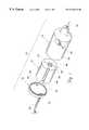
- FIG. 1is an exploded perspective view of a blood pump according to the present invention
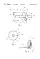
- FIG. 2is a side cross sectional view of a pump element with the motor removed;
- FIG. 3is a cross sectional end view of the pump element taken along line 3 — 3 of FIG. 2;
- FIG. 4is a side view of a cap for the sterile motor housing
- FIG. 5is an exploded side cross sectional view of the pump element according to the present invention with the motor removed;
- FIG. 6is an exploded perspective view of a blood pump with a coaxial blood inlet and blood outlet;
- FIG. 7is an exploded side view of a blood pump with a flexible sleeve
- FIG. 8is an assembled side view of the blood pump with the flexible sleeve of FIG. 7 illustrating the flexible sleeve in an expanded condition
- FIG. 9is a side cross sectional view of an alternative embodiment of a blood pump with a magnetic motor coupling.
- FIG. 10is a side cross sectional view of an alternative embodiment of a blood pump with a mechanical motor coupling.
- FIG. 1A blood pump 10 having a reusable motor stator element 12 , a pump body 14 , and a cap 16 , is illustrated in FIG. 1 .
- the entire blood pump 10is sufficiently small that it may be placed within the surgical field during CPB and other heart surgery.
- the pump body 14 and cap 16together provide a sterile casing for the reusable motor stator element 12 .
- the motor stator element 12when completely encased by the body 14 and cap 16 does not need to be sterile and can be reused.
- the reusable motor stator element 12reduces the overall cost of the blood pump 10 .
- the reusable motor stator element 12reduces the overall cost of the blood pump by allowing the user to reuse the stator element numerous times, thereby reducing the overall per unit cost of the entire blood pump 10 .
- the blood pump 10greatly reduces the priming volume of the system when placed close to the patient thereby reducing the amount of saline and anti-coagulants which are introduced into the patient's blood.
- the pump according to the present inventioncan be used for either beating heart or still heart surgeries.
- the pump body 14includes a blood inflow port 26 arranged axially with respect to the pump impeller 18 and a blood outflow port 28 arranged substantially tangent to an exterior of the pump body 14 .
- the pump body 14has a cylindrical side wall 30 extending from an impeller chamber 32 and configured to surround the reusable motor stator 12 .
- FIG. 2illustrates an impeller 18 arranged in the impeller chamber 32 and non-rotatably connected to a cylindrical magnet 34 positioned within a magnet housing 44 .
- the magnet housing 44hermetically seals the impeller chamber 32 from the motor stator 12 and affords protection against the formation of emboli.
- Bearings 36 , 38rotatable support the cylindrical magnet 34 and impeller 18 .
- the impeller 18is to the cylindrical magnet 34 by a shaft 40 extending through a flexible blood seal 42 .
- the blood seal 42may be constructed of Teflon, silicone, or any other bio-compatible material which prevents blood from the impeller chamber 32 from passing into the magnet housing 44 .
- the cylindrical magnet 34 and bearings 36 , 38are surrounded by and supported in the magnet housing 44 which has a generally cylindrical shape and is configured to be received within a central bore of the reusable motor stator element 12 .
- the impeller 18includes a plurality of vanes arranged to move the blood from the inflow port 26 to the outflow port 28 . As is known in the art, the vanes preferably do not contact the walls of the impeller chamber 32 .
- the reusable motor stator element 12is any one of the known motor elements having a cylindrical central bore 48 for receiving and driving a rotatable cylindrical magnet element such as the cylindrical magnet 34 .
- a suitable motor stator element 12is available as motor # 22an100aa from Koford Engineering, Lisle, Ill.
- the motor stator element 12as shown in FIG. 1, includes two locating recesses 50 , 52 in a top surface 54 thereof.
- the motor stator element 12also includes a longitudinal groove 56 along a cylindrical side surface 58 of the element.
- the locating recesses 50 , 52 and the longitudinal groove 56function to allow the pump body 14 to be received over the motor stator element 12 in only one particular desired orientation.
- the pump body 14preferably includes two locating pins 60 , 62 which correspond to the locating recesses 50 , 52 in the motor stator element 12 .
- the pump body 14also includes an interior key element 64 which is configured to be received in the longitudinal groove 56 in the motor stator element 12 . It should be understood that one or more of the locating features described above may be used with or without the other locating features.
- FIG. 4shows the locking cap 16 which is received over a bottom surface 66 of the motor stator element 12 and provides electrical connections to the motor stator.
- the locking cap 16includes an electrical cable 70 connected to an electrical connector 72 of the cap.
- the cap 16also includes a locking element 76 and an annular sealing member 78 .
- the cap 16snaps onto the pump body 14 when the locking element 76 which is preferably a flexible element snaps into a groove 80 in the interior surface of the pump body cylindrical side wall 30 .
- the annular sealing member 78 of the cap 16is received in a sealing groove 82 in the pump body 14 .
- the pump body 14 and cap 16provide a secure fluid tight hermetic seal to prevent contamination from the non-sterile motor stator element 12 from escaping into the sterile environment in which the blood pump 10 has been placed.
- the motor stator chamberWhen assembled, the motor stator chamber may be evacuated through a port 74 disposed on the cap 16 . Once evacuated, the chamber surrounding the motor stator 12 may be left in a state of negative pressure or carbon dioxide may be introduced into the chamber to equalize the pressure. If the fluid tight seal provided by the magnet housing 44 fails the negative pressure or carbon dioxide in the motor stator chamber prevents air bubbles or emboli from entering the patients blood stream. In fact if any of the seals between the pump body 14 and the motor stator 12 fail because of high suction pressure or some other unforseen accident, air will not enter the patient's blood stream. Instead if there is a vacuum in the motor stator chamber, the motor stator chamber will fill with blood and the leak will stop. If the motor stator chamber is filled with carbon dioxide, blood will readily absorb the carbon dioxide without the danger of a emboli formation.
- the sterile housingmay be formed from two or more members.
- the cylindrical side walls 30may be formed as a part of the pump body 14 , as shown, or as a part of the cap 16 .
- the sterile housingmay be formed around the motor stator element 12 as a one piece molded element.
- the removable motor stator element 12may be removed for reuse.
- the locking cap 16is removed from the pump body 14 and the motor stator element 12 slides out of the pump body.
- the motor stator element 12is preferably reusable, the entire blood pump assembly may also be disposable.
- FIG. 5illustrates one embodiment of a pump body 14 formed from two separate injection molded parts including a main body assembly 86 and a back plate assembly 88 .
- the impeller 18 and cylindrical magnet 34are assembled and inserted into the main body assembly 86 .
- the back plate assembly 88is then inserted into the main body assembly 86 until a flange 90 on the back plate assembly abuts a corresponding flange 92 on the main body assembly.
- the partsmay be secured together with a bio-compatible glue, by ultrasonic welding, or any other known joining technique.
- the locking cap 16may be formed as a single injection molded piece.
- the electrical cable 70 and electrical connector 72may be inserted into the locking cap 16 after molding and secured in place in a known fluid tight manner, such as with a bio-compatible glue.
- the electrical connector 72may be secured within the locking cap 16 during the molding process.
- the electrical connector 72is configured to be received in a corresponding electrical connector of the motor stator element 12 and provides power to the motor and feedback from the motor stator element to a control panel.
- the cable 70may include a plurality of gas lines that can be used to cool the motor stator element. One of the gas lines may be used for delivery of carbon dioxide cooling gas and another of the gas lines would be connected to a vacuum to withdraw heated carbon dioxide.
- FIG. 6illustrates an alternative embodiment of a blood pump 100 including a reusable motor stator element 102 , a pump body 104 , and a cap 106 .
- the pump body 104includes an axial blood inlet 108 and a coaxial blood outlet 110 surrounding the blood inlet.
- a single coaxial blood tubecan be used to deliver blood to and from the patient. This configuration provides space savings and allows the blood tubing to enter the patient through a single incision.
- FIG. 7 and 8illustrate an alternative embodiment of the blood pump 10 of FIG. 1 in which a sterile sleeve 120 is connected to an end of the pump body 14 .
- the sterile sleeve 120is formed of a flexible material such as polypropylene, polyethylene, or the like, and may be connected to the pump body 14 before or after sterilization of the pump body.
- the sterile sleeve 120is initially folded or otherwise compressed longitudinally and secured to the end of the pump body 14 . Once the motor stator element 12 has been inserted into the pump body 14 and the cap 16 has been attached to the pump body, the sterile sleeve 120 is drawn down over the cap and the electrical cable 70 .
- the sterile sleeve 120allows the use of a nonsterile cap 16 and electrical cable 17 and provides a sterile environment.
- the cap 16may be eliminated entirely or permanently connected to the motor stator element 12 .
- the integral cap and motor stator elementwill eliminate the need for the electrical coupling.
- FIG. 9illustrates an alternative embodiment of a blood pump 130 in which the motor stator element 132 is received within a pump body 134 and a magnetic coupling 136 connects an output shaft of the motor stator element with the impeller 138 of the pump body.
- the magnetic coupling 136includes a first magnetic disk 140 connected to the output shaft of the motor stator element 132 and a second magnetic disk 142 secured to a shaft of the impeller 138 .
- the pump body 134is provide with a sealing partition 144 between the first and second magnetic disks 140 , 142 .
- FIG. 10A further alternative embodiment of a blood pump 150 having a mechanical coupling between a motor stator element 152 and an impeller 154 of a pump body 156 is shown in FIG. 10 .
- the mechanical couplingincludes a square shaft 160 connected to the impeller 154 and a corresponding square socket 162 fixed to the output shaft of the motor stator element 152 . It should be understood that the square shaft 160 and corresponding socket 162 may be replaced with any other known mechanical coupling system.
- the blood pump according to the present inventionmay be utilized as an implanted cardiac assist pump by eliminating the electric cable 70 and providing an implantable rechargeable battery within the pump.
- the pumpcontains a rechargeable battery which is arranged in the pump housing so that the battery is adjacent the patient's skin surface. The battery can then be recharged by placing an inductive charger over the battery on the exterior of the patient's skin.
- the blood pumps 10 , 100 , 130 , 150each provide a compact, sterile blood pump which can be placed within the surgical field and even within the chest cavity during heart surgery.
- the blood pump 10may be used during beating heart or still heart surgery and may by used for minimally invasive surgery where the heart is accessed through the ribs or for conventional open chest surgery.
Landscapes
- Health & Medical Sciences (AREA)
- Engineering & Computer Science (AREA)
- Heart & Thoracic Surgery (AREA)
- Mechanical Engineering (AREA)
- Cardiology (AREA)
- Life Sciences & Earth Sciences (AREA)
- Biomedical Technology (AREA)
- Hematology (AREA)
- Anesthesiology (AREA)
- Animal Behavior & Ethology (AREA)
- General Health & Medical Sciences (AREA)
- Public Health (AREA)
- Veterinary Medicine (AREA)
- General Engineering & Computer Science (AREA)
- Power Engineering (AREA)
- External Artificial Organs (AREA)
- Structures Of Non-Positive Displacement Pumps (AREA)
Abstract
Description
Claims (20)
Priority Applications (2)
| Application Number | Priority Date | Filing Date | Title |
|---|---|---|---|
| US09/166,135US6210133B1 (en) | 1998-09-30 | 1998-09-30 | Blood pump with sterile motor housing |
| PCT/US1999/022571WO2000019100A1 (en) | 1998-09-30 | 1999-09-30 | Blood pump with sterile motor housing |
Applications Claiming Priority (1)
| Application Number | Priority Date | Filing Date | Title |
|---|---|---|---|
| US09/166,135US6210133B1 (en) | 1998-09-30 | 1998-09-30 | Blood pump with sterile motor housing |
Publications (1)
| Publication Number | Publication Date |
|---|---|
| US6210133B1true US6210133B1 (en) | 2001-04-03 |
Family
ID=22601967
Family Applications (1)
| Application Number | Title | Priority Date | Filing Date |
|---|---|---|---|
| US09/166,135Expired - Fee RelatedUS6210133B1 (en) | 1998-09-30 | 1998-09-30 | Blood pump with sterile motor housing |
Country Status (2)
| Country | Link |
|---|---|
| US (1) | US6210133B1 (en) |
| WO (1) | WO2000019100A1 (en) |
Cited By (115)
| Publication number | Priority date | Publication date | Assignee | Title |
|---|---|---|---|---|
| WO2001083021A1 (en)* | 2000-04-28 | 2001-11-08 | A-Med Systems, Inc. | Cannulation system and related methods |
| US20030023201A1 (en)* | 2001-04-25 | 2003-01-30 | A-Med Systems, Inc. | Systems and methods for performing minimally invasive cardiac medical procedures |
| US6607362B2 (en)* | 2001-10-11 | 2003-08-19 | Agilent Technologies, Inc. | Micro paddle wheel pump for precise pumping, mixing, dispensing, and valving of blood and reagents |
| US6652493B1 (en)* | 2000-07-05 | 2003-11-25 | Animas Corporation | Infusion pump syringe |
| US6670169B1 (en)* | 1999-09-08 | 2003-12-30 | Levitronix Llc | Bioreactor |
| US6709418B1 (en) | 1997-07-11 | 2004-03-23 | A-Med Systems, Inc. | Apparatus and methods for entering cavities of the body |
| US20040177162A1 (en)* | 2001-06-29 | 2004-09-09 | Wetzel Daniel Thomas | Multi-media jitter removal in an asynchronous digital home network |
| US6790016B2 (en)* | 2002-02-04 | 2004-09-14 | Ching-Yuan Chiang | Motor and its blade unit |
| US6858001B1 (en) | 1997-07-11 | 2005-02-22 | A-Med Systems, Inc. | Single port cardiac support apparatus |
| US20050119599A1 (en)* | 1999-05-18 | 2005-06-02 | A-Med Systems, Inc. | Supplemental port for catheter perfusion of surgical site and methods of use |
| US20050148811A1 (en)* | 1997-07-11 | 2005-07-07 | A-Med Systems, Inc. | Single port cardiac support apparatus |
| US20050154250A1 (en)* | 1998-12-23 | 2005-07-14 | A-Med Systems, Inc. | Left and right side heart support |
| US20050228212A1 (en)* | 1998-05-15 | 2005-10-13 | A-Med Systems, Inc. | Pulmonary and circulatory blood flow support devices and methods for heart surgery procedures |
| US6969379B1 (en) | 1998-08-27 | 2005-11-29 | A-Med Systems, Inc. | Intravascular cannulation apparatus and methods of use |
| US7022100B1 (en) | 1999-09-03 | 2006-04-04 | A-Med Systems, Inc. | Guidable intravascular blood pump and related methods |
| US20070167874A1 (en)* | 2002-04-19 | 2007-07-19 | Dominique Freeman | Method and apparatus for penetrating tissue |
| US20070286754A1 (en)* | 2004-11-26 | 2007-12-13 | Karsten Laing | Circulation pump and method for production of a circulation pump |
| US20090092114A1 (en)* | 2005-08-03 | 2009-04-09 | Kamilo Feher | Wlan and wired mobile communication and location finding system |
| US20110004046A1 (en)* | 2009-07-01 | 2011-01-06 | The Penn State Research Foundation | Blood pump with expandable cannula |
| US7875047B2 (en) | 2002-04-19 | 2011-01-25 | Pelikan Technologies, Inc. | Method and apparatus for a multi-use body fluid sampling device with sterility barrier release |
| US7892183B2 (en) | 2002-04-19 | 2011-02-22 | Pelikan Technologies, Inc. | Method and apparatus for body fluid sampling and analyte sensing |
| US7901365B2 (en) | 2002-04-19 | 2011-03-08 | Pelikan Technologies, Inc. | Method and apparatus for penetrating tissue |
| US7909777B2 (en) | 2002-04-19 | 2011-03-22 | Pelikan Technologies, Inc | Method and apparatus for penetrating tissue |
| US7909774B2 (en) | 2002-04-19 | 2011-03-22 | Pelikan Technologies, Inc. | Method and apparatus for penetrating tissue |
| US7909778B2 (en) | 2002-04-19 | 2011-03-22 | Pelikan Technologies, Inc. | Method and apparatus for penetrating tissue |
| US7909775B2 (en) | 2001-06-12 | 2011-03-22 | Pelikan Technologies, Inc. | Method and apparatus for lancet launching device integrated onto a blood-sampling cartridge |
| US7976476B2 (en) | 2002-04-19 | 2011-07-12 | Pelikan Technologies, Inc. | Device and method for variable speed lancet |
| US7981055B2 (en) | 2001-06-12 | 2011-07-19 | Pelikan Technologies, Inc. | Tissue penetration device |
| US7981056B2 (en) | 2002-04-19 | 2011-07-19 | Pelikan Technologies, Inc. | Methods and apparatus for lancet actuation |
| US7988645B2 (en) | 2001-06-12 | 2011-08-02 | Pelikan Technologies, Inc. | Self optimizing lancing device with adaptation means to temporal variations in cutaneous properties |
| US8007446B2 (en) | 2002-04-19 | 2011-08-30 | Pelikan Technologies, Inc. | Method and apparatus for penetrating tissue |
| US20110236210A1 (en)* | 2004-09-17 | 2011-09-29 | The Penn State Research Foundation | Expandable impeller pump |
| US8062231B2 (en) | 2002-04-19 | 2011-11-22 | Pelikan Technologies, Inc. | Method and apparatus for penetrating tissue |
| US8079960B2 (en) | 2002-04-19 | 2011-12-20 | Pelikan Technologies, Inc. | Methods and apparatus for lancet actuation |
| US8197421B2 (en) | 2002-04-19 | 2012-06-12 | Pelikan Technologies, Inc. | Method and apparatus for penetrating tissue |
| US8221334B2 (en) | 2002-04-19 | 2012-07-17 | Sanofi-Aventis Deutschland Gmbh | Method and apparatus for penetrating tissue |
| US8251921B2 (en) | 2003-06-06 | 2012-08-28 | Sanofi-Aventis Deutschland Gmbh | Method and apparatus for body fluid sampling and analyte sensing |
| US8262614B2 (en) | 2003-05-30 | 2012-09-11 | Pelikan Technologies, Inc. | Method and apparatus for fluid injection |
| US8267870B2 (en) | 2002-04-19 | 2012-09-18 | Sanofi-Aventis Deutschland Gmbh | Method and apparatus for body fluid sampling with hybrid actuation |
| US8282576B2 (en) | 2003-09-29 | 2012-10-09 | Sanofi-Aventis Deutschland Gmbh | Method and apparatus for an improved sample capture device |
| US8296918B2 (en) | 2003-12-31 | 2012-10-30 | Sanofi-Aventis Deutschland Gmbh | Method of manufacturing a fluid sampling device with improved analyte detecting member configuration |
| US8333710B2 (en) | 2002-04-19 | 2012-12-18 | Sanofi-Aventis Deutschland Gmbh | Tissue penetration device |
| US8360992B2 (en) | 2002-04-19 | 2013-01-29 | Sanofi-Aventis Deutschland Gmbh | Method and apparatus for penetrating tissue |
| US8372016B2 (en) | 2002-04-19 | 2013-02-12 | Sanofi-Aventis Deutschland Gmbh | Method and apparatus for body fluid sampling and analyte sensing |
| US8382682B2 (en) | 2002-04-19 | 2013-02-26 | Sanofi-Aventis Deutschland Gmbh | Method and apparatus for penetrating tissue |
| US8435190B2 (en) | 2002-04-19 | 2013-05-07 | Sanofi-Aventis Deutschland Gmbh | Method and apparatus for penetrating tissue |
| US8439872B2 (en) | 1998-03-30 | 2013-05-14 | Sanofi-Aventis Deutschland Gmbh | Apparatus and method for penetration with shaft having a sensor for sensing penetration depth |
| US8449443B2 (en) | 2008-10-06 | 2013-05-28 | Indiana University Research And Technology Corporation | Active or passive assistance in the circulatory system |
| US8485961B2 (en) | 2011-01-05 | 2013-07-16 | Thoratec Corporation | Impeller housing for percutaneous heart pump |
| US8556829B2 (en) | 2002-04-19 | 2013-10-15 | Sanofi-Aventis Deutschland Gmbh | Method and apparatus for penetrating tissue |
| US8574895B2 (en) | 2002-12-30 | 2013-11-05 | Sanofi-Aventis Deutschland Gmbh | Method and apparatus using optical techniques to measure analyte levels |
| US8591393B2 (en) | 2011-01-06 | 2013-11-26 | Thoratec Corporation | Catheter pump |
| US8597170B2 (en) | 2011-01-05 | 2013-12-03 | Thoratec Corporation | Catheter pump |
| US8641644B2 (en) | 2000-11-21 | 2014-02-04 | Sanofi-Aventis Deutschland Gmbh | Blood testing apparatus having a rotatable cartridge with multiple lancing elements and testing means |
| US8652831B2 (en) | 2004-12-30 | 2014-02-18 | Sanofi-Aventis Deutschland Gmbh | Method and apparatus for analyte measurement test time |
| US8668656B2 (en) | 2003-12-31 | 2014-03-11 | Sanofi-Aventis Deutschland Gmbh | Method and apparatus for improving fluidic flow and sample capture |
| US8702624B2 (en) | 2006-09-29 | 2014-04-22 | Sanofi-Aventis Deutschland Gmbh | Analyte measurement device with a single shot actuator |
| US8721517B2 (en) | 2012-05-14 | 2014-05-13 | Thoratec Corporation | Impeller for catheter pump |
| US8721671B2 (en) | 2001-06-12 | 2014-05-13 | Sanofi-Aventis Deutschland Gmbh | Electric lancet actuator |
| US8784335B2 (en) | 2002-04-19 | 2014-07-22 | Sanofi-Aventis Deutschland Gmbh | Body fluid sampling device with a capacitive sensor |
| US8828203B2 (en) | 2004-05-20 | 2014-09-09 | Sanofi-Aventis Deutschland Gmbh | Printable hydrogels for biosensors |
| US8965476B2 (en) | 2010-04-16 | 2015-02-24 | Sanofi-Aventis Deutschland Gmbh | Tissue penetration device |
| WO2015085076A1 (en)* | 2013-12-04 | 2015-06-11 | Heartware, Inc. | Molded vad |
| US9138518B2 (en) | 2011-01-06 | 2015-09-22 | Thoratec Corporation | Percutaneous heart pump |
| US9144401B2 (en) | 2003-06-11 | 2015-09-29 | Sanofi-Aventis Deutschland Gmbh | Low pain penetrating member |
| US20150335803A1 (en)* | 2013-01-07 | 2015-11-26 | National University Corporation Kobe University | Axial flow blood pump |
| US9226699B2 (en) | 2002-04-19 | 2016-01-05 | Sanofi-Aventis Deutschland Gmbh | Body fluid sampling module with a continuous compression tissue interface surface |
| US9248267B2 (en) | 2002-04-19 | 2016-02-02 | Sanofi-Aventis Deustchland Gmbh | Tissue penetration device |
| US9308302B2 (en) | 2013-03-15 | 2016-04-12 | Thoratec Corporation | Catheter pump assembly including a stator |
| US9314194B2 (en) | 2002-04-19 | 2016-04-19 | Sanofi-Aventis Deutschland Gmbh | Tissue penetration device |
| US9327067B2 (en) | 2012-05-14 | 2016-05-03 | Thoratec Corporation | Impeller for catheter pump |
| US9351680B2 (en) | 2003-10-14 | 2016-05-31 | Sanofi-Aventis Deutschland Gmbh | Method and apparatus for a variable user interface |
| US9358329B2 (en) | 2012-07-03 | 2016-06-07 | Thoratec Corporation | Catheter pump |
| US9364593B2 (en) | 2004-09-17 | 2016-06-14 | The Penn State Research Foundation | Heart assist device with expandable impeller pump |
| US9375169B2 (en) | 2009-01-30 | 2016-06-28 | Sanofi-Aventis Deutschland Gmbh | Cam drive for managing disposable penetrating member actions with a single motor and motor and control system |
| US9381288B2 (en) | 2013-03-13 | 2016-07-05 | Thoratec Corporation | Fluid handling system |
| US9386944B2 (en) | 2008-04-11 | 2016-07-12 | Sanofi-Aventis Deutschland Gmbh | Method and apparatus for analyte detecting device |
| US9421311B2 (en) | 2012-07-03 | 2016-08-23 | Thoratec Corporation | Motor assembly for catheter pump |
| US9427532B2 (en) | 2001-06-12 | 2016-08-30 | Sanofi-Aventis Deutschland Gmbh | Tissue penetration device |
| US9446179B2 (en) | 2012-05-14 | 2016-09-20 | Thoratec Corporation | Distal bearing support |
| US9675738B2 (en) | 2015-01-22 | 2017-06-13 | Tc1 Llc | Attachment mechanisms for motor of catheter pump |
| US9675739B2 (en) | 2015-01-22 | 2017-06-13 | Tc1 Llc | Motor assembly with heat exchanger for catheter pump |
| US9770543B2 (en) | 2015-01-22 | 2017-09-26 | Tc1 Llc | Reduced rotational mass motor assembly for catheter pump |
| US9775553B2 (en) | 2004-06-03 | 2017-10-03 | Sanofi-Aventis Deutschland Gmbh | Method and apparatus for a fluid sampling device |
| US9795747B2 (en) | 2010-06-02 | 2017-10-24 | Sanofi-Aventis Deutschland Gmbh | Methods and apparatus for lancet actuation |
| WO2017192919A1 (en)* | 2016-05-04 | 2017-11-09 | Board Of Regents Of The University Of Texas System | Airway suction device |
| US9820684B2 (en) | 2004-06-03 | 2017-11-21 | Sanofi-Aventis Deutschland Gmbh | Method and apparatus for a fluid sampling device |
| US9827356B2 (en) | 2014-04-15 | 2017-11-28 | Tc1 Llc | Catheter pump with access ports |
| US20180010612A1 (en)* | 2016-07-08 | 2018-01-11 | Fenwal, Inc. | Flexible Impeller Pumps And Disposable Fluid Flow Circuits Incorporating Such Pumps |
| US9872947B2 (en) | 2012-05-14 | 2018-01-23 | Tc1 Llc | Sheath system for catheter pump |
| US9907890B2 (en) | 2015-04-16 | 2018-03-06 | Tc1 Llc | Catheter pump with positioning brace |
| US10029037B2 (en) | 2014-04-15 | 2018-07-24 | Tc1 Llc | Sensors for catheter pumps |
| US10105475B2 (en) | 2014-04-15 | 2018-10-23 | Tc1 Llc | Catheter pump introducer systems and methods |
| US10449279B2 (en) | 2014-08-18 | 2019-10-22 | Tc1 Llc | Guide features for percutaneous catheter pump |
| US10520025B1 (en)* | 2012-02-16 | 2019-12-31 | Us Synthetic Corporation | Bearing assembly for use in axial-flow cardiopulmonary bypass blood pumps and related pumps |
| US10525178B2 (en) | 2013-03-15 | 2020-01-07 | Tc1 Llc | Catheter pump assembly including a stator |
| US10583232B2 (en) | 2014-04-15 | 2020-03-10 | Tc1 Llc | Catheter pump with off-set motor position |
| US10722631B2 (en) | 2018-02-01 | 2020-07-28 | Shifamed Holdings, Llc | Intravascular blood pumps and methods of use and manufacture |
| CN111886034A (en)* | 2018-03-23 | 2020-11-03 | 阿比奥梅德欧洲股份有限公司 | method of making a blood pump |
| US11033728B2 (en) | 2013-03-13 | 2021-06-15 | Tc1 Llc | Fluid handling system |
| US11077294B2 (en) | 2013-03-13 | 2021-08-03 | Tc1 Llc | Sheath assembly for catheter pump |
| US11160970B2 (en) | 2016-07-21 | 2021-11-02 | Tc1 Llc | Fluid seals for catheter pump motor assembly |
| US11185677B2 (en) | 2017-06-07 | 2021-11-30 | Shifamed Holdings, Llc | Intravascular fluid movement devices, systems, and methods of use |
| US11219756B2 (en) | 2012-07-03 | 2022-01-11 | Tc1 Llc | Motor assembly for catheter pump |
| US11229786B2 (en) | 2012-05-14 | 2022-01-25 | Tc1 Llc | Impeller for catheter pump |
| US11491322B2 (en)* | 2016-07-21 | 2022-11-08 | Tc1 Llc | Gas-filled chamber for catheter pump motor assembly |
| US11511103B2 (en) | 2017-11-13 | 2022-11-29 | Shifamed Holdings, Llc | Intravascular fluid movement devices, systems, and methods of use |
| US11654275B2 (en) | 2019-07-22 | 2023-05-23 | Shifamed Holdings, Llc | Intravascular blood pumps with struts and methods of use and manufacture |
| US11724089B2 (en) | 2019-09-25 | 2023-08-15 | Shifamed Holdings, Llc | Intravascular blood pump systems and methods of use and control thereof |
| US11964145B2 (en) | 2019-07-12 | 2024-04-23 | Shifamed Holdings, Llc | Intravascular blood pumps and methods of manufacture and use |
| US12102815B2 (en) | 2019-09-25 | 2024-10-01 | Shifamed Holdings, Llc | Catheter blood pumps and collapsible pump housings |
| US12121713B2 (en) | 2019-09-25 | 2024-10-22 | Shifamed Holdings, Llc | Catheter blood pumps and collapsible blood conduits |
| US12161857B2 (en) | 2018-07-31 | 2024-12-10 | Shifamed Holdings, Llc | Intravascular blood pumps and methods of use |
| US12220570B2 (en) | 2018-10-05 | 2025-02-11 | Shifamed Holdings, Llc | Intravascular blood pumps and methods of use |
| US12409310B2 (en) | 2019-12-11 | 2025-09-09 | Shifamed Holdings, Llc | Descending aorta and vena cava blood pumps |
Citations (18)
| Publication number | Priority date | Publication date | Assignee | Title |
|---|---|---|---|---|
| DE378906C (en)* | 1920-08-07 | 1923-08-07 | Eduard Esser & Co | Liquor circulation pump for devices for the wet treatment of textile goods |
| US3048116A (en)* | 1959-04-07 | 1962-08-07 | Basf Ag | Motor pump unit |
| US4135253A (en) | 1976-11-30 | 1979-01-23 | Medtronic, Inc. | Centrifugal blood pump for cardiac assist |
| US4515592A (en) | 1980-05-13 | 1985-05-07 | Arrow International, Inc. | Catheter shield |
| US4625712A (en) | 1983-09-28 | 1986-12-02 | Nimbus, Inc. | High-capacity intravascular blood pump utilizing percutaneous access |
| US4846154A (en) | 1988-06-13 | 1989-07-11 | Macanally Richard B | Dual view endoscope |
| US4895557A (en) | 1987-12-07 | 1990-01-23 | Nimbus Medical, Inc. | Drive mechanism for powering intravascular blood pumps |
| US4898518A (en) | 1988-08-31 | 1990-02-06 | Minnesota Mining & Manufacturing Company | Shaft driven disposable centrifugal pump |
| US4984972A (en) | 1989-10-24 | 1991-01-15 | Minnesota Mining And Manufacturing Co. | Centrifugal blood pump |
| US5118264A (en)* | 1990-01-11 | 1992-06-02 | The Cleveland Clinic Foundation | Purge flow control in rotary blood pumps |
| US5145333A (en)* | 1990-03-01 | 1992-09-08 | The Cleveland Clinic Foundation | Fluid motor driven blood pump |
| US5147186A (en) | 1989-08-04 | 1992-09-15 | Bio Medicus, Inc. | Blood pump drive system |
| WO1994017304A1 (en)* | 1993-01-21 | 1994-08-04 | Nimbus, Inc. | Blood pump with disposable rotor assembly |
| US5539503A (en) | 1994-12-19 | 1996-07-23 | Hewlett-Packard Company | Magnetic drive for a liquid toner cartridge and the liquid supply system for the cartridge |
| US5580216A (en) | 1993-12-22 | 1996-12-03 | Stefan Munsch | Magnetic pump |
| US5741234A (en) | 1996-07-16 | 1998-04-21 | Aboul-Hosn; Walid Nagib | Anatomical cavity access sealing condit |
| US5746709A (en) | 1996-04-25 | 1998-05-05 | Medtronic, Inc. | Intravascular pump and bypass assembly and method for using the same |
| US5785013A (en)* | 1995-12-07 | 1998-07-28 | Pierburg Ag | Electrically driven coolant pump for an internal combustion engine |
Family Cites Families (1)
| Publication number | Priority date | Publication date | Assignee | Title |
|---|---|---|---|---|
| US5393206A (en)* | 1994-06-29 | 1995-02-28 | General Motors Corporation | Fuel pump for a motor vehicle |
- 1998
- 1998-09-30USUS09/166,135patent/US6210133B1/ennot_activeExpired - Fee Related
- 1999
- 1999-09-30WOPCT/US1999/022571patent/WO2000019100A1/enactiveApplication Filing
Patent Citations (19)
| Publication number | Priority date | Publication date | Assignee | Title |
|---|---|---|---|---|
| DE378906C (en)* | 1920-08-07 | 1923-08-07 | Eduard Esser & Co | Liquor circulation pump for devices for the wet treatment of textile goods |
| US3048116A (en)* | 1959-04-07 | 1962-08-07 | Basf Ag | Motor pump unit |
| US4135253A (en) | 1976-11-30 | 1979-01-23 | Medtronic, Inc. | Centrifugal blood pump for cardiac assist |
| US4515592A (en) | 1980-05-13 | 1985-05-07 | Arrow International, Inc. | Catheter shield |
| US4625712A (en) | 1983-09-28 | 1986-12-02 | Nimbus, Inc. | High-capacity intravascular blood pump utilizing percutaneous access |
| US4895557A (en) | 1987-12-07 | 1990-01-23 | Nimbus Medical, Inc. | Drive mechanism for powering intravascular blood pumps |
| US4846154A (en) | 1988-06-13 | 1989-07-11 | Macanally Richard B | Dual view endoscope |
| US4898518A (en) | 1988-08-31 | 1990-02-06 | Minnesota Mining & Manufacturing Company | Shaft driven disposable centrifugal pump |
| US5147186A (en) | 1989-08-04 | 1992-09-15 | Bio Medicus, Inc. | Blood pump drive system |
| US4984972A (en) | 1989-10-24 | 1991-01-15 | Minnesota Mining And Manufacturing Co. | Centrifugal blood pump |
| US5118264A (en)* | 1990-01-11 | 1992-06-02 | The Cleveland Clinic Foundation | Purge flow control in rotary blood pumps |
| US5145333A (en)* | 1990-03-01 | 1992-09-08 | The Cleveland Clinic Foundation | Fluid motor driven blood pump |
| WO1994017304A1 (en)* | 1993-01-21 | 1994-08-04 | Nimbus, Inc. | Blood pump with disposable rotor assembly |
| US5393207A (en)* | 1993-01-21 | 1995-02-28 | Nimbus, Inc. | Blood pump with disposable rotor assembly |
| US5580216A (en) | 1993-12-22 | 1996-12-03 | Stefan Munsch | Magnetic pump |
| US5539503A (en) | 1994-12-19 | 1996-07-23 | Hewlett-Packard Company | Magnetic drive for a liquid toner cartridge and the liquid supply system for the cartridge |
| US5785013A (en)* | 1995-12-07 | 1998-07-28 | Pierburg Ag | Electrically driven coolant pump for an internal combustion engine |
| US5746709A (en) | 1996-04-25 | 1998-05-05 | Medtronic, Inc. | Intravascular pump and bypass assembly and method for using the same |
| US5741234A (en) | 1996-07-16 | 1998-04-21 | Aboul-Hosn; Walid Nagib | Anatomical cavity access sealing condit |
Non-Patent Citations (6)
| Title |
|---|
| Brochure for 3M(TM) Sarns and CDI Health Care Cardiovascular System Products. |
| Brochure for 3M(TM) Sarns(TM) Centrifugal System. |
| Brochure for 3M™ Sarns and CDI Health Care Cardiovascular System Products. |
| Brochure for 3M™ Sarns™ Centrifugal System. |
| Brochure for Patented Cath-Gard(R) shield. |
| Brochure for Patented Cath-Gard® shield. |
Cited By (278)
| Publication number | Priority date | Publication date | Assignee | Title |
|---|---|---|---|---|
| US7090659B2 (en) | 1997-07-11 | 2006-08-15 | A-Med Systems, Inc. | Apparatus and methods for entering cavities of the body |
| US6976996B1 (en) | 1997-07-11 | 2005-12-20 | A-Med Systems, Inc. | Transport pump and organ stabilization apparatus including related methods |
| US20050279370A1 (en)* | 1997-07-11 | 2005-12-22 | A-Med Systems, Inc. | Methods and systems for providing right and/or left heart support during cardiac surgery |
| US6709418B1 (en) | 1997-07-11 | 2004-03-23 | A-Med Systems, Inc. | Apparatus and methods for entering cavities of the body |
| US20040158206A1 (en)* | 1997-07-11 | 2004-08-12 | A-Med Systems, Inc. | Apparatus and methods for entering cavities of the body |
| US7182727B2 (en) | 1997-07-11 | 2007-02-27 | A—Med Systems Inc. | Single port cardiac support apparatus |
| US20050148811A1 (en)* | 1997-07-11 | 2005-07-07 | A-Med Systems, Inc. | Single port cardiac support apparatus |
| US20060100565A1 (en)* | 1997-07-11 | 2006-05-11 | A-Med Systems, Inc. | Transport pump and organ stabilization apparatus including related methods |
| US6858001B1 (en) | 1997-07-11 | 2005-02-22 | A-Med Systems, Inc. | Single port cardiac support apparatus |
| US6974436B1 (en) | 1997-09-19 | 2005-12-13 | A-Med Systems, Inc. | Integrated pump and cannula system and related methods |
| US6935344B1 (en) | 1997-09-19 | 2005-08-30 | A-Med Systems, Inc. | Methods and systems for providing right and/or left heart support during cardiac surgery |
| US20060069299A1 (en)* | 1997-09-19 | 2006-03-30 | A-Med Systems, Inc. | Integrated pump and cannula systems and related methods |
| US8439872B2 (en) | 1998-03-30 | 2013-05-14 | Sanofi-Aventis Deutschland Gmbh | Apparatus and method for penetration with shaft having a sensor for sensing penetration depth |
| US7381179B2 (en) | 1998-05-15 | 2008-06-03 | A-Med Systems, Inc. | Pulmonary and circulatory blood flow support devices and methods for heart surgery procedures |
| US20050228212A1 (en)* | 1998-05-15 | 2005-10-13 | A-Med Systems, Inc. | Pulmonary and circulatory blood flow support devices and methods for heart surgery procedures |
| US20050234288A1 (en)* | 1998-05-15 | 2005-10-20 | A-Med Systems, Inc. | Pulmonary and circulatory blood flow support devices and methods for heart surgery procedures |
| US6969379B1 (en) | 1998-08-27 | 2005-11-29 | A-Med Systems, Inc. | Intravascular cannulation apparatus and methods of use |
| US20050154250A1 (en)* | 1998-12-23 | 2005-07-14 | A-Med Systems, Inc. | Left and right side heart support |
| US6926662B1 (en) | 1998-12-23 | 2005-08-09 | A-Med Systems, Inc. | Left and right side heart support |
| US7785246B2 (en) | 1998-12-23 | 2010-08-31 | Maquet Cardiovascular Llc | Left and right side heart support |
| US8834344B2 (en) | 1998-12-23 | 2014-09-16 | Maquet Cardiovascular Llc | Left and right side heart support |
| US8540615B2 (en) | 1998-12-23 | 2013-09-24 | Maquet Cardiovascular Llc | Left and right side heart support |
| US20050119599A1 (en)* | 1999-05-18 | 2005-06-02 | A-Med Systems, Inc. | Supplemental port for catheter perfusion of surgical site and methods of use |
| US10322218B2 (en) | 1999-09-03 | 2019-06-18 | Maquet Cardiovascular Llc | Guidable intravascular blood pump and related methods |
| US10328191B2 (en) | 1999-09-03 | 2019-06-25 | Maquet Cardiovascular Llc | Guidable intravascular blood pump and related methods |
| US9597437B2 (en) | 1999-09-03 | 2017-03-21 | Maquet Cardiovascular Llc | Guidable intravascular blood pump and related methods |
| US7022100B1 (en) | 1999-09-03 | 2006-04-04 | A-Med Systems, Inc. | Guidable intravascular blood pump and related methods |
| US9789238B2 (en) | 1999-09-03 | 2017-10-17 | Maquet Cardiovascular, Llc | Guidable intravascular blood pump and related methods |
| US20060161095A1 (en)* | 1999-09-03 | 2006-07-20 | A-Med Systems, Inc. | Guidable intravascular blood pump and related methods |
| US10279095B2 (en) | 1999-09-03 | 2019-05-07 | Maquet Cardiovascular Llc | Guidable intravascular blood pump and related methods |
| US10300186B2 (en) | 1999-09-03 | 2019-05-28 | Maquet Cardiovascular Llc | Guidable intravascular blood pump and related methods |
| US10300185B2 (en) | 1999-09-03 | 2019-05-28 | Maquet Cardiovascular Llc | Guidable intravascular blood pump and related methods |
| US10357598B2 (en) | 1999-09-03 | 2019-07-23 | Maquet Cardiovascular Llc | Guidable intravascular blood pump and related methods |
| US10238783B2 (en) | 1999-09-03 | 2019-03-26 | Maquet Cardiovascular Llc | Guidable intravascular blood pump and related methods |
| US9561314B2 (en) | 1999-09-03 | 2017-02-07 | Maquet Cardiovascular Llc | Guidable intravascular blood pump and related methods |
| US7731675B2 (en) | 1999-09-03 | 2010-06-08 | Maquet Cardiovascular Llc | Guidable intravascular blood pump and related methods |
| US20100210895A1 (en)* | 1999-09-03 | 2010-08-19 | Aboul-Hosn Walid N | Guidable Intravascular Blood Pump and Related Methods |
| US8888728B2 (en) | 1999-09-03 | 2014-11-18 | Maquet Cardiovascular Llc | Guidable intravascular blood pump and related methods |
| US9545468B2 (en) | 1999-09-03 | 2017-01-17 | Maquet Cardiovascular Llc | Guidable intravascular blood pump and related methods |
| US9327068B2 (en) | 1999-09-03 | 2016-05-03 | Maquet Cardiovascular Llc | Guidable intravascular blood pump and related methods |
| US6670169B1 (en)* | 1999-09-08 | 2003-12-30 | Levitronix Llc | Bioreactor |
| WO2001083021A1 (en)* | 2000-04-28 | 2001-11-08 | A-Med Systems, Inc. | Cannulation system and related methods |
| US6652493B1 (en)* | 2000-07-05 | 2003-11-25 | Animas Corporation | Infusion pump syringe |
| US8641644B2 (en) | 2000-11-21 | 2014-02-04 | Sanofi-Aventis Deutschland Gmbh | Blood testing apparatus having a rotatable cartridge with multiple lancing elements and testing means |
| US20030023201A1 (en)* | 2001-04-25 | 2003-01-30 | A-Med Systems, Inc. | Systems and methods for performing minimally invasive cardiac medical procedures |
| US6814713B2 (en) | 2001-04-25 | 2004-11-09 | A-Med Systems, Inc. | Systems for performing minimally invasive cardiac medical procedures |
| US20050020968A1 (en)* | 2001-04-25 | 2005-01-27 | A-Med Systems, Inc. | Systems and methods for performing minimally invasive cardiac medical procedures |
| US7981055B2 (en) | 2001-06-12 | 2011-07-19 | Pelikan Technologies, Inc. | Tissue penetration device |
| US9802007B2 (en) | 2001-06-12 | 2017-10-31 | Sanofi-Aventis Deutschland Gmbh | Methods and apparatus for lancet actuation |
| US8282577B2 (en) | 2001-06-12 | 2012-10-09 | Sanofi-Aventis Deutschland Gmbh | Method and apparatus for lancet launching device integrated onto a blood-sampling cartridge |
| US8343075B2 (en) | 2001-06-12 | 2013-01-01 | Sanofi-Aventis Deutschland Gmbh | Tissue penetration device |
| US9694144B2 (en) | 2001-06-12 | 2017-07-04 | Sanofi-Aventis Deutschland Gmbh | Sampling module device and method |
| US8679033B2 (en) | 2001-06-12 | 2014-03-25 | Sanofi-Aventis Deutschland Gmbh | Tissue penetration device |
| US7988645B2 (en) | 2001-06-12 | 2011-08-02 | Pelikan Technologies, Inc. | Self optimizing lancing device with adaptation means to temporal variations in cutaneous properties |
| US7909775B2 (en) | 2001-06-12 | 2011-03-22 | Pelikan Technologies, Inc. | Method and apparatus for lancet launching device integrated onto a blood-sampling cartridge |
| US8016774B2 (en) | 2001-06-12 | 2011-09-13 | Pelikan Technologies, Inc. | Tissue penetration device |
| US8845550B2 (en) | 2001-06-12 | 2014-09-30 | Sanofi-Aventis Deutschland Gmbh | Tissue penetration device |
| US8641643B2 (en) | 2001-06-12 | 2014-02-04 | Sanofi-Aventis Deutschland Gmbh | Sampling module device and method |
| US9427532B2 (en) | 2001-06-12 | 2016-08-30 | Sanofi-Aventis Deutschland Gmbh | Tissue penetration device |
| US8123700B2 (en) | 2001-06-12 | 2012-02-28 | Pelikan Technologies, Inc. | Method and apparatus for lancet launching device integrated onto a blood-sampling cartridge |
| US8622930B2 (en) | 2001-06-12 | 2014-01-07 | Sanofi-Aventis Deutschland Gmbh | Tissue penetration device |
| US8162853B2 (en) | 2001-06-12 | 2012-04-24 | Pelikan Technologies, Inc. | Tissue penetration device |
| US8721671B2 (en) | 2001-06-12 | 2014-05-13 | Sanofi-Aventis Deutschland Gmbh | Electric lancet actuator |
| US8360991B2 (en) | 2001-06-12 | 2013-01-29 | Sanofi-Aventis Deutschland Gmbh | Tissue penetration device |
| US9937298B2 (en) | 2001-06-12 | 2018-04-10 | Sanofi-Aventis Deutschland Gmbh | Tissue penetration device |
| US8206317B2 (en) | 2001-06-12 | 2012-06-26 | Sanofi-Aventis Deutschland Gmbh | Tissue penetration device |
| US8206319B2 (en) | 2001-06-12 | 2012-06-26 | Sanofi-Aventis Deutschland Gmbh | Tissue penetration device |
| US8211037B2 (en) | 2001-06-12 | 2012-07-03 | Pelikan Technologies, Inc. | Tissue penetration device |
| US8216154B2 (en) | 2001-06-12 | 2012-07-10 | Sanofi-Aventis Deutschland Gmbh | Tissue penetration device |
| US8337421B2 (en) | 2001-06-12 | 2012-12-25 | Sanofi-Aventis Deutschland Gmbh | Tissue penetration device |
| US8382683B2 (en) | 2001-06-12 | 2013-02-26 | Sanofi-Aventis Deutschland Gmbh | Tissue penetration device |
| US20040177162A1 (en)* | 2001-06-29 | 2004-09-09 | Wetzel Daniel Thomas | Multi-media jitter removal in an asynchronous digital home network |
| US20040033147A1 (en)* | 2001-10-11 | 2004-02-19 | Paul Lum | Micro paddle wheel pump for precise pumping, mixing, dispensing, and valving of blood and reagents |
| US6607362B2 (en)* | 2001-10-11 | 2003-08-19 | Agilent Technologies, Inc. | Micro paddle wheel pump for precise pumping, mixing, dispensing, and valving of blood and reagents |
| US7011508B2 (en)* | 2001-10-11 | 2006-03-14 | Agilent Technologies, Inc. | Micro paddle wheel pump for precise pumping, mixing, dispensing, and valving of blood and reagents |
| US9560993B2 (en) | 2001-11-21 | 2017-02-07 | Sanofi-Aventis Deutschland Gmbh | Blood testing apparatus having a rotatable cartridge with multiple lancing elements and testing means |
| US6790016B2 (en)* | 2002-02-04 | 2004-09-14 | Ching-Yuan Chiang | Motor and its blade unit |
| US8235915B2 (en) | 2002-04-19 | 2012-08-07 | Sanofi-Aventis Deutschland Gmbh | Method and apparatus for penetrating tissue |
| US8062231B2 (en) | 2002-04-19 | 2011-11-22 | Pelikan Technologies, Inc. | Method and apparatus for penetrating tissue |
| US8337420B2 (en) | 2002-04-19 | 2012-12-25 | Sanofi-Aventis Deutschland Gmbh | Tissue penetration device |
| US8333710B2 (en) | 2002-04-19 | 2012-12-18 | Sanofi-Aventis Deutschland Gmbh | Tissue penetration device |
| US8267870B2 (en) | 2002-04-19 | 2012-09-18 | Sanofi-Aventis Deutschland Gmbh | Method and apparatus for body fluid sampling with hybrid actuation |
| US8360992B2 (en) | 2002-04-19 | 2013-01-29 | Sanofi-Aventis Deutschland Gmbh | Method and apparatus for penetrating tissue |
| US8366637B2 (en) | 2002-04-19 | 2013-02-05 | Sanofi-Aventis Deutschland Gmbh | Method and apparatus for penetrating tissue |
| US8372016B2 (en) | 2002-04-19 | 2013-02-12 | Sanofi-Aventis Deutschland Gmbh | Method and apparatus for body fluid sampling and analyte sensing |
| US9248267B2 (en) | 2002-04-19 | 2016-02-02 | Sanofi-Aventis Deustchland Gmbh | Tissue penetration device |
| US8382682B2 (en) | 2002-04-19 | 2013-02-26 | Sanofi-Aventis Deutschland Gmbh | Method and apparatus for penetrating tissue |
| US8388551B2 (en) | 2002-04-19 | 2013-03-05 | Sanofi-Aventis Deutschland Gmbh | Method and apparatus for multi-use body fluid sampling device with sterility barrier release |
| US8403864B2 (en) | 2002-04-19 | 2013-03-26 | Sanofi-Aventis Deutschland Gmbh | Method and apparatus for penetrating tissue |
| US8414503B2 (en) | 2002-04-19 | 2013-04-09 | Sanofi-Aventis Deutschland Gmbh | Methods and apparatus for lancet actuation |
| US8430828B2 (en) | 2002-04-19 | 2013-04-30 | Sanofi-Aventis Deutschland Gmbh | Method and apparatus for a multi-use body fluid sampling device with sterility barrier release |
| US8435190B2 (en) | 2002-04-19 | 2013-05-07 | Sanofi-Aventis Deutschland Gmbh | Method and apparatus for penetrating tissue |
| US8221334B2 (en) | 2002-04-19 | 2012-07-17 | Sanofi-Aventis Deutschland Gmbh | Method and apparatus for penetrating tissue |
| US8202231B2 (en) | 2002-04-19 | 2012-06-19 | Sanofi-Aventis Deutschland Gmbh | Method and apparatus for penetrating tissue |
| US9907502B2 (en) | 2002-04-19 | 2018-03-06 | Sanofi-Aventis Deutschland Gmbh | Method and apparatus for penetrating tissue |
| US8491500B2 (en) | 2002-04-19 | 2013-07-23 | Sanofi-Aventis Deutschland Gmbh | Methods and apparatus for lancet actuation |
| US8496601B2 (en) | 2002-04-19 | 2013-07-30 | Sanofi-Aventis Deutschland Gmbh | Methods and apparatus for lancet actuation |
| US9839386B2 (en) | 2002-04-19 | 2017-12-12 | Sanofi-Aventis Deustschland Gmbh | Body fluid sampling device with capacitive sensor |
| US8197421B2 (en) | 2002-04-19 | 2012-06-12 | Pelikan Technologies, Inc. | Method and apparatus for penetrating tissue |
| US8556829B2 (en) | 2002-04-19 | 2013-10-15 | Sanofi-Aventis Deutschland Gmbh | Method and apparatus for penetrating tissue |
| US8562545B2 (en) | 2002-04-19 | 2013-10-22 | Sanofi-Aventis Deutschland Gmbh | Tissue penetration device |
| US8574168B2 (en) | 2002-04-19 | 2013-11-05 | Sanofi-Aventis Deutschland Gmbh | Method and apparatus for a multi-use body fluid sampling device with analyte sensing |
| US8579831B2 (en) | 2002-04-19 | 2013-11-12 | Sanofi-Aventis Deutschland Gmbh | Method and apparatus for penetrating tissue |
| US8197423B2 (en) | 2002-04-19 | 2012-06-12 | Pelikan Technologies, Inc. | Method and apparatus for penetrating tissue |
| US9795334B2 (en) | 2002-04-19 | 2017-10-24 | Sanofi-Aventis Deutschland Gmbh | Method and apparatus for penetrating tissue |
| US8157748B2 (en) | 2002-04-19 | 2012-04-17 | Pelikan Technologies, Inc. | Methods and apparatus for lancet actuation |
| US8636673B2 (en) | 2002-04-19 | 2014-01-28 | Sanofi-Aventis Deutschland Gmbh | Tissue penetration device |
| US8079960B2 (en) | 2002-04-19 | 2011-12-20 | Pelikan Technologies, Inc. | Methods and apparatus for lancet actuation |
| US8337419B2 (en) | 2002-04-19 | 2012-12-25 | Sanofi-Aventis Deutschland Gmbh | Tissue penetration device |
| US8007446B2 (en) | 2002-04-19 | 2011-08-30 | Pelikan Technologies, Inc. | Method and apparatus for penetrating tissue |
| US9724021B2 (en) | 2002-04-19 | 2017-08-08 | Sanofi-Aventis Deutschland Gmbh | Method and apparatus for penetrating tissue |
| US7988644B2 (en) | 2002-04-19 | 2011-08-02 | Pelikan Technologies, Inc. | Method and apparatus for a multi-use body fluid sampling device with sterility barrier release |
| US7981056B2 (en) | 2002-04-19 | 2011-07-19 | Pelikan Technologies, Inc. | Methods and apparatus for lancet actuation |
| US8690796B2 (en) | 2002-04-19 | 2014-04-08 | Sanofi-Aventis Deutschland Gmbh | Method and apparatus for penetrating tissue |
| US7976476B2 (en) | 2002-04-19 | 2011-07-12 | Pelikan Technologies, Inc. | Device and method for variable speed lancet |
| US7959582B2 (en) | 2002-04-19 | 2011-06-14 | Pelikan Technologies, Inc. | Method and apparatus for penetrating tissue |
| US7938787B2 (en) | 2002-04-19 | 2011-05-10 | Pelikan Technologies, Inc. | Method and apparatus for penetrating tissue |
| US8784335B2 (en) | 2002-04-19 | 2014-07-22 | Sanofi-Aventis Deutschland Gmbh | Body fluid sampling device with a capacitive sensor |
| US8808201B2 (en) | 2002-04-19 | 2014-08-19 | Sanofi-Aventis Deutschland Gmbh | Methods and apparatus for penetrating tissue |
| US7914465B2 (en) | 2002-04-19 | 2011-03-29 | Pelikan Technologies, Inc. | Method and apparatus for penetrating tissue |
| US7909778B2 (en) | 2002-04-19 | 2011-03-22 | Pelikan Technologies, Inc. | Method and apparatus for penetrating tissue |
| US8845549B2 (en) | 2002-04-19 | 2014-09-30 | Sanofi-Aventis Deutschland Gmbh | Method for penetrating tissue |
| US7909774B2 (en) | 2002-04-19 | 2011-03-22 | Pelikan Technologies, Inc. | Method and apparatus for penetrating tissue |
| US7909777B2 (en) | 2002-04-19 | 2011-03-22 | Pelikan Technologies, Inc | Method and apparatus for penetrating tissue |
| US8905945B2 (en) | 2002-04-19 | 2014-12-09 | Dominique M. Freeman | Method and apparatus for penetrating tissue |
| US7901365B2 (en) | 2002-04-19 | 2011-03-08 | Pelikan Technologies, Inc. | Method and apparatus for penetrating tissue |
| US9498160B2 (en) | 2002-04-19 | 2016-11-22 | Sanofi-Aventis Deutschland Gmbh | Method for penetrating tissue |
| US7892183B2 (en) | 2002-04-19 | 2011-02-22 | Pelikan Technologies, Inc. | Method and apparatus for body fluid sampling and analyte sensing |
| US9339612B2 (en) | 2002-04-19 | 2016-05-17 | Sanofi-Aventis Deutschland Gmbh | Tissue penetration device |
| US9226699B2 (en) | 2002-04-19 | 2016-01-05 | Sanofi-Aventis Deutschland Gmbh | Body fluid sampling module with a continuous compression tissue interface surface |
| US9072842B2 (en) | 2002-04-19 | 2015-07-07 | Sanofi-Aventis Deutschland Gmbh | Method and apparatus for penetrating tissue |
| US9089678B2 (en) | 2002-04-19 | 2015-07-28 | Sanofi-Aventis Deutschland Gmbh | Method and apparatus for penetrating tissue |
| US9089294B2 (en) | 2002-04-19 | 2015-07-28 | Sanofi-Aventis Deutschland Gmbh | Analyte measurement device with a single shot actuator |
| US7875047B2 (en) | 2002-04-19 | 2011-01-25 | Pelikan Technologies, Inc. | Method and apparatus for a multi-use body fluid sampling device with sterility barrier release |
| US20070167874A1 (en)* | 2002-04-19 | 2007-07-19 | Dominique Freeman | Method and apparatus for penetrating tissue |
| US9186468B2 (en) | 2002-04-19 | 2015-11-17 | Sanofi-Aventis Deutschland Gmbh | Method and apparatus for penetrating tissue |
| US9314194B2 (en) | 2002-04-19 | 2016-04-19 | Sanofi-Aventis Deutschland Gmbh | Tissue penetration device |
| US8574895B2 (en) | 2002-12-30 | 2013-11-05 | Sanofi-Aventis Deutschland Gmbh | Method and apparatus using optical techniques to measure analyte levels |
| US9034639B2 (en) | 2002-12-30 | 2015-05-19 | Sanofi-Aventis Deutschland Gmbh | Method and apparatus using optical techniques to measure analyte levels |
| US8262614B2 (en) | 2003-05-30 | 2012-09-11 | Pelikan Technologies, Inc. | Method and apparatus for fluid injection |
| US8251921B2 (en) | 2003-06-06 | 2012-08-28 | Sanofi-Aventis Deutschland Gmbh | Method and apparatus for body fluid sampling and analyte sensing |
| US9144401B2 (en) | 2003-06-11 | 2015-09-29 | Sanofi-Aventis Deutschland Gmbh | Low pain penetrating member |
| US10034628B2 (en) | 2003-06-11 | 2018-07-31 | Sanofi-Aventis Deutschland Gmbh | Low pain penetrating member |
| US8945910B2 (en) | 2003-09-29 | 2015-02-03 | Sanofi-Aventis Deutschland Gmbh | Method and apparatus for an improved sample capture device |
| US8282576B2 (en) | 2003-09-29 | 2012-10-09 | Sanofi-Aventis Deutschland Gmbh | Method and apparatus for an improved sample capture device |
| US9351680B2 (en) | 2003-10-14 | 2016-05-31 | Sanofi-Aventis Deutschland Gmbh | Method and apparatus for a variable user interface |
| US9561000B2 (en) | 2003-12-31 | 2017-02-07 | Sanofi-Aventis Deutschland Gmbh | Method and apparatus for improving fluidic flow and sample capture |
| US8296918B2 (en) | 2003-12-31 | 2012-10-30 | Sanofi-Aventis Deutschland Gmbh | Method of manufacturing a fluid sampling device with improved analyte detecting member configuration |
| US8668656B2 (en) | 2003-12-31 | 2014-03-11 | Sanofi-Aventis Deutschland Gmbh | Method and apparatus for improving fluidic flow and sample capture |
| US8828203B2 (en) | 2004-05-20 | 2014-09-09 | Sanofi-Aventis Deutschland Gmbh | Printable hydrogels for biosensors |
| US9261476B2 (en) | 2004-05-20 | 2016-02-16 | Sanofi Sa | Printable hydrogel for biosensors |
| US9775553B2 (en) | 2004-06-03 | 2017-10-03 | Sanofi-Aventis Deutschland Gmbh | Method and apparatus for a fluid sampling device |
| US9820684B2 (en) | 2004-06-03 | 2017-11-21 | Sanofi-Aventis Deutschland Gmbh | Method and apparatus for a fluid sampling device |
| US11434921B2 (en) | 2004-09-17 | 2022-09-06 | Tc1 Llc | Expandable impeller pump |
| US8376707B2 (en) | 2004-09-17 | 2013-02-19 | Thoratec Corporation | Expandable impeller pump |
| US9364592B2 (en) | 2004-09-17 | 2016-06-14 | The Penn State Research Foundation | Heart assist device with expandable impeller pump |
| US8992163B2 (en) | 2004-09-17 | 2015-03-31 | Thoratec Corporation | Expandable impeller pump |
| US20110236210A1 (en)* | 2004-09-17 | 2011-09-29 | The Penn State Research Foundation | Expandable impeller pump |
| US9717833B2 (en) | 2004-09-17 | 2017-08-01 | The Penn State Research Foundation | Heart assist device with expandable impeller pump |
| US9364593B2 (en) | 2004-09-17 | 2016-06-14 | The Penn State Research Foundation | Heart assist device with expandable impeller pump |
| US11428236B2 (en) | 2004-09-17 | 2022-08-30 | Tc1 Llc | Expandable impeller pump |
| US10215187B2 (en) | 2004-09-17 | 2019-02-26 | Tc1 Llc | Expandable impeller pump |
| US20070286754A1 (en)* | 2004-11-26 | 2007-12-13 | Karsten Laing | Circulation pump and method for production of a circulation pump |
| US8652831B2 (en) | 2004-12-30 | 2014-02-18 | Sanofi-Aventis Deutschland Gmbh | Method and apparatus for analyte measurement test time |
| US20090092114A1 (en)* | 2005-08-03 | 2009-04-09 | Kamilo Feher | Wlan and wired mobile communication and location finding system |
| US10864309B2 (en) | 2006-03-23 | 2020-12-15 | The Penn State Research Foundation | Heart assist device with expandable impeller pump |
| US12404858B2 (en) | 2006-03-23 | 2025-09-02 | The Penn State Research Foundation | Catheter blood pump heart assist device |
| US11708833B2 (en) | 2006-03-23 | 2023-07-25 | The Penn State Research Foundation | Heart assist device with expandable impeller pump |
| US10149932B2 (en) | 2006-03-23 | 2018-12-11 | The Penn State Research Foundation | Heart assist device with expandable impeller pump |
| US8702624B2 (en) | 2006-09-29 | 2014-04-22 | Sanofi-Aventis Deutschland Gmbh | Analyte measurement device with a single shot actuator |
| US9386944B2 (en) | 2008-04-11 | 2016-07-12 | Sanofi-Aventis Deutschland Gmbh | Method and apparatus for analyte detecting device |
| US8449443B2 (en) | 2008-10-06 | 2013-05-28 | Indiana University Research And Technology Corporation | Active or passive assistance in the circulatory system |
| US9375169B2 (en) | 2009-01-30 | 2016-06-28 | Sanofi-Aventis Deutschland Gmbh | Cam drive for managing disposable penetrating member actions with a single motor and motor and control system |
| US8684904B2 (en) | 2009-07-01 | 2014-04-01 | Thoratec Corporation | Blood pump with expandable cannula |
| US20110004046A1 (en)* | 2009-07-01 | 2011-01-06 | The Penn State Research Foundation | Blood pump with expandable cannula |
| US8535211B2 (en) | 2009-07-01 | 2013-09-17 | Thoratec Corporation | Blood pump with expandable cannula |
| US8965476B2 (en) | 2010-04-16 | 2015-02-24 | Sanofi-Aventis Deutschland Gmbh | Tissue penetration device |
| US9795747B2 (en) | 2010-06-02 | 2017-10-24 | Sanofi-Aventis Deutschland Gmbh | Methods and apparatus for lancet actuation |
| US8597170B2 (en) | 2011-01-05 | 2013-12-03 | Thoratec Corporation | Catheter pump |
| US8485961B2 (en) | 2011-01-05 | 2013-07-16 | Thoratec Corporation | Impeller housing for percutaneous heart pump |
| US8591393B2 (en) | 2011-01-06 | 2013-11-26 | Thoratec Corporation | Catheter pump |
| US9138518B2 (en) | 2011-01-06 | 2015-09-22 | Thoratec Corporation | Percutaneous heart pump |
| US10960116B2 (en) | 2011-01-06 | 2021-03-30 | Tci Llc | Percutaneous heart pump |
| US9962475B2 (en) | 2011-01-06 | 2018-05-08 | Tc1 Llc | Percutaneous heart pump |
| US10520025B1 (en)* | 2012-02-16 | 2019-12-31 | Us Synthetic Corporation | Bearing assembly for use in axial-flow cardiopulmonary bypass blood pumps and related pumps |
| US8721517B2 (en) | 2012-05-14 | 2014-05-13 | Thoratec Corporation | Impeller for catheter pump |
| US9675740B2 (en) | 2012-05-14 | 2017-06-13 | Tc1 Llc | Impeller for catheter pump |
| US9872947B2 (en) | 2012-05-14 | 2018-01-23 | Tc1 Llc | Sheath system for catheter pump |
| US11229786B2 (en) | 2012-05-14 | 2022-01-25 | Tc1 Llc | Impeller for catheter pump |
| US11260213B2 (en) | 2012-05-14 | 2022-03-01 | Tc1 Llc | Impeller for catheter pump |
| US11311712B2 (en) | 2012-05-14 | 2022-04-26 | Tc1 Llc | Impeller for catheter pump |
| US10039872B2 (en) | 2012-05-14 | 2018-08-07 | Tc1 Llc | Impeller for catheter pump |
| US11357967B2 (en) | 2012-05-14 | 2022-06-14 | Tc1 Llc | Impeller for catheter pump |
| US10765789B2 (en) | 2012-05-14 | 2020-09-08 | Tc1 Llc | Impeller for catheter pump |
| US9327067B2 (en) | 2012-05-14 | 2016-05-03 | Thoratec Corporation | Impeller for catheter pump |
| US10117980B2 (en) | 2012-05-14 | 2018-11-06 | Tc1 Llc | Distal bearing support |
| US9446179B2 (en) | 2012-05-14 | 2016-09-20 | Thoratec Corporation | Distal bearing support |
| US11944801B2 (en) | 2012-07-03 | 2024-04-02 | Tc1 Llc | Motor assembly for catheter pump |
| US11654276B2 (en) | 2012-07-03 | 2023-05-23 | Tc1 Llc | Catheter pump |
| US12337165B2 (en) | 2012-07-03 | 2025-06-24 | Tc1 Llc | Catheter pump |
| US11925797B2 (en) | 2012-07-03 | 2024-03-12 | Tc1 Llc | Motor assembly for catheter pump |
| US11058865B2 (en) | 2012-07-03 | 2021-07-13 | Tc1 Llc | Catheter pump |
| US11944802B2 (en) | 2012-07-03 | 2024-04-02 | Tc1 Llc | Motor assembly for catheter pump |
| US11219756B2 (en) | 2012-07-03 | 2022-01-11 | Tc1 Llc | Motor assembly for catheter pump |
| US11925796B2 (en) | 2012-07-03 | 2024-03-12 | Tc1 Llc | Motor assembly for catheter pump |
| US9421311B2 (en) | 2012-07-03 | 2016-08-23 | Thoratec Corporation | Motor assembly for catheter pump |
| US10086121B2 (en) | 2012-07-03 | 2018-10-02 | Tc1 Llc | Catheter pump |
| US11833342B2 (en) | 2012-07-03 | 2023-12-05 | Tc1 Llc | Motor assembly for catheter pump |
| US10576193B2 (en) | 2012-07-03 | 2020-03-03 | Tc1 Llc | Motor assembly for catheter pump |
| US9358329B2 (en) | 2012-07-03 | 2016-06-07 | Thoratec Corporation | Catheter pump |
| US11660441B2 (en) | 2012-07-03 | 2023-05-30 | Tc1 Llc | Catheter pump |
| US12102813B2 (en) | 2012-07-03 | 2024-10-01 | Tc1 Llc | Motor assembly for catheter pump |
| US9629947B2 (en)* | 2013-01-07 | 2017-04-25 | National University Corporation Kobe University | Extracorporeal axial flow blood pump with detachable stator |
| US20150335803A1 (en)* | 2013-01-07 | 2015-11-26 | National University Corporation Kobe University | Axial flow blood pump |
| US11850414B2 (en) | 2013-03-13 | 2023-12-26 | Tc1 Llc | Fluid handling system |
| US11547845B2 (en) | 2013-03-13 | 2023-01-10 | Tc1 Llc | Fluid handling system |
| US11964119B2 (en) | 2013-03-13 | 2024-04-23 | Tc1 Llc | Sheath assembly for catheter pump |
| US10632241B2 (en) | 2013-03-13 | 2020-04-28 | Tc1 Llc | Fluid handling system |
| US9381288B2 (en) | 2013-03-13 | 2016-07-05 | Thoratec Corporation | Fluid handling system |
| US11077294B2 (en) | 2013-03-13 | 2021-08-03 | Tc1 Llc | Sheath assembly for catheter pump |
| US11033728B2 (en) | 2013-03-13 | 2021-06-15 | Tc1 Llc | Fluid handling system |
| US10525178B2 (en) | 2013-03-15 | 2020-01-07 | Tc1 Llc | Catheter pump assembly including a stator |
| US9308302B2 (en) | 2013-03-15 | 2016-04-12 | Thoratec Corporation | Catheter pump assembly including a stator |
| US10071192B2 (en) | 2013-03-15 | 2018-09-11 | Tc1 Llp | Catheter pump assembly including a stator |
| US10786610B2 (en) | 2013-03-15 | 2020-09-29 | Tc1 Llc | Catheter pump assembly including a stator |
| US9616158B2 (en) | 2013-12-04 | 2017-04-11 | Heartware, Inc. | Molded VAD |
| WO2015085076A1 (en)* | 2013-12-04 | 2015-06-11 | Heartware, Inc. | Molded vad |
| US10576192B2 (en) | 2014-04-15 | 2020-03-03 | Tc1 Llc | Catheter pump with access ports |
| US10709829B2 (en) | 2014-04-15 | 2020-07-14 | Tc1 Llc | Catheter pump introducer systems and methods |
| US11173297B2 (en) | 2014-04-15 | 2021-11-16 | Tc1 Llc | Catheter pump with off-set motor position |
| US12059559B2 (en) | 2014-04-15 | 2024-08-13 | Tc1 Llc | Sensors for catheter pumps |
| US9827356B2 (en) | 2014-04-15 | 2017-11-28 | Tc1 Llc | Catheter pump with access ports |
| US10029037B2 (en) | 2014-04-15 | 2018-07-24 | Tc1 Llc | Sensors for catheter pumps |
| US10864308B2 (en) | 2014-04-15 | 2020-12-15 | Tc1 Llc | Sensors for catheter pumps |
| US10105475B2 (en) | 2014-04-15 | 2018-10-23 | Tc1 Llc | Catheter pump introducer systems and methods |
| US11331470B2 (en) | 2014-04-15 | 2022-05-17 | Tc1 Llc | Catheter pump with access ports |
| US11786720B2 (en) | 2014-04-15 | 2023-10-17 | Tc1 Llc | Catheter pump with off-set motor position |
| US10583232B2 (en) | 2014-04-15 | 2020-03-10 | Tc1 Llc | Catheter pump with off-set motor position |
| US10449279B2 (en) | 2014-08-18 | 2019-10-22 | Tc1 Llc | Guide features for percutaneous catheter pump |
| US12053598B2 (en) | 2015-01-22 | 2024-08-06 | Tc1 Llc | Reduced rotational mass motor assembly for catheter pump |
| US9770543B2 (en) | 2015-01-22 | 2017-09-26 | Tc1 Llc | Reduced rotational mass motor assembly for catheter pump |
| US11998729B2 (en) | 2015-01-22 | 2024-06-04 | Tc1 Llc | Motor assembly with heat exchanger for catheter pump |
| US11497896B2 (en) | 2015-01-22 | 2022-11-15 | Tc1 Llc | Reduced rotational mass motor assembly for catheter pump |
| US11633586B2 (en) | 2015-01-22 | 2023-04-25 | Tc1 Llc | Motor assembly with heat exchanger for catheter pump |
| US9675738B2 (en) | 2015-01-22 | 2017-06-13 | Tc1 Llc | Attachment mechanisms for motor of catheter pump |
| US10709830B2 (en) | 2015-01-22 | 2020-07-14 | Tc1 Llc | Reduced rotational mass motor assembly for catheter pump |
| US11911579B2 (en) | 2015-01-22 | 2024-02-27 | Tc1 Llc | Reduced rotational mass motor assembly for catheter pump |
| US10737005B2 (en) | 2015-01-22 | 2020-08-11 | Tc1 Llc | Motor assembly with heat exchanger for catheter pump |
| US9987404B2 (en) | 2015-01-22 | 2018-06-05 | Tc1 Llc | Motor assembly with heat exchanger for catheter pump |
| US9675739B2 (en) | 2015-01-22 | 2017-06-13 | Tc1 Llc | Motor assembly with heat exchanger for catheter pump |
| US11759612B2 (en) | 2015-01-22 | 2023-09-19 | Tc1 Llc | Reduced rotational mass motor assembly for catheter pump |
| US9907890B2 (en) | 2015-04-16 | 2018-03-06 | Tc1 Llc | Catheter pump with positioning brace |
| US11260162B2 (en)* | 2016-05-04 | 2022-03-01 | Board Of Regents, The University Of Texas System | Airway suction device |
| WO2017192919A1 (en)* | 2016-05-04 | 2017-11-09 | Board Of Regents Of The University Of Texas System | Airway suction device |
| US20180010612A1 (en)* | 2016-07-08 | 2018-01-11 | Fenwal, Inc. | Flexible Impeller Pumps And Disposable Fluid Flow Circuits Incorporating Such Pumps |
| US10865805B2 (en)* | 2016-07-08 | 2020-12-15 | Fenwal, Inc. | Flexible impeller pumps and disposable fluid flow circuits incorporating such pumps |
| US12350483B2 (en) | 2016-07-21 | 2025-07-08 | Tc1 Llc | Fluid seals for catheter pump motor assembly |
| US11918800B2 (en) | 2016-07-21 | 2024-03-05 | Tc1 Llc | Gas-filled chamber for catheter pump motor assembly |
| US11925795B2 (en) | 2016-07-21 | 2024-03-12 | Tc1 Llc | Fluid seals for catheter pump motor assembly |
| US12168120B2 (en) | 2016-07-21 | 2024-12-17 | Tc1 Llc | Gas-filled chamber for catheter pump motor assembly |
| US11160970B2 (en) | 2016-07-21 | 2021-11-02 | Tc1 Llc | Fluid seals for catheter pump motor assembly |
| US11491322B2 (en)* | 2016-07-21 | 2022-11-08 | Tc1 Llc | Gas-filled chamber for catheter pump motor assembly |
| US12011582B2 (en) | 2016-07-21 | 2024-06-18 | Tc1 Llc | Fluid seals for catheter pump motor assembly |
| US11717670B2 (en) | 2017-06-07 | 2023-08-08 | Shifamed Holdings, LLP | Intravascular fluid movement devices, systems, and methods of use |
| US11185677B2 (en) | 2017-06-07 | 2021-11-30 | Shifamed Holdings, Llc | Intravascular fluid movement devices, systems, and methods of use |
| US11511103B2 (en) | 2017-11-13 | 2022-11-29 | Shifamed Holdings, Llc | Intravascular fluid movement devices, systems, and methods of use |
| US12076545B2 (en) | 2018-02-01 | 2024-09-03 | Shifamed Holdings, Llc | Intravascular blood pumps and methods of use and manufacture |
| US11229784B2 (en) | 2018-02-01 | 2022-01-25 | Shifamed Holdings, Llc | Intravascular blood pumps and methods of use and manufacture |
| US10722631B2 (en) | 2018-02-01 | 2020-07-28 | Shifamed Holdings, Llc | Intravascular blood pumps and methods of use and manufacture |
| CN111886034A (en)* | 2018-03-23 | 2020-11-03 | 阿比奥梅德欧洲股份有限公司 | method of making a blood pump |
| US12161857B2 (en) | 2018-07-31 | 2024-12-10 | Shifamed Holdings, Llc | Intravascular blood pumps and methods of use |
| US12220570B2 (en) | 2018-10-05 | 2025-02-11 | Shifamed Holdings, Llc | Intravascular blood pumps and methods of use |
| US11964145B2 (en) | 2019-07-12 | 2024-04-23 | Shifamed Holdings, Llc | Intravascular blood pumps and methods of manufacture and use |
| US11654275B2 (en) | 2019-07-22 | 2023-05-23 | Shifamed Holdings, Llc | Intravascular blood pumps with struts and methods of use and manufacture |
| US12102815B2 (en) | 2019-09-25 | 2024-10-01 | Shifamed Holdings, Llc | Catheter blood pumps and collapsible pump housings |
| US12121713B2 (en) | 2019-09-25 | 2024-10-22 | Shifamed Holdings, Llc | Catheter blood pumps and collapsible blood conduits |
| US11724089B2 (en) | 2019-09-25 | 2023-08-15 | Shifamed Holdings, Llc | Intravascular blood pump systems and methods of use and control thereof |
| US12409310B2 (en) | 2019-12-11 | 2025-09-09 | Shifamed Holdings, Llc | Descending aorta and vena cava blood pumps |
Also Published As
| Publication number | Publication date |
|---|---|
| WO2000019100A1 (en) | 2000-04-06 |
Similar Documents
| Publication | Publication Date | Title |
|---|---|---|
| US6210133B1 (en) | Blood pump with sterile motor housing | |
| US9044535B2 (en) | Extracorporeal blood pump with disposable pump head portion having magnetically levitated impeller | |
| US6152704A (en) | Blood pump with turbine drive | |
| WO2000019097A1 (en) | Blood pump system with magnetic cable drive | |
| EP3077018B1 (en) | Molded vad | |
| US6176848B1 (en) | Intravascular blood pump | |
| US9616157B2 (en) | Blood pump | |
| US5964694A (en) | Method and apparatus for cardiac blood flow assistance | |
| US5376114A (en) | Cannula pumps for temporary cardiac support and methods of their application and use | |
| CN107412892B (en) | Catheter sheath and ventricular assist circulation device | |
| US6723039B2 (en) | Methods, systems and devices relating to implantable fluid pumps | |
| CN107080871B (en) | Catheter sheath and ventricular assist circulation device | |
| US6018208A (en) | Articulated motor stator assembly for a pump | |
| US5921913A (en) | Statorless intravascular microaxial flow pump | |
| US8002691B2 (en) | Fluid pressure generating means | |
| US20030208097A1 (en) | Cannulation system and related methods | |
| EP2263712B1 (en) | Fluid pumping device and static sealing components | |
| CN107080870A (en) | Blood pump and making assisted circulation of ventriculus cordis device | |
| US20070161847A1 (en) | Staged implantation of ventricular assist devices | |
| WO2014116639A1 (en) | Sterilizable cable system for implantable blood pump | |
| WO2011069109A2 (en) | Total artificial heart | |
| WO1992003181A1 (en) | Cardiac assist centrifugal pump | |
| EP1263495B1 (en) | Cannulation system | |
| WO2001083021A1 (en) | Cannulation system and related methods | |
| Chung | Dynamic Characterisation of the Impeller-Bearing-Pump Housing System of a Rotary Blood Pump Via Experiment |
Legal Events
| Date | Code | Title | Description |
|---|---|---|---|
| AS | Assignment | Owner name:A-MED SYSTEMS, INC., CALIFORNIA Free format text:ASSIGNMENT OF ASSIGNORS INTEREST;ASSIGNORS:ABOUL-HOSN, WALID NAJIB;NOOR, SEDIG;KANZ, WILLIAM RUSSELL;AND OTHERS;REEL/FRAME:009725/0576;SIGNING DATES FROM 19981212 TO 19990110 | |
| FPAY | Fee payment | Year of fee payment:4 | |
| AS | Assignment | Owner name:GUIDANT CORPORATION, MINNESOTA Free format text:ASSIGNMENT OF ASSIGNORS INTEREST;ASSIGNOR:A-MED SYSTEMS, INC.;REEL/FRAME:016274/0961 Effective date:20050708 | |
| FEPP | Fee payment procedure | Free format text:PAYOR NUMBER ASSIGNED (ORIGINAL EVENT CODE: ASPN); ENTITY STATUS OF PATENT OWNER: LARGE ENTITY | |
| FEPP | Fee payment procedure | Free format text:PAYER NUMBER DE-ASSIGNED (ORIGINAL EVENT CODE: RMPN); ENTITY STATUS OF PATENT OWNER: LARGE ENTITY Free format text:PAYOR NUMBER ASSIGNED (ORIGINAL EVENT CODE: ASPN); ENTITY STATUS OF PATENT OWNER: LARGE ENTITY | |
| FEPP | Fee payment procedure | Free format text:PAT HOLDER NO LONGER CLAIMS SMALL ENTITY STATUS, ENTITY STATUS SET TO UNDISCOUNTED (ORIGINAL EVENT CODE: STOL); ENTITY STATUS OF PATENT OWNER: LARGE ENTITY | |
| REFU | Refund | Free format text:REFUND - PAYMENT OF MAINTENANCE FEE, 8TH YR, SMALL ENTITY (ORIGINAL EVENT CODE: R2552); ENTITY STATUS OF PATENT OWNER: LARGE ENTITY | |
| AS | Assignment | Owner name:MAQUET CARDIOVASCULAR, LLC, A DELAWARE CORPORATION Free format text:ASSIGNMENT OF ASSIGNORS INTEREST;ASSIGNOR:GUIDANT CORPORATION, AN INDIANA CORPORATION;REEL/FRAME:020986/0839 Effective date:20080102 | |
| FPAY | Fee payment | Year of fee payment:8 | |
| SULP | Surcharge for late payment | Year of fee payment:7 | |
| REMI | Maintenance fee reminder mailed | ||
| LAPS | Lapse for failure to pay maintenance fees | ||
| STCH | Information on status: patent discontinuation | Free format text:PATENT EXPIRED DUE TO NONPAYMENT OF MAINTENANCE FEES UNDER 37 CFR 1.362 | |
| FP | Lapsed due to failure to pay maintenance fee | Effective date:20130403 |