US6209540B1 - Artificial respiration apparatus - Google Patents
Artificial respiration apparatusDownload PDFInfo
- Publication number
- US6209540B1 US6209540B1US09/280,973US28097399AUS6209540B1US 6209540 B1US6209540 B1US 6209540B1US 28097399 AUS28097399 AUS 28097399AUS 6209540 B1US6209540 B1US 6209540B1
- Authority
- US
- United States
- Prior art keywords
- pressure
- diaphragm
- positive
- blower
- negative
- Prior art date
- Legal status (The legal status is an assumption and is not a legal conclusion. Google has not performed a legal analysis and makes no representation as to the accuracy of the status listed.)
- Expired - Lifetime
Links
Images


Classifications
- A—HUMAN NECESSITIES
- A61—MEDICAL OR VETERINARY SCIENCE; HYGIENE
- A61M—DEVICES FOR INTRODUCING MEDIA INTO, OR ONTO, THE BODY; DEVICES FOR TRANSDUCING BODY MEDIA OR FOR TAKING MEDIA FROM THE BODY; DEVICES FOR PRODUCING OR ENDING SLEEP OR STUPOR
- A61M16/00—Devices for influencing the respiratory system of patients by gas treatment, e.g. ventilators; Tracheal tubes
- A61M16/20—Valves specially adapted to medical respiratory devices
- A61M16/201—Controlled valves
- A61M16/202—Controlled valves electrically actuated
- A—HUMAN NECESSITIES
- A61—MEDICAL OR VETERINARY SCIENCE; HYGIENE
- A61M—DEVICES FOR INTRODUCING MEDIA INTO, OR ONTO, THE BODY; DEVICES FOR TRANSDUCING BODY MEDIA OR FOR TAKING MEDIA FROM THE BODY; DEVICES FOR PRODUCING OR ENDING SLEEP OR STUPOR
- A61M16/00—Devices for influencing the respiratory system of patients by gas treatment, e.g. ventilators; Tracheal tubes
- A61M16/0003—Accessories therefor, e.g. sensors, vibrators, negative pressure
- A61M16/0006—Accessories therefor, e.g. sensors, vibrators, negative pressure with means for creating vibrations in patients' airways
- A—HUMAN NECESSITIES
- A61—MEDICAL OR VETERINARY SCIENCE; HYGIENE
- A61M—DEVICES FOR INTRODUCING MEDIA INTO, OR ONTO, THE BODY; DEVICES FOR TRANSDUCING BODY MEDIA OR FOR TAKING MEDIA FROM THE BODY; DEVICES FOR PRODUCING OR ENDING SLEEP OR STUPOR
- A61M16/00—Devices for influencing the respiratory system of patients by gas treatment, e.g. ventilators; Tracheal tubes
- A61M16/0003—Accessories therefor, e.g. sensors, vibrators, negative pressure
- A61M16/0009—Accessories therefor, e.g. sensors, vibrators, negative pressure with sub-atmospheric pressure, e.g. during expiration
- A—HUMAN NECESSITIES
- A61—MEDICAL OR VETERINARY SCIENCE; HYGIENE
- A61M—DEVICES FOR INTRODUCING MEDIA INTO, OR ONTO, THE BODY; DEVICES FOR TRANSDUCING BODY MEDIA OR FOR TAKING MEDIA FROM THE BODY; DEVICES FOR PRODUCING OR ENDING SLEEP OR STUPOR
- A61M16/00—Devices for influencing the respiratory system of patients by gas treatment, e.g. ventilators; Tracheal tubes
- A61M16/0057—Pumps therefor
- A61M16/0081—Bag or bellow in a bottle
- A—HUMAN NECESSITIES
- A61—MEDICAL OR VETERINARY SCIENCE; HYGIENE
- A61M—DEVICES FOR INTRODUCING MEDIA INTO, OR ONTO, THE BODY; DEVICES FOR TRANSDUCING BODY MEDIA OR FOR TAKING MEDIA FROM THE BODY; DEVICES FOR PRODUCING OR ENDING SLEEP OR STUPOR
- A61M16/00—Devices for influencing the respiratory system of patients by gas treatment, e.g. ventilators; Tracheal tubes
- A61M16/021—Devices for influencing the respiratory system of patients by gas treatment, e.g. ventilators; Tracheal tubes operated by electrical means
- A61M16/022—Control means therefor
- A61M16/024—Control means therefor including calculation means, e.g. using a processor
- A—HUMAN NECESSITIES
- A61—MEDICAL OR VETERINARY SCIENCE; HYGIENE
- A61M—DEVICES FOR INTRODUCING MEDIA INTO, OR ONTO, THE BODY; DEVICES FOR TRANSDUCING BODY MEDIA OR FOR TAKING MEDIA FROM THE BODY; DEVICES FOR PRODUCING OR ENDING SLEEP OR STUPOR
- A61M16/00—Devices for influencing the respiratory system of patients by gas treatment, e.g. ventilators; Tracheal tubes
- A61M16/0057—Pumps therefor
- A61M16/0066—Blowers or centrifugal pumps
- A—HUMAN NECESSITIES
- A61—MEDICAL OR VETERINARY SCIENCE; HYGIENE
- A61M—DEVICES FOR INTRODUCING MEDIA INTO, OR ONTO, THE BODY; DEVICES FOR TRANSDUCING BODY MEDIA OR FOR TAKING MEDIA FROM THE BODY; DEVICES FOR PRODUCING OR ENDING SLEEP OR STUPOR
- A61M16/00—Devices for influencing the respiratory system of patients by gas treatment, e.g. ventilators; Tracheal tubes
- A61M16/08—Bellows; Connecting tubes ; Water traps; Patient circuits
- A61M16/0816—Joints or connectors
- A61M16/0841—Joints or connectors for sampling
- A61M16/0858—Pressure sampling ports
- A—HUMAN NECESSITIES
- A61—MEDICAL OR VETERINARY SCIENCE; HYGIENE
- A61M—DEVICES FOR INTRODUCING MEDIA INTO, OR ONTO, THE BODY; DEVICES FOR TRANSDUCING BODY MEDIA OR FOR TAKING MEDIA FROM THE BODY; DEVICES FOR PRODUCING OR ENDING SLEEP OR STUPOR
- A61M16/00—Devices for influencing the respiratory system of patients by gas treatment, e.g. ventilators; Tracheal tubes
- A61M16/10—Preparation of respiratory gases or vapours
- A61M16/105—Filters
- A61M16/106—Filters in a path
- A61M16/107—Filters in a path in the inspiratory path
- A—HUMAN NECESSITIES
- A61—MEDICAL OR VETERINARY SCIENCE; HYGIENE
- A61M—DEVICES FOR INTRODUCING MEDIA INTO, OR ONTO, THE BODY; DEVICES FOR TRANSDUCING BODY MEDIA OR FOR TAKING MEDIA FROM THE BODY; DEVICES FOR PRODUCING OR ENDING SLEEP OR STUPOR
- A61M16/00—Devices for influencing the respiratory system of patients by gas treatment, e.g. ventilators; Tracheal tubes
- A61M16/0003—Accessories therefor, e.g. sensors, vibrators, negative pressure
- A61M2016/0015—Accessories therefor, e.g. sensors, vibrators, negative pressure inhalation detectors
- A61M2016/0018—Accessories therefor, e.g. sensors, vibrators, negative pressure inhalation detectors electrical
- A61M2016/0021—Accessories therefor, e.g. sensors, vibrators, negative pressure inhalation detectors electrical with a proportional output signal, e.g. from a thermistor
- A—HUMAN NECESSITIES
- A61—MEDICAL OR VETERINARY SCIENCE; HYGIENE
- A61M—DEVICES FOR INTRODUCING MEDIA INTO, OR ONTO, THE BODY; DEVICES FOR TRANSDUCING BODY MEDIA OR FOR TAKING MEDIA FROM THE BODY; DEVICES FOR PRODUCING OR ENDING SLEEP OR STUPOR
- A61M2205/00—General characteristics of the apparatus
- A61M2205/42—Reducing noise
Definitions
- the conventional respiration apparatus 50includes: a blower 52 for simultaneously generating a positive pressure Ap and a negative pressure An; a rotary valve mechanism 54 for alternately selecting the positive pressure Ap and the negative pressure An generated by the blower 52 and converting the positive and negative pressures into an oscillating air pressure Apn; and a diaphragm block 56 which is urged by the oscillating air pressure Apn from the rotary valve mechanism 54 , so as to supply air to a patient P.
- the artificial respiration apparatus 50includes: a diaphragm neutral position controller 60 for maintaining a neutral position of a diaphragm 561 of the diaphragm block 56 ; and a respiration gas port 62 for introducing the respiration gas.
- the blower 52has a positive pressure pipe 521 and a negative pressure pipe 522 , so that air is supplied to the blower 52 through the negative pressure pipe 522 and discharges the air through the positive pressure pipe 521 .
- the negative pressure pipe 522is connected to an orifice pipe 523 communicating with the open air.
- the positive pressure pipe 521is connected to an orifice pipe 524 communicating with the open air.
- the rotary valve mechanism 54is constituted by a rotary valve 544 having ports 541 , 542 , 543 , and a drive block 545 for rotating the rotary valve 544 .
- the drive block 545includes a motor and a reduction gear (not depicted) so as to rotate the rotary valve 544 at 900 rpm for example. While the rotary valve 544 makes a single turn, the port 541 and the port 542 are successively made to communicate with the port 543 .
- the port 543is connected to an oscillating air pressure pipe 546 for transmitting the oscillating air pressure Apn to the diaphragm block 56 .
- a flow control valve 547is inserted into the oscillating air pressure pipe 546 .
- the respiration gas port 62is constituted by a blender 621 for mixing the open air with oxygen prepared in advance; and a humidifier 622 for humidifying the gas to be sent out from the blender 521 .
- the humidifier 622is connected to a respiration gas pipe 623 for supplying to the patient P the respiration gas Ai which has passed through the humidifier.
- the respiration gas pipe 623communicates with the pressurized chamber 563 and has a pressure sensor 624 provided in the vicinity of the patient P.
- the rotary valve mechanism 54makes the discharge side of the blower 52 closed and the suction side of the blower 52 communicate with the oscillating air pressure pipe 546 .
- the discharge sideis also connected to an orifice pipe 524 communicating with the open air.
- the inventors of the present inventionhave found that the aforementioned object can be achieved by replacing the blower generating both of a positive pressure and a negative pressure by a positive pressure blower for generating only a positive pressure in combination with a negative pressure blower for generating only a negative pressure.
- Thiscan significantly reduce the load (i.e., power consumption), which in turn realizes a smaller size and weight as well as a lower cost.
- a large-size blower of a special typeordinary two blowers are used.
- Such an ordinary bloweris small in size and weight and is available on market, and can be used with a 100V commercial power source.
- the artificial respiration apparatuscomprises: a positive pressure generator for generating a positive air pressure; a negative pressure generator for generating a negative air pressure; an oscillating air pressure generation mechanism for alternately selecting the positive pressure generated by the positive pressure generator and the negative pressure generated by the negative pressure generator so as to convert the positive pressure and the negative pressure into an oscillating air pressure; and a diaphragm block urged by the oscillating air pressure from the oscillating air pressure generation mechanism, so as to supply a gas into a mouth of a patient.
- the artificial respiration apparatusincludes: a negative pressure blower (negative pressure generator) which sucks air at its suction side and discharging the sucked air into the open air, thus generating a negative pressure; and a positive pressure blower (positive pressure generator) which sucks air from the open air and discharges the sucked air to its discharge side, thus generating a positive pressure.
- a negative pressure blowernegative pressure generator
- a positive pressure blowerpositive pressure generator
- a rotary valve mechanismoscillating air pressure generation mechanism
- the discharge side of the positive pressure blowercommunicates with an oscillating air pressure pipe and the suction side of the negative blower closed.
- the positive pressure blowercan suck air from the open air. Accordingly, the orifice pipe used at the suction side in the conventional respirator is not required.
- the rotary valve mechanism(oscillating air pressure generation mechanism) makes the discharge side of the positive pressure blower closed and the suction side of the negative pressure blower communicate with the oscillating air pressure pipe.
- the negative pressure blowercan discharge air into the open air. Accordingly, the orifice pipe used at the discharge side in the conventional respirator is not required.
- the artificial respiration apparatusin the artificial respiration apparatus according to the present invention, there is no useless air leak out or flow in. This can significantly reduce the blower load.
- the conventional respiratorrequires a single blower of 1.35 KW, whereas the present invention requires only 0.85 KW for use of two blowers in combination.
- the power consumptionis reduced by about 37%.
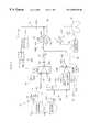
- FIG. 1shows a configuration of an artificial respiration apparatus according to an embodiment of the present invention.
- FIG. 2is a graph showing as an example, discharge characteristic of a positive pressure blower and suction characteristic of a negative pressure blower in the artificial respiration apparatus shown in FIG. 1 .
- FIG. 3is a cross sectional view of a pressure regulating valve used in a diaphragm neutral position controller of FIG. 1 in a state for selecting a positive pressure releasing passage and a negative pressure application passage.
- FIG. 4is a cross sectional view of the pressure regulating valve used in the diaphragm neutral position controller of FIG. 1 in a state for selecting a negative pressure releasing passage and a positive pressure application passage.
- FIG. 5shows a configuration of a conventional artificial respiration apparatus.
- FIG. 1shows a configuration of an artificial respiration apparatus according to an embodiment of the present invention.
- FIG. 2is a graph showing as an example, discharge characteristic of a positive pressure blower and suction characteristic of a negative pressure blower in the artificial respiration apparatus shown in FIG. 1 .
- FIG. 1 and FIG. 2show like components as in FIG. 5 .
- the artificial respiration apparatus 10includes: a positive blower 12 p (positive pressure generator) for generating a positive pressure Ap; a negative blower 12 n (negative pressure generator) for generating a negative pressure An; a rotary valve mechanism 54 (oscillating air pressure generation mechanism) alternately selecting the positive pressure Ap generated by the positive blower 12 p and the negative pressure An generated by the negative blower 12 n; and a diaphragm block 56 urged by the oscillating air pressure Apn from the rotary valve mechanism 54 so as to supply air to the patient P.
- a positive blower 12 ppositive pressure generator
- a negative blower 12 nnegative pressure generator
- a rotary valve mechanism 54oscilscillating air pressure generation mechanism
- the positive blower 12 psucks air via a filter 14 from the atmosphere and discharges the sucked air to a positive pressure pipe 521 to generate a positive pressure Ap.
- the filter 14serves to remove dusts from the air to be sucked.
- the negative blower 12 nsucks air from the negative pressure pipe 522 and discharges the sucked air via a silencer 16 into the atmosphere, thus generating the negative pressure An.
- the silencer 16serves to reduce the sound caused by air discharge.
- flow control valves 181 and 182are provided at the suction side of the positive blower 12 p and the discharge side of the negative blower 12 n, respectively.
- the discharge characteristic of the positive blower 12 pis symmetric to the suction characteristic of the negative blower 12 n. Accordingly, the absolute value of the positive pressure Ap is almost equal to the absolute value of the negative pressure An. Deviation of the diaphragm 561 (deviation from an average neutral position), as will be detailed later, is dissolved by a diaphragm neutral position controller 60 . As the difference between the absolute value of the positive pressure Ap and the that of the negative pressure An increases, the deviation of the diaphragm 561 becomes difficult to be dissolved by the diaphragm neutral position controller 60 . Accordingly, it is preferable that the discharge characteristic of the positive blower 12 p be symmetric to the suction characteristic of the negative blower 12 n.
- FIG. 3 and FIG. 4are cross sectional views of a main body 646 of the pressure regulating valve 64 as an example. Hereinafter, explanation will be given with reference to FIG. 1 to FIG. 4 .
- the main body 646 of the pressure regulating valve 64is constituted by a fixed body 648 as an outer cylindrical member and a rotary body 649 as an inner cylindrical shape.
- the fixed body 648has ports 641 to 645 .
- the rotary body 649has through holes 649 a , 649 b , 649 c , 749 d , a partition 649 e , and opening ends 649 f , 649 g.
- the port 641is connected to a positive pressure bypass pipe 681 which communicates with the positive pressure pipe 521 .
- the port 642is connected to a negative pressure bypass pipe 682 which communicates with the negative pressure pipe 522 .
- the port 643is connected to an oscillating air pressure bypass pipe 683 which communicates with the oscillating air pressure pipe 546 .
- the ports 644 and 645are connected to open air ports 684 and 685 , respectively.
- the rotary body 649is rotated by an actuator 647 .
- the rotary body 649according to its rotation angle, can select a positive pressure releasing passage 701 in combination with a negative pressure application passage 702 (FIG. 3 ); or a negative pressure releasing passage 703 in combination with a positive pressure application passage 704 (FIG. 4 ).
- the positive pressure releasing passage 701allows the air to flow through the positive bypass pipe 681 , the port 641 , the opening end 649 f , the through hole 649 a , the port 644 , and the orifice pipe 684 in this order. This passages lowers the absolute value of the positive pressure Ap generated by the positive blower 12 p.
- the negative pressure application passage 702allows the air to flow through the oscillating air pressure bypass pipe 683 , the port 643 , the through hole 649 d , the opening end 649 g, the port 642 , and the negative pressure bypass pipe 682 in this order.
- This passageapplies the negative pressure An generated by the negative blower 12 n, to the oscillating air pressure Apn urging the diaphragm 561 .
- the negative pressure releasing passage 703allows the air to flow through the orifice pipe 685 , the port 645 , the opening end 649 g, the port 642 , and the negative pressure bypass pipe 682 in this order. This passage lowers the absolute value of the negative pressure generated by the negative blower 12 n.
- the positive pressure application passage 704allows the air to flow through the positive bypass pipe 681 , the port 641 , the opening end 649 f , the through hole 649 c , the port 643 , and the oscillating air pressure bypass pipe 683 in this order.
- This passageapplies the positive pressure Ap generated by the positive blower 12 p, to the oscillating air pressure Apn urging the diaphragm 561 .
- the amount of the air flowing through the respective passagescan be continuously changed by rotating in jog mode the rotary body 649 using the actuator 647 .
- the rotary body 649can also be set at an angle not selecting any of the passages.
- the positive pressure Ap generated by the positive blower 12 p and the negative pressure generated by the negative blower 12 nare converted into an oscillating air pressure Apn by the rotary valve mechanism 54 .
- the oscillating air pressure Apn generated by the rotary valve mechanism 54is fed to the diaphragm block 56 .
- the diaphragm block 56the diaphragm 561 is oscillated by the cycle of the oscillating air pressure Apn, and the oscillation of the diaphragm 561 changes the pressure inside the respiration gas pipe 623 .
- the respiration gas Aiis constantly supplied to the patient P.
- the exhaling air from the patient Pis discharged via the flow control valve 607 .
- the flow control valve 607 in normal modeis open to a degree that the exhaling air can flow out.
- the movement of the diaphragm 561is detected by a diaphragm position sensor 601 , and the detected information is constantly fed as an operation information of the diaphragm 561 to the control block 66 . If this movement of the diaphragm 561 is disturbed by a spontaneous breathing of the patient, this information is immediately fed to the control block 66 , so that the control block 66 controls the flow control valve 607 to adjust the pressure inside the respiration gas pipe 623 , thus reducing the load on the patient P upon his/her spontaneous breathing.
- the diaphragm neutral position controller 60operates to decrease the pressure difference between the pressurizing chamber 562 and the pressurized chamber 563 within a range not disturbing operation of the diaphragm block 56 , so that the diaphragm 561 can maintain its neutral position.
- control block 66constantly detects deviation from an average neutral position of the diaphragm 561 according to an operation information of the diaphragm 561 obtained from the diaphragm position sensor 601 . If the average neutral position of the diaphragm 561 is deviated, the control block 66 operates as follows.
- the pressure regulating valve 64is controlled to select the positive pressure releasing passage 701 and the negative pressure application passage 702 .
- the positive pressure releasing passage 701decreases the absolute value of the positive pressure Ap generated by the positive blower 12 p.
- the negative pressure application passage 702applies the negative pressure An generated in the negative blower 12 n, to the oscillating air pressure Apn, thus lowering the oscillating air pressure Apn. This returns the neutral position of the diaphragm 561 to its center position (leftward in FIG. 1 ).
- the pressure regulating valve 64is controlled to select the negative pressure releasing passage 703 and the positive pressure application passage 704 .
- the negative pressure releasing passage 703decreases the absolute value of the negative pressure Ap generated by the negative blower 12 n.
- the positive pressure application passage 704applies the positive pressure Ap generated in the positive blower 12 p, to the oscillating air pressure Apn, thus increasing the oscillating air pressure Apn. This returns the neutral position of the diaphragm 561 to its center position (rightward in FIG. 1 ).
- the time required for returning the diaphragm 561 to its center positionis significantly reduced by controlling not only the positive pressure Ap but also the negative pressure An. Besides, the oscillating air pressure Apn is discharged not into the atmosphere but into the negative pressure An side or the positive pressure Ap side, so as to utilize a greater pressure difference. Thus, the time is further reduced.
- the present inventionis not to be limited to the aforementioned embodiment.
- the rotary body 149may be constructed so as to select one of the positive pressure releasing passage 201 and the negative pressure lowering passage 203 , or one of the negative pressure application passage 202 and the positive pressure application passage 204 .
- the artificial respiration apparatususes a positive pressure generator generating only a positive pressure in combination with a negative pressure generator generating only a negative pressure instead of using an air pressure generator generating both of a positive pressure and a negative pressure. This brings about following effects.
- the load of the positive pressure generator and the negative pressure generatorcan significantly be reduced, which in turn enables to reduce the apparatus size and weight as well as the production cost.
- Each of the positive pressure generator and the negative pressure generatorcan be realized by a small-size and small-weight blower or the like requiring a low power consumption, available on market.
- the positive pressure generator and the negative pressure generatorare small and light. Accodingly, it is possible to provide an artificial respiration apparatus having practical dimensions and weight which can easily be handled by doctors and nurses.
- the positive pressure generator and the negative pressure generatorconsume a low power and accordingly, there is no need of preparing a special power source to use the artificial respiration apparatus in a small hospital.
- the positive pressure generator and the negative pressure generatorare available on market without requiring a special order, and it is possible to use the artificial respiration apparatus at a low cost.
- the positive pressure generator and the negative pressure generatorare independent components from each other. This facilitates maintenance operation.
- the positive pressure generatorhas a discharge characteristic symmetric to a suction characteristic of the negative pressure generator. This enables to realize an ideal respiration without deviation of the neutral position of the diaphragm.
- each of the positive pressure generator and the negative pressure generatorhas at its discharge side a flow control valve. Accordingly, even if the discharge characteristic of the positive pressure generator is not symmetric to the suction characteristic of the negative pressure generator, it is possible to realize an ideal respiration having no deviation in the neutral position of the diaphragm.
- a diaphragm neutral position controlleris provided for maintaining the neutral position of the diaphragm. Accordingly, even if the discharge characteristic of the positive pressure generator is not symmetric to the suction characteristic of the negative pressure generator, it is possible to realize an ideal respiration having no deviation in the neutral position of the diaphragm.
Landscapes
- Health & Medical Sciences (AREA)
- Heart & Thoracic Surgery (AREA)
- Life Sciences & Earth Sciences (AREA)
- Engineering & Computer Science (AREA)
- Anesthesiology (AREA)
- Biomedical Technology (AREA)
- Emergency Medicine (AREA)
- Hematology (AREA)
- Pulmonology (AREA)
- Animal Behavior & Ethology (AREA)
- General Health & Medical Sciences (AREA)
- Public Health (AREA)
- Veterinary Medicine (AREA)
- Percussion Or Vibration Massage (AREA)
- Respiratory Apparatuses And Protective Means (AREA)
Abstract
Description
Claims (7)
Applications Claiming Priority (2)
| Application Number | Priority Date | Filing Date | Title |
|---|---|---|---|
| JP10374198AJP3945902B2 (en) | 1998-03-31 | 1998-03-31 | Ventilator |
| JP10-103741 | 1998-03-31 |
Publications (1)
| Publication Number | Publication Date |
|---|---|
| US6209540B1true US6209540B1 (en) | 2001-04-03 |
Family
ID=14362046
Family Applications (1)
| Application Number | Title | Priority Date | Filing Date |
|---|---|---|---|
| US09/280,973Expired - LifetimeUS6209540B1 (en) | 1998-03-31 | 1999-03-30 | Artificial respiration apparatus |
Country Status (3)
| Country | Link |
|---|---|
| US (1) | US6209540B1 (en) |
| JP (1) | JP3945902B2 (en) |
| DE (1) | DE19914749C2 (en) |
Cited By (45)
| Publication number | Priority date | Publication date | Assignee | Title |
|---|---|---|---|---|
| US20030015200A1 (en)* | 2000-10-19 | 2003-01-23 | Gary Hansen | Ventilator with dual gas supply |
| US6520180B1 (en)* | 2000-03-25 | 2003-02-18 | DRäGER MEDIZINTECHNIK GMBH | Device for measuring a breathing gas component in a breathing gas line |
| US6581597B2 (en)* | 2000-01-11 | 2003-06-24 | Suzuki Motor Corporation | High-frequency oscillation artificial respiration apparatus |
| US20030127096A1 (en)* | 2002-01-08 | 2003-07-10 | Mcauliffe Patrick J. | Flow diverter for controlling the pressure and flow rate in a CPAP device |
| US20030192545A1 (en)* | 1999-09-24 | 2003-10-16 | Respironics, Inc. | Apparatus and method for providing high frequency variable pressure to a patient |
| US6708690B1 (en)* | 1999-09-03 | 2004-03-23 | Respironics, Inc. | Apparatus and method for providing high frequency variable pressure to a patient |
| US20050039749A1 (en)* | 2003-09-08 | 2005-02-24 | Emerson George P. | Insufflation-exsufflation system for removal of broncho-pulmonary secretions with automatic triggering of inhalation phase |
| US20050051174A1 (en)* | 2003-09-08 | 2005-03-10 | Emerson George P. | Insufflation-exsufflation system with percussive assist for removal of broncho-pulmonary secretions |
| WO2008008659A3 (en)* | 2006-07-13 | 2008-11-13 | Ric Investments Llc | Delivery of positive and negative pressure ventilation |
| US20090301488A1 (en)* | 2005-11-23 | 2009-12-10 | Jianguo Sun | Method And Apparatus For Providing Positive Airway Pressure To A Patient |
| US20100122699A1 (en)* | 2008-11-17 | 2010-05-20 | The Metrohealth System | Combination lung ventilation and mucus clearance apparatus and method |
| US20100163043A1 (en)* | 2008-06-25 | 2010-07-01 | Hart William T | Self-contained oral ventilation device |
| US20100319691A1 (en)* | 2009-06-19 | 2010-12-23 | Advanced Circulatory Systems, Inc. | Vacuum and positive pressure ventilation systems and methods for intrathoracic pressure regulation |
| DE102009030819A1 (en)* | 2009-06-26 | 2011-01-05 | Msa Auer Gmbh | Artificial lung |
| GB2485417A (en)* | 2010-11-15 | 2012-05-16 | Frede Oellgaard Jensen | Reversible proportional four-way valve |
| US8539952B2 (en) | 2011-05-13 | 2013-09-24 | Hill-Rom Services Pte. Ltd. | Mechanical insufflation/exsufflation airway clearance apparatus |
| US8651107B2 (en) | 2006-10-20 | 2014-02-18 | The Metrohealth System | Manual lung ventilation device |
| US8776792B2 (en) | 2011-04-29 | 2014-07-15 | Covidien Lp | Methods and systems for volume-targeted minimum pressure-control ventilation |
| CN105007977A (en)* | 2013-03-07 | 2015-10-28 | 皇家飞利浦有限公司 | Valve |
| US20160101251A1 (en)* | 2010-12-21 | 2016-04-14 | Koninklijke Philips N.V. | Ventilator with integrated blower to provide negative or positive pressure in a ventilator system |
| US9352111B2 (en) | 2007-04-19 | 2016-05-31 | Advanced Circulatory Systems, Inc. | Systems and methods to increase survival with favorable neurological function after cardiac arrest |
| US9358355B2 (en) | 2013-03-11 | 2016-06-07 | Covidien Lp | Methods and systems for managing a patient move |
| US9375542B2 (en) | 2012-11-08 | 2016-06-28 | Covidien Lp | Systems and methods for monitoring, managing, and/or preventing fatigue during ventilation |
| WO2016117829A1 (en)* | 2015-01-22 | 2016-07-28 | 주식회사 산청 | Artificial respirator |
| US20160325068A1 (en)* | 2014-01-06 | 2016-11-10 | Koninklijke Philips N.V. | Measuring flow in a respiratory therapy device |
| US9675770B2 (en) | 2007-04-19 | 2017-06-13 | Advanced Circulatory Systems, Inc. | CPR volume exchanger valve system with safety feature and methods |
| US9724266B2 (en) | 2010-02-12 | 2017-08-08 | Zoll Medical Corporation | Enhanced guided active compression decompression cardiopulmonary resuscitation systems and methods |
| US9795752B2 (en) | 2012-12-03 | 2017-10-24 | Mhs Care-Innovation, Llc | Combination respiratory therapy device, system, and method |
| US9811634B2 (en) | 2013-04-25 | 2017-11-07 | Zoll Medical Corporation | Systems and methods to predict the chances of neurologically intact survival while performing CPR |
| WO2017144963A3 (en)* | 2016-02-22 | 2018-03-29 | Trivikram | Respiratory care apparatus |
| US9949686B2 (en) | 2013-05-30 | 2018-04-24 | Zoll Medical Corporation | End-tidal carbon dioxide and amplitude spectral area as non-invasive markers of coronary perfusion pressure |
| US9993604B2 (en) | 2012-04-27 | 2018-06-12 | Covidien Lp | Methods and systems for an optimized proportional assist ventilation |
| US10034991B2 (en) | 2011-12-19 | 2018-07-31 | Zoll Medical Corporation | Systems and methods for therapeutic intrathoracic pressure regulation |
| US10265495B2 (en) | 2013-11-22 | 2019-04-23 | Zoll Medical Corporation | Pressure actuated valve systems and methods |
| US10518048B2 (en) | 2015-07-31 | 2019-12-31 | Hill-Rom Services, PTE Ltd. | Coordinated control of HFCWO and cough assist devices |
| US10557556B2 (en)* | 2011-02-15 | 2020-02-11 | Origin Medical Devices Inc. | Variable orifice rotary valves for controlling gas flow |
| US10668239B2 (en) | 2017-11-14 | 2020-06-02 | Covidien Lp | Systems and methods for drive pressure spontaneous ventilation |
| US10905836B2 (en) | 2015-04-02 | 2021-02-02 | Hill-Rom Services Pte. Ltd. | Manifold for respiratory device |
| US11446454B2 (en)* | 2017-11-03 | 2022-09-20 | Loewenstein Medical Technology S.A. | Device for respiratory therapy |
| US11517691B2 (en) | 2018-09-07 | 2022-12-06 | Covidien Lp | Methods and systems for high pressure controlled ventilation |
| US11642479B2 (en)* | 2017-03-31 | 2023-05-09 | Trivikram. | Respiratory system |
| CN117679627A (en)* | 2023-12-28 | 2024-03-12 | 南京诺令生物科技有限公司 | Intra-aortic balloon pressure supply device, intra-aortic balloon counterpulsation system and driving method thereof |
| US11975237B2 (en) | 2017-12-22 | 2024-05-07 | Loewenstein Medical Technology S.A. | Respiratory therapy system and method of operating a respiratory therapy system |
| US12016820B2 (en) | 2010-02-12 | 2024-06-25 | Zoll Medical Corporation | Enhanced guided active compression decompression cardiopulmonary resuscitation systems and methods |
| US12080401B2 (en) | 2012-12-03 | 2024-09-03 | Metrohealth Ventures Llc | Combination respiratory therapy device, system and method |
Families Citing this family (5)
| Publication number | Priority date | Publication date | Assignee | Title |
|---|---|---|---|---|
| PL3434332T3 (en)* | 2005-07-01 | 2024-05-06 | Fisher & Paykel Healthcare Limited | A breathing assistance apparatus with a manifold to add auxiliary gases to ambient gases |
| DK2621569T3 (en)* | 2010-09-28 | 2017-07-31 | B&D Electromedical Ltd | treatment Device |
| KR101975221B1 (en)* | 2017-12-29 | 2019-05-07 | (주)인터오션 | Multi-pressure integrated chamber system including breathing apparatus |
| JP7352964B2 (en)* | 2020-04-13 | 2023-09-29 | 日本気圧バルク工業株式会社 | ventilator system |
| EP4115929A1 (en)* | 2021-07-09 | 2023-01-11 | Physio-Assist | Hospital device for stimulating tracheobronchial air |
Citations (5)
| Publication number | Priority date | Publication date | Assignee | Title |
|---|---|---|---|---|
| US4397306A (en)* | 1981-03-23 | 1983-08-09 | The John Hopkins University | Integrated system for cardiopulmonary resuscitation and circulation support |
| US4770165A (en)* | 1985-01-22 | 1988-09-13 | Zamir Hayek | Ventilators and pressure oscillators thereof |
| US5526805A (en)* | 1993-11-03 | 1996-06-18 | Dryden Engineering Company, Inc. | In-line silencer for clean room breathing apparatus |
| US5850835A (en)* | 1996-03-28 | 1998-12-22 | Suzuki Motor Corporation | Respirator system |
| US5988166A (en)* | 1994-06-01 | 1999-11-23 | Dranez Anstalt | Ventilator apparatus |
- 1998
- 1998-03-31JPJP10374198Apatent/JP3945902B2/ennot_activeExpired - Fee Related
- 1999
- 1999-03-30USUS09/280,973patent/US6209540B1/ennot_activeExpired - Lifetime
- 1999-03-31DEDE19914749Apatent/DE19914749C2/ennot_activeExpired - Fee Related
Patent Citations (5)
| Publication number | Priority date | Publication date | Assignee | Title |
|---|---|---|---|---|
| US4397306A (en)* | 1981-03-23 | 1983-08-09 | The John Hopkins University | Integrated system for cardiopulmonary resuscitation and circulation support |
| US4770165A (en)* | 1985-01-22 | 1988-09-13 | Zamir Hayek | Ventilators and pressure oscillators thereof |
| US5526805A (en)* | 1993-11-03 | 1996-06-18 | Dryden Engineering Company, Inc. | In-line silencer for clean room breathing apparatus |
| US5988166A (en)* | 1994-06-01 | 1999-11-23 | Dranez Anstalt | Ventilator apparatus |
| US5850835A (en)* | 1996-03-28 | 1998-12-22 | Suzuki Motor Corporation | Respirator system |
Cited By (96)
| Publication number | Priority date | Publication date | Assignee | Title |
|---|---|---|---|---|
| US6708690B1 (en)* | 1999-09-03 | 2004-03-23 | Respironics, Inc. | Apparatus and method for providing high frequency variable pressure to a patient |
| US7165547B2 (en)* | 1999-09-24 | 2007-01-23 | Ric Investments, Llc | Apparatus and method for providing high frequency variable pressure to a patient |
| US20030192545A1 (en)* | 1999-09-24 | 2003-10-16 | Respironics, Inc. | Apparatus and method for providing high frequency variable pressure to a patient |
| US6581597B2 (en)* | 2000-01-11 | 2003-06-24 | Suzuki Motor Corporation | High-frequency oscillation artificial respiration apparatus |
| US6520180B1 (en)* | 2000-03-25 | 2003-02-18 | DRäGER MEDIZINTECHNIK GMBH | Device for measuring a breathing gas component in a breathing gas line |
| US7077131B2 (en)* | 2000-10-19 | 2006-07-18 | Mallinckrodt, Inc. | Ventilator with dual gas supply |
| US20060213511A1 (en)* | 2000-10-19 | 2006-09-28 | Gary Hansen | Ventilator with Dual Gas Supply |
| US7823588B2 (en)* | 2000-10-19 | 2010-11-02 | Mallinckrodt, Inc. | Ventilator with dual gas supply |
| US20030015200A1 (en)* | 2000-10-19 | 2003-01-23 | Gary Hansen | Ventilator with dual gas supply |
| US20080210237A1 (en)* | 2002-01-08 | 2008-09-04 | Resmed Limited | Flow diverter for controlling the pressure and flow rate in CPAP device |
| US7527055B2 (en) | 2002-01-08 | 2009-05-05 | Resmed Limited | Flow diverter for controlling the pressure and flow rate in CPAP device |
| US6895964B2 (en) | 2002-01-08 | 2005-05-24 | Resmed Limited | Flow diverter for controlling the pressure and flow rate in a CPAP device |
| US20040194783A1 (en)* | 2002-01-08 | 2004-10-07 | Resmed Limited | Flow diverter for controlling the pressure and flow rate in a CPAP device |
| US7036506B2 (en) | 2002-01-08 | 2006-05-02 | Resmed Limited | Flow diverter for controlling the pressure and flow rate in CPAP device |
| US20060144402A1 (en)* | 2002-01-08 | 2006-07-06 | Resmed Limited | Flow diverter for controlling the pressure and flow rate in CPAP device |
| US7694679B2 (en) | 2002-01-08 | 2010-04-13 | Resmed Limited | Flow diverter for controlling the pressure and flow rate in CPAP device |
| US20030127096A1 (en)* | 2002-01-08 | 2003-07-10 | Mcauliffe Patrick J. | Flow diverter for controlling the pressure and flow rate in a CPAP device |
| US6745770B2 (en)* | 2002-01-08 | 2004-06-08 | Resmed Limited | Flow diverter for controlling the pressure and flow rate in a CPAP device |
| US10512749B2 (en) | 2003-04-28 | 2019-12-24 | Zoll Medical Corporation | Vacuum and positive pressure ventilation systems and methods for intrathoracic pressure regulation |
| US6860265B1 (en)* | 2003-09-08 | 2005-03-01 | J.H. Emerson Company | Insufflation-exsufflation system for removal of broncho-pulmonary secretions with automatic triggering of inhalation phase |
| US20050039749A1 (en)* | 2003-09-08 | 2005-02-24 | Emerson George P. | Insufflation-exsufflation system for removal of broncho-pulmonary secretions with automatic triggering of inhalation phase |
| US20050051174A1 (en)* | 2003-09-08 | 2005-03-10 | Emerson George P. | Insufflation-exsufflation system with percussive assist for removal of broncho-pulmonary secretions |
| US6929007B2 (en) | 2003-09-08 | 2005-08-16 | J.H. Emerson Company | Insufflation-exsufflation system with percussive assist for removal of broncho-pulmonary secretions |
| US20090301488A1 (en)* | 2005-11-23 | 2009-12-10 | Jianguo Sun | Method And Apparatus For Providing Positive Airway Pressure To A Patient |
| US8256417B2 (en)* | 2005-11-23 | 2012-09-04 | Curative (Beijing) Medical Technology Co., Ltd. | Method and apparatus for providing positive airway pressure to a patient |
| US8684001B2 (en) | 2005-11-23 | 2014-04-01 | Curative (Beijing) Medical Technology Co. Ltd. | Apparatus for providing positive airway pressure to a patient |
| CN101505820B (en)* | 2006-07-13 | 2013-10-30 | Ric投资有限责任公司 | Delivery of positive and negative pressure ventilation |
| WO2008008659A3 (en)* | 2006-07-13 | 2008-11-13 | Ric Investments Llc | Delivery of positive and negative pressure ventilation |
| RU2445984C2 (en)* | 2006-07-13 | 2012-03-27 | РИК ИНВЕСТМЕНТС, ЭлЭлСи | Ventilation system using synchronised positive and negative pressure ventilation supply |
| US7594508B2 (en)* | 2006-07-13 | 2009-09-29 | Ric Investments, Llc. | Ventilation system employing synchronized delivery of positive and negative pressure ventilation |
| US8651107B2 (en) | 2006-10-20 | 2014-02-18 | The Metrohealth System | Manual lung ventilation device |
| US12220378B2 (en) | 2007-04-19 | 2025-02-11 | Zoll Medical Corporation | Systems and methods to increase survival with favorable neurological function after cardiac arrest |
| US9675770B2 (en) | 2007-04-19 | 2017-06-13 | Advanced Circulatory Systems, Inc. | CPR volume exchanger valve system with safety feature and methods |
| US10478374B2 (en) | 2007-04-19 | 2019-11-19 | Zoll Medical Corporation | Systems and methods to increase survival with favorable neurological function after cardiac arrest |
| US9352111B2 (en) | 2007-04-19 | 2016-05-31 | Advanced Circulatory Systems, Inc. | Systems and methods to increase survival with favorable neurological function after cardiac arrest |
| US11020313B2 (en) | 2007-04-19 | 2021-06-01 | Zoll Medical Corporation | Systems and methods to increase survival with favorable neurological function after cardiac arrest |
| US11679061B2 (en) | 2007-04-19 | 2023-06-20 | Zoll Medical Corporation | Systems and methods to increase survival with favorable neurological function after cardiac arrest |
| US20100163043A1 (en)* | 2008-06-25 | 2010-07-01 | Hart William T | Self-contained oral ventilation device |
| US8844530B2 (en) | 2008-11-17 | 2014-09-30 | Hill-Rom Services Pte. Ltd. | Combination lung ventilation and mucus clearance apparatus and method |
| US20100122699A1 (en)* | 2008-11-17 | 2010-05-20 | The Metrohealth System | Combination lung ventilation and mucus clearance apparatus and method |
| US8967144B2 (en)* | 2009-06-19 | 2015-03-03 | Advanced Circulatory Systems, Inc. | Vacuum and positive pressure ventilation systems and methods for intrathoracic pressure regulation |
| US11583645B2 (en) | 2009-06-19 | 2023-02-21 | Zoll Medical Corporation | Vacuum and positive pressure ventilation systems and methods for intrathoracic pressure regulation |
| US20100319691A1 (en)* | 2009-06-19 | 2010-12-23 | Advanced Circulatory Systems, Inc. | Vacuum and positive pressure ventilation systems and methods for intrathoracic pressure regulation |
| US11969551B2 (en) | 2009-06-19 | 2024-04-30 | Zoll Medical Corporation | Vacuum and positive pressure ventilation systems and methods for intrathoracic pressure regulation |
| US20120115119A1 (en)* | 2009-06-26 | 2012-05-10 | Msa Auer Gmbh | Artificial Lung |
| DE102009030819A1 (en)* | 2009-06-26 | 2011-01-05 | Msa Auer Gmbh | Artificial lung |
| US9724266B2 (en) | 2010-02-12 | 2017-08-08 | Zoll Medical Corporation | Enhanced guided active compression decompression cardiopulmonary resuscitation systems and methods |
| US12016820B2 (en) | 2010-02-12 | 2024-06-25 | Zoll Medical Corporation | Enhanced guided active compression decompression cardiopulmonary resuscitation systems and methods |
| US11123261B2 (en) | 2010-02-12 | 2021-09-21 | Zoll Medical Corporation | Enhanced guided active compression decompression cardiopulmonary resuscitation systems and methods |
| GB2485417A (en)* | 2010-11-15 | 2012-05-16 | Frede Oellgaard Jensen | Reversible proportional four-way valve |
| GB2485417B (en)* | 2010-11-15 | 2018-07-18 | Oellgaard Jensen Frede | Reversible proportional fluid control valve |
| US20160101251A1 (en)* | 2010-12-21 | 2016-04-14 | Koninklijke Philips N.V. | Ventilator with integrated blower to provide negative or positive pressure in a ventilator system |
| US10557556B2 (en)* | 2011-02-15 | 2020-02-11 | Origin Medical Devices Inc. | Variable orifice rotary valves for controlling gas flow |
| US8776792B2 (en) | 2011-04-29 | 2014-07-15 | Covidien Lp | Methods and systems for volume-targeted minimum pressure-control ventilation |
| US10183134B2 (en) | 2011-05-13 | 2019-01-22 | Hill-Rom Services Pte. Ltd. | Insufflation/exsufflation airway clearance apparatus |
| US8985112B2 (en) | 2011-05-13 | 2015-03-24 | Hill-Rom Services Pte. Ltd. | Insufflation/exsufflation airway clearance apparatus |
| US8539952B2 (en) | 2011-05-13 | 2013-09-24 | Hill-Rom Services Pte. Ltd. | Mechanical insufflation/exsufflation airway clearance apparatus |
| US10874809B2 (en) | 2011-12-19 | 2020-12-29 | Zoll Medical Corporation | Systems and methods for therapeutic intrathoracic pressure regulation |
| US10034991B2 (en) | 2011-12-19 | 2018-07-31 | Zoll Medical Corporation | Systems and methods for therapeutic intrathoracic pressure regulation |
| US11654253B2 (en) | 2011-12-19 | 2023-05-23 | Zoll Medical Corporation | Systems and methods for therapeutic intrathoracic pressure regulation |
| US9993604B2 (en) | 2012-04-27 | 2018-06-12 | Covidien Lp | Methods and systems for an optimized proportional assist ventilation |
| US10806879B2 (en) | 2012-04-27 | 2020-10-20 | Covidien Lp | Methods and systems for an optimized proportional assist ventilation |
| US10543326B2 (en) | 2012-11-08 | 2020-01-28 | Covidien Lp | Systems and methods for monitoring, managing, and preventing fatigue during ventilation |
| US11229759B2 (en) | 2012-11-08 | 2022-01-25 | Covidien Lp | Systems and methods for monitoring, managing, and preventing fatigue during ventilation |
| US9375542B2 (en) | 2012-11-08 | 2016-06-28 | Covidien Lp | Systems and methods for monitoring, managing, and/or preventing fatigue during ventilation |
| US20180043116A1 (en)* | 2012-12-03 | 2018-02-15 | Mhs Care-Innovation, Llc | Combination respiratory therapy device, system and method |
| US12080401B2 (en) | 2012-12-03 | 2024-09-03 | Metrohealth Ventures Llc | Combination respiratory therapy device, system and method |
| US9795752B2 (en) | 2012-12-03 | 2017-10-24 | Mhs Care-Innovation, Llc | Combination respiratory therapy device, system, and method |
| US10814082B2 (en)* | 2012-12-03 | 2020-10-27 | Mhs Care-Innovation, Llc | Combination respiratory therapy device, system and method |
| CN105007977B (en)* | 2013-03-07 | 2019-01-29 | 皇家飞利浦有限公司 | Valve |
| CN105007977A (en)* | 2013-03-07 | 2015-10-28 | 皇家飞利浦有限公司 | Valve |
| US11559641B2 (en) | 2013-03-11 | 2023-01-24 | Covidien Lp | Methods and systems for managing a patient move |
| US10639441B2 (en) | 2013-03-11 | 2020-05-05 | Covidien Lp | Methods and systems for managing a patient move |
| US9358355B2 (en) | 2013-03-11 | 2016-06-07 | Covidien Lp | Methods and systems for managing a patient move |
| US11488703B2 (en) | 2013-04-25 | 2022-11-01 | Zoll Medical Corporation | Systems and methods to predict the chances of neurologically intact survival while performing CPR |
| US9811634B2 (en) | 2013-04-25 | 2017-11-07 | Zoll Medical Corporation | Systems and methods to predict the chances of neurologically intact survival while performing CPR |
| US9949686B2 (en) | 2013-05-30 | 2018-04-24 | Zoll Medical Corporation | End-tidal carbon dioxide and amplitude spectral area as non-invasive markers of coronary perfusion pressure |
| US10835175B2 (en) | 2013-05-30 | 2020-11-17 | Zoll Medical Corporation | End-tidal carbon dioxide and amplitude spectral area as non-invasive markers of coronary perfusion pressure |
| US10265495B2 (en) | 2013-11-22 | 2019-04-23 | Zoll Medical Corporation | Pressure actuated valve systems and methods |
| US20160325068A1 (en)* | 2014-01-06 | 2016-11-10 | Koninklijke Philips N.V. | Measuring flow in a respiratory therapy device |
| WO2016117829A1 (en)* | 2015-01-22 | 2016-07-28 | 주식회사 산청 | Artificial respirator |
| US10905837B2 (en) | 2015-04-02 | 2021-02-02 | Hill-Rom Services Pte. Ltd. | Respiratory therapy cycle control and feedback |
| US11992611B2 (en) | 2015-04-02 | 2024-05-28 | Hill-Rom Services Pte. Ltd. | Respiratory therapy apparatus control |
| US10905836B2 (en) | 2015-04-02 | 2021-02-02 | Hill-Rom Services Pte. Ltd. | Manifold for respiratory device |
| US10518048B2 (en) | 2015-07-31 | 2019-12-31 | Hill-Rom Services, PTE Ltd. | Coordinated control of HFCWO and cough assist devices |
| EP3419706A4 (en)* | 2016-02-22 | 2019-11-20 | Trivikram | Respiratory care apparatus |
| US11529478B2 (en) | 2016-02-22 | 2022-12-20 | Advanced Bio Machines Pte. Ltd. | Oscillatory respiratory care apparatus |
| WO2017144963A3 (en)* | 2016-02-22 | 2018-03-29 | Trivikram | Respiratory care apparatus |
| US11642479B2 (en)* | 2017-03-31 | 2023-05-09 | Trivikram. | Respiratory system |
| US11446454B2 (en)* | 2017-11-03 | 2022-09-20 | Loewenstein Medical Technology S.A. | Device for respiratory therapy |
| US11559643B2 (en) | 2017-11-14 | 2023-01-24 | Covidien Lp | Systems and methods for ventilation of patients |
| US11931509B2 (en) | 2017-11-14 | 2024-03-19 | Covidien Lp | Systems and methods for drive pressure spontaneous ventilation |
| US10668239B2 (en) | 2017-11-14 | 2020-06-02 | Covidien Lp | Systems and methods for drive pressure spontaneous ventilation |
| US11975237B2 (en) | 2017-12-22 | 2024-05-07 | Loewenstein Medical Technology S.A. | Respiratory therapy system and method of operating a respiratory therapy system |
| US11517691B2 (en) | 2018-09-07 | 2022-12-06 | Covidien Lp | Methods and systems for high pressure controlled ventilation |
| CN117679627A (en)* | 2023-12-28 | 2024-03-12 | 南京诺令生物科技有限公司 | Intra-aortic balloon pressure supply device, intra-aortic balloon counterpulsation system and driving method thereof |
Also Published As
| Publication number | Publication date |
|---|---|
| JP3945902B2 (en) | 2007-07-18 |
| JPH11276588A (en) | 1999-10-12 |
| DE19914749C2 (en) | 2000-06-15 |
| DE19914749A1 (en) | 1999-12-09 |
Similar Documents
| Publication | Publication Date | Title |
|---|---|---|
| US6209540B1 (en) | Artificial respiration apparatus | |
| CN101360528B (en) | Respirators suitable for use with dual-limb or single-limb circuits | |
| US4637386A (en) | Ventilation system having true valve control for controlling ventilation pressures | |
| CN1867372B (en) | breathing apparatus | |
| EP1045712B1 (en) | Ventilator system | |
| US5931159A (en) | Lung ventilator | |
| US4941469A (en) | Portable ventilator apparatus | |
| JP4701247B2 (en) | Gas flow control method of ventilator | |
| US6446629B1 (en) | Artificial respiration apparatus | |
| EP0298367B1 (en) | Portable ventilator apparatus | |
| JP2004511311A (en) | Ventilator with dual gas supply | |
| EP3431065B1 (en) | Combination respiratory therapy and mattress functionality system integrated into a patient bed | |
| JP2014502895A (en) | Ventilator with integrated blower | |
| WO2007102866A2 (en) | Ventilator adaptable for use with either a dual-limb or a single-limb circuit | |
| CN101168077A (en) | Ventilation proportion valve for respirator | |
| JP4727832B2 (en) | High frequency oscillation type ventilator | |
| CN2933450Y (en) | Ventilation proportion valve for respirator | |
| JPH10323390A (en) | Portable artificial respiratory apparatus and artificial respiratory apparatus system | |
| CN106860990B (en) | A kind of medical respiration auxiliary machine | |
| JP2798256B2 (en) | Respiratory vibration generator for ventilators | |
| KR100422256B1 (en) | Artificial respirating apparatus having the type of pressure control | |
| CN106860989B (en) | A kind of medical respiration auxiliary machine | |
| JP3802099B2 (en) | Ventilator | |
| KR102331005B1 (en) | Small artificial respiration apparatus | |
| CN116534801B (en) | Oxygenerator, control method thereof and air treatment device |
Legal Events
| Date | Code | Title | Description |
|---|---|---|---|
| AS | Assignment | Owner name:SUZUKI MOTOR CORPORATION, JAPAN Free format text:ASSIGNMENT OF ASSIGNORS INTEREST;ASSIGNORS:SUGIURA, YASUHITO;YASUKAWA, MIKIO;SUZUKI, KATSUYOSHI;AND OTHERS;REEL/FRAME:009880/0244;SIGNING DATES FROM 19990311 TO 19990316 Owner name:YAMADA, YOSHITSUGU, JAPAN Free format text:ASSIGNMENT OF ASSIGNORS INTEREST;ASSIGNORS:SUGIURA, YASUHITO;YASUKAWA, MIKIO;SUZUKI, KATSUYOSHI;AND OTHERS;REEL/FRAME:009880/0244;SIGNING DATES FROM 19990311 TO 19990316 Owner name:METRAN CO., LTD., JAPAN Free format text:ASSIGNMENT OF ASSIGNORS INTEREST;ASSIGNORS:SUGIURA, YASUHITO;YASUKAWA, MIKIO;SUZUKI, KATSUYOSHI;AND OTHERS;REEL/FRAME:009880/0244;SIGNING DATES FROM 19990311 TO 19990316 Owner name:JAPAN SCIENCE AND TECHNOLOGY CORPORATION, JAPAN Free format text:ASSIGNMENT OF ASSIGNORS INTEREST;ASSIGNORS:SUGIURA, YASUHITO;YASUKAWA, MIKIO;SUZUKI, KATSUYOSHI;AND OTHERS;REEL/FRAME:009880/0244;SIGNING DATES FROM 19990311 TO 19990316 | |
| AS | Assignment | Owner name:SUZUKI MOTOR CORPORATION, JAPAN Free format text:ASSIGNMENT OF ASSIGNORS INTEREST;ASSIGNOR:METRAN CO., LTD.;REEL/FRAME:010926/0304 Effective date:20000601 | |
| FEPP | Fee payment procedure | Free format text:PAYOR NUMBER ASSIGNED (ORIGINAL EVENT CODE: ASPN); ENTITY STATUS OF PATENT OWNER: LARGE ENTITY | |
| STCF | Information on status: patent grant | Free format text:PATENTED CASE | |
| CC | Certificate of correction | ||
| FPAY | Fee payment | Year of fee payment:4 | |
| AS | Assignment | Owner name:YAMADA, YOSHITSUGU, JAPAN Free format text:ASSIGNMENT OF ASSIGNORS INTEREST;ASSIGNOR:SUZUKI MOTOR CORPORATION;REEL/FRAME:020582/0872 Effective date:20080204 Owner name:JAPAN SCIENCE AND TECHNOLOGY CORPORATION, JAPAN Free format text:ASSIGNMENT OF ASSIGNORS INTEREST;ASSIGNOR:SUZUKI MOTOR CORPORATION;REEL/FRAME:020582/0872 Effective date:20080204 Owner name:METRAN CO., LTD., JAPAN Free format text:ASSIGNMENT OF ASSIGNORS INTEREST;ASSIGNOR:SUZUKI MOTOR CORPORATION;REEL/FRAME:020582/0872 Effective date:20080204 | |
| FPAY | Fee payment | Year of fee payment:8 | |
| FPAY | Fee payment | Year of fee payment:12 |