US6208917B1 - Ambient temperature/inlet air temperature sensor dither - Google Patents
Ambient temperature/inlet air temperature sensor ditherDownload PDFInfo
- Publication number
- US6208917B1 US6208917B1US09/471,585US47158599AUS6208917B1US 6208917 B1US6208917 B1US 6208917B1US 47158599 AUS47158599 AUS 47158599AUS 6208917 B1US6208917 B1US 6208917B1
- Authority
- US
- United States
- Prior art keywords
- change
- sensor
- mileage
- temperature
- predetermined
- Prior art date
- Legal status (The legal status is an assumption and is not a legal conclusion. Google has not performed a legal analysis and makes no representation as to the accuracy of the status listed.)
- Expired - Lifetime
Links
- 238000000034methodMethods0.000claimsabstractdescription37
- 239000002826coolantSubstances0.000claimsdescription4
- 238000012795verificationMethods0.000claimsdescription3
- 238000013459approachMethods0.000description6
- 238000005259measurementMethods0.000description4
- 238000012360testing methodMethods0.000description4
- 238000003745diagnosisMethods0.000description2
- 239000000446fuelSubstances0.000description2
- 238000013021overheatingMethods0.000description2
- 238000010276constructionMethods0.000description1
- 238000007796conventional methodMethods0.000description1
- 230000002950deficientEffects0.000description1
- 238000002405diagnostic procedureMethods0.000description1
- 238000010586diagramMethods0.000description1
- 239000012530fluidSubstances0.000description1
- 239000007788liquidSubstances0.000description1
- 238000012986modificationMethods0.000description1
- 230000004048modificationEffects0.000description1
- 238000013102re-testMethods0.000description1
Images


Classifications
- F—MECHANICAL ENGINEERING; LIGHTING; HEATING; WEAPONS; BLASTING
- F02—COMBUSTION ENGINES; HOT-GAS OR COMBUSTION-PRODUCT ENGINE PLANTS
- F02B—INTERNAL-COMBUSTION PISTON ENGINES; COMBUSTION ENGINES IN GENERAL
- F02B77/00—Component parts, details or accessories, not otherwise provided for
- F02B77/08—Safety, indicating, or supervising devices
Definitions
- the present inventionrelates generally to automotive air temperature sensors. More particularly, the present invention relates to a method and system for diagnosing a vehicle temperature sensor.
- sensorsIn the automotive industry, vehicles are typically designed to include many sensing components, modules, and systems. These sensing systems provide feedback regarding various conditions and parameters within the vehicle. Among the parameters being sensed are temperature, fluid level, and revolutions per minute (RPM). Temperature sensors typically report temperature information back to controllers within the vehicle to prevent overheating, as well as provide enhanced engine control. For example, temperature information regarding liquids such as engine coolant is desirable to prevent overheating. Similarly, information regarding air temperature at certain points in the vehicle allows engine control systems to be more accurate.
- RPMrevolutions per minute
- Air temperature sensorscan be placed in various locations throughout the vehicle such as on the intake manifold for small vehicles, in the bumper of large vehicles for ambient temperature sensing, and over the vehicle bus. Air temperature sensors can also be modeled from other known parameters within the vehicle.
- a common concern with automotive air temperature sensorsrelates to diagnosis of sensor rationality.
- an intake sensormay be “stuck” such that the A/D converted signal remains unchanged regardless of the actual intake air temperature.
- Such a conditionwould be difficult to detect through the standard shorted high and shorted low electrical checks performed in the industry. It is therefore desirable to provide a diagnosis system which can detect stuck sensors. While attempts to diagnose stuck sensors have been made, certain problems still remain.
- One difficultyis that conventional approaches have determined a defective sensor to be one which does not change as expected over a given period of time.
- One shortcoming with this approachis that it fails to fully take into consideration operation of the vehicle.
- a strictly time based sensor diagnostic systemwould be unable to distinguish between a vehicle which has been merely started and a vehicle which has actually been driven.
- the potential for incorrect fault determinationsis relatively high for time based sensor diagnostic systems. It is therefore desirable to provide a non-time based system and method for identifying faulty temperature sensors without relying on expiration of time.
- the present inventionprovides a computerized method for diagnosing a vehicle temperature sensor.
- the methodincludes the steps of verifying a fault status for the sensor, and initializing a mileage based diagnostic when the fault status indicates that no sensor faults are present.
- the mileage based diagnosticis conducted on the sensor upon initialization. Implementing a mileage based diagnostic allows stuck sensors to be detected with greater accuracy and improved customization on a vehicle by vehicle basis.
- the present inventionalso provides a computerized method for conducting a mileage based diagnostic on a vehicle temperature sensor.
- the methodincludes the steps of calculating a change in temperature for the sensor, and comparing the change in temperature to a predetermined temperature change.
- a change in mileage for the vehicleis calculated and compared to a predetermined mileage change.
- the methodfurther provides for comparing a number of warm-ups for the vehicle to a predetermined number of warm-ups.
- the sensorcan be failed when the change in mileage reaches the predetermined mileage change, the number of warm-ups reaches the predetermined number of warm-ups, and the change in temperature does not reach the predetermined temperature change. Referencing operation of the sensor to a calibratable mileage and a calibratable number of warm-ups allows customization unachievable by conventional methods.
- the present inventionfurther provides for a vehicle temperature sensor diagnostic system.
- a fault status verification moduleverifies a fault status for the sensor.
- An initialization modulethen initializes the mileage based diagnostic when the fault status indicates that no sensor faults are present.
- a diagnostic moduleis able to conduct the mileage based diagnostic upon initialization such that stuck sensors can be identified.
- FIG. 1is a flowchart of a computerized method for diagnosing a vehicle temperature sensor in accordance with the present invention
- FIG. 2is a flowchart of a process for counting a number of warm-ups for a vehicle
- FIG. 3is a flowchart of a process for verifying a fault status for a sensor
- FIG. 4is a flowchart of a process for initializing a mileage based diagnostic
- FIG. 5is a flowchart of a process for conducting a mileage based diagnostic
- FIG. 6is a block diagram of a vehicle temperature sensor diagnostic system in accordance with the present invention.
- FIG. 1is a flowchart of a computerized method 10 for diagnosing a vehicle temperature sensor in accordance with a preferred embodiment of the present invention.
- the method 10can be implemented either in a dedicated controller or in the engine controller as part of the on board diagnostic (OBD).
- OOBon board diagnostic
- method 10includes the step 30 of verifying a fault status for the sensor, and step 60 of initializing a mileage based diagnostic when the fault status indicates that no sensor faults are present. The mileage based diagnostic is conducted on the sensor at step 80 upon initialization.
- the method 10further includes the step 20 of counting a number of warm-ups for the vehicle. Counting warm-ups provides additional assurance that a lack in temperature change for the sensor is truly related to a stuck sensor. Thus, the preferred embodiment will require a minimum number of warm-ups before allowing a fault determination.
- step 21it is determined whether a warm-up has been counted for this “key on”. It will be appreciated that a maximum of one warm-up will be counted for each time the ignition is placed in the “key on” mode. If the engine does not sufficiently warm-up, however, no warm-up will be counted. Thus, if it is determined that a warm-up has been counted for this “key on” at step 21 , the subroutine will immediately move to connection point A. If not, a determination of whether a warm-up has occurred will take place at step 22 .
- the standard approach to defining a warm-upis verifying a change in coolant temperature for the vehicle, and verifying a minimum temperature reported by the sensor.
- the current industry standardis a 40° variation from initial coolant temperature and a minimum temperature of +170° F. If a warm-up has occurred, the warm-up counter is incremented at step 23 .
- FIG. 3demonstrates a preferred approach to verifying a fault status for the sensor.
- steps 31 , 32 , 33 , 34 , and 35identify the sensor under test.
- the sensorcan be a modeled sensor (step 31 ), an overbus sensor (step 32 ), an external ambient sensor (step 33 ), an internal ambient sensor (step 34 ), or an intake air sensor (step 35 ).
- fault determinationsare made at steps 41 , 42 , 43 , 44 , and 45 . If it is determined that no faults have been reported, then at steps 51 , 52 , and 53 , the ambient temperature source is loaded into the desired RAM location. It will be appreciated that an odometer fault check is provided for at step 36 .
- step 46a check for a bus ambient message is provided at step 46 before checking for a bus fault at step 42 . If testing has been completed for this “key on”, either because a pass or a failure has been reported, step 37 will detect such a condition.
- initializationgenerally involves obtaining a measurement temperature and obtaining a measurement mileage. It will further be appreciated that at step 61 , it is determined whether the diagnostic test is already initialized. If not, a new ambient measurement temperature is stored at step 62 , and the delta temperature is cleared at step 63 . At step 64 , the delta odometer is cleared, and at step 65 the warm-up counter is cleared. A check for zero mileage is performed at step 66 . If the mileage is not zero, the odometer value is stored in the appropriate RAM location at step 67 . If the mileage is zero, the subroutine proceeds to connector point B. At step 68 , it is indicated that the test is initialized. Initialization means that a valid ambient measurement temperature and odometer reading have been obtained and that the mileage based diagnostic can be conducted.
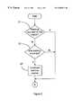
- a change in temperatureis calculated for the sensor at step 81 , and the change in temperature is compared to a predetermined temperature change at step 82 .
- the sensoris passed at step 83 .
- a checkis performed to determine whether the vehicle is in the run/fuel mode at step 84 . If the vehicle is in the run/fuel mode, a change in mileage is calculated for the vehicle at step 85 , and compared to a predetermined mileage change at step 86 .
- the number of warm-ups for the vehicleis compared to a predetermined number of warm-ups at step 87 . If the number of warm-ups reaches the predetermined number of warm-ups, the sensor is failed at step 88 .
- the pass/fail informationis passed to a rationality manager for use throughout the vehicle at step 89 . At step 90 , it is indicated that the test is done, and at step 91 , it is indicated that a retest on the next “key on” is desired.
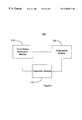
- FIG. 6demonstrates a vehicle temperature sensor diagnostic system 100 according to the present invention.
- Diagnostic system 100includes a fault status verification module 110 for verifying a fault status for the sensor (not shown).
- An initialization module 120initializes a mileage based diagnostic when the fault status indicates that no sensor faults are present.
- the diagnostic system 100further includes a diagnostic module 130 for conducting the mileage based diagnostic upon initialization.
- the diagnostic system 100is implemented in an engine controller for the vehicle as part of the on board diagnostics. Diagnostic system 100 may also be implemented, however, in a dedicated controller.
Landscapes
- Engineering & Computer Science (AREA)
- Chemical & Material Sciences (AREA)
- Combustion & Propulsion (AREA)
- Mechanical Engineering (AREA)
- General Engineering & Computer Science (AREA)
- Combined Controls Of Internal Combustion Engines (AREA)
Abstract
Description
Claims (20)
Priority Applications (1)
| Application Number | Priority Date | Filing Date | Title |
|---|---|---|---|
| US09/471,585US6208917B1 (en) | 1999-12-23 | 1999-12-23 | Ambient temperature/inlet air temperature sensor dither |
Applications Claiming Priority (1)
| Application Number | Priority Date | Filing Date | Title |
|---|---|---|---|
| US09/471,585US6208917B1 (en) | 1999-12-23 | 1999-12-23 | Ambient temperature/inlet air temperature sensor dither |
Publications (1)
| Publication Number | Publication Date |
|---|---|
| US6208917B1true US6208917B1 (en) | 2001-03-27 |
Family
ID=23872198
Family Applications (1)
| Application Number | Title | Priority Date | Filing Date |
|---|---|---|---|
| US09/471,585Expired - LifetimeUS6208917B1 (en) | 1999-12-23 | 1999-12-23 | Ambient temperature/inlet air temperature sensor dither |
Country Status (1)
| Country | Link |
|---|---|
| US (1) | US6208917B1 (en) |
Cited By (13)
| Publication number | Priority date | Publication date | Assignee | Title |
|---|---|---|---|---|
| US6598195B1 (en)* | 2000-08-21 | 2003-07-22 | General Electric Company | Sensor fault detection, isolation and accommodation |
| DE10221992C1 (en)* | 2002-05-17 | 2003-11-20 | Audi Ag | Method for testing the function of a temperature sensor provided in or on a drive unit |
| US6687601B2 (en) | 2002-03-21 | 2004-02-03 | Cummins, Inc. | System for diagnosing an air handling mechanism of an internal combustion engine |
| US20060149441A1 (en)* | 2004-12-21 | 2006-07-06 | Toyota Jidosha Kabushiki Kaisha | Failure detection device and method for oil temperature sensor for automatic transmission |
| US20060157001A1 (en)* | 2005-01-14 | 2006-07-20 | Mahfuzur Rahman | Method and apparatus to evaluate an intake air temperature monitoring circuit |
| US20060282200A1 (en)* | 2005-06-14 | 2006-12-14 | Christof Thiel | Method for error diagnosis of an ambient-pressure sensor and an intake-manifold pressure sensor |
| US20080133149A1 (en)* | 2006-12-05 | 2008-06-05 | Robert Louis Ponziani | Sensor fault detection and compensation |
| US20090182489A1 (en)* | 2008-01-16 | 2009-07-16 | Koon Chul Yang | Intake air temperature (iat) rationality diagnostic with an engine block heater |
| US20110066325A1 (en)* | 2009-09-11 | 2011-03-17 | Ford Global Technologies, Llc | Curve-related accident mitigation |
| CN102759451A (en)* | 2012-06-28 | 2012-10-31 | 广东电网公司电力科学研究院 | Steam turbine regulating system jam fault diagnosis method based on strong tracking Kalman filtering |
| US8868315B2 (en) | 2010-12-02 | 2014-10-21 | Toyota Motor Engineering & Manufacturing North America, Inc. | Systems and methods for estimating a temperature calibration |
| US8965716B2 (en) | 2010-04-05 | 2015-02-24 | Lear Corporation | Method and apparatus for testing at least one temperature sensor in a vehicle |
| US20190035399A1 (en)* | 2012-05-29 | 2019-01-31 | Samsung Electronics Co., Ltd. | Method and apparatus for executing voice command in electronic device |
Citations (19)
| Publication number | Priority date | Publication date | Assignee | Title |
|---|---|---|---|---|
| US4398258A (en) | 1979-12-26 | 1983-08-09 | Nippondenso Co., Ltd. | Malfunction procedure indicating system and method |
| US4615321A (en) | 1983-08-06 | 1986-10-07 | Daimler-Benz Aktiengesellschaft | Method and apparatus for checking sensors |
| US4882564A (en) | 1988-06-06 | 1989-11-21 | Monitech Corporation | Remote temperature monitoring system |
| US4949078A (en) | 1987-12-28 | 1990-08-14 | Aisin Aw Kabushiki Kaisha | Fail-safe operation of a vehicle automatic transmission responsive to failure of engine water temperature sensor |
| US5107246A (en) | 1990-02-20 | 1992-04-21 | Mitsubishi Denki Kabushiki Kaisha | Apparatus and method for determining a failure of a temperature sensor for an automatic transmission |
| US5153835A (en) | 1988-07-29 | 1992-10-06 | Mitsubishi Jidosha Kogyo Kabushiki Kaisha | Fail safe device for temperature sensor |
| US5235527A (en)* | 1990-02-09 | 1993-08-10 | Toyota Jidosha Kabushiki Kaisha | Method for diagnosing abnormality of sensor |
| US5243854A (en) | 1990-08-31 | 1993-09-14 | Mitsubishi Denki K.K. | Method of determining failure of sensors in a control device for an internal combustion engine |
| US5388454A (en) | 1990-09-05 | 1995-02-14 | Honda Giken Kogyo K.K. | Device for detecting deterioration of a catalyst temperature sensor |
| US5554969A (en) | 1994-02-02 | 1996-09-10 | Nissan Motor Co., Ltd. | Diagnosing apparatus and method for detecting failure in sensor applicable to motor-driven vehicular rear road wheel steering system |
| US5614664A (en)* | 1994-07-19 | 1997-03-25 | Unisia Jecs Corporation | Self diagnosis method and apparatus for a fuel temperature detection apparatus of an internal combustion engine |
| US5617337A (en) | 1993-10-20 | 1997-04-01 | Robert Bosch Gmbh | Method and device for monitoring sensor functions |
| US5815828A (en) | 1997-07-08 | 1998-09-29 | Chrysler Corporation | Method of measuring temperature of a catalytic converter |
| US5848381A (en) | 1996-10-03 | 1998-12-08 | Nissan Motor Co., Ltd. | Decision system for determining sensor failure of temperature sensor in automobile applications |
| US5880361A (en) | 1996-08-23 | 1999-03-09 | Toyota Jidosha Kabushiki Kaisha | Abnormality detecting apparatus for an air temperature sensor |
| US5884243A (en)* | 1996-03-24 | 1999-03-16 | Toyota Jidosha Kabushiki Kaisha | Diagnostic system for a cooling water temperature sensor |
| US5893893A (en) | 1990-05-29 | 1999-04-13 | Autotronics, Inc. | Device for the computerized recording of mileage and expenses in vehicles |
| US5948026A (en) | 1996-10-24 | 1999-09-07 | General Motors Corporation | Automotive data recorder |
| US5995887A (en)* | 1997-10-06 | 1999-11-30 | Ford Global Technologies, Inc. | Apparatus and method for determining a failure of an automatic transmission fluid temperature sensor |
- 1999
- 1999-12-23USUS09/471,585patent/US6208917B1/ennot_activeExpired - Lifetime
Patent Citations (19)
| Publication number | Priority date | Publication date | Assignee | Title |
|---|---|---|---|---|
| US4398258A (en) | 1979-12-26 | 1983-08-09 | Nippondenso Co., Ltd. | Malfunction procedure indicating system and method |
| US4615321A (en) | 1983-08-06 | 1986-10-07 | Daimler-Benz Aktiengesellschaft | Method and apparatus for checking sensors |
| US4949078A (en) | 1987-12-28 | 1990-08-14 | Aisin Aw Kabushiki Kaisha | Fail-safe operation of a vehicle automatic transmission responsive to failure of engine water temperature sensor |
| US4882564A (en) | 1988-06-06 | 1989-11-21 | Monitech Corporation | Remote temperature monitoring system |
| US5153835A (en) | 1988-07-29 | 1992-10-06 | Mitsubishi Jidosha Kogyo Kabushiki Kaisha | Fail safe device for temperature sensor |
| US5235527A (en)* | 1990-02-09 | 1993-08-10 | Toyota Jidosha Kabushiki Kaisha | Method for diagnosing abnormality of sensor |
| US5107246A (en) | 1990-02-20 | 1992-04-21 | Mitsubishi Denki Kabushiki Kaisha | Apparatus and method for determining a failure of a temperature sensor for an automatic transmission |
| US5893893A (en) | 1990-05-29 | 1999-04-13 | Autotronics, Inc. | Device for the computerized recording of mileage and expenses in vehicles |
| US5243854A (en) | 1990-08-31 | 1993-09-14 | Mitsubishi Denki K.K. | Method of determining failure of sensors in a control device for an internal combustion engine |
| US5388454A (en) | 1990-09-05 | 1995-02-14 | Honda Giken Kogyo K.K. | Device for detecting deterioration of a catalyst temperature sensor |
| US5617337A (en) | 1993-10-20 | 1997-04-01 | Robert Bosch Gmbh | Method and device for monitoring sensor functions |
| US5554969A (en) | 1994-02-02 | 1996-09-10 | Nissan Motor Co., Ltd. | Diagnosing apparatus and method for detecting failure in sensor applicable to motor-driven vehicular rear road wheel steering system |
| US5614664A (en)* | 1994-07-19 | 1997-03-25 | Unisia Jecs Corporation | Self diagnosis method and apparatus for a fuel temperature detection apparatus of an internal combustion engine |
| US5884243A (en)* | 1996-03-24 | 1999-03-16 | Toyota Jidosha Kabushiki Kaisha | Diagnostic system for a cooling water temperature sensor |
| US5880361A (en) | 1996-08-23 | 1999-03-09 | Toyota Jidosha Kabushiki Kaisha | Abnormality detecting apparatus for an air temperature sensor |
| US5848381A (en) | 1996-10-03 | 1998-12-08 | Nissan Motor Co., Ltd. | Decision system for determining sensor failure of temperature sensor in automobile applications |
| US5948026A (en) | 1996-10-24 | 1999-09-07 | General Motors Corporation | Automotive data recorder |
| US5815828A (en) | 1997-07-08 | 1998-09-29 | Chrysler Corporation | Method of measuring temperature of a catalytic converter |
| US5995887A (en)* | 1997-10-06 | 1999-11-30 | Ford Global Technologies, Inc. | Apparatus and method for determining a failure of an automatic transmission fluid temperature sensor |
Cited By (17)
| Publication number | Priority date | Publication date | Assignee | Title |
|---|---|---|---|---|
| US6598195B1 (en)* | 2000-08-21 | 2003-07-22 | General Electric Company | Sensor fault detection, isolation and accommodation |
| US6687601B2 (en) | 2002-03-21 | 2004-02-03 | Cummins, Inc. | System for diagnosing an air handling mechanism of an internal combustion engine |
| DE10221992C1 (en)* | 2002-05-17 | 2003-11-20 | Audi Ag | Method for testing the function of a temperature sensor provided in or on a drive unit |
| US20060149441A1 (en)* | 2004-12-21 | 2006-07-06 | Toyota Jidosha Kabushiki Kaisha | Failure detection device and method for oil temperature sensor for automatic transmission |
| US20060157001A1 (en)* | 2005-01-14 | 2006-07-20 | Mahfuzur Rahman | Method and apparatus to evaluate an intake air temperature monitoring circuit |
| US7120535B2 (en) | 2005-01-14 | 2006-10-10 | Delphi Technologies, Inc. | Method and apparatus to evaluate an intake air temperature monitoring circuit |
| US7463960B2 (en)* | 2005-06-14 | 2008-12-09 | Robert Bosch Gmbh | Method for error diagnosis of an ambient-pressure sensor and an intake-manifold pressure sensor |
| US20060282200A1 (en)* | 2005-06-14 | 2006-12-14 | Christof Thiel | Method for error diagnosis of an ambient-pressure sensor and an intake-manifold pressure sensor |
| US20080133149A1 (en)* | 2006-12-05 | 2008-06-05 | Robert Louis Ponziani | Sensor fault detection and compensation |
| US7481100B2 (en) | 2006-12-05 | 2009-01-27 | General Electric Company | Method and apparatus for sensor fault detection and compensation |
| US20090182489A1 (en)* | 2008-01-16 | 2009-07-16 | Koon Chul Yang | Intake air temperature (iat) rationality diagnostic with an engine block heater |
| US20110066325A1 (en)* | 2009-09-11 | 2011-03-17 | Ford Global Technologies, Llc | Curve-related accident mitigation |
| US8296033B2 (en)* | 2009-09-11 | 2012-10-23 | Ford Global Technologies, Llc | Curve-related accident mitigation |
| US8965716B2 (en) | 2010-04-05 | 2015-02-24 | Lear Corporation | Method and apparatus for testing at least one temperature sensor in a vehicle |
| US8868315B2 (en) | 2010-12-02 | 2014-10-21 | Toyota Motor Engineering & Manufacturing North America, Inc. | Systems and methods for estimating a temperature calibration |
| US20190035399A1 (en)* | 2012-05-29 | 2019-01-31 | Samsung Electronics Co., Ltd. | Method and apparatus for executing voice command in electronic device |
| CN102759451A (en)* | 2012-06-28 | 2012-10-31 | 广东电网公司电力科学研究院 | Steam turbine regulating system jam fault diagnosis method based on strong tracking Kalman filtering |
Similar Documents
| Publication | Publication Date | Title |
|---|---|---|
| US6208917B1 (en) | Ambient temperature/inlet air temperature sensor dither | |
| CN108627198B (en) | Method for providing diagnostics on a combined humidity and temperature sensor | |
| US20090182489A1 (en) | Intake air temperature (iat) rationality diagnostic with an engine block heater | |
| US7707868B2 (en) | Method for determining the operability of a pressure sensor | |
| US20170154479A1 (en) | Fault diagnosis method for vehicle | |
| JPS6378041A (en) | Fault diagnosing device for vehicle | |
| JPH10252635A (en) | Engine combustion state detection device with failure diagnosis device | |
| US11626629B2 (en) | Method for performing a test of a thermal management system | |
| CN113030619B (en) | Fault detection method and fault detection system of temperature sensor and vehicle | |
| JPH10512963A (en) | Inspection method of vehicle partial device in automobile | |
| JP2007047172A (en) | Failure detection method of ambient temperature sensor of automobile | |
| US10975794B2 (en) | Method of fault isolation for systems with existing diagnostics | |
| US6317681B2 (en) | Method for monitoring the operation of sensors in an internal combustion engine, and electronic controller operating in accordance with the method | |
| US10102690B2 (en) | Non-starting engine remote diagnostic | |
| US10096177B2 (en) | Electronic control unit | |
| JP2003515694A (en) | How to detect erroneous sensors | |
| CN112394282B (en) | Carbon tank electromagnetic valve diagnosis method, device, equipment and storage medium | |
| JP2003518224A (en) | Method for identifying sensor malfunction | |
| US8225646B2 (en) | Throttle body sweep diagnostic system and method | |
| JP2007322377A (en) | On-board failure diagnosis apparatus and method for testing same | |
| US20190242325A1 (en) | Fault diagnosis of electronic control unit (ecu) | |
| CN114641606A (en) | Method for managing contingent anomalies of a powertrain of a motor vehicle | |
| JP2004044407A (en) | Troubleshooting control device for vehicle | |
| KR101387421B1 (en) | Vehicle Analysis Apparatus Using Earth Level Signal | |
| Kotzan | On-board diagnostics for emission control systems |
Legal Events
| Date | Code | Title | Description |
|---|---|---|---|
| AS | Assignment | Owner name:DAIMLERCHRYSLER CORPORATION, MICHIGAN Free format text:ASSIGNMENT OF ASSIGNORS INTEREST;ASSIGNORS:MCKISSICK, GARRY W., JR.;JOHNSON, THOMAS M.;BOOMS, CHRIS J.;REEL/FRAME:010442/0332 Effective date:20000214 | |
| STCF | Information on status: patent grant | Free format text:PATENTED CASE | |
| FPAY | Fee payment | Year of fee payment:4 | |
| AS | Assignment | Owner name:SIEMENS VDO AUTOMOTIVE ELECTRONICS CORPORATION, AL Free format text:ASSIGNMENT OF ASSIGNORS INTEREST;ASSIGNOR:DAIMLERCHRYSLER CORPORATION;REEL/FRAME:016059/0722 Effective date:20040401 | |
| AS | Assignment | Owner name:SIEMENS VDO AUTOMOTIVE ELECTRONICS CORPORATION, AL Free format text:ASSIGNMENT OF ASSIGNORS INTEREST;ASSIGNOR:DAIMLERCHRYSLER CORPORATION;REEL/FRAME:016216/0035 Effective date:20040401 | |
| AS | Assignment | Owner name:WILMINGTON TRUST COMPANY, DELAWARE Free format text:GRANT OF SECURITY INTEREST IN PATENT RIGHTS - FIRST PRIORITY;ASSIGNOR:CHRYSLER LLC;REEL/FRAME:019773/0001 Effective date:20070803 Owner name:WILMINGTON TRUST COMPANY,DELAWARE Free format text:GRANT OF SECURITY INTEREST IN PATENT RIGHTS - FIRST PRIORITY;ASSIGNOR:CHRYSLER LLC;REEL/FRAME:019773/0001 Effective date:20070803 | |
| AS | Assignment | Owner name:WILMINGTON TRUST COMPANY, DELAWARE Free format text:GRANT OF SECURITY INTEREST IN PATENT RIGHTS - SECOND PRIORITY;ASSIGNOR:CHRYSLER LLC;REEL/FRAME:019767/0810 Effective date:20070803 Owner name:WILMINGTON TRUST COMPANY,DELAWARE Free format text:GRANT OF SECURITY INTEREST IN PATENT RIGHTS - SECOND PRIORITY;ASSIGNOR:CHRYSLER LLC;REEL/FRAME:019767/0810 Effective date:20070803 | |
| FPAY | Fee payment | Year of fee payment:8 | |
| AS | Assignment | Owner name:US DEPARTMENT OF THE TREASURY, DISTRICT OF COLUMBI Free format text:GRANT OF SECURITY INTEREST IN PATENT RIGHTS - THIR;ASSIGNOR:CHRYSLER LLC;REEL/FRAME:022259/0188 Effective date:20090102 Owner name:US DEPARTMENT OF THE TREASURY,DISTRICT OF COLUMBIA Free format text:GRANT OF SECURITY INTEREST IN PATENT RIGHTS - THIR;ASSIGNOR:CHRYSLER LLC;REEL/FRAME:022259/0188 Effective date:20090102 | |
| AS | Assignment | Owner name:CHRYSLER LLC, MICHIGAN Free format text:RELEASE BY SECURED PARTY;ASSIGNOR:US DEPARTMENT OF THE TREASURY;REEL/FRAME:022910/0273 Effective date:20090608 | |
| AS | Assignment | Owner name:CHRYSLER LLC, MICHIGAN Free format text:RELEASE OF SECURITY INTEREST IN PATENT RIGHTS - FIRST PRIORITY;ASSIGNOR:WILMINGTON TRUST COMPANY;REEL/FRAME:022910/0498 Effective date:20090604 Owner name:CHRYSLER LLC, MICHIGAN Free format text:RELEASE OF SECURITY INTEREST IN PATENT RIGHTS - SECOND PRIORITY;ASSIGNOR:WILMINGTON TRUST COMPANY;REEL/FRAME:022910/0740 Effective date:20090604 Owner name:NEW CARCO ACQUISITION LLC, MICHIGAN Free format text:ASSIGNMENT OF ASSIGNORS INTEREST;ASSIGNOR:CHRYSLER LLC;REEL/FRAME:022915/0001 Effective date:20090610 Owner name:THE UNITED STATES DEPARTMENT OF THE TREASURY, DIST Free format text:SECURITY AGREEMENT;ASSIGNOR:NEW CARCO ACQUISITION LLC;REEL/FRAME:022915/0489 Effective date:20090610 Owner name:CHRYSLER LLC,MICHIGAN Free format text:RELEASE OF SECURITY INTEREST IN PATENT RIGHTS - FIRST PRIORITY;ASSIGNOR:WILMINGTON TRUST COMPANY;REEL/FRAME:022910/0498 Effective date:20090604 Owner name:CHRYSLER LLC,MICHIGAN Free format text:RELEASE OF SECURITY INTEREST IN PATENT RIGHTS - SECOND PRIORITY;ASSIGNOR:WILMINGTON TRUST COMPANY;REEL/FRAME:022910/0740 Effective date:20090604 Owner name:NEW CARCO ACQUISITION LLC,MICHIGAN Free format text:ASSIGNMENT OF ASSIGNORS INTEREST;ASSIGNOR:CHRYSLER LLC;REEL/FRAME:022915/0001 Effective date:20090610 Owner name:THE UNITED STATES DEPARTMENT OF THE TREASURY,DISTR Free format text:SECURITY AGREEMENT;ASSIGNOR:NEW CARCO ACQUISITION LLC;REEL/FRAME:022915/0489 Effective date:20090610 | |
| AS | Assignment | Owner name:CHRYSLER GROUP LLC, MICHIGAN Free format text:CHANGE OF NAME;ASSIGNOR:NEW CARCO ACQUISITION LLC;REEL/FRAME:022919/0126 Effective date:20090610 Owner name:CHRYSLER GROUP LLC,MICHIGAN Free format text:CHANGE OF NAME;ASSIGNOR:NEW CARCO ACQUISITION LLC;REEL/FRAME:022919/0126 Effective date:20090610 | |
| AS | Assignment | Owner name:CHRYSLER GROUP GLOBAL ELECTRIC MOTORCARS LLC, NORT Free format text:RELEASE BY SECURED PARTY;ASSIGNOR:THE UNITED STATES DEPARTMENT OF THE TREASURY;REEL/FRAME:026343/0298 Effective date:20110524 Owner name:CHRYSLER GROUP LLC, MICHIGAN Free format text:RELEASE BY SECURED PARTY;ASSIGNOR:THE UNITED STATES DEPARTMENT OF THE TREASURY;REEL/FRAME:026343/0298 Effective date:20110524 | |
| AS | Assignment | Owner name:CITIBANK, N.A., NEW YORK Free format text:SECURITY AGREEMENT;ASSIGNOR:CHRYSLER GROUP LLC;REEL/FRAME:026404/0123 Effective date:20110524 | |
| AS | Assignment | Owner name:CITIBANK, N.A., NEW YORK Free format text:SECURITY AGREEMENT;ASSIGNOR:CHRYSLER GROUP LLC;REEL/FRAME:026435/0652 Effective date:20110524 | |
| FPAY | Fee payment | Year of fee payment:12 | |
| AS | Assignment | Owner name:JPMORGAN CHASE BANK, N.A., ILLINOIS Free format text:SECURITY AGREEMENT;ASSIGNOR:CHRYSLER GROUP LLC;REEL/FRAME:032384/0640 Effective date:20140207 | |
| AS | Assignment | Owner name:FCA US LLC, FORMERLY KNOWN AS CHRYSLER GROUP LLC, Free format text:RELEASE OF SECURITY INTEREST RELEASING SECOND-LIEN SECURITY INTEREST PREVIOUSLY RECORDED AT REEL 026426 AND FRAME 0644, REEL 026435 AND FRAME 0652, AND REEL 032384 AND FRAME 0591;ASSIGNOR:CITIBANK, N.A.;REEL/FRAME:037784/0001 Effective date:20151221 | |
| AS | Assignment | Owner name:FCA US LLC (FORMERLY KNOWN AS CHRYSLER GROUP LLC), Free format text:RELEASE BY SECURED PARTY;ASSIGNOR:CITIBANK, N.A.;REEL/FRAME:042885/0255 Effective date:20170224 | |
| AS | Assignment | Owner name:FCA US LLC (FORMERLY KNOWN AS CHRYSLER GROUP LLC), Free format text:RELEASE BY SECURED PARTY;ASSIGNOR:JPMORGAN CHASE BANK, N.A.;REEL/FRAME:048177/0356 Effective date:20181113 |