US6208895B1 - Circuit for performing external pacing and biphasic defibrillation - Google Patents
Circuit for performing external pacing and biphasic defibrillationDownload PDFInfo
- Publication number
- US6208895B1 US6208895B1US09/172,322US17232298AUS6208895B1US 6208895 B1US6208895 B1US 6208895B1US 17232298 AUS17232298 AUS 17232298AUS 6208895 B1US6208895 B1US 6208895B1
- Authority
- US
- United States
- Prior art keywords
- circuit
- pulse
- pacing
- storage capacitor
- defibrillation
- Prior art date
- Legal status (The legal status is an assumption and is not a legal conclusion. Google has not performed a legal analysis and makes no representation as to the accuracy of the status listed.)
- Expired - Lifetime
Links
Images


Classifications
- A—HUMAN NECESSITIES
- A61—MEDICAL OR VETERINARY SCIENCE; HYGIENE
- A61N—ELECTROTHERAPY; MAGNETOTHERAPY; RADIATION THERAPY; ULTRASOUND THERAPY
- A61N1/00—Electrotherapy; Circuits therefor
- A61N1/18—Applying electric currents by contact electrodes
- A61N1/32—Applying electric currents by contact electrodes alternating or intermittent currents
- A61N1/38—Applying electric currents by contact electrodes alternating or intermittent currents for producing shock effects
- A61N1/39—Heart defibrillators
- A61N1/3904—External heart defibrillators [EHD]
- A—HUMAN NECESSITIES
- A61—MEDICAL OR VETERINARY SCIENCE; HYGIENE
- A61N—ELECTROTHERAPY; MAGNETOTHERAPY; RADIATION THERAPY; ULTRASOUND THERAPY
- A61N1/00—Electrotherapy; Circuits therefor
- A61N1/18—Applying electric currents by contact electrodes
- A61N1/32—Applying electric currents by contact electrodes alternating or intermittent currents
- A61N1/38—Applying electric currents by contact electrodes alternating or intermittent currents for producing shock effects
- A61N1/39—Heart defibrillators
- A61N1/3906—Heart defibrillators characterised by the form of the shockwave
- A61N1/3912—Output circuitry therefor, e.g. switches
Definitions
- This inventionrelates generally to apparatus for generating stimulation waveforms, and more particularly to a circuit for generating both pacing and defibrillation waveforms in an external unit.
- ventricular fibrillationa condition where the human heart is unable to pump the volume of blood required by the human body.
- the generally accepted technique for restoring a normal rhythm to a heart experiencing ventricular fibrillationis to apply a strong electric pulse to the heart using an external cardiac defibrillator.
- External cardiac defibrillatorshave been successfully used for many years in hospitals by doctors and nurses, and in the field by emergency treatment personnel, e.g., paramedics.
- Conventional external cardiac defibrillatorsfirst accumulate a high-energy electric charge on an energy storage capacitor. When a switching mechanism is closed, the stored energy is transferred to a patient in the form of a large current pulse. The current pulse is applied to the patient via a pair of electrodes positioned on the patient's chest.
- the switching mechanism used in most contemporary external defibrillatorsis a high-energy transfer relay. A discharge control signal causes the relay to complete an electrical circuit between the storage capacitor and a wave shaping circuit whose output is connected to the electrodes attached to the patient.
- biphasic waveformmay limit the resulting heart trauma associated with the defibrillation pulse.
- the American Heart Associationhas recommended a range of energy levels for the first three defibrillation pulses applied by an external defibrillator.
- the recommended energy levelsare: 200 joules for a first defibrillation pulse; 200 or 300 joules for a second defibrillation pulse; and 360 joules for a third defibrillation pulse, all within a recommended variance range of no more than plus or minus 15 percent according to standards promulgated by the Association for the Advancement of Medical Instrumentation (AAMI).
- AAMIAdvancement of Medical Instrumentation
- pacersare typically used to administer a series of relatively small electrical pulses to a patient experiencing an irregular heart rhythm.
- each pacing pulsetypically has an energy of about 0.05 J to 1.2 J. Because of the small energies used for pacing pulses, the circuitry used to generate the pacing pulses cannot typically be used for generating defibrillation pulses.
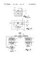
- FIG. 1shows a combined pacing defibrillation unit 5 having a defibrillation circuit 6 and a pacing circuit 7 .
- Unit 5selectively delivers defibrillation or pacing pulses to the patient.
- Implantable systemsgenerally use separate electrodes for pacing and defibrillation.
- An example of an implantable combined defibrillator/paceris found in U.S. Pat. No. 5,048,521.
- the present inventionis directed to an apparatus that overcomes the foregoing and other disadvantages in an external pacing/defibrillation unit. More specifically, the present invention is directed to a single output circuit for an external pacer/defibrillator that is capable of applying both high-energy biphasic defibrillation pulses and low-energy pacing pulses to a patient.
- an external defibrillator/pacerhaving an output circuit that is used in generating both a defibrillation pulse and a pacing pulse.
- the output circuitincludes four legs arrayed in the form of an “H” (hereinafter the “H-bridge output circuit”). Each leg of the output circuit contains a solid-state switch. By selectively switching on pairs of switches in the H-bridge output circuit, biphasic or monophasic defibrillation and pacing pulses may be applied to a patient.
- the switches in three of the legs of the H-bridge output circuitare silicon controlled rectifiers (SCRs).
- SCRssilicon controlled rectifiers
- a single SCRis used in each of these three legs.
- the switch in the fourth legis an insulated gate bipolar transistor (IGBT).
- IGBTinsulated gate bipolar transistor
- the bypass circuitis capable of conducting the relatively small pacing currents, which are generally too small to trigger the SCRs required to conduct the relatively large defibrillation currents.
- the addition of the bypass circuiteliminates the need for separate defibrillation and pacing output circuits.
- the H-bridge output circuithas two IGBT legs and two SCR legs.
- the second IGBT legallows the polarity of the defibrillation and pacing pulses to be opposite.
- the pacing currentis adjusted by adjusting the voltage on an energy storage capacitor.
- an adjustable current sourceis used to provide the pacing current.
- This current sourceis coupled to the energy storage capacitor.
- the current sourceis an IGBT operated in the linear region.
- all of the H-bridge legsare implemented with IGBTs. This aspect allows for generation of biphasic pacing pulses. Further, by biasing the IGBTs in the linear region, the IGBTs can be used as current sources to control the pacing current. This would eliminate the need for a bypass circuit or separate current source.
- FIG. 1is a block diagram of a conventional combined defibrillator/pacer unit.
- FIG. 2is a block diagram illustrative of a combined defibrillator/pacer unit having a single output circuit, according to one embodiment of the present invention.
- FIG. 3is a flow diagram illustrative of the operation of the combined defibrillator/pacer unit depicted in FIG. 2 .
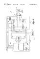
- FIG. 4is a more detailed block diagram illustrative of the combined defibrillator/pacer unit depicted in FIG. 2 .
- FIG. 5is a schematic diagram illustrative of the block diagram depicted in FIG. 4 .
- FIG. 6is a flow diagram illustrative of the operation of the combined defibrillator/pacer unit depicted in FIG. 5 .
- FIG. 7is a diagram illustrative of the waveforms generated by the combined defibrillator/pacer unit depicted in FIG. 5, according to one embodiment of the present invention.
- FIG. 8is a block diagram illustrative of another embodiment of a combined defibrillator/pacer unit, according to the present invention.
- FIG. 9is a diagram illustrative of the waveforms generated by the combined defibrillator/pacer unit depicted in FIG. 8, according to one embodiment of the present invention.
- FIG. 10is a schematic diagram of an IGBT driver for linear control of an IGBT, according to one embodiment of the present invention.
- FIG. 11is a flow diagram illustrative of the operation of the combined defibrillator/pacer unit depicted in FIG. 8 .
- FIG. 12is a block diagram illustrative of a combined defibrillator/pacer unit, according to yet another embodiment of the present invention.
- FIG. 13is a diagram illustrative of various waveforms generated by the combined defibrillator/pacer unit depicted in FIG. 12 .
- FIG. 14is a block diagram illustrative of a combined defibrillator/pacer unit, according to still another embodiment of the present invention.
- FIG. 15is a diagram illustrative of current sensing circuit, according to one embodiment of the present invention.
- FIG. 2is a block diagram illustrative of an external combined defibrillator/pacer 8 , according to one embodiment of the present invention.
- Combined external defibrillator/pacer 8includes a control circuit 10 , an H-bridge 14 , electrodes 15 a and 15 b, a charging circuit 18 , and an energy storage capacitor 24 .
- Defibrillator/pacer 8is interconnected as follows. Control circuit 10 is connected to charging circuit 18 and H-bridge 14 . Charging circuit 18 is connected to energy storage capacitor 24 . H-bridge 14 is connected to the electrodes of energy storage capacitor 24 , and also to electrodes 15 a and 15 b . Electrodes 15 a and 15 b are used to administer defibrillation and pacing pulses transcutaneously to a patient. The operation of defibrillator/pacer 8 is described below in conjunction with FIG. 3 .
- FIG. 3is a flow diagram illustrative of the operation of defibrillator/pacer 8 .
- defibrillator/pacer 8operates as follows.
- a step 70defibrillator/pacer 8 decides whether pacing or defibrillation pulses are appropriate for the patient. Alternatively, the user may make this determination. If pacing pulses are appropriate, in a next step 71 , defibrillator/pacer 8 is configured to generate pacing pulses.
- control circuit 10can control charging circuit 18 to charge energy storage capacitor 24 to a desired level for pacing.
- defibrillator/pacer 8generates a pacing pulse using H-bridge 14 .
- control circuit 10may be configured to control H-bridge 14 to generate monophasic or biphasic pacing pulses of different polarities.
- a next step 73it is determined whether defibrillator/pacer 8 should remain in the pacing mode. If defibrillator/pacer 8 is to remain in the pacing mode, the process returns to step 71 . Otherwise, a step 74 is performed in which external combined defibrillator/pacer 8 returns to a standby mode.
- step 70it is determined that a defibrillation pulse is appropriate, in a step 75 , defibrillator/pacer 8 is configured to generate a defibrillation pulse.
- step 76defibrillator/pacer 8 generates a defibrillation pulse using H-bridge 14 . The generation of a defibrillation pulse is described further below in conjunction with FIG. 4 .
- step 77the process returns to the standby mode.
- FIG. 4is a more detailed block diagram of external combined defibrillator/pacer 8 that is connected to a patient 16 .
- the defibrillatorincludes a microprocessor 20 that is connected to energy storage capacitor 24 via charging circuit 18 .
- energy storage capacitor 24may be implemented with a multi-capacitor network (i.e., with capacitors connected in series and/or parallel).
- microprocessor 20controls charging circuit 18 using a signal on a control line 25 to charge energy storage capacitor 24 to a desired voltage level.
- microprocessor 20is connected to a scaling circuit 22 by a pair of measurement lines 47 and 48 , and by a control line 49 .
- Scaling circuit 22is connected to energy storage capacitor 24 by a bridge line 28 , which connects to the negative lead of energy storage capacitor 24 , and by a line 30 , which connects to the positive lead of the capacitor.
- a clock 21is also connected to microprocessor 20 .
- Scaling circuit 22is used to step down the voltage across energy storage capacitor 24 to a range that may be monitored by microprocessor 20 .
- Scaling circuit 22is described briefly below and in more detail in an application entitled “Method and Apparatus for Verifying the Integrity of an Output Circuit Before and During Application of a Defibrillation Pulse”, U.S. patent application Ser. No. 08/811,834, filed Mar. 5, 1997, and incorporated herein by reference.
- Energy storage capacitor 24can be charged to a range of voltage levels, with the selected level depending on the patient and other parameters.
- the size of energy storage capacitor 24falls within a range from 150 ⁇ F to 200 ⁇ F.
- energy storage capacitor 24is charged to between 100 volts and 2,200 volts.
- scaling circuit 22is adjustable to measure different voltage ranges. The adjusted output is measured by microprocessor 20 on measurement line 48 .
- H-bridge 14is provided to allow the controlled transfer of energy from energy storage capacitor 24 to patient 16 .
- H-bridge 14is an output circuit that includes four switches 31 , 32 , 33 , and 34 . Each switch is connected in a leg of the output circuit that is arrayed in the form of an “H”.
- Switches 31 and 33are coupled through a protective component 27 to the positive lead of the energy storage capacitor 24 by a bridge line 26 .
- Protective component 27limits the current and voltage changes from energy storage capacitor 24 , and has both inductive and resistive properties.
- Switches 32 and 34are coupled to energy storage capacitor 24 by a bridge line 28 .
- Patient 16is connected to the left side of H-bridge 14 by an apex line 17 , and to the right side of H-bridge 14 by a sternum line 19 .
- apex line 17 and sternum line 19are connected to electrodes 15 a and 15 b , respectively, by a patient isolation relay 35 .
- Microprocessor 20is connected to switches 31 , 32 , 33 , and 34 by control lines 42 a , 42 b , 42 c , and 42 d , respectively, and to patient isolation relay 35 by control line 36 .
- a bypass circuit 40is connected between bridge line 26 and apex line 17 .
- Bypass circuit 40is also connected to receive a control signal from microprocessor 20 through control line 42 e .
- Bypass circuit 40is implemented with a switch to bypass switch 33 when generating pacing pulses, as described below.
- microprocessor 20through appropriate application of the control signals, causes switches 31 - 34 to be appropriately opened and closed and bypass circuit 40 to be closed, thereby allowing H-bridge 14 to conduct energy from storage capacitor 24 to the patient in the form of a monophasic pacing pulse.
- Bypass circuit 40is needed to bypass switch SW 33 because an SCR is used to implement this switch. More specifically, at the size required to handle the defibrillation energies, the SCR generally cannot be triggered by a typical pacing pulse current.
- H-bridge 14uses four output switches SW 1 -SW 4 to conduct energy from energy storage capacitor 24 to patient 16 .
- Switches SWI, SW 3 and SW 4are semiconductor switches, preferably silicon controlled rectifiers (SCRs).
- Switch SW 2is a series combination of switches SW 2 A and SW 2 B, preferably both insulated gate bipolar transistors (IGBTs).
- the IGBTsare model IXHS1718 IGBTs available from IXYS, Santa Clara, Calif. Two model IXHS1718 IGBTs are used in “series” to withstand the maximum voltage that may occur across switch SW 2 in H-bridge 14 so that the voltage across the entire switch SW 2 is divided between the two IGBTs.
- Switches SW 1 -SW 4can be switched from an off(non-conducting) to an on (conducting) condition.
- defibrillator/pacer 8In the defibrillation mode, defibrillator/pacer 8 generates a biphasic defibrillation pulse for application to the patient 16 .
- switches SW 1 -SW 4are opened.
- Charging of energy storage capacitor 24is started, and monitored by microprocessor 20 (FIG. 4 ).
- microprocessor 20FIG. 4
- switches SW 1 and SW 2are switched on so as to connect energy storage capacitor 24 with apex line 17 and sternum line 19 for the application of a first phase of a defibrillation pulse to patient 16 .
- the stored energytravels from the positive terminal of energy storage capacitor 24 on line 26 , through switch SW 1 and apex line 17 , across patient 16 , and back through sternum line 19 and switch SW 2 to the negative terminal of energy storage capacitor 24 on line 28 .
- the first phase of the biphasic pulseis therefore a positive pulse from the apex to the sternum of patient 16 .
- switch SW 2is biased off to prepare for the application of the second phase of the biphasic pulse.
- switch SW 2Once switch SW 2 is biased off, switch SW 1 will also become non-conducting because the voltage across the SCR falls to zero.
- switches SW 3 and SW 4are switched on to start the second phase of the biphasic pulse.
- Switches SW 3 and SW 4provide a current path to apply a negative defibrillation pulse to patient 16 .
- the energytravels from the positive terminal of energy storage capacitor 24 on line 26 , through switch SW 3 and sternum line 19 , across patient 16 , and back through apex line 17 and switch SW 4 to the negative terminal of energy storage capacitor 24 on line 28 .
- the polarity of the second phase of the defibrillation pulseis therefore opposite in polarity to the first phase of the biphasic pulse.
- the end of the second phase of the biphasic pulseis truncated by switching on switch SW 1 to provide a shorted path for the remainder of the capacitor energy through switches SW 1 and SW 4 .
- switches SW 1 -SW 4are switched off.
- Patient isolation relay 35is then opened. Energy storage capacitor 24 may then be recharged to prepare defibrillator/pacer 8 to apply another defibrillation pulse or to apply pacing pulses.
- the four output switches SW 1 -SW 4can be switched from an off (nonconducting) state to an on (conducting) state by application of appropriate control signals on control lines 42 a , 42 b , 42 c , and 42 d .
- special switch driving circuits 51 , 52 , 53 and 54are coupled to switches SW 1 -SW 4 , respectively.
- Control lines 42 a , 42 b , 42 c , and 42 dare connected to switch driving circuits 51 , 52 , 53 , and 54 , to allow microprocessor 20 to control the state of the switches.
- Switch driving circuits 51 , 53 and 54are identical. For purposes of this description, therefore, only the construction and operation of switch driving circuit 51 will be described. Those skilled in the art will recognize that switch driving circuits 53 and 54 operate in a similar manner.
- Switch driving circuit 51includes a control switch SW 11 , resistors R 11 , R 12 , and R 13 , a capacitor C 11 , a diode D 11 and a high-voltage transformer T 11 .
- Resistor R 11is connected between the positive voltage supply V′+ and the dotted end of the primary winding of transformer T 11 , and capacitor C 11 is connected between ground and the dotted end of the primary winding of transformer T 11 .
- Resistor R 12is connected between the non-dotted end of the primary winding of transformer T 11 and the drain of control switch SW 11 .
- Resistors R 11 and R 12 and capacitor C 11limit and shape the current and voltage waveforms across the primary winding of transformer T 11 .
- the source of control switch SW 11is connected to ground, and the gate of control switch SW 11 is connected to control line 42 a.
- the anode of diode D 1is connected to the dotted end of the secondary winding of transformer T 11 , and the cathode of diode D 11 is connected to the gate of SCR switch SW 1 .
- Resistor R 13is connected between the cathode of diode D 11 and the non-dotted end of the secondary winding of transformer T 11 .
- the non-dotted end of the secondary winding of transformer T 11is connected to the cathode of SCR switch SW 1 .
- an oscillating control signalis provided on control line 42 a .
- the oscillating control signalis a pulse train.
- the pulse train control signalrepeatedly turns control switch SW 11 on and off, producing a changing voltage across the primary winding of transformer T 11 .
- the voltageis stepped down by transformer T 11 and rectified by diode D 11 before being applied to the gate of SCR switch SW 1 .
- a 10% duty cycle pulse train on the control line 42 ahas been found to be adequate to maintain SCR switch SW 1 in a conducting state. As long as the control signal is applied to the switch driving circuit 51 , the switch SW 1 will remain in the conducting state.
- the switch SW 1remains in the conducting state even when conducting relatively low defibrillation currents.
- the SCR switchescan conduct currents as low as 90 mA.
- an SCRonce triggered or latched on, an SCR generally remains in the conducting state until the current through the SCR drops below a minimum level, even if the gate voltage of the SCR is grounded. Thus, when the current through the SCR switch would not be 90 mA or greater, the SCR would not conduct. Thus, SCRs are generally not practical for pacing applications.
- Switch driving circuit 52includes a capacitor C 21 , a transformer T 21 , and two identical switch driving circuits 52 A and 52 B, each circuit corresponding to one of the IGBTs.
- capacitor C 21is connected between control line 42 b and the non-dotted end of the primary winding of transformer T 21 .
- the dotted end of the primary winding of transformer T 21is grounded.
- Transformer T 21has two secondary windings T 21 A and T 21 B, one for each of switch driving circuits 52 A and 52 B.
- Switch driving circuits 52 A and 52 Bare identical, and therefore only the construction and operation of switch driving circuit 52 A will be described.
- Switch driving circuit 52 Aincludes diodes D 21 , D 22 , 23 , and D 24 , Zener diode ZD 21 , capacitors C 22 , C 23 , C 24 , and C 25 , resistors R 21 , 22 , R 23 , and R 24 , a PNP switch SW 23 , and an SCR switch SW 22 .
- the anodes of diodes D 21 , D 22 , and D 23are connected to the non-dotted end of secondary winding T 21 A of transformer T 21 .
- the cathodes of diodes D 21 and D 22are connected to the gate of IGBT switch SW 2 A.
- Resistor R 21 and capacitor C 22are connected between the dotted end of secondary winding T 21 A of transformer T 21 and the cathode of diode D 23 .
- the anode of SCR switch SW 22 and the cathode of Zener diode ZD 21are connected to the gate of IGBT switch SW 2 A.
- the cathode of SCR switch SW 22 and the anode of Zener diode ZD 21are connected to the dotted end of secondary winding T 2 IA of transformer T 21 , and also to the emitter of IGBT switch SW 2 A.
- Resistor R 23 and capacitor C 24are connected between the gate of IGBT switch SW 2 A and the emitter of PNP switch SW 23 .
- Resistor R 24 and capacitor C 25are connected between the emitter of PNP switch SW 23 and the dotted end of secondary winding T 21 A of transformer T 21 .
- the gate of SCR switch SW 22is connected to the collector of PNP switch SW 23 .
- Resistor R 22is connected between the collector of PNP switch SW 23 and the dotted end of secondary winding T 21 A of transformer T 21 .
- Capacitor C 23is connected between the emitter and the base of PNP switch SW 23 .
- the anode of diode D 24is connected to the base of PNP switch SW 23
- the cathode of diode D 24is connected to the cathode of diode D 23 .
- an oscillating control signalis provided on control line 42 b .
- the oscillating control signalis a pulse train.
- the pulse train control signalis stepped up in voltage by transformer T 21 and applied to the input of switch driving circuit 52 A.
- diodes D 21 and D 22rectify the current that travels through secondary winding T 21 A to charge capacitors C 24 and C 25 .
- some currentalso travels through diode D 23 to charge capacitor C 22 .
- Capacitor C 21limits the current in the primary winding of transformer T 21 , which correspondingly limits the current in secondary winding T 21 A.
- the secondary winding currentdetermines the charging time of the capacitors C 24 and C 25 . Since the voltage across capacitors C 24 and C 25 is also the voltage on the gate of IGBT switch SW 2 A, a slow accumulation of voltage on capacitors C 24 and C 25 therefore results in a slow turn on of IGBT switch SW 2 A.
- the charging currentis selected so that IGBT switch SW 2 A is turned on relatively slowly when compared to the fast turn on of SCR switches SWI, SW 3 , and SW 4 .
- a slow turn-on for IGBT switch SW 2 Ais desirable because the IGBT switches are on the same side of H-bridge 14 as SCR switch SW 3 .
- SCR switch SW 3is controlled by the control signal on control line 42 c , but due to the nature of SCR switches, the SCR switch may be accidentally turned on regardless of the signal on control line 42 c if a rapid voltage change occurs across SCR switch SW 3 . If IGBT switches SW 2 A and SW 2 B were therefore turned on too quickly, the resulting rate of change of the voltage across SCR switch SW 3 might cause it to turn on accidentally.
- Zener diode ZD 21protects IGBT switch SW 2 A by regulating the maximum voltage across capacitors C 24 and C 25 . Without Zener diode ZD 21 , the voltage on the gate of IGBT switch SW 2 A would rise to a level that would damage IGBT switch SW 2 A.
- diode D 23rectifies the current that travels through secondary winding T 21 A to charge capacitor C 22 .
- the charge on capacitor C 22which is replenished on each positive pulse of the pulse train control signal, maintains the voltage across the base of PNP switch SW 23 above the turn-on level for the PNP switch.
- PNP switch SW 23turns on if the base voltage on the switch drops below a threshold level. As will be described below, PNP switch SW 23 is only turned on when IGBT switch SW 2 A is to be turned off. Capacitor C 23 and diode D 24 are also provided to prevent PNP switch SW 23 from turning on.
- Capacitor C 23serves as a high frequency filter to prevent the high frequency driving pulses of switch driving circuit 52 A from causing PNP switch SW 23 to spuriously turn on.
- Diode D 24prevents a large negative base-emitter voltage from occurring which could cause PNP switch SW 23 to enter reverse breakdown.
- resistor R 21Since some discharging of capacitor C 22 occurs through resistor R 21 between positive pulses of the control signal on control line 42 b , resistor R 21 must be large enough to limit the discharging current flow from capacitor C 22 between the pulses. Limiting the current flow prevents the voltage on capacitor C 22 from dropping below the threshold level sufficient to turn on PNP switch SW 23 between pulses of the control signal. Then, during a positive pulse of the pulse train control signal on control line 42 b , the charging of capacitor C 22 must be sufficient to counteract the discharging that occurred since the previous positive pulse so as to return capacitor C 22 to its fully charged level by the end of the positive pulse.
- a 2 MHz pulse train control signal with a 25% duty cycle on the control line 42 bhas been found to be adequate to maintain the conducting state of IGBT switches SW 2 A and SW 2 B.
- the switcheswill remain conducting as long as the control signal is present, and regardless of the current flowing through the switches. Conversely, when the control signal is not present, IGBT switches SW 2 A and SW 2 B will be non-conductive.
- the maximum current that may generally occur in H-bridge 14results from the undesirable situation where a user of defibrillator/pacer 8 places the two shock paddles directly in contact with one another. When this happens, a short circuit is created between apex line 17 and sternum line 19 . During a short circuit, a brief current of up to 400 amps can result.
- IGBT switches SW 2 A and SW 2 Bare biased by a thirty volt gate voltage. Biasing the IGBTs at this voltage level is successful since the IGBT switches are used in a pulsed manner. If IGBT switches SW 2 A and SW 2 B were driven continuously for long periods of time with thirty volts on their gates, they might be damaged, but in H-bridge 14 , they are only driven at this level for very brief intervals.
- the turnoff of the IGBT switchesis performed relatively quickly.
- the IGBT switchesmay be quickly turned off because at turn-off there is no concern that the sensitive SCR switches will accidentally turn on.
- a fast turn-offis desirable to reduce the time that an IGBT switch would be subjected to a high voltage if one of the IGBT switches is inadvertently turned off before the other.
- IGBT switches SW 2 A and SW 2 Bare turned off when the pulse train control signal on control line 42 b is removed. Once positive voltage pulses are no longer being induced in the secondary windings of transformer T 21 , driving circuits 52 A and 52 B begin the turn-off process. Again, the turn-off process will only be described with respect to driving circuit 52 A since the circuits are essentially identical.
- capacitor C 22begins discharging through resistor R 21 . Since the RC time constant of capacitor C 22 and resistor R 21 is much smaller than the RC time constant of capacitors C 24 and C 25 and resistors R 23 and R 24 , the discharging of capacitor C 22 occurs much more quickly than the discharging of capacitors C 24 and C 25 .
- PNP switch SW 23is turned on. The threshold voltage level is equivalent to the base turn-on voltage of PNP switch SW 23 , plus the voltage drop across diode D 24 . Once PNP switch SW 23 is turned on, discharge current from capacitor C 25 begins to flow through the switch. As the current increases, the voltage across resistor R 22 correspondingly increases.
- special driving circuits 52 A and 52 Ballow the IGBTs to be used in external defibrillator/pacer 8 where extremely high voltages must be switched in the presence of SCRs.
- the driving circuitsminimize the number of components required to switch a defibrillation pulse of 200 or more joules.
- the IGBTsare also able to conduct very low currents that are associated with defibrillation pulses of less than 50 joules.
- each switch SW 1 -SW 4is also connected in parallel with a switch protection circuit 61 , 62 , 63 , and 64 , respectively.
- the switch protection circuitsare designed to prevent spurious voltage spikes from damaging the switches in H-bridge 14 .
- Switch protection circuits 61 , 63 and 64are identical and therefore only the construction and operation of switch protection circuit 61 will be described.
- Switch protection circuit 61includes a diode D 12 .
- the cathode of diode D 12is connected to the anode of SCR switch SW 1 , and the anode of diode D 12 is connected to the cathode of SCR switch SW 1 .
- Diode D 12protects SCR switch SW 1 against negative inductive spikes that may occur due to cable or load inductance.
- Switch protection circuit 62includes two identical switch protection circuits 62 A and 62 B, which protect IGBT switches SW 2 A and SW 2 B, respectively. Since switch protection circuits 62 A and 62 B are essentially identical, only the construction and operation of switch protection circuit 62 A will be described.
- Switch protection circuit 62 Aincludes a diode D 24 and a resistor R 23 . Resistor R 23 is connected between the collector and the emitter of IGBT switch SW 2 A. The cathode of diode D 24 is connected to the collector of IGBT switch SW 2 A, and the anode of diode D 24 is connected to the emitter of IGBT switch SW 2 A.
- Diode D 24operates similarly to diode D 12 as described above in that it protects IGBT switch SW 2 A against negative inductive spikes.
- Resistor R 23(in conjunction with resistor R 23 ′) ensures that the voltage across the two IGBT switches SW 2 A and SW 2 B is equally divided when H-bridge 14 is at rest. Dividing the voltage across IGBT switches SW 2 A and SW 2 B is important due to the limitations of present IGBT technology, which limits the rating of each IGBT switch to 1200V. In a system where the total maximum voltage is 2200V, the maximum voltage ratings are therefore obeyed by dividing the maximum voltage across each IGBT switch.
- protective component 27which has both inductive and resistive properties.
- protective circuit 27is implemented with coil of resistance wire that provides an inductive resistance.
- Protective component 27limits the rate of change of the voltage across, and current flow to, SCR switches SW 1 , SW 3 , and SW 4 . Too high of a rate of change of the voltage across an SCR switch is undesirable because it can cause the SCR switch to inadvertently turn on. For example, since SCR switches SW 1 and SW 4 are on the same side of H-bridge 14 , any time SCR switch SW 4 is abruptly turned on, a rapid voltage change may also result across SCR switch SW 1 .
- protective component 27reduces the rate of change of the voltage across SCR switch SW 1 when SCR switch SW 4 is turned on. Also, too high of a current flow can damage the switches SWI, SW 3 and SW 4 , and protective component 27 limits the current flow in H-bridge 14 . The use of protective component 27 therefore reduces the need for additional protective components that would otherwise need to be coupled to switches SW 1 , SW 3 and SW 4 .
- H-bridge 14allows external defibrillator/pacer 8 to generate and apply a high-energy biphasic waveform to a patient.
- the standard energy level in the industry for the dischargehas been greater than 200 joules.
- the above described circuitallows the same amount of energy (more than 200 joules) to be delivered to the patient in a biphasic waveform, thereby resulting in a greater certainty of defibrillation effectiveness for a broader range of patients.
- the circuitincorporates special driving circuitry to allow even very low energy biphasic waveforms (less than fifty joules) to be delivered to the patient.
- defibrillation mode operationis similar to the operation of the external defibrillator circuit disclosed in co-pending and commonly assigned U.S. patent application Ser. No. 08/811,833 filed Mar. 5, 1997, entitled “H-Bridge Circuit For Generating A High-Energy Biphasic Waveform In An External Defibrillator” by J. L. Sullivan et al.
- this embodiment of defibrillator/pacer 8generates a biphasic defibrillation pulse with a positive first phase and a negative second phase (measured from apex line 17 to sternum line 19 ).
- defibrillator/pacer 8operates as follows. Initially, switches SW 1 -SW 4 and bypass circuit 40 are opened. Once configured in the pacing mode, in a step 80 , control circuit 10 determines whether to generate a pacing pulse. If no pacing pulse is to be generated, the process returns to the standby mode in a step 81 .
- control circuit 10causes charging circuit 18 to charge energy storage capacitor 24 to a capacitor voltage level of about twenty-five to three hundred volts.
- the capacitor voltage levelwould vary according to desired pacing current for the pending pacing pulse, as described below.
- control circuit 10causes a relay K 4 in bypass circuit 40 to close.
- relay K 4is implemented with two model RTD19005 relays available from Potter-Bromfield, Princeton, Ind.
- RTD19005relays available from Potter-Bromfield, Princeton, Ind.
- Resistor R 4has a value of about five hundred ohms to help limit the short circuit current if the paddles touch.
- control circuit 10pulses on IGBTs SW 2 A and SW 2 B to allow a monophasic pacing pulse to be applied to patient 16 .
- control circuit 10controls the duration that IGBTs SW 2 A and SW 2 B are pulsed on to be equal to the desired duration of the monophasic pacing pulse. For a given capacitance value of energy storage capacitor 24 , the droop of the pacing pulses would vary according to patient impedance.
- control circuit 10measures the pacing current as the pacing pulse is being applied to patient 16 .
- the pacing currentis measured by monitoring the voltage drop across resistor R 4 .
- the pacing currentcan be measured by monitoring the change in voltage of energy storage capacitor 24 .
- control circuit 20determines the capacitor voltage level across energy storage capacitor 24 that is required for the next pacing pulse.
- the current of the next pacing pulseis increased by about 5 mA. That is, during pacing, the pacing current is increased in 5 mA increments until the pacing pulses are of sufficient strength to cause the heart muscle to contract or to a maximum of about 200 mA. The process then returns to step 80 to generate the next pacing pulse.
- the pacing pulses generated by this embodimentare positive (measured from apex line 17 to sternum line 19 ). However, because the polarity of a pacing pulse affects pacing capture threshold, the general practice is to generate pacing pulses that are negative. Negative pacing pulses can be generated by simply by switching apex and sternum lines 17 and 19 .
- FIG. 7shows waveforms representing the waveforms generated by this alternative embodiment. Waveform 90 represents a biphasic defibrillation pulse generated by this alternative, while waveform 91 represents a monophasic pacing pulse sequence.
- defibrillation waveform 90has a negative first phase 93 and a positive second phase 94 .
- Pacing waveform 91has negative monophasic pulses 96 , 97 and so on.
- the biphasic waveformsmay have a small delay portion of about zero volts between the first and second phases.
- this alternative embodimentgenerates negative pacing pulses
- the polarity of the defibrillation pulse phasesis reversed.
- Current researchtends to show that the polarity of monophasic defibrillation pulses is not significant. This finding may also apply to biphasic defibrillation pulses. Accordingly, this embodiment may be practical for use in the field.
- FIG. 8is a block diagram of an alternative embodiment of H-bridge 14 that is advantageously used to generate defibrillation and pacing pulses with opposite polarity.
- This embodimentis similar to the embodiment of FIG. 5 except that the embodiment of FIG. 8 uses an IGBT to implement switch SW 4 .
- switches SW 1 , SW 2 and SW 3 and driving circuits 51 , 52 and 53 of FIG. 8are implemented as in the embodiment of FIG. 5 .
- switch SW 4is an IGBT switch
- switch driving circuit 54 Ais essentially identical to switch driving circuit 52 used for driving IGBT switch SW 2 .
- the embodiment of FIG. 8uses a switch driving circuit 54 A and a current source circuit 50 instead of the switch driving circuit 54 and bypass circuit 40 of FIG. 5 .
- current source circuit 50is implemented with an IGBT circuit 70 .
- An IGBT circuitis used because the circuit must be strong enough to withstand the relatively large voltages used in the defibrillation mode.
- IGBT circuit 70is connected to line 26 and resistor R 4 .
- resistor R 4has a value of about IOQ.
- Resistor R 4is also connected to sternum line 19 .
- IGBT circuit 70provides a current path from line 26 to resistor R 4 and on to sternum line 19 .
- a switch driving circuit 71is connected to control line 42 e and the gate of IGBT circuit 70 . Switch driving circuit 71 turns IGBT circuit 70 off and on in response to a control signal from control circuit 10 received on control line 42 e.
- control circuit 10(FIG. 4) is connected to monitor the voltage across resistor R 4 via lines 72 and 73 during the pacing mode.
- Control circuit 10(FIG. 4) is configured to provide the control signal over control line 42 e to cause switch driving circuit 71 to operate IGBT circuit 70 in the linear region so that the current conducted by IGBT circuit 70 can be adjusted to a desired level.
- This techniqueis referred to herein as constant current pacing because the current can be maintained at a constant peak level even if patient impedance changes between pulses and is not adjusted with regard to the energy discharged by energy storage capacitor 24 .
- Switch driving circuit 71is described further below in conjunction with FIG. 10 .
- current source circuit 50is turned off and switches SW 1 and SW 2 are turned on to generate the first phase of the biphasic defibrillation pulse.
- this switching sequencegenerates biphasic defibrillation waveform 90 ′ with a first phase 93 ′ that is positive.
- switch SW 2is turned off.
- turning off switch SW 2causes switch SW 1 to turn off.
- switches SW 3 and SW 4are turned on.
- second phase 93 ′ in FIG. 9is negative.
- Switches SW 1 , SW 2 and SW 3are turned off and off in essentially the same manner as described above for the embodiment of FIG. 5 .
- Switch SW 4is turned off and on in essentially the same manner as switch SW 2 .
- current source circuit 50 and switch SW 4are turned on.
- Current source circuit 50is controlled by control circuit 10 (FIG. 4) to provide a desired level of pacing current to sternum line 19 .
- the pacing currentis typically increased by about 5 mA with each successive pacing pulse until the pulses are of sufficient strength to cause the heart muscle to contract.
- Control circuit 10controls switch SW 4 to be turned on for the desired duration of a pacing pulse. Because switch SW 4 is implemented with an IGBT in this embodiment (in contrast to the SCR used in FIG. 5 ), switch SW 4 is conductive even for the relatively small currents of the pacing pulses. Thus, as shown in FIG.
- pulses 96 and 97 of waveform 91are negative pulses.
- the embodiment of FIG. 8advantageously allows for generation of biphasic defibrillation pulses with a positive first phase and negative second phase, while also allowing generation of negative monophasic pacing pulses.
- control circuit 10may be configured to adjust the voltage across energy storage capacitor 24 instead of the current provided by current source circuit 50 .
- control circuit 10(FIG. 4) would estimate the capacitor voltage required to produce the desired pacing current for the next pacing pulse.
- current source circuit 50would be operated as a switch.
- switch driving circuit 71can be identical to switch driving circuit 52 (FIG. 5 ).
- the value of resistor R 4would be increased to about 500 ⁇ or greater to provide better current regulation.
- current source circuit 50may be replaced with bypass circuit 40 (FIG. 5) that uses a relatively inexpensive relay circuit instead of a relatively costly IGBT circuit. The differences between the current source regulation technique and this capacitor voltage regulation technique are more clearly set forth in FIG. 11 .
- FIG. 10is a diagram illustrative of one embodiment of IGBT switch driving circuit 71 for biasing an IGBT to operate in the linear region so as to control the current conducted by the IGBT.
- switch driving circuit 71includes an operational amplifier 75 , resistors 76 and 77 , a capacitor 78 and a diode 79 .
- Switch driving circuit 71is interconnected as follows. Operational amplifier 75 has its non-inverting input lead connected to control line 42 e . The output lead of operational amplifier 75 is connected to one terminal of resistor 76 . The other terminal of resistor 76 is connected to the gate of IGBT 70 . Resistor 77 is connected between the inverting input lead of operational amplifier 75 and the drain of IGBT 70 .
- Capacitor 78 and diode 79are connected between the output lead and the inverting input lead of operational amplifier 75 , with diode 79 being connected to allow current to flow from the inverting input lead to the output lead of operational amplifier 75 .
- Switch driving circuit 71uses a feedback scheme to control IGBT 70 to operate in the linear region to achieve a desired output current.
- Control circuit 10(FIG. 4) monitors the current outputted by IGBT 70 through resistor R 4 as previously described and adjusts the voltage level of the control signal at control line 42 e to achieve the desired current level.
- Capacitor 78causes switch driving circuit 71 to function in a manner similar to an integrator, with its input signal being the voltage at the drain of IGBT 70 . Thus, when the voltage level at control line 42 e is zero, the output voltage of operational amplifier 75 is also zero, causing IGBT 70 to be non-conductive.
- the “integrator”When the voltage at control line 42 e is positive relative to the voltage at the inverting input lead of operational amplifier 75 , the “integrator” operates to increase the voltage at its output lead, which in turn causes IGBT 70 to be more conductive and pull up the voltage at its drain. Because this drain voltage is fed back to the inverting input lead of operational amplifier 75 , the “integrator” only increases its output voltage until the drain voltage is substantially equal to the voltage at the noninverting input lead. That is, the “virtual ground” effect of operational amplifiers causes the “integrator” to quickly drive the drain voltage to be equal to the voltage at control line 42 e.
- the “integrator”operates to decrease the voltage at its output lead, which in turn causes IGBT 75 to become less conductive and quickly drive the drain voltage of IGBT 70 to be substantially equal to the voltage at control line 42 e .
- Diode 79helps to prevent the voltage at the drain of IGBT 70 from being above the voltage at the gate of IGBT 70 by more than a diode threshold voltage.
- control circuit 10when the control circuit 10 (FIG. 4) wishes to increase the output current of IGBT 70 , control circuit 10 causes the voltage level at control line 42 e to increase. As described above, increasing the voltage at control line 42 e causes the output current of IGBT 75 to increase, which is then detected by control circuit 10 (FIG. 4) in monitoring the voltage across resistor R 4 . When the output current reaches the desired level, control circuit 10 (FIG. 4) can then stop increasing the voltage at control line 42 e . Conversely, to decrease the output current of IGBT 70 , control circuit 10 (FIG. 4) causes the voltage level at control line 42 e to decrease, whereby causing the output current of IGBT 70 to decrease. When the output current reaches the desired level, control circuit 10 (FIG. 4) can then stop decreasing the voltage at control line 42 e.
- FIG. 11is a flow diagram summarizing the operation of the embodiment of FIG. 8 in generating pacing pulses for both capacitor voltage regulation and current source regulation. Steps 80 - 82 are as described above in conjunction with FIG. 6 .
- control circuit 10(FIG. 4) performs steps 83 ′, 85 ′, 87 ′ and 89 ′, which are essentially the same as steps 83 , 85 , 87 and 89 described above in conjunction with FIG. 6 (except that current source circuit 50 is used instead of bypass circuit 40 ).
- control circuit 10In the current regulation technique, following step 82 , control circuit 10 (FIG. 4) controls switch driving circuit 71 to activate current source circuit 50 to provide the desired current for the pending pacing pulse in a step 84 . Then steps 85 ′ and 87 ′ are performed as in the capacitor voltage regulation technique. In a next step 88 , control circuit 10 (FIG. 4) determines the control signal adjustments needed to produce the desired pacing current for the next pulse. As described earlier, the pacing current is typically increased in 5 mA increments until a maximum level is reached.
- FIG. 12is a diagram illustrating an embodiment of H-bridge 14 that has four IGBT legs and no SCR legs that can be advantageously used to generate biphasic pacing and biphasic defibrillation pulses using a constant energy technique.
- This embodimentis similar to the embodiment of FIG. 8, except that current source circuit 50 is omitted and switches SW 1 and SW 3 are IGBT switches essentially identical to IGBT switch SW 2 .
- switch driving circuits 51 and 53(FIG. 5) for SCR switches, this embodiment includes switch driving circuits 51 A and 53 A that are essentially identical to switch driving circuit 71 (FIG. 10 ).
- switch driving circuits 51 A and 53 Awould include circuitry similar to circuit 71 (FIG.
- control circuit 10controls the current level for each subsequent pacing pulse by operating the IGBTs of switches SW 1 and SW 3 in the linear region.
- IGBT switches in all of the legs of H-bridge 14allow conduction of the relatively small currents used in pacing pulses, while withstanding the relatively high current levels used in defibrillation pulses.
- switches SW 1 and SW 2would be turned on during the first phase while switches SW 3 and SW 4 are turned off.
- the negative second phasewould be generated by turning off switches SW 1 and SW 2 and turning on switches SW 3 and SW 4 .
- switches SW 3 and SW 4would be turned on while switches SW 1 and SW 2 are turned off.
- the positive second phasewould be generated by turning on switches SW 1 and SW 2 and turning off switches SW 3 and SW 4 .
- FIG. 13illustrates two defibrillation waveforms (i.e., waveforms 90 and 90 ′) and two pacing waveforms (i.e., waveforms 91 ′ and 91 ′′) that can be generated by using this embodiment of H-bridge 14 (FIG. 12 ).
- this embodiment of H-bridge 14can generate biphasic defibrillation waveform 90 ′ having a positive first phase 93 ′ and a negative second phase 94 ′.
- H-bridge 14(FIG. 12) can also generate biphasic defibrillation waveform 90 , which has a negative first phase 93 and a positive second phase 94 .
- H-bridge 14(FIG.
- biphasic pacing waveform 91 ′in which each of the biphasic pacing pulses has a negative first phase 98 and a positive second phase 99 .
- H-bridge 14(FIG. 12) can also generate biphasic pacing waveform 91 ′′ in which each of the biphasic pacing pulses has a negative first phase 98 ′ and a positive second phase 99 ′.
- H-bridge 14(FIG. 12) can also generate monophasic waveforms or even other multiphasic waveforms with appropriate control of switches SW 1 -SW 4 .
- microprocessor 20 of control circuit 10(FIG. 4) can execute to generate the appropriate switch control signals.
- FIG. 14is a diagram illustrating still another embodiment of H-bridge 14 .
- This embodimentis similar to the embodiment of FIG. 12, except that this embodiment includes a current sensing circuit 56 connected between energy storage capacitor 24 and line 26 that supplies current from energy storage capacitor 24 to switches SW 1 -SW 4 .
- This embodimentis advantageously used to generate constant current pacing pulses by linear operation of switches SW 2 and SW 4 (or, alternatively, switches SW 1 and SW 3 ). Consequently, the switch driving circuits connected to switches SW 2 and SW 4 (or switches SW 1 and SW 3 in the alternative embodiment) are essentially identical to switch driving circuit 71 (FIG. 10 ).
- switches SW 1 -SW 4are controlled to operate as switches (i.e., not as current sources).
- control circuit 10(FIG. 4) is configured to turn switches SW 1 -SW 4 off and on as described above for the embodiment of FIG. 12, without regard to the current sensed by current sensing circuit 56 .
- current sensing circuit 56monitors the current flowing from energy storage capacitor 24 to line 26 and generates on a line 57 a current sense signal indicative of the current level.
- Control circuit 10(FIG. 4) is connected to line 57 and, based on the detected current level, adjusts the control signals on lines 42 d and 42 b so that IGBT switches SW 2 and SW 4 conduct the desired level of current for each phase the pacing pulse. This can be done “on-the-fly” by control circuit 10 .
- control circuit 10would adjust the control signal on lines 42 a and 42 c so that IGBT switches SWI and SW 3 conduct the desired level of current for each phase of the pacing pulse.
- FIG. 15illustrates one embodiment of current sensing circuit 56 .
- current sensing circuit 56includes a transformer T 56 , a resistor 58 and an amplifier 59 .
- the primary winding of transformer T 56is connected to conduct the current flowing from energy storage capacitor 24 to line 26 .
- a proportional currentflows in the secondary winding of transformer T 56 and through resistor 58 .
- the input leads of amplifier 59are connected on either side of resistor 58 so that amplifier 59 will generate on line 57 an output signal having a level that is a function of the voltage drop across resistor 58 .
- control circuit 10(FIG. 4) can generate appropriate control signals to control the current conducted by switches SW 2 and SW 4 to the desired pacing current levels.
- control lines 42 c and 42 d and control switches SW 31 and SW 41could be replaced by a single control line and control switch to activate switch driving circuits 53 and 54 .
- switches 31 , 32 , 33 , and 34are described above, it will be appreciated that other switch constructions may be envisioned, such as replacing switch 32 with a single IGBT of sufficient stand-off voltage.
- additional semiconductor switchesmay be incorporated in each leg to reduce the voltage that must be switched by each switch.
- the construction described aboveis preferable. Consequently, within the scope of the appended claims, it will be appreciated that the invention can be practiced otherwise than as specifically described herein.
- an H-bridge configurationis described for the energy transfer circuit, other types of energy transfer circuits may be used.
Landscapes
- Health & Medical Sciences (AREA)
- Cardiology (AREA)
- Heart & Thoracic Surgery (AREA)
- Engineering & Computer Science (AREA)
- Biomedical Technology (AREA)
- Nuclear Medicine, Radiotherapy & Molecular Imaging (AREA)
- Radiology & Medical Imaging (AREA)
- Life Sciences & Earth Sciences (AREA)
- Animal Behavior & Ethology (AREA)
- General Health & Medical Sciences (AREA)
- Public Health (AREA)
- Veterinary Medicine (AREA)
- Electrotherapy Devices (AREA)
Abstract
Description
Claims (33)
Priority Applications (8)
| Application Number | Priority Date | Filing Date | Title |
|---|---|---|---|
| US09/172,322US6208895B1 (en) | 1998-10-13 | 1998-10-13 | Circuit for performing external pacing and biphasic defibrillation |
| CNB99812110XACN1167480C (en) | 1998-10-13 | 1999-10-12 | Circuit for achieving external pacing and biphasic defibrillation |
| RU2001112772/14ARU2223800C2 (en) | 1998-10-13 | 1999-10-12 | Device for applying external cardiac stimulation and biphasic defibrillation |
| EP99953180AEP1121178A1 (en) | 1998-10-13 | 1999-10-12 | Circuit for performing external pacing and biphasic defibrillation |
| IL14230399AIL142303A0 (en) | 1998-10-13 | 1999-10-12 | Circuit for performing external pacing and biphasic defibrillation |
| PCT/US1999/024062WO2000021609A1 (en) | 1998-10-13 | 1999-10-12 | Circuit for performing external pacing and biphasic defibrillation |
| JP2000575581AJP2002527160A (en) | 1998-10-13 | 1999-10-12 | Circuit for external pacing and biphasic defibrillation |
| US09/760,212US6980856B2 (en) | 1998-10-13 | 2001-01-12 | Circuit for performing external pacing and biphasic defibrillation |
Applications Claiming Priority (1)
| Application Number | Priority Date | Filing Date | Title |
|---|---|---|---|
| US09/172,322US6208895B1 (en) | 1998-10-13 | 1998-10-13 | Circuit for performing external pacing and biphasic defibrillation |
Related Child Applications (1)
| Application Number | Title | Priority Date | Filing Date |
|---|---|---|---|
| US09/760,212ContinuationUS6980856B2 (en) | 1998-10-13 | 2001-01-12 | Circuit for performing external pacing and biphasic defibrillation |
Publications (1)
| Publication Number | Publication Date |
|---|---|
| US6208895B1true US6208895B1 (en) | 2001-03-27 |
Family
ID=22627223
Family Applications (2)
| Application Number | Title | Priority Date | Filing Date |
|---|---|---|---|
| US09/172,322Expired - LifetimeUS6208895B1 (en) | 1998-10-13 | 1998-10-13 | Circuit for performing external pacing and biphasic defibrillation |
| US09/760,212Expired - LifetimeUS6980856B2 (en) | 1998-10-13 | 2001-01-12 | Circuit for performing external pacing and biphasic defibrillation |
Family Applications After (1)
| Application Number | Title | Priority Date | Filing Date |
|---|---|---|---|
| US09/760,212Expired - LifetimeUS6980856B2 (en) | 1998-10-13 | 2001-01-12 | Circuit for performing external pacing and biphasic defibrillation |
Country Status (7)
| Country | Link |
|---|---|
| US (2) | US6208895B1 (en) |
| EP (1) | EP1121178A1 (en) |
| JP (1) | JP2002527160A (en) |
| CN (1) | CN1167480C (en) |
| IL (1) | IL142303A0 (en) |
| RU (1) | RU2223800C2 (en) |
| WO (1) | WO2000021609A1 (en) |
Cited By (27)
| Publication number | Priority date | Publication date | Assignee | Title |
|---|---|---|---|---|
| US20030088283A1 (en)* | 2001-11-05 | 2003-05-08 | Ostroff Alan H. | Simplified defibrillator output circuit |
| US20030088279A1 (en)* | 2001-11-05 | 2003-05-08 | Cameron Health, Inc. | H-bridge with sensing circuit |
| US20030088282A1 (en)* | 2001-11-05 | 2003-05-08 | Cameron Health, Inc. | Defibrillation pacing circuitry |
| US20030088280A1 (en)* | 2001-11-05 | 2003-05-08 | Cameron Health, Inc. | Low power A/D converter |
| US20030120310A1 (en)* | 2001-12-20 | 2003-06-26 | Koninklijke Philips Electronics N.V. | Method and apparatus for delivering defibrillation and pacing energy from a single power source |
| US20030123240A1 (en)* | 2001-12-28 | 2003-07-03 | Medtronic Physio-Control Manufacturing Corporation | Circuit package and method for making the same |
| US20030171780A1 (en)* | 2002-03-11 | 2003-09-11 | Medtronic Physio-Control Manufacturing Corp. | Method and apparatus for self-test of defibrillation and pacing circuits including a patient isolation switch |
| US20030171779A1 (en)* | 2002-03-11 | 2003-09-11 | Medtronic Physio-Control Manufacturing Corp. | Method and apparatus for self-test of defibrillation and pacing circuits including a patient isolation switch |
| US20040044371A1 (en)* | 2002-09-04 | 2004-03-04 | Medtronic Physio-Control Manufacturing Corp. | Defibrillator with H-bridge output circuit referenced to common ground |
| US20040068301A1 (en)* | 1997-03-05 | 2004-04-08 | Medtronic Physio-Control Manufacturing Corp. | H-bridge circuit for generating a high-energy biphasic waveform in an external defibrillator using single SCR and IGBT switches in an integrated package |
| WO2004039451A1 (en)* | 2002-10-31 | 2004-05-13 | Koninklijke Philips Electronics N.V. | Defibrillation circuit that can compensate for a variation in a patient parameter and related defibrillator and method |
| US20040172068A1 (en)* | 2003-01-31 | 2004-09-02 | Sullivan Joseph L. | Apparatus and methods for fibrillation and defibrillation |
| US6968230B2 (en) | 2002-06-26 | 2005-11-22 | Medtronic Physio-Control Manufacturing Corp | H-bridge circuit for generating a high-energy biphasic and external pacing waveform in an external defibrillator |
| US20060217767A1 (en)* | 2005-03-24 | 2006-09-28 | Kenergy, Inc. | Implantable medical stimulation apparatus with intra-conductor capacitive energy storage |
| US20080015646A1 (en)* | 2004-03-05 | 2008-01-17 | Pacesetter, Inc. | Implantable cardiac defibrillation system with defibrillation electrode entrapment prevention and method |
| US20080065160A1 (en)* | 2004-09-29 | 2008-03-13 | Koninklijke Philips Electronics N.V. | Defibrillator Having a Switched Mode Power Supply for Transcutaneous Pacing |
| US20100121396A1 (en)* | 2008-11-10 | 2010-05-13 | Pacesetter, Inc. | Enhanced hemodynamics through energy-efficient anodal pacing |
| US20100331906A1 (en)* | 2009-06-30 | 2010-12-30 | Pacesetter, Inc. | Anodal excitation of tissue |
| US8831720B2 (en) | 2000-09-18 | 2014-09-09 | Cameron Health, Inc. | Method of implanting and using a subcutaneous defibrillator |
| US9138589B2 (en) | 2001-11-21 | 2015-09-22 | Cameron Health, Inc. | Apparatus and method for identifying atrial arrhythmia by far-field sensing |
| US9415226B1 (en) | 2007-12-20 | 2016-08-16 | Pacesetter, Inc. | Method and apparatus with anodal capture monitoring |
| US9925381B2 (en) | 2015-07-10 | 2018-03-27 | Axonics Modulation Technologies, Inc. | Implantable nerve stimulator having internal electronics without ASIC and methods of use |
| US20210257849A1 (en)* | 2020-02-13 | 2021-08-19 | Cardiac Pacemakers, Inc. | High voltage therapy system with transformer primary current control |
| CN113521536A (en)* | 2021-06-07 | 2021-10-22 | 上海健康医学院 | Defibrillation current control method and defibrillator |
| WO2023166391A1 (en)* | 2022-03-04 | 2023-09-07 | Medtronic, Inc. | Medical device and method for delivering cardiac pacing pulses |
| US11848090B2 (en) | 2019-05-24 | 2023-12-19 | Axonics, Inc. | Trainer for a neurostimulator programmer and associated methods of use with a neurostimulation system |
| EP4327861A1 (en)* | 2022-08-23 | 2024-02-28 | Schiller Medical | Resuscitation device |
Families Citing this family (74)
| Publication number | Priority date | Publication date | Assignee | Title |
|---|---|---|---|---|
| FI19992219A7 (en)* | 1999-10-14 | 2001-04-15 | Instr Oyj | Combined defibrillator and pacemaker |
| US7194302B2 (en) | 2000-09-18 | 2007-03-20 | Cameron Health, Inc. | Subcutaneous cardiac stimulator with small contact surface electrodes |
| US20020107544A1 (en)* | 2000-09-18 | 2002-08-08 | Cameron Health, Inc. | Current waveform for anti-bradycardia pacing for a subcutaneous implantable cardioverter-defibrillator |
| US6937907B2 (en) | 2000-09-18 | 2005-08-30 | Cameron Health, Inc. | Subcutaneous electrode for transthoracic conduction with low-profile installation appendage and method of doing same |
| US7194309B2 (en)* | 2000-09-18 | 2007-03-20 | Cameron Health, Inc. | Packaging technology for non-transvenous cardioverter/defibrillator devices |
| US7043299B2 (en) | 2000-09-18 | 2006-05-09 | Cameron Health, Inc. | Subcutaneous implantable cardioverter-defibrillator employing a telescoping lead |
| US7090682B2 (en) | 2000-09-18 | 2006-08-15 | Cameron Health, Inc. | Method and apparatus for extraction of a subcutaneous electrode |
| US7751885B2 (en) | 2000-09-18 | 2010-07-06 | Cameron Health, Inc. | Bradycardia pacing in a subcutaneous device |
| US20020035378A1 (en) | 2000-09-18 | 2002-03-21 | Cameron Health, Inc. | Subcutaneous electrode for transthoracic conduction with highly maneuverable insertion tool |
| US6866044B2 (en) | 2000-09-18 | 2005-03-15 | Cameron Health, Inc. | Method of insertion and implantation of implantable cardioverter-defibrillator canisters |
| US20020035377A1 (en) | 2000-09-18 | 2002-03-21 | Cameron Health, Inc. | Subcutaneous electrode for transthoracic conduction with insertion tool |
| US20020035379A1 (en) | 2000-09-18 | 2002-03-21 | Bardy Gust H. | Subcutaneous electrode for transthoracic conduction with improved installation characteristics |
| US6834204B2 (en) | 2001-11-05 | 2004-12-21 | Cameron Health, Inc. | Method and apparatus for inducing defibrillation in a patient using a T-shock waveform |
| US6788974B2 (en) | 2000-09-18 | 2004-09-07 | Cameron Health, Inc. | Radian curve shaped implantable cardioverter-defibrillator canister |
| US20020035381A1 (en) | 2000-09-18 | 2002-03-21 | Cameron Health, Inc. | Subcutaneous electrode with improved contact shape for transthoracic conduction |
| US7120495B2 (en) | 2000-09-18 | 2006-10-10 | Cameron Health, Inc. | Flexible subcutaneous implantable cardioverter-defibrillator |
| US7149575B2 (en) | 2000-09-18 | 2006-12-12 | Cameron Health, Inc. | Subcutaneous cardiac stimulator device having an anteriorly positioned electrode |
| US7039465B2 (en) | 2000-09-18 | 2006-05-02 | Cameron Health, Inc. | Ceramics and/or other material insulated shell for active and non-active S-ICD can |
| US6778860B2 (en) | 2001-11-05 | 2004-08-17 | Cameron Health, Inc. | Switched capacitor defibrillation circuit |
| US6856835B2 (en) | 2000-09-18 | 2005-02-15 | Cameron Health, Inc. | Biphasic waveform for anti-tachycardia pacing for a subcutaneous implantable cardioverter-defibrillator |
| US20020095184A1 (en) | 2000-09-18 | 2002-07-18 | Bardy Gust H. | Monophasic waveform for anti-tachycardia pacing for a subcutaneous implantable cardioverter-defibrillator |
| US7076296B2 (en) | 2000-09-18 | 2006-07-11 | Cameron Health, Inc. | Method of supplying energy to subcutaneous cardioverter-defibrillator and pacer |
| US6952610B2 (en) | 2000-09-18 | 2005-10-04 | Cameron Health, Inc. | Current waveforms for anti-tachycardia pacing for a subcutaneous implantable cardioverter- defibrillator |
| US7146212B2 (en) | 2000-09-18 | 2006-12-05 | Cameron Health, Inc. | Anti-bradycardia pacing for a subcutaneous implantable cardioverter-defibrillator |
| US6988003B2 (en) | 2000-09-18 | 2006-01-17 | Cameron Health, Inc. | Implantable cardioverter-defibrillator having two spaced apart shocking electrodes on housing |
| US6950705B2 (en) | 2000-09-18 | 2005-09-27 | Cameron Health, Inc. | Canister designs for implantable cardioverter-defibrillators |
| US7069080B2 (en) | 2000-09-18 | 2006-06-27 | Cameron Health, Inc. | Active housing and subcutaneous electrode cardioversion/defibrillating system |
| US7248921B2 (en) | 2003-06-02 | 2007-07-24 | Cameron Health, Inc. | Method and devices for performing cardiac waveform appraisal |
| US7392085B2 (en) | 2001-11-21 | 2008-06-24 | Cameron Health, Inc. | Multiple electrode vectors for implantable cardiac treatment devices |
| US7330757B2 (en) | 2001-11-21 | 2008-02-12 | Cameron Health, Inc. | Method for discriminating between ventricular and supraventricular arrhythmias |
| US8027721B2 (en) | 2003-03-24 | 2011-09-27 | Physio-Control, Inc. | Balanced charge waveform for transcutaneous pacing |
| RU2266145C2 (en)* | 2004-02-27 | 2005-12-20 | Прилуцкий Дмитрий Анатольевич | Method and means for building cardiodefibrillation impulse |
| US8805491B2 (en)* | 2004-04-20 | 2014-08-12 | Zoll Medical Corporation | Microperfusive electrical stimulation |
| US7599743B2 (en)* | 2004-06-24 | 2009-10-06 | Ethicon Endo-Surgery, Inc. | Low frequency transcutaneous energy transfer to implanted medical device |
| RU2316363C2 (en)* | 2004-11-26 | 2008-02-10 | Общество с ограниченной ответственностью "Медицинские Компьютерные Системы" | Automatic external defibrillator device |
| US7477935B2 (en) | 2004-11-29 | 2009-01-13 | Cameron Health, Inc. | Method and apparatus for beat alignment and comparison |
| US7376458B2 (en) | 2004-11-29 | 2008-05-20 | Cameron Health, Inc. | Method for defining signal templates in implantable cardiac devices |
| US7655014B2 (en) | 2004-12-06 | 2010-02-02 | Cameron Health, Inc. | Apparatus and method for subcutaneous electrode insertion |
| FR2879937B1 (en)* | 2004-12-23 | 2008-01-11 | Schiller Medical Sas | DEFIBRILLATOR WHERE THE DISCHARGE CIRCUIT IS SECURED AND HAS AN H-BRIDGE |
| US8160697B2 (en) | 2005-01-25 | 2012-04-17 | Cameron Health, Inc. | Method for adapting charge initiation for an implantable cardioverter-defibrillator |
| US8229563B2 (en) | 2005-01-25 | 2012-07-24 | Cameron Health, Inc. | Devices for adapting charge initiation for an implantable cardioverter-defibrillator |
| JP5047942B2 (en)* | 2005-03-29 | 2012-10-10 | コーニンクレッカ フィリップス エレクトロニクス エヌ ヴィ | Impedance compensated defibrillator with energy supply function |
| US7555338B2 (en) | 2005-04-26 | 2009-06-30 | Cameron Health, Inc. | Methods and implantable devices for inducing fibrillation by alternating constant current |
| US8116867B2 (en) | 2005-08-04 | 2012-02-14 | Cameron Health, Inc. | Methods and devices for tachyarrhythmia sensing and high-pass filter bypass |
| AU2007250216B9 (en)* | 2006-05-12 | 2011-05-26 | Stryker European Operations Limited | Switching circuit |
| US8788023B2 (en) | 2006-05-26 | 2014-07-22 | Cameron Health, Inc. | Systems and methods for sensing vector selection in an implantable medical device |
| US7783340B2 (en) | 2007-01-16 | 2010-08-24 | Cameron Health, Inc. | Systems and methods for sensing vector selection in an implantable medical device using a polynomial approach |
| US7623909B2 (en)* | 2006-05-26 | 2009-11-24 | Cameron Health, Inc. | Implantable medical devices and programmers adapted for sensing vector selection |
| US8200341B2 (en) | 2007-02-07 | 2012-06-12 | Cameron Health, Inc. | Sensing vector selection in a cardiac stimulus device with postural assessment |
| US7623913B2 (en) | 2006-08-01 | 2009-11-24 | Cameron Health, Inc. | Implantable medical devices using heuristic filtering in cardiac event detection |
| US8718793B2 (en) | 2006-08-01 | 2014-05-06 | Cameron Health, Inc. | Electrode insertion tools, lead assemblies, kits and methods for placement of cardiac device electrodes |
| US7877139B2 (en) | 2006-09-22 | 2011-01-25 | Cameron Health, Inc. | Method and device for implantable cardiac stimulus device lead impedance measurement |
| US8014851B2 (en) | 2006-09-26 | 2011-09-06 | Cameron Health, Inc. | Signal analysis in implantable cardiac treatment devices |
| US7623916B2 (en) | 2006-12-20 | 2009-11-24 | Cameron Health, Inc. | Implantable cardiac stimulus devices and methods with input recharge circuitry |
| JP5084388B2 (en)* | 2007-07-25 | 2012-11-28 | キヤノン株式会社 | Image forming apparatus |
| EP2229214B1 (en)* | 2007-12-13 | 2016-07-27 | Cardiac Pacemakers, Inc. | Defibrillation shock output circuit |
| CN101745180B (en)* | 2008-12-05 | 2013-07-03 | 深圳迈瑞生物医疗电子股份有限公司 | Defibrillation circuit and method |
| CN103170061B (en)* | 2008-12-05 | 2015-04-08 | 深圳迈瑞生物医疗电子股份有限公司 | Defibrillating circuit |
| US8433404B2 (en)* | 2009-05-19 | 2013-04-30 | Cardiac Pacemakers, Inc. | Integrated high voltage output circuit |
| WO2011112509A1 (en)* | 2010-03-09 | 2011-09-15 | Cardiac Pacemakers, Inc. | Implantable defibrillation output circuit |
| JP2012115545A (en)* | 2010-12-02 | 2012-06-21 | Nidek Co Ltd | Living tissue stimulation circuit |
| JP5776165B2 (en)* | 2010-11-05 | 2015-09-09 | 株式会社ニデック | Biological tissue stimulation circuit |
| CN102672802B (en)* | 2012-05-29 | 2014-03-05 | 潮州三环(集团)股份有限公司 | Electronic ceramic piece multi-layer automatically pressing device |
| JP2015526193A (en) | 2012-08-20 | 2015-09-10 | ゾール メディカル コーポレイションZOLL Medical Corporation | Application of linear two-phase power waveform to load |
| US9087402B2 (en)* | 2013-03-13 | 2015-07-21 | Microsoft Technology Licensing, Llc | Augmenting images with higher resolution data |
| US9604070B2 (en)* | 2012-10-10 | 2017-03-28 | West Affum Holdings Corp. | External defibrillation with automatic post-shock anti-tachycardia (APSAT) pacing |
| WO2014164530A1 (en) | 2013-03-11 | 2014-10-09 | Cameron Health, Inc. | Methods and devices implementing dual criteria for arrhythmia detection |
| US9579065B2 (en) | 2013-03-12 | 2017-02-28 | Cameron Health Inc. | Cardiac signal vector selection with monophasic and biphasic shape consideration |
| CN106456984B (en) | 2014-02-24 | 2019-07-09 | 元素科学公司 | External defibrillator |
| EP4183446A1 (en) | 2015-08-26 | 2023-05-24 | Element Science, Inc. | Wearable defibrillation devices |
| US10946207B2 (en) | 2017-05-27 | 2021-03-16 | West Affum Holdings Corp. | Defibrillation waveforms for a wearable cardiac defibrillator |
| RU2662900C1 (en)* | 2018-02-19 | 2018-07-31 | Общество с ограниченной ответственностью (ООО) "АЛЬТОНИКА" | Public defibrillation system terminal |
| CA3112450A1 (en) | 2018-10-10 | 2020-04-16 | Element Science, Inc. | Wearable medical device with disposable and reusable components |
| US11305128B1 (en) | 2019-07-09 | 2022-04-19 | Avive Solutions, Inc. | Defibrillator discharge testing |
Citations (2)
| Publication number | Priority date | Publication date | Assignee | Title |
|---|---|---|---|---|
| US4402322A (en)* | 1981-03-25 | 1983-09-06 | Medtronic, Inc. | Pacer output circuit |
| US4693253A (en)* | 1981-03-23 | 1987-09-15 | Medtronic, Inc. | Automatic implantable defibrillator and pacer |
Family Cites Families (35)
| Publication number | Priority date | Publication date | Assignee | Title |
|---|---|---|---|---|
| US4800883A (en) | 1986-04-02 | 1989-01-31 | Intermedics, Inc. | Apparatus for generating multiphasic defibrillation pulse waveform |
| US4735206A (en)* | 1986-07-28 | 1988-04-05 | Brunswick Manufacturing Co., Inc. | Method and apparatus for defibrillating and pacing the heart |
| US4821723A (en) | 1987-02-27 | 1989-04-18 | Intermedics Inc. | Biphasic waveforms for defibrillation |
| US4850357A (en) | 1988-01-12 | 1989-07-25 | Cardiac Pacemakers, Inc. | Biphasic pulse generator for an implantable defibrillator |
| US5083562A (en) | 1988-01-19 | 1992-01-28 | Telectronics Pacing Systems, Inc. | Method and apparatus for applying asymmetric biphasic truncated exponential countershocks |
| US5099844A (en) | 1988-12-22 | 1992-03-31 | Biofield Corp. | Discriminant function analysis method and apparatus for disease diagnosis and screening |
| US5007422A (en) | 1989-06-06 | 1991-04-16 | Ventritex, Inc. | Method for combiner cardiac pacing and defibrillation |
| US5531765A (en)* | 1990-12-18 | 1996-07-02 | Ventritex, Inc. | Method and apparatus for producing configurable biphasic defibrillation waveforms |
| US5431686A (en)* | 1992-02-18 | 1995-07-11 | Angeion Corporation | Method for optimal pulse defibrillation using an implantable defibrillator |
| US5507781A (en)* | 1991-05-23 | 1996-04-16 | Angeion Corporation | Implantable defibrillator system with capacitor switching circuitry |
| EP0553864B1 (en) | 1992-01-30 | 1999-10-27 | Cardiac Pacemakers, Inc. | Defibrillator waveform generator for generating waveform of long duration |
| US5591209A (en)* | 1994-05-19 | 1997-01-07 | Angeion Corporation | Implantable defibrillator system for generating an active biphasic waveform |
| US5534015A (en)* | 1992-02-18 | 1996-07-09 | Angeion Corporation | Method and apparatus for generating biphasic waveforms in an implantable defibrillator |
| US5249573A (en) | 1992-02-21 | 1993-10-05 | Zmd Corporation | Defibrillation discharge circuit test |
| US5306291A (en)* | 1992-02-26 | 1994-04-26 | Angeion Corporation | Optimal energy steering for an implantable defibrillator |
| US5376103A (en)* | 1992-03-19 | 1994-12-27 | Angeion Corporation | Electrode system for implantable defibrillator |
| EP0584397B1 (en) | 1992-08-28 | 1998-06-17 | Pacesetter AB | Defibrillator |
| SE9202663D0 (en)* | 1992-09-16 | 1992-09-16 | Siemens Elema Ab | IMPLANTABLE HEART DEFIBRILLATOR |
| US5591210A (en)* | 1992-09-29 | 1997-01-07 | Angeion Corporation | Implantable defibrillation system and method for producing only short pulse waveforms |
| US5441518A (en)* | 1993-07-22 | 1995-08-15 | Angeion Corporation | Implantable cardioverter defibrillator system having independently controllable electrode discharge pathway |
| US5522853A (en)* | 1992-10-27 | 1996-06-04 | Angeion Corporation | Method and apparatus for progressive recruitment of cardiac fibrillation |
| US5879374A (en)* | 1993-05-18 | 1999-03-09 | Heartstream, Inc. | External defibrillator with automatic self-testing prior to use |
| EP1683544B2 (en) | 1993-05-18 | 2019-11-06 | Koninklijke Philips N.V. | Defibrillator with a self-test system |
| US5468254A (en)* | 1993-07-26 | 1995-11-21 | Cardiac Pacemakers, Inc. | Method and apparatus for defibrillation using a multiphasic truncated exponential waveform |
| US5601612A (en)* | 1993-08-06 | 1997-02-11 | Heartstream, Inc. | Method for applying a multiphasic waveform |
| US5607454A (en)* | 1993-08-06 | 1997-03-04 | Heartstream, Inc. | Electrotherapy method and apparatus |
| US5540723A (en) | 1993-10-06 | 1996-07-30 | Duke University | Method and apparatus for delivering an optimum shock duration in treating cardiac arrhythmias |
| US5470341A (en)* | 1993-12-10 | 1995-11-28 | Medtronic, Inc. | High voltage switch drive for implantable cardioverter/defibrillator |
| US5431684A (en)* | 1993-12-22 | 1995-07-11 | Ventritex, Inc. | Implantable defibrillator output stage test circuit and method |
| US5591211A (en)* | 1994-12-09 | 1997-01-07 | Ventritex, Inc. | Defibrillator having redundant switchable high voltage capacitors |
| US5601608A (en)* | 1995-02-02 | 1997-02-11 | Pacesetter, Inc. | Methods and apparatus for applying charge-balanced antiarrhythmia shocks |
| US5620465A (en)* | 1995-06-08 | 1997-04-15 | Survivalink Corporation | External defibrillator for producing and testing biphasic waveforms |
| US5713925A (en)* | 1996-01-11 | 1998-02-03 | Physio-Control Corporation | Adapter for isolating pacing and defibrillation signals |
| US5824017A (en)* | 1997-03-05 | 1998-10-20 | Physio-Control Corporation | H-bridge circuit for generating a high-energy biphasic waveform in an external defibrillator |
| US6148233A (en)* | 1997-03-07 | 2000-11-14 | Cardiac Science, Inc. | Defibrillation system having segmented electrodes |
- 1998
- 1998-10-13USUS09/172,322patent/US6208895B1/ennot_activeExpired - Lifetime
- 1999
- 1999-10-12EPEP99953180Apatent/EP1121178A1/ennot_activeCeased
- 1999-10-12RURU2001112772/14Apatent/RU2223800C2/ennot_activeIP Right Cessation
- 1999-10-12JPJP2000575581Apatent/JP2002527160A/enactivePending
- 1999-10-12CNCNB99812110XApatent/CN1167480C/ennot_activeExpired - Fee Related
- 1999-10-12ILIL14230399Apatent/IL142303A0/enunknown
- 1999-10-12WOPCT/US1999/024062patent/WO2000021609A1/enactiveApplication Filing
- 2001
- 2001-01-12USUS09/760,212patent/US6980856B2/ennot_activeExpired - Lifetime
Patent Citations (2)
| Publication number | Priority date | Publication date | Assignee | Title |
|---|---|---|---|---|
| US4693253A (en)* | 1981-03-23 | 1987-09-15 | Medtronic, Inc. | Automatic implantable defibrillator and pacer |
| US4402322A (en)* | 1981-03-25 | 1983-09-06 | Medtronic, Inc. | Pacer output circuit |
Cited By (59)
| Publication number | Priority date | Publication date | Assignee | Title |
|---|---|---|---|---|
| US20040068301A1 (en)* | 1997-03-05 | 2004-04-08 | Medtronic Physio-Control Manufacturing Corp. | H-bridge circuit for generating a high-energy biphasic waveform in an external defibrillator using single SCR and IGBT switches in an integrated package |
| US6963773B2 (en) | 1997-03-05 | 2005-11-08 | Medtronic Physio-Control Manufacturing Corp. | H-bridge circuit for generating a high-energy biphasic waveform in an external defibrillator using single SCR and IGBT switches in an integrated package |
| US8831720B2 (en) | 2000-09-18 | 2014-09-09 | Cameron Health, Inc. | Method of implanting and using a subcutaneous defibrillator |
| US20070179537A1 (en)* | 2001-11-05 | 2007-08-02 | Cameron Health, Inc. | Implantable Cardioverter-Defibrillator With Post-Shock Reset |
| US20050288714A1 (en)* | 2001-11-05 | 2005-12-29 | Cameron Health, Inc. | Defibrillation pacing circuitry |
| US9522284B2 (en)* | 2001-11-05 | 2016-12-20 | Cameron Health Inc. | Defibrillation pacing circuitry |
| US20030088283A1 (en)* | 2001-11-05 | 2003-05-08 | Ostroff Alan H. | Simplified defibrillator output circuit |
| US20030088279A1 (en)* | 2001-11-05 | 2003-05-08 | Cameron Health, Inc. | H-bridge with sensing circuit |
| US7769445B2 (en) | 2001-11-05 | 2010-08-03 | Cameron Health, Inc. | Implantable cardioverter-defibrillator with post-shock reset |
| US7623920B2 (en) | 2001-11-05 | 2009-11-24 | Cameron Health, Inc. | Low power A/D converter |
| US20030088280A1 (en)* | 2001-11-05 | 2003-05-08 | Cameron Health, Inc. | Low power A/D converter |
| US7522957B2 (en)* | 2001-11-05 | 2009-04-21 | Cameron Health, Inc. | Defibrillation pacing circuitry |
| US7389139B2 (en) | 2001-11-05 | 2008-06-17 | Cameron Health, Inc. | Simplified defibrillator output circuit |
| US6865417B2 (en)* | 2001-11-05 | 2005-03-08 | Cameron Health, Inc. | H-bridge with sensing circuit |
| US7194303B2 (en) | 2001-11-05 | 2007-03-20 | Cameron Health, Inc. | H-bridge with sensing circuit |
| US20050131466A1 (en)* | 2001-11-05 | 2005-06-16 | Cameron Health, Inc. | H-bridge with sensing circuit |
| US6927721B2 (en) | 2001-11-05 | 2005-08-09 | Cameron Health, Inc. | Low power A/D converter |
| US20060009807A1 (en)* | 2001-11-05 | 2006-01-12 | Cameron Health, Inc. | Simplified defibrillator output circuit |
| US6952608B2 (en)* | 2001-11-05 | 2005-10-04 | Cameron Health, Inc. | Defibrillation pacing circuitry |
| US6954670B2 (en) | 2001-11-05 | 2005-10-11 | Cameron Health, Inc. | Simplified defibrillator output circuit |
| US20050240113A1 (en)* | 2001-11-05 | 2005-10-27 | Cameron Health, Inc. | Low power A/D converter |
| US20030088282A1 (en)* | 2001-11-05 | 2003-05-08 | Cameron Health, Inc. | Defibrillation pacing circuitry |
| US9138589B2 (en) | 2001-11-21 | 2015-09-22 | Cameron Health, Inc. | Apparatus and method for identifying atrial arrhythmia by far-field sensing |
| US9993653B2 (en) | 2001-11-21 | 2018-06-12 | Cameron Health, Inc. | Apparatus and method for identifying atrial arrhythmia by far-field sensing |
| US9522283B2 (en) | 2001-11-21 | 2016-12-20 | Cameron Health Inc. | Apparatus and method for identifying atrial arrhythmia by far-field sensing |
| US6952607B2 (en)* | 2001-12-20 | 2005-10-04 | Koninklijke Philips Electronics, N.V. | Method and apparatus for delivering defibrillation and pacing energy from a single power source |
| WO2003053518A1 (en) | 2001-12-20 | 2003-07-03 | Koninklijke Philips Electronics N.V. | Method and apparatus for delivering defibrillation and pacing energy from a single power source |
| US20030120310A1 (en)* | 2001-12-20 | 2003-06-26 | Koninklijke Philips Electronics N.V. | Method and apparatus for delivering defibrillation and pacing energy from a single power source |
| US6885562B2 (en) | 2001-12-28 | 2005-04-26 | Medtronic Physio-Control Manufacturing Corporation | Circuit package and method for making the same |
| US20030123240A1 (en)* | 2001-12-28 | 2003-07-03 | Medtronic Physio-Control Manufacturing Corporation | Circuit package and method for making the same |
| US20030171779A1 (en)* | 2002-03-11 | 2003-09-11 | Medtronic Physio-Control Manufacturing Corp. | Method and apparatus for self-test of defibrillation and pacing circuits including a patient isolation switch |
| US6965796B2 (en) | 2002-03-11 | 2005-11-15 | Medtronic Physio-Control Manufacturing Corp. | Method and apparatus for self-test of defibrillation and pacing circuits including a patient isolation switch |
| US7096062B2 (en) | 2002-03-11 | 2006-08-22 | Medtronic Physio-Control Manufacturing Corp. | Method for self-test of defibrillation and pacing circuits including a patient isolation switch |
| US20030171780A1 (en)* | 2002-03-11 | 2003-09-11 | Medtronic Physio-Control Manufacturing Corp. | Method and apparatus for self-test of defibrillation and pacing circuits including a patient isolation switch |
| US6968230B2 (en) | 2002-06-26 | 2005-11-22 | Medtronic Physio-Control Manufacturing Corp | H-bridge circuit for generating a high-energy biphasic and external pacing waveform in an external defibrillator |
| US20040044371A1 (en)* | 2002-09-04 | 2004-03-04 | Medtronic Physio-Control Manufacturing Corp. | Defibrillator with H-bridge output circuit referenced to common ground |
| WO2004039451A1 (en)* | 2002-10-31 | 2004-05-13 | Koninklijke Philips Electronics N.V. | Defibrillation circuit that can compensate for a variation in a patient parameter and related defibrillator and method |
| US8036742B2 (en)* | 2003-01-31 | 2011-10-11 | Physio-Control, Inc. | Apparatus and methods for fibrillation and defibrillation |
| US20040172068A1 (en)* | 2003-01-31 | 2004-09-02 | Sullivan Joseph L. | Apparatus and methods for fibrillation and defibrillation |
| US8170689B2 (en)* | 2004-03-05 | 2012-05-01 | Pacesetter, Inc. | Implantable cardiac defibrillation system with defibrillation electrode entrapment prevention and method |
| US20080015646A1 (en)* | 2004-03-05 | 2008-01-17 | Pacesetter, Inc. | Implantable cardiac defibrillation system with defibrillation electrode entrapment prevention and method |
| US7860565B2 (en)* | 2004-09-29 | 2010-12-28 | Koninklijke Philips Electronics N.V. | Defibrillator having a switched mode power supply for transcutaneous pacing |
| US20080065160A1 (en)* | 2004-09-29 | 2008-03-13 | Koninklijke Philips Electronics N.V. | Defibrillator Having a Switched Mode Power Supply for Transcutaneous Pacing |
| US7310556B2 (en)* | 2005-03-24 | 2007-12-18 | Kenergy, Inc. | Implantable medical stimulation apparatus with intra-conductor capacitive energy storage |
| US20060217767A1 (en)* | 2005-03-24 | 2006-09-28 | Kenergy, Inc. | Implantable medical stimulation apparatus with intra-conductor capacitive energy storage |
| US9415226B1 (en) | 2007-12-20 | 2016-08-16 | Pacesetter, Inc. | Method and apparatus with anodal capture monitoring |
| US20100121396A1 (en)* | 2008-11-10 | 2010-05-13 | Pacesetter, Inc. | Enhanced hemodynamics through energy-efficient anodal pacing |
| US8126546B2 (en) | 2009-06-30 | 2012-02-28 | Pacesetter, Inc. | Anodal excitation of tissue |
| US20100331906A1 (en)* | 2009-06-30 | 2010-12-30 | Pacesetter, Inc. | Anodal excitation of tissue |
| US10850104B2 (en) | 2015-07-10 | 2020-12-01 | Axonics Modulation Technologies, Inc. | Implantable nerve stimulator having internal electronics without ASIC and methods of use |
| US9925381B2 (en) | 2015-07-10 | 2018-03-27 | Axonics Modulation Technologies, Inc. | Implantable nerve stimulator having internal electronics without ASIC and methods of use |
| US11766568B2 (en) | 2015-07-10 | 2023-09-26 | Axonics, Inc. | Implantable nerve stimulator having internal electronics without ASIC and methods of use |
| US11848090B2 (en) | 2019-05-24 | 2023-12-19 | Axonics, Inc. | Trainer for a neurostimulator programmer and associated methods of use with a neurostimulation system |
| US20210257849A1 (en)* | 2020-02-13 | 2021-08-19 | Cardiac Pacemakers, Inc. | High voltage therapy system with transformer primary current control |
| US12036417B2 (en)* | 2020-02-13 | 2024-07-16 | Cardiac Pacemakers, Inc. | High voltage therapy system with transformer primary current control |
| CN113521536A (en)* | 2021-06-07 | 2021-10-22 | 上海健康医学院 | Defibrillation current control method and defibrillator |
| WO2023166391A1 (en)* | 2022-03-04 | 2023-09-07 | Medtronic, Inc. | Medical device and method for delivering cardiac pacing pulses |
| EP4327861A1 (en)* | 2022-08-23 | 2024-02-28 | Schiller Medical | Resuscitation device |
| WO2024042045A1 (en)* | 2022-08-23 | 2024-02-29 | Schiller Medical | Resuscitation device |
Also Published As
| Publication number | Publication date |
|---|---|
| CN1167480C (en) | 2004-09-22 |
| EP1121178A1 (en) | 2001-08-08 |
| CN1323232A (en) | 2001-11-21 |
| JP2002527160A (en) | 2002-08-27 |
| US6980856B2 (en) | 2005-12-27 |
| US20010027330A1 (en) | 2001-10-04 |
| IL142303A0 (en) | 2002-03-10 |
| RU2223800C2 (en) | 2004-02-20 |
| WO2000021609A1 (en) | 2000-04-20 |
Similar Documents
| Publication | Publication Date | Title |
|---|---|---|
| US6208895B1 (en) | Circuit for performing external pacing and biphasic defibrillation | |
| US5824017A (en) | H-bridge circuit for generating a high-energy biphasic waveform in an external defibrillator | |
| US6175765B1 (en) | H-bridge circuit for generating a high-energy biphasic waveform in an external defibrillator | |
| US6963773B2 (en) | H-bridge circuit for generating a high-energy biphasic waveform in an external defibrillator using single SCR and IGBT switches in an integrated package | |
| US6968230B2 (en) | H-bridge circuit for generating a high-energy biphasic and external pacing waveform in an external defibrillator | |
| US4800883A (en) | Apparatus for generating multiphasic defibrillation pulse waveform | |
| US7079894B2 (en) | Damped biphasic energy delivery circuit for a defibrillator | |
| US6097982A (en) | Patient-worn energy delivery apparatus | |
| US4745923A (en) | Protection apparatus for patient-implantable device | |
| US20030216786A1 (en) | Circuit for producing an arbitrary defibrillation waveform | |
| US6104953A (en) | Method and apparatus for delivering defibrillation and pacing energy from a single power source | |
| EP0973582B1 (en) | Electrotherapy current waveform | |
| JP2000288100A (en) | Method and device for electric medical treatment executing dynamic waveform control based on impedance estimation | |
| US20040044371A1 (en) | Defibrillator with H-bridge output circuit referenced to common ground | |
| US5674266A (en) | Biphasic defibrillation isolation circuit and method | |
| US9415230B2 (en) | Energy efficient defibrillation current limiter | |
| US6952607B2 (en) | Method and apparatus for delivering defibrillation and pacing energy from a single power source | |
| US5904706A (en) | Method and apparatus for producing electrotherapy current waveform with ripple | |
| JP2008514331A (en) | Defibrillator with switch mode power supply for transcutaneous pacing | |
| US5800463A (en) | Electrotherapy circuit having controlled peak current |
Legal Events
| Date | Code | Title | Description |
|---|---|---|---|
| AS | Assignment | Owner name:PHYSIO-CONTROL MANUFACTURING CORPORATION, WASHINGT Free format text:ASSIGNMENT OF ASSIGNORS INTEREST;ASSIGNORS:SULLIVAN, JOSEPH L.;NOVA, RICHARD C.;BORSCHOWA, LAWRENCE A.;REEL/FRAME:009667/0343 Effective date:19981204 | |
| STCF | Information on status: patent grant | Free format text:PATENTED CASE | |
| CC | Certificate of correction | ||
| FEPP | Fee payment procedure | Free format text:PAYOR NUMBER ASSIGNED (ORIGINAL EVENT CODE: ASPN); ENTITY STATUS OF PATENT OWNER: LARGE ENTITY Free format text:PAYER NUMBER DE-ASSIGNED (ORIGINAL EVENT CODE: RMPN); ENTITY STATUS OF PATENT OWNER: LARGE ENTITY | |
| FPAY | Fee payment | Year of fee payment:4 | |
| FPAY | Fee payment | Year of fee payment:8 | |
| AS | Assignment | Owner name:PHYSIO-CONTROL, INC., WASHINGTON Free format text:ASSIGNMENT OF ASSIGNORS INTEREST;ASSIGNOR:PHYSIO-CONTROL MANUFACTURING CORPORATION;REEL/FRAME:027015/0852 Effective date:20111004 | |
| AS | Assignment | Owner name:BANK OF NEW YORK MELLON TRUST COMPANY, N.A., AS *C Free format text:SECURITY AGREEMENT;ASSIGNOR:PHYSIO-CONTROL, INC.;REEL/FRAME:027765/0861 Effective date:20120130 | |
| AS | Assignment | Owner name:CITIBANK, N.A., AS COLLATERAL AGENT, NEW YORK Free format text:SECURITY AGREEMENT;ASSIGNOR:PHYSIO-CONTROL, INC.;REEL/FRAME:027763/0881 Effective date:20120130 | |
| FPAY | Fee payment | Year of fee payment:12 | |
| AS | Assignment | Owner name:PHYSIO-CONTROL, INC., WASHINGTON Free format text:RELEASE BY SECURED PARTY;ASSIGNOR:THE BANK OF NEW YORK MELLON TRUST COMPANY, N.A.;REEL/FRAME:037519/0240 Effective date:20150605 | |
| AS | Assignment | Owner name:CITIBANK, N.A., AS COLLATERAL AGENT, NEW YORK Free format text:FIRST LIEN SECURITY AGREEMENT;ASSIGNORS:PHYSIO-CONTROL, INC.;PHYSIO-CONTROL INTERNATIONAL, INC.;REEL/FRAME:037532/0828 Effective date:20150605 | |
| AS | Assignment | Owner name:CITIBANK, N.A., AS COLLATERAL AGENT, NEW YORK Free format text:SECOND LIEN SECURITY AGREEMENT;ASSIGNORS:PHYSIO-CONTROL, INC.;PHYSIO-CONTROL INTERNATIONAL, INC.;REEL/FRAME:037559/0601 Effective date:20150605 | |
| AS | Assignment | Owner name:PHYSIO-CONTROL, INC., WASHINGTON Free format text:RELEASE BY SECURED PARTY;ASSIGNOR:CITIBANK, N.A.;REEL/FRAME:038376/0806 Effective date:20160405 Owner name:PHYSIO-CONTROL INTERNATIONAL, INC., WASHINGTON Free format text:RELEASE BY SECURED PARTY;ASSIGNOR:CITIBANK, N.A.;REEL/FRAME:038379/0001 Effective date:20160405 Owner name:PHYSIO-CONTROL, INC., WASHINGTON Free format text:RELEASE BY SECURED PARTY;ASSIGNOR:CITIBANK, N.A.;REEL/FRAME:038379/0001 Effective date:20160405 Owner name:PHYSIO-CONTROL INTERNATIONAL, INC., WASHINGTON Free format text:RELEASE BY SECURED PARTY;ASSIGNOR:CITIBANK, N.A.;REEL/FRAME:038378/0028 Effective date:20160405 Owner name:PHYSIO-CONTROL, INC., WASHINGTON Free format text:RELEASE BY SECURED PARTY;ASSIGNOR:CITIBANK, N.A.;REEL/FRAME:038378/0028 Effective date:20160405 |