US6208886B1 - Non-linear optical tomography of turbid media - Google Patents
Non-linear optical tomography of turbid mediaDownload PDFInfo
- Publication number
- US6208886B1 US6208886B1US09/054,743US5474398AUS6208886B1US 6208886 B1US6208886 B1US 6208886B1US 5474398 AUS5474398 AUS 5474398AUS 6208886 B1US6208886 B1US 6208886B1
- Authority
- US
- United States
- Prior art keywords
- sample
- light
- laser
- fundamental
- scanning
- Prior art date
- Legal status (The legal status is an assumption and is not a legal conclusion. Google has not performed a legal analysis and makes no representation as to the accuracy of the status listed.)
- Expired - Lifetime
Links
- 230000003287optical effectEffects0.000titleclaimsabstractdescription32
- 238000003325tomographyMethods0.000titledescription11
- 230000005284excitationEffects0.000claimsabstractdescription38
- 238000001514detection methodMethods0.000claimsabstractdescription14
- 238000001727in vivoMethods0.000claimsabstractdescription14
- 201000010099diseaseDiseases0.000claimsabstractdescription8
- 208000037265diseases, disorders, signs and symptomsDiseases0.000claimsabstractdescription8
- 210000001519tissueAnatomy0.000claimsdescription99
- 238000000034methodMethods0.000claimsdescription36
- 239000013307optical fiberSubstances0.000claimsdescription7
- 238000013519translationMethods0.000claimsdescription7
- 229910052594sapphireInorganic materials0.000claimsdescription6
- 239000010980sapphireSubstances0.000claimsdescription6
- 230000005540biological transmissionEffects0.000claimsdescription5
- 229910052839forsteriteInorganic materials0.000claimsdescription5
- HCWCAKKEBCNQJP-UHFFFAOYSA-Nmagnesium orthosilicateChemical compound[Mg+2].[Mg+2].[O-][Si]([O-])([O-])[O-]HCWCAKKEBCNQJP-UHFFFAOYSA-N0.000claimsdescription5
- 210000003679cervix uteriAnatomy0.000claimsdescription3
- 210000001215vaginaAnatomy0.000claimsdescription3
- 229910005833GeO4Inorganic materials0.000claimsdescription2
- 210000001035gastrointestinal tractAnatomy0.000claimsdescription2
- 238000000338in vitroMethods0.000claimsdescription2
- 210000002307prostateAnatomy0.000claimsdescription2
- 239000004065semiconductorSubstances0.000claimsdescription2
- 238000013507mappingMethods0.000claims2
- 239000000523sampleSubstances0.000description36
- 206010028980NeoplasmDiseases0.000description23
- 201000011510cancerDiseases0.000description22
- 238000003384imaging methodMethods0.000description17
- 239000000835fiberSubstances0.000description14
- 241000287828Gallus gallusSpecies0.000description12
- 210000003205muscleAnatomy0.000description12
- 230000008901benefitEffects0.000description8
- 102000008186CollagenHuman genes0.000description7
- 108010035532CollagenProteins0.000description7
- QIVBCDIJIAJPQS-VIFPVBQESA-NL-tryptophaneChemical compoundC1=CC=C2C(C[C@H](N)C(O)=O)=CNC2=C1QIVBCDIJIAJPQS-VIFPVBQESA-N0.000description7
- QIVBCDIJIAJPQS-UHFFFAOYSA-NTryptophanNatural productsC1=CC=C2C(CC(N)C(O)=O)=CNC2=C1QIVBCDIJIAJPQS-UHFFFAOYSA-N0.000description7
- 229920001436collagenPolymers0.000description7
- 239000000126substanceSubstances0.000description7
- 102000016942ElastinHuman genes0.000description6
- 108010014258ElastinProteins0.000description6
- 229920002549elastinPolymers0.000description6
- 230000008569processEffects0.000description6
- 150000002211flavinsChemical class0.000description5
- BOPGDPNILDQYTO-NNYOXOHSSA-Nnicotinamide-adenine dinucleotideChemical compoundC1=CCC(C(=O)N)=CN1[C@H]1[C@H](O)[C@H](O)[C@@H](COP(O)(=O)OP(O)(=O)OC[C@@H]2[C@H]([C@@H](O)[C@@H](O2)N2C3=NC=NC(N)=C3N=C2)O)O1BOPGDPNILDQYTO-NNYOXOHSSA-N0.000description5
- 229930027945nicotinamide-adenine dinucleotideNatural products0.000description5
- 238000013461designMethods0.000description4
- 239000000975dyeSubstances0.000description4
- 210000004379membraneAnatomy0.000description4
- 239000012528membraneSubstances0.000description4
- 238000000386microscopyMethods0.000description4
- 238000012014optical coherence tomographyMethods0.000description4
- 238000012634optical imagingMethods0.000description4
- 230000035515penetrationEffects0.000description4
- 150000004032porphyrinsChemical class0.000description4
- 238000010521absorption reactionMethods0.000description3
- 238000003745diagnosisMethods0.000description3
- 230000000694effectsEffects0.000description3
- 238000001228spectrumMethods0.000description3
- 210000002435tendonAnatomy0.000description3
- 238000012360testing methodMethods0.000description3
- 206010061218InflammationDiseases0.000description2
- 241001465754MetazoaSpecies0.000description2
- 230000032683agingEffects0.000description2
- 238000013459approachMethods0.000description2
- 230000001427coherent effectEffects0.000description2
- 230000001419dependent effectEffects0.000description2
- 238000010586diagramMethods0.000description2
- 238000001839endoscopyMethods0.000description2
- 210000003195fasciaAnatomy0.000description2
- 238000011065in-situ storageMethods0.000description2
- 230000004054inflammatory processEffects0.000description2
- 230000033001locomotionEffects0.000description2
- 238000012986modificationMethods0.000description2
- 230000004048modificationEffects0.000description2
- 239000000843powderSubstances0.000description2
- 102000004169proteins and genesHuman genes0.000description2
- 108090000623proteins and genesProteins0.000description2
- 238000002310reflectometryMethods0.000description2
- 230000004044responseEffects0.000description2
- 230000035945sensitivityEffects0.000description2
- 230000003595spectral effectEffects0.000description2
- 238000004611spectroscopical analysisMethods0.000description2
- NEWKHUASLBMWRE-UHFFFAOYSA-N2-methyl-6-(phenylethynyl)pyridineChemical compoundCC1=CC=CC(C#CC=2C=CC=CC=2)=N1NEWKHUASLBMWRE-UHFFFAOYSA-N0.000description1
- 206010058467Lung neoplasm malignantDiseases0.000description1
- 241000283973Oryctolagus cuniculusSpecies0.000description1
- 206010042496SunburnDiseases0.000description1
- 208000006105Uterine Cervical NeoplasmsDiseases0.000description1
- 230000005856abnormalityEffects0.000description1
- 230000019522cellular metabolic processEffects0.000description1
- 201000010881cervical cancerDiseases0.000description1
- 230000008859changeEffects0.000description1
- 238000001218confocal laser scanning microscopyMethods0.000description1
- 238000004624confocal microscopyMethods0.000description1
- 239000000470constituentSubstances0.000description1
- 210000004087corneaAnatomy0.000description1
- 230000008878couplingEffects0.000description1
- 238000010168coupling processMethods0.000description1
- 238000005859coupling reactionMethods0.000description1
- 238000011161developmentMethods0.000description1
- 230000018109developmental processEffects0.000description1
- 238000011156evaluationMethods0.000description1
- 238000011503in vivo imagingMethods0.000description1
- 238000011835investigationMethods0.000description1
- 239000007788liquidSubstances0.000description1
- 230000004807localizationEffects0.000description1
- 201000005202lung cancerDiseases0.000description1
- 208000020816lung neoplasmDiseases0.000description1
- 230000036210malignancyEffects0.000description1
- 239000000463materialSubstances0.000description1
- 238000005259measurementMethods0.000description1
- 210000000713mesenteryAnatomy0.000description1
- 230000000877morphologic effectEffects0.000description1
- 238000000399optical microscopyMethods0.000description1
- 239000002245particleSubstances0.000description1
- 238000002428photodynamic therapyMethods0.000description1
- 230000010287polarizationEffects0.000description1
- 239000002243precursorSubstances0.000description1
- 150000003222pyridinesChemical class0.000description1
- 239000010453quartzSubstances0.000description1
- 230000005855radiationEffects0.000description1
- VYPSYNLAJGMNEJ-UHFFFAOYSA-Nsilicon dioxideInorganic materialsO=[Si]=OVYPSYNLAJGMNEJ-UHFFFAOYSA-N0.000description1
- 125000000430tryptophan groupChemical group[H]N([H])C(C(=O)O*)C([H])([H])C1=C([H])N([H])C2=C([H])C([H])=C([H])C([H])=C120.000description1
- 210000000689upper legAnatomy0.000description1
- 206010046885vaginal cancerDiseases0.000description1
- 208000013139vaginal neoplasmDiseases0.000description1
- 238000012800visualizationMethods0.000description1
Images


Classifications
- A—HUMAN NECESSITIES
- A61—MEDICAL OR VETERINARY SCIENCE; HYGIENE
- A61B—DIAGNOSIS; SURGERY; IDENTIFICATION
- A61B5/00—Measuring for diagnostic purposes; Identification of persons
- A61B5/0059—Measuring for diagnostic purposes; Identification of persons using light, e.g. diagnosis by transillumination, diascopy, fluorescence
- A61B5/0073—Measuring for diagnostic purposes; Identification of persons using light, e.g. diagnosis by transillumination, diascopy, fluorescence by tomography, i.e. reconstruction of 3D images from 2D projections
- A—HUMAN NECESSITIES
- A61—MEDICAL OR VETERINARY SCIENCE; HYGIENE
- A61B—DIAGNOSIS; SURGERY; IDENTIFICATION
- A61B5/00—Measuring for diagnostic purposes; Identification of persons
- A61B5/45—For evaluating or diagnosing the musculoskeletal system or teeth
- A61B5/4519—Muscles
Definitions
- the presentrelates generally to the imaging of turbid (i.e., highly scattering) media and more particulary to a novel method and apparatus for the three-dimensional imaging of turbid media, such as biological tissues.
- Optical imaging and microscopyhave attracted considerable attention because of their potential in the development of non-invasive medical diagnostic modalities. See e.g., Huang et al., Science 254, 1178 (1991); Piston et al., J. Microsc., 178, 20 (1994); Freund et al., Biophys. J., 50, 693 (1986); Benaron et al., Science, 259, 1463 (1993); and Wang et al., Science, 253, 769 (1991), all of which are incorporated herein by reference. Achieving high spatial resolution remains one of the top priorities for precisely localizing biological structures and changes in the state of tissues at different locations.
- Imaging techniquesdeveloped for highly turbid media, to-date, include optical coherence tomography (OCT), time of flight and Fourier-Kerr gate imaging methods, with micrometer to sub-millimeter spatial resolutions. Imaging techniques that use nonlinear-optical effects have been demonstrated to have an additional advantage in spatial resolution, owing to a higher-order dependence on the excitation intensity. Submicrometer lateral resolution has been achieved in three dimensions in the detection of cellular metabolism in the rabbit cornea, through two-photon excitation of fluorescence (TPF) from reduced pyridine nucleotides. A combination of confocal linear-optical approaches and TPF has also been used as an alternative for visualizing the structure of biological tissues. See Denk, J.
- Second-harmonic generation (SHG) in nearly transparent tissueswas first disclosed in Fine et al., Appl. Opt., 10, 2350 (1971), which is incorporated herein by reference.
- Cross-beam-scanning SHG microscopywas studied with a transmission geometry to show detailed variation of collagenous filaments in a rat tail tendon.
- a correlation of second-harmonic signal strength with tissue structure in native chicken tissueswas disclosed in Guo et al., “Optical harmonic generation from animal tissues by the use of picosecond and femtosecond laser pulses,” Appl. Opt., 35, 6810 (1996), which is incorporated herein by reference.
- second-harmonic tomographyis identical to two-photon microscopy, in which the localization effect is based on quadratic dependence of the signal on the input photon density.
- an advantage of using an infrared excitation source in second-harmonic tomographyis its deeper penetration depth and the fact that it generates less photobleaching and causes less damage than a single-photon-fluorescence confocal microscopy.
- second-harmonic generationhas the advantage that contrast can be obtained from nonfluorescent samples and tissues.
- the second-harmonic signalarises from the second-order nonlinear-optical susceptibility ⁇ 2 tensor, which depends on the electronic configuration, molecular symmetry, local morphology, orientation, and alignment of the molecules and ultrastructures.
- ⁇ 2 tensorwhich depends on the electronic configuration, molecular symmetry, local morphology, orientation, and alignment of the molecules and ultrastructures.
- the excitation wavelength of second-harmonic generationis not restricted to the absorption band of the molecules and thus can be further extended toward the infrared region. This property is in contrast with multiphoton microscopy, in which extending the source wavelength is accompanied by a trade-off in the signal magnitude, through a three-photon or even higher-order process.
- Second-harmonic generationis a second-order nonlinear-optical process that can generate signals that are orders of magnitude higher than that from a third-order process (TPF), permitting signal detection from deeper in the scattering medium.
- TPFthird-order process
- non-linear optical signalssuch as second or higher-order harmonic generation and/or fluorescence due to multi-photon (i.e., two or more photon) excitation.
- an apparatusutilizing non-linear optical signals for use in constructing a three-dimensional tomographic map of an in vivo biological tissue for medical disease detection purposes, said apparatus comprising (a) means for supporting said in vivo biological tissue; (b) means for illuminating said in vivo biological tissue with a focused beam of laser light, said light emerging from said in vivo biological tissue comprising fundamental light, harmonic wave light, and fluorescence due to multi-photon excitation; (c) means for selectively passing only at least one of said harmonic wave light and said fluorescence; (d) means for individually detecting each of said harmonic wave light and said fluorescence selectively passed; and (e) means for moving said illuminating means relative to said supporting means in x, y and z directions.
- a method utilizing non-linear optical signals for use in constructing a three-dimensional tomographic map of an in vivo biological tissue for medical disease detection purposescomprising the steps of (a) providing an in vivo biological tissue on a support; (b) illuminating said in vivo biological tissue with a focused beam of laser light, said light emerging from said in vivo biological tissue comprising fundamental light, harmonic wave light, and fluorescence due to multi-photon excitation; (c) selectively passing only at least one of said harmonic wave light and said fluorescence; (d) individually detecting each of said harmonic wave light and said fluorescence selectively passed; and (e) moving said support relative to said focused beam in x, y and z directions.
- an apparatus utilizing non-linear optical signals for use in constructing a tomographic map of a turbid mediumcomprising (a) means for illuminating said turbid medium with a focused beam of laser light, said light emerging from said turbid medium comprising fundamental light, harmonic wave light, and fluorescence due to multi-photon excitation; (b) means for collecting the light emerging from said turbid medium; (c) means for splitting said collected light into a first beam and a second beam; (d) a first filter disposed along the path of said first beam for selectively passing only said harmonic wave light; (e) a second filter disposed along the path of said second beam for selectively passing only said fluorescence; (f) a first detector disposed along the path of said first beam after said first filter; (g) a second detector disposed along the path of said second beam after said second filter; (h) means for bringing said filtered light of said first beam to focus on said first detector; and (i) means
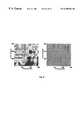
- FIG. 1is a diagrammatic illustration of an experimental setup for testing the non-linear optical imaging concepts of this invention where MC is the microscope objective; F 1 and F 2 are bandpass filters; PMT is a photomultiplier tube;
- FIG. 1 ( a )is a schematic diagram of the focal region of FIG. 1, wherein 3-dimensional scanning is accomplished by moving the objective or by moving the sample (the non-linear signals being generated mostly from the focal region);
- FIG. 1 ( b )is the graphic representation of the spectrum of non-linear signal from chicken muscle tissue excited by 100 fs laser pulses at a wavelength of 625 nm;
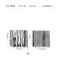
- FIG. 2 ( a )is an SHG depth image of chicken skin tissue
- FIG. 2 ( b )shows typical axially scanned profiles for the image of FIG. 2 ( a );
- FIG. 3 ( a )is an SHG depth image of fascia membrane attached to chicken muscle tissue
- FIG. 3 ( b )shows typical axially scanned profiles for the image of FIG. 3 ( a );
- FIG. 4 ( a )is an SHG depth image of chicken muscle tissue
- FIG. 4 ( b )shows typical axially scanned profiles for the image of FIG. 4 ( a );
- FIG. 5shows SHG depth profile of tryptophan powders
- FIG. 6shows 2D cross section (x-y) TPF images of chicken muscle tissue on (a) surface, and (b) 200 ⁇ m deep inside, the fibers of tissue being aligned mostly along the optical axis (z axis);
- FIG. 7are 2D images similar to FIG. 6, but wherein the fibers of tissue were aligned mostly perpendicular to the optical axis;
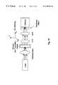
- FIG. 8is the input and detection optics arrangement for one embodiment of the invention.
- FIG. 8 ( a )is the input and detection optics arrangement for another embodiment of the invention.
- FIG. 9is the input and detection optics arrangement for yet another embodiment of the invention.
- FIG. 10is the input and detection optics arrangement for still another embodiment of the invention.
- FIG. 11is the input and detection optics arrangement for still yet another embodiment of the invention.
- FIG. 11 ( a )is the input and detection optics arrangement for a further embodiment of the invention.
- FIG. 12is a schematic diagram combining 2D tomographic maps into a 3D map of tissue sample according to this invention.
- the present inventionis based, in part, on the discovery that non-linear optical signals (harmonic generation and multi-photon excitation of fluorescence) can be used as a noninvasive in situ tomography and histology technique to generate 3-dimensional layered structure maps of symmetry and content of native fluorophors in highly scattering biological tissues.
- Such a 3-dimensional imagemay be obtained by using depth (z) and lateral (x,y) scans of a highly focused laser beam relative to the tissue sample.
- Non-linear optical signalsare measured and used to resolve symmetry and content properties of layers in biological tissues and thus to image the morphology structure of tissues.
- FIG. 1An experimental setup used to test the concept of using non-linear optical signals to construct a histology symmetry map and histology chemical components map of tissue is shown in FIG. 1 .
- the laser system usedwas an amplified CPM dye laser which generated 100 fs pulses centered at a wavelength of 625 nm. The repetition rate of the laser pulses was 6.5 kHz. The average power of laser radiation onto the sample was less than 1 mW.
- a 27X microscope objectivewas used to deliver the pump light and to collect the signal. The laser beam was focused into different depths (z) below the tissue surface by scanning the sample along the optical axis of the microscope objective with a translation stage. The focal point is scanned at different depth into the tissue as z is moved (see FIG. 1 ( a )).
- the lateral cross surface (x, y direction) scanningis performed with another translation stage.
- the backscattered signal from focal volume in the sample by the objectivewas collected by a lens into a photo-detector.
- a photomultiplier and a computer controlled lock-in amplifierwere used to detect the signal and record the data.
- Appropriate band pass filterswere inserted in the excitation and signal paths.
- the samples for demonstration of imagingwere excised frozen then thawed chicken tissues obtained from the upper thigh portion.
- FIG. 1 ( b )A typical spectrum of non-linear optical signal from chicken muscle tissue excited at 625 nm is shown in FIG. 1 ( b ). This spectrum curve was obtained by replacing the bandpass filter in front of the photo-detector with a spectrometer. The SHG signal at 312.5 nm is larger than the TPF signal from 320 to 400 nm. The TPF signal was determined to be generated from tryptophan molecules in the tissue.
- FIGS. 2 to 72-dimensional SHG tomography maps (x-z) in pseudo-color from various tissue interfaces are shown in FIGS. 2 ( a ), 3( a ) and 4( a ).
- the positive Z directionis defined as the focal plane sliced deeper into the tissue surface.
- a set of typical axially scanned profiles along the Z direction at different lateral pointsare displayed in FIGS. 2 ( b ), 3( b ), and 4( b ).
- FIG. 2 ( a )shows the imaged structure of a section of chicken skin tissue attached to a muscle tissue.
- the map in FIG. 3 ( a )shows the changes of a tendon like membrane of fascia attached to a muscle tissue. In FIG. 3 ( a ), only muscle tissue was imaged.
- the layered structure of the mediumis clearly resolved in the SHG profiles scanned in axial direction.
- the salient features of these profilesare evidenced by the observed intensity apexes along the Z direction, appearing before and after the dominate maximum.
- FIG. 2 ( b )a major peak was resolved first from the skin tissue.
- the second or the third subsidiary peaksare believed to be resolved from the sub-surface layered structures due to multiple interfaces.
- FIG. 3 ( b )a minor peak emerged first from the tendon membrane, followed by the response from the muscle.
- the corresponding image in FIG. 3 ( a )also exhibited two high intensity (red, in some cases yellow) regions with a dip band (green) in between.
- the first peakwas found to have a lower strength and narrower in space if one noticed that a dominant and broader peak appeared first from the skin tissue.
- An estimation of the membrane thicknessis in the range of a few tens of micrometers.
- FIG. 4only muscle tissue has been imaged and the differences can be seen more clearly from the individual axially scanned profiles.
- the overall signalis about one order of magnitude smaller than that from the skin tissue, thus the minor changes at the tail part are magnified due to scale differences. From this, one can conclude that the structure is not from a real histology layer, but rather from the detailed variations in the local environment, such as encountered collagen fibrils and mesentery fibers.
- SHG confocal microscopy tomographyis a method which combines high spatial resolution with scattering rejection capability and a morphology symmetry sensitivity on a microscopic level. Because the intensity of the harmonic waves are quadratic proportional to the fundamental light intensity, SHG signals are generated from the focal volume in the samples only. The scattered fundamental light, which could be widely distributed in the highly scattering sample, does not generate SHG. Furthermore, detecting SHG in confocal configuration increases collection efficiency. The SHG detected is known coming from focal volume even though SHG light can be scattered when emerging from the sample. Due to symmetry dependence, for example, ⁇ (2) is inhibited in an isotropic material. However, a broken symmetry occurs at the boundaries which enables a surface SHG contribution.
- SHGhas the additional advantage in its symmetry sensitivity. It is not only dependent on the reflectivity or the backscattering coefficient, but it is also a dependent on the ⁇ (2) tensor, which gives a response that reflects on the morphology symmetry of the ultra-structure.
- n 2 ⁇is the index of refraction
- S 2 ⁇is the backscattering coefficient at 2 ⁇ , respectively.
- ⁇is a function related to the particle size.
- SHG imageprovides additional information regarding to the tissue local symmetry as well as state.
- SHG tomographycan be used to explore the tissue histology in highly turbid medium, since most epithelial abnormalities are associated with morphological distortions, such as Frank cancer and precursors of malignancies. Tissue cells at different states have different symmetry which could lead to differentiable SHG signal strength.
- SHGmay be used to separate out different tissue states, such as cancer, pre-cancer, inflammation, benign, and normal.
- Harmonic generationarises from a coherent process where the signal highly depends on the intensity, phase, propagation direction and polarization of the incident primary wave.
- One of key concerns of various optical imaging in a turbid biomedical mediumis to extract measured data at the greatest depths while keeping the focus quality under multiple scattering events.
- the nature of the optical harmonic generationrequires a coherent excitation where the scattering length l s is the appropriate dimension to characterize the process.
- the ballistic componentcarries coherence into the medium. Its intensity depends on the scattering length as exp(-z/l s ) where z is the penetration length. Within ⁇ sub-mm of tissue surface, the coherence is still considered to be largely preserved, where the signal is also originated.
- the penetration depth into the tissue samplemay be up to several mm. This approach indicates a potential for medical diagnosis of epithelia diseases, such as cancer, pre-cancer, sunburns, burns and aging.
- FIGS. 6 and 7show tomographic images of tryptophan structure in a chicken muscle tissue sample at a fixed depth, i.e., x-y images.
- FIG. 6shows the result when tissue fibers were aligned mostly along the optical axis. The image clearly shows the round shape of individual tissue fiber.
- FIG. 7shows the image when the tissue fiber is aligned mostly perpendicular to the optical axis. The image clearly shows the line shape of fibers.
- the TPF images shown aboveare tomographic maps of tryptophan distribution in the tissue.
- multiple-photon excitation of fluorescence and harmonic generation from samplescan be detected to obtain a 3-D image of the symmetry structure and molecular chemical contents of the sample.
- Non-linear optical signals at different wavelength from spatial point on the samplecould provide more useful information, such as symmetry and molecular chemical constituents, about the sample than detecting signal from single wavelength band.
- spatial distribution of different native molecules (fluorophors)such as elastin, flavins, collagen, and NADH, can be imaged.
- Table 1summarizes the spectroscopy properties of common native fluorophors in tissue. Excitation and fluorescence wavelengths of important native fluorophors, and types of ultrashort pulse lasers to be used for non-linear optical imaging them are listed in Table 1.
- the laser sources to be usedinclude short pulse generate fundamental wavelength as well as second-harmonic waves generated from the laser.
- Nd:YAG lasergenerates picosecond duration 1064 nm fundamental light pulses as well as 532 nm SHG light pulses.
- Images of chemical makeup and symmetry properties of tissue samplecould lead to the determination of the state and histology of tissue.
- Non-linear optical imagescan be used to locate cancer, pre-cancer, and normal region in a tissue.
- the spatial resolution non-linear optical tomographyis comparable to microscopy and OCT.
- the fundamental wavelength in the infrared regionthe focus quality and depth of penetration can be further improved to circumvent multiple scattering and absorption effects.
- Non-linear optical scanning imaging techniquescan also be implemented with fiber optics and is adaptable to endoscopy for morphology evaluation inside the human and animal bodies.
- FIGS. 8 through 11Schematics of different experimental arrangements proposed to perform non-linear optical tomography are shown in FIGS. 8 through 11.
- FIG. 8shows an experimental setup with a backscattering geometry.
- the laser beamis directed to the sample by a dichroic beam splitter and a microscope objective.
- the dichroic beam splitterreflects the excitation laser light from the laser and from the sample while transmitting the SHG and TPF light generated from tissue sample.
- the MPEF and HG from the tissue samplewere collected by the same objective and transmitted through the dichroic beam splitter.
- the non-linear optical signalwas then collected by relay optics, passed through a filter selective for the desired light (i.e., HG or MPEF) and impinged on a photo-detector.
- FIG. 9shows the schematic for incorporating an optical fiber into the imaging system. Laser light is coupled into a fiber in a fiber bundle. A micro-lens at the end of bundle tip is used to focus light into the tissue sample. The non-linear optical signals are collected by other fibers in the bundle and relayed to a photo-detector. Quartz fibers are to be used to deliver the laser light to the sample and to collect non-linear optical signals. This design may be used for endoscopy applications.
- FIG. 10shows the setup for a transmission geometry.
- Laser lightis delivered to the sample by a microscope objective lens.
- the transmitted nonlinear optical signalis collected by optics and detected by a photo-detector. This design is suitable for thin samples or near-transparent samples.
- the scanningis accomplished by moving the sample.
- FIG. 11shows the experimental arrangement of using rotating optics to achieve x-y scanning. The rotation is controlled by galvanometer and/or PZT devices. The depth scan is controlled by moving the sample.
- the detector shown in these schematicsincludes components separating the non-linear optical signal from the excitation light, and components detecting the non-linear optical signals.
- the SHG and TPF images shown above for the demonstration of the principlesare 2-D images.
- the imagesare tomographic slices of the tissue sample.
- 3-D imagescan be obtained by combining these 2-D images together for better visualization.
- x-y slices at different depths z or x-z images at different lateral positions ycan be combined to form a 3-D image.
- Interested volumes in the samplecan then be easily identified.
- the nonlinear techniques shown herenot only can be used for imaging structures of interested medium, but also can be used to induce a precision local change inside the medium.
- Multi-photon absorption and induced fluorescence, as well as harmonic generation,can be used to activate dyes used in photodynamic therapy (PDT) and to induce photopolymerization for microfabrification.
- PDTphotodynamic therapy
- a tomographic histology imaging system for scattering/turbid medium and biomedical tissuescomprises:
- the light emerging therefromconsisting the fundamental (incident) light and the harmonic wave light, and fluorescence due to multi-photon excitations(MPEF),
- pulsed laser light sourceare pulsed lasers generating picosecond and femtosecond fundamental and second harmonic light pulses in 400 ⁇ 1400 nm wavelength region.
- the NIR mode-locked lasersinclude Ti:Sapphire, Cr 4+ :Forsterite, Nd:YAG, Cr:YAG, Cr 4+ :Ca 2 GeO 4 (CUNYITE), Colliding pulse mode-lock lasers, and semiconductor diode lasers.
- Laser pulses at longer wavelengthcan be used for deeper scanning into the tissue sample.
- TPF excited from 540 to 630 nm fundamental lightis mostly generated from trypotophan molecules
- TPF excited from 630 to 700 nmmostly comes from collagen, and elastin.
- said input opticscomprises a dichroic beam splitter, a microscope objective lens, and beam directing mirrors.
- the detecting opticscomprises the same microscope objective lens and relay optics to send optical signal to a detector. See FIG. 8 .
- said input opticscomprises an optical fiber bundle, a lens coupling laser source to a single fiber in the bundle.
- the optical signalis detected by other fibers of the bundle and relay to detector.
- micro-lensis to be attached to focus the beam into the sample. See FIG. 9 .
- the photo-detectorcomprises band pass filters at harmonic wave and MPEF wavelengths to reject the scattered laser light collected by the optics, and a photomultiplier, a CCD camera, or an intensified CCD camera.
- the photo-detectorcomprises a spectrograph to select harmonic wave signals and MPEF at the same time, an arrayed photodetector, a CCD camera, or an intensified CCD camera.
- the scanning system of paragraph (1)comprises a platform to mount the sample medium.
- the platformis mounted on a 3-axis translation stage.
- the sampleis scanned.
- the movement of the stagesis controlled by a PC computer.
- the scanning system of paragraph (1)comprises a platform mounting the sample, the platform being mounted on a single axis translation stage to perform depth scan by moving the focal point into the sample.
- the transverse scan (x,y scan)is accomplished by adding a rotating mirror or a beam deflector to the input optics.
- the rotationis controlled by galvanometer and/or PZT (piezoelectric) device. See FIG. 11 .
- PZTpiezoelectric
- the scanning system of paragraph (1)comprises a platform to mount the input optics.
- the platformis mounted on a translation or rotational stage to scan the input beam.
- the sample mediumis kept fixed.
- the movement of the stageis controlled by a PC computer.
- the scattering and/or turbid mediamay be, for example, human skin, human cervix and vagina, human gastrointestinal tract, human prostate and human bladder.
- TPFUse TPF to produce images to distinguish cancer, pre-cancer, benign, and normal regions of tissue.
Landscapes
- Health & Medical Sciences (AREA)
- Life Sciences & Earth Sciences (AREA)
- Biomedical Technology (AREA)
- Heart & Thoracic Surgery (AREA)
- Radiology & Medical Imaging (AREA)
- Biophysics (AREA)
- Pathology (AREA)
- Engineering & Computer Science (AREA)
- Nuclear Medicine, Radiotherapy & Molecular Imaging (AREA)
- Physics & Mathematics (AREA)
- Medical Informatics (AREA)
- Molecular Biology (AREA)
- Surgery (AREA)
- Animal Behavior & Ethology (AREA)
- General Health & Medical Sciences (AREA)
- Public Health (AREA)
- Veterinary Medicine (AREA)
- Investigating, Analyzing Materials By Fluorescence Or Luminescence (AREA)
Abstract
Description
| TABLE 1 |
| Spectroscopy properties of important common native fluorophors in tissue and laser sources |
| to be used for SHG and TPF imaging |
| NATIVE | |||
| FLUOROPHORS | |||
| IN TISSUE | |||
| (TISSUE | EXCITATION | EMISSION | |
| FINGER | WAVELENGTH | WAVELENGTH | LASER SOURCE FOR SHG |
| PRINTS) | BAND | BAND | AND |
| Trypotophan | |||
| 280 nm | 340 nm | 560˜630 nm, Dye, | |
| Forsterite(SHG) | |||
| Collagen | 340 nm | 380 nm | 680˜700 nm, Dye, Ti:Sapphire, |
| Cr:YAG(SHG) | |||
| 360 nm | 410 nm | 700˜740 nm, Dye, Ti:Sapphire, | |
| Cr:YAG(SHG), | |||
| CUNYITE(SHG), | |||
| Flavins | 450˜460 nm | 525 nm | 900˜940 nm, Dye, Ti: |
| NADH | |||
| 360 nm | 460 nm | 700˜730 nm, Ti:Sapphire, Dye, | |
| CUNYITE(SHG), Cr: YAG(SHG) | |||
| 250˜280 | 300˜350 | 500˜560 nm, Nd:YAG(SHG) | |
| 600˜700 nm | 630˜800 nm | 1200-1400 nm, CUNYITE, | |
| Forsterite | |||
Claims (37)
Priority Applications (1)
| Application Number | Priority Date | Filing Date | Title |
|---|---|---|---|
| US09/054,743US6208886B1 (en) | 1997-04-04 | 1998-04-03 | Non-linear optical tomography of turbid media |
Applications Claiming Priority (2)
| Application Number | Priority Date | Filing Date | Title |
|---|---|---|---|
| US4264597P | 1997-04-04 | 1997-04-04 | |
| US09/054,743US6208886B1 (en) | 1997-04-04 | 1998-04-03 | Non-linear optical tomography of turbid media |
Publications (1)
| Publication Number | Publication Date |
|---|---|
| US6208886B1true US6208886B1 (en) | 2001-03-27 |
Family
ID=26719480
Family Applications (1)
| Application Number | Title | Priority Date | Filing Date |
|---|---|---|---|
| US09/054,743Expired - LifetimeUS6208886B1 (en) | 1997-04-04 | 1998-04-03 | Non-linear optical tomography of turbid media |
Country Status (1)
| Country | Link |
|---|---|
| US (1) | US6208886B1 (en) |
Cited By (88)
| Publication number | Priority date | Publication date | Assignee | Title |
|---|---|---|---|---|
| US20030109787A1 (en)* | 2001-12-12 | 2003-06-12 | Michael Black | Multiple laser diagnostics |
| FR2834349A1 (en)* | 2001-12-28 | 2003-07-04 | Mauna Kea Technologies | CONFOCAL IMAGING APPARATUS ESPECIALLY FOR ENDOSCOPES |
| US20030149346A1 (en)* | 2000-03-03 | 2003-08-07 | Arnone Donald Dominic | Imaging apparatus and method |
| US6631289B2 (en)* | 2000-01-20 | 2003-10-07 | Research Foundation Of Cuny | System and method of fluorescence spectroscopic imaging for characterization and monitoring of tissue damage |
| US20040021771A1 (en)* | 2002-07-16 | 2004-02-05 | Xenogen Corporation | Method and apparatus for 3-D imaging of internal light sources |
| US20040082940A1 (en)* | 2002-10-22 | 2004-04-29 | Michael Black | Dermatological apparatus and method |
| US20040080750A1 (en)* | 2002-08-01 | 2004-04-29 | Wolf David E. | Fluorescence correlation spectroscopy instrument and method of using the same |
| US20040109636A1 (en)* | 2002-12-04 | 2004-06-10 | Jeff Korn | Optical coupler for rotating catheter |
| US20040111032A1 (en)* | 2002-12-04 | 2004-06-10 | Jeff Korn | Optical coupler for rotating catheter |
| US20040249274A1 (en)* | 2003-03-18 | 2004-12-09 | Yaroslavsky Anna N. | Polarized light imaging devices and methods |
| US6838074B2 (en) | 2001-08-08 | 2005-01-04 | Bristol-Myers Squibb Company | Simultaneous imaging of cardiac perfusion and a vitronectin receptor targeted imaging agent |
| US20050036150A1 (en)* | 2003-01-24 | 2005-02-17 | Duke University | Method for optical coherence tomography imaging with molecular contrast |
| US20050049582A1 (en)* | 2001-12-12 | 2005-03-03 | Debenedictis Leonard C. | Method and apparatus for fractional photo therapy of skin |
| US20050063041A1 (en)* | 2003-09-20 | 2005-03-24 | Chi-Kuang Sun | Harmonic generation microscopy |
| US20050171433A1 (en)* | 2004-01-08 | 2005-08-04 | Boppart Stephen A. | Multi-functional plasmon-resonant contrast agents for optical coherence tomography |
| US20050237530A1 (en)* | 2004-04-26 | 2005-10-27 | Schnittker Mark V | Imaging apparatus for small spot optical characterization |
| US20050258375A1 (en)* | 2004-01-26 | 2005-11-24 | Institut National De La Sante Et De La Recherche Medicale | Confocal laser scanning microscopy apparatus |
| WO2004052181A3 (en)* | 2002-12-11 | 2006-02-23 | Univ California | Device and method for inducing vascular injury and/or blockage in an animal model |
| US7005653B1 (en)* | 2002-06-18 | 2006-02-28 | Nanopoint, Inc. | Near-field intra-cellular apertureless tomographic imaging |
| US20060119843A1 (en)* | 2002-10-28 | 2006-06-08 | O'connell Daniel G | Cell tray |
| US20060118696A1 (en)* | 2001-11-08 | 2006-06-08 | O'connell Dan | Precision optical intracellular near field imaging/spectroscopy technology |
| US20060155266A1 (en)* | 2003-03-27 | 2006-07-13 | Dieter Manstein | Method and apparatus for dermatological treatment and fractional skin resurfacing |
| WO2006079143A1 (en)* | 2004-11-15 | 2006-08-03 | The University Of New England | Detection of cancer |
| US20060184043A1 (en)* | 2005-01-20 | 2006-08-17 | Tromberg Bruce J | Method and apparatus for high resolution spatially modulated fluorescence imaging and tomography |
| US20060192969A1 (en)* | 2005-02-28 | 2006-08-31 | Marks Daniel L | Distinguishing non-resonant four-wave-mixing noise in coherent stokes and anti-stokes Raman scattering |
| US20060241349A1 (en)* | 2002-12-12 | 2006-10-26 | Kazuhiro Gono | Imaging apparatus |
| US20060268153A1 (en)* | 2005-05-11 | 2006-11-30 | Xenogen Corporation | Surface contruction using combined photographic and structured light information |
| US20060285635A1 (en)* | 2005-04-15 | 2006-12-21 | Boppart Stephen A | Contrast enhanced spectroscopic optical coherence tomography |
| US20070016080A1 (en)* | 2005-04-28 | 2007-01-18 | Research Foundation Of The City University Of New York | Imaging systems and methods to improve backscattering imaging using circular polarization memory |
| US20070049996A1 (en)* | 2005-08-29 | 2007-03-01 | Reliant Technologies, Inc. | Monitoring Method and Apparatus for Fractional Photo-Therapy Treatment |
| US20070076199A1 (en)* | 2005-08-30 | 2007-04-05 | Nanophoton Corp. | Laser microscope |
| US20070093798A1 (en)* | 2005-08-29 | 2007-04-26 | Reliant Technologies, Inc. | Method and Apparatus for Monitoring and Controlling Thermally Induced Tissue Treatment |
| US20070128733A1 (en)* | 2002-09-27 | 2007-06-07 | Saloma Caesar A | Two-color (two-photon) excitation with focused excitation beams and a raman shifter |
| CN1326492C (en)* | 2002-04-19 | 2007-07-18 | 维森盖特有限公司 | Variable speed motion optical tomography for small targets |
| US20070253908A1 (en)* | 2002-07-16 | 2007-11-01 | Xenogen Corporation | Fluorescent light tomography |
| US7298415B2 (en) | 2001-07-13 | 2007-11-20 | Xenogen Corporation | Structured light imaging apparatus |
| US20070270697A1 (en)* | 2001-05-17 | 2007-11-22 | Xenogen Corporation | Method and apparatus for determining target depth, brightness and size within a body region |
| US20080052052A1 (en)* | 2006-08-24 | 2008-02-28 | Xenogen Corporation | Apparatus and methods for determining optical tissue properties |
| WO2007144830A3 (en)* | 2006-06-14 | 2008-03-06 | Koninkl Philips Electronics Nv | Optical fluorescence tomography calibration |
| US20080058782A1 (en)* | 2006-08-29 | 2008-03-06 | Reliant Technologies, Inc. | Method and apparatus for monitoring and controlling density of fractional tissue treatments |
| US20080161782A1 (en)* | 2006-10-26 | 2008-07-03 | Reliant Technologies, Inc. | Micropore delivery of active substances |
| US20080198355A1 (en)* | 2006-12-27 | 2008-08-21 | Cambridge Research & Instrumentation, Inc | Surface measurement of in-vivo subjects using spot projector |
| US20090012406A1 (en)* | 2007-07-03 | 2009-01-08 | Llewellyn Michael E | Method and system of using intrinsic-based photosensing with high-speed line scanning for characterization of biological thick tissue including muscle |
| US20090137994A1 (en)* | 2004-06-14 | 2009-05-28 | Rellant Technologies, Inc, | Adaptive control of optical pulses for laser medicine |
| US20090173886A1 (en)* | 2008-01-03 | 2009-07-09 | Lucent Technologies, Inc. | Cloaking device detection system |
| US20090221920A1 (en)* | 2008-01-18 | 2009-09-03 | Boppart Stephen A | Low-coherence interferometry and optical coherence tomography for image-guided surgical treatment of solid tumors |
| US20090225409A1 (en)* | 2005-04-14 | 2009-09-10 | Ilev Iiko K | Ultrahigh-Resolution Fiber-Optic Confocal Microscope and Method |
| US20090252682A1 (en)* | 2006-06-01 | 2009-10-08 | The General Hospital Corporation | In-vivo optical imaging method including analysis of dynamic images |
| DE102008020889A1 (en) | 2008-04-22 | 2009-11-05 | Nanolit Gmbh | Method and apparatus for volumetric scanning |
| US7623908B2 (en) | 2003-01-24 | 2009-11-24 | The Board Of Trustees Of The University Of Illinois | Nonlinear interferometric vibrational imaging |
| US7751057B2 (en) | 2008-01-18 | 2010-07-06 | The Board Of Trustees Of The University Of Illinois | Magnetomotive optical coherence tomography |
| WO2010090673A1 (en)* | 2009-01-20 | 2010-08-12 | The Trustees Of Dartmouth College | Method and apparatus for depth-resolved fluorescence, chromophore, and oximetry imaging for lesion identification during surgery |
| US7787129B2 (en) | 2006-01-31 | 2010-08-31 | The Board Of Trustees Of The University Of Illinois | Method and apparatus for measurement of optical properties in tissue |
| US20110075127A1 (en)* | 2009-09-30 | 2011-03-31 | Advantest Corporation | Electromagnetic wave measuring apparatus |
| US20110124988A1 (en)* | 2009-11-19 | 2011-05-26 | David Cuccia | Method and apparatus for analysis of turbid media via single-element detection using structured illumination |
| CN102095690A (en)* | 2010-12-20 | 2011-06-15 | 福建师范大学 | A non-destructive detection device for polarization imaging |
| CN101504370B (en)* | 2009-03-17 | 2011-06-15 | 福建师范大学 | Apparatus for simultaneous lossless detection of cell and extracellular matrix component |
| US8115934B2 (en) | 2008-01-18 | 2012-02-14 | The Board Of Trustees Of The University Of Illinois | Device and method for imaging the ear using optical coherence tomography |
| US20140192324A1 (en)* | 2006-06-20 | 2014-07-10 | Carl Zeiss Meditec, Inc. | Spectral domain optical coherence tomography system |
| US8892192B2 (en) | 2012-11-07 | 2014-11-18 | Modulated Imaging, Inc. | Efficient modulated imaging |
| US20150196202A1 (en)* | 2013-11-14 | 2015-07-16 | The George Washington University | Systems and Methods for Determining Lesion Depth Using Fluorescence Imaging |
| CN105286797A (en)* | 2015-11-03 | 2016-02-03 | 北京大学 | Vertical type rotary fluorescent molecular tomographic imaging system and imaging method thereof |
| CN105548099A (en)* | 2015-12-04 | 2016-05-04 | 西北大学 | Cultural relic lossless three-dimensional imaging and component identification method based on two-photon excitation fluorescence |
| US9336592B2 (en) | 2012-02-03 | 2016-05-10 | The Trustees Of Dartmouth College | Method and apparatus for determining tumor shift during surgery using a stereo-optical three-dimensional surface-mapping system |
| US20160202462A1 (en)* | 2013-08-28 | 2016-07-14 | Imagine Optic | System and method of edge-illumination microscopy |
| CN106028914A (en)* | 2013-11-14 | 2016-10-12 | 乔治华盛顿大学 | Systems and methods for determining lesion depth using fluorescence imaging |
| WO2016203409A1 (en)* | 2015-06-15 | 2016-12-22 | University Of New South Wales | Engineered materials and methods of forming |
| US9846121B2 (en) | 2009-06-17 | 2017-12-19 | W.O.M. World Of Medicine Gmbh | Device and method for multi-photon fluorescence microscopy for obtaining information from biological tissue |
| CN108590342A (en)* | 2015-10-30 | 2018-09-28 | 长园共创电力安全技术股份有限公司 | A kind of door lock having state acquisition function |
| US10261298B1 (en)* | 2014-12-09 | 2019-04-16 | The Board Of Trustees Of The Leland Stanford Junior University | Near-infrared-II confocal microscope and methods of use |
| US10517674B2 (en) | 2013-03-22 | 2019-12-31 | Koninklijke Philips N.V. | Device for non-invasive treatment of skin using laser light |
| US10568535B2 (en) | 2008-05-22 | 2020-02-25 | The Trustees Of Dartmouth College | Surgical navigation with stereovision and associated methods |
| US10682179B2 (en) | 2014-11-03 | 2020-06-16 | 460Medical, Inc. | Systems and methods for determining tissue type |
| US10716462B2 (en) | 2011-09-22 | 2020-07-21 | The George Washington University | Systems and methods for visualizing ablated tissue |
| US10722301B2 (en) | 2014-11-03 | 2020-07-28 | The George Washington University | Systems and methods for lesion assessment |
| US10736512B2 (en) | 2011-09-22 | 2020-08-11 | The George Washington University | Systems and methods for visualizing ablated tissue |
| US10779904B2 (en) | 2015-07-19 | 2020-09-22 | 460Medical, Inc. | Systems and methods for lesion formation and assessment |
| EP3847968A1 (en) | 2011-11-28 | 2021-07-14 | The Board of Trustees of the Leland Stanford Junior University | System and method useful for sarcomere imaging via objective-based microscopy |
| US11172826B2 (en) | 2016-03-08 | 2021-11-16 | Enspectra Health, Inc. | Non-invasive detection of skin disease |
| US11457817B2 (en) | 2013-11-20 | 2022-10-04 | The George Washington University | Systems and methods for hyperspectral analysis of cardiac tissue |
| US11510600B2 (en) | 2012-01-04 | 2022-11-29 | The Trustees Of Dartmouth College | Method and apparatus for quantitative and depth resolved hyperspectral fluorescence and reflectance imaging for surgical guidance |
| US11564639B2 (en) | 2013-02-13 | 2023-01-31 | The Trustees Of Dartmouth College | Method and apparatus for medical imaging using differencing of multiple fluorophores |
| US11633149B2 (en) | 2017-04-28 | 2023-04-25 | Enspectra Health, Inc. | Systems and methods for imaging and measurement of sarcomeres |
| US11730370B2 (en) | 2006-08-24 | 2023-08-22 | Xenogen Corporation | Spectral unmixing for in-vivo imaging |
| US11937951B2 (en) | 2013-02-13 | 2024-03-26 | The Trustees Of Dartmouth College | Method and apparatus for medical imaging using differencing of multiple fluorophores |
| US12076081B2 (en) | 2020-01-08 | 2024-09-03 | 460Medical, Inc. | Systems and methods for optical interrogation of ablation lesions |
| US12144667B2 (en) | 2012-01-04 | 2024-11-19 | The Trustees Of Dartmouth College | Methods for quantitative and enhanced-contrast molecular medical imaging using cross-modality correction for differing tracer kinetics |
| US12285236B2 (en) | 2018-11-13 | 2025-04-29 | Enspectra Health, Inc. | Methods and systems for generating depth profiles with improved optical resolution |
Citations (7)
| Publication number | Priority date | Publication date | Assignee | Title |
|---|---|---|---|---|
| US5034613A (en)* | 1989-11-14 | 1991-07-23 | Cornell Research Foundation, Inc. | Two-photon laser microscopy |
| US5371368A (en)* | 1992-07-23 | 1994-12-06 | Alfano; Robert R. | Ultrafast optical imaging of objects in a scattering medium |
| US5699798A (en)* | 1990-08-10 | 1997-12-23 | University Of Washington | Method for optically imaging solid tumor tissue |
| US5813987A (en)* | 1995-08-01 | 1998-09-29 | Medispectra, Inc. | Spectral volume microprobe for analysis of materials |
| US5813988A (en)* | 1995-02-03 | 1998-09-29 | Research Foundation | Time-resolved diffusion tomographic imaging in highly scattering turbid media |
| US5865754A (en)* | 1995-08-24 | 1999-02-02 | Purdue Research Foundation Office Of Technology Transfer | Fluorescence imaging system and method |
| US5999836A (en)* | 1995-06-06 | 1999-12-07 | Nelson; Robert S. | Enhanced high resolution breast imaging device and method utilizing non-ionizing radiation of narrow spectral bandwidth |
- 1998
- 1998-04-03USUS09/054,743patent/US6208886B1/ennot_activeExpired - Lifetime
Patent Citations (7)
| Publication number | Priority date | Publication date | Assignee | Title |
|---|---|---|---|---|
| US5034613A (en)* | 1989-11-14 | 1991-07-23 | Cornell Research Foundation, Inc. | Two-photon laser microscopy |
| US5699798A (en)* | 1990-08-10 | 1997-12-23 | University Of Washington | Method for optically imaging solid tumor tissue |
| US5371368A (en)* | 1992-07-23 | 1994-12-06 | Alfano; Robert R. | Ultrafast optical imaging of objects in a scattering medium |
| US5813988A (en)* | 1995-02-03 | 1998-09-29 | Research Foundation | Time-resolved diffusion tomographic imaging in highly scattering turbid media |
| US5999836A (en)* | 1995-06-06 | 1999-12-07 | Nelson; Robert S. | Enhanced high resolution breast imaging device and method utilizing non-ionizing radiation of narrow spectral bandwidth |
| US5813987A (en)* | 1995-08-01 | 1998-09-29 | Medispectra, Inc. | Spectral volume microprobe for analysis of materials |
| US5865754A (en)* | 1995-08-24 | 1999-02-02 | Purdue Research Foundation Office Of Technology Transfer | Fluorescence imaging system and method |
Non-Patent Citations (11)
Cited By (175)
| Publication number | Priority date | Publication date | Assignee | Title |
|---|---|---|---|---|
| US6631289B2 (en)* | 2000-01-20 | 2003-10-07 | Research Foundation Of Cuny | System and method of fluorescence spectroscopic imaging for characterization and monitoring of tissue damage |
| US20030149346A1 (en)* | 2000-03-03 | 2003-08-07 | Arnone Donald Dominic | Imaging apparatus and method |
| US10076261B2 (en)* | 2000-03-03 | 2018-09-18 | Teraview Limited | Imaging apparatus and method |
| US8825140B2 (en) | 2001-05-17 | 2014-09-02 | Xenogen Corporation | Imaging system |
| US20070270697A1 (en)* | 2001-05-17 | 2007-11-22 | Xenogen Corporation | Method and apparatus for determining target depth, brightness and size within a body region |
| US7764986B2 (en) | 2001-05-17 | 2010-07-27 | Xenogen Corporation | Method and apparatus for determining target depth, brightness and size within a body region |
| US20100262019A1 (en)* | 2001-05-17 | 2010-10-14 | Xenogen Corporation | Method and apparatus for determining target depth, brightness and size within a body region |
| US8180435B2 (en) | 2001-05-17 | 2012-05-15 | Xenogen Corporation | Method and apparatus for determining target depth, brightness and size within a body region |
| US7403812B2 (en) | 2001-05-17 | 2008-07-22 | Xenogen Corporation | Method and apparatus for determining target depth, brightness and size within a body region |
| US7298415B2 (en) | 2001-07-13 | 2007-11-20 | Xenogen Corporation | Structured light imaging apparatus |
| US8279334B2 (en) | 2001-07-13 | 2012-10-02 | Xenogen Corporation | Structured light imaging apparatus |
| US20080079802A1 (en)* | 2001-07-13 | 2008-04-03 | Xenogen Corporation | Structured light imaging apparatus |
| US6838074B2 (en) | 2001-08-08 | 2005-01-04 | Bristol-Myers Squibb Company | Simultaneous imaging of cardiac perfusion and a vitronectin receptor targeted imaging agent |
| US7129454B2 (en) | 2001-11-08 | 2006-10-31 | Nanopoint, Inc. | Precision optical intracellular near field imaging/spectroscopy technology |
| US20060118696A1 (en)* | 2001-11-08 | 2006-06-08 | O'connell Dan | Precision optical intracellular near field imaging/spectroscopy technology |
| US20050049582A1 (en)* | 2001-12-12 | 2005-03-03 | Debenedictis Leonard C. | Method and apparatus for fractional photo therapy of skin |
| US20030109787A1 (en)* | 2001-12-12 | 2003-06-12 | Michael Black | Multiple laser diagnostics |
| FR2834349A1 (en)* | 2001-12-28 | 2003-07-04 | Mauna Kea Technologies | CONFOCAL IMAGING APPARATUS ESPECIALLY FOR ENDOSCOPES |
| WO2003056378A1 (en)* | 2001-12-28 | 2003-07-10 | Mauna Kea Technologies | Confocal imaging equipment in particular for endoscope |
| US7285089B2 (en) | 2001-12-28 | 2007-10-23 | Mauna Kea Technologies | Confocal imaging equipment in particular for endoscope |
| US20050078924A1 (en)* | 2001-12-28 | 2005-04-14 | Bertrand Viellerobe | Confocal imaging equipment in particular for endoscope |
| CN1326492C (en)* | 2002-04-19 | 2007-07-18 | 维森盖特有限公司 | Variable speed motion optical tomography for small targets |
| US7005653B1 (en)* | 2002-06-18 | 2006-02-28 | Nanopoint, Inc. | Near-field intra-cellular apertureless tomographic imaging |
| US20100022872A1 (en)* | 2002-07-16 | 2010-01-28 | Xenogen Corporation | Method and apparatus for 3-d imaging of internal light sources |
| US20070253908A1 (en)* | 2002-07-16 | 2007-11-01 | Xenogen Corporation | Fluorescent light tomography |
| US20080031494A1 (en)* | 2002-07-16 | 2008-02-07 | Xenogen Corporation | Fluorescent light tomography |
| US20080018899A1 (en)* | 2002-07-16 | 2008-01-24 | Xenogen Corporation | Method and apparatus for 3-d imaging of internal light sources |
| US8909326B2 (en) | 2002-07-16 | 2014-12-09 | Xenogen Corporation | Method and apparatus for 3-D imaging of internal light sources |
| US7860549B2 (en) | 2002-07-16 | 2010-12-28 | Xenogen Corporation | Method and apparatus for 3-D imaging of internal light sources |
| US20040021771A1 (en)* | 2002-07-16 | 2004-02-05 | Xenogen Corporation | Method and apparatus for 3-D imaging of internal light sources |
| US7797034B2 (en) | 2002-07-16 | 2010-09-14 | Xenogen Corporation | 3-D in-vivo imaging and topography using structured light |
| US7555332B2 (en) | 2002-07-16 | 2009-06-30 | Xenogen Corporation | Fluorescent light tomography |
| US20050201614A1 (en)* | 2002-07-16 | 2005-09-15 | Xenogen Corporation | 3-D in-vivo imaging and topography using structured light |
| US20110090316A1 (en)* | 2002-07-16 | 2011-04-21 | Xenogen Corporation | Method and apparatus for 3-d imaging of internal light sources |
| US7599731B2 (en) | 2002-07-16 | 2009-10-06 | Xenogen Corporation | Fluorescent light tomography |
| US7603167B2 (en) | 2002-07-16 | 2009-10-13 | Xenogen Corporation | Method and apparatus for 3-D imaging of internal light sources |
| US7616985B2 (en) | 2002-07-16 | 2009-11-10 | Xenogen Corporation | Method and apparatus for 3-D imaging of internal light sources |
| US7268878B2 (en)* | 2002-08-01 | 2007-09-11 | Sensor Technologies Llc | Fluorescence correlation spectroscopy instrument and method of using the same |
| US20070291254A1 (en)* | 2002-08-01 | 2007-12-20 | Sensor Technologies Llc | Fluorescence correlation spectroscopy instrument and method of using the same |
| US20040080750A1 (en)* | 2002-08-01 | 2004-04-29 | Wolf David E. | Fluorescence correlation spectroscopy instrument and method of using the same |
| US8227256B2 (en)* | 2002-09-27 | 2012-07-24 | Saloma Caesar A | Two-color (two-photon) excitation with focused excitation beams and a raman shifter |
| US20070128733A1 (en)* | 2002-09-27 | 2007-06-07 | Saloma Caesar A | Two-color (two-photon) excitation with focused excitation beams and a raman shifter |
| US20040082940A1 (en)* | 2002-10-22 | 2004-04-29 | Michael Black | Dermatological apparatus and method |
| US7190449B2 (en) | 2002-10-28 | 2007-03-13 | Nanopoint, Inc. | Cell tray |
| US20060119843A1 (en)* | 2002-10-28 | 2006-06-08 | O'connell Daniel G | Cell tray |
| US20040109636A1 (en)* | 2002-12-04 | 2004-06-10 | Jeff Korn | Optical coupler for rotating catheter |
| WO2004050143A3 (en)* | 2002-12-04 | 2005-03-24 | Infraredx Inc | Optical coupler for rotating catheter |
| US20100129027A1 (en)* | 2002-12-04 | 2010-05-27 | Infraredx, Inc. | Optical Coupler for Rotating Catheter |
| US20040111032A1 (en)* | 2002-12-04 | 2004-06-10 | Jeff Korn | Optical coupler for rotating catheter |
| US7616321B2 (en)* | 2002-12-04 | 2009-11-10 | Infraredx, Inc. | Optical coupler for rotating catheter |
| US7258687B2 (en)* | 2002-12-11 | 2007-08-21 | The Regents Of The University Of California | Device and method for inducing vascular injury and/or blockage in an animal model |
| WO2004052181A3 (en)* | 2002-12-11 | 2006-02-23 | Univ California | Device and method for inducing vascular injury and/or blockage in an animal model |
| US20070299331A1 (en)* | 2002-12-11 | 2007-12-27 | Beth Friedman | Device for inducing vascular injury and/or blockage in an animal model |
| US20060142746A1 (en)* | 2002-12-11 | 2006-06-29 | Beth Friedman | Device and method for inducing vascular injury and/or blockage in an animal model |
| US20060241349A1 (en)* | 2002-12-12 | 2006-10-26 | Kazuhiro Gono | Imaging apparatus |
| US8000776B2 (en)* | 2002-12-12 | 2011-08-16 | Olympus Corporation | Imaging apparatus |
| US7075658B2 (en)* | 2003-01-24 | 2006-07-11 | Duke University | Method for optical coherence tomography imaging with molecular contrast |
| US7623908B2 (en) | 2003-01-24 | 2009-11-24 | The Board Of Trustees Of The University Of Illinois | Nonlinear interferometric vibrational imaging |
| US20050036150A1 (en)* | 2003-01-24 | 2005-02-17 | Duke University | Method for optical coherence tomography imaging with molecular contrast |
| US7627363B2 (en)* | 2003-03-18 | 2009-12-01 | The General Hospital Corporation | Polarized light imaging devices and methods |
| US20040249274A1 (en)* | 2003-03-18 | 2004-12-09 | Yaroslavsky Anna N. | Polarized light imaging devices and methods |
| US9351792B2 (en) | 2003-03-27 | 2016-05-31 | The General Hospital Corporation | Method and apparatus for dermatological treatment and fractional skin resurfacing |
| US20080021442A1 (en)* | 2003-03-27 | 2008-01-24 | The General Hospital Corporation | Method and apparatus for dermatological treatment and fractional skin resurfacing |
| US20060155266A1 (en)* | 2003-03-27 | 2006-07-13 | Dieter Manstein | Method and apparatus for dermatological treatment and fractional skin resurfacing |
| US20050063041A1 (en)* | 2003-09-20 | 2005-03-24 | Chi-Kuang Sun | Harmonic generation microscopy |
| US6922279B2 (en) | 2003-09-20 | 2005-07-26 | National Taiwan University | Harmonic generation microscopy |
| US20050171433A1 (en)* | 2004-01-08 | 2005-08-04 | Boppart Stephen A. | Multi-functional plasmon-resonant contrast agents for optical coherence tomography |
| US7610074B2 (en) | 2004-01-08 | 2009-10-27 | The Board Of Trustees Of The University Of Illinois | Multi-functional plasmon-resonant contrast agents for optical coherence tomography |
| US20050258375A1 (en)* | 2004-01-26 | 2005-11-24 | Institut National De La Sante Et De La Recherche Medicale | Confocal laser scanning microscopy apparatus |
| US20050237530A1 (en)* | 2004-04-26 | 2005-10-27 | Schnittker Mark V | Imaging apparatus for small spot optical characterization |
| US20090137994A1 (en)* | 2004-06-14 | 2009-05-28 | Rellant Technologies, Inc, | Adaptive control of optical pulses for laser medicine |
| US8291913B2 (en) | 2004-06-14 | 2012-10-23 | Reliant Technologies, Inc. | Adaptive control of optical pulses for laser medicine |
| WO2006079143A1 (en)* | 2004-11-15 | 2006-08-03 | The University Of New England | Detection of cancer |
| US20060184043A1 (en)* | 2005-01-20 | 2006-08-17 | Tromberg Bruce J | Method and apparatus for high resolution spatially modulated fluorescence imaging and tomography |
| US7729750B2 (en) | 2005-01-20 | 2010-06-01 | The Regents Of The University Of California | Method and apparatus for high resolution spatially modulated fluorescence imaging and tomography |
| WO2006078973A3 (en)* | 2005-01-20 | 2007-10-25 | Univ California | Method and apparatus for high resolution spatially modulated fluorscence imaging and tomography |
| US20060192969A1 (en)* | 2005-02-28 | 2006-08-31 | Marks Daniel L | Distinguishing non-resonant four-wave-mixing noise in coherent stokes and anti-stokes Raman scattering |
| US7586618B2 (en) | 2005-02-28 | 2009-09-08 | The Board Of Trustees Of The University Of Illinois | Distinguishing non-resonant four-wave-mixing noise in coherent stokes and anti-stokes Raman scattering |
| US20090225409A1 (en)* | 2005-04-14 | 2009-09-10 | Ilev Iiko K | Ultrahigh-Resolution Fiber-Optic Confocal Microscope and Method |
| US8456738B2 (en)* | 2005-04-14 | 2013-06-04 | The United States Of America, As Represented By The Secretary, Department Of Health And Human Services | Ultrahigh-resolution fiber-optic confocal microscope and method |
| US7725169B2 (en) | 2005-04-15 | 2010-05-25 | The Board Of Trustees Of The University Of Illinois | Contrast enhanced spectroscopic optical coherence tomography |
| US20060285635A1 (en)* | 2005-04-15 | 2006-12-21 | Boppart Stephen A | Contrast enhanced spectroscopic optical coherence tomography |
| US20070016080A1 (en)* | 2005-04-28 | 2007-01-18 | Research Foundation Of The City University Of New York | Imaging systems and methods to improve backscattering imaging using circular polarization memory |
| US7515265B2 (en) | 2005-04-28 | 2009-04-07 | Research Foundation Of The City University Of New York | Imaging systems and methods to improve backscattering imaging using circular polarization memory |
| US8044996B2 (en) | 2005-05-11 | 2011-10-25 | Xenogen Corporation | Surface construction using combined photographic and structured light information |
| US20060268153A1 (en)* | 2005-05-11 | 2006-11-30 | Xenogen Corporation | Surface contruction using combined photographic and structured light information |
| US20070093797A1 (en)* | 2005-08-29 | 2007-04-26 | Reliant Technologies, Inc. | Method and Apparatus for Monitoring and Controlling Thermally Induced Tissue Treatment |
| US20070049996A1 (en)* | 2005-08-29 | 2007-03-01 | Reliant Technologies, Inc. | Monitoring Method and Apparatus for Fractional Photo-Therapy Treatment |
| US20070093798A1 (en)* | 2005-08-29 | 2007-04-26 | Reliant Technologies, Inc. | Method and Apparatus for Monitoring and Controlling Thermally Induced Tissue Treatment |
| US7824395B2 (en) | 2005-08-29 | 2010-11-02 | Reliant Technologies, Inc. | Method and apparatus for monitoring and controlling thermally induced tissue treatment |
| US20070076199A1 (en)* | 2005-08-30 | 2007-04-05 | Nanophoton Corp. | Laser microscope |
| US7787129B2 (en) | 2006-01-31 | 2010-08-31 | The Board Of Trustees Of The University Of Illinois | Method and apparatus for measurement of optical properties in tissue |
| US20090252682A1 (en)* | 2006-06-01 | 2009-10-08 | The General Hospital Corporation | In-vivo optical imaging method including analysis of dynamic images |
| US9220411B2 (en)* | 2006-06-01 | 2015-12-29 | The General Hospital Corporation | In-vivo optical imaging method including analysis of dynamic images |
| WO2007144830A3 (en)* | 2006-06-14 | 2008-03-06 | Koninkl Philips Electronics Nv | Optical fluorescence tomography calibration |
| US20090153850A1 (en)* | 2006-06-14 | 2009-06-18 | Koninklijke Philips Electronics N.V. | Optical fluorescence tomography calibration |
| US9372067B2 (en)* | 2006-06-20 | 2016-06-21 | Carl Zeiss Meditec, Inc. | Spectral domain optical coherence tomography system |
| US20140192324A1 (en)* | 2006-06-20 | 2014-07-10 | Carl Zeiss Meditec, Inc. | Spectral domain optical coherence tomography system |
| US11730370B2 (en) | 2006-08-24 | 2023-08-22 | Xenogen Corporation | Spectral unmixing for in-vivo imaging |
| US20080052052A1 (en)* | 2006-08-24 | 2008-02-28 | Xenogen Corporation | Apparatus and methods for determining optical tissue properties |
| US10775308B2 (en) | 2006-08-24 | 2020-09-15 | Xenogen Corporation | Apparatus and methods for determining optical tissue properties |
| US20080058782A1 (en)* | 2006-08-29 | 2008-03-06 | Reliant Technologies, Inc. | Method and apparatus for monitoring and controlling density of fractional tissue treatments |
| US20080161782A1 (en)* | 2006-10-26 | 2008-07-03 | Reliant Technologies, Inc. | Micropore delivery of active substances |
| US20080198355A1 (en)* | 2006-12-27 | 2008-08-21 | Cambridge Research & Instrumentation, Inc | Surface measurement of in-vivo subjects using spot projector |
| US7990545B2 (en)* | 2006-12-27 | 2011-08-02 | Cambridge Research & Instrumentation, Inc. | Surface measurement of in-vivo subjects using spot projector |
| US8068899B2 (en)* | 2007-07-03 | 2011-11-29 | The Board Of Trustees Of The Leland Stanford Junior University | Method and system of using intrinsic-based photosensing with high-speed line scanning for characterization of biological thick tissue including muscle |
| US8897858B2 (en) | 2007-07-03 | 2014-11-25 | The Board Of Trustees Of The Leland Stanford Junior Univerity | System and method useful for sarcomere imaging via objective-based microscopy |
| US20090012406A1 (en)* | 2007-07-03 | 2009-01-08 | Llewellyn Michael E | Method and system of using intrinsic-based photosensing with high-speed line scanning for characterization of biological thick tissue including muscle |
| US10499797B2 (en) | 2007-07-03 | 2019-12-10 | The Board Of Trustees Of The Leland Stanford Junior University | System and method useful for sarcomere imaging via objective-based microscopy |
| US20090173886A1 (en)* | 2008-01-03 | 2009-07-09 | Lucent Technologies, Inc. | Cloaking device detection system |
| US7795596B2 (en)* | 2008-01-03 | 2010-09-14 | Alcatel-Lucent Usa Inc. | Cloaking device detection system |
| US7751057B2 (en) | 2008-01-18 | 2010-07-06 | The Board Of Trustees Of The University Of Illinois | Magnetomotive optical coherence tomography |
| US20090221920A1 (en)* | 2008-01-18 | 2009-09-03 | Boppart Stephen A | Low-coherence interferometry and optical coherence tomography for image-guided surgical treatment of solid tumors |
| US8115934B2 (en) | 2008-01-18 | 2012-02-14 | The Board Of Trustees Of The University Of Illinois | Device and method for imaging the ear using optical coherence tomography |
| US11779219B2 (en) | 2008-01-18 | 2023-10-10 | The Board Of Trustees Of The University Of Illinois | Low-coherence interferometry and optical coherence tomography for image-guided surgical treatment of solid tumors |
| US8983580B2 (en) | 2008-01-18 | 2015-03-17 | The Board Of Trustees Of The University Of Illinois | Low-coherence interferometry and optical coherence tomography for image-guided surgical treatment of solid tumors |
| DE102008020889A1 (en) | 2008-04-22 | 2009-11-05 | Nanolit Gmbh | Method and apparatus for volumetric scanning |
| US10568535B2 (en) | 2008-05-22 | 2020-02-25 | The Trustees Of Dartmouth College | Surgical navigation with stereovision and associated methods |
| US12114988B2 (en) | 2008-05-22 | 2024-10-15 | The Trustees Of Dartmouth College | Surgical navigation with stereovision and associated methods |
| US11129562B2 (en) | 2008-05-22 | 2021-09-28 | The Trustees Of Dartmouth College | Surgical navigation with stereovision and associated methods |
| WO2010090673A1 (en)* | 2009-01-20 | 2010-08-12 | The Trustees Of Dartmouth College | Method and apparatus for depth-resolved fluorescence, chromophore, and oximetry imaging for lesion identification during surgery |
| US8948851B2 (en) | 2009-01-20 | 2015-02-03 | The Trustees Of Dartmouth College | Method and apparatus for depth-resolved fluorescence, chromophore, and oximetry imaging for lesion identification during surgery |
| CN101504370B (en)* | 2009-03-17 | 2011-06-15 | 福建师范大学 | Apparatus for simultaneous lossless detection of cell and extracellular matrix component |
| US9846121B2 (en) | 2009-06-17 | 2017-12-19 | W.O.M. World Of Medicine Gmbh | Device and method for multi-photon fluorescence microscopy for obtaining information from biological tissue |
| US8053733B2 (en)* | 2009-09-30 | 2011-11-08 | Advantest Corporation | Electromagnetic wave measuring apparatus |
| US20110075127A1 (en)* | 2009-09-30 | 2011-03-31 | Advantest Corporation | Electromagnetic wave measuring apparatus |
| US9220412B2 (en) | 2009-11-19 | 2015-12-29 | Modulated Imaging Inc. | Method and apparatus for analysis of turbid media via single-element detection using structured illumination |
| US9277866B2 (en) | 2009-11-19 | 2016-03-08 | Modulated Imaging, Inc. | Method and apparatus for analysis of turbid media via single-element detection using structured illumination |
| US20110124988A1 (en)* | 2009-11-19 | 2011-05-26 | David Cuccia | Method and apparatus for analysis of turbid media via single-element detection using structured illumination |
| CN102095690A (en)* | 2010-12-20 | 2011-06-15 | 福建师范大学 | A non-destructive detection device for polarization imaging |
| US10716462B2 (en) | 2011-09-22 | 2020-07-21 | The George Washington University | Systems and methods for visualizing ablated tissue |
| US12075980B2 (en) | 2011-09-22 | 2024-09-03 | The George Washington University | Systems and methods for visualizing ablated tissue |
| US10736512B2 (en) | 2011-09-22 | 2020-08-11 | The George Washington University | Systems and methods for visualizing ablated tissue |
| US11559192B2 (en) | 2011-09-22 | 2023-01-24 | The George Washington University | Systems and methods for visualizing ablated tissue |
| EP3847968A1 (en) | 2011-11-28 | 2021-07-14 | The Board of Trustees of the Leland Stanford Junior University | System and method useful for sarcomere imaging via objective-based microscopy |
| US11510600B2 (en) | 2012-01-04 | 2022-11-29 | The Trustees Of Dartmouth College | Method and apparatus for quantitative and depth resolved hyperspectral fluorescence and reflectance imaging for surgical guidance |
| US11857317B2 (en) | 2012-01-04 | 2024-01-02 | The Trustees Of Dartmouth College | Method and apparatus for quantitative and depth resolved hyperspectral fluorescence and reflectance imaging for surgical guidance |
| US12144667B2 (en) | 2012-01-04 | 2024-11-19 | The Trustees Of Dartmouth College | Methods for quantitative and enhanced-contrast molecular medical imaging using cross-modality correction for differing tracer kinetics |
| US9336592B2 (en) | 2012-02-03 | 2016-05-10 | The Trustees Of Dartmouth College | Method and apparatus for determining tumor shift during surgery using a stereo-optical three-dimensional surface-mapping system |
| US9883803B2 (en) | 2012-11-07 | 2018-02-06 | Modulated Imaging, Inc. | Efficient modulated imaging |
| US10342432B2 (en) | 2012-11-07 | 2019-07-09 | Modulated Imaging, Inc. | Efficient modulated imaging |
| US8892192B2 (en) | 2012-11-07 | 2014-11-18 | Modulated Imaging, Inc. | Efficient modulated imaging |
| US11564639B2 (en) | 2013-02-13 | 2023-01-31 | The Trustees Of Dartmouth College | Method and apparatus for medical imaging using differencing of multiple fluorophores |
| US11937951B2 (en) | 2013-02-13 | 2024-03-26 | The Trustees Of Dartmouth College | Method and apparatus for medical imaging using differencing of multiple fluorophores |
| US12285277B2 (en) | 2013-02-13 | 2025-04-29 | The Trustees Of Dartmouth College | Method and apparatus for medical imaging using differencing of multiple fluorophores |
| US10517674B2 (en) | 2013-03-22 | 2019-12-31 | Koninklijke Philips N.V. | Device for non-invasive treatment of skin using laser light |
| US10031326B2 (en)* | 2013-08-28 | 2018-07-24 | Imagine Optic | System and method of edge-illumination microscopy |
| US20160202462A1 (en)* | 2013-08-28 | 2016-07-14 | Imagine Optic | System and method of edge-illumination microscopy |
| CN106028914A (en)* | 2013-11-14 | 2016-10-12 | 乔治华盛顿大学 | Systems and methods for determining lesion depth using fluorescence imaging |
| US11096584B2 (en)* | 2013-11-14 | 2021-08-24 | The George Washington University | Systems and methods for determining lesion depth using fluorescence imaging |
| US12343114B2 (en)* | 2013-11-14 | 2025-07-01 | The George Washington University | Systems and methods for determining lesion depth using fluorescence imaging |
| US20150196202A1 (en)* | 2013-11-14 | 2015-07-16 | The George Washington University | Systems and Methods for Determining Lesion Depth Using Fluorescence Imaging |
| US20220142482A1 (en)* | 2013-11-14 | 2022-05-12 | The George Washington University | Systems and Methods for Determining Lesion Depth Using Fluorescence Imaging |
| CN112674861A (en)* | 2013-11-14 | 2021-04-20 | 乔治华盛顿大学 | System and method for determining lesion depth using fluorescence imaging |
| US11457817B2 (en) | 2013-11-20 | 2022-10-04 | The George Washington University | Systems and methods for hyperspectral analysis of cardiac tissue |
| US11596472B2 (en) | 2014-11-03 | 2023-03-07 | 460Medical, Inc. | Systems and methods for assessment of contact quality |
| US10722301B2 (en) | 2014-11-03 | 2020-07-28 | The George Washington University | Systems and methods for lesion assessment |
| US11559352B2 (en) | 2014-11-03 | 2023-01-24 | The George Washington University | Systems and methods for lesion assessment |
| US10682179B2 (en) | 2014-11-03 | 2020-06-16 | 460Medical, Inc. | Systems and methods for determining tissue type |
| US10261298B1 (en)* | 2014-12-09 | 2019-04-16 | The Board Of Trustees Of The Leland Stanford Junior University | Near-infrared-II confocal microscope and methods of use |
| WO2016203409A1 (en)* | 2015-06-15 | 2016-12-22 | University Of New South Wales | Engineered materials and methods of forming |
| US11814757B2 (en) | 2015-06-15 | 2023-11-14 | Bioconix Pty Ltd. | Engineered materials and methods of forming |
| US10779904B2 (en) | 2015-07-19 | 2020-09-22 | 460Medical, Inc. | Systems and methods for lesion formation and assessment |
| US12295795B2 (en) | 2015-07-19 | 2025-05-13 | 460Medical, Inc. | Systems and methods for lesion formation and assessment |
| CN108590342B (en)* | 2015-10-30 | 2020-05-19 | 长园共创电力安全技术股份有限公司 | Door lock with state acquisition function |
| CN108590342A (en)* | 2015-10-30 | 2018-09-28 | 长园共创电力安全技术股份有限公司 | A kind of door lock having state acquisition function |
| CN105286797B (en)* | 2015-11-03 | 2018-06-08 | 北京大学 | A kind of vertical rotating fluorescent molecular tomography system and its imaging method |
| CN105286797A (en)* | 2015-11-03 | 2016-02-03 | 北京大学 | Vertical type rotary fluorescent molecular tomographic imaging system and imaging method thereof |
| CN105548099A (en)* | 2015-12-04 | 2016-05-04 | 西北大学 | Cultural relic lossless three-dimensional imaging and component identification method based on two-photon excitation fluorescence |
| CN105548099B (en)* | 2015-12-04 | 2018-07-27 | 西北大学 | The lossless three-dimensional imaging of historical relic based on two-photon fluorescence excitation and Components identification method |
| US11172826B2 (en) | 2016-03-08 | 2021-11-16 | Enspectra Health, Inc. | Non-invasive detection of skin disease |
| US11877826B2 (en) | 2016-03-08 | 2024-01-23 | Enspectra Health, Inc. | Non-invasive detection of skin disease |
| US11633149B2 (en) | 2017-04-28 | 2023-04-25 | Enspectra Health, Inc. | Systems and methods for imaging and measurement of sarcomeres |
| US12285236B2 (en) | 2018-11-13 | 2025-04-29 | Enspectra Health, Inc. | Methods and systems for generating depth profiles with improved optical resolution |
| US12076081B2 (en) | 2020-01-08 | 2024-09-03 | 460Medical, Inc. | Systems and methods for optical interrogation of ablation lesions |
Similar Documents
| Publication | Publication Date | Title |
|---|---|---|
| US6208886B1 (en) | Non-linear optical tomography of turbid media | |
| Chen et al. | Review of advanced imaging techniques | |
| US7945077B2 (en) | Hyperspectral microscope for in vivo imaging of microstructures and cells in tissues | |
| Koenig et al. | High-resolution multiphoton tomography of human skin with subcellular spatial resolution and picosecond time resolution | |
| US7623908B2 (en) | Nonlinear interferometric vibrational imaging | |
| US6879394B2 (en) | Multi-photon imaging installation | |
| Ye et al. | Nonlinear absorption microscopy | |
| CN105877711B (en) | A kind of skin disease multi-modality imaging detection system | |
| US11122978B1 (en) | PARS imaging methods | |
| US20180106729A1 (en) | Imaging platform based on nonlinear optical microscopy for rapid scanning large areas of tissue | |
| US11786128B2 (en) | PARS imaging methods | |
| EP4168775B1 (en) | Pars imaging methods | |
| Rudolph et al. | Trends in optical biomedical imaging | |
| Restall et al. | In vivo combined virtual histology and vascular imaging with dual-wavelength photoacoustic remote sensing microscopy | |
| Lai et al. | Design and test of a rigid endomicroscopic system for multimodal imaging and femtosecond laser ablation | |
| Yazdanfar et al. | Multifunctional imaging of endogenous contrast by simultaneous nonlinear and optical coherence microscopy of thick tissues | |
| Lei et al. | Label-free imaging of trabecular meshwork cells using Coherent Anti-Stokes Raman Scattering (CARS) microscopy | |
| Steven et al. | Comparison of Cornea Module and DermaInspect for noninvasive imaging of ocular surface pathologies | |
| Boppart | Optical coherence tomography: Principles applications and advances | |
| Demos et al. | Imaging of tissue microstructures using a multimodal microscope design | |
| Lin et al. | Miniaturized handheld stimulated Raman scattering microscope | |
| Weinigel et al. | Clinical multiphoton endoscopy with FLIM capability | |
| Kino et al. | Performance of dual axes confocal microscope for in vivo molecular and cellular imaging | |
| Vinegoni et al. | Multi-modality imaging of structure and function combining spectral-domain optical coherence and multiphoton microscopy | |
| Pu et al. | A commercialized Microelectromechanical Systems (MEMS)-based rapid scanning photoacoustic microscopy system with switchable optical and acoustic resolutions |
Legal Events
| Date | Code | Title | Description |
|---|---|---|---|
| AS | Assignment | Owner name:RESEARCH FOUNDATION OF CITY COLLEGE OF NEW YORK, T Free format text:ASSIGNMENT OF ASSIGNORS INTEREST;ASSIGNORS:ALFANO, ROBERT R.;GUO, YICI;LIU, FENG;AND OTHERS;REEL/FRAME:009569/0277 Effective date:19981030 | |
| FPAY | Fee payment | Year of fee payment:4 | |
| REMI | Maintenance fee reminder mailed | ||
| LAPS | Lapse for failure to pay maintenance fees | ||
| REIN | Reinstatement after maintenance fee payment confirmed | ||
| FP | Lapsed due to failure to pay maintenance fee | Effective date:20090327 | |
| FEPP | Fee payment procedure | Free format text:PETITION RELATED TO MAINTENANCE FEES FILED (ORIGINAL EVENT CODE: PMFP); ENTITY STATUS OF PATENT OWNER: SMALL ENTITY | |
| AS | Assignment | Owner name:THE RESEARCH FOUNDATION OF THE CITY UNIVERSITY OF Free format text:CORRECTIVE ASSIGNMENT TO CORRECT THE NAME OF THE ASSIGNEE PREVIOUSLY RECORDED ON REEL 009569 FRAME 0277. ASSIGNOR(S) HEREBY CONFIRMS THE THE RESEARCH FOUNDATION OF THE CITY UNIVERSITY OF NEW YORK;ASSIGNOR:ALFANO, ROBERT R;REEL/FRAME:033544/0584 Effective date:19981030 Owner name:THE RESEARCH FOUNDATION OF THE CITY UNIVERSITY OF Free format text:CORRECTIVE ASSIGNMENT TO CORRECT THE NAME OF THE ASSIGNEE PREVIOUSLY RECORDED ON REEL 009569 FRAME 0277. ASSIGNOR(S) HEREBY CONFIRMS THE ASSIGNMENT OF THE ENTIREINTEREST.;ASSIGNOR:ALFANO, ROBERT R;REEL/FRAME:033544/0584 Effective date:19981030 | |
| FPAY | Fee payment | Year of fee payment:12 Year of fee payment:8 | |
| FEPP | Fee payment procedure | Free format text:PETITION RELATED TO MAINTENANCE FEES DISMISSED (ORIGINAL EVENT CODE: PMFS); ENTITY STATUS OF PATENT OWNER: SMALL ENTITY | |
| FEPP | Fee payment procedure | Free format text:PETITION RELATED TO MAINTENANCE FEES FILED (ORIGINAL EVENT CODE: PMFP); ENTITY STATUS OF PATENT OWNER: SMALL ENTITY | |
| FEPP | Fee payment procedure | Free format text:PETITION RELATED TO MAINTENANCE FEES GRANTED (ORIGINAL EVENT CODE: PMFG); ENTITY STATUS OF PATENT OWNER: SMALL ENTITY | |
| PRDP | Patent reinstated due to the acceptance of a late maintenance fee | Effective date:20150629 | |
| STCF | Information on status: patent grant | Free format text:PATENTED CASE | |
| AS | Assignment | Owner name:ALFANO, ROBERT R., NEW YORK Free format text:ASSIGNMENT OF ASSIGNORS INTEREST;ASSIGNOR:RESEARCH FOUNDATION OF THE CITY UNIVERSITY OF NEW YORK;REEL/FRAME:037375/0176 Effective date:20151229 | |
| AS | Assignment | Owner name:ALFANO, ROBERT, NEW YORK Free format text:ASSIGNMENT OF ASSIGNORS INTEREST;ASSIGNOR:RESEARCH FOUNDATION OF THE CITY UNIVERSITY OF NEW YORK;REEL/FRAME:037488/0876 Effective date:20151229 | |
| AS | Assignment | Owner name:ALFANO OPTICAL TOMOGRAPHY LLC, NEW YORK Free format text:ASSIGNMENT OF ASSIGNORS INTEREST;ASSIGNOR:ALFANO, ROBERT R, DR.;REEL/FRAME:038853/0486 Effective date:20160609 | |
| AS | Assignment | Owner name:RESEARCH FOUNDATION OF THE CITY UNIVERSITY OF NEW Free format text:CORRECTIVE ASSIGNMENT TO CORRECT THE ASSIGNORS' PREVIOUSLY RECORDED AT REEL 033544 FRAME 0584. THE ASSIGNORS HEREBY CONFIRM THE ASSIGNMENT OF THE ENTIRE INTEREST;ASSIGNORS:ALFANO, ROBERT R;GUO, YICI;LIU, FENG;AND OTHERS;REEL/FRAME:038967/0270 Effective date:19981030 Owner name:RESEARCH FOUNDATION OF THE CITY UNIVERSITY OF NEW Free format text:ASSIGNMENT OF ASSIGNORS INTEREST;ASSIGNORS:ALFANO, ROERT R;GUO, YICI;LIU, FENG;AND OTHERS;REEL/FRAME:038966/0553 Effective date:19981030 Owner name:RESEARCH FOUNDATION OF THE CITY UNIVERSITY OF NEW Free format text:ASSIGNMENT OF ASSIGNORS INTEREST;ASSIGNORS:ALFANO, ROBERT R;GUO, YICI;LIU, FENG;AND OTHERS;REEL/FRAME:038967/0270 Effective date:19981030 Owner name:ALFANO, ROBERT R, NEW YORK Free format text:ASSIGNMENT OF ASSIGNORS INTEREST;ASSIGNOR:RESEARCH FOUNDATION OF THE CITY UNIVERSITY OF NEW YORK;REEL/FRAME:038967/0081 Effective date:20151229 Owner name:ALFANO, ROBERT R, NEW YORK Free format text:CORRECTIVE ASSIGNMENT TO CORRECT THE ASSIGNEE NAME PREVIOUSLY RECORDED AT REEL 037488 FRAME 0876. THE ASSIGNOR HEREBY CONFIRMS THE ASSIGNMENT OF THE ASSIGNORS INTEREST;ASSIGNOR:RESEARCH FOUNDATION OF THE CITY UNIVERSITY OF NEW YORK;REEL/FRAME:038967/0081 Effective date:20151229 | |
| AS | Assignment | Owner name:ALFANO OPTICAL TOMOGRAPHY LLC, NEW YORK Free format text:ASSIGNMENT OF ASSIGNORS INTEREST;ASSIGNOR:ALFANO, ROBERT R;REEL/FRAME:039741/0091 Effective date:20160901 | |
| AS | Assignment | Owner name:ALFANO OPTICAL TOMOGRAPHY LLC, NEW YORK Free format text:ASSIGNMENT OF ASSIGNORS INTEREST;ASSIGNOR:HO, PING PEI;REEL/FRAME:039839/0369 Effective date:20160907 Owner name:ALFANO OPTICAL TOMOGRAPHY LLC, NEW YORK Free format text:ASSIGNMENT OF ASSIGNORS INTEREST;ASSIGNOR:GUO, YICI;REEL/FRAME:039839/0395 Effective date:20160909 Owner name:ALFANO OPTICAL TOMOGRAPHY LLC, NEW YORK Free format text:ASSIGNMENT OF ASSIGNORS INTEREST;ASSIGNOR:LIU, FENG;REEL/FRAME:039839/0425 Effective date:20160913 |