US6208881B1 - Catheter with thin film electrodes and method for making same - Google Patents
Catheter with thin film electrodes and method for making sameDownload PDFInfo
- Publication number
- US6208881B1 US6208881B1US09/176,009US17600998AUS6208881B1US 6208881 B1US6208881 B1US 6208881B1US 17600998 AUS17600998 AUS 17600998AUS 6208881 B1US6208881 B1US 6208881B1
- Authority
- US
- United States
- Prior art keywords
- lead
- metal
- layer
- conductor
- lead body
- Prior art date
- Legal status (The legal status is an assumption and is not a legal conclusion. Google has not performed a legal analysis and makes no representation as to the accuracy of the status listed.)
- Expired - Lifetime
Links
- 238000000034methodMethods0.000titleclaimsdescription51
- 239000010409thin filmSubstances0.000titleclaimsdescription23
- 239000004020conductorSubstances0.000claimsabstractdescription55
- 229910052751metalInorganic materials0.000claimsdescription87
- 239000002184metalSubstances0.000claimsdescription87
- 239000010408filmSubstances0.000claimsdescription70
- 150000002500ionsChemical class0.000claimsdescription23
- 229910052697platinumInorganic materials0.000claimsdescription21
- 229910052737goldInorganic materials0.000claimsdescription17
- 229920000642polymerPolymers0.000claimsdescription15
- 238000000151depositionMethods0.000claimsdescription13
- 229910045601alloyInorganic materials0.000claimsdescription12
- 239000000956alloySubstances0.000claimsdescription12
- 229910052719titaniumInorganic materials0.000claimsdescription12
- 229910052759nickelInorganic materials0.000claimsdescription11
- 229910052804chromiumInorganic materials0.000claimsdescription10
- 229910052802copperInorganic materials0.000claimsdescription10
- 239000010949copperSubstances0.000claimsdescription10
- 229910052763palladiumInorganic materials0.000claimsdescription10
- 229910052709silverInorganic materials0.000claimsdescription10
- 229910052782aluminiumInorganic materials0.000claimsdescription8
- -1polyethylenePolymers0.000claimsdescription8
- 238000001816coolingMethods0.000claimsdescription7
- PXHVJJICTQNCMI-UHFFFAOYSA-NnickelSubstances[Ni]PXHVJJICTQNCMI-UHFFFAOYSA-N0.000claimsdescription7
- 229920001343polytetrafluoroethylenePolymers0.000claimsdescription7
- 239000004810polytetrafluoroethyleneSubstances0.000claimsdescription7
- 150000002739metalsChemical class0.000claimsdescription6
- 239000000203mixtureSubstances0.000claimsdescription6
- 239000010936titaniumSubstances0.000claimsdescription6
- 239000004812Fluorinated ethylene propyleneSubstances0.000claimsdescription5
- 239000004952PolyamideSubstances0.000claimsdescription5
- 239000004698PolyethyleneSubstances0.000claimsdescription5
- 239000004642PolyimideSubstances0.000claimsdescription5
- 229910002835Pt–IrInorganic materials0.000claimsdescription5
- 229920002647polyamidePolymers0.000claimsdescription5
- 229920000573polyethylenePolymers0.000claimsdescription5
- 229920001721polyimidePolymers0.000claimsdescription5
- 239000004814polyurethaneSubstances0.000claimsdescription5
- 229920002635polyurethanePolymers0.000claimsdescription5
- 229920000915polyvinyl chloridePolymers0.000claimsdescription5
- 239000004800polyvinyl chlorideSubstances0.000claimsdescription5
- 229920002379silicone rubberPolymers0.000claimsdescription5
- 239000004945silicone rubberSubstances0.000claimsdescription5
- 229910000809AlumelInorganic materials0.000claimsdescription4
- 229910001179chromelInorganic materials0.000claimsdescription4
- 239000011651chromiumSubstances0.000claimsdescription4
- 230000001747exhibiting effectEffects0.000claimsdescription4
- 230000000873masking effectEffects0.000claimsdescription4
- 229920009441perflouroethylene propylenePolymers0.000claimsdescription4
- RYGMFSIKBFXOCR-UHFFFAOYSA-NCopperChemical group[Cu]RYGMFSIKBFXOCR-UHFFFAOYSA-N0.000claimsdescription3
- 229910052786argonInorganic materials0.000claimsdescription3
- 239000012809cooling fluidSubstances0.000claimsdescription3
- 238000004519manufacturing processMethods0.000claimsdescription3
- 229910052757nitrogenInorganic materials0.000claimsdescription3
- 238000002294plasma sputter depositionMethods0.000claimsdescription3
- 238000001552radio frequency sputter depositionMethods0.000claimsdescription3
- 229910001220stainless steelInorganic materials0.000claimsdescription3
- 239000010935stainless steelSubstances0.000claimsdescription3
- 238000001704evaporationMethods0.000claims4
- 239000004813Perfluoroalkoxy alkaneSubstances0.000claims2
- VNNRSPGTAMTISX-UHFFFAOYSA-Nchromium nickelChemical group[Cr].[Ni]VNNRSPGTAMTISX-UHFFFAOYSA-N0.000claims2
- 238000005566electron beam evaporationMethods0.000claims2
- 229910052741iridiumInorganic materials0.000claims2
- 229910001120nichromeInorganic materials0.000claims2
- 229920011301perfluoro alkoxyl alkanePolymers0.000claims2
- 229920000139polyethylene terephthalatePolymers0.000claims2
- 239000005020polyethylene terephthalateSubstances0.000claims2
- 238000002207thermal evaporationMethods0.000claims2
- 238000000137annealingMethods0.000claims1
- 229910001000nickel titaniumInorganic materials0.000claims1
- 238000002560therapeutic procedureMethods0.000abstractdescription6
- 239000002131composite materialSubstances0.000abstractdescription5
- 230000000694effectsEffects0.000abstractdescription4
- 230000002411adverseEffects0.000abstract1
- 210000001519tissueAnatomy0.000description16
- 238000002679ablationMethods0.000description14
- 238000013507mappingMethods0.000description13
- BASFCYQUMIYNBI-UHFFFAOYSA-NplatinumChemical compound[Pt]BASFCYQUMIYNBI-UHFFFAOYSA-N0.000description13
- 238000000576coating methodMethods0.000description11
- 239000011248coating agentSubstances0.000description9
- 230000008021depositionEffects0.000description8
- KDLHZDBZIXYQEI-UHFFFAOYSA-NPalladiumChemical compound[Pd]KDLHZDBZIXYQEI-UHFFFAOYSA-N0.000description7
- 239000010931goldSubstances0.000description7
- 239000000463materialSubstances0.000description7
- 206010003119arrhythmiaDiseases0.000description6
- PCHJSUWPFVWCPO-UHFFFAOYSA-NgoldChemical compound[Au]PCHJSUWPFVWCPO-UHFFFAOYSA-N0.000description6
- 230000001594aberrant effectEffects0.000description5
- 238000010438heat treatmentMethods0.000description5
- 230000002262irrigationEffects0.000description5
- 238000003973irrigationMethods0.000description5
- 229920000307polymer substratePolymers0.000description5
- 239000000758substrateSubstances0.000description5
- FAPWRFPIFSIZLT-UHFFFAOYSA-MSodium chlorideChemical compound[Na+].[Cl-]FAPWRFPIFSIZLT-UHFFFAOYSA-M0.000description4
- 230000006870functionEffects0.000description4
- 238000007735ion beam assisted depositionMethods0.000description4
- 238000010884ion-beam techniqueMethods0.000description4
- 230000002107myocardial effectEffects0.000description4
- 230000008569processEffects0.000description4
- RTAQQCXQSZGOHL-UHFFFAOYSA-NTitaniumChemical compound[Ti]RTAQQCXQSZGOHL-UHFFFAOYSA-N0.000description3
- QVGXLLKOCUKJST-UHFFFAOYSA-Natomic oxygenChemical compound[O]QVGXLLKOCUKJST-UHFFFAOYSA-N0.000description3
- 230000004888barrier functionEffects0.000description3
- 210000005242cardiac chamberAnatomy0.000description3
- 238000009501film coatingMethods0.000description3
- 210000002216heartAnatomy0.000description3
- 210000005003heart tissueAnatomy0.000description3
- 230000028161membrane depolarizationEffects0.000description3
- 239000001301oxygenSubstances0.000description3
- 229910052760oxygenInorganic materials0.000description3
- 239000004332silverSubstances0.000description3
- 239000011780sodium chlorideSubstances0.000description3
- XKRFYHLGVUSROY-UHFFFAOYSA-NArgonChemical compound[Ar]XKRFYHLGVUSROY-UHFFFAOYSA-N0.000description2
- IJGRMHOSHXDMSA-UHFFFAOYSA-NAtomic nitrogenChemical compoundN#NIJGRMHOSHXDMSA-UHFFFAOYSA-N0.000description2
- 206010003662Atrial flutterDiseases0.000description2
- 241000282465CanisSpecies0.000description2
- 208000000094Chronic PainDiseases0.000description2
- 208000002193PainDiseases0.000description2
- 238000005275alloyingMethods0.000description2
- 230000006793arrhythmiaEffects0.000description2
- 210000001992atrioventricular nodeAnatomy0.000description2
- 230000000747cardiac effectEffects0.000description2
- 238000013153catheter ablationMethods0.000description2
- 230000001276controlling effectEffects0.000description2
- 238000005336crackingMethods0.000description2
- 230000006378damageEffects0.000description2
- 238000009792diffusion processMethods0.000description2
- 230000007831electrophysiologyEffects0.000description2
- 238000002001electrophysiologyMethods0.000description2
- 238000002347injectionMethods0.000description2
- 239000007924injectionSubstances0.000description2
- 239000007769metal materialSubstances0.000description2
- 230000037361pathwayEffects0.000description2
- 238000007674radiofrequency ablationMethods0.000description2
- 230000000638stimulationEffects0.000description2
- 238000004804windingMethods0.000description2
- 206010003130Arrhythmia supraventricularDiseases0.000description1
- 206010003658Atrial FibrillationDiseases0.000description1
- VYZAMTAEIAYCRO-UHFFFAOYSA-NChromiumChemical compound[Cr]VYZAMTAEIAYCRO-UHFFFAOYSA-N0.000description1
- 239000004593EpoxySubstances0.000description1
- BQCADISMDOOEFD-UHFFFAOYSA-NSilverChemical compound[Ag]BQCADISMDOOEFD-UHFFFAOYSA-N0.000description1
- 238000005299abrasionMethods0.000description1
- 230000003213activating effectEffects0.000description1
- QRRWWGNBSQSBAM-UHFFFAOYSA-Nalumane;chromiumChemical compound[AlH3].[Cr]QRRWWGNBSQSBAM-UHFFFAOYSA-N0.000description1
- XAGFODPZIPBFFR-UHFFFAOYSA-NaluminiumChemical compound[Al]XAGFODPZIPBFFR-UHFFFAOYSA-N0.000description1
- 238000013459approachMethods0.000description1
- 210000001367arteryAnatomy0.000description1
- 230000001746atrial effectEffects0.000description1
- 206010003668atrial tachycardiaDiseases0.000description1
- 239000010953base metalSubstances0.000description1
- 230000033228biological regulationEffects0.000description1
- 230000005540biological transmissionEffects0.000description1
- 230000015572biosynthetic processEffects0.000description1
- 210000004556brainAnatomy0.000description1
- 210000004375bundle of hisAnatomy0.000description1
- 230000015556catabolic processEffects0.000description1
- 239000008199coating compositionSubstances0.000description1
- 238000004891communicationMethods0.000description1
- 230000008602contractionEffects0.000description1
- 238000002788crimpingMethods0.000description1
- 239000013078crystalSubstances0.000description1
- 238000005520cutting processMethods0.000description1
- 125000004122cyclic groupChemical group0.000description1
- 230000001862defibrillatory effectEffects0.000description1
- 238000006731degradation reactionMethods0.000description1
- 230000001419dependent effectEffects0.000description1
- 238000005137deposition processMethods0.000description1
- 238000001017electron-beam sputter depositionMethods0.000description1
- 210000001174endocardiumAnatomy0.000description1
- HQQADJVZYDDRJT-UHFFFAOYSA-Nethene;prop-1-eneChemical groupC=C.CC=CHQQADJVZYDDRJT-UHFFFAOYSA-N0.000description1
- 238000002474experimental methodMethods0.000description1
- 238000011049fillingMethods0.000description1
- 239000007888film coatingSubstances0.000description1
- 229920002457flexible plasticPolymers0.000description1
- 229920005570flexible polymerPolymers0.000description1
- 239000012530fluidSubstances0.000description1
- 238000011010flushing procedureMethods0.000description1
- 239000007789gasSubstances0.000description1
- 238000000227grindingMethods0.000description1
- 210000002837heart atriumAnatomy0.000description1
- 238000007917intracranial administrationMethods0.000description1
- 238000007913intrathecal administrationMethods0.000description1
- 230000001788irregularEffects0.000description1
- 238000003698laser cuttingMethods0.000description1
- 238000010329laser etchingMethods0.000description1
- 230000003902lesionEffects0.000description1
- 238000002844meltingMethods0.000description1
- 230000008018meltingEffects0.000description1
- 238000001465metallisationMethods0.000description1
- 238000012986modificationMethods0.000description1
- 230000004048modificationEffects0.000description1
- 210000004165myocardiumAnatomy0.000description1
- 210000005036nerveAnatomy0.000description1
- 230000000926neurological effectEffects0.000description1
- 239000000615nonconductorSubstances0.000description1
- 238000013021overheatingMethods0.000description1
- 230000035515penetrationEffects0.000description1
- 239000004033plasticSubstances0.000description1
- 229920003023plasticPolymers0.000description1
- HWLDNSXPUQTBOD-UHFFFAOYSA-Nplatinum-iridium alloyChemical compound[Ir].[Pt]HWLDNSXPUQTBOD-UHFFFAOYSA-N0.000description1
- 229920003223poly(pyromellitimide-1,4-diphenyl ether)Polymers0.000description1
- 238000012545processingMethods0.000description1
- 230000001105regulatory effectEffects0.000description1
- 210000005245right atriumAnatomy0.000description1
- 231100000241scarToxicity0.000description1
- 238000007790scrapingMethods0.000description1
- 239000004065semiconductorSubstances0.000description1
- 239000010944silver (metal)Substances0.000description1
- 210000001013sinoatrial nodeAnatomy0.000description1
- 238000005476solderingMethods0.000description1
- 239000007787solidSubstances0.000description1
- 230000004936stimulating effectEffects0.000description1
- 239000000126substanceSubstances0.000description1
- 230000006794tachycardiaEffects0.000description1
- 238000012360testing methodMethods0.000description1
- 239000002470thermal conductorSubstances0.000description1
- 238000007736thin film deposition techniqueMethods0.000description1
- 230000000451tissue damageEffects0.000description1
- 231100000827tissue damageToxicity0.000description1
- 238000012546transferMethods0.000description1
- 238000001771vacuum depositionMethods0.000description1
- 238000007740vapor depositionMethods0.000description1
- 230000002792vascularEffects0.000description1
- 210000003462veinAnatomy0.000description1
Images


Classifications
- A—HUMAN NECESSITIES
- A61—MEDICAL OR VETERINARY SCIENCE; HYGIENE
- A61B—DIAGNOSIS; SURGERY; IDENTIFICATION
- A61B18/00—Surgical instruments, devices or methods for transferring non-mechanical forms of energy to or from the body
- A61B18/04—Surgical instruments, devices or methods for transferring non-mechanical forms of energy to or from the body by heating
- A61B18/12—Surgical instruments, devices or methods for transferring non-mechanical forms of energy to or from the body by heating by passing a current through the tissue to be heated, e.g. high-frequency current
- A61B18/14—Probes or electrodes therefor
- A61B18/1492—Probes or electrodes therefor having a flexible, catheter-like structure, e.g. for heart ablation
- A—HUMAN NECESSITIES
- A61—MEDICAL OR VETERINARY SCIENCE; HYGIENE
- A61B—DIAGNOSIS; SURGERY; IDENTIFICATION
- A61B5/00—Measuring for diagnostic purposes; Identification of persons
- A61B5/68—Arrangements of detecting, measuring or recording means, e.g. sensors, in relation to patient
- A61B5/6846—Arrangements of detecting, measuring or recording means, e.g. sensors, in relation to patient specially adapted to be brought in contact with an internal body part, i.e. invasive
- A61B5/6847—Arrangements of detecting, measuring or recording means, e.g. sensors, in relation to patient specially adapted to be brought in contact with an internal body part, i.e. invasive mounted on an invasive device
- A61B5/6852—Catheters
- A—HUMAN NECESSITIES
- A61—MEDICAL OR VETERINARY SCIENCE; HYGIENE
- A61B—DIAGNOSIS; SURGERY; IDENTIFICATION
- A61B5/00—Measuring for diagnostic purposes; Identification of persons
- A61B5/24—Detecting, measuring or recording bioelectric or biomagnetic signals of the body or parts thereof
- A61B5/25—Bioelectric electrodes therefor
- A61B5/279—Bioelectric electrodes therefor specially adapted for particular uses
- A61B5/28—Bioelectric electrodes therefor specially adapted for particular uses for electrocardiography [ECG]
- A61B5/283—Invasive
- A61B5/287—Holders for multiple electrodes, e.g. electrode catheters for electrophysiological study [EPS]
- A—HUMAN NECESSITIES
- A61—MEDICAL OR VETERINARY SCIENCE; HYGIENE
- A61B—DIAGNOSIS; SURGERY; IDENTIFICATION
- A61B18/00—Surgical instruments, devices or methods for transferring non-mechanical forms of energy to or from the body
- A61B2018/00005—Cooling or heating of the probe or tissue immediately surrounding the probe
- A61B2018/00011—Cooling or heating of the probe or tissue immediately surrounding the probe with fluids
- A—HUMAN NECESSITIES
- A61—MEDICAL OR VETERINARY SCIENCE; HYGIENE
- A61B—DIAGNOSIS; SURGERY; IDENTIFICATION
- A61B18/00—Surgical instruments, devices or methods for transferring non-mechanical forms of energy to or from the body
- A61B2018/00053—Mechanical features of the instrument of device
- A61B2018/00107—Coatings on the energy applicator
- A61B2018/00148—Coatings on the energy applicator with metal
- A—HUMAN NECESSITIES
- A61—MEDICAL OR VETERINARY SCIENCE; HYGIENE
- A61B—DIAGNOSIS; SURGERY; IDENTIFICATION
- A61B18/00—Surgical instruments, devices or methods for transferring non-mechanical forms of energy to or from the body
- A61B2018/00053—Mechanical features of the instrument of device
- A61B2018/0016—Energy applicators arranged in a two- or three dimensional array
- A—HUMAN NECESSITIES
- A61—MEDICAL OR VETERINARY SCIENCE; HYGIENE
- A61B—DIAGNOSIS; SURGERY; IDENTIFICATION
- A61B2562/00—Details of sensors; Constructional details of sensor housings or probes; Accessories for sensors
- A61B2562/12—Manufacturing methods specially adapted for producing sensors for in-vivo measurements
- A61B2562/125—Manufacturing methods specially adapted for producing sensors for in-vivo measurements characterised by the manufacture of electrodes
Definitions
- This inventionrelates generally to catheters used in sensing electrical activity within a patient and administering therapy, and more particularly to such catheters incorporating deposited thin film electrodes thereon for improved flexibility and trackability within the body.
- a recognized procedure used in treating various cardiac arrhythmiasinvolves ablating cardiac tissue at an appropriate site to block aberrant re-entrant paths.
- the sino-atrial node located in right atriumdepolarizes on a cyclic basis and a resulting electrical wave propagates to the AV node causing it to fire and send a further electrical wave down the bundle of His and there along the left and right bundle branches to produce a coordinated contraction of the ventricles.
- Arrhythmiaincluding atrial fibrillation, atrial flutter and tachycardia often results when the heart's normal conduction system includes a re-entrant path from the ventricles to the atrium, resulting in the feedback of electrical impulses that mix with depolarizations of the S-A node to deliver erratic signals to the A-V node.
- electrophysiology mapping and ablation electrophysiological therapyare used.
- a physicianwill first steer a catheter having sensing/ablation electrodes on the distal end thereof through the patient's vascular system and into a predetermined chamber of the heart where the treatment is to be carried out.
- the catheteris manipulated so as to place the electrodes into direct contact with the myocardial tissue that is sensed and/or to be ablated.
- Sensing and/or ablationcan be performed on the endocardial surface or via coronary veins and arteries.
- the aberrant path and/or ectopic fociis first located using a “mapping” technique in which cardiac depolarization signals picked up by the electrodes are transmitted over electrical conductors in the lead to a suitable monitor/analyzer.
- a “mapping” techniquein which cardiac depolarization signals picked up by the electrodes are transmitted over electrical conductors in the lead to a suitable monitor/analyzer.
- the physicianpositions the electrodes so that predetermined ones are in direct contact with the myocardial tissue to be ablated.
- the physicianthen activates a voltage generator, usually a source of RF voltage connected across a pair of electrodes, to effectively ablate and form a line of scar tissue interrupting the aberrant conductive pathway or to eliminate the ectopic foci.
- the electrodeseach comprise a metallic ring disposed about the circumference of the catheter body.
- a plurality of electrical conductorsextend through a lumen of the catheter body to connect the metallic rings to terminals at the proximal end of the catheter body.
- Such ring electrodesare also shown in the Truckai et al. U.S. Pat. No. 5,487,757.
- the ring electrodesare typically preformed bands of metal that are adhesively bonded, crimped or otherwise attached to the exterior surface of the catheter body, and which are connected by electrical conductors that extend through one or more lumens in the catheter body to connectors at its proximal end. These rings tend to be relatively thick and are therefor rigid.
- ring electrodesWhen it is considered that up to ten such ring electrodes are typically spaced about one centimeter apart along the distal end portion of the catheter body, they impact the ability of the distal end portion of the catheter to flex and conform to tissue structures to be mapped/ablated.
- Leads constructed in accordance with the present inventioncan find use not only in mapping the endocardium and ablating tissue to treat cardiac arrhythmias, but also can be used in fabricating pacing and defibrillating leads as well as neurologic leads placed along the spinal column by which electrical stimulation can be applied to the body for treating chronic pain.
- Such thin electrodesthey are able to readily flex and do not detract from the overall flexibility of the distal end portion of the catheter.
- theycan be configured in various shapes and patterns to optimize tissue contact.
- the present inventionprovides a method for creating a thin metallic film electrode structure for use on electrical leads that may be used for detecting electrical activity within the body of a patient and for administering therapy.
- electrically conductive thin film coatingscan comprise electrodes on mapping and/or ablation catheters or other electro-physiologic catheters without incurring the aforementioned problems and because of the thin structure of the multi-layer electrodes they readily flex without destroying the integrity of the electrode, allowing the electrodes to conform to the surface where mapping and/or ablation is to occur.
- the inventioncomprises an electrical lead having an elongated, flexible, polymer lead body with a proximal end, a distal end and supporting at least one conductor extending from the proximal end to a predetermined zone located proximate the distal end of the lead body.
- At least one electrodeis formed on the exterior surface of the lead body in that zone, the electrode being a conductive pad comprising a plurality of superimposed thin metallic film layers.
- the electrodecan be applied to the lead body in a variety of configurations, including concentric bands, elongated, linear bands, discrete spots, etc.
- the electrodemay, for example, have a composite thickness less than about 5 microns.
- Meansare provided for connecting the thin film electrode to the conductor, whereby cardiac depolarization (EKG) signals or other nerve impulses picked up by the electrodes may be conveyed to an analyzer and RF voltages for administering therapy may be applied between a pair of such electrodes on the lead body, in the case of a bipolar lead, or between an electrode on the lead and a body plate or other return electrode where a monopolar lead is being used.
- EKGcardiac depolarization
- RF voltages for administering therapymay be applied between a pair of such electrodes on the lead body, in the case of a bipolar lead, or between an electrode on the lead and a body plate or other return electrode where a monopolar lead is being used.
- the first thin metal layer on the polymer substratemay be either titanium, chromium, aluminum or nickel and the thickness of this first layer may typically be less than about 5 microns in thickness.
- the coatingis either concurrently bombarded during its deposition by high energy ions, which serve to “shot-peen” the film layer into the surface of the polymer and to continuously break up the coating from an amorphous/columnar structure to a nanocrystalline structure, exhibiting over-lapping platelet regions.
- nanocrystallinemeans that the metal layer is comprised of many, many minute plate-like structures (crystals).
- IBADion beam assisted deposition
- IBEDion beam enhanced deposition
- a second thin metal film layer or coatingis subsequently deposited over the first layer and when formed of palladium or platinum of a thickness less than 1,000 ⁇ , functions as a self-alloying/oxygen diffusion barrier layer.
- the depositionpreferably takes place in the presence of high energy ions to enhance stitching between the base layer and the second layer, again providing a desired stress-free and non-columnar structure.
- a third metal film layeris then applied to a predetermined thickness to function as a bulk conductive layer. It comprises platinum or silver or a similar conductive element or alloy and nominally lies in a range of between 500 ⁇ and 50 microns in thickness, but with 500 ⁇ to 5 microns being a preferred range. It is found that a third layer of about 2 to 3 microns in thickness is sufficient to meet the skin depths required for the RF electrical signal employed for ablation but that an upper limit of 250 microns still allows the catheter to possess a desired flexibility.
- a fourth deposited thin metal film layeris applied over the third layer to act as a biocompatible, conductive layer. While various metals may be used, gold is preferred. Gold is a soft metal exhibiting very low stress.
- the fourth layeris nominally less than 1,000 ⁇ in thickness, but may be in a range of from 500 ⁇ to 50 microns.
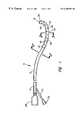
- FIG. 1is an enlarged perspective view of a mapping/ ablation lead constructed in accordance with the present invention.
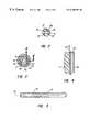
- FIG. 2is a greatly enlarged cross-sectional view taken along the line 2 — 2 in FIG. 1;
- FIG. 3is a greatly enlarged, not-to-scale, cross-sectional view taken along the line 3 — 3 in FIG. 1;
- FIG. 4is a greatly enlarged, not-to-scale, cross-sectional view taken along the line 4 — 4 in FIG. 3;
- FIG. 5is a partial view of a catheter with an elongated linear electrode on a surface thereof;
- FIG. 6is a schematic drawing of an apparatus that may be used in fabricating the multi-layer thin film electrodes of the present invention.
- FIG. 7is a greatly enlarged, partially cut-away view of a catheter body showing one technique for connecting an elongated conductor in the lead to a thin film electrode.
- the lead 10may be designed for use in cardiology for mapping a patient's cardiac chamber to locate aberrant re-entrant paths and ectopic foci and for subsequently ablating tissue in the treatment of certain cardiac arrhythmias.
- the leadcan be designed for neurologic use, such as for intracranial mapping, deep brain stimulation or placement in the intrathecal space surrounding the spinal chord for administering electrical stimulating impulses in the treatment of chronic pain.
- Other usesmay include electrical leads for use with external or implantable pulse generators and/or defibrillators.
- the catheter or lead 10includes an elongated, highly flexible polymeric lead body 12 having a proximal end 14 and a distal end 16 .
- the lead body 12may be extruded from a variety of different polymers, depending upon the particular application, such as fluorinated ethylene propylene (FEP), polyethylene, silicone rubber, polyurethane, polyamide, polyimide, polytetrafluoroethylene, and polyvinylchloride.
- FEPfluorinated ethylene propylene
- polyethylenepolyethylene
- silicone rubbersilicone rubber
- polyurethanepolyamide
- polyimidepolytetrafluoroethylene
- polyvinylchloridepolyvinylchloride
- alloys of these materials as well as blends thereofmay also be formulated in known manners to control the relative flexibility, torqueability, and pushability.
- the lead body 12may be coextruded with one or more microhelical wires as at 18 , 20 , 22 , 24 , and 26 embedded therein.
- These conductorsmay comprise multifilar conductors made of MP 35 stainless steel, platinum, platinum-iridium or copper and they extend from a proximally located electrical connector 28 to a corresponding plurality of electrodes 30 , 32 , 34 , 36 and 38 disposed in a zone proximate the distal end 16 of the catheter body 12 . While the view of FIG.
- the conductors 18 - 26 embedded in the polymer comprising the lead body 12may be fine ribbons that are affixed to and spiral along the outer surface of the lead body 12 where they make connection individually to the aforementioned electrodes.
- Suitable materials for the ribbon conductorsinclude Al, Ag, Au, Pd, Ti, Cr, Ni, Pt, Pt—Ir, Cu, alumel, chromel, constantin and alloys thereof. When surface conductors are employed, they would be covered by an insulative coating except where they join to the distal electrodes.
- the diameter of the lead bodymay be as small as from 2 to 3 French for neurological and myocardial mapping/ablation leads and up to about 8 to 12 French for other applications.
- the electrodes 30 - 38comprise a multi-layer structure of thin metal films that are sequentially deposited through an appropriate mask arrangement onto the exterior surface of the lead body.
- a first layer of metal 40is deposited directly on the lead body 12 to a thickness less than about 5 microns.
- This innermost layermay preferably be either titanium, chromium aluminum or nickel.
- the deposition of this layeris performed while the polymer substrate and the metal being deposited are bombarded with high energy ions (IBAD).
- the deposition in the presence of the bombarding ionseffectively shot peens the film into the polymer to enhance the adhesion of the inner layer 40 as it is being formed to the polymer substrate.
- the impact of the high energy ionstends to continuously break up the metal coating from an amorphous, columnar structure to a more crystalline structure exhibiting overlapping planar regions.
- An IBED processmay be used as well.
- a second layer 42is vapor deposited as high energy ions again are allowed to bombard the target area where the electrodes are being formed.
- the second layer 42 adjacent the innermost layer 40again may have a thickness between 500 ⁇ and 50 microns and preferably comprises palladium or platinum. It functions as a self-alloying oxygen diffusion barrier layer which prevents oxides from forming on the surface of the adhesion layer which would prevent prior adhesion of subsequently deposited layers and which would act as an electrical insulator.
- the high energy ionsenhance stitching between the base layer 40 and the second layer 42 while again providing a desired stressfree and non-columnar structure.
- Layer 44is substantially thicker than layers 40 and 42 so as to act as a bulk conductive layer.
- the layer 44may comprise platinum, silver, gold or copper, which are good thermal conductors.
- the third film layermay typically be from about 500 ⁇ to 250 microns in thickness.
- the metal layer 44is deposited in the same manner as the first two coatings, but in this case, the goal is to have a sufficient thickness needed to meet the skin depths required for the particular electrical signal to be employed. While lower thicknesses can be achieved to meet the needs of mapping in a cardiac chamber, or for DC transmission when RF energization is to be applied for ablation, the thicker coatings are required.
- an outer layer 46can be vapor deposited in the presence of high energy ions that are made to bombard the target area either during or subsequent to the metal deposition.
- the fourth and outer layeris deposited to act as a biocompatible and conductive layer. It can consist of a variety of metals, with gold and platinum being preferred because they are conductive, flexible, and exhibit very low internal stress when applied with this process.
- the outer layer 46may be deposited to a thickness of between 500 ⁇ and 50 microns. Where the application may require passage of the catheter several times through introducers or guide catheters, the outer coating may comprise PtIr which is generally harder and more abrasion-resistant than gold. In either event, the film needs to have high emissivity, good thermal characteristics, and conductivity properties to ensure that no thermal mismatches occur within the composite layered film electrodes.
- the preferred embodiment of the inventionmay consist of a inner film layer of titanium about 1000 ⁇ thick, a second layer of palladium about 1000 ⁇ thick, a third layer of silver about 5 microns thick, and a fourth, covering layer of gold.
- the composite filmpossesses in sufficient thickness to be above the required skin depth for the electrode which nominally is about 0.2 microns for a 500 kHz RF signal.
- the resulting electrodehas excellent adhesion to the underlying polymeric lead body and little or no internal tress so there is no cracking in the film layers as the ead body is stretched. With no cracking, problems in the rior art associated with “spark gaps” across such cracks nd resistive heating are obviated.
- FIG. 5is a partial view of a mapping/ablation lead n which is deposited a multi-layer thin metallic film lectrode 47 of the type described. It is relatively long and linear.
- a conductor 45extends through the polymer catheter body 12 for applying electrical energy to the electrode. Using this electrode configuration allows ablation over an elongated area on the surface of the myocardium without the need to drag the electrode over the myocardial tissue.
- FIG. 6schematically illustrates one apparatus whereby electrical leads, having multi-layer thin metal film electrodes, can be produced.
- Numeral 48comprises a vacuum chamber, the interior of which can be pumped down to a pressure of about 10 ⁇ 7 Torr.
- a shutter 50Disposed within the chamber is a shutter 50 that can be manipulated from outside of the chamber to expose the distal end portion of the catheter body 12 to metal evaporant 50 emanating from a boat 52 containing the metal material 54 to be deposited.
- the metal material 54may be vaporized by thermal heating of the boat 52 or by electron beam sputtering, all as is well known in the semiconductor processing arts.
- a mask, as at 56is used to define the length of and spacing between the individual film electrodes as they are being formed on the lead body.
- an ion gun 58for directing an ion beam 60 through the mask and onto the target when the shutter 50 is open.
- the ionsare produced by injecting a gas, such as argon, nitrogen or oxygen through a screen maintained at high voltage.
- a gassuch as argon, nitrogen or oxygen
- FIG. 6would also typically include biasing and focusing electrodes controlling the bombardment of the film layers during their deposition.
- a radiant heateras at 62 , may be provided as well.
- FIG. 6illustrates only one boat 52 containing a metal to be vaporized, it can be readily understood that additional boats, each with its own particular metal, may be contained within the evacuated chamber 48 and sequentially heated to vaporize its contents in forming the multiple layers comprising the electrode without having to break the vacuum.
- Vapor deposition with ion-beam bombardmentis a preferred method of forming the multilayer, thin film electrodes.
- the several metals comprising the layerscan be evaporated using any of e-beam impingement, thermal (resistive) heating, RF sputtering or plasma sputtering
- FIG. 7there is shown a greatly enlarged, partially sectioned view of the catheter body 12 showing one way in which an electrical connection can be made between the film electrode 38 and a conductor 18 .
- the catheter bodyis first prepared by cutting away a portion of the polymer comprising the catheter body to thereby expose a distal end portion 1 ′ of the conductor 18 .
- Laser cutting of the polymeris preferred, but grinding or even chemical removal of the polymeric material can be employed.
- the recess formed in the catheter body 12is then back-filled with a conductive material, such as conductive epoxy 64 , until it is again flush with the outside surface of the catheter body 12 .
- the base metal film layer 40 on electrode 38is vacuum deposited onto the lead body in the manner described above, electrical contact will be made between it and the conductive back-filling material and, thence, to the conductor 18 leading to a terminal connector 28 on the proximal end of the lead body.
- Other methods of connecting either embedded conductors or surface ribbon conductors to the thin film electrodesinclude soldering, crimping a suitable connector to both the electrode and the elongated conductor.
- a further approach for providing an interconnection between the elongated conductor and the film electrodeinvolves melting the conductor wires into the wall of the catheter body and subsequently scraping away any covering layer of plastic to thereby provide a metallic surface unto which the base film layer of the electrode can be directly applied. Once the base layer is in place, the oxide barrier layer, the conductive layer and the outer biocompatible layer can be sequentially deposited.
- FIGS. 1 and 3show the multilayer thin metal film electrodes as continuous bands or toroids
- other patternssuch as split rings, spot or strip electrodes may be used as well by providing an appropriate mask arrangement during the vacuum deposition process or by post-deposition laser etching.
- Such masking techniquesinclude the use of tape, preferably Kapton®, heat shrink tubing, metal shields, a polymeric sleeve. Irrespective of the masking technique employed, it is desirable to have electrode pads with sharp rather than tapered edges. It is found that when frequency RF energy is applied to thin film electrodes having irregular or tapered edges, non-uniform tissue burning results and there is propagation of heat along the edges of the film.
- the thin film electrodesmay range in length from about 1 mm to 10 cm, depending upon the application for which the lead/catheter is being designed. Even with a continuous band that is 10 cm in length, because the electrodes are so thin, flexibility is not sacrificed.
- such coolingcan be achieved by providing at least one lumen 66 that extends between the proximal end 14 and the distal end 16 of the catheter.
- a plurality of apertures or bores 68are formed through the wall of the tubular catheter body 12 to intersect the lumen 66 .
- the proximal connector 28also includes a flushing port 70 that is in fluid communication with the lumen 66 , allowing cooled saline solution to be injected through the Luer fitting 72 and the injection port 70 and flow through the lumen 66 to exit the catheter at the distal end portion thereof by way of the apertures 68 . In this way, the chilled saline can be made to bathe the electrodes.
- the catheter body 12may be designed to have a plurality of lumens so that cooling fluid can be injected selectively to those particular electrode pads that may require cooling.
- the saline injection ratei.e., as by activating when the electrode temperature arises above a predetermined threshold and deactivating when it falls below that threshold, one can achieve a better and deeper heat penetration profile without over-heating beneath the tissue surface.
- Temperature sensing and regulationmay be achieved by using a thermistor material, such as constantin, alumel, or chromel, that are also good conductors as the layer 44 in the multilayer film, the same conductor wire connected to the thin film electrode can be switched between a RF source for ablating and a DC source for temperature sensing.
- a thermistor devicemay be disposed within the tip of the catheter body as a discrete element rather than being incorporated into the film electrode itself.
- the sensingmay comprise a feedback loop for regulating the RF power level to a desired set point temperature, obviating the need for irrigation.
- the catheter body stock 12may be designed to have an inherent memory property whereby the distal end portion will assume a predetermined shape configuration when in a free state, i.e., without any external forces acting on same. Because of the relative thinness of the composite multilayer electrode structures, the distal end portion can be sufficiently supple to conform to tissue structures to be ablated.
- the thin film electrode of the present inventionis capable of delivering RF energy on selected substrate materials resulting in good burn depth with and without irrigation and without electrode destruction.
- tissue ablationwas effected by operating in a monopolar mode using a remote return electrode, it is contemplated that an RF voltage may be applied between a selected pair of electrodes on the lead itself in a bipolar mode.
Landscapes
- Health & Medical Sciences (AREA)
- Life Sciences & Earth Sciences (AREA)
- Surgery (AREA)
- Engineering & Computer Science (AREA)
- Public Health (AREA)
- Veterinary Medicine (AREA)
- Biomedical Technology (AREA)
- Heart & Thoracic Surgery (AREA)
- Medical Informatics (AREA)
- Molecular Biology (AREA)
- Physics & Mathematics (AREA)
- Animal Behavior & Ethology (AREA)
- General Health & Medical Sciences (AREA)
- Pathology (AREA)
- Biophysics (AREA)
- Cardiology (AREA)
- Plasma & Fusion (AREA)
- Nuclear Medicine, Radiotherapy & Molecular Imaging (AREA)
- Otolaryngology (AREA)
- Physiology (AREA)
- Materials For Medical Uses (AREA)
- Media Introduction/Drainage Providing Device (AREA)
- Electrotherapy Devices (AREA)
Abstract
Description
Claims (85)
Priority Applications (2)
| Application Number | Priority Date | Filing Date | Title |
|---|---|---|---|
| US09/176,009US6208881B1 (en) | 1998-10-20 | 1998-10-20 | Catheter with thin film electrodes and method for making same |
| US09/635,319US6400976B1 (en) | 1998-10-20 | 2000-08-09 | Catheter with thin film electrodes and method for making same |
Applications Claiming Priority (1)
| Application Number | Priority Date | Filing Date | Title |
|---|---|---|---|
| US09/176,009US6208881B1 (en) | 1998-10-20 | 1998-10-20 | Catheter with thin film electrodes and method for making same |
Related Child Applications (1)
| Application Number | Title | Priority Date | Filing Date |
|---|---|---|---|
| US09/635,319ContinuationUS6400976B1 (en) | 1998-10-20 | 2000-08-09 | Catheter with thin film electrodes and method for making same |
Publications (1)
| Publication Number | Publication Date |
|---|---|
| US6208881B1true US6208881B1 (en) | 2001-03-27 |
Family
ID=22642597
Family Applications (2)
| Application Number | Title | Priority Date | Filing Date |
|---|---|---|---|
| US09/176,009Expired - LifetimeUS6208881B1 (en) | 1998-10-20 | 1998-10-20 | Catheter with thin film electrodes and method for making same |
| US09/635,319Expired - Fee RelatedUS6400976B1 (en) | 1998-10-20 | 2000-08-09 | Catheter with thin film electrodes and method for making same |
Family Applications After (1)
| Application Number | Title | Priority Date | Filing Date |
|---|---|---|---|
| US09/635,319Expired - Fee RelatedUS6400976B1 (en) | 1998-10-20 | 2000-08-09 | Catheter with thin film electrodes and method for making same |
Country Status (1)
| Country | Link |
|---|---|
| US (2) | US6208881B1 (en) |
Cited By (160)
| Publication number | Priority date | Publication date | Assignee | Title |
|---|---|---|---|---|
| US20020038139A1 (en)* | 2000-09-26 | 2002-03-28 | Micronet Medical, Inc. | Medical lead and method for electrode attachment |
| AU751165B2 (en)* | 1998-07-15 | 2002-08-08 | Kenneth M Alo | Epidural nerve root stimulation |
| US20030093011A1 (en)* | 1998-06-17 | 2003-05-15 | Jalisi Marc Mehrzad | Performance enhancing coating on intraluminal devices |
| US6582429B2 (en)* | 2001-07-10 | 2003-06-24 | Cardiac Pacemakers, Inc. | Ablation catheter with covered electrodes allowing electrical conduction therethrough |
| US6585718B2 (en) | 2001-05-02 | 2003-07-01 | Cardiac Pacemakers, Inc. | Steerable catheter with shaft support system for resisting axial compressive loads |
| US6605086B2 (en) | 2001-05-02 | 2003-08-12 | Cardiac Pacemakers, Inc. | Steerable catheter with torque transfer system |
| US6610058B2 (en) | 2001-05-02 | 2003-08-26 | Cardiac Pacemakers, Inc. | Dual-profile steerable catheter |
| US6648875B2 (en) | 2001-05-04 | 2003-11-18 | Cardiac Pacemakers, Inc. | Means for maintaining tension on a steering tendon in a steerable catheter |
| US6652506B2 (en) | 2001-05-04 | 2003-11-25 | Cardiac Pacemakers, Inc. | Self-locking handle for steering a single or multiple-profile catheter |
| US20040024397A1 (en)* | 1999-09-17 | 2004-02-05 | Griffin Joseph C. | Ablation catheter |
| US20040133118A1 (en)* | 2002-08-21 | 2004-07-08 | New York University | Brain-machine interface systems and methods |
| US20040143258A1 (en)* | 1999-08-10 | 2004-07-22 | Biosense Webster, Inc. | Irrigation probe for ablation during open heart surgery |
| US20040210290A1 (en)* | 2003-04-08 | 2004-10-21 | Omar Omar-Pasha | Catheter |
| US20040225213A1 (en)* | 2002-01-22 | 2004-11-11 | Xingwu Wang | Magnetic resonance imaging coated assembly |
| US20040230271A1 (en)* | 2002-03-04 | 2004-11-18 | Xingwu Wang | Magnetically shielded assembly |
| US20040249428A1 (en)* | 2002-03-04 | 2004-12-09 | Xingwu Wang | Magnetically shielded assembly |
| US6846985B2 (en) | 2002-01-22 | 2005-01-25 | Nanoset, Llc | Magnetically shielded assembly |
| US20050027339A1 (en)* | 2003-07-29 | 2005-02-03 | Micronet Medical, Inc. | System and method for providing a medical lead body |
| US20050027338A1 (en)* | 2003-07-29 | 2005-02-03 | Advanced Neuromodulation Systems, Inc. | Stretchable lead body, method of manufacture, and system |
| US20050027341A1 (en)* | 2003-07-29 | 2005-02-03 | Micronet Medical, Inc. | System and method for providing a medical lead body having conductors that are wound in opposite directions |
| US20050027340A1 (en)* | 2003-07-29 | 2005-02-03 | Micronet Medical, Inc. | System and method for providing a medical lead body having dual conductor layers |
| US20050075681A1 (en)* | 2002-02-01 | 2005-04-07 | Ali Rezai | Neural stimulation delivery device with independently moveable delivery structures |
| US20050091266A1 (en)* | 2003-10-23 | 2005-04-28 | Fujitsu Limited | Data file system, data access server and data access program storage medium |
| WO2005053789A2 (en) | 2003-11-25 | 2005-06-16 | Advanced Neuromodulation Systems, Inc. | Directional stimulation lead and orientation system, and improved percutaneous-insertion needle and method of implanting a lead |
| US20050138792A1 (en)* | 1999-04-26 | 2005-06-30 | Black Damon R. | Method of forming a lead |
| WO2005089663A1 (en)* | 2004-03-05 | 2005-09-29 | Medelec-Minimeca S.A. | Saline-enhanced catheter for radiofrequency tumor ablation |
| US20050260331A1 (en)* | 2002-01-22 | 2005-11-24 | Xingwu Wang | Process for coating a substrate |
| US20060025841A1 (en)* | 2004-07-27 | 2006-02-02 | Mcintyre Cameron | Thalamic stimulation device |
| US7039470B1 (en) | 2000-09-26 | 2006-05-02 | Micronet Medical, Inc. | Medical lead and method for medical lead manufacture |
| US7047082B1 (en)* | 1999-09-16 | 2006-05-16 | Micronet Medical, Inc. | Neurostimulating lead |
| US20060122681A1 (en)* | 2004-12-06 | 2006-06-08 | Kroll Mark W | Automatic capture pacing lead |
| US20060265037A1 (en)* | 2001-11-13 | 2006-11-23 | Kuzma Janusz A | Construction of cylindrical multicontact electrode lead for neural stimulation and method of making same |
| US7149585B2 (en) | 2001-03-30 | 2006-12-12 | Micronet Medical, Inc. | Lead body and method of lead body construction |
| US20060282014A1 (en)* | 2005-06-14 | 2006-12-14 | The Regents Of The University Of Michigan | Flexible polymer microelectrode with fluid delivery capability and methods for making same |
| US7156868B1 (en)* | 1999-08-26 | 2007-01-02 | Omega Critical Care Limited | Heat transfer devices |
| US20070092989A1 (en)* | 2005-08-04 | 2007-04-26 | Micron Technology, Inc. | Conductive nanoparticles |
| US20070112402A1 (en)* | 2005-10-19 | 2007-05-17 | Duke University | Electrode systems and related methods for providing therapeutic differential tissue stimulation |
| US20070282411A1 (en)* | 2006-03-31 | 2007-12-06 | Brian Franz | Compliant electrical stimulation leads and methods of fabrication |
| WO2008051122A1 (en) | 2006-10-25 | 2008-05-02 | St. Jude Medical Ab | A medical implantable lead |
| US20080161743A1 (en)* | 2006-12-28 | 2008-07-03 | Crowe John E | Ablation device having a piezoelectric pump |
| US20080296650A1 (en)* | 2007-06-04 | 2008-12-04 | Micron Technology, Inc. | High-k dielectrics with gold nano-particles |
| US20090012578A1 (en)* | 2006-02-02 | 2009-01-08 | Vygon | Neurostimulation Catheter |
| US20090012591A1 (en)* | 2007-07-05 | 2009-01-08 | Advanced Bionics Corporation | Lead with contacts formed by coiled conductor and methods of manufacture and use |
| US20090062896A1 (en)* | 2007-08-29 | 2009-03-05 | Overstreet Edward H | Minimizing Trauma During and After Insertion of a Cochlear Lead |
| US20090149933A1 (en)* | 2007-12-06 | 2009-06-11 | Cardiac Pacemakers, Inc. | Implantable lead having a variable coil conductor pitch |
| US7555349B2 (en) | 2000-09-26 | 2009-06-30 | Advanced Neuromodulation Systems, Inc. | Lead body and method of lead body construction |
| US20090173991A1 (en)* | 2005-08-04 | 2009-07-09 | Marsh Eugene P | Methods for forming rhodium-based charge traps and apparatus including rhodium-based charge traps |
| US7560793B2 (en) | 2002-05-02 | 2009-07-14 | Micron Technology, Inc. | Atomic layer deposition and conversion |
| US20090192503A1 (en)* | 2008-01-24 | 2009-07-30 | Haim Epshtein | Device, apparatus, and method of adipose tissue treatment |
| US20090198314A1 (en)* | 2008-02-06 | 2009-08-06 | Foster Arthur J | Lead with mri compatible design features |
| US20090240249A1 (en)* | 2004-11-08 | 2009-09-24 | Cardima, Inc. | System and Method for Performing Ablation and Other Medical Procedures Using An Electrode Array with Flexible Circuit |
| US20090292237A1 (en)* | 2007-08-29 | 2009-11-26 | Advanced Bionics, Llc | Modular Drug Delivery System for Minimizing Trauma During and After Insertion of a Cochlear Lead |
| US20100004536A1 (en)* | 2008-07-03 | 2010-01-07 | Avner Rosenberg | Method and apparatus for ultrasound tissue treatment |
| US20100016761A1 (en)* | 2008-07-16 | 2010-01-21 | Avner Rosenberg | Applicator for skin treatement with automatic regulation of skin protrusion magnitude |
| US20100016985A1 (en)* | 2008-07-18 | 2010-01-21 | North Carolina State University | Processing of biocompatible coating on polymeric implants |
| US7670646B2 (en) | 2002-05-02 | 2010-03-02 | Micron Technology, Inc. | Methods for atomic-layer deposition |
| WO2010051328A1 (en)* | 2008-10-31 | 2010-05-06 | Medtronic, Inc. | Shielded conductor filar - stimulation leads |
| US20100198134A1 (en)* | 2008-01-17 | 2010-08-05 | Shimon Eckhouse | Hair removal apparatus for personal use and the method of using same |
| US20100234929A1 (en)* | 2009-03-12 | 2010-09-16 | Torsten Scheuermann | Thin profile conductor assembly for medical device leads |
| US7894915B1 (en)* | 2006-10-27 | 2011-02-22 | Pacesetter, Inc. | Implantable medical device |
| US7899537B1 (en) | 2006-10-27 | 2011-03-01 | Pacesetter, Inc. | Pericardial cardioverter defibrillator |
| US20110087299A1 (en)* | 2009-10-08 | 2011-04-14 | Masoud Ameri | Medical device lead including a flared conductive coil |
| US7927948B2 (en) | 2005-07-20 | 2011-04-19 | Micron Technology, Inc. | Devices with nanocrystals and methods of formation |
| US7949412B1 (en) | 2005-06-02 | 2011-05-24 | Advanced Bionics, Llc | Coated electrode array having uncoated electrode contacts |
| US7957818B2 (en) | 2008-06-26 | 2011-06-07 | Greatbatch Ltd. | Stimulation lead design and method of manufacture |
| US20110160829A1 (en)* | 2009-12-31 | 2011-06-30 | Foster Arthur J | Mri conditionally safe lead with multi-layer conductor |
| US20110160828A1 (en)* | 2009-12-31 | 2011-06-30 | Foster Arthur J | Mri conditionally safe lead with low-profile multi-layer conductor for longitudinal expansion |
| US20110160818A1 (en)* | 2009-12-30 | 2011-06-30 | Roger Struve | Mri-conditionally safe medical device lead |
| US20110166559A1 (en)* | 2008-09-21 | 2011-07-07 | Shimon Eckhouse | Method and apparatus for personal skin treatment |
| US7986999B2 (en) | 2006-11-30 | 2011-07-26 | Cardiac Pacemakers, Inc. | RF rejecting lead |
| US8103360B2 (en) | 2008-05-09 | 2012-01-24 | Foster Arthur J | Medical lead coil conductor with spacer element |
| US20120022504A1 (en)* | 2008-09-11 | 2012-01-26 | Syneron Medical Ltd. | Device, apparatus, and method of adipose tissue treatment |
| US20120022512A1 (en)* | 2008-01-24 | 2012-01-26 | Boris Vaynberg | Device, apparatus, and method of adipose tissue treatment |
| US20120198694A1 (en)* | 2009-09-30 | 2012-08-09 | John Swanson | Medical leads with segmented electrodes and methods of fabrication thereof |
| US20120277737A1 (en)* | 2011-04-12 | 2012-11-01 | Thermedical, Inc. | Devices and methods for remote temperature monitoring in fluid enhanced ablation therapy |
| US8332050B2 (en) | 2009-06-26 | 2012-12-11 | Cardiac Pacemakers, Inc. | Medical device lead including a unifilar coil with improved torque transmission capacity and reduced MRI heating |
| US20130204318A1 (en)* | 2012-02-08 | 2013-08-08 | Sapiens Steering Brain Stimulation B.V. | Thin Film for a Lead for Brain Applications |
| EP2626110A1 (en)* | 2012-02-08 | 2013-08-14 | Sapiens Steering Brain Stimulation B.V. | A thin film for a lead for brain applications |
| US8666512B2 (en) | 2011-11-04 | 2014-03-04 | Cardiac Pacemakers, Inc. | Implantable medical device lead including inner coil reverse-wound relative to shocking coil |
| US8712542B2 (en) | 2008-11-04 | 2014-04-29 | Boston Scientific Neuromodulation Corporation | Deposited conductive layers for leads of implantable electric stimulation systems and methods of making and using |
| US20140187874A1 (en)* | 2012-12-31 | 2014-07-03 | Volcano Corporation | Intravascular Devices, Systems, and Methods |
| US8825179B2 (en) | 2012-04-20 | 2014-09-02 | Cardiac Pacemakers, Inc. | Implantable medical device lead including a unifilar coiled cable |
| US8825181B2 (en) | 2010-08-30 | 2014-09-02 | Cardiac Pacemakers, Inc. | Lead conductor with pitch and torque control for MRI conditionally safe use |
| US8954168B2 (en) | 2012-06-01 | 2015-02-10 | Cardiac Pacemakers, Inc. | Implantable device lead including a distal electrode assembly with a coiled component |
| US8958889B2 (en) | 2012-08-31 | 2015-02-17 | Cardiac Pacemakers, Inc. | MRI compatible lead coil |
| US8983623B2 (en) | 2012-10-18 | 2015-03-17 | Cardiac Pacemakers, Inc. | Inductive element for providing MRI compatibility in an implantable medical device lead |
| US9033972B2 (en) | 2013-03-15 | 2015-05-19 | Thermedical, Inc. | Methods and devices for fluid enhanced microwave ablation therapy |
| WO2015065966A3 (en)* | 2013-10-28 | 2015-07-16 | St. Jude Medical, Cardiology Division, Inc. | Ablation catheter designs and methods with enhanced diagnostic capabilities |
| US9211240B2 (en) | 2012-02-10 | 2015-12-15 | Periproducts Ltd | Multicomponent oral care composition |
| US9254380B2 (en) | 2009-10-19 | 2016-02-09 | Cardiac Pacemakers, Inc. | MRI compatible tachycardia lead |
| US9501829B2 (en) | 2011-03-29 | 2016-11-22 | Boston Scientific Neuromodulation Corporation | System and method for atlas registration |
| US9504821B2 (en) | 2014-02-26 | 2016-11-29 | Cardiac Pacemakers, Inc. | Construction of an MRI-safe tachycardia lead |
| US9526902B2 (en) | 2008-05-15 | 2016-12-27 | Boston Scientific Neuromodulation Corporation | VOA generation system and method using a fiber specific analysis |
| US9545510B2 (en) | 2008-02-12 | 2017-01-17 | Intelect Medical, Inc. | Directional lead assembly with electrode anchoring prongs |
| US9561380B2 (en) | 2012-08-28 | 2017-02-07 | Boston Scientific Neuromodulation Corporation | Point-and-click programming for deep brain stimulation using real-time monopolar review trendlines |
| US9592389B2 (en) | 2011-05-27 | 2017-03-14 | Boston Scientific Neuromodulation Corporation | Visualization of relevant stimulation leadwire electrodes relative to selected stimulation information |
| US9604067B2 (en) | 2012-08-04 | 2017-03-28 | Boston Scientific Neuromodulation Corporation | Techniques and methods for storing and transferring registration, atlas, and lead information between medical devices |
| US9610396B2 (en) | 2013-03-15 | 2017-04-04 | Thermedical, Inc. | Systems and methods for visualizing fluid enhanced ablation therapy |
| US9743984B1 (en) | 2016-08-11 | 2017-08-29 | Thermedical, Inc. | Devices and methods for delivering fluid to tissue during ablation therapy |
| US9760688B2 (en) | 2004-07-07 | 2017-09-12 | Cleveland Clinic Foundation | Method and device for displaying predicted volume of influence |
| US20170273738A1 (en)* | 2016-03-23 | 2017-09-28 | Biosense Webster (Israel) Ltd. | Dispersed irrigation configuration for catheter tip design |
| US9776003B2 (en) | 2009-12-02 | 2017-10-03 | The Cleveland Clinic Foundation | Reversing cognitive-motor impairments in patients having a neuro-degenerative disease using a computational modeling approach to deep brain stimulation programming |
| US9792412B2 (en) | 2012-11-01 | 2017-10-17 | Boston Scientific Neuromodulation Corporation | Systems and methods for VOA model generation and use |
| US20180008821A1 (en)* | 2016-07-05 | 2018-01-11 | Pacesetter, Inc. | Implantable thin film devices |
| US9867989B2 (en) | 2010-06-14 | 2018-01-16 | Boston Scientific Neuromodulation Corporation | Programming interface for spinal cord neuromodulation |
| US9925382B2 (en) | 2011-08-09 | 2018-03-27 | Boston Scientific Neuromodulation Corporation | Systems and methods for stimulation-related volume analysis, creation, and sharing |
| US9959388B2 (en) | 2014-07-24 | 2018-05-01 | Boston Scientific Neuromodulation Corporation | Systems, devices, and methods for providing electrical stimulation therapy feedback |
| US9956419B2 (en) | 2015-05-26 | 2018-05-01 | Boston Scientific Neuromodulation Corporation | Systems and methods for analyzing electrical stimulation and selecting or manipulating volumes of activation |
| US9974959B2 (en) | 2014-10-07 | 2018-05-22 | Boston Scientific Neuromodulation Corporation | Systems, devices, and methods for electrical stimulation using feedback to adjust stimulation parameters |
| US10022176B2 (en) | 2012-08-15 | 2018-07-17 | Thermedical, Inc. | Low profile fluid enhanced ablation therapy devices and methods |
| WO2018137044A1 (en)* | 2017-01-27 | 2018-08-02 | Medtronic Cryocath Lp | Highly flexible mapping and treatment device |
| US10071249B2 (en) | 2015-10-09 | 2018-09-11 | Boston Scientific Neuromodulation Corporation | System and methods for clinical effects mapping for directional stimulation leads |
| US10195429B1 (en) | 2017-08-02 | 2019-02-05 | Lungpacer Medical Inc. | Systems and methods for intravascular catheter positioning and/or nerve stimulation |
| US10265528B2 (en) | 2014-07-30 | 2019-04-23 | Boston Scientific Neuromodulation Corporation | Systems and methods for electrical stimulation-related patient population volume analysis and use |
| US10272247B2 (en) | 2014-07-30 | 2019-04-30 | Boston Scientific Neuromodulation Corporation | Systems and methods for stimulation-related volume analysis, creation, and sharing with integrated surgical planning and stimulation programming |
| US10293164B2 (en) | 2017-05-26 | 2019-05-21 | Lungpacer Medical Inc. | Apparatus and methods for assisted breathing by transvascular nerve stimulation |
| US10350404B2 (en) | 2016-09-02 | 2019-07-16 | Boston Scientific Neuromodulation Corporation | Systems and methods for visualizing and directing stimulation of neural elements |
| US10360511B2 (en) | 2005-11-28 | 2019-07-23 | The Cleveland Clinic Foundation | System and method to estimate region of tissue activation |
| US10391314B2 (en) | 2014-01-21 | 2019-08-27 | Lungpacer Medical Inc. | Systems and related methods for optimization of multi-electrode nerve pacing |
| US10406351B2 (en) | 2013-05-01 | 2019-09-10 | Sherwin Hua | Methods and systems for intraventricular brain stimulation |
| US10406367B2 (en) | 2012-06-21 | 2019-09-10 | Lungpacer Medical Inc. | Transvascular diaphragm pacing system and methods of use |
| US10434302B2 (en) | 2008-02-11 | 2019-10-08 | Intelect Medical, Inc. | Directional electrode devices with locating features |
| US10441800B2 (en) | 2015-06-29 | 2019-10-15 | Boston Scientific Neuromodulation Corporation | Systems and methods for selecting stimulation parameters by targeting and steering |
| US10456576B2 (en) | 2010-05-10 | 2019-10-29 | St. Jude Medical Luxembourg Holdings SMI S. A. R. L (“SJM LUX SMI”) | Methods, systems and devices for reducing migration |
| US10507321B2 (en) | 2014-11-25 | 2019-12-17 | Medtronic Bakken Research Center B.V. | Multilayer structure and method of manufacturing a multilayer structure |
| US20190381274A1 (en)* | 2017-01-19 | 2019-12-19 | St. Jude Medical, Cardiology Division, Inc. | Sheath visualization |
| US10512772B2 (en) | 2012-03-05 | 2019-12-24 | Lungpacer Medical Inc. | Transvascular nerve stimulation apparatus and methods |
| US10561843B2 (en) | 2007-01-29 | 2020-02-18 | Lungpacer Medical, Inc. | Transvascular nerve stimulation apparatus and methods |
| US10589104B2 (en) | 2017-01-10 | 2020-03-17 | Boston Scientific Neuromodulation Corporation | Systems and methods for creating stimulation programs based on user-defined areas or volumes |
| US10603498B2 (en) | 2016-10-14 | 2020-03-31 | Boston Scientific Neuromodulation Corporation | Systems and methods for closed-loop determination of stimulation parameter settings for an electrical simulation system |
| US10625082B2 (en) | 2017-03-15 | 2020-04-21 | Boston Scientific Neuromodulation Corporation | Visualization of deep brain stimulation efficacy |
| US10716942B2 (en) | 2016-04-25 | 2020-07-21 | Boston Scientific Neuromodulation Corporation | System and methods for directional steering of electrical stimulation |
| US10716505B2 (en) | 2017-07-14 | 2020-07-21 | Boston Scientific Neuromodulation Corporation | Systems and methods for estimating clinical effects of electrical stimulation |
| US10776456B2 (en) | 2016-06-24 | 2020-09-15 | Boston Scientific Neuromodulation Corporation | Systems and methods for visual analytics of clinical effects |
| US10780282B2 (en) | 2016-09-20 | 2020-09-22 | Boston Scientific Neuromodulation Corporation | Systems and methods for steering electrical stimulation of patient tissue and determining stimulation parameters |
| US10780283B2 (en) | 2015-05-26 | 2020-09-22 | Boston Scientific Neuromodulation Corporation | Systems and methods for analyzing electrical stimulation and selecting or manipulating volumes of activation |
| US10792501B2 (en) | 2017-01-03 | 2020-10-06 | Boston Scientific Neuromodulation Corporation | Systems and methods for selecting MRI-compatible stimulation parameters |
| US10940308B2 (en) | 2017-08-04 | 2021-03-09 | Lungpacer Medical Inc. | Systems and methods for trans-esophageal sympathetic ganglion recruitment |
| US20210077175A1 (en)* | 2019-09-13 | 2021-03-18 | Hemostatix Medical Technologies, LLC | Hemostatic Surgical Blade, System and Method of Blade Manufacture and Method of Use |
| US10960214B2 (en) | 2017-08-15 | 2021-03-30 | Boston Scientific Neuromodulation Corporation | Systems and methods for controlling electrical stimulation using multiple stimulation fields |
| US10987511B2 (en) | 2018-11-08 | 2021-04-27 | Lungpacer Medical Inc. | Stimulation systems and related user interfaces |
| US11083871B2 (en) | 2018-05-03 | 2021-08-10 | Thermedical, Inc. | Selectively deployable catheter ablation devices |
| US11160981B2 (en) | 2015-06-29 | 2021-11-02 | Boston Scientific Neuromodulation Corporation | Systems and methods for selecting stimulation parameters based on stimulation target region, effects, or side effects |
| US11246658B2 (en) | 2016-10-04 | 2022-02-15 | St. Jude Medical, Cardiology Division, Inc. | Ablation catheter tip |
| CN114191068A (en)* | 2020-09-18 | 2022-03-18 | Tau-Pnu医疗有限公司 | Atrial fibrillation treatment catheter and atrial fibrillation treatment method using the same |
| US11285329B2 (en) | 2018-04-27 | 2022-03-29 | Boston Scientific Neuromodulation Corporation | Systems and methods for visualizing and programming electrical stimulation |
| US11298553B2 (en) | 2018-04-27 | 2022-04-12 | Boston Scientific Neuromodulation Corporation | Multi-mode electrical stimulation systems and methods of making and using |
| US11350986B2 (en) | 2015-03-31 | 2022-06-07 | St. Jude Medical, Cardiology Division, Inc. | High-thermal-sensitivity ablation catheters and catheter tips |
| US11357986B2 (en) | 2017-04-03 | 2022-06-14 | Boston Scientific Neuromodulation Corporation | Systems and methods for estimating a volume of activation using a compressed database of threshold values |
| US11357979B2 (en) | 2019-05-16 | 2022-06-14 | Lungpacer Medical Inc. | Systems and methods for sensing and stimulation |
| US11707619B2 (en) | 2013-11-22 | 2023-07-25 | Lungpacer Medical Inc. | Apparatus and methods for assisted breathing by transvascular nerve stimulation |
| US11759238B2 (en) | 2008-10-01 | 2023-09-19 | Sherwin Hua | Systems and methods for pedicle screw stabilization of spinal vertebrae |
| US11771900B2 (en) | 2019-06-12 | 2023-10-03 | Lungpacer Medical Inc. | Circuitry for medical stimulation systems |
| US11883658B2 (en) | 2017-06-30 | 2024-01-30 | Lungpacer Medical Inc. | Devices and methods for prevention, moderation, and/or treatment of cognitive injury |
| US11918277B2 (en) | 2018-07-16 | 2024-03-05 | Thermedical, Inc. | Inferred maximum temperature monitoring for irrigated ablation therapy |
| US12029903B2 (en) | 2017-12-11 | 2024-07-09 | Lungpacer Medical Inc. | Systems and methods for strengthening a respiratory muscle |
| US12076058B2 (en) | 2021-05-12 | 2024-09-03 | Spine23 Inc. | Systems and methods for pedicle screw stabilization of spinal vertebrae |
| US12268422B2 (en) | 2019-11-27 | 2025-04-08 | Spine23 Inc. | Systems, devices and methods for treating a lateral curvature of a spine |
| US12403313B2 (en) | 2021-06-15 | 2025-09-02 | Boston Scientific Neuromodulation Corporation | Methods and systems for estimating neural activation by stimulation using a stimulation system |
| US12403315B2 (en) | 2021-04-27 | 2025-09-02 | Boston Scientific Neuromodulation Corporation | Systems and methods for automated programming of electrical stimulation |
Families Citing this family (21)
| Publication number | Priority date | Publication date | Assignee | Title |
|---|---|---|---|---|
| CN100387749C (en)* | 2002-04-15 | 2008-05-14 | 肖特股份公司 | Method for forming housings for electronic components and sealing packaged electronic components by such method |
| US20050177199A1 (en)* | 2004-02-09 | 2005-08-11 | Cardiac Pacemakers, Inc. | PSA cable and connector for quadripolar lead terminal |
| EP1776040A4 (en)* | 2004-08-09 | 2012-02-15 | Univ Johns Hopkins | IMPLANTABLE MRI-COMPATIBLE PACING AND ANTENNAS AND ASSOCIATED SYSTEMS AND METHODS |
| US20060217791A1 (en)* | 2005-03-23 | 2006-09-28 | Arrow International, Inc. | Multi-lumen catheter having external electrical leads |
| US7753696B2 (en)* | 2005-05-12 | 2010-07-13 | Cardiac Pacemakers, Inc. | Lead terminal multi-tool |
| US7833904B2 (en)* | 2005-06-16 | 2010-11-16 | The Trustees Of Columbia University In The City Of New York | Methods for fabricating nanoscale electrodes and uses thereof |
| WO2007070544A2 (en)* | 2005-12-13 | 2007-06-21 | Cook Incorporated | Implantable medical device using palladium |
| EP4032486A1 (en) | 2010-11-16 | 2022-07-27 | TVA Medical, Inc. | Devices for forming a fistula |
| US10743932B2 (en) | 2011-07-28 | 2020-08-18 | Biosense Webster (Israel) Ltd. | Integrated ablation system using catheter with multiple irrigation lumens |
| US9486276B2 (en) | 2012-10-11 | 2016-11-08 | Tva Medical, Inc. | Devices and methods for fistula formation |
| CN105228683B (en) | 2013-03-14 | 2022-06-10 | Tva医疗公司 | Fistula-forming device and method for forming fistula |
| US10695534B2 (en) | 2014-03-14 | 2020-06-30 | Tva Medical, Inc. | Fistula formation devices and methods therefor |
| WO2016033374A1 (en) | 2014-08-27 | 2016-03-03 | Tva Medical, Inc. | Cryolipopysis devices and methods therefor |
| US10603040B1 (en) | 2015-02-09 | 2020-03-31 | Tva Medical, Inc. | Methods for treating hypertension and reducing blood pressure with formation of fistula |
| US10285752B2 (en) | 2015-12-07 | 2019-05-14 | Biosense Webster (Israel) Ltd. | Multilayer split ablation electrode |
| US10874422B2 (en) | 2016-01-15 | 2020-12-29 | Tva Medical, Inc. | Systems and methods for increasing blood flow |
| CN114042224B (en) | 2016-01-15 | 2024-09-17 | Tva医疗公司 | Device and method for advancing a wire |
| WO2017124062A1 (en) | 2016-01-15 | 2017-07-20 | Tva Medical, Inc. | Devices and methods for forming a fistula |
| JP7219090B2 (en) | 2016-01-15 | 2023-02-07 | ティーブイエー メディカル, インコーポレイテッド | Systems and methods for gluing vessels |
| CN109982652B (en) | 2016-09-25 | 2022-08-05 | Tva医疗公司 | Vascular stent device and method |
| US10874824B2 (en) | 2017-10-18 | 2020-12-29 | Biosense Webster (Israel) Ltd. | High-volume manufacturing of catheters comprising electrodes having low impedance at low frequency |
Citations (63)
| Publication number | Priority date | Publication date | Assignee | Title |
|---|---|---|---|---|
| US3769984A (en)* | 1971-03-11 | 1973-11-06 | Sherwood Medical Ind Inc | Pacing catheter with frictional fit lead attachment |
| US4481953A (en) | 1981-11-12 | 1984-11-13 | Cordis Corporation | Endocardial lead having helically wound ribbon electrode |
| US4945912A (en) | 1988-11-25 | 1990-08-07 | Sensor Electronics, Inc. | Catheter with radiofrequency heating applicator |
| US4966597A (en) | 1988-11-04 | 1990-10-30 | Cosman Eric R | Thermometric cardiac tissue ablation electrode with ultra-sensitive temperature detection |
| US5118400A (en) | 1990-01-29 | 1992-06-02 | Spire Corporation | Method of making biocompatible electrodes |
| US5257451A (en) | 1991-11-08 | 1993-11-02 | Ep Technologies, Inc. | Method of making durable sleeve for enclosing a bendable electrode tip assembly |
| US5263493A (en) | 1992-02-24 | 1993-11-23 | Boaz Avitall | Deflectable loop electrode array mapping and ablation catheter for cardiac chambers |
| US5277201A (en) | 1992-05-01 | 1994-01-11 | Vesta Medical, Inc. | Endometrial ablation apparatus and method |
| US5281217A (en) | 1992-04-13 | 1994-01-25 | Ep Technologies, Inc. | Steerable antenna systems for cardiac ablation that minimize tissue damage and blood coagulation due to conductive heating patterns |
| US5293868A (en) | 1992-06-30 | 1994-03-15 | American Cardiac Ablation Co., Inc. | Cardiac ablation catheter having resistive mapping electrodes |
| US5309910A (en)* | 1992-09-25 | 1994-05-10 | Ep Technologies, Inc. | Cardiac mapping and ablation systems |
| US5314466A (en) | 1992-04-13 | 1994-05-24 | Ep Technologies, Inc. | Articulated unidirectional microwave antenna systems for cardiac ablation |
| US5331959A (en) | 1990-09-14 | 1994-07-26 | Physiometrix, Inc. | Low impedance, low durometer, dry conforming contact member |
| US5334193A (en) | 1992-11-13 | 1994-08-02 | American Cardiac Ablation Co., Inc. | Fluid cooled ablation catheter |
| US5342357A (en) | 1992-11-13 | 1994-08-30 | American Cardiac Ablation Co., Inc. | Fluid cooled electrosurgical cauterization system |
| US5341807A (en) | 1992-06-30 | 1994-08-30 | American Cardiac Ablation Co., Inc. | Ablation catheter positioning system |
| US5357956A (en) | 1992-11-13 | 1994-10-25 | American Cardiac Ablation Co., Inc. | Apparatus and method for monitoring endocardial signal during ablation |
| US5368592A (en) | 1992-04-13 | 1994-11-29 | Ep Technologies, Inc. | Articulated systems for cardiac ablation |
| US5370678A (en) | 1992-04-13 | 1994-12-06 | Ep Technologies, Inc. | Steerable microwave antenna systems for cardiac ablation that minimize tissue damage and blood coagulation due to conductive heating patterns |
| US5383874A (en) | 1991-11-08 | 1995-01-24 | Ep Technologies, Inc. | Systems for identifying catheters and monitoring their use |
| US5383876A (en) | 1992-11-13 | 1995-01-24 | American Cardiac Ablation Co., Inc. | Fluid cooled electrosurgical probe for cutting and cauterizing tissue |
| US5383917A (en) | 1991-07-05 | 1995-01-24 | Jawahar M. Desai | Device and method for multi-phase radio-frequency ablation |
| US5405376A (en) | 1993-08-27 | 1995-04-11 | Medtronic, Inc. | Method and apparatus for ablation |
| US5406946A (en) | 1991-02-15 | 1995-04-18 | Cardiac Pathways Corporation | Endocardial mapping and ablation system and catheter probe and method |
| US5411544A (en) | 1993-11-02 | 1995-05-02 | Ventritex, Inc. | Defibrillation lead with improved mechanical and electrical characteristics |
| US5425364A (en)* | 1991-02-15 | 1995-06-20 | Cardiac Pathways Corporation | Flexible strip assembly without feedthrough holes and device utilizing the same |
| US5431649A (en) | 1993-08-27 | 1995-07-11 | Medtronic, Inc. | Method and apparatus for R-F ablation |
| US5433742A (en) | 1993-11-19 | 1995-07-18 | Willis; Allan | Conductive adhesive band for cathether electrode |
| US5433198A (en) | 1993-03-11 | 1995-07-18 | Desai; Jawahar M. | Apparatus and method for cardiac ablation |
| US5462545A (en) | 1994-01-31 | 1995-10-31 | New England Medical Center Hospitals, Inc. | Catheter electrodes |
| US5464404A (en) | 1993-09-20 | 1995-11-07 | Abela Laser Systems, Inc. | Cardiac ablation catheters and method |
| US5476496A (en) | 1993-06-01 | 1995-12-19 | Pacesetter Ab | Implantable medical electrode system having an indifferent electrode formed as a part of the electrode insulator sleeve |
| US5487757A (en) | 1993-07-20 | 1996-01-30 | Medtronic Cardiorhythm | Multicurve deflectable catheter |
| US5500012A (en) | 1992-07-15 | 1996-03-19 | Angeion Corporation | Ablation catheter system |
| US5499981A (en) | 1993-03-16 | 1996-03-19 | Ep Technologies, Inc. | Flexible interlaced multiple electrode assemblies |
| US5505730A (en) | 1994-06-24 | 1996-04-09 | Stuart D. Edwards | Thin layer ablation apparatus |
| US5514130A (en) | 1994-10-11 | 1996-05-07 | Dorsal Med International | RF apparatus for controlled depth ablation of soft tissue |
| US5545200A (en) | 1993-07-20 | 1996-08-13 | Medtronic Cardiorhythm | Steerable electrophysiology catheter |
| US5549661A (en) | 1993-10-15 | 1996-08-27 | Ep Technologies, Inc. | Systems and methods for creating complex lesion patterns in body tissue |
| US5554178A (en) | 1993-02-22 | 1996-09-10 | Cardiac Pacemakers, Inc. | Metalized implantable cardiac electrode |
| US5558073A (en) | 1993-10-12 | 1996-09-24 | Cardiac Pathways Corporation | Endocardial mapping apparatus with rotatable arm and method |
| US5562720A (en) | 1992-05-01 | 1996-10-08 | Vesta Medical, Inc. | Bipolar/monopolar endometrial ablation device and method |
| US5575810A (en) | 1993-10-15 | 1996-11-19 | Ep Technologies, Inc. | Composite structures and methods for ablating tissue to form complex lesion patterns in the treatment of cardiac conditions and the like |
| US5575788A (en) | 1994-06-24 | 1996-11-19 | Stuart D. Edwards | Thin layer ablation apparatus |
| US5582609A (en) | 1993-10-14 | 1996-12-10 | Ep Technologies, Inc. | Systems and methods for forming large lesions in body tissue using curvilinear electrode elements |
| US5590657A (en) | 1995-11-06 | 1997-01-07 | The Regents Of The University Of Michigan | Phased array ultrasound system and method for cardiac ablation |
| US5607422A (en) | 1993-05-07 | 1997-03-04 | Cordis Corporation | Catheter with elongated side electrode |
| US5620481A (en) | 1991-07-05 | 1997-04-15 | Desai; Jawahar M. | Device for multi-phase radio-frequency ablation |
| US5643255A (en) | 1994-12-12 | 1997-07-01 | Hicor, Inc. | Steerable catheter with rotatable tip electrode and method of use |
| US5643197A (en) | 1993-12-21 | 1997-07-01 | Angeion Corporation | Fluid cooled and perfused tip for a catheter |
| US5657755A (en) | 1993-03-11 | 1997-08-19 | Desai; Jawahar M. | Apparatus and method for cardiac ablation |
| US5673695A (en) | 1995-08-02 | 1997-10-07 | Ep Technologies, Inc. | Methods for locating and ablating accessory pathways in the heart |
| US5676662A (en) | 1995-03-17 | 1997-10-14 | Daig Corporation | Ablation catheter |
| US5681308A (en) | 1994-06-24 | 1997-10-28 | Stuart D. Edwards | Ablation apparatus for cardiac chambers |
| US5697925A (en) | 1995-06-09 | 1997-12-16 | Engineering & Research Associates, Inc. | Apparatus and method for thermal ablation |
| US5716389A (en) | 1995-11-13 | 1998-02-10 | Walinsky; Paul | Cardiac ablation catheter arrangement with movable guidewire |
| US5720775A (en) | 1996-07-31 | 1998-02-24 | Cordis Corporation | Percutaneous atrial line ablation catheter |
| US5730127A (en) | 1993-12-03 | 1998-03-24 | Avitall; Boaz | Mapping and ablation catheter system |
| US5743903A (en) | 1991-11-08 | 1998-04-28 | Ep Technologies, Inc. | Cardiac ablation systems and methods using tissue temperature monitoring and control |
| US5788692A (en) | 1995-06-30 | 1998-08-04 | Fidus Medical Technology Corporation | Mapping ablation catheter |
| US5836874A (en) | 1996-04-08 | 1998-11-17 | Ep Technologies, Inc. | Multi-function electrode structures for electrically analyzing and heating body tissue |
| US5925043A (en) | 1997-04-30 | 1999-07-20 | Medquest Products, Inc. | Electrosurgical electrode with a conductive, non-stick coating |
| US6032061A (en)* | 1997-02-20 | 2000-02-29 | Boston Scientifc Corporation | Catheter carrying an electrode and methods of assembly |
Family Cites Families (1)
| Publication number | Priority date | Publication date | Assignee | Title |
|---|---|---|---|---|
| US5470668A (en)* | 1994-03-31 | 1995-11-28 | The Regents Of The University Of Calif. | Metal oxide films on metal |
- 1998
- 1998-10-20USUS09/176,009patent/US6208881B1/ennot_activeExpired - Lifetime
- 2000
- 2000-08-09USUS09/635,319patent/US6400976B1/ennot_activeExpired - Fee Related
Patent Citations (71)
| Publication number | Priority date | Publication date | Assignee | Title |
|---|---|---|---|---|
| US3769984A (en)* | 1971-03-11 | 1973-11-06 | Sherwood Medical Ind Inc | Pacing catheter with frictional fit lead attachment |
| US4481953A (en) | 1981-11-12 | 1984-11-13 | Cordis Corporation | Endocardial lead having helically wound ribbon electrode |
| US4966597A (en) | 1988-11-04 | 1990-10-30 | Cosman Eric R | Thermometric cardiac tissue ablation electrode with ultra-sensitive temperature detection |
| US4945912A (en) | 1988-11-25 | 1990-08-07 | Sensor Electronics, Inc. | Catheter with radiofrequency heating applicator |
| US5370644A (en) | 1988-11-25 | 1994-12-06 | Sensor Electronics, Inc. | Radiofrequency ablation catheter |
| US5246438A (en) | 1988-11-25 | 1993-09-21 | Sensor Electronics, Inc. | Method of radiofrequency ablation |
| US5118400A (en) | 1990-01-29 | 1992-06-02 | Spire Corporation | Method of making biocompatible electrodes |
| US5331959A (en) | 1990-09-14 | 1994-07-26 | Physiometrix, Inc. | Low impedance, low durometer, dry conforming contact member |
| US5425364A (en)* | 1991-02-15 | 1995-06-20 | Cardiac Pathways Corporation | Flexible strip assembly without feedthrough holes and device utilizing the same |
| US5406946A (en) | 1991-02-15 | 1995-04-18 | Cardiac Pathways Corporation | Endocardial mapping and ablation system and catheter probe and method |
| US5620481A (en) | 1991-07-05 | 1997-04-15 | Desai; Jawahar M. | Device for multi-phase radio-frequency ablation |
| US5693078A (en) | 1991-07-05 | 1997-12-02 | Jawahar M. Desai | Device and method for multi-phase radio-frequency ablation |
| US5383917A (en) | 1991-07-05 | 1995-01-24 | Jawahar M. Desai | Device and method for multi-phase radio-frequency ablation |
| US5257451A (en) | 1991-11-08 | 1993-11-02 | Ep Technologies, Inc. | Method of making durable sleeve for enclosing a bendable electrode tip assembly |
| US5743903A (en) | 1991-11-08 | 1998-04-28 | Ep Technologies, Inc. | Cardiac ablation systems and methods using tissue temperature monitoring and control |
| US5383874A (en) | 1991-11-08 | 1995-01-24 | Ep Technologies, Inc. | Systems for identifying catheters and monitoring their use |
| US5263493A (en) | 1992-02-24 | 1993-11-23 | Boaz Avitall | Deflectable loop electrode array mapping and ablation catheter for cardiac chambers |
| US5281217A (en) | 1992-04-13 | 1994-01-25 | Ep Technologies, Inc. | Steerable antenna systems for cardiac ablation that minimize tissue damage and blood coagulation due to conductive heating patterns |
| US5370678A (en) | 1992-04-13 | 1994-12-06 | Ep Technologies, Inc. | Steerable microwave antenna systems for cardiac ablation that minimize tissue damage and blood coagulation due to conductive heating patterns |
| US5368592A (en) | 1992-04-13 | 1994-11-29 | Ep Technologies, Inc. | Articulated systems for cardiac ablation |
| US5314466A (en) | 1992-04-13 | 1994-05-24 | Ep Technologies, Inc. | Articulated unidirectional microwave antenna systems for cardiac ablation |
| US5728144A (en) | 1992-04-13 | 1998-03-17 | Ep Technologies, Inc. | Steerable coaxial cable systems for cardiac ablation |
| US5562720A (en) | 1992-05-01 | 1996-10-08 | Vesta Medical, Inc. | Bipolar/monopolar endometrial ablation device and method |
| US5277201A (en) | 1992-05-01 | 1994-01-11 | Vesta Medical, Inc. | Endometrial ablation apparatus and method |
| US5293868A (en) | 1992-06-30 | 1994-03-15 | American Cardiac Ablation Co., Inc. | Cardiac ablation catheter having resistive mapping electrodes |
| US5341807A (en) | 1992-06-30 | 1994-08-30 | American Cardiac Ablation Co., Inc. | Ablation catheter positioning system |
| US5500012A (en) | 1992-07-15 | 1996-03-19 | Angeion Corporation | Ablation catheter system |
| US5309910A (en)* | 1992-09-25 | 1994-05-10 | Ep Technologies, Inc. | Cardiac mapping and ablation systems |
| US5342357A (en) | 1992-11-13 | 1994-08-30 | American Cardiac Ablation Co., Inc. | Fluid cooled electrosurgical cauterization system |
| US5437662A (en) | 1992-11-13 | 1995-08-01 | American Cardiac Ablation Co., Inc. | Fluid cooled electrosurgical cauterization system |
| US5334193A (en) | 1992-11-13 | 1994-08-02 | American Cardiac Ablation Co., Inc. | Fluid cooled ablation catheter |
| US5383876A (en) | 1992-11-13 | 1995-01-24 | American Cardiac Ablation Co., Inc. | Fluid cooled electrosurgical probe for cutting and cauterizing tissue |
| US5357956A (en) | 1992-11-13 | 1994-10-25 | American Cardiac Ablation Co., Inc. | Apparatus and method for monitoring endocardial signal during ablation |
| US5554178A (en) | 1993-02-22 | 1996-09-10 | Cardiac Pacemakers, Inc. | Metalized implantable cardiac electrode |
| US5657755A (en) | 1993-03-11 | 1997-08-19 | Desai; Jawahar M. | Apparatus and method for cardiac ablation |
| US5433198A (en) | 1993-03-11 | 1995-07-18 | Desai; Jawahar M. | Apparatus and method for cardiac ablation |
| US5499981A (en) | 1993-03-16 | 1996-03-19 | Ep Technologies, Inc. | Flexible interlaced multiple electrode assemblies |
| US5607422A (en) | 1993-05-07 | 1997-03-04 | Cordis Corporation | Catheter with elongated side electrode |
| US5476496A (en) | 1993-06-01 | 1995-12-19 | Pacesetter Ab | Implantable medical electrode system having an indifferent electrode formed as a part of the electrode insulator sleeve |
| US5487757A (en) | 1993-07-20 | 1996-01-30 | Medtronic Cardiorhythm | Multicurve deflectable catheter |
| US5545200A (en) | 1993-07-20 | 1996-08-13 | Medtronic Cardiorhythm | Steerable electrophysiology catheter |
| US5431649A (en) | 1993-08-27 | 1995-07-11 | Medtronic, Inc. | Method and apparatus for R-F ablation |
| US5405376A (en) | 1993-08-27 | 1995-04-11 | Medtronic, Inc. | Method and apparatus for ablation |
| US5464404A (en) | 1993-09-20 | 1995-11-07 | Abela Laser Systems, Inc. | Cardiac ablation catheters and method |
| US5575787A (en) | 1993-09-20 | 1996-11-19 | Abela Laser Systems, Inc. | Cardiac ablation catheters and method |
| US5558073A (en) | 1993-10-12 | 1996-09-24 | Cardiac Pathways Corporation | Endocardial mapping apparatus with rotatable arm and method |
| US5582609A (en) | 1993-10-14 | 1996-12-10 | Ep Technologies, Inc. | Systems and methods for forming large lesions in body tissue using curvilinear electrode elements |
| US5549661A (en) | 1993-10-15 | 1996-08-27 | Ep Technologies, Inc. | Systems and methods for creating complex lesion patterns in body tissue |
| US5575810A (en) | 1993-10-15 | 1996-11-19 | Ep Technologies, Inc. | Composite structures and methods for ablating tissue to form complex lesion patterns in the treatment of cardiac conditions and the like |
| US5411544A (en) | 1993-11-02 | 1995-05-02 | Ventritex, Inc. | Defibrillation lead with improved mechanical and electrical characteristics |
| US5433742A (en) | 1993-11-19 | 1995-07-18 | Willis; Allan | Conductive adhesive band for cathether electrode |
| US5730127A (en) | 1993-12-03 | 1998-03-24 | Avitall; Boaz | Mapping and ablation catheter system |
| US5643197A (en) | 1993-12-21 | 1997-07-01 | Angeion Corporation | Fluid cooled and perfused tip for a catheter |
| US5462545A (en) | 1994-01-31 | 1995-10-31 | New England Medical Center Hospitals, Inc. | Catheter electrodes |
| US5575788A (en) | 1994-06-24 | 1996-11-19 | Stuart D. Edwards | Thin layer ablation apparatus |
| US5569241A (en) | 1994-06-24 | 1996-10-29 | Vidacare, Inc. | Thin layer ablation apparatus |
| US5505730A (en) | 1994-06-24 | 1996-04-09 | Stuart D. Edwards | Thin layer ablation apparatus |
| US5558672A (en) | 1994-06-24 | 1996-09-24 | Vidacare, Inc. | Thin layer ablation apparatus |
| US5681308A (en) | 1994-06-24 | 1997-10-28 | Stuart D. Edwards | Ablation apparatus for cardiac chambers |
| US5514130A (en) | 1994-10-11 | 1996-05-07 | Dorsal Med International | RF apparatus for controlled depth ablation of soft tissue |
| US5643255A (en) | 1994-12-12 | 1997-07-01 | Hicor, Inc. | Steerable catheter with rotatable tip electrode and method of use |
| US5676662A (en) | 1995-03-17 | 1997-10-14 | Daig Corporation | Ablation catheter |
| US5697925A (en) | 1995-06-09 | 1997-12-16 | Engineering & Research Associates, Inc. | Apparatus and method for thermal ablation |
| US5788692A (en) | 1995-06-30 | 1998-08-04 | Fidus Medical Technology Corporation | Mapping ablation catheter |
| US5673695A (en) | 1995-08-02 | 1997-10-07 | Ep Technologies, Inc. | Methods for locating and ablating accessory pathways in the heart |
| US5590657A (en) | 1995-11-06 | 1997-01-07 | The Regents Of The University Of Michigan | Phased array ultrasound system and method for cardiac ablation |
| US5716389A (en) | 1995-11-13 | 1998-02-10 | Walinsky; Paul | Cardiac ablation catheter arrangement with movable guidewire |
| US5836874A (en) | 1996-04-08 | 1998-11-17 | Ep Technologies, Inc. | Multi-function electrode structures for electrically analyzing and heating body tissue |
| US5720775A (en) | 1996-07-31 | 1998-02-24 | Cordis Corporation | Percutaneous atrial line ablation catheter |
| US6032061A (en)* | 1997-02-20 | 2000-02-29 | Boston Scientifc Corporation | Catheter carrying an electrode and methods of assembly |
| US5925043A (en) | 1997-04-30 | 1999-07-20 | Medquest Products, Inc. | Electrosurgical electrode with a conductive, non-stick coating |
Cited By (323)
| Publication number | Priority date | Publication date | Assignee | Title |
|---|---|---|---|---|
| US8480599B2 (en) | 1998-06-17 | 2013-07-09 | Abbott Cardiovascular Systems, Inc. | Composite radiopaque intracorporeal product |
| US20030093011A1 (en)* | 1998-06-17 | 2003-05-15 | Jalisi Marc Mehrzad | Performance enhancing coating on intraluminal devices |
| US20110166479A1 (en)* | 1998-06-17 | 2011-07-07 | Abbott Cardiovascular Systems, Inc. | Composite radiopaque intracorporeal product |
| US20080228108A1 (en)* | 1998-06-17 | 2008-09-18 | Marc Mehrzad Jalisi | Composite Radiopaque Intracorporeal Product |
| US7905003B2 (en) | 1998-06-17 | 2011-03-15 | Abbott Cardiovascular Systems Inc. | Process for proving a composite radiopaque intracorporeal product |
| US7294356B2 (en)* | 1998-06-17 | 2007-11-13 | Advanced Cardiovascular Systems, Inc. | Performance enhancing coating on intraluminal devices |
| AU751165B2 (en)* | 1998-07-15 | 2002-08-08 | Kenneth M Alo | Epidural nerve root stimulation |
| US20050138792A1 (en)* | 1999-04-26 | 2005-06-30 | Black Damon R. | Method of forming a lead |
| US8316537B2 (en) | 1999-04-26 | 2012-11-27 | Advanced Neuromodulation Systems, Inc. | Method of forming a lead |
| US20100077606A1 (en)* | 1999-04-26 | 2010-04-01 | Damon Ray Black | Method of forming a lead |
| US8671566B2 (en) | 1999-04-26 | 2014-03-18 | Advanced Neuromodulation Systems, Inc. | Method of forming a lead |
| US7764994B2 (en) | 1999-08-10 | 2010-07-27 | Biosense Webster, Inc. | Irrigation probe for ablation during open heart surgery |
| US20040153134A1 (en)* | 1999-08-10 | 2004-08-05 | Fuimaono Kristine B. | Irrigation probe for ablation during open heart surgery |
| US7761148B2 (en) | 1999-08-10 | 2010-07-20 | Biosense Webster, Inc. | Irrigation probe for ablation during open heart surgery |
| US8160693B2 (en) | 1999-08-10 | 2012-04-17 | Biosense Webster, Inc. | Irrigation probe for ablation during open heart surgery |
| US20040143258A1 (en)* | 1999-08-10 | 2004-07-22 | Biosense Webster, Inc. | Irrigation probe for ablation during open heart surgery |
| US6852120B1 (en)* | 1999-08-10 | 2005-02-08 | Biosense Webster, Inc | Irrigation probe for ablation during open heart surgery |
| US7156868B1 (en)* | 1999-08-26 | 2007-01-02 | Omega Critical Care Limited | Heat transfer devices |
| US7047082B1 (en)* | 1999-09-16 | 2006-05-16 | Micronet Medical, Inc. | Neurostimulating lead |
| US7051419B2 (en) | 1999-09-16 | 2006-05-30 | Micronet Medical, Inc. | Neurostimulating lead |
| US20040024397A1 (en)* | 1999-09-17 | 2004-02-05 | Griffin Joseph C. | Ablation catheter |
| US7039470B1 (en) | 2000-09-26 | 2006-05-02 | Micronet Medical, Inc. | Medical lead and method for medical lead manufacture |
| US20020038139A1 (en)* | 2000-09-26 | 2002-03-28 | Micronet Medical, Inc. | Medical lead and method for electrode attachment |
| US20090134134A1 (en)* | 2000-09-26 | 2009-05-28 | Wessman Bradley J | Medical lead and method for medical lead manufacture |
| US8150533B2 (en)* | 2000-09-26 | 2012-04-03 | Advanced Neuromodulation Systems, Inc. | Medical lead and method for medical lead manufacture |
| US20050256557A1 (en)* | 2000-09-26 | 2005-11-17 | Wessman Bradley J | Medical lead and method for medical lead manufacture |
| US7555349B2 (en) | 2000-09-26 | 2009-06-30 | Advanced Neuromodulation Systems, Inc. | Lead body and method of lead body construction |
| US6952616B2 (en) | 2000-09-26 | 2005-10-04 | Micronet Medical, Inc. | Medical lead and method for electrode attachment |
| US7149585B2 (en) | 2001-03-30 | 2006-12-12 | Micronet Medical, Inc. | Lead body and method of lead body construction |
| US6976987B2 (en) | 2001-05-02 | 2005-12-20 | Cardiac Pacemakers, Inc. | Dual-profile steerable catheter |
| US6585718B2 (en) | 2001-05-02 | 2003-07-01 | Cardiac Pacemakers, Inc. | Steerable catheter with shaft support system for resisting axial compressive loads |
| US6605086B2 (en) | 2001-05-02 | 2003-08-12 | Cardiac Pacemakers, Inc. | Steerable catheter with torque transfer system |
| US6610058B2 (en) | 2001-05-02 | 2003-08-26 | Cardiac Pacemakers, Inc. | Dual-profile steerable catheter |
| US6648875B2 (en) | 2001-05-04 | 2003-11-18 | Cardiac Pacemakers, Inc. | Means for maintaining tension on a steering tendon in a steerable catheter |
| US6652506B2 (en) | 2001-05-04 | 2003-11-25 | Cardiac Pacemakers, Inc. | Self-locking handle for steering a single or multiple-profile catheter |
| US6582429B2 (en)* | 2001-07-10 | 2003-06-24 | Cardiac Pacemakers, Inc. | Ablation catheter with covered electrodes allowing electrical conduction therethrough |
| US20060265037A1 (en)* | 2001-11-13 | 2006-11-23 | Kuzma Janusz A | Construction of cylindrical multicontact electrode lead for neural stimulation and method of making same |
| US20040225213A1 (en)* | 2002-01-22 | 2004-11-11 | Xingwu Wang | Magnetic resonance imaging coated assembly |
| US20050260331A1 (en)* | 2002-01-22 | 2005-11-24 | Xingwu Wang | Process for coating a substrate |
| US7473843B2 (en) | 2002-01-22 | 2009-01-06 | Biophan Technologies, Inc. | Magnetic resonance imaging coated assembly |
| US20060118319A1 (en)* | 2002-01-22 | 2006-06-08 | Xingwu Wang | Magnetic resonance imaging coated assembly |
| US6846985B2 (en) | 2002-01-22 | 2005-01-25 | Nanoset, Llc | Magnetically shielded assembly |
| US7831308B2 (en)* | 2002-02-01 | 2010-11-09 | The Cleveland Clinic Foundation | Neural stimulation delivery device with independently moveable delivery structures |
| US20050075681A1 (en)* | 2002-02-01 | 2005-04-07 | Ali Rezai | Neural stimulation delivery device with independently moveable delivery structures |
| US7091412B2 (en) | 2002-03-04 | 2006-08-15 | Nanoset, Llc | Magnetically shielded assembly |
| US7162302B2 (en) | 2002-03-04 | 2007-01-09 | Nanoset Llc | Magnetically shielded assembly |
| US20040230271A1 (en)* | 2002-03-04 | 2004-11-18 | Xingwu Wang | Magnetically shielded assembly |
| US20040249428A1 (en)* | 2002-03-04 | 2004-12-09 | Xingwu Wang | Magnetically shielded assembly |
| US7560793B2 (en) | 2002-05-02 | 2009-07-14 | Micron Technology, Inc. | Atomic layer deposition and conversion |
| US7670646B2 (en) | 2002-05-02 | 2010-03-02 | Micron Technology, Inc. | Methods for atomic-layer deposition |
| US7589029B2 (en) | 2002-05-02 | 2009-09-15 | Micron Technology, Inc. | Atomic layer deposition and conversion |
| US7257439B2 (en)* | 2002-08-21 | 2007-08-14 | New York University | Brain-machine interface systems and methods |
| US20040133118A1 (en)* | 2002-08-21 | 2004-07-08 | New York University | Brain-machine interface systems and methods |
| US20080015459A1 (en)* | 2002-08-21 | 2008-01-17 | New York University | Brain- machine interface systems and methods |
| US8447392B2 (en)* | 2002-08-21 | 2013-05-21 | New York University | Brain-machine interface systems and methods |
| US20040210290A1 (en)* | 2003-04-08 | 2004-10-21 | Omar Omar-Pasha | Catheter |
| US9950185B2 (en) | 2003-04-08 | 2018-04-24 | Omar Omar-Pasha | Method for applying pulsed radio frequency energy to the spinal canal |
| US10322292B2 (en) | 2003-04-08 | 2019-06-18 | Omar Omar-Pasha | Method for applying pulsed radio frequency energy to the spinal canal |
| US9168368B2 (en) | 2003-04-08 | 2015-10-27 | Omt Gmbh | Method for applying pulsed radio frequency energy to the spinal canal |
| US20050137667A1 (en)* | 2003-04-08 | 2005-06-23 | Omt Gmbh | Catheter |
| US9446229B2 (en)* | 2003-04-08 | 2016-09-20 | Omar Omar-Pasha | Catheter |
| US20050027339A1 (en)* | 2003-07-29 | 2005-02-03 | Micronet Medical, Inc. | System and method for providing a medical lead body |
| US20050027340A1 (en)* | 2003-07-29 | 2005-02-03 | Micronet Medical, Inc. | System and method for providing a medical lead body having dual conductor layers |
| US20050027341A1 (en)* | 2003-07-29 | 2005-02-03 | Micronet Medical, Inc. | System and method for providing a medical lead body having conductors that are wound in opposite directions |
| US20050027338A1 (en)* | 2003-07-29 | 2005-02-03 | Advanced Neuromodulation Systems, Inc. | Stretchable lead body, method of manufacture, and system |
| US20050091266A1 (en)* | 2003-10-23 | 2005-04-28 | Fujitsu Limited | Data file system, data access server and data access program storage medium |
| WO2005053789A2 (en) | 2003-11-25 | 2005-06-16 | Advanced Neuromodulation Systems, Inc. | Directional stimulation lead and orientation system, and improved percutaneous-insertion needle and method of implanting a lead |
| WO2005089663A1 (en)* | 2004-03-05 | 2005-09-29 | Medelec-Minimeca S.A. | Saline-enhanced catheter for radiofrequency tumor ablation |
| US20070185483A1 (en)* | 2004-03-05 | 2007-08-09 | Jean-Francois Butty | Saline-enhanced catheter for radiofrequency tumor ablation |
| US7771420B2 (en)* | 2004-03-05 | 2010-08-10 | Medelec-Minimeca S.A. | Saline-enhanced catheter for radiofrequency tumor ablation |
| US9760688B2 (en) | 2004-07-07 | 2017-09-12 | Cleveland Clinic Foundation | Method and device for displaying predicted volume of influence |
| US10322285B2 (en) | 2004-07-07 | 2019-06-18 | Cleveland Clinic Foundation | Method and device for displaying predicted volume of influence |
| US11452871B2 (en) | 2004-07-07 | 2022-09-27 | Cleveland Clinic Foundation | Method and device for displaying predicted volume of influence |
| WO2006015087A3 (en)* | 2004-07-27 | 2007-02-08 | Cleveland Clinic Foundation | Thalamic stimulation device |
| US20060025841A1 (en)* | 2004-07-27 | 2006-02-02 | Mcintyre Cameron | Thalamic stimulation device |
| US20090240249A1 (en)* | 2004-11-08 | 2009-09-24 | Cardima, Inc. | System and Method for Performing Ablation and Other Medical Procedures Using An Electrode Array with Flexible Circuit |
| US20060122681A1 (en)* | 2004-12-06 | 2006-06-08 | Kroll Mark W | Automatic capture pacing lead |
| US7949412B1 (en) | 2005-06-02 | 2011-05-24 | Advanced Bionics, Llc | Coated electrode array having uncoated electrode contacts |
| US20060282014A1 (en)* | 2005-06-14 | 2006-12-14 | The Regents Of The University Of Michigan | Flexible polymer microelectrode with fluid delivery capability and methods for making same |
| US9014796B2 (en)* | 2005-06-14 | 2015-04-21 | Regents Of The University Of Michigan | Flexible polymer microelectrode with fluid delivery capability and methods for making same |
| US8288818B2 (en) | 2005-07-20 | 2012-10-16 | Micron Technology, Inc. | Devices with nanocrystals and methods of formation |
| US7927948B2 (en) | 2005-07-20 | 2011-04-19 | Micron Technology, Inc. | Devices with nanocrystals and methods of formation |
| US8501563B2 (en) | 2005-07-20 | 2013-08-06 | Micron Technology, Inc. | Devices with nanocrystals and methods of formation |
| US8921914B2 (en) | 2005-07-20 | 2014-12-30 | Micron Technology, Inc. | Devices with nanocrystals and methods of formation |
| US9496355B2 (en) | 2005-08-04 | 2016-11-15 | Micron Technology, Inc. | Conductive nanoparticles |
| US20090173991A1 (en)* | 2005-08-04 | 2009-07-09 | Marsh Eugene P | Methods for forming rhodium-based charge traps and apparatus including rhodium-based charge traps |
| US8314456B2 (en) | 2005-08-04 | 2012-11-20 | Micron Technology, Inc. | Apparatus including rhodium-based charge traps |
| US20090302371A1 (en)* | 2005-08-04 | 2009-12-10 | Micron Technology, Inc. | Conductive nanoparticles |
| US20070092989A1 (en)* | 2005-08-04 | 2007-04-26 | Micron Technology, Inc. | Conductive nanoparticles |
| US7575978B2 (en) | 2005-08-04 | 2009-08-18 | Micron Technology, Inc. | Method for making conductive nanoparticle charge storage element |
| US7989290B2 (en) | 2005-08-04 | 2011-08-02 | Micron Technology, Inc. | Methods for forming rhodium-based charge traps and apparatus including rhodium-based charge traps |
| US20070112402A1 (en)* | 2005-10-19 | 2007-05-17 | Duke University | Electrode systems and related methods for providing therapeutic differential tissue stimulation |
| US10360511B2 (en) | 2005-11-28 | 2019-07-23 | The Cleveland Clinic Foundation | System and method to estimate region of tissue activation |
| US8798766B2 (en)* | 2006-02-02 | 2014-08-05 | Vygon | Neurostimulation catheter |
| US20090012578A1 (en)* | 2006-02-02 | 2009-01-08 | Vygon | Neurostimulation Catheter |
| US20070282411A1 (en)* | 2006-03-31 | 2007-12-06 | Brian Franz | Compliant electrical stimulation leads and methods of fabrication |
| US9844661B2 (en) | 2006-03-31 | 2017-12-19 | Advanced Neuromodulation Systems Inc. | Compliant electrical stimulation leads and methods of fabrication |
| EP2081637A4 (en)* | 2006-10-25 | 2010-07-14 | St Jude Medical | IMPLANTABLE MEDICAL WIRE |
| WO2008051122A1 (en) | 2006-10-25 | 2008-05-02 | St. Jude Medical Ab | A medical implantable lead |
| US20100016935A1 (en)* | 2006-10-25 | 2010-01-21 | Hans Strandberg | Medical implantable lead |
| US7899537B1 (en) | 2006-10-27 | 2011-03-01 | Pacesetter, Inc. | Pericardial cardioverter defibrillator |
| US7894915B1 (en)* | 2006-10-27 | 2011-02-22 | Pacesetter, Inc. | Implantable medical device |
| US8670840B2 (en) | 2006-11-30 | 2014-03-11 | Cardiac Pacemakers, Inc. | RF rejecting lead |
| US7986999B2 (en) | 2006-11-30 | 2011-07-26 | Cardiac Pacemakers, Inc. | RF rejecting lead |
| US8401671B2 (en) | 2006-11-30 | 2013-03-19 | Cardiac Pacemakers, Inc. | RF rejecting lead |
| US20110238146A1 (en)* | 2006-11-30 | 2011-09-29 | Wedan Steven R | Rf rejecting lead |
| US8170688B2 (en) | 2006-11-30 | 2012-05-01 | Cardiac Pacemakers, Inc. | RF rejecting lead |
| WO2008083334A3 (en)* | 2006-12-28 | 2008-10-02 | St Jude Medical Atrial Fibrill | Ablation device having a piezoelectric pump |
| US20080161743A1 (en)* | 2006-12-28 | 2008-07-03 | Crowe John E | Ablation device having a piezoelectric pump |
| US12268877B2 (en) | 2007-01-29 | 2025-04-08 | Lungpacer Medical Inc. | Transvascular nerve stimulation apparatus and methods |
| US10765867B2 (en) | 2007-01-29 | 2020-09-08 | Lungpacer Medical Inc. | Transvascular nerve stimulation apparatus and methods |
| US10561843B2 (en) | 2007-01-29 | 2020-02-18 | Lungpacer Medical, Inc. | Transvascular nerve stimulation apparatus and methods |
| US10864374B2 (en) | 2007-01-29 | 2020-12-15 | Lungpacer Medical Inc. | Transvascular nerve stimulation apparatus and methods |
| US11027130B2 (en) | 2007-01-29 | 2021-06-08 | Lungpacer Medical Inc. | Transvascular nerve stimulation apparatus and methods |
| US10792499B2 (en) | 2007-01-29 | 2020-10-06 | Lungpacer Medical Inc. | Transvascular nerve stimulation apparatus and methods |
| US20080296650A1 (en)* | 2007-06-04 | 2008-12-04 | Micron Technology, Inc. | High-k dielectrics with gold nano-particles |
| US8367506B2 (en) | 2007-06-04 | 2013-02-05 | Micron Technology, Inc. | High-k dielectrics with gold nano-particles |
| US9064866B2 (en) | 2007-06-04 | 2015-06-23 | Micro Technology, Inc. | High-k dielectrics with gold nano-particles |
| US20090012591A1 (en)* | 2007-07-05 | 2009-01-08 | Advanced Bionics Corporation | Lead with contacts formed by coiled conductor and methods of manufacture and use |
| US7899548B2 (en) | 2007-07-05 | 2011-03-01 | Boston Scientific Neuromodulation Corporation | Lead with contacts formed by coiled conductor and methods of manufacture and use |
| US8190271B2 (en) | 2007-08-29 | 2012-05-29 | Advanced Bionics, Llc | Minimizing trauma during and after insertion of a cochlear lead |
| US8271101B2 (en) | 2007-08-29 | 2012-09-18 | Advanced Bionics | Modular drug delivery system for minimizing trauma during and after insertion of a cochlear lead |
| US20090292237A1 (en)* | 2007-08-29 | 2009-11-26 | Advanced Bionics, Llc | Modular Drug Delivery System for Minimizing Trauma During and After Insertion of a Cochlear Lead |
| US20090062896A1 (en)* | 2007-08-29 | 2009-03-05 | Overstreet Edward H | Minimizing Trauma During and After Insertion of a Cochlear Lead |
| US8731685B2 (en) | 2007-12-06 | 2014-05-20 | Cardiac Pacemakers, Inc. | Implantable lead having a variable coil conductor pitch |
| US20090149933A1 (en)* | 2007-12-06 | 2009-06-11 | Cardiac Pacemakers, Inc. | Implantable lead having a variable coil conductor pitch |
| US9301588B2 (en) | 2008-01-17 | 2016-04-05 | Syneron Medical Ltd | Hair removal apparatus for personal use and the method of using same |
| US20100198134A1 (en)* | 2008-01-17 | 2010-08-05 | Shimon Eckhouse | Hair removal apparatus for personal use and the method of using same |
| US8771263B2 (en) | 2008-01-24 | 2014-07-08 | Syneron Medical Ltd | Device, apparatus, and method of adipose tissue treatment |
| US20090192503A1 (en)* | 2008-01-24 | 2009-07-30 | Haim Epshtein | Device, apparatus, and method of adipose tissue treatment |
| US8936593B2 (en) | 2008-01-24 | 2015-01-20 | Syneron Medical Ltd. | Device, apparatus, and method of adipose tissue treatment |
| US20120022512A1 (en)* | 2008-01-24 | 2012-01-26 | Boris Vaynberg | Device, apparatus, and method of adipose tissue treatment |
| US8244346B2 (en) | 2008-02-06 | 2012-08-14 | Cardiac Pacemakers, Inc. | Lead with MRI compatible design features |
| US8666508B2 (en) | 2008-02-06 | 2014-03-04 | Cardiac Pacemakers, Inc. | Lead with MRI compatible design features |
| US20090198314A1 (en)* | 2008-02-06 | 2009-08-06 | Foster Arthur J | Lead with mri compatible design features |
| US10434302B2 (en) | 2008-02-11 | 2019-10-08 | Intelect Medical, Inc. | Directional electrode devices with locating features |
| US9545510B2 (en) | 2008-02-12 | 2017-01-17 | Intelect Medical, Inc. | Directional lead assembly with electrode anchoring prongs |
| US8103360B2 (en) | 2008-05-09 | 2012-01-24 | Foster Arthur J | Medical lead coil conductor with spacer element |
| US8688236B2 (en) | 2008-05-09 | 2014-04-01 | Cardiac Pacemakers, Inc. | Medical lead coil conductor with spacer element |
| US9526902B2 (en) | 2008-05-15 | 2016-12-27 | Boston Scientific Neuromodulation Corporation | VOA generation system and method using a fiber specific analysis |
| US7957818B2 (en) | 2008-06-26 | 2011-06-07 | Greatbatch Ltd. | Stimulation lead design and method of manufacture |
| US20100004536A1 (en)* | 2008-07-03 | 2010-01-07 | Avner Rosenberg | Method and apparatus for ultrasound tissue treatment |
| US20100016761A1 (en)* | 2008-07-16 | 2010-01-21 | Avner Rosenberg | Applicator for skin treatement with automatic regulation of skin protrusion magnitude |
| US9295858B2 (en) | 2008-07-16 | 2016-03-29 | Syneron Medical, Ltd | Applicator for skin treatment with automatic regulation of skin protrusion magnitude |
| US8323722B2 (en)* | 2008-07-18 | 2012-12-04 | North Carolina State University | Processing of biocompatible coating on polymeric implants |
| US20100016985A1 (en)* | 2008-07-18 | 2010-01-21 | North Carolina State University | Processing of biocompatible coating on polymeric implants |
| US20120022504A1 (en)* | 2008-09-11 | 2012-01-26 | Syneron Medical Ltd. | Device, apparatus, and method of adipose tissue treatment |
| US20110166559A1 (en)* | 2008-09-21 | 2011-07-07 | Shimon Eckhouse | Method and apparatus for personal skin treatment |
| US9271793B2 (en) | 2008-09-21 | 2016-03-01 | Syneron Medical Ltd. | Method and apparatus for personal skin treatment |
| US8778003B2 (en) | 2008-09-21 | 2014-07-15 | Syneron Medical Ltd | Method and apparatus for personal skin treatment |
| US11759238B2 (en) | 2008-10-01 | 2023-09-19 | Sherwin Hua | Systems and methods for pedicle screw stabilization of spinal vertebrae |
| WO2010051328A1 (en)* | 2008-10-31 | 2010-05-06 | Medtronic, Inc. | Shielded conductor filar - stimulation leads |
| US20100114271A1 (en)* | 2008-10-31 | 2010-05-06 | Medtronic, Inc. | Shielded conductor filar - stimulation leads |
| US8712542B2 (en) | 2008-11-04 | 2014-04-29 | Boston Scientific Neuromodulation Corporation | Deposited conductive layers for leads of implantable electric stimulation systems and methods of making and using |
| US9084883B2 (en)* | 2009-03-12 | 2015-07-21 | Cardiac Pacemakers, Inc. | Thin profile conductor assembly for medical device leads |
| WO2010104643A3 (en)* | 2009-03-12 | 2010-11-18 | Cardiac Pacemakers, Inc. | Thin profile conductor assembly for medical device leads |
| US20100234929A1 (en)* | 2009-03-12 | 2010-09-16 | Torsten Scheuermann | Thin profile conductor assembly for medical device leads |
| US8332050B2 (en) | 2009-06-26 | 2012-12-11 | Cardiac Pacemakers, Inc. | Medical device lead including a unifilar coil with improved torque transmission capacity and reduced MRI heating |
| US8744600B2 (en) | 2009-06-26 | 2014-06-03 | Cardiac Pacemakers, Inc. | Medical device lead including a unifilar coil with improved torque transmission capacity and reduced MRI heating |
| US11944821B2 (en) | 2009-08-27 | 2024-04-02 | The Cleveland Clinic Foundation | System and method to estimate region of tissue activation |
| US10981013B2 (en) | 2009-08-27 | 2021-04-20 | The Cleveland Clinic Foundation | System and method to estimate region of tissue activation |
| US8925191B2 (en)* | 2009-09-30 | 2015-01-06 | Advanced Neuromodulation Systems, Inc. | Method of fabricating a stimulation lead |
| US20120198694A1 (en)* | 2009-09-30 | 2012-08-09 | John Swanson | Medical leads with segmented electrodes and methods of fabrication thereof |
| US20110087299A1 (en)* | 2009-10-08 | 2011-04-14 | Masoud Ameri | Medical device lead including a flared conductive coil |
| US8335572B2 (en) | 2009-10-08 | 2012-12-18 | Cardiac Pacemakers, Inc. | Medical device lead including a flared conductive coil |
| US9254380B2 (en) | 2009-10-19 | 2016-02-09 | Cardiac Pacemakers, Inc. | MRI compatible tachycardia lead |
| US9776003B2 (en) | 2009-12-02 | 2017-10-03 | The Cleveland Clinic Foundation | Reversing cognitive-motor impairments in patients having a neuro-degenerative disease using a computational modeling approach to deep brain stimulation programming |
| US20110160818A1 (en)* | 2009-12-30 | 2011-06-30 | Roger Struve | Mri-conditionally safe medical device lead |
| US9750944B2 (en) | 2009-12-30 | 2017-09-05 | Cardiac Pacemakers, Inc. | MRI-conditionally safe medical device lead |
| US8391994B2 (en) | 2009-12-31 | 2013-03-05 | Cardiac Pacemakers, Inc. | MRI conditionally safe lead with low-profile multi-layer conductor for longitudinal expansion |
| US8676351B2 (en) | 2009-12-31 | 2014-03-18 | Cardiac Pacemakers, Inc. | MRI conditionally safe lead with low-profile multi-layer conductor for longitudinal expansion |
| US20110160829A1 (en)* | 2009-12-31 | 2011-06-30 | Foster Arthur J | Mri conditionally safe lead with multi-layer conductor |
| US9199077B2 (en) | 2009-12-31 | 2015-12-01 | Cardiac Pacemakers, Inc. | MRI conditionally safe lead with multi-layer conductor |
| US8798767B2 (en) | 2009-12-31 | 2014-08-05 | Cardiac Pacemakers, Inc. | MRI conditionally safe lead with multi-layer conductor |
| US20110160828A1 (en)* | 2009-12-31 | 2011-06-30 | Foster Arthur J | Mri conditionally safe lead with low-profile multi-layer conductor for longitudinal expansion |
| US9050457B2 (en) | 2009-12-31 | 2015-06-09 | Cardiac Pacemakers, Inc. | MRI conditionally safe lead with low-profile conductor for longitudinal expansion |
| US10456576B2 (en) | 2010-05-10 | 2019-10-29 | St. Jude Medical Luxembourg Holdings SMI S. A. R. L (“SJM LUX SMI”) | Methods, systems and devices for reducing migration |
| US11413451B2 (en) | 2010-05-10 | 2022-08-16 | St. Jude Medical Luxembourg Holdings SMI S.A.R.L. (“SJM LUX SMI”) | Methods, systems and devices for reducing migration |
| US9867989B2 (en) | 2010-06-14 | 2018-01-16 | Boston Scientific Neuromodulation Corporation | Programming interface for spinal cord neuromodulation |
| US8825181B2 (en) | 2010-08-30 | 2014-09-02 | Cardiac Pacemakers, Inc. | Lead conductor with pitch and torque control for MRI conditionally safe use |
| US9501829B2 (en) | 2011-03-29 | 2016-11-22 | Boston Scientific Neuromodulation Corporation | System and method for atlas registration |
| US9138287B2 (en) | 2011-04-12 | 2015-09-22 | Thermedical, Inc. | Methods and devices for heating fluid in fluid enhanced ablation therapy |
| US9138288B2 (en) | 2011-04-12 | 2015-09-22 | Thermedical, Inc. | Methods and devices for use of degassed fluids with fluid enhanced ablation devices |
| US10881443B2 (en) | 2011-04-12 | 2021-01-05 | Thermedical, Inc. | Devices and methods for shaping therapy in fluid enhanced ablation |
| US11135000B2 (en) | 2011-04-12 | 2021-10-05 | Thermedical, Inc. | Methods and devices for use of degassed fluids with fluid enhanced ablation devices |
| US10548654B2 (en) | 2011-04-12 | 2020-02-04 | Thermedical, Inc. | Devices and methods for remote temperature monitoring in fluid enhanced ablation therapy |
| US9730748B2 (en) | 2011-04-12 | 2017-08-15 | Thermedical, Inc. | Devices and methods for shaping therapy in fluid enhanced ablation |
| US20120277737A1 (en)* | 2011-04-12 | 2012-11-01 | Thermedical, Inc. | Devices and methods for remote temperature monitoring in fluid enhanced ablation therapy |
| US11871979B2 (en) | 2011-04-12 | 2024-01-16 | Thermedical, Inc. | Methods and devices for controlling ablation therapy |
| US9937000B2 (en) | 2011-04-12 | 2018-04-10 | Thermedical, Inc. | Methods and devices for controlling ablation therapy |
| US10448987B2 (en) | 2011-04-12 | 2019-10-22 | Thermedical, Inc. | Methods and devices for controlling ablation therapy |
| US9877768B2 (en) | 2011-04-12 | 2018-01-30 | Thermedical, Inc. | Methods and devices for heating fluid in fluid enhanced ablation therapy |
| US11950829B2 (en) | 2011-04-12 | 2024-04-09 | Thermedical, Inc. | Methods and devices for use of degassed fluids with fluid enhanced ablation devices |
| US9445861B2 (en) | 2011-04-12 | 2016-09-20 | Thermedical, Inc. | Methods and devices for controlling ablation therapy |
| US11583330B2 (en) | 2011-04-12 | 2023-02-21 | Thermedical, Inc. | Devices and methods for remote temperature monitoring in fluid enhanced ablation therapy |
| US10307201B2 (en) | 2011-04-12 | 2019-06-04 | Thermedical, Inc. | Methods and devices for use of degassed fluids with fluid enhanced ablation devices |
| US9592389B2 (en) | 2011-05-27 | 2017-03-14 | Boston Scientific Neuromodulation Corporation | Visualization of relevant stimulation leadwire electrodes relative to selected stimulation information |
| US9925382B2 (en) | 2011-08-09 | 2018-03-27 | Boston Scientific Neuromodulation Corporation | Systems and methods for stimulation-related volume analysis, creation, and sharing |
| US8666512B2 (en) | 2011-11-04 | 2014-03-04 | Cardiac Pacemakers, Inc. | Implantable medical device lead including inner coil reverse-wound relative to shocking coil |
| WO2013117588A3 (en)* | 2012-02-08 | 2013-10-03 | Sapiens Steering Brain Stimulation B.V. | A thin film for a lead for brain applications |
| EP2626110A1 (en)* | 2012-02-08 | 2013-08-14 | Sapiens Steering Brain Stimulation B.V. | A thin film for a lead for brain applications |
| US9956396B2 (en)* | 2012-02-08 | 2018-05-01 | Medtronic Bakken Research Center B.V. | Thin film for a lead for brain applications |
| US20130204318A1 (en)* | 2012-02-08 | 2013-08-08 | Sapiens Steering Brain Stimulation B.V. | Thin Film for a Lead for Brain Applications |
| US9211240B2 (en) | 2012-02-10 | 2015-12-15 | Periproducts Ltd | Multicomponent oral care composition |
| US9408788B2 (en) | 2012-02-10 | 2016-08-09 | Periproducts Ltd | Multicomponent oral care composition |
| US11369787B2 (en) | 2012-03-05 | 2022-06-28 | Lungpacer Medical Inc. | Transvascular nerve stimulation apparatus and methods |
| US10512772B2 (en) | 2012-03-05 | 2019-12-24 | Lungpacer Medical Inc. | Transvascular nerve stimulation apparatus and methods |
| US8825179B2 (en) | 2012-04-20 | 2014-09-02 | Cardiac Pacemakers, Inc. | Implantable medical device lead including a unifilar coiled cable |
| US8954168B2 (en) | 2012-06-01 | 2015-02-10 | Cardiac Pacemakers, Inc. | Implantable device lead including a distal electrode assembly with a coiled component |
| US9333344B2 (en) | 2012-06-01 | 2016-05-10 | Cardiac Pacemakers, Inc. | Implantable device lead including a distal electrode assembly with a coiled component |
| US11357985B2 (en) | 2012-06-21 | 2022-06-14 | Lungpacer Medical Inc. | Transvascular diaphragm pacing systems and methods of use |
| US10406367B2 (en) | 2012-06-21 | 2019-09-10 | Lungpacer Medical Inc. | Transvascular diaphragm pacing system and methods of use |
| US10561844B2 (en) | 2012-06-21 | 2020-02-18 | Lungpacer Medical Inc. | Diaphragm pacing systems and methods of use |
| US10589097B2 (en) | 2012-06-21 | 2020-03-17 | Lungpacer Medical Inc. | Transvascular diaphragm pacing systems and methods of use |
| US9604067B2 (en) | 2012-08-04 | 2017-03-28 | Boston Scientific Neuromodulation Corporation | Techniques and methods for storing and transferring registration, atlas, and lead information between medical devices |
| US10022176B2 (en) | 2012-08-15 | 2018-07-17 | Thermedical, Inc. | Low profile fluid enhanced ablation therapy devices and methods |
| US11938328B2 (en) | 2012-08-28 | 2024-03-26 | Boston Scientific Neuromodulation Corporation | Point-and-click programming for deep brain stimulation using real-time monopolar review trendlines |
| US9643017B2 (en) | 2012-08-28 | 2017-05-09 | Boston Scientific Neuromodulation Corporation | Capture and visualization of clinical effects data in relation to a lead and/or locus of stimulation |
| US11633608B2 (en) | 2012-08-28 | 2023-04-25 | Boston Scientific Neuromodulation Corporation | Point-and-click programming for deep brain stimulation using real-time monopolar review trendlines |
| US10265532B2 (en) | 2012-08-28 | 2019-04-23 | Boston Scientific Neuromodulation Corporation | Point-and-click programming for deep brain stimulation using real-time monopolar review trendlines |
| US10946201B2 (en) | 2012-08-28 | 2021-03-16 | Boston Scientific Neuromodulation Corporation | Point-and-click programming for deep brain stimulation using real-time monopolar review trendlines |
| US12144995B2 (en) | 2012-08-28 | 2024-11-19 | Boston Scientific Neuromodulation Corporation | Point-and-click programming for deep brain stimulation using real-time monopolar review trendlines |
| US9821167B2 (en) | 2012-08-28 | 2017-11-21 | Boston Scientific Neuromodulation Corporation | Point-and-click programming for deep brain stimulation using real-time monopolar review trendlines |
| US9561380B2 (en) | 2012-08-28 | 2017-02-07 | Boston Scientific Neuromodulation Corporation | Point-and-click programming for deep brain stimulation using real-time monopolar review trendlines |
| US10016610B2 (en) | 2012-08-28 | 2018-07-10 | Boston Scientific Neuromodulation Corporation | Point-and-click programming for deep brain stimulation using real-time monopolar review trendlines |
| US8958889B2 (en) | 2012-08-31 | 2015-02-17 | Cardiac Pacemakers, Inc. | MRI compatible lead coil |
| US8983623B2 (en) | 2012-10-18 | 2015-03-17 | Cardiac Pacemakers, Inc. | Inductive element for providing MRI compatibility in an implantable medical device lead |
| US9504822B2 (en) | 2012-10-18 | 2016-11-29 | Cardiac Pacemakers, Inc. | Inductive element for providing MRI compatibility in an implantable medical device lead |
| US9792412B2 (en) | 2012-11-01 | 2017-10-17 | Boston Scientific Neuromodulation Corporation | Systems and methods for VOA model generation and use |
| US9959940B2 (en) | 2012-11-01 | 2018-05-01 | Boston Scientific Neuromodulation Corporation | Systems and methods for VOA model generation and use |
| US11923093B2 (en) | 2012-11-01 | 2024-03-05 | Boston Scientific Neuromodulation Corporation | Systems and methods for VOA model generation and use |
| US10791991B2 (en)* | 2012-12-31 | 2020-10-06 | Philips Image Guided Therapy Corporation | Intravascular devices, systems, and methods |
| US20140187874A1 (en)* | 2012-12-31 | 2014-07-03 | Volcano Corporation | Intravascular Devices, Systems, and Methods |
| US20210030364A1 (en)* | 2012-12-31 | 2021-02-04 | Philips Image Guided Therapy Corporation | Intravascular devices, systems, and methods |
| US9610396B2 (en) | 2013-03-15 | 2017-04-04 | Thermedical, Inc. | Systems and methods for visualizing fluid enhanced ablation therapy |
| US9033972B2 (en) | 2013-03-15 | 2015-05-19 | Thermedical, Inc. | Methods and devices for fluid enhanced microwave ablation therapy |
| US10058385B2 (en) | 2013-03-15 | 2018-08-28 | Thermedical, Inc. | Methods and devices for fluid enhanced microwave ablation therapy |
| US10406351B2 (en) | 2013-05-01 | 2019-09-10 | Sherwin Hua | Methods and systems for intraventricular brain stimulation |
| WO2015065966A3 (en)* | 2013-10-28 | 2015-07-16 | St. Jude Medical, Cardiology Division, Inc. | Ablation catheter designs and methods with enhanced diagnostic capabilities |
| US11839423B2 (en) | 2013-10-28 | 2023-12-12 | St. Jude Medical, Cardiology Division, Inc. | Ablation catheter designs and methods with enhanced diagnostic capabilities |
| CN105578981A (en)* | 2013-10-28 | 2016-05-11 | 圣犹达医疗用品心脏病学部门有限公司 | Ablation catheter design with enhanced diagnostic capabilities and methods |
| CN105578981B (en)* | 2013-10-28 | 2018-05-01 | 圣犹达医疗用品心脏病学部门有限公司 | Ablation catheter design with enhanced diagnostic capabilities and methods |
| US11707619B2 (en) | 2013-11-22 | 2023-07-25 | Lungpacer Medical Inc. | Apparatus and methods for assisted breathing by transvascular nerve stimulation |
| US12239838B2 (en) | 2013-11-22 | 2025-03-04 | Lungpacer Medical Inc. | Apparatus and methods for assisted breathing by transvascular nerve stimulation |
| US11311730B2 (en) | 2014-01-21 | 2022-04-26 | Lungpacer Medical Inc. | Systems and related methods for optimization of multi-electrode nerve pacing |
| US10391314B2 (en) | 2014-01-21 | 2019-08-27 | Lungpacer Medical Inc. | Systems and related methods for optimization of multi-electrode nerve pacing |
| US12172020B2 (en) | 2014-01-21 | 2024-12-24 | Lungpacer Medical Inc. | Systems and related methods for optimization of multi-electrode nerve pacing |
| US9504821B2 (en) | 2014-02-26 | 2016-11-29 | Cardiac Pacemakers, Inc. | Construction of an MRI-safe tachycardia lead |
| US9682231B2 (en) | 2014-02-26 | 2017-06-20 | Cardiac Pacemakers, Inc. | Construction of an MRI-safe tachycardia lead |
| US9959388B2 (en) | 2014-07-24 | 2018-05-01 | Boston Scientific Neuromodulation Corporation | Systems, devices, and methods for providing electrical stimulation therapy feedback |
| US11602635B2 (en) | 2014-07-30 | 2023-03-14 | Boston Scientific Neuromodulation Corporation | Systems and methods for stimulation-related volume analysis of therapeutic effects and other clinical indications |
| US10265528B2 (en) | 2014-07-30 | 2019-04-23 | Boston Scientific Neuromodulation Corporation | Systems and methods for electrical stimulation-related patient population volume analysis and use |
| US10272247B2 (en) | 2014-07-30 | 2019-04-30 | Boston Scientific Neuromodulation Corporation | Systems and methods for stimulation-related volume analysis, creation, and sharing with integrated surgical planning and stimulation programming |
| US11806534B2 (en) | 2014-07-30 | 2023-11-07 | Boston Scientific Neuromodulation Corporation | Systems and methods for stimulation-related biological circuit element analysis and use |
| US11202913B2 (en) | 2014-10-07 | 2021-12-21 | Boston Scientific Neuromodulation Corporation | Systems, devices, and methods for electrical stimulation using feedback to adjust stimulation parameters |
| US12208268B2 (en) | 2014-10-07 | 2025-01-28 | Boston Scientific Neuromodulation Corporation | Systems, devices, and methods for electrical stimulation using feedback to adjust stimulation parameters |
| US9974959B2 (en) | 2014-10-07 | 2018-05-22 | Boston Scientific Neuromodulation Corporation | Systems, devices, and methods for electrical stimulation using feedback to adjust stimulation parameters |
| US10357657B2 (en) | 2014-10-07 | 2019-07-23 | Boston Scientific Neuromodulation Corporation | Systems, devices, and methods for electrical stimulation using feedback to adjust stimulation parameters |
| US10507321B2 (en) | 2014-11-25 | 2019-12-17 | Medtronic Bakken Research Center B.V. | Multilayer structure and method of manufacturing a multilayer structure |
| US11350986B2 (en) | 2015-03-31 | 2022-06-07 | St. Jude Medical, Cardiology Division, Inc. | High-thermal-sensitivity ablation catheters and catheter tips |
| US11419674B2 (en) | 2015-03-31 | 2022-08-23 | St. Jude Medical, Cardiology Division, Inc. | Methods and devices for delivering pulsed RF energy during catheter ablation |
| US9956419B2 (en) | 2015-05-26 | 2018-05-01 | Boston Scientific Neuromodulation Corporation | Systems and methods for analyzing electrical stimulation and selecting or manipulating volumes of activation |
| US10780283B2 (en) | 2015-05-26 | 2020-09-22 | Boston Scientific Neuromodulation Corporation | Systems and methods for analyzing electrical stimulation and selecting or manipulating volumes of activation |
| US11110280B2 (en) | 2015-06-29 | 2021-09-07 | Boston Scientific Neuromodulation Corporation | Systems and methods for selecting stimulation parameters by targeting and steering |
| US11160981B2 (en) | 2015-06-29 | 2021-11-02 | Boston Scientific Neuromodulation Corporation | Systems and methods for selecting stimulation parameters based on stimulation target region, effects, or side effects |
| US10441800B2 (en) | 2015-06-29 | 2019-10-15 | Boston Scientific Neuromodulation Corporation | Systems and methods for selecting stimulation parameters by targeting and steering |
| US10071249B2 (en) | 2015-10-09 | 2018-09-11 | Boston Scientific Neuromodulation Corporation | System and methods for clinical effects mapping for directional stimulation leads |
| US10285610B2 (en)* | 2016-03-23 | 2019-05-14 | Biosense Webster (Israel) Ltd. | Dispersed irrigation configuration for catheter tip design |
| US20170273738A1 (en)* | 2016-03-23 | 2017-09-28 | Biosense Webster (Israel) Ltd. | Dispersed irrigation configuration for catheter tip design |
| US10716942B2 (en) | 2016-04-25 | 2020-07-21 | Boston Scientific Neuromodulation Corporation | System and methods for directional steering of electrical stimulation |
| US10776456B2 (en) | 2016-06-24 | 2020-09-15 | Boston Scientific Neuromodulation Corporation | Systems and methods for visual analytics of clinical effects |
| US11191952B2 (en) | 2016-07-05 | 2021-12-07 | Pacesetter, Inc. | Implantable thin film devices |
| US20220088375A1 (en)* | 2016-07-05 | 2022-03-24 | Pacesetter, Inc. | Implantable thin film devices |
| US10207103B2 (en)* | 2016-07-05 | 2019-02-19 | Pacesetter, Inc. | Implantable thin film devices |
| US20180008821A1 (en)* | 2016-07-05 | 2018-01-11 | Pacesetter, Inc. | Implantable thin film devices |
| US9743984B1 (en) | 2016-08-11 | 2017-08-29 | Thermedical, Inc. | Devices and methods for delivering fluid to tissue during ablation therapy |
| US12310651B2 (en) | 2016-08-11 | 2025-05-27 | Thermedical, Inc. | Devices and methods for delivering fluid to tissue during ablation therapy |
| US11013555B2 (en) | 2016-08-11 | 2021-05-25 | Thermedical, Inc. | Devices and methods for delivering fluid to tissue during ablation therapy |
| US10350404B2 (en) | 2016-09-02 | 2019-07-16 | Boston Scientific Neuromodulation Corporation | Systems and methods for visualizing and directing stimulation of neural elements |
| US10780282B2 (en) | 2016-09-20 | 2020-09-22 | Boston Scientific Neuromodulation Corporation | Systems and methods for steering electrical stimulation of patient tissue and determining stimulation parameters |
| US11246658B2 (en) | 2016-10-04 | 2022-02-15 | St. Jude Medical, Cardiology Division, Inc. | Ablation catheter tip |
| US11752348B2 (en) | 2016-10-14 | 2023-09-12 | Boston Scientific Neuromodulation Corporation | Systems and methods for closed-loop determination of stimulation parameter settings for an electrical simulation system |
| US10603498B2 (en) | 2016-10-14 | 2020-03-31 | Boston Scientific Neuromodulation Corporation | Systems and methods for closed-loop determination of stimulation parameter settings for an electrical simulation system |
| US10792501B2 (en) | 2017-01-03 | 2020-10-06 | Boston Scientific Neuromodulation Corporation | Systems and methods for selecting MRI-compatible stimulation parameters |
| US10589104B2 (en) | 2017-01-10 | 2020-03-17 | Boston Scientific Neuromodulation Corporation | Systems and methods for creating stimulation programs based on user-defined areas or volumes |
| US12011549B2 (en)* | 2017-01-19 | 2024-06-18 | St. Jude Medical, Cardiology Division, Inc. | Sheath visualization |
| US20190381274A1 (en)* | 2017-01-19 | 2019-12-19 | St. Jude Medical, Cardiology Division, Inc. | Sheath visualization |
| US11369301B2 (en) | 2017-01-27 | 2022-06-28 | Medtronic Cryocath Lp | Highly flexible mapping and treatment device |
| WO2018137044A1 (en)* | 2017-01-27 | 2018-08-02 | Medtronic Cryocath Lp | Highly flexible mapping and treatment device |
| US10625082B2 (en) | 2017-03-15 | 2020-04-21 | Boston Scientific Neuromodulation Corporation | Visualization of deep brain stimulation efficacy |
| US11357986B2 (en) | 2017-04-03 | 2022-06-14 | Boston Scientific Neuromodulation Corporation | Systems and methods for estimating a volume of activation using a compressed database of threshold values |
| US10293164B2 (en) | 2017-05-26 | 2019-05-21 | Lungpacer Medical Inc. | Apparatus and methods for assisted breathing by transvascular nerve stimulation |
| US12029901B2 (en) | 2017-06-30 | 2024-07-09 | Lungpacer Medical Inc. | Devices and methods for prevention, moderation, and/or treatment of cognitive injury |
| US11883658B2 (en) | 2017-06-30 | 2024-01-30 | Lungpacer Medical Inc. | Devices and methods for prevention, moderation, and/or treatment of cognitive injury |
| US10716505B2 (en) | 2017-07-14 | 2020-07-21 | Boston Scientific Neuromodulation Corporation | Systems and methods for estimating clinical effects of electrical stimulation |
| US11090489B2 (en) | 2017-08-02 | 2021-08-17 | Lungpacer Medical, Inc. | Systems and methods for intravascular catheter positioning and/or nerve stimulation |
| US10195429B1 (en) | 2017-08-02 | 2019-02-05 | Lungpacer Medical Inc. | Systems and methods for intravascular catheter positioning and/or nerve stimulation |
| US10926087B2 (en) | 2017-08-02 | 2021-02-23 | Lungpacer Medical Inc. | Systems and methods for intravascular catheter positioning and/or nerve stimulation |
| US12029902B2 (en) | 2017-08-02 | 2024-07-09 | Lungpacer Medical Inc. | Intravascular catheter methods |
| US10940308B2 (en) | 2017-08-04 | 2021-03-09 | Lungpacer Medical Inc. | Systems and methods for trans-esophageal sympathetic ganglion recruitment |
| US11944810B2 (en) | 2017-08-04 | 2024-04-02 | Lungpacer Medical Inc. | Systems and methods for trans-esophageal sympathetic ganglion recruitment |
| US10960214B2 (en) | 2017-08-15 | 2021-03-30 | Boston Scientific Neuromodulation Corporation | Systems and methods for controlling electrical stimulation using multiple stimulation fields |
| US12029903B2 (en) | 2017-12-11 | 2024-07-09 | Lungpacer Medical Inc. | Systems and methods for strengthening a respiratory muscle |
| US11298553B2 (en) | 2018-04-27 | 2022-04-12 | Boston Scientific Neuromodulation Corporation | Multi-mode electrical stimulation systems and methods of making and using |
| US11944823B2 (en) | 2018-04-27 | 2024-04-02 | Boston Scientific Neuromodulation Corporation | Multi-mode electrical stimulation systems and methods of making and using |
| US11583684B2 (en) | 2018-04-27 | 2023-02-21 | Boston Scientific Neuromodulation Corporation | Systems and methods for visualizing and programming electrical stimulation |
| US11285329B2 (en) | 2018-04-27 | 2022-03-29 | Boston Scientific Neuromodulation Corporation | Systems and methods for visualizing and programming electrical stimulation |
| US11083871B2 (en) | 2018-05-03 | 2021-08-10 | Thermedical, Inc. | Selectively deployable catheter ablation devices |
| US11918277B2 (en) | 2018-07-16 | 2024-03-05 | Thermedical, Inc. | Inferred maximum temperature monitoring for irrigated ablation therapy |
| US10987511B2 (en) | 2018-11-08 | 2021-04-27 | Lungpacer Medical Inc. | Stimulation systems and related user interfaces |
| US11717673B2 (en) | 2018-11-08 | 2023-08-08 | Lungpacer Medical Inc. | Stimulation systems and related user interfaces |
| US11890462B2 (en) | 2018-11-08 | 2024-02-06 | Lungpacer Medical Inc. | Stimulation systems and related user interfaces |
| US11357979B2 (en) | 2019-05-16 | 2022-06-14 | Lungpacer Medical Inc. | Systems and methods for sensing and stimulation |
| US11771900B2 (en) | 2019-06-12 | 2023-10-03 | Lungpacer Medical Inc. | Circuitry for medical stimulation systems |
| US12403312B2 (en) | 2019-06-12 | 2025-09-02 | Lungpacer Medical Inc. | Circuitry for medical stimulation systems |
| US12035958B2 (en)* | 2019-09-13 | 2024-07-16 | Hemostatix Medical Technologies, LLC | Hemostatic surgical blade, system and method of blade manufacture and method of use |
| US20210077175A1 (en)* | 2019-09-13 | 2021-03-18 | Hemostatix Medical Technologies, LLC | Hemostatic Surgical Blade, System and Method of Blade Manufacture and Method of Use |
| US12268422B2 (en) | 2019-11-27 | 2025-04-08 | Spine23 Inc. | Systems, devices and methods for treating a lateral curvature of a spine |
| US20220087738A1 (en)* | 2020-09-18 | 2022-03-24 | Tau-Pnu Medical Co., Ltd. | Rf ablation catheter for treatment of atrial fibrillation and method for treatment of atrial fibrillation using the same |
| CN114191068A (en)* | 2020-09-18 | 2022-03-18 | Tau-Pnu医疗有限公司 | Atrial fibrillation treatment catheter and atrial fibrillation treatment method using the same |
| US12403315B2 (en) | 2021-04-27 | 2025-09-02 | Boston Scientific Neuromodulation Corporation | Systems and methods for automated programming of electrical stimulation |
| US12076058B2 (en) | 2021-05-12 | 2024-09-03 | Spine23 Inc. | Systems and methods for pedicle screw stabilization of spinal vertebrae |
| US12403313B2 (en) | 2021-06-15 | 2025-09-02 | Boston Scientific Neuromodulation Corporation | Methods and systems for estimating neural activation by stimulation using a stimulation system |
Also Published As
| Publication number | Publication date |
|---|---|
| US6400976B1 (en) | 2002-06-04 |
Similar Documents
| Publication | Publication Date | Title |
|---|---|---|
| US6208881B1 (en) | Catheter with thin film electrodes and method for making same | |
| US12064169B2 (en) | Catheter with irrigated tip electrode with porous substrate and high density surface micro-electrodes | |
| US6582429B2 (en) | Ablation catheter with covered electrodes allowing electrical conduction therethrough | |
| CA2174131C (en) | Curvilinear electrode and method for forming lesions | |
| EP0754075B1 (en) | Electrode elements for forming lesion patterns | |
| US6129724A (en) | Systems and methods for forming elongated lesion patterns in body tissue using straight or curvilinear electrode elements | |
| US6780181B2 (en) | Even temperature linear lesion ablation catheter | |
| EP0797956B1 (en) | Slip resistant, field focusing ablation catheter electrode | |
| US6217576B1 (en) | Catheter probe for treating focal atrial fibrillation in pulmonary veins | |
| US6113591A (en) | Systems and methods for sensing sub-surface temperatures in body tissue | |
| EP1233716B1 (en) | Loop structures for supporting diagnostic and therapeutic elements in contact with body tissue | |
| US6613046B1 (en) | Loop structures for supporting diagnostic and therapeutic elements in contact with body tissue | |
| US20010007927A1 (en) | Loop structure having improved tissue contact capability | |
| EP0893102A2 (en) | Ablation catheter | |
| US20100125319A1 (en) | Cell-repelling polymeric electrode having a structured surface | |
| EP1201198A1 (en) | Catheter with thin film electrodes and method for making same | |
| JP3369157B2 (en) | Manufacturing method of medical lead | |
| GB2347084A (en) | Ablation lead with screw tip |
Legal Events
| Date | Code | Title | Description |
|---|---|---|---|
| AS | Assignment | Owner name:MICROPURE MEDICAL, INC., MINNESOTA Free format text:ASSIGNMENT OF ASSIGNORS INTEREST;ASSIGNOR:CHAMPEAU, EUGENE J.;REEL/FRAME:009553/0552 Effective date:19981014 | |
| STCF | Information on status: patent grant | Free format text:PATENTED CASE | |
| CC | Certificate of correction | ||
| FEPP | Fee payment procedure | Free format text:PAYOR NUMBER ASSIGNED (ORIGINAL EVENT CODE: ASPN); ENTITY STATUS OF PATENT OWNER: LARGE ENTITY | |
| AS | Assignment | Owner name:MICRONET MEDICAL, INC., MINNESOTA Free format text:ASSIGNMENT OF ASSIGNORS INTEREST;ASSIGNOR:MICROPURE MEDICAL, INC.;REEL/FRAME:013429/0152 Effective date:20021010 | |
| FEPP | Fee payment procedure | Free format text:PAT HOLDER NO LONGER CLAIMS SMALL ENTITY STATUS, ENTITY STATUS SET TO UNDISCOUNTED (ORIGINAL EVENT CODE: STOL); ENTITY STATUS OF PATENT OWNER: LARGE ENTITY | |
| REFU | Refund | Free format text:REFUND - SURCHARGE, PETITION TO ACCEPT PYMT AFTER EXP, UNINTENTIONAL (ORIGINAL EVENT CODE: R2551); ENTITY STATUS OF PATENT OWNER: LARGE ENTITY | |
| FPAY | Fee payment | Year of fee payment:4 | |
| FPAY | Fee payment | Year of fee payment:8 | |
| AS | Assignment | Owner name:ADVANCED NEUROMODULATION SYSTEMS, INC., TEXAS Free format text:MERGER;ASSIGNOR:MICRONET MEDICAL, INC.;REEL/FRAME:022494/0404 Effective date:20080401 | |
| FPAY | Fee payment | Year of fee payment:12 |