US6208350B1 - Methods and apparatus for processing DVD video - Google Patents
Methods and apparatus for processing DVD videoDownload PDFInfo
- Publication number
- US6208350B1 US6208350B1US08/963,931US96393197AUS6208350B1US 6208350 B1US6208350 B1US 6208350B1US 96393197 AUS96393197 AUS 96393197AUS 6208350 B1US6208350 B1US 6208350B1
- Authority
- US
- United States
- Prior art keywords
- picture
- yuv
- formatted
- byte
- byte data
- Prior art date
- Legal status (The legal status is an assumption and is not a legal conclusion. Google has not performed a legal analysis and makes no representation as to the accuracy of the status listed.)
- Expired - Lifetime
Links
Images


Classifications
- G—PHYSICS
- G09—EDUCATION; CRYPTOGRAPHY; DISPLAY; ADVERTISING; SEALS
- G09G—ARRANGEMENTS OR CIRCUITS FOR CONTROL OF INDICATING DEVICES USING STATIC MEANS TO PRESENT VARIABLE INFORMATION
- G09G5/00—Control arrangements or circuits for visual indicators common to cathode-ray tube indicators and other visual indicators
- H—ELECTRICITY
- H04—ELECTRIC COMMUNICATION TECHNIQUE
- H04N—PICTORIAL COMMUNICATION, e.g. TELEVISION
- H04N21/00—Selective content distribution, e.g. interactive television or video on demand [VOD]
- H04N21/40—Client devices specifically adapted for the reception of or interaction with content, e.g. set-top-box [STB]; Operations thereof
- H04N21/41—Structure of client; Structure of client peripherals
- H04N21/414—Specialised client platforms, e.g. receiver in car or embedded in a mobile appliance
- H04N21/4143—Specialised client platforms, e.g. receiver in car or embedded in a mobile appliance embedded in a Personal Computer [PC]
- G—PHYSICS
- G06—COMPUTING OR CALCULATING; COUNTING
- G06T—IMAGE DATA PROCESSING OR GENERATION, IN GENERAL
- G06T15/00—3D [Three Dimensional] image rendering
- G06T15/04—Texture mapping
- H—ELECTRICITY
- H04—ELECTRIC COMMUNICATION TECHNIQUE
- H04N—PICTORIAL COMMUNICATION, e.g. TELEVISION
- H04N19/00—Methods or arrangements for coding, decoding, compressing or decompressing digital video signals
- H04N19/42—Methods or arrangements for coding, decoding, compressing or decompressing digital video signals characterised by implementation details or hardware specially adapted for video compression or decompression, e.g. dedicated software implementation
- H—ELECTRICITY
- H04—ELECTRIC COMMUNICATION TECHNIQUE
- H04N—PICTORIAL COMMUNICATION, e.g. TELEVISION
- H04N19/00—Methods or arrangements for coding, decoding, compressing or decompressing digital video signals
- H04N19/50—Methods or arrangements for coding, decoding, compressing or decompressing digital video signals using predictive coding
- H04N19/503—Methods or arrangements for coding, decoding, compressing or decompressing digital video signals using predictive coding involving temporal prediction
- H04N19/51—Motion estimation or motion compensation
- H04N19/537—Motion estimation other than block-based
- H04N19/54—Motion estimation other than block-based using feature points or meshes
- H—ELECTRICITY
- H04—ELECTRIC COMMUNICATION TECHNIQUE
- H04N—PICTORIAL COMMUNICATION, e.g. TELEVISION
- H04N19/00—Methods or arrangements for coding, decoding, compressing or decompressing digital video signals
- H04N19/60—Methods or arrangements for coding, decoding, compressing or decompressing digital video signals using transform coding
- H04N19/61—Methods or arrangements for coding, decoding, compressing or decompressing digital video signals using transform coding in combination with predictive coding
- H—ELECTRICITY
- H04—ELECTRIC COMMUNICATION TECHNIQUE
- H04N—PICTORIAL COMMUNICATION, e.g. TELEVISION
- H04N19/00—Methods or arrangements for coding, decoding, compressing or decompressing digital video signals
- H04N19/85—Methods or arrangements for coding, decoding, compressing or decompressing digital video signals using pre-processing or post-processing specially adapted for video compression
Definitions
- the present inventionrelates to computers, and more particularly to methods and apparatus for processing a Digital Versatile Disk (DVD) data stream using a computer.
- DVDDigital Versatile Disk
- DVD technologypresents a significant leap forward for today's multimedia PC environment.
- current DVDsprovide a storage capacity of between 4.7 GB and 17 GB, which is at least about 8 times the storage capacity of a typical CD.
- DVD devicessuch as DVD-ROM drives, typically provide bandwidths in excess of 10 Mb/s.
- video compression technologiessuch as MPEG-2 video compression techniques
- audio compression technologiessuch as MPEG-2 and AC-3 audio techniques
- DVDalso presents an avenue for PC technology to migrate to various new market segments.
- DVDis being embraced not only by the PC industry, but also by the entertainment and consumer electronics industries.
- many PC manufacturers and software developersconsider DVD to represent the next step in turning desktop PCs into full-fledged entertainment appliances.
- new productsdescribed as everything from entertainment PCs to set-top PCs and PC-TVs, are beginning to be promoted.
- manufacturerssuch as Gateway and Compaq are beginning to ship products tailored specifically for delivering video and computer-based entertainment in the home.
- Philipshas recently announced its DVX8000 Multimedia Home Theatre product that is targeted for the living room and based on the PC architecture. Recognizing and promoting this trend, Microsoft is attempting to define a unique set of platform requirements for this new breed of “Entertainment PC”.
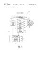
- FIG. 1depicts a typical DVD processing pipeline in which a DVD data stream is received, for example, from a DVD-ROM drive and/or from a remote device, and converted into a decoded and decompressed digital video signal and corresponding digital audio signal(s).
- a DVD data streamconsists of sequential data packets, each of which typically includes various system information, video information and audio information.
- the DVD video decode pipeline 10 depicted in FIG. 1has been broken down into three high-level processing stages, namely a system stream parsing stage 12 , a video processing stage 14 , and an audio processing stage 16 . Additional information regarding these processing stages and others, and the DVD and MPEG-2 standards are provided in the DVD specification, entitled DVD Specification, Version 1.0, August 1996, and in the MPEG-2 video specification ISO/IEC 13818-1, 2, 3 is available from ISO/IEC Copyright Office Case Postale 56, CH 1211, Geneve 20, Switzerland, each of which are incorporated herein, in their entirety and for all purposes, by reference.
- the incoming DVD data streamis split or demultiplexed and/or descrambled, for example using CSS decryption techniques, into three independent streams: a MPEG-2 video stream 15 , a MPEG-2 (or AC-3) audio stream 17 , and a sub-picture stream 13 .
- the MPEG-2 video stream 15can have a bit-rate as high as approximately 9 Mb per second
- the audio stream 17can have a bit-rate as high as approximately 384 Kb per second.
- the sub-picture stream 13tends to have a relatively lower bit-rate, and includes sub-picture information that can be incorporated into the final digital video signal as on-screen displays (OSDS), such as menus or closed captioning data.
- OSDSon-screen displays
- the MPEG-2 video stream 15 and sub-picture stream 13are then provided to video processing stage 14 for additional processing.
- the audio stream 17is provided to audio processing stage 16 for further processing.
- Video processing stage 14includes three sub-stages.
- the first sub-stageis a DVD sub-picture decode 18 stage in which the sub-picture stream 13 is decoded in accordance with the DVD specification.
- DVDallows up to 32 streams of sub-picture that can be decoded into a bitmap sequence composed of colors from a palette of sixteen colors.
- the decoded sub-picturesare typically OSDs, such as menus, closed captions and sub-titles.
- the sub-picture(s)are intended to be blended with the video for a true translucent overlay in the final digital video signal.
- the second sub-stage of video processing stage 14is a MPEG-2 decode sub-stage 20 in which the MPEG-2 video stream is decoded and decompressed and converted to a YUV 4:2:2 digital video signal.
- MPEG-2 decode sub-stage 20conducts a Variable Length Decode (VLD) 22 , an inverse quantization (IQUANT) 24 , an Inverse Discrete Cosine Transform (IDCT) 26 , motion compensation 28 , and a planar YUV 4:2:0 to interleaved 4:2:2 conversion 30 .
- VLDVariable Length Decode
- IQUANTinverse quantization
- IDCTInverse Discrete Cosine Transform
- I frames or picturesare “intra” coded such that the entire picture is broken into 8 ⁇ 8 blocks which are processed via a Discrete Cosine Transform (DCT) and quantized to a compressed set of coefficients that, alone, represent the original picture.
- DCTDiscrete Cosine Transform
- the MPEG-2 specificationalso allows for intermediate pictures, between “I” pictures, which are known as either predicted (“P” pictures) and/or bidirectionally-interpolated pictures (“B” pictures). In these intermediate pictures, rather than encoding all of the blocks via DCT, motion compensation information is used to exploit the temporal redundancy found in most video footage.
- MPEG-2By using motion compensation, MPEG-2 dramatically reduces the amount of data storage required, and the associated data bit-rate, without significantly reducing the quality of the image.
- motion compensationallows for a 16 ⁇ 16 “macroblock” in a P or B picture to be “predicted” by referencing a macroblock in a previous or future picture.
- motion vectorsMPEG-2 is able to achieve high compression ratios while maintaining high quality.
- the resulting YUV 4:2:2 and decoded sub-picture digital video signalsare then provided to the third sub-stage 21 of video processing stage 14 which the YUV 4:2:2 and decoded sub-picture digital video signals are blended together in an alpha blend process 32 to produce a translucent overlay, as described above and in detail in the DVD specification.
- the blended digital video signalis provided to a YUV-to-RGB conversion process 34 , in which the blended digital video signal is converted from a YUV format into a corresponding red-green-blue (RGB) format.
- RGB digital video signalis then provided to an image scaling process 36 , in which the RGB digital video signal is scaled to a particular size for display.
- the resulting final digital video signalis then ready to be displayed on a display device, or otherwise provided to other devices, such as video recording or forwarding devices.
- the final digital video signalcan be displayed on a monitor or CRT by further converting the final digital video signal (which is in RGB format) to an analog RGB video signal.
- the processing stages/sub-stages associated with DVD processing pipeline 10tend to be extremely compute intensive.
- the MPEG-2 video formatwhich is the most compute intensive portion of pipeline 10 , was chosen for DVD technologies because it provides the best quality playback across a range of differing display formats, and is well suited to DVD's higher bit-rates and storage capacity.
- MPEG-2 videois flexible and scalable and can be used to support a wide range of display formats and aspect ratios, from standard interlaced NTSC to high-definition, 16:9 progressive scans.
- One example of a compute intensive MPEG-2 display formatis the Main-Profile, Main-Level (MPML) MPEG-2 format, which supports a 720 ⁇ 480 pixel display operating at 60 fields/sec or 30 frames per second (fps).
- the audio streamis provided by system stream parsing stage 12 to audio processing stage 16 .
- Audio processing stage 16decodes either Dolby AC-3, with 6 channels (e.g., 5.1 channels) of audio for high-quality surround sound reproduction, as specified for use in NTSC compliant devices, or MPEG-2 (up to 7.1 channels), as specified for in PAL and SECAM compliant devices.
- the resulting final digital audio signalis capable of being reproduced, for example, by conversion to an analog signal that is provided to an audio reproduction device, such as a sound generating device that converts the digital audio signal to an analog signal, amplifies or otherwise conditions the analog signal, and provides the signal to one or more speakers.
- decoding the audio streamtends to be much less compute intensive than decoding the video stream.
- the first type of solutionplaces the DVD processing task entirely on the processor within the computer, and as such is a software-only solution.
- softwaree.g., computer instructions
- the PC's processorwould need to be sufficiently powerful enough (e.g., operating speed).
- the latest Intel Pentium II processor based platformsare only able to provide frame rates up to about 24 frames per second (fps).
- the Pentium II based platformsrequire additional hardware support, typically to complete the motion compensation process 28 .
- some software-only solutionssimplify the alpha blend process 36 by simply selecting, on a pixel by pixel basis, to display either the sub-picture pixel or the MPEG derived pixel, rather than actually blending the two pixels together to provide a translucent effect. Again, short cuts such as these tend to diminish the DVD capabilities and can result in non-compliant devices.
- the second type of solutionplaces the DVD processing task entirely on the PC's hardware, without requiring the processor.
- This hardware-only solutiontends to free up the processor.
- providing such specialized circuitrye.g., a DVD decoder
- the specialized circuitrycan be very expensive and result in significantly increased costs, which can be devastating in the highly competitive PC market.
- the specialized circuitrycan also reduce the performance of the PC by requiring access to the PC's bus(es), interfaces and memory components, in some PC architectures.
- the third type of solutionis a hybrid of the first two types of solutions, and requires that the DVD processing tasks be distributed between the PC's processor (i.e., software) and specialized circuitry (e.g., a decoder) that is configured to handle a portion of the processing.
- the hybrid solutionis flexible, in that it allows for different configurations that can be fine-tuned or modified for a given PC architecture/application. However, there is still an additional expense associated with the specialized circuitry, which can increase the consumer's cost.
- the present inventionprovides an improved and cost effective hybrid solution in the form of methods and apparatus that allow DVD data streams to be played back in a computer system.
- the methods and apparatusallow for compliant DVD and/or MPEG-2 video playback by conducting specific decoding processes in a graphics engine that is also capable of generating graphics based on command signals.
- an apparatusfor use in a computer system having a processor to support graphics generation and digital video processing.
- the apparatusincludes a set-up engine, a converter and a texture mapping engine.
- the set-up engineis responsive to at least one command signal from the processor and converts vertex information within the command signal into corresponding triangle information.
- the triangle informationdescribes a triangle in a three dimensional space.
- the converterdetermines digital pixel data for the triangle based on the triangle information.
- the texture mapping enginemodifies the digital pixel data based on the triangle information and at least one digital texture map.
- the apparatussupports graphics generation.
- the texture mapping enginealso generates motion compensated digital image data based on at least one digital image map and at least one motion vector to support digital video processing.
- the digital image mapis a macroblock containing a digital pixel data from a MPEG generated I and/or P picture.
- the texture mapping engineincludes at least one bilinear interpolator that determines interpolated digital pixel data based on a first and a second digital pixel data.
- the bilinear interpolatoris used to perform a bilinear filtering of a macroblock that is on sub-pixel sample points to generate one predicted macroblock that is on pixel sample points.
- the texture mapping engineperforms a first bilinear filtering based on a first motion vector and on a second bilinear filtering based on a second motion vector, and averages the results of the first bilinear filtering and the results of the second bilinear filtering to generate one predicted macroblock.
- the apparatusis configured to add an IDCT coefficient to the digital pixel data as generated by the texture mapping engine. As such, certain embodiments of the present invention are capable of supporting MPEG-2 motion compensation processing.
- the apparatusis further configured to generate a YUV 4:2:2 formatted picture by providing vertical upscaling, and interleaving of a YUV 4:2:0 formatted picture.
- the above stated needs and othersare also met by a computer system, in accordance with one embodiment of the present invention, that is capable of providing video playback of an encoded data stream.
- the computer systemincludes a processor, a data bus mechanism, a primary memory, a display device, and a graphics engine that is configured to generate digital image data based on at least one command signal from the processor, generate motion compensated digital image data based on at least one digital image and at least one motion vector, convert a YUV 4:2:0 formatted picture to a YUV 4:2:2 formatted picture, convert the YUV 4:2:2 formatted picture to a RGB formatted picture, scale the RGB formatted picture, and convert the RGB formatted picture to an analog signal that can be displayed on the display device.
- a methodfor generating graphics and processing digital video signals in a computer system.
- the methodincludes using a graphics engine to generate digital image data, based on at least one command signal by converting vertex information within the command signal into corresponding triangle information, determining digital pixel data for the triangle, based on the triangle information, and modifying the digital pixel data based on the triangle information and at least one digital texture map.
- the methodfurther includes using the same graphics engine to generate motion compensated digital image data by generating motion compensated digital image data based on at least one digital image map and at least one motion vector.
- the methodfurther includes using the same graphics engine to convert a YUV 4:2:0 formatted picture to a YUV 4:2:2 formatted picture by offsetting at least a portion of the YUV 4:2:0 formatted picture and selectively mapping samples of the YUV 4:2:0 formatted picture to a corresponding destination picture to provide a vertical upscaling, and selectively arranging byte data of the destination picture to interleave the byte data and generate the YUV 4:2:2 formatted picture.
- FIG. 1is block diagram depicting a typical prior art DVD processing pipeline for use with a computer
- FIGS. 2 a and 2 bare block diagrams depicting typical prior art computer systems that are configured to conduct all or a portion of the DVD processing pipeline of FIG. 1;
- FIG. 3is a table depicting the results of an analysis of an exemplary computer system conducting specific portions of the DVD processing pipeline of FIG. 1 in which the relative workload burden (percentage) placed on the computer system's processor is listed along with a relative estimated measurement of the same or similar DVD related process being conducted in a hardware implementation alone, in accordance with one embodiment of the present invention;
- FIG. 4is a block diagram depicting an exemplary graphics accelerator having a 3D graphics engine for use in a computer system, as in FIG. 2 a , in accordance with the present invention
- FIG. 5is a block diagram depicting an exemplary 3D graphics processing pipeline for use in the graphics accelerator of FIG. 4, in accordance with the present invention
- FIG. 6is a block diagram depicting an exemplary 3D graphics engine having a rasterizer for use in the graphics accelerator in FIG. 4, in accordance with the present invention
- FIG. 7is a block diagram depicting an exemplary rasterizer having a scan texture mapping engine, raster operations and pixel packing logic, for use in the 3D graphics engine of FIG. 6, in accordance with the present invention
- FIG. 8is a block diagram depicting a computer system having a processor, a modified graphics accelerator and a frame buffer, in accordance with one embodiment of the present invention
- FIG. 9is a block diagram depicting the allocation of memory within the frame buffer of the computer system in FIG. 8, in accordance with one embodiment of the present invention.
- FIGS. 10 a through 10 care block diagrams depicting a mapping sequence for Y, U and V image data as mapped by the pixel packing logic of the rasterizer in FIG. 7, in accordance with one embodiment of the present invention
- FIG. 11is a block diagram depicting a raster operations of the rasterizer in FIG. 7, in accordance with one embodiment of the present invention.
- FIG. 12is a block diagram of a pixel packing logic, of FIG. 7, having a plurality of multiplexers for mapping Y, U and V image data, in accordance with one embodiment of the present invention.
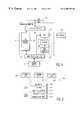
- FIG. 2 adepicts a typical PC system 40 having a processor 42 that is configured with a software-only solution, as represented by DVD processing pipeline computer instruction set 44 .
- Processor 42represents one or more processors, such as, for example, an Intel Pentium family processor or Motorola PowerPC processor.
- Processor 42is coupled to a chip set 46 .
- Chip set 46provides access to/from processor 42 , to/from a primary memory, such as dynamic random access memory (DRAM) 48 , and to/from one or more data bus(es), such as, peripheral component interface (PCI) bus 50 and/or ISA bus 52 .
- DRAMdynamic random access memory
- PCIperipheral component interface
- a graphics accelerator 54is also coupled to PCI bus 50 and is configured to interface with processor 42 and/or DRAM 48 via PCI bus 50 and chip set 46 , or other devices (not shown) on PCI bus 50 and/or ISA bus 52 .
- Graphics accelerator 54is coupled to a double buffering, frame buffer 56 and is configured to output an analog video signal to display 58 .
- ISA bus 52which typically has a lower bit-rate than PCI bus 50 , is provided to allow one or more devices to be coupled to ISA bus 52 through which they can interface with processor 42 , DRAM 48 , or other devices on PCI bus 50 and/or ISA bus 52 .
- a sound reproduction device 60is depicted as being coupled to ISA bus 52 .
- Sound reproduction device 60is configured to receive the final digital audio signal from processor 42 and output corresponding audio tones, or sound.
- At least one storage device 62is also shown as being coupled to ISA bus 52 .
- Storage device 62represents a variety of storage devices, including, for example, a disk drive, a tape drive, and/or an optical storage device (e.g., read only memory (ROM) and/or RAM) such as a CD, or DVD drive.
- ROMread only memory
- RAMrandom access memory
- FIG. 2 afor example, if storage device 62 is a DVD-ROM then during playback a DVD data stream is provided to processor 42 , through ISA bus 52 and chip set 46 .
- the DVD data stream that is output by storage device 62is typically retrieved from the DVD and may be have been decrypted or otherwise processed by storage device 62 prior to being provided to processor 42 .
- processor 42completes the DVD processing in accord with DVD processing pipeline computer instruction set 44 . This processing typically includes accessing DRAM 48 through chip set 46 , for example, to store/retrieve intermediate data during processing.
- the final digital video signalis then provided by processor 42 to graphics accelerator 54 , through chip set 46 and PCI bus 50 .
- Graphics accelerator 54stores the final digital video signal within buffer 56 , and subsequently retrieves the final digital video signal from buffer 56 , converts the final digital video signal into a final analog video signal, for example, using a digital-to-analog converter (DAC).
- DACdigital-to-analog converter
- the final analog video signalis then provided to display device 28 .
- Processor 42also provides the final digital audio signal to sound reproduction device 60 , which converts the final digital audio signal to sound.
- FIG. 2 bis similar to FIG. 2 a , and as such like reference numerals refer to like components.
- FIG. 2 bdepicts a PC system 40 ′, which is configurable either as a hardware-only solution or as a hybrid solution. As shown, in FIG. 2 b , additional specialized processes/circuitry is provided, as represented by decoder 64 .
- system 40 ′When system 40 ′ is configured as a hardware-only solution, significantly all of the DVD processing pipeline in FIG. 1 is completed in decoder 64 . When configured as a hybrid solution, system 40 ′ will have a portion of the DVD processing pipeline (e.g., see FIG. 1) being completed by processor 42 prior to, and/or following, partial processing by decoder 64 . For example, decoder 64 can be configured to complete motion compensation process 28 .
- the natural advantage of the software-only solutionis cost-effectiveness (ignoring the cost of the processor 42 ).
- the software-only solutionexploits the processing power that already exists ( and the customer has already paid for) to deliver DVD playback for essentially no incremental cost.
- the downsideis that today's software-only solutions tend to fall short on frame rate, quality and functionality, and are limited by a lack of processing speed in the typical processor. For example, even with the recent addition of MMXTM technology, neither 1997's mainstream PentiumTM nor even 1998's mainstream Pentium IITM machines will provide smooth, broadcast quality DVD playback at the full 30 fps.
- One problem with simply adding hardwareis cost.
- the notoriously competitive PC graphics controller markethas historically resisted higher prices for graphics controllers and additional decoders. Indeed, graphic controller chip prices have remained remarkably flat and have even decreased over time, despite increased capabilities. This requires the manufacturers of graphics accelerators and other like chips to be extremely judicious as to how much functionality to commit to hardware.
- a decoder 64 for use in a hardware-only solutionwill likely consume at least approximately 72,000 gates of logic (or equivalent) to effectively process MPEG-2 system, audio and video decode.
- adding the functionality of decoder 64 to an existing graphics acceleratorwould also appear unreasonable, because in today's cost-effective CMOS processes, gate counts in this range are usually too prohibitive in cost to consider for inclusion in a mainstream PC graphics accelerator chip.
- supporting DVD playback with a hardware-only solutiondoes not appear to be a viable solution in the near term for the bulk of the PC market.
- the mainstream desktop PCwould provide the quality and performance of a hardware-only solution with the cost effectiveness of a software-only implementation.
- Thiscalls for a cost-effective hybrid solution.
- the present inventionprovides methods and apparatus for a very cost-competitive hybrid solution that combines the performance of a hardware solution and the cost and simplicity of a software solution.
- Results of this analysisfor an exemplary architecture, are shown in the table in FIG. 3 . Based on this analysis, it was determined that the high-level decode of system and security layers and MPEG-2 VLD were ruled out of consideration for hardware implementation, since these tasks are not overwhelmingly compute intensive and much better suited to the general purpose programmability of the processor 42 , rather than, for example, a modified graphics accelerator.
- the IDCT and IQUANT processeswere eliminated from consideration, since the processor overhead was relatively small, and hardware impact would be significant.
- the IDCT and IQUANT processestend to rely heavily on multiplies, adds, and multiply-accumulate (MAC), operations, which, for example, Pentium IITM—class processors (particularly those with MMXTM technology) execute fairly well.
- MACmultiply-accumulate
- AC-3 audiowas also eliminated from consideration for several reasons. Foremost, it doesn't require a dominant share of the processor time due in part, for example, to MMXTM assistance available on some processors.
- the audio processingalso tends to require the addition of non-trivial hardware size and complexity. Since audio and graphics/video are usually physically separated within today's mainstream PC architecture, it made more sense to leave AC-3 processing either to the processor 42 or an audio subsystem rather than attempting to do it in a modified graphics accelerator.
- the methods and apparatus of the disclosed embodimentpresent a unique hybrid solution, which achieves full-frame, compliant DVD, by modifying the existing graphics accelerator hardware and software driver, at virtually no additional cost to the consumer.
- certain three dimensional (3D) texture mapping processeswhich are typically supported by most of the existing 3D engines within a typical graphics accelerator, have been identified as being similar to the motion compensation and YUV 4:2:0-to-4:2:2 conversion processes.
- FIG. 8which is similar to FIG. 1 a , depicts an improved computer system 80 having processor 42 configured to run a portion 44 ′ of the DVD process pipeline and a modified graphics accelerator 84 , in accordance with one embodiment of the present invention.
- a 3D graphics engine within modified graphics accelerator 84performs the motion compensation, YUV 4:2:0-to-4:2:2 conversion, and/or alpha blending processes, an exemplary 3D graphics engine/process is described in greater detail below.
- FIG. 4is a block diagram of an exemplary graphics accelerator 54 .
- graphics accelerator 54includes a system interface 90 , which is coupled to PCI bus 50 , or alternatively to an advanced graphics port (AGP) on chip set 46 .
- System interface 90is configured to provide an interface to PCI bus 50 (or the AGP) through which graphics generating commands are received, for example from processor 42 .
- a 3D graphics engine 92is coupled to system interface 90 .
- 3D graphics engine 92is configured to generate 2D images based on 3D modeling information.
- the 2D images from 3D graphics engine 92are typically digital images in a RGB format.
- the 2D images from 3D graphics engine 92are stored in frame buffer 56 , via memory controller 94 .
- Memory controller 94provides an interface to frame buffer 56 .
- DAC 99converts the digital RGB signal into a corresponding analog RGB signal that is then provided to display device 58 and displayed thereon.
- graphics accelerator 54is depicted as having a YUV converter 95 for use in playing back YUV 4:2:2 formatted digital images.
- YUV converter 95includes a RGB converter 96 , which is coupled to memory controller 94 and configured to convert the YUV 4:2:2 formatted digital image into a corresponding RGB digital image.
- the output of RGB converter 96is provided to a scalar 98 , which is coupled to RGB converter 96 and configured to scale the RGB digital image to a size that is appropriate for the selected display device 58 .
- DAC 99is coupled to the output of scalar 98 and configured to convert the scaled RGB digital image into a corresponding RGB analog signal that is suitable for driving display device 58 .
- FIG. 5depicts a 3D graphics pipeline 200 as is typically found in the software of processor 42 and 3D graphics engine 92 .
- 3D graphics pipeline 200starts with a 3D model 202 of an object as defined by a set of vertices or similar coordinates.
- a housecan be modeled as a set of vertices that define the polygons or other shapes of the house.
- the vertices of the 3D model 202are typically output by the application software running on processor 42 .
- the application softwarealso defines additional information regarding the lighting 204 and the applicable observation view-point 206 with respect to the object.
- a housemay be illuminated by the sun and viewed from a particular location with respect to the house and sun.
- the geometry process 208essentially adjusts (e.g., positions scales) the 3D model 202 to where the view-point 206 is.
- the lighting process 210then considers the location of the lighting source(s) 204 and the view-point 206 with respect to the surfaces of the 3D model 202 to adjust the shading and/or colors of these surfaces accordingly.
- map to view-port process 212maps the polygons or vertices of the 3D object's viewable regions to a two dimensional (2D) plane, creating a 2D image.
- a typical map to view port process 212includes a 2D perspective rendering algorithm that creates a 2D image that appears to have depth when viewed, for example on a display device.
- the triangle set-up process 214determines how to represent these continuous surfaces as triangles having particular characteristics such as location, colors, and texture coordinates, etc.
- the triangle set-up process 214also provides information to the triangle rasterize process 216 regarding how the triangle is oriented with respect to the view point 206 .
- the triangle rasterize process 216performs this function by converting each triangle, as defined by the triangle set-up process, into corresponding pixels having particular colors. To accomplish this, the triangle rasterize process 216 typically includes a scan conversion process (not depicted) and a texture mapping process (not depicted). The scan conversion process identifies the required pixels and the texture mapping process identifies the particular color for each of the pixels.
- the geometry 208 , lighting 210 and map to view point 212 processesare completed by application software running processor 42 , and the triangle set-up 214 and triangle rasterize 216 processes are implemented in the hardware of the graphics accelerator 54 , and in particular 3D graphics engine 92 .
- FIG. 6depicts the triangle set-up 214 and triangle rasterize 216 processes as implemented in an exemplary 3D graphics engine 92 .
- commandsare received by a command interface 100 , which is coupled to the system interface 90 .
- the commandsinclude 3D graphics commands and associated parameters, such as vertex information, as provided by processor 42 through system interface 90 .
- vertex informationsuch as vertex information
- processor 42through system interface 90 .
- one commandmight be to “draw a triangle”.
- the commandscan be provided directly to a particular component(s) or stored in a commend register 102 .
- a set-up engine 104is coupled to the command interface 100 and is typically responsive thereto.
- triangle set up engine 104can receive vertex information regarding the triangle that is to be drawn from command interface 100 .
- the vertex informationtypically includes the positional coordinates (e.g., X, Y, and Z), color, texture coordinates (U and V, note that the U and V parameters do not represent chrominance in this situation), a homogeneous parameter (W), and possibly other parameters.
- Triangle set-up engine 104processes the vertex information into triangle information, that, for example, can include information relating to the triangle (e.g., vertex 1 , vertex 2 and vertex 3 ), the edges of the triangle (e.g., edge 1 , edge 2 and edge 3 ), and slopes (e.g., dX/dY, dU/dY and dV/dY).
- triangle informationcan include information relating to the triangle (e.g., vertex 1 , vertex 2 and vertex 3 ), the edges of the triangle (e.g., edge 1 , edge 2 and edge 3 ), and slopes (e.g., dX/dY, dU/dY and dV/dY).
- a rasterizer 106is coupled to triangle set-up engine 104 and is configured to convert the triangles as defined by the triangle information into corresponding digital RGB pixel information. For example, the texture coordinates and slopes for those coordinates are used to apply a particular type of texture to a surface of the triangle being drawn. To accomplish this, the rasterizer 106 typically scan converts the triangle into an appropriate number of pixels, and determines the particular color for each pixel based on a mapping of a specific texture to each of the pixels. For example, a wall surface of a house may have a wood grain pattern that is to be applied to the displayed image, and therefore the triangle or triangles that represent the wall will have corresponding texture coordinates for the desired wood grain texture and the orientation of the wall.
- each of the textured (e.g., wood grained) triangles that represent the wall of a houseis scan converted to an appropriate number of RGB pixels, and each of these pixels has a texel (i.e., texture color value) mapped to it to set a particular color.
- Rasterizer 106is also configured to store the resulting digital RGB pixel information at selected addresses within frame buffer 56 , through memory controller 94 , for example.
- FIG. 7us a block diagram depicting an exemplary rasterizer 106 .
- Rasterizer 106typically includes a scan converter 108 and a texture mapping engine 110 .
- Scan converter 108is coupled to triangle set-up engine 104 and receives triangle information, including, for example, positional coordinates, and edge and slope information therefrom.
- Scan converter 108determines which pixels are within the triangle and establishes corresponding addresses for the “on screen” portion (see FIG. 9) of the frame buffer 56 , which is used for displaying the triangle.
- frame buffer 56is depicted as being subdivided into an “on screen” portion 120 which contains the current image that is being built by rasterizer 106 , and an “off screen” portion 122 that contains intermediate data, such as various texture maps 124 a-n , that is used to create/modify the current image that is stored in the on screen portion 120 .
- the addresses determined by scan converter 108 in FIG. 7can, for example, be stored in the off screen portion 122 of frame buffer 56 by scan converter 108 , through memory controller 94 . These triangle addresses will be used by texture mapping engine 110 .
- texture mapping engine 110is coupled to scan converter 108 and is configured to receive the texture related information, including, for example, U, V, W, and related slope information therefrom.
- Texture mapping engine 110determines a texture address for each pixel and retrieves a texture color from a texture map (e.g., 124 a ) within the off screen portion 122 of frame buffer 56 .
- Texture mapping engine 110typically includes a plurality of interpolators 112 that are configured to incrementally calculate the intermediate texture values based on starting points and slopes for U, V and W. Based on the results of interpolators 112 , a texel is retrieved from the texture map 124 a and assigned to each of the pixels. The texels for each of the pixels is then stored at the corresponding address (or addresses) in on screen portion 120 of frame buffer 56 for each pixel, by texture mapping engine 110 through memory controller 94 .
- motion compensationcan be selected per macroblock by the encoder, and is typically utilized heavily to reduce the bitstream.
- Decoding a motion compensated macroblockconsists of calculating a predicted macroblock from one or more sources and adding to that macroblock coefficient data output from the IDCT (preferably computed by processor 42 ), one coefficient per pixel. This process is then repeated for each plane of the Y, U and V samples.
- MPEG-2According to the MPEG-2 specification several encoding modes allow two reference macroblocks to be averaged to create one predicted macroblock, and each of those references may align to Y2 pixel boundaries. Moreover, MPEG-2 allows a range of ⁇ 256 to 255 for error coefficients per pixel. This of course translates to 9-bits of precision, which is more cumbersome to handle than byte-aligned 8-bit data. Finally, MPEG-2 supports modes which specifies two predictions for a macroblock, that is a dual-prime prediction for P pictures and a bidirectional prediction for B pictures. In these cases, the two predictions must be averaged to create the combined prediction.
- Equation 1calculates the final predicted pixel values for each coordinate ⁇ x, y ⁇ from two references. Equation 2 adds in the IDCT output per pixel to the motion compensated output for each macroblock pixel at coordinates ⁇ x, y ⁇ .
- F pred ( x, y )[F pred1 ( x, y )+ F pred2 ( x, y )]/2 (1)
- the commercially available Philips 9727 graphics acceleratorrepresents a typical state-of art graphics accelerator, which, for example, is capable of producing 3D graphics based on control signals received from processor 42 (as depicted in FIGS. 4 - 7 ).
- the Philips 9727is used herein as an example only to demonstrate the methods and apparatus of the present invention.
- Those skilled in the artwill recognize, based on the present invention, that other existing or future graphics accelerators and/or 3D graphics engines (regardless of location) can be modified and/or used to provide DVD and/or MPEG-2 related processing.
- texture mapping engine 110in applying textures to triangles, is performing the nearly the same operation as that required for the motion compensation process 28 in decoding MPEG-2 video.
- MPEG-2 motion compensationutilizes motion vectors to identify square-shaped macroblocks of pixels (or picture elements (pels)) from previous and/or subsequent pictures that are to be used to generate the current B or P picture.
- These predicted blocksare essentially textures, and in this manner, the I and/or P picture(s) from where these predicted blocks are gathered are essentially texture maps similar to texture maps 124 a-n .
- the only difference between this type of predicted block of MPEG-2 and a triangle used in the rasterizeris the shape.
- texture mapping engine 110 within rasterizer 106can also be used to determine this type of predicted block as part of the motion compensation process 28 .
- FIG. 9an I picture 126 and a P picture 128 are illustrated along side texture maps 124 a-n with off screen portion 122 of frame buffer 56 .
- a typical state-of-the-art texture mapping engine 110includes a bilinear filtering capability (e.g., interpolators 112 ) that is used to enhance the texel color when, for example, the view point is sufficiently close to the textured surface (e.g., magnification). For example, if the view point of the wood grained wall of the house were to be very close to the wall, then there could be a tendency for the texture map 124 a-n to be mapped to the wall such that the resulting image appears granular. This is because the resolution of most texture maps 124 a-n is about 128 by 128 texels. By providing a bilinear filtering capability, which essentially interpolates between adjacent texels, this potential granularity is reduced. Thus, bilinear filtering is simply bilinear interpolation of a texture. Therefore, the 1 ⁇ 2 pixel sampling required by many MPEG-2 motion vectors is supported by the texture mapping engine's 110 bilinear filtering capability.
- texture mapping engine 110would need to bilinear filter each of these motion vectors and then average the two results to produce a predicted block.
- One of the features of a state-of-the-art texture mapping engine 110is the capability to blend (e.g., by averaging texels) and map two textures to a triangle.
- the wood grained wall of the housecould include blended textures mapped from a wood grain texture map and a light map to produce a wood grained wall that has some lighter and some darker areas. Therefore, this multiple-texturing capability of the texture mapping engine 110 can be applied to MPEG-2 motion compensation by simply averaging the bilinear filtered pixels for each of the motion vectors to determine the motion compensated pixel.
- motion compensated macroblocksmay also be specified along with a set of error coefficients, one per texel, as output from the IDCT 26 process.
- Each of these error coefficients (or macroblock coefficients)needs to be added a corresponding pixel.
- a typical 3D graphics engine 92is not configured to perform a signed addition function, as is required to add a macroblock coefficient (which can be between ⁇ 256 and 255).
- the signed addition ROP needed for the MPEG-2 macroblock coefficientis provided.
- an “8-bit signed addition ROP”is provided within modified graphics accelerator 84 to handle the macroblock coefficient signed addition.
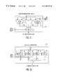
- FIG. 11depicts an exemplary raster operations 114 having existing ROPs 115 a-n and an 8-bit signed adder 130 .
- the outputs form existing ROPs 115 a-n and 8-bit signed adder 130are provided to a multiplexer 132 , which is controlled by control register 102 to select among the ROPs.
- the resulting modified graphics accelerator 84provides MPEG-2 motion compensation. This is an extremely cost-effective implementation of the motion compensation process 28 .
- Equation 28-bit signed adder ROP 130 was provided to add the output of texture mapping engine 110 to the IDCT coefficient which would be fetched from memory either DRAM 48 , or frame buffer 56 . Additionally, the modified graphics accelerator 84 can also be programmed to take a second pass through another set of signed 8-bits to support the full 9-bit error coefficient range, as allowed by MPEG-2.
- the next DVD related process to be offloaded to the graphics acceleratoris the planar YUV 4:2:0-to-4:2:2 conversion process.
- a typical graphics acceleratoris capable of taking YUV 4:2:2 picture and reformatting it to a corresponding RGB picture, conversion from YUV 4:2:0 to YUV 4:2:2 is not usually supported and therefore this functionality needs to be added to the modified graphics accelerator in accordance with the present invention.
- the motion compensation process 28produces final macroblock pixel values for three components, luminance (Y) and chrominance (U and V), which are typically output in a planar format commonly referred to as YUV 4:2:0.
- YUV 4:2:0luminance
- U and Vchrominance
- RGBluminance
- U and Vchrominance
- Converting planar YUV 4:2:0 to an interleaved 4:2:2 formatinvolves reading a byte of data from the planar source and writing the byte to a different location in the destination 4:2:2 plane.
- MPEG-2's 4:2:0 planar schemedoes not specify chroma sample points on pixel centers vertically (as it does horizontally).
- to upsample interlaced video datatechnically requires a 2-tap vertical filter of ⁇ 1 ⁇ 4, 3 ⁇ 4 ⁇ , ⁇ 1 ⁇ 2, 1 ⁇ 2 ⁇ or ⁇ fraction ( 3 / 4 ) ⁇ , ⁇ fraction ( 1 / 4 ) ⁇ , depending on whether the picture is an odd or even field and whether the line is odd or even within the field.
- Thisrequires at least a read of 2 sample points and one or two adds and a shift per pixel, again this is typically far too taxing for a software-only solution. Therefore, software-only solutions are usually forced to compromise optimal quality and take a shortcut by selecting the nearest chroma sample point and replicating vertically as required. Such an approximation leads to colors that are not correctly aligned with intensity and results in compromised picture quality.
- converting planar YUV 4:2:0 to interleaved 4:2:2also can be performed via texture mapping engine 110 within 3D graphics engine 92 .
- the Y, U and V picturescan be broken into squares measuring a power of two a side. Each square becomes the source texture, which is mapped to the destination 4:2:2 picture; in the case of U and V, texture mapping engine 110 is instructed to magnify (upscale) by 2X in Y.
- One pass through each Y, U and V pictureis required to complete the task.
- the output data path following texture mapping engine 110is modified to allow generated texels to be channeled to specific byte lanes at specific offsets and increments, while other byte lanes would be masked on the write to the destination. This allows the Y, U and V values to be written to their proper byte locations, without overwriting the results of a previous pass.
- thisamounted to adding four 8-bit registers 140 a-d in the existing data path, as depicted in FIG. 12, as being added to pixel packing logic 116 , which is coupled to receive the output from raster operations 114 .
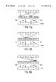
- FIGS. 10 a , 10 b and 10 cdepict the byte lane arrangements for Y, U and V, respectively.
- the Y values (Y 0-4 )are selectively mapped (via registers 140 b , 140 d , 140 b , and 140 d , respectively) which results in an offset pattern 150 a in which a Y value is placed once every two bytes.
- the U values (U 0-4 )are selectively mapped (via register 140 c ) which results in an offset pattern 150 b in which a U value is placed once every four bytes.
- the V values (V 0-4 )are selectively mapped (via register 140 a ) which results in an offset pattern 150 c in which a V value is placed once every four bytes.
- texture mapping engine 110By simply adding (or subtracting) an offset of ⁇ 1 ⁇ 4, 1 ⁇ 2, or 3 ⁇ 4 ⁇ to the starting texture address which points to the source 4:2:0 picture, texture mapping engine 110 bias all subsequent texture sample points, which essentially mimics the effects of the vertical filter. As such, unlike competing solutions, the methods and apparatus of the present invention are able to provide the proper, high quality upsampling as the MPEG-2 specification intended.
- the decoded MPEG-2 videoneeds to be alpha blended with the sub-picture(s).
- the video componentFor each pixel within each picture, the video component must be blended with the sub-picture component to produce the final output pixel via the following equation, where “a” (alpha) provides 16 levels of blend between the video color and the sub-picture color (one of possible 16 colors):
- F out ( x, y )F YUV422 ( x, y )* a+F subpict ( x, y )*(1 ⁇ a ) (3)
- the sub-picture alpha blending processis provided by making a minor change to the existing architecture of the 3D graphics engine 92 , which essentially extends the display refresh circuits (not shown).
- the display refresh circuits in the 3D graphics engine 92 of the 9727for example, already support the mixing of 2 layers of bitmapped data; one can be YUV 4:2:2 and the other a variety of RGB formats.
- the YUV 4:2:2is, therefore, converted to RGB and mixed on a per pixel basis with the second RGB layer via color key.
- the existing mixing capabilitycan be extended to support true translucent overlay of the sub-picture on the video.
- Each sub-picture pixelis represented with a 4-bit index to the table and accompanying 4-bit blend value.
- the 3D graphics engineconverts the YUV 4:2:2 video pixel to RGB, does a table lookup to get the RGB value for the sub-picture and then performs the blend via 2 multiplies and an add, as shown in Equation 3, above.
- the methods and apparatus of the present inventionprovide a modified graphics accelerator 84 that is also capable of performing DVD playback along with the processor.
- the 9727 graphics acceleratorwas modified (as described above) to implement motion compensation, YUV 4:2:0-to-4:2:2 conversion and alpha blending in hardware, to deliver up to 30 frames/sec playback of typical DVD content and bit-rates on a 266 MHz Pentium IITM platform.
Landscapes
- Engineering & Computer Science (AREA)
- Multimedia (AREA)
- Signal Processing (AREA)
- General Engineering & Computer Science (AREA)
- Physics & Mathematics (AREA)
- General Physics & Mathematics (AREA)
- Theoretical Computer Science (AREA)
- Computer Graphics (AREA)
- Computer Hardware Design (AREA)
- Image Generation (AREA)
- Television Signal Processing For Recording (AREA)
- Testing, Inspecting, Measuring Of Stereoscopic Televisions And Televisions (AREA)
Abstract
Description
Claims (10)
Priority Applications (7)
| Application Number | Priority Date | Filing Date | Title |
|---|---|---|---|
| US08/963,931US6208350B1 (en) | 1997-11-04 | 1997-11-04 | Methods and apparatus for processing DVD video |
| PCT/IB1998/001755WO1999023831A2 (en) | 1997-11-04 | 1998-11-02 | Methods and apparatus for processing dvd video |
| KR1019997006085AKR100604102B1 (en) | 1997-11-04 | 1998-11-02 | Method and apparatus for processing digital multi-purpose disc video |
| CNB988030667ACN1230790C (en) | 1997-11-04 | 1998-11-02 | Method and apparatus for processing DVD video |
| JP52582899AJP2001508631A (en) | 1997-11-04 | 1998-11-02 | Method and apparatus for processing DVD video |
| EP98949195AEP1002428A2 (en) | 1997-11-04 | 1998-11-02 | Methods and apparatus for processing dvd video |
| US09/677,823US6538658B1 (en) | 1997-11-04 | 2000-09-30 | Methods and apparatus for processing DVD video |
Applications Claiming Priority (1)
| Application Number | Priority Date | Filing Date | Title |
|---|---|---|---|
| US08/963,931US6208350B1 (en) | 1997-11-04 | 1997-11-04 | Methods and apparatus for processing DVD video |
Related Child Applications (1)
| Application Number | Title | Priority Date | Filing Date |
|---|---|---|---|
| US09/677,823DivisionUS6538658B1 (en) | 1997-11-04 | 2000-09-30 | Methods and apparatus for processing DVD video |
Publications (1)
| Publication Number | Publication Date |
|---|---|
| US6208350B1true US6208350B1 (en) | 2001-03-27 |
Family
ID=25507913
Family Applications (2)
| Application Number | Title | Priority Date | Filing Date |
|---|---|---|---|
| US08/963,931Expired - LifetimeUS6208350B1 (en) | 1997-11-04 | 1997-11-04 | Methods and apparatus for processing DVD video |
| US09/677,823Expired - LifetimeUS6538658B1 (en) | 1997-11-04 | 2000-09-30 | Methods and apparatus for processing DVD video |
Family Applications After (1)
| Application Number | Title | Priority Date | Filing Date |
|---|---|---|---|
| US09/677,823Expired - LifetimeUS6538658B1 (en) | 1997-11-04 | 2000-09-30 | Methods and apparatus for processing DVD video |
Country Status (6)
| Country | Link |
|---|---|
| US (2) | US6208350B1 (en) |
| EP (1) | EP1002428A2 (en) |
| JP (1) | JP2001508631A (en) |
| KR (1) | KR100604102B1 (en) |
| CN (1) | CN1230790C (en) |
| WO (1) | WO1999023831A2 (en) |
Cited By (60)
| Publication number | Priority date | Publication date | Assignee | Title |
|---|---|---|---|---|
| US6310659B1 (en)* | 2000-04-20 | 2001-10-30 | Ati International Srl | Graphics processing device and method with graphics versus video color space conversion discrimination |
| US6349167B1 (en)* | 1997-01-06 | 2002-02-19 | Lg Electronics, Inc. | Optical disc reproducing apparatus and method |
| US20020110274A1 (en)* | 2001-01-26 | 2002-08-15 | Hiroshi Yamamoto | Image processing method |
| US20020135696A1 (en)* | 2001-02-20 | 2002-09-26 | Perlman Stephen G. | System and method for rendering graphics and video on a display |
| US20020163501A1 (en)* | 2000-10-31 | 2002-11-07 | Guillaume Brouard | Method and device for video scene composition including graphic elements |
| US20020196372A1 (en)* | 2001-02-06 | 2002-12-26 | Hirofumi Ito | Image generating method, apparatus and system using critical points |
| EP1286540A1 (en)* | 2001-08-22 | 2003-02-26 | Thomson Licensing S.A. | Consumer electronics appliances with shared memory |
| US6552749B1 (en)* | 1999-01-29 | 2003-04-22 | Intel Corporation | Method and apparatus for video motion compensation, reduction and color formatting |
| US6577320B1 (en)* | 1999-03-22 | 2003-06-10 | Nvidia Corporation | Method and apparatus for processing multiple types of pixel component representations including processes of premultiplication, postmultiplication, and colorkeying/chromakeying |
| US20030151610A1 (en)* | 2000-06-30 | 2003-08-14 | Valery Kuriakin | Method and apparatus for memory management of video images |
| US6621490B1 (en)* | 2000-03-03 | 2003-09-16 | Ati International, Srl | Method and apparatus for motion compensation using hardware-assisted abstraction layer |
| US6628827B1 (en)* | 1999-12-14 | 2003-09-30 | Intel Corporation | Method of upscaling a color image |
| US20030193486A1 (en)* | 2002-04-15 | 2003-10-16 | Estrop Stephen J. | Methods and apparatuses for facilitating processing of interlaced video images for progressive video displays |
| US20030201994A1 (en)* | 1999-07-16 | 2003-10-30 | Intel Corporation | Pixel engine |
| US6658399B1 (en)* | 1999-09-10 | 2003-12-02 | Intel Corporation | Fuzzy based thresholding technique for image segmentation |
| US6674479B2 (en)* | 2000-01-07 | 2004-01-06 | Intel Corporation | Method and apparatus for implementing 4:2:0 to 4:2:2 and 4:2:2 to 4:2:0 color space conversion |
| US20040039954A1 (en)* | 2002-08-22 | 2004-02-26 | Nvidia, Corp. | Method and apparatus for adaptive power consumption |
| US20040046778A1 (en)* | 2002-09-09 | 2004-03-11 | Niranjan Sithampara Babu | System and method to transcode and playback digital versatile disc (DVD) content and other related applications |
| US6741263B1 (en)* | 2001-09-21 | 2004-05-25 | Lsi Logic Corporation | Video sampling structure conversion in BMME |
| US20040101056A1 (en)* | 2001-02-05 | 2004-05-27 | Wong Daniel W. | Programmable shader-based motion compensation apparatus and method |
| US6803968B1 (en)* | 1999-04-20 | 2004-10-12 | Nec Corporation | System and method for synthesizing images |
| US20050024363A1 (en)* | 2003-08-01 | 2005-02-03 | Estrop Stephen J. | Bandwidth-efficient processing of video images |
| US20050024384A1 (en)* | 2003-08-01 | 2005-02-03 | Microsoft Corporation | Strategies for processing image information using a color information data structure |
| US20050030422A1 (en)* | 2003-08-06 | 2005-02-10 | Pasquale Leone | Chroma upsampling method and apparatus therefor |
| US20050063586A1 (en)* | 2003-08-01 | 2005-03-24 | Microsoft Corporation | Image processing using linear light values and other image processing improvements |
| US20050088446A1 (en)* | 2003-10-22 | 2005-04-28 | Jason Herrick | Graphics layer reduction for video composition |
| US6912350B1 (en) | 1999-12-08 | 2005-06-28 | Intel Corporation | DVD subpicture rendering without loss of color resolution |
| US20050206785A1 (en)* | 2000-04-20 | 2005-09-22 | Swan Philip L | Method for deinterlacing interlaced video by a graphics processor |
| US6952211B1 (en)* | 2002-11-08 | 2005-10-04 | Matrox Graphics Inc. | Motion compensation using shared resources of a graphics processor unit |
| US6967659B1 (en)* | 2000-08-25 | 2005-11-22 | Advanced Micro Devices, Inc. | Circuitry and systems for performing two-dimensional motion compensation using a three-dimensional pipeline and methods of operating the same |
| US20060056517A1 (en)* | 2002-04-01 | 2006-03-16 | Macinnis Alexander G | Method of communicating between modules in a decoding system |
| US20060093317A1 (en)* | 2004-10-29 | 2006-05-04 | Ati Technologies, Inc. | Video playback method and apparatus |
| US7158178B1 (en)* | 1999-12-14 | 2007-01-02 | Intel Corporation | Method of converting a sub-sampled color image |
| US7212250B1 (en)* | 1999-07-15 | 2007-05-01 | Thomson Licensing | Method and apparatus for providing on-screen displays for a multi-colorimetry receiver |
| US20080001964A1 (en)* | 2006-06-29 | 2008-01-03 | Spangler Steven J | Simplification of 3D texture address computation based on aligned, non-perspective objects |
| US20080117970A1 (en)* | 2006-11-20 | 2008-05-22 | Samsung Electronics Co., Ltd. | Method and apparatus for encoding and decoding rgb image |
| US7414632B1 (en)* | 2000-01-07 | 2008-08-19 | Intel Corporation | Multi-pass 4:2:0 subpicture blending |
| US20080239152A1 (en)* | 2007-03-29 | 2008-10-02 | Kabushiki Kaisha Toshiba | Sub picture reproducing device, sub picture reproducing method, and sub picture reproducing program |
| US7451457B2 (en) | 2002-04-15 | 2008-11-11 | Microsoft Corporation | Facilitating interaction between video renderers and graphics device drivers |
| US20090087120A1 (en)* | 2007-09-28 | 2009-04-02 | Ati Technologies Ulc | Apparatus and method for generating a detail-enhanced upscaled image |
| US20090147133A1 (en)* | 2007-12-10 | 2009-06-11 | Ati Technologies Ulc | Method and apparatus for high quality video motion adaptive edge-directional deinterlacing |
| US20090160866A1 (en)* | 2006-06-22 | 2009-06-25 | Stmicroelectronics S.R.L. | Method and system for video decoding by means of a graphic pipeline, computer program product therefor |
| US20090167778A1 (en)* | 2007-12-28 | 2009-07-02 | Ati Technologies Ulc | Apparatus and method for single-pass, gradient-based motion compensated image rate conversion |
| US7589788B1 (en)* | 2003-02-28 | 2009-09-15 | Intel Corporation | Method and apparatus for video motion compensation, reduction and color formatting |
| US7612829B2 (en) | 2002-04-09 | 2009-11-03 | Zoran Corporation | 2:2 and 3:2 pull-down detection techniques |
| US20100046917A1 (en)* | 2008-08-21 | 2010-02-25 | David Naranjo | 3d enabled player/recorder |
| US20100171762A1 (en)* | 1998-11-09 | 2010-07-08 | Macinnis Alexander G | Graphics display system with anti-flutter filtering and vertical scaling feature |
| US20110055596A1 (en)* | 2009-09-01 | 2011-03-03 | Nvidia Corporation | Regulating power within a shared budget |
| US20110055597A1 (en)* | 2009-09-01 | 2011-03-03 | Nvidia Corporation | Regulating power using a fuzzy logic control system |
| US8964117B2 (en) | 2007-09-28 | 2015-02-24 | Ati Technologies Ulc | Single-pass motion adaptive deinterlacer and method therefore |
| US9256265B2 (en) | 2009-12-30 | 2016-02-09 | Nvidia Corporation | Method and system for artificially and dynamically limiting the framerate of a graphics processing unit |
| US9661340B2 (en) | 2012-10-22 | 2017-05-23 | Microsoft Technology Licensing, Llc | Band separation filtering / inverse filtering for frame packing / unpacking higher resolution chroma sampling formats |
| US9749646B2 (en) | 2015-01-16 | 2017-08-29 | Microsoft Technology Licensing, Llc | Encoding/decoding of high chroma resolution details |
| US9830889B2 (en) | 2009-12-31 | 2017-11-28 | Nvidia Corporation | Methods and system for artifically and dynamically limiting the display resolution of an application |
| US9854201B2 (en) | 2015-01-16 | 2017-12-26 | Microsoft Technology Licensing, Llc | Dynamically updating quality to higher chroma sampling rate |
| US9979960B2 (en) | 2012-10-01 | 2018-05-22 | Microsoft Technology Licensing, Llc | Frame packing and unpacking between frames of chroma sampling formats with different chroma resolutions |
| US10368080B2 (en) | 2016-10-21 | 2019-07-30 | Microsoft Technology Licensing, Llc | Selective upsampling or refresh of chroma sample values |
| US10666974B2 (en)* | 2014-11-12 | 2020-05-26 | Hfi Innovation Inc. | Methods of escape pixel coding in index map coding |
| US20220210447A1 (en)* | 2019-09-12 | 2022-06-30 | Bytedance Inc. | Using palette predictor in video coding |
| US11470303B1 (en) | 2010-06-24 | 2022-10-11 | Steven M. Hoffberg | Two dimensional to three dimensional moving image converter |
Families Citing this family (29)
| Publication number | Priority date | Publication date | Assignee | Title |
|---|---|---|---|---|
| TW413794B (en)* | 1999-02-26 | 2000-12-01 | Sunplus Technology Co Ltd | A 3D graphics processor based on horizontal scan lines as processing unit and the drawing method therefor |
| JP3725368B2 (en)* | 1999-05-17 | 2005-12-07 | インターナショナル・ビジネス・マシーンズ・コーポレーション | Image display selection method, computer system, and recording medium |
| DE10001369A1 (en)* | 2000-01-14 | 2001-07-19 | Infineon Technologies Ag | Method and circuit arrangement for graphic display, in particular in a digital television set |
| US6421067B1 (en) | 2000-01-16 | 2002-07-16 | Isurftv | Electronic programming guide |
| US6803922B2 (en)* | 2002-02-14 | 2004-10-12 | International Business Machines Corporation | Pixel formatter for two-dimensional graphics engine of set-top box system |
| US8284844B2 (en) | 2002-04-01 | 2012-10-09 | Broadcom Corporation | Video decoding system supporting multiple standards |
| US20030198290A1 (en)* | 2002-04-19 | 2003-10-23 | Dynamic Digital Depth Pty.Ltd. | Image encoding system |
| US7010046B2 (en)* | 2002-05-02 | 2006-03-07 | Lsi Logic Corporation | Method and/or architecture for implementing MPEG frame display using four frame stores |
| JP4464599B2 (en) | 2002-05-13 | 2010-05-19 | 株式会社マイクロネット | Three-dimensional computer image broadcasting telop apparatus and method thereof |
| US20070008431A1 (en)* | 2002-10-15 | 2007-01-11 | Ulrich Englert | Method and circuit for displaying graphics in a digital television receiver |
| US7646817B2 (en) | 2003-03-28 | 2010-01-12 | Microsoft Corporation | Accelerating video decoding using a graphics processing unit |
| JP2005077501A (en)* | 2003-08-28 | 2005-03-24 | Toshiba Corp | Information processing apparatus, display control semiconductor device, and video stream data display control method |
| JP2005107780A (en)* | 2003-09-30 | 2005-04-21 | Sony Corp | Image blending method and blended image data generation device |
| US7511714B1 (en)* | 2003-11-10 | 2009-03-31 | Nvidia Corporation | Video format conversion using 3D graphics pipeline of a GPU |
| JP4044069B2 (en)* | 2004-04-23 | 2008-02-06 | 株式会社ソニー・コンピュータエンタテインメント | Texture processing apparatus, texture processing method, and image processing apparatus |
| JP4054832B2 (en)* | 2004-05-20 | 2008-03-05 | 松下電器産業株式会社 | Image processing apparatus and data processing method |
| ITRM20040562A1 (en)* | 2004-11-12 | 2005-02-12 | St Microelectronics Srl | METHOD OF VECTORIALIZATION OF A DIGITAL IMAGE. |
| WO2006113057A2 (en)* | 2005-04-15 | 2006-10-26 | Thomson Licensing | Down-sampling and up-sampling processes for chroma samples |
| CA2644379C (en)* | 2007-12-19 | 2015-01-06 | Sony Corporation | Visually lossless video data compression |
| WO2010063100A1 (en)* | 2008-12-01 | 2010-06-10 | Nortel Networks Limited | Method and apparatus for providing a video representation of a three dimensional computer-generated virtual environment |
| US9218792B2 (en) | 2008-12-11 | 2015-12-22 | Nvidia Corporation | Variable scaling of image data for aspect ratio conversion |
| US8860781B2 (en)* | 2009-06-30 | 2014-10-14 | Qualcomm Incorporated | Texture compression in a video decoder for efficient 2D-3D rendering |
| JP4875127B2 (en)* | 2009-09-28 | 2012-02-15 | パナソニック株式会社 | 3D image processing device |
| US8878996B2 (en)* | 2009-12-11 | 2014-11-04 | Motorola Mobility Llc | Selective decoding of an input stream |
| KR101435594B1 (en) | 2010-05-31 | 2014-08-29 | 삼성전자주식회사 | Display apparatus and display mehod thereof |
| US9723216B2 (en) | 2014-02-13 | 2017-08-01 | Nvidia Corporation | Method and system for generating an image including optically zoomed and digitally zoomed regions |
| CN105389776B (en) | 2014-09-02 | 2019-05-03 | 辉达公司 | Image scaling technology |
| CN107770472B (en)* | 2017-10-31 | 2020-07-28 | 中国电子科技集团公司第二十九研究所 | A kind of digital demodulation method of SECAM standard analog TV signal and digital signal image restoration method |
| CN114996663B (en)* | 2022-05-06 | 2025-05-09 | 阿里巴巴(中国)有限公司 | Image processing method, storage medium and computer terminal |
Citations (7)
| Publication number | Priority date | Publication date | Assignee | Title |
|---|---|---|---|---|
| US4945500A (en)* | 1987-11-04 | 1990-07-31 | Schlumberger Technologies, Inc. | Triangle processor for 3-D graphics display system |
| US5327509A (en)* | 1992-04-27 | 1994-07-05 | Star Technologies, Inc. | Compressed image system for texture patterns |
| US5341318A (en)* | 1990-03-14 | 1994-08-23 | C-Cube Microsystems, Inc. | System for compression and decompression of video data using discrete cosine transform and coding techniques |
| US5481297A (en)* | 1994-02-25 | 1996-01-02 | At&T Corp. | Multipoint digital video communication system |
| US5666461A (en)* | 1992-06-29 | 1997-09-09 | Sony Corporation | High efficiency encoding and decoding of picture signals and recording medium containing same |
| US5832120A (en)* | 1995-12-22 | 1998-11-03 | Cirrus Logic, Inc. | Universal MPEG decoder with scalable picture size |
| US5831624A (en)* | 1996-04-30 | 1998-11-03 | 3Dfx Interactive Inc | Level of detail texture filtering with dithering and mipmaps |
Family Cites Families (8)
| Publication number | Priority date | Publication date | Assignee | Title |
|---|---|---|---|---|
| US5333245A (en)* | 1990-09-07 | 1994-07-26 | Modacad, Inc. | Method and apparatus for mapping surface texture |
| US5469535A (en)* | 1992-05-04 | 1995-11-21 | Midway Manufacturing Company | Three-dimensional, texture mapping display system |
| CA2144253C (en)* | 1994-04-01 | 1999-09-21 | Bruce F. Naylor | System and method of generating compressed video graphics images |
| JPH07282292A (en)* | 1994-04-05 | 1995-10-27 | Toshiba Corp | Texture mapping method and image processing apparatus |
| US5719599A (en)* | 1995-06-07 | 1998-02-17 | Seiko Epson Corporation | Method and apparatus for efficient digital modeling and texture mapping |
| US5870097A (en)* | 1995-08-04 | 1999-02-09 | Microsoft Corporation | Method and system for improving shadowing in a graphics rendering system |
| US5905500A (en)* | 1997-02-19 | 1999-05-18 | Seiko Epson Corporation | Method and apparatus for adaptive nonlinear projective rendering |
| US6333743B1 (en)* | 1997-10-23 | 2001-12-25 | Silicon Graphics, Inc. | Method and apparatus for providing image and graphics processing using a graphics rendering engine |
- 1997
- 1997-11-04USUS08/963,931patent/US6208350B1/ennot_activeExpired - Lifetime
- 1998
- 1998-11-02WOPCT/IB1998/001755patent/WO1999023831A2/enactiveIP Right Grant
- 1998-11-02CNCNB988030667Apatent/CN1230790C/ennot_activeExpired - Lifetime
- 1998-11-02EPEP98949195Apatent/EP1002428A2/ennot_activeWithdrawn
- 1998-11-02JPJP52582899Apatent/JP2001508631A/ennot_activeCeased
- 1998-11-02KRKR1019997006085Apatent/KR100604102B1/ennot_activeExpired - Fee Related
- 2000
- 2000-09-30USUS09/677,823patent/US6538658B1/ennot_activeExpired - Lifetime
Patent Citations (7)
| Publication number | Priority date | Publication date | Assignee | Title |
|---|---|---|---|---|
| US4945500A (en)* | 1987-11-04 | 1990-07-31 | Schlumberger Technologies, Inc. | Triangle processor for 3-D graphics display system |
| US5341318A (en)* | 1990-03-14 | 1994-08-23 | C-Cube Microsystems, Inc. | System for compression and decompression of video data using discrete cosine transform and coding techniques |
| US5327509A (en)* | 1992-04-27 | 1994-07-05 | Star Technologies, Inc. | Compressed image system for texture patterns |
| US5666461A (en)* | 1992-06-29 | 1997-09-09 | Sony Corporation | High efficiency encoding and decoding of picture signals and recording medium containing same |
| US5481297A (en)* | 1994-02-25 | 1996-01-02 | At&T Corp. | Multipoint digital video communication system |
| US5832120A (en)* | 1995-12-22 | 1998-11-03 | Cirrus Logic, Inc. | Universal MPEG decoder with scalable picture size |
| US5831624A (en)* | 1996-04-30 | 1998-11-03 | 3Dfx Interactive Inc | Level of detail texture filtering with dithering and mipmaps |
Non-Patent Citations (1)
| Title |
|---|
| UT-VA Koc: "Low Complexity and High Throughput Fully DCT-Based Motion-Compensated Video Coders", vol. 57/10-B of Dissertation Abstracts International-p. 6454, 1996.* |
Cited By (107)
| Publication number | Priority date | Publication date | Assignee | Title |
|---|---|---|---|---|
| US6349167B1 (en)* | 1997-01-06 | 2002-02-19 | Lg Electronics, Inc. | Optical disc reproducing apparatus and method |
| US20100171762A1 (en)* | 1998-11-09 | 2010-07-08 | Macinnis Alexander G | Graphics display system with anti-flutter filtering and vertical scaling feature |
| US20100171761A1 (en)* | 1998-11-09 | 2010-07-08 | Macinnis Alexander G | Graphics display system with anti-flutter filtering and vertical scaling feature |
| US6552749B1 (en)* | 1999-01-29 | 2003-04-22 | Intel Corporation | Method and apparatus for video motion compensation, reduction and color formatting |
| US6577320B1 (en)* | 1999-03-22 | 2003-06-10 | Nvidia Corporation | Method and apparatus for processing multiple types of pixel component representations including processes of premultiplication, postmultiplication, and colorkeying/chromakeying |
| US6803968B1 (en)* | 1999-04-20 | 2004-10-12 | Nec Corporation | System and method for synthesizing images |
| US7212250B1 (en)* | 1999-07-15 | 2007-05-01 | Thomson Licensing | Method and apparatus for providing on-screen displays for a multi-colorimetry receiver |
| US20030201994A1 (en)* | 1999-07-16 | 2003-10-30 | Intel Corporation | Pixel engine |
| US6658399B1 (en)* | 1999-09-10 | 2003-12-02 | Intel Corporation | Fuzzy based thresholding technique for image segmentation |
| US6912350B1 (en) | 1999-12-08 | 2005-06-28 | Intel Corporation | DVD subpicture rendering without loss of color resolution |
| US6628827B1 (en)* | 1999-12-14 | 2003-09-30 | Intel Corporation | Method of upscaling a color image |
| US7158178B1 (en)* | 1999-12-14 | 2007-01-02 | Intel Corporation | Method of converting a sub-sampled color image |
| US20040119886A1 (en)* | 2000-01-07 | 2004-06-24 | Intel Corporation | Method and apparatus for implementing 4:2:0 to 4:2:2 and 4:2:2 to 4:2:0 color space conversion |
| US7414632B1 (en)* | 2000-01-07 | 2008-08-19 | Intel Corporation | Multi-pass 4:2:0 subpicture blending |
| US6674479B2 (en)* | 2000-01-07 | 2004-01-06 | Intel Corporation | Method and apparatus for implementing 4:2:0 to 4:2:2 and 4:2:2 to 4:2:0 color space conversion |
| US6621490B1 (en)* | 2000-03-03 | 2003-09-16 | Ati International, Srl | Method and apparatus for motion compensation using hardware-assisted abstraction layer |
| US7271841B2 (en) | 2000-04-20 | 2007-09-18 | Atl International Srl | Method for deinterlacing interlaced video by a graphics processor |
| US6970206B1 (en)* | 2000-04-20 | 2005-11-29 | Ati International Srl | Method for deinterlacing interlaced video by a graphics processor |
| US20050206785A1 (en)* | 2000-04-20 | 2005-09-22 | Swan Philip L | Method for deinterlacing interlaced video by a graphics processor |
| US6310659B1 (en)* | 2000-04-20 | 2001-10-30 | Ati International Srl | Graphics processing device and method with graphics versus video color space conversion discrimination |
| US6961063B1 (en)* | 2000-06-30 | 2005-11-01 | Intel Corporation | Method and apparatus for improved memory management of video images |
| US20030151610A1 (en)* | 2000-06-30 | 2003-08-14 | Valery Kuriakin | Method and apparatus for memory management of video images |
| US7298782B2 (en) | 2000-06-30 | 2007-11-20 | Intel Corporation | Method and apparatus for improved memory management of video images |
| US6967659B1 (en)* | 2000-08-25 | 2005-11-22 | Advanced Micro Devices, Inc. | Circuitry and systems for performing two-dimensional motion compensation using a three-dimensional pipeline and methods of operating the same |
| US20020163501A1 (en)* | 2000-10-31 | 2002-11-07 | Guillaume Brouard | Method and device for video scene composition including graphic elements |
| US7167596B2 (en)* | 2001-01-26 | 2007-01-23 | Sony Computer Entertainment Inc. | Image processing method for generating three-dimensional images on a two-dimensional screen |
| US20020110274A1 (en)* | 2001-01-26 | 2002-08-15 | Hiroshi Yamamoto | Image processing method |
| US20040101056A1 (en)* | 2001-02-05 | 2004-05-27 | Wong Daniel W. | Programmable shader-based motion compensation apparatus and method |
| US7885336B2 (en)* | 2001-02-05 | 2011-02-08 | Ati Technologies Ulc | Programmable shader-based motion compensation apparatus and method |
| US20020196372A1 (en)* | 2001-02-06 | 2002-12-26 | Hirofumi Ito | Image generating method, apparatus and system using critical points |
| US7050498B2 (en)* | 2001-02-06 | 2006-05-23 | Monolith Co., Ltd. | Image generating method, apparatus and system using critical points |
| US7236204B2 (en)* | 2001-02-20 | 2007-06-26 | Digeo, Inc. | System and method for rendering graphics and video on a display |
| US20020135696A1 (en)* | 2001-02-20 | 2002-09-26 | Perlman Stephen G. | System and method for rendering graphics and video on a display |
| EP1286540A1 (en)* | 2001-08-22 | 2003-02-26 | Thomson Licensing S.A. | Consumer electronics appliances with shared memory |
| US6741263B1 (en)* | 2001-09-21 | 2004-05-25 | Lsi Logic Corporation | Video sampling structure conversion in BMME |
| US20060056517A1 (en)* | 2002-04-01 | 2006-03-16 | Macinnis Alexander G | Method of communicating between modules in a decoding system |
| US7612829B2 (en) | 2002-04-09 | 2009-11-03 | Zoran Corporation | 2:2 and 3:2 pull-down detection techniques |
| US20060146188A1 (en)* | 2002-04-15 | 2006-07-06 | Microsoft Corporation | Methods and Apparatuses for Facilitating Processing of Interlaced Video Images for Progressive Video Displays |
| US20110102672A1 (en)* | 2002-04-15 | 2011-05-05 | Microsoft Corporation | Closing a Video Stream Object |
| US7876379B2 (en) | 2002-04-15 | 2011-01-25 | Microsoft Corporation | Methods and apparatuses for facilitating processing of interlaced video images for progressive video displays |
| US7451457B2 (en) | 2002-04-15 | 2008-11-11 | Microsoft Corporation | Facilitating interaction between video renderers and graphics device drivers |
| US20030193486A1 (en)* | 2002-04-15 | 2003-10-16 | Estrop Stephen J. | Methods and apparatuses for facilitating processing of interlaced video images for progressive video displays |
| US8176500B2 (en) | 2002-04-15 | 2012-05-08 | Microsoft Corporation | Closing a video stream object |
| US7219352B2 (en) | 2002-04-15 | 2007-05-15 | Microsoft Corporation | Methods and apparatuses for facilitating processing of interlaced video images for progressive video displays |
| CN101126954B (en)* | 2002-08-22 | 2012-02-22 | 辉达公司 | Method and apparatus for adaptive power consumption |
| WO2004019194A3 (en)* | 2002-08-22 | 2004-09-10 | Nvidia Corp | Method and apparatus for adaptive power consumption |
| US20100131787A1 (en)* | 2002-08-22 | 2010-05-27 | Nvidia Corporation | Adaptive Power Consumption Techniques |
| US7653825B1 (en) | 2002-08-22 | 2010-01-26 | Nvidia Corporation | Method and apparatus for adaptive power consumption |
| US7634668B2 (en) | 2002-08-22 | 2009-12-15 | Nvidia Corporation | Method and apparatus for adaptive power consumption |
| US20040039954A1 (en)* | 2002-08-22 | 2004-02-26 | Nvidia, Corp. | Method and apparatus for adaptive power consumption |
| CN100437435C (en)* | 2002-08-22 | 2008-11-26 | 辉达公司 | Method and apparatus for adaptive power consumption |
| US20040046778A1 (en)* | 2002-09-09 | 2004-03-11 | Niranjan Sithampara Babu | System and method to transcode and playback digital versatile disc (DVD) content and other related applications |
| US6952211B1 (en)* | 2002-11-08 | 2005-10-04 | Matrox Graphics Inc. | Motion compensation using shared resources of a graphics processor unit |
| US7589788B1 (en)* | 2003-02-28 | 2009-09-15 | Intel Corporation | Method and apparatus for video motion compensation, reduction and color formatting |
| US7929754B2 (en) | 2003-08-01 | 2011-04-19 | Microsoft Corporation | Strategies for processing image information using a color information data structure |
| US7308151B2 (en) | 2003-08-01 | 2007-12-11 | Microsoft Corporation | Strategies for producing quantized image information |
| US7139002B2 (en)* | 2003-08-01 | 2006-11-21 | Microsoft Corporation | Bandwidth-efficient processing of video images |
| US7158668B2 (en) | 2003-08-01 | 2007-01-02 | Microsoft Corporation | Image processing using linear light values and other image processing improvements |
| US20100150441A1 (en)* | 2003-08-01 | 2010-06-17 | Microsoft Corporation | Strategies for Processing Image Information Using a Color Information Data Structure |
| US8428346B2 (en) | 2003-08-01 | 2013-04-23 | Microsoft Corporation | Strategies for processing image information using a color information data structure |
| US20050063586A1 (en)* | 2003-08-01 | 2005-03-24 | Microsoft Corporation | Image processing using linear light values and other image processing improvements |
| US20110170006A1 (en)* | 2003-08-01 | 2011-07-14 | Microsoft Corporation | Strategies for Processing Image Information Using a Color Information Data Structure |
| US20050024363A1 (en)* | 2003-08-01 | 2005-02-03 | Estrop Stephen J. | Bandwidth-efficient processing of video images |
| US7400762B2 (en) | 2003-08-01 | 2008-07-15 | Microsoft Corporation | Strategies for performing scaling operations on image information |
| US20050024384A1 (en)* | 2003-08-01 | 2005-02-03 | Microsoft Corporation | Strategies for processing image information using a color information data structure |
| US7317827B2 (en) | 2003-08-01 | 2008-01-08 | Microsoft Corporation | Strategies for optimally generating pipeline processing code |
| US7643675B2 (en) | 2003-08-01 | 2010-01-05 | Microsoft Corporation | Strategies for processing image information using a color information data structure |
| US7671922B2 (en) | 2003-08-06 | 2010-03-02 | Zoran Corporation | Chroma upsampling method and apparatus therefor |
| US20090079867A1 (en)* | 2003-08-06 | 2009-03-26 | Zoran Corportion | Chroma Upsampling Method and Apparatus Therefor |
| US7474355B2 (en) | 2003-08-06 | 2009-01-06 | Zoran Corporation | Chroma upsampling method and apparatus therefor |
| US20050030422A1 (en)* | 2003-08-06 | 2005-02-10 | Pasquale Leone | Chroma upsampling method and apparatus therefor |
| US8063916B2 (en)* | 2003-10-22 | 2011-11-22 | Broadcom Corporation | Graphics layer reduction for video composition |
| US20050088446A1 (en)* | 2003-10-22 | 2005-04-28 | Jason Herrick | Graphics layer reduction for video composition |
| US7463819B2 (en)* | 2004-10-29 | 2008-12-09 | Ati Technologies Ulc | Video playback method and apparatus |
| US20060093317A1 (en)* | 2004-10-29 | 2006-05-04 | Ati Technologies, Inc. | Video playback method and apparatus |
| US20090160866A1 (en)* | 2006-06-22 | 2009-06-25 | Stmicroelectronics S.R.L. | Method and system for video decoding by means of a graphic pipeline, computer program product therefor |
| US8269781B2 (en) | 2006-06-22 | 2012-09-18 | Stmicroelectronics S.R.L. | Method and system for video decoding by means of a graphic pipeline, computer program product therefor |
| US20080001964A1 (en)* | 2006-06-29 | 2008-01-03 | Spangler Steven J | Simplification of 3D texture address computation based on aligned, non-perspective objects |
| US8207978B2 (en)* | 2006-06-29 | 2012-06-26 | Intel Corporation | Simplification of 3D texture address computation based on aligned, non-perspective objects |
| US20080117970A1 (en)* | 2006-11-20 | 2008-05-22 | Samsung Electronics Co., Ltd. | Method and apparatus for encoding and decoding rgb image |
| US20080239152A1 (en)* | 2007-03-29 | 2008-10-02 | Kabushiki Kaisha Toshiba | Sub picture reproducing device, sub picture reproducing method, and sub picture reproducing program |
| US8964117B2 (en) | 2007-09-28 | 2015-02-24 | Ati Technologies Ulc | Single-pass motion adaptive deinterlacer and method therefore |
| US20090087120A1 (en)* | 2007-09-28 | 2009-04-02 | Ati Technologies Ulc | Apparatus and method for generating a detail-enhanced upscaled image |
| US8300987B2 (en) | 2007-09-28 | 2012-10-30 | Ati Technologies Ulc | Apparatus and method for generating a detail-enhanced upscaled image |
| US8259228B2 (en) | 2007-12-10 | 2012-09-04 | Ati Technologies Ulc | Method and apparatus for high quality video motion adaptive edge-directional deinterlacing |
| US20090147133A1 (en)* | 2007-12-10 | 2009-06-11 | Ati Technologies Ulc | Method and apparatus for high quality video motion adaptive edge-directional deinterlacing |
| US20090167778A1 (en)* | 2007-12-28 | 2009-07-02 | Ati Technologies Ulc | Apparatus and method for single-pass, gradient-based motion compensated image rate conversion |
| US8396129B2 (en) | 2007-12-28 | 2013-03-12 | Ati Technologies Ulc | Apparatus and method for single-pass, gradient-based motion compensated image rate conversion |
| US20100046917A1 (en)* | 2008-08-21 | 2010-02-25 | David Naranjo | 3d enabled player/recorder |
| US8826048B2 (en) | 2009-09-01 | 2014-09-02 | Nvidia Corporation | Regulating power within a shared budget |
| US8700925B2 (en) | 2009-09-01 | 2014-04-15 | Nvidia Corporation | Regulating power using a fuzzy logic control system |
| US20110055596A1 (en)* | 2009-09-01 | 2011-03-03 | Nvidia Corporation | Regulating power within a shared budget |
| US20110055597A1 (en)* | 2009-09-01 | 2011-03-03 | Nvidia Corporation | Regulating power using a fuzzy logic control system |
| US9256265B2 (en) | 2009-12-30 | 2016-02-09 | Nvidia Corporation | Method and system for artificially and dynamically limiting the framerate of a graphics processing unit |
| US9830889B2 (en) | 2009-12-31 | 2017-11-28 | Nvidia Corporation | Methods and system for artifically and dynamically limiting the display resolution of an application |
| US11470303B1 (en) | 2010-06-24 | 2022-10-11 | Steven M. Hoffberg | Two dimensional to three dimensional moving image converter |
| US9979960B2 (en) | 2012-10-01 | 2018-05-22 | Microsoft Technology Licensing, Llc | Frame packing and unpacking between frames of chroma sampling formats with different chroma resolutions |
| US9661340B2 (en) | 2012-10-22 | 2017-05-23 | Microsoft Technology Licensing, Llc | Band separation filtering / inverse filtering for frame packing / unpacking higher resolution chroma sampling formats |
| US10666974B2 (en)* | 2014-11-12 | 2020-05-26 | Hfi Innovation Inc. | Methods of escape pixel coding in index map coding |
| US11457237B2 (en)* | 2014-11-12 | 2022-09-27 | Hfi Innovation Inc. | Methods of escape pixel coding in index map coding |
| US9749646B2 (en) | 2015-01-16 | 2017-08-29 | Microsoft Technology Licensing, Llc | Encoding/decoding of high chroma resolution details |
| US10044974B2 (en) | 2015-01-16 | 2018-08-07 | Microsoft Technology Licensing, Llc | Dynamically updating quality to higher chroma sampling rate |
| US9854201B2 (en) | 2015-01-16 | 2017-12-26 | Microsoft Technology Licensing, Llc | Dynamically updating quality to higher chroma sampling rate |
| US10368080B2 (en) | 2016-10-21 | 2019-07-30 | Microsoft Technology Licensing, Llc | Selective upsampling or refresh of chroma sample values |
| US20220210447A1 (en)* | 2019-09-12 | 2022-06-30 | Bytedance Inc. | Using palette predictor in video coding |
| US11736722B2 (en) | 2019-09-12 | 2023-08-22 | Bytedance Inc. | Palette predictor size adaptation in video coding |
| US12231680B2 (en)* | 2019-09-12 | 2025-02-18 | Bytedance Inc. | Using palette predictor in video coding |
Also Published As
| Publication number | Publication date |
|---|---|
| WO1999023831A3 (en) | 1999-07-08 |
| US6538658B1 (en) | 2003-03-25 |
| WO1999023831A2 (en) | 1999-05-14 |
| KR20000069892A (en) | 2000-11-25 |
| CN1230790C (en) | 2005-12-07 |
| CN1249836A (en) | 2000-04-05 |
| KR100604102B1 (en) | 2006-07-26 |
| JP2001508631A (en) | 2001-06-26 |
| EP1002428A2 (en) | 2000-05-24 |
Similar Documents
| Publication | Publication Date | Title |
|---|---|---|
| US6208350B1 (en) | Methods and apparatus for processing DVD video | |
| US6674479B2 (en) | Method and apparatus for implementing 4:2:0 to 4:2:2 and 4:2:2 to 4:2:0 color space conversion | |
| US7158147B2 (en) | Method and apparatus for pixel filtering using shared filter resource between overlay and texture mapping engines | |
| US6642934B2 (en) | Color mapped and direct color OSD region processor with support for 4:2:2 profile decode function | |
| US5912710A (en) | System and method for controlling a display of graphics data pixels on a video monitor having a different display aspect ratio than the pixel aspect ratio | |
| US5682179A (en) | Horizontally scaling image signals according to a selected scaling mode | |
| JP5123282B2 (en) | Method and apparatus for facilitating processing of interlaced video images for progressive video display | |
| US6275239B1 (en) | Media coprocessor with graphics video and audio tasks partitioned by time division multiplexing | |
| US8698840B2 (en) | Method and apparatus for processing video and graphics data to create a composite output image having independent and separate layers of video and graphics display planes | |
| US6470051B1 (en) | MPEG video decoder with integrated scaling and display functions | |
| US6442206B1 (en) | Anti-flicker logic for MPEG video decoder with integrated scaling and display functions | |
| US6493005B1 (en) | On screen display | |
| US6898327B1 (en) | Anti-flicker system for multi-plane graphics | |
| US7414632B1 (en) | Multi-pass 4:2:0 subpicture blending | |
| US6437787B1 (en) | Display master control | |
| JP2000010535A (en) | Display control device and interlace data display control method | |
| US7876996B1 (en) | Method and system for time-shifting video | |
| US20070153013A1 (en) | Hybrid multiple bit-depth video processing architecture | |
| EP1147671B1 (en) | Method and apparatus for performing motion compensation in a texture mapping engine | |
| US6115507A (en) | Method and apparatus for upscaling video images in a graphics controller chip | |
| US20070097142A1 (en) | Resampling chroma video using a programmable graphics processing unit to provide improved color rendering | |
| KR20020086878A (en) | Method and device for video scene composition including graphic elements | |
| US5768507A (en) | Method and apparatus for overcoming a slope overload condition while using differential pulse code modulation scheme | |
| JPH10340077A (en) | Image display device | |
| JP2005244382A (en) | Thumbnail picture forming device |
Legal Events
| Date | Code | Title | Description |
|---|---|---|---|
| AS | Assignment | Owner name:PHILIPS ELECTRONICS NORTH AMERICA CORPORATION, NEW Free format text:ASSIGNMENT OF ASSIGNORS INTEREST;ASSIGNOR:HERRERA, ALEX JOHN;REEL/FRAME:008804/0960 Effective date:19971031 | |
| STCF | Information on status: patent grant | Free format text:PATENTED CASE | |
| FEPP | Fee payment procedure | Free format text:PAYOR NUMBER ASSIGNED (ORIGINAL EVENT CODE: ASPN); ENTITY STATUS OF PATENT OWNER: LARGE ENTITY | |
| FPAY | Fee payment | Year of fee payment:4 | |
| AS | Assignment | Owner name:NXP B.V., NETHERLANDS Free format text:ASSIGNMENT OF ASSIGNORS INTEREST;ASSIGNOR:KONINKLIJKE PHILIPS ELECTRONICS N.V.;REEL/FRAME:018635/0787 Effective date:20061117 | |
| FPAY | Fee payment | Year of fee payment:8 | |
| AS | Assignment | Owner name:NXP B.V., NETHERLANDS Free format text:ASSIGNMENT OF ASSIGNORS INTEREST;ASSIGNOR:PHILIPS ELECTRONICS NORTH AMERICA CORP.;REEL/FRAME:023870/0240 Effective date:20100127 Owner name:NXP B.V.,NETHERLANDS Free format text:ASSIGNMENT OF ASSIGNORS INTEREST;ASSIGNOR:PHILIPS ELECTRONICS NORTH AMERICA CORP.;REEL/FRAME:023870/0240 Effective date:20100127 | |
| AS | Assignment | Owner name:TRIDENT MICROSYSTEMS (FAR EAST) LTD.,CAYMAN ISLAND Free format text:ASSIGNMENT OF ASSIGNORS INTEREST;ASSIGNORS:TRIDENT MICROSYSTEMS (EUROPE) B.V.;NXP HOLDING 1 B.V.;REEL/FRAME:023928/0552 Effective date:20100208 Owner name:NXP HOLDING 1 B.V.,NETHERLANDS Free format text:ASSIGNMENT OF ASSIGNORS INTEREST;ASSIGNOR:NXP;REEL/FRAME:023928/0489 Effective date:20100207 Owner name:NXP HOLDING 1 B.V., NETHERLANDS Free format text:ASSIGNMENT OF ASSIGNORS INTEREST;ASSIGNOR:NXP;REEL/FRAME:023928/0489 Effective date:20100207 Owner name:TRIDENT MICROSYSTEMS (FAR EAST) LTD., CAYMAN ISLAN Free format text:ASSIGNMENT OF ASSIGNORS INTEREST;ASSIGNORS:TRIDENT MICROSYSTEMS (EUROPE) B.V.;NXP HOLDING 1 B.V.;REEL/FRAME:023928/0552 Effective date:20100208 | |
| AS | Assignment | Owner name:ENTROPIC COMMUNICATIONS, INC., CALIFORNIA Free format text:ASSIGNMENT OF ASSIGNORS INTEREST;ASSIGNORS:TRIDENT MICROSYSTEMS, INC.;TRIDENT MICROSYSTEMS (FAR EAST) LTD.;REEL/FRAME:028153/0440 Effective date:20120411 | |
| FPAY | Fee payment | Year of fee payment:12 | |
| AS | Assignment | Owner name:ENTROPIC COMMUNICATIONS, INC., CALIFORNIA Free format text:MERGER AND CHANGE OF NAME;ASSIGNORS:EXCALIBUR ACQUISITION CORPORATION;ENTROPIC COMMUNICATIONS, INC.;ENTROPIC COMMUNICATIONS, INC.;REEL/FRAME:035706/0267 Effective date:20150430 | |
| AS | Assignment | Owner name:ENTROPIC COMMUNICATIONS, LLC, CALIFORNIA Free format text:MERGER AND CHANGE OF NAME;ASSIGNORS:ENTROPIC COMMUNICATIONS, INC.;EXCALIBUR SUBSIDIARY, LLC;ENTROPIC COMMUNICATIONS, LLC;REEL/FRAME:035717/0628 Effective date:20150430 | |
| AS | Assignment | Owner name:JPMORGAN CHASE BANK, N.A., AS COLLATERAL AGENT, IL Free format text:SECURITY AGREEMENT;ASSIGNORS:MAXLINEAR, INC.;ENTROPIC COMMUNICATIONS, LLC (F/K/A ENTROPIC COMMUNICATIONS, INC.);EXAR CORPORATION;REEL/FRAME:042453/0001 Effective date:20170512 Owner name:JPMORGAN CHASE BANK, N.A., AS COLLATERAL AGENT, ILLINOIS Free format text:SECURITY AGREEMENT;ASSIGNORS:MAXLINEAR, INC.;ENTROPIC COMMUNICATIONS, LLC (F/K/A ENTROPIC COMMUNICATIONS, INC.);EXAR CORPORATION;REEL/FRAME:042453/0001 Effective date:20170512 | |
| AS | Assignment | Owner name:MUFG UNION BANK, N.A., CALIFORNIA Free format text:SUCCESSION OF AGENCY (REEL 042453 / FRAME 0001);ASSIGNOR:JPMORGAN CHASE BANK, N.A.;REEL/FRAME:053115/0842 Effective date:20200701 | |
| AS | Assignment | Owner name:MAXLINEAR, INC., CALIFORNIA Free format text:RELEASE BY SECURED PARTY;ASSIGNOR:MUFG UNION BANK, N.A.;REEL/FRAME:056656/0204 Effective date:20210623 Owner name:EXAR CORPORATION, CALIFORNIA Free format text:RELEASE BY SECURED PARTY;ASSIGNOR:MUFG UNION BANK, N.A.;REEL/FRAME:056656/0204 Effective date:20210623 Owner name:MAXLINEAR COMMUNICATIONS LLC, CALIFORNIA Free format text:RELEASE BY SECURED PARTY;ASSIGNOR:MUFG UNION BANK, N.A.;REEL/FRAME:056656/0204 Effective date:20210623 |