US6208347B1 - System and method for computer modeling of 3D objects and 2D images by mesh constructions that incorporate non-spatial data such as color or texture - Google Patents
System and method for computer modeling of 3D objects and 2D images by mesh constructions that incorporate non-spatial data such as color or textureDownload PDFInfo
- Publication number
- US6208347B1 US6208347B1US08/881,874US88187497AUS6208347B1US 6208347 B1US6208347 B1US 6208347B1US 88187497 AUS88187497 AUS 88187497AUS 6208347 B1US6208347 B1US 6208347B1
- Authority
- US
- United States
- Prior art keywords
- mesh
- data
- point
- points
- resolution
- Prior art date
- Legal status (The legal status is an assumption and is not a legal conclusion. Google has not performed a legal analysis and makes no representation as to the accuracy of the status listed.)
- Expired - Lifetime
Links
Images


Classifications
- G—PHYSICS
- G06—COMPUTING OR CALCULATING; COUNTING
- G06T—IMAGE DATA PROCESSING OR GENERATION, IN GENERAL
- G06T15/00—3D [Three Dimensional] image rendering
- G—PHYSICS
- G06—COMPUTING OR CALCULATING; COUNTING
- G06T—IMAGE DATA PROCESSING OR GENERATION, IN GENERAL
- G06T17/00—Three dimensional [3D] modelling, e.g. data description of 3D objects
- G06T17/20—Finite element generation, e.g. wire-frame surface description, tesselation
Definitions
- This applicationis related to:
- the present inventionrelates to the field of computer-aided object, surface and image modeling, with relevant applications in other fields, including without limitation computer graphics, animation, surface mensuration and mapping, security and identification systems, medical imaging and other imaging fields.
- the present inventionrelates to computer systems for mesh constructions that model three-dimensional (“3D”) objects and two-dimensional (“2D”) images.
- 3D objectsthe present invention permits construction of mesh models that represent 3D objects, terrains and other surfaces.
- the modelshave “dynamic resolution” capabilities such that the system of the present invention can incrementally add and remove points of detail from the mesh construction to create meshes that display the object in varying levels of detail.
- the present inventionmerges the spatial detail values (X, Y, Z—in 3D) of ordinary mesh data points with other detail values (such as color (R,G,B) or other non-spacial details) to build complex, spatial/texture “trixel map” data points such as a set of 6D (X, Y, Z, R, G, B) data points.
- the conglomerate or combined data pointsenable the system of the present invention to generate “trixel map” meshes which take into account both the spatial and color details of the object.
- the present inventioncan also be used to create mesh constructions which represent 2D images (photographs, film frames, video images and other images) which have been digitized to bit map or other formats.
- the present inventioncombines the 2D spatial coordinate locations of the data (such as the x, y locations of the bitmap pixel coordinates with the associated color values, such as the R,G,B color assignments) to create a set of combined 5D (x,y,R,G,B) “tricture” data points.
- the present inventionuses the 5D data point values to build a “trixel map” mesh which models the 2D image through its geometric mesh construction.
- the 2D image models of the present inventionhave “dynamic resolution” capabilities.
- the present modeling systemis reductive both in its 2D and 3D applications.
- the simplification techniquesreduce the number of data points needed to create quality images.
- the resulting meshdescribes an object or image with good accuracy using far fewer data points than normally required by graphic systems using other techniques.
- each instance of a simplified mesh modelrepresents a “lossy” approximation of the original data which can be stored as a compression of the original object or image and transmitted by itself.
- the present inventionalso relates to the field of data compression and decompression for graphic images.
- the teachings of the presented system and method for incorporating non-spatial coordinates into mesh structures and using those combined values for building dynamic resolution mesh constructionscan be applied generally.
- the present inventioncan be used to create mesh structure which incorporates other types of data which describe the surface of an object or terrain, for example, temperature data, energy absorption, or information concerning the object's structural or molecular properties.
- a 3D object modeling systemtypically generates a model of an object, terrain or other surface (hereinafter an “object”) from input data and uses that model to create a display or reproduction of the object (such as a monitor display or printout).
- an objectsuch as a monitor display or printout
- a 3D graphics systemallows a user to output or display images showing any side or face of the object from any vantage point.
- a user of a 3D graphics systemcan load a 3D object model into a viewer program and change his or her view of the object by commands to rotate the viewing window around the object or “zoom” close to or away from the object.
- a 3D graphics systembuilds more complex scenes by grouping different object models and viewing them together.
- 3D object models for a chair, a boy, a lamp, and a bookcan be loaded into a viewer to show a boy sitting in a chair reading a book.
- the 3D modelscontain information to show all sides of the objects in the scene, the user can rotate the viewing window and view the scene from all angles.
- 3D object modeling systemscan access complete three-dimensional information about each object depicted, they facilitate the construction of complex, interactive animated displays, such as those created by simulators and other user choice-based programs.
- 2D image generation systemscurrently predominate in the display and manipulation of graphic images, the use of 3D modeling systems is perceived as a more efficient way to present graphic information for interactive graphics, animated special effects and other applications and the use of such systems is growing.
- 3D systemsconstruct object models from 3D spatial data and then use color or other data (called “texture data”) to render displays or images of those objects.
- Spatial dataincludes 3D X, Y, Z coordinates that describe the physical dimensions, contours and features of the object.
- a scanning systemuses a light source (such as a laser) to scan a real-world object and a data collection device (such as a camera) to collect images of the scanning light as it reflects from the object.
- the scanning systemprocesses the captured scan information to determine a set of measured 3D X, Y, Z coordinate values that describe the object in question.
- a typical 3D object modeling systemprocesses the 3D point data to create a “wire-frame” model that describes the surface of the object and represents it as a set of interconnected geometric shapes (sometimes called “geometric primitives”), such as a mesh of triangles, quadrangles or more complex polygons.
- the pointscan come to a 3D object modeling system either as a set of random points (i.e., a “cloud of points”) with no information concerning shape (known as connectivity information) or the points can come with some connectivity information such as information indicating a “hole,” for example, the space bounded by the handle of a tea cup.
- Typical mesh modeling systemsuse the spatial data—the 3D X, Y, Z coordinates—either indirectly, in gridded mesh models, or directly, in irregular mesh models.
- Gridded mesh modelssuperimpose a grid structure as the basic framework for the model surface.
- the computerconnects the grid points to form even-sized geometric shapes that fit within the overall grid structure, determining the X, Y, Z locations for the grid points by interpolating them from collected spatial data points.
- There are various ways of creating gridded mesh representationssuch as those shown in U.S. Pat. No. 4,888,713 to Falk and U.S. Pat. No. 5,257,346 to Hanson.
- gridded modelsprovide regular, predictable structures, they are not well-suited for mesh constructions based on an irregular set of data points, such as those generated through laser scanning.
- the need to interpolate an irregular set of data points into a regular grid structureincreases computation time and decreases the overall accuracy of the model.
- modeling systemstypically create an irregular mesh model, such as an irregular triangulated mesh, to represent a real-world object.
- 3D mesh modeling systemsIn addition to using spatial data, 3D mesh modeling systems also use texture data to display and reproduce an object. Texture data is color and pattern information that replicates an object's surface features. Typically, 3D object modeling systems maintain texture data separately from the “wire-frame” mesh and apply the texture data when rendering the surface features. Thus, object modeling systems typically include two distinct and separate processes: first, in a building phase, the system constructs a “wire frame” mesh to represent the object's spatial structure using only 3D X, Y, Z values and, second, during a rendering phase, the system applies the texture data to output a display or reproduction. “Texture mapping” or “texturing” is the part of the rendering phase process that overlays texture data on the geometric faces of a mesh model. The rough face of a brick, the smooth and reflective surface of a mirror and the details of a product label can all be overlaid onto a mesh wire frame model using texture mapping principles.
- texture datatypically comes from 2D photographic images.
- the laser scanning systems described abovecan collect texture data by taking one or more 2D photographic images of the object in an ordinary light setting as they collect laser scan data.
- 3D scanning systemsboth scan an object with a laser to collect spatial data and photograph it to collect color and other surface characteristic information.
- the laser-collected 3D X, Y, Z coordinate valuescan be related and linked to specific points (i.e. pixel locations) in the digitized versions of the collected photo images.
- Commercially available video camerasoutput frames that can be digitized into a 2D matrix of pixels (e.g.
- each pixelhas, for example, a three-byte (24 bit) red, green and blue (R, G, B) color assignment.
- Storage for each such video frame viewthen requires approximately 900 K (kilobytes) and the frame will typically be stored as a “bitmap” (such as in TIFF format).
- a 3D object modeling systemwill link each mesh face in the generated 3D mesh model to a specific area in the bitmap.
- the imagecan be stored as a texture map file and relevant areas of the image can be clipped as texture map elements for use in texture map overlays.
- the currently available 3D graphics systemstypically overlay corresponding texture map elements on the geometric mesh faces in view.
- This overlaying procedurepresents some complications as the system must rotate and scale each texture map element to fit the image of the wire frame mesh as it appears to the viewer.
- the widely-followed OpenGL standardsupports the scaling of texture map elements through a technique called “mipmapping”. Mipmapping allows the texture map file to contain different-sized versions of each texture map element which the system uses as overlays for different-scaled views of the object.
- texture map filefor a person's head might comprise texture elements from six photographic views of the head—one view for front, back and each side of the head plus a top and bottom view—as well as data necessary to partition the various texture elements and mipmaps.
- texturehas projectability problems. It may be necessary to use multiple textures of the same subject, either for topological reasons or to address projective distortions.
- a texture mapcomprising six views might require on the order of 5 Mb (megabytes). Even when the texture map data is stored in a compressed format, it still must be fully expanded when loaded into RAM for use.
- 3D object modelssuch as a figure with background objects—trees and birds, for example
- the amount of storage necessary for outputting all the objects in the displaycan be prohibitively large.
- the structure and size of the texture map filehas also precluded or limited use of 3D applications on communication systems like the Internet, where bandwidth is limited and does not readily facilitate transfer and communication of such substantial object information files.
- a PCcontains a graphics acceleration device such as a video graphics array (VGA) standard card which assists in “displaying” each image (i.e., rapidly outputting a set of pixel assignments from a window frame buffer to a display monitor).
- VGAvideo graphics array
- the tasks of “transformation,”(transforming the 3D X, Y, Z coordinates of the object model to “eye-space” coordinates for a particular view, lighting the object accordingly and projecting the image onto a “window space”) and “rasterization,” (the process of rendering “window-space primitives” such as points, lines and polygons for the particular view and designating detailed pixel color setting information such as texture map information and depth of field calculations), are typically performed by the PC's general-purpose “host” processor.
- the correct object modeling systemstypically need more advanced and more expensive computers employing special graphics hardware to perform the “transformation,” “rasterization” and other processes.
- 3D object modeling systemsare also hampered by a lack of flexibility in controlling image detail or resolution.
- Current scanning systemscan provide an abundance of data about an object, 3D object modeling systems typically use all of the data to create a single, very detailed 3D object model.
- 3D object modeling systemstypically use all of the data to create a single, very detailed 3D object model.
- a 3D object modeling systemto have the capability to vary the level of resolution in the model and correspondingly, vary the texture map information.
- Such a systemwould have a modeling system which could display a mesh at many levels of resolution, from low to high, depending on the constraints of the system and the application.
- There are other systems for meshingwhich have the ability to optimize and incrementally add and remove points or edges from a mesh construction, such as shown by Hoppe (see, e.g., “Progressive Meshes” (SIGGRAPH 96) and “View-Dependent Refinement of Progressive Meshes” (SIGGRAPH 97) and others. While such systems can optimize and change resolution, inter alia, they typically require large amounts of processing time to prepare the mesh or do not provide a reliable visual representation of the object when the mesh contains few polygons.
- bitmapis a 2D array of pixel assignments that when output creates an image or display.
- the computerreads” photographs, film and video frame images in bitmap format, and such 2D bitmap images constitute very large data structures.
- 2D image display systemsshare with 3D object modeling systems the fundamental problem of data storage. It is not uncommon for a single 2D image to comprise a bitmap matrix of 1,280 ⁇ 1,024 pixels where each pixel has a 3 byte (24 bit) R, G, B color depth. Such an image requires approximately 4 Mb of storage.
- a typical frame of raw video datadigitizes to a computer image 640 ⁇ 480 pixels in dimension. As stated above, if each pixel has a 3 byte color assignment, that single frame requires approximately 900 K of storage memory. As film and video typically operate at 24-30 frames per second to give the impression of movement to the human eye, an animated video sequence operating at 30 frames per second requires roughly 26 Mb of pixel assignment information per second, or 1.6 Gb (gigabytes) per minute.
- JPEG and other similar currently available compression systemspossess real advantages for the compression and decompression of image data in certain circumstances.
- JPEGrepresents only a method for data reduction; it is a compression process used mainly for storage. Its compression, which occurs on a pixel by pixel basis, goes far in reducing the overall size of the data chunk needed to store an image but at low resolutions the image quality becomes unacceptable.
- the compressionis not continuously dynamic such that details cannot be easily added or removed from an image. For small memory spaces, (such as those needed to send and transmit files via the Internet in real-time) the quality of the image can deteriorate sharply.
- JPEGJoint Photographic Experts Group
- JPEG's “progressive buildup” extensionwhich outputs a rendering of an image in detail layers, offers some relief for systems which display JPEG files on the fly, but progressive JPEG is time consuming and, ultimately a quality resolution image requires a substantial block of RAM space, and the resolution of the image cannot be dynamically changed.
- JPEG standard usershave some choice in determining the level of compression and the amount of “lossiness,” JPEG's flexibility is limited by the way in which it reads and modifies the graphic image.
- a system for modeling 2D images that lent an overall structure or model to the image and subsequently compressed data based on structure rather than on individual pixel valueswould allow greater compaction and more flexibility of use. Such a system would not only reduce the amount of data necessary to store and transmit a 2D image but would also provide other capabilities, such as the ability to vary the resolution quality of the model rapidly and dynamically. Such a system would also permit the data to remain compressed at runtime, thereby facilitating its use in real time applications.
- the present inventionprovides a system and method for modeling 3D objects and 2D images by specialized wire frame mesh constructions built from data points that combine both spatial data and other information such as color or texture data.
- the use of the complex data pointsallows the modeling system to incorporate into the wire frame mesh both the spatial features of the object or image as well as its color or other features.
- the inventioncan render objects and images using only the data contained in the new, wire frame mesh structure.
- the modeling system and method of the present inventioneliminates the texture map from the model, thereby providing substantial space savings by its removal while retaining the ability to generate images of clarity and precision.
- This ability to render using only the mesh data pointsmeans that the 3D model for an object does not need to carry a texture map file, which in prior art systems was used to render depictions.
- the large matrix of pixel valuescan be replaced with a much smaller mesh, providing substantial compression of the data needed to replicate the image.
- any rendering engine that supports linear or bilinear interpolationsuch as “Gouraud Shading” (available in many 3D and 21 ⁇ 2/2D graphic systems), will accept the mesh data points of the present invention and output a high-quality depiction or reproduction of the object or image.
- the rasterization needed for generating the displaycan be done on the host processor (or for greater speed on special 3D hardware).
- the system of the present inventionaccepts as input the 3D spatial data concerning the contours and shape of the object (X, Y, Z object coordinates) and a texture map file containing photographic, color or other texture data. If an initial spatial mesh does not already exist, the system builds an initial spatial model of the object. The system then “wraps” the pixel values of the texture map file onto the spatial construction of the model to create a unified set of multi-dimensional/multi-axis coordinates. In an exemplary embodiment, the system creates a set of 6D (X, Y, Z, R, G, B) coordinates to represent the object.
- the systemcreates the 6D coordinate from that link through a process described below.
- the R, G, B coordinates in the texture map filethere will be no corresponding X, Y, Z value.
- the system and method of the present inventionwill create an X, Y, Z coordinate by a “rasterization” process described below.
- bitmap file of 2D pixel assignmentsFor data points in the 2D image model, data comes to a computer of the present invention as a bitmap file of 2D pixel assignments.
- the bitmaprepresents a 2D matrix of pixels such as a 1,280 ⁇ 1,024 matrix.
- the x, y matrix locationsrepresent spatial values, much like X, Y, Z coordinates in 3D object model.
- each x, y coordinate in the bitmapwill already have a corresponding R, G, B color assignment, it is possible to create a set of 5D (x, y, R, G, B) coordinates and create a mesh model of the image from those points.
- the mesheswill include aspects of the images' spatial and color detail.
- the present inventionconstructs meshes (for 3D objects and 2D images) that have dynamic resolution capabilities, where data points provide surface shape and color details that can be quickly added or subtracted from the meshes.
- dynamic resolution meshes(2D or 3D)
- the system and method of the present inventionworks in either “down resolution” fashion (beginning from an initial dense mesh and removing points from it) or in “up resolution” fashion (beginning with an initial mesh structure of only two or three points) into which the system adds data points to build an object.
- the system and method of the present inventionuses an optimization technique for selecting which point to add or remove from the mesh next.
- the present inventionexecutes a selection process which adds the most significant points into the mesh first. For each point insertion process, the system determines the next most significant point to add from the remaining unmeshed points and adds that point into the mesh.
- the systemIn constructing the mesh in “down resolution” format, the system removes the point which is “least” significant to the mesh in terms of adding color or spatial detail. The goal in both up resolution and down resolution process is to keep the points of most significant detail in the mesh at all times.
- Either up resolution or down resolution formatscan be used to construct 3D or 2D meshes with dynamic resolution capabilities. It is an aspect of the present invention that, as the meshes are constructed (in either a up resolution or down resolution construction format), the system stores the history and sequence of point insertions or point deletions and the related mesh alterations required thereby in a “history list” (such as the insertion list and history list described herein). With the history list created, mesh details can be immediately added or removed simply by following the set of instructions stored in the history list. The system of the present invention enables the user to toggle back and forth through the history list to add and remove points of detail.
- a 2D image meshcan replace a 1,280 ⁇ 1,024 image bitmap comprising 1,290,720 pixel assignments (8 bit or 24 bit), for example.
- the mesh modelwill contain only a few hundred points (for simple scenes) or a few thousand data points (for more complex scenes). Further, when more detail is needed the model can be easily adjusted.
- the system's ability to create object renderings based on the mesh dataalone eliminates the need to store and maintain texture map images. Elimination of the texture map file creates a substantial storage saving, as the typically large texture map files no longer need to be saved in a RAM location for rendering.
- the system and method of the present inventionspeeds processing time in rendering as the associated look ups between mesh and texture map are also eliminated.
- Optimal constructionrefers to the “connectivity” of the mesh or the interconnection of the edges that join the data points and define the geometric primitives of the mesh (e.g., the triangular mesh faces). While there are many techniques which can be implemented to optimize connectivity in up and down resolution construction processes, the present invention, in exemplary embodiments, presents techniques which optimize connectivity by:
- Delaunay triangulation optimality principleshelp to insure that the irregular triangulated mesh maintains a construction of evenly sized and angled triangles. Delaunay triangulation is recognized as one type of optimization for mesh construction. When a triangulation follows Delaunay principles, a circumcircle defined by the vertices of a triangle will not contain another data point of the mesh.
- Data dependent optimization techniquesmake edge connections which follow the contour lines of the object or image being modeled.
- Data dependent techniquesuse normal vectors for the data points and the triangular faces. As normal vectors give indications of the shape or contours of the object, a normal comparison provides a method to consider the shape of the object when making connectivity choices.
- Delaunayian optimization and data dependent optimizationhave different advantages. Delaunayian optimization is useful for example in meshing situations where good stability is needed in the structure such as in situations where data points are constantly being inserted or removed from a mesh.
- An unstable meshcan create problems such as triangles that are extremely narrow and triangles with extremely sharp angles. Such unstable mesh configuration can prevent or hinder smooth rendering.
- it would be advantageous to use a Delaunayian check for optimalitybecause Delaunayian principles foster the construction of a mesh with stable triangles, which move in the direction of being equilateral. Delaunay checking procedures also function in situations where it is not possible or not easily feasible to perform a data dependent check. Where there is no information concerning the contour of the mesh, such as normal data, or no reference object for comparison, Delaunayian checking can be used to create a quality mesh.
- Data dependent optimality checkingis useful for making sure that the characteristics of the mesh best match the shape and contours of the object being depicted.
- Data concerning the surface of the objectsuch as normal data, enable the computer to make edge flips so that the mesh structure can better conform to the object's shape.
- Delaunayian checkingis not directly tied to the contours of the object itself, data dependent checking can, in some circumstances, provide a mesh which more accurately describes the object.
- optimality checking for mesh constructionoccurs at each instance when a point is being added or removed from the mesh. Adding or removing data points causes changes to the mesh structure. A point addition adds additional triangles. A point deletion removes triangles. The addition or removal of the data point may also necessitate alterations to the structure of the remaining triangles to preserve optimality such as by Delaunay or data dependent principles. To maintain optimality the system executes a checking routine at each point insertion and deletion.
- the systemprovides a mesh navigation system by rigidly ordering the vertices of each triangular face in the mesh.
- the vertices of the trianglesare ordered in counterclockwise fashion.
- a clockwise or other rigid ordering systemis also suitable.
- the edges of the newly created triangles and the neighboring triangles related to those edgesare also ordered in relation to the counterclockwise or other ordering of the vertices of each face.
- the order of vertices and neighborsfor example allows the system to perform optimality checks in a systematic way, moving in a single direction following the ordering of the points, such as proceeding counterclockwise around the insertion point.
- the regularized indexing of the verticesenables the checking procedure to easily orient itself within the mesh and quickly maneuver to check for optimized quality.
- the rigid ordering of triangle vertices and neighborsalso provides other speed advantages in processing mesh data.
- the present inventionprovides that the results of each check be stored in the history files.
- the system and method of vertex indexing and the system and method of regularized checkingenables the present invention to minimize into storage information about the checking in the history files.
- the systemlater uses the history files to reverse the mesh construction steps that occurred when the data point was inserted or deleted.
- data pointsare added to the mesh in LIFO (last in first out) order in up resolution construction and in FIFO (first in first out) order in down resolution construction, thereby keeping the points of most significant detail in the mesh at all times.
- the system and method of the present inventioncomprises computer hardware, programmed elements and data structures. All the elements set forth are described in more detail below.
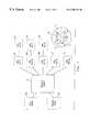
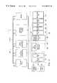
- FIG. 1Depicts a plurality of 3D data points (a cloud of points) and a texture map file which the computer system of the present invention uses to generate meshes of different resolutions and object displays.
- FIG. 2 aDepicts a plurality of data points which comprises a set of 3D x, Y, Z coordinates that describe the object.
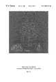
- FIG. 2 bDepicts exemplary texture map data.
- FIG. 2 cDepicts a mesh model of comparatively low resolution created according to the teachings of the present invention (depicted for exemplary purposes in gray scale).
- FIG. 2 dDepicts a middle resolution mesh model of a 3D object created according to the teachings of the present invention (depicted for exemplary purposes in gray scale).
- FIG. 2 eDepicts a high resolution mesh model of a 3D object created according to the teachings of the present invention (depicted for exemplary purposes in gray scale).
- FIG. 2 fDepicts a mesh of lower resolution than FIG. 2 e created through a down resolution process.
- FIG. 2 gDepicts a mesh of lower resolution than FIG. 2 f created through a down resolution process.
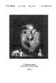
- FIG. 2 hDepicts an image of the object rendered from the information of the low resolution mesh model of FIG. 2 c.
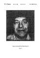
- FIGS. 2 i-jDepicts images of the object rendered from information of the mesh models of FIGS. 2 d and 2 e.
- FIG. 3Depicts an overview of basic programmed elements and data structures used to implement an exemplary meshing system with up resolution/down resolution capabilities.
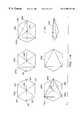
- FIG. 4Depicts a normal calculation for a data point inserted into a mesh structure.
- FIG. 5Depicts an exemplary ordering of points of a mesh face and shows the relationship of those points to neighboring faces according to the present invention.
- FIG. 6Depicts an exemplary process flow for an exemplary build and wrap function which creates a set of space and texture coordinate values according to the present invention.
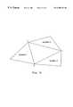
- FIG. 7Depicts an exemplary mesh triangle overlaid on a set of texture map pixel values and shows how a 3D X, Y, Z value is created for a pixel by interpolation.
- FIG. 8Depicts an exemplary process flow for the process of rasterization, which creates X,Y,Z values for provided texture map coordinates.
- FIG. 9Depicts the basic process steps of the up resolution function of the present invention.
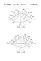
- FIG. 10 aDepicts a cloud of data points fitted to a sphere.
- FIG. 10 bDepicts a second cloud of data points fitted to a plane.
- FIG. 10 cDepicts a tetrahedron constructed for a cloud of data points where the initial reference object is a sphere.
- FIG. 10 dDepicts an initial mesh constructed from Steiner points where the initial reference object is a plane.
- FIG. 11Depicts a mesh triangle and an associated mesh point for purposes of distance calculations.
- FIG. 12Depicts an incremental insert procedure for the up resolution function of the present invention.
- FIG. 13Depicts a data point being inserted into a mesh triangle.
- FIG. 14 aDepicts two triangles which will be evaluated for flipping by data dependent principles.
- FIG. 14 bDepicts the triangle of FIG. 14 a after the flip.
- FIG. 15Depicts an exemplary process flow for a data dependent edge check.
- FIG. 16Depicts a sequence of flips which might be taken to transform a mesh into a configuration for data point removal.
- FIG. 17Depicts a hypothetical point removal in which a distance value for the point is computed using a normal vector.
- FIG. 18Depicts a hypothetical point removal in which a distance value for the point is computed using normal vectors of the point to be deleted and the points that have previously been deleted.
- FIG. 19Depicts an exemplary process flow for a point removal flipping procedure which minimizes structural deviations in the mesh.
- FIG. 20Depicts the calculation of the error value for a point removal flipping procedure which preserves Delaunayian optimality.
- FIG. 21Depicts the calculation of the error value for a point removal flipping procedure which preserves data dependent optimality using normals.
- FIG. 22Depicts an exemplary process flow for a down resolution mesh construction process.
- FIG. 23 aDepicts a digitized photographic image.
- FIG. 23 bDepicts a mesh model of a photographic image.
- FIG. 24Depicts an exemplary process flow for creating mesh models from a 2D bitmap.
- Appendix IContains color copies of the meshes depicted in FIGS. 2 a-j.
- FIG. 1depicts a plurality of data points 2 a (which can be a “cloud of points” or a mesh with some connectivity information) and a texture map file 2 b , which the computer system 3 of the present invention uses to build a series of meshes (e.g., meshes 2 c - 2 g ).
- the plurality of data points 2 aare spatial X, Y, Z 3D coordinates that describe the physical contours of the object.
- the texture map file 2 bis a set of one or more bitmaps or 2D arrangements of pixel elements which represent digitized 2D “snapshots” of the object.
- the X, Y, Z Coordinates in the plurality of data pointslink to a specific coordinate in the texture map file through a reference to a texture space u, v position.
- the plurality of data points 2 awill also have connectivity or other additional data associated with it such as normal data as described below.
- the plurality of data points 2 a and the texture map file 2 bcan be collected in any number of ways, such as by user input or laser scanning.
- a system and method for collecting data points and texture map data through scanningis described in pending U.S. patent application Ser. No. 08/620,684, filed on Mar. 21, 1996 and entitled “System and Method for Rapid Shape Digitization and Adaptive Mesh Generation,” and in pending U.S. patent application Ser. No. 08/679,498 filed on Jul. 12, 1996 and entitled, “Portable 3D Scanning System and Method for Rapid Shape Digitizing and Adaptive Shape Generation.” Those applications are expressly incorporated herein by reference.
- FIG. 2 ashows an exemplary plurality of data points 2 a which comprise a set of 3D X, Y, Z coordinates that describe an object.
- FIG. 2 bdepicts exemplary texture data from the texture map file 2 b (which could be in color but is shown in gray scale) which contains bitmap images of the object with each pixel having a color arrangement such as a 3 byte (24 bit) R, G, B color assignment.
- the computer system 3processes the incoming spatial (X, Y, Z) and texture map data by first creating an initial spatial model of the object (not shown) and then in a “rasterization” process, combining the spatial and texture map data by “wrapping” the texture map data onto the initial spatial model to form a set of multi-dimensional/multi-axis coordinates.
- those complex data pointsare the 6D (X, Y, Z, R, G, B) coordinates mentioned above.
- the computer system 3then constructs a mesh model having dynamic resolution capabilities from the 6D data points created above. For these constructions, the system executes either a “down resolution” construction process (which first creates an initial dense mesh which is simplified through data point removals) or an “up resolution” construction process (which starts from basic simple mesh and adds points to increase the mesh's detail).
- the computer system 3outputs the mesh data structures in different resolutions (represented by meshes 2 c - 2 g ) which can be displayed and manipulated.
- the system of the present inventioncan build meshes having different resolutions of mesh, beginning with 2 c .
- FIG. 2 cdepicts mesh 2 c , a mesh of comparatively low resolution illustrating mesh construction after the addition of just a few hundred 6D data points.
- FIG. 2 ddepicts mesh 2 d , a mesh of middle resolution after the addition of more 6D data points.
- FIG. 2 edepicts mesh 2 e , a mesh of highest resolution.
- the systemadds detail to the mesh incrementally through the insertion of points.
- Each mesh incrementally generated from 2 c - 2 ehas more and more data points, until, as shown in mesh 2 e (FIG. 2 e ) all but a few data points of insignificant detail have been added to the mesh.
- the computer system 3selects 6D data points to add to the mesh according to a technique which determines the point's significance in terms of both spatial and color data. If a 6D data point is significant because it adds spatial characteristics, the system will add it to the mesh. In addition, if a data point adds significant texture, such as important color details, the system will add it to the mesh as well.
- mesh 2 fdepicts a mesh of lower resolution than mesh 2 e .
- Mesh 2 greturns the mesh to the low resolution quality, similar to mesh 2 c .
- FIGS. 2 f - 2 gshow exemplary depictions of such meshes.
- the present inventionmaintains a specific history of the additions and subtractions of points to and from the mesh, the deletion and addition of the sequence of points can be monitored by the system and that history can be stored in a compact, coded sequence for rapid up and down resolution mesh construction at runtime.
- the present inventionalso provides a “down resolution” construction format, where all 6D points are combined into a single dense mesh which is then simplified through data point removals.
- the systemstores the sequence of point removals so that at runtime the resulting simplified mesh can be rapidly “up resolutioned” and “down resolutioned” like the meshes created by the “up resolution” construction format.
- the systemcreates an irregular triangulated mesh as shown in insert 2 k in FIG. 1 .
- the edges of the mesh faces, e.g., edges 4 , 6 and 8 in mesh 2 kcreate geometrically shaped, planar faces, such as triangle 10 .
- the vertices of any triangle, e.g., points 12 , 14 and 16are 6D data points which the system adds through incremental input in the “up resolution” construction process or deletes in the “down resolution” construction process.
- Each triangle in the meshe.g., triangle 10
- the faces, edges and verticescan be associated with other information concerning the object such as normal data and color/texture information.
- a mesh model structurecontains spatial and texture information to output photorealistic displays of the object.
- Each model generated by the systemcan be used to output depictions or reproductions of the object, with the resolution of the depiction varying according to the resolution of the mesh.
- FIG. 2 hdepicts in gray scale an image generated with the relatively low resolution mesh of FIG. 2 c .
- FIG. 2 idepicts an image generated with the middle resolution mesh 2 d and
- FIG. 2 jdepicts an image generated with the high resolution mesh of FIG. 2 e .
- each of the data points in the meshcarry color as well as spatial information, it is possible to generate an image of the object using only the mesh model.
- Algorithms for renderingsuch as rasterization processes using Gouraud or Phong shading techniques, render mesh triangles in gradient color based on the color values contained in the 6D vertex coordinates of each face, so that a very life-like image of the object can be generated.
- the computer system 3employs a computer (not shown) comprising a central processing unit (“CPU” or “processor”) to accept input data, manipulate the data and create data structures related to the model building.
- the processoris coupled to one or more memories which store the data, data structures and programmed elements.
- the processoris coupled to graphics hardware such as a VGA card and could be coupled to more specialized graphics hardware (such as a rendering engine which can execute polygonal shading by linear or bilinear interpolation such as Gouraud shading).
- the computer system 3also comprises a display device and input devices like a keyboard and a mouse which are coupled to the processor.
- the computer manufactured by Silicon Graphics Incorporated and sold under the product name Indigo2TMis suitable to implement the system of the present invention.
- the Indigo2TM computerhas a R4400, 250 MHZ processor, 32 Mb of primary RAM storage and includes hardware capable of performing the needed rendering.
- more powerful computerssuch as the OCTANETM or O 2 TM computers using single or dual MIPS R5000 and R10000 CPU's, which are also manufactured by Silicon Graphics, can also be used.
- generic PC computersthat have an Intel Pentium host processor having a graphics operating system (such as Microsoft Windows), of approximately 16 Mb of RAM, and graphics processing capabilities that support rendering such as Gouraud shading, are suitable for storing mesh constructions and outputting displays.
- the readeris referred to information and references listed at the following websites:
- a set of programmed elements stored in memoryprovides instructions that the processor executes to perform the operations of the computer system 3 .
- programmed elementsare written in the C++ programming language.
- the C++ Programming LanguageBjarne Stroustrup, Addison Wesley Publishing Co., 1991; C++ Inside & Out , Bruce Eckel, Osborne McGraw-Hill, 1993.
- FIG. 3depicts an overview of the basic program elements and data structures used to implement the exemplary meshing functions for the computer system 3 .
- a build and wrap function 130merges the 3D X, Y, Z plurality of data points 2 a (the cloud of points) and the texture map file 2 b to create the set of 6D (X, Y, Z, R, G, B,) values in a two-step process.
- the processoruses the build and wrap function 130 to construct an initial spatial mesh (if one has not been provided) and then, in a “rasterization” process, wraps the set of points from the texture map file around the mesh to create a set of 6D coordinates.
- the computer system 3will use the points in a pre-runtime process to build a mesh structure that has dynamic resolution capabilities following either an “up resolution” construction process 131 or a “down resolution” construction process 132 :
- the systembegins with an initial mesh of just a few points and then builds a more complex 6D wireframe mesh point by point through a selection process where it chooses the order of points to insert.
- the systemchooses from all the available unmeshed points the next most significant point to add in terms of color or spatial detail.
- the computer system 3can output or save the mesh, or display a depiction of the object by sending information from the mesh to a rendering function 134 .
- the rendering function 134prepares the mesh for display.
- the systemfirst builds a mesh to its fullest density using all the created 6D points and then simplifies it by removing points in successive point deletion steps. In determining which next point to remove from the mesh, the down resolution processing function 132 evaluates the remaining points to locate the data point which adds the least amount of detail to the mesh in terms of color or spatial detail. The procedure for point selection is described in further detail below.
- the meshes created through the up resolution construction process 131could be output and rendered at any point during the point insertion process
- the meshes created through the sequence of point removal processes in down resolution constructioncan also be output or saved; in addition, the system can display images of objects using meshes of various “down resolution” detail.
- the rendering function 134prepares these meshes for display.
- the present inventionuses a selection process to choose what next data point to add or remove.
- the decision to add any 6D data point into the meshis based on a determination of whether that point, of all the remaining unmeshed points, is the “most significant” to the mesh structure in terms of adding spatial, color or other detail.
- the decision to remove any 6D data point from the meshis based on a determination of whether that point of all the remaining points in the mesh is the “least significant” to the mesh structure in terms of adding spatial, color or other detail.
- the system and method of the present inventionperforms a series of steps (as will be described in further detail below) to calculate a “distance” value which represents significance.
- the present inventioncan calculate significance by two possible methods:
- FIG. 4depicts a normal 155 for the point 156 which has been constructed from the normals 157 - 161 of the triangles 162 - 166 .
- the use of normals for the determination of significancewould be most practical if the data points came to the system with their normal vectors already associated.
- the initial set of pointsconsists of a random “cloud of points” with no associated connectivity information and no normal data associated with them, it may be too time consuming to execute a point insertion process in up resolution construction using the normal distance calculation as the determinant of significance.
- the processorcould use the normal distance calculation procedures outlined below to create an up resolution procedure that determines significance by normal distance.
- a system for calculating normalsis presented as part of its process of preparing a mesh for down resolution construction.
- the processorcan (before down resolution point removal begins) calculate a normal vector for each data point in this dense mesh. Because the mesh is in its most dense and detailed state at the beginning of the down resolution process, the normal vectors provide a good indication of the surface topology for the mesh. Thus, in a down resolution process, normals can be used easily in the selection process that determines what next point to remove.
- the systemcan compare the normal of the remaining face at the location of the point removal against both: 1) the normal for the data point removed and/or 2) the normals for all of the previous points removed that are projected into the mesh triangle being compared.
- the present inventionenables the determination of significance to be based upon the topology of the original dense mesh—i.e. the reference which most closely approximates the original object. In the exemplary embodiment this procedure is described in detail below.
- the present inventioncan also be configured to recompute normal vectors for each data point remaining in the mesh as the mesh changes in the down resolution mesh construction process 132 .
- the systemcan recompute the normal vectors for each remaining point.
- using “dynamic normal calculations,” the systemevaluates both the current normal vector for the point under consideration as well as normals for points that have been removed from the mesh that were associated with the triangle in question. This determination of significance allows the system to create a smooth transition between point removals in the mesh.
- each of those processesexecute a checking procedure which examines the connectivity of the mesh and insures that the mesh maintains an optimal structure.
- checking of the mesh structure in the up resolution processcan be accomplished by a number of checking procedures which optimizes by:
- Delaunayian and data dependent checking proceduresflip edges to change the connectivity of the edges and data points as necessary to achieve better structural quality for each mesh.
- Delaunay triangulation optimality principleshelp to insure that the irregular triangulated mesh maintains a construction of evenly proportioned triangles.
- Delaunayian triangulation principlesteach that a circumcircle defined by the vertices of a triangle will not contain another data point of the mesh. Delaunay triangulation is recognized as one type of optimization for mesh construction which insures homogeneous, regular triangles.
- Data dependent optimization techniquesuse the information available about the shape of the object and will adjust the edges of the mesh so that they are aligned with the contours of the object.
- Data dependent optimization techniquesevaluate object related data such as:
- Data dependent edge checking routinescan be used in both the up resolution construction process 131 and the down resolution construction process 132 . Again, as normal vectors are more easily and readily compatible in a down resolution construction process, data dependent checking would more ordinarily be performed in a down resolution construction process. However, normal-based data dependent checking could be used in up resolution mesh construction, especially if the data points came to the mesh construction system with associated normal information.
- the systemalso tracks the history of steps taken for those point insertions or removals, including the checking steps taken to achieve the optimal quality characteristics (such as by Delaunay or data dependent optimality principles). Both the up resolution construction process 131 and the down resolution construction process 132 store information concerning those steps—the history data.
- the history datapermit the up resolution and down resolution construction procedures 131 and 132 to create meshes with dynamic resolution capabilities.
- the processoruses the history data to undo or reverse a point insertion by deleting the point or reversing a point deletion by inserting the point.
- the system of the present inventionprovides in FIG. 3 an up/down resolution toggle function 136 to dynamically adjust the resolution quality of any mesh using the values stored in mesh's history list data.
- the up/down resolution toggle function 136follows back and forth over the list of inserted or deleted points and the information in the history list (described below) to execute rapid resolution adjustments.
- the up/down resolution toggle function 136 in the exemplary embodimentalso functions with the rendering function 134 to output displays of meshes at any given resolution.
- an interface 138provides a user or application interface for the mesh construction, toggle and display functions ( 131 , 132 , 134 and 136 ).
- each of the programmed elements for up resolution or down resolution processing 130 - 136will access a number of data structures 140 .
- data structures 140Although many different data structures are suitable, the following are exemplary for the data structures 140 :
- the data structure for the 6D data point list 142contains two arrays: an X,Y,Z array ( 141 ), which contains spatial coordinates, and an R,G,B array ( 143 ) which contains color coordinates.
- Each array ( 141 and 143 )is dynamically allocated and sized to the number of data points created through the wrapping process (build and wrap 130 ).
- each X, Y, Z array slothas three floating point numbers (e.g., 32 bits each) allocated to it.
- the R, G, B arrayhas 24 bit locations in each slot (8 bits per color).
- Each X, Y, Z valueis combined or linked to a specific R, G, B value.
- R, G, B color valuecorresponding to that point at the same location in the R, G, B array 143 .
- R, G and Bcolor or texture values can be represented in other ways, such as by black/white/gray, cyan-magenta-yellow (CMY), hue/saturation/intensity (HSI), y-signal, u-signal and v-signal (YUV) or other color space systems, and the R, G, B array 143 in the 6D data point list 142 would contain data slots for such other representations.
- the 6D data point listscould also be stored using a tree structure in which the X, Y, Z and R, G, B, arrays are created not as corresponding lists but as two corresponding trees, where for each node in the X, Y, Z array 141 there is a corresponding node in the R, G, B array 143 .
- the present inventionalso provides a data structure to store other “per-vertex” information, such as normal information.
- normal informationcan either be included with the data point information or derived from connectivity information.
- the systemstores the normal vectors associated with each set of X, Y, Z, R, G, B coordinates in a normal list 149 .
- the normal list 149is a dynamically allocated array corresponding to the number of available 6D data points. For each entry in the X, Y, Z array 141 there will be a corresponding entry in the normal list 149 into which the system can write computed normal values, such as three 32 bit floating point numbers.
- the mesh data structure 144maintains information for each mesh face, its vertices, edges and neighboring faces.
- the mesh data structure 144contains a plurality of face records (e.g., 145 ) (such as a linked list) each of which contains information concerning a particular geometric mesh face.
- the set of face recordstogether form the data structure for the mesh model.
- the systemrepresents a face record in an irregular, triangulated mesh as follows:
- FACENEIGHBORS: Neighbor #0, Neighbor #1, Neighbor #2 (Array of 3 pointers to other FACE records)
- VERTICESVertex #0, Vertex #1, Vertex #2 (An index array containing the slot location references to each of the three 6D (X, Y, Z, R, G, B) coordinates on the data point list 142)
- FLAGS Indicatorsspecifying properties of a face, such as its position on a triangulation ASSOCIATED POINT Index references to locations on the 6D data INDICES point lists for each data point that is “associated with the face of any given construction” (e.g., an index to the first element in a linked list of indices of vertices associated with a face)
- the data element NEIGHBORSconsists of an array of three pointers, each pointing to a FACE record for a neighboring (adjacent) face in the mesh.
- the data element VERTICESis an index array that references a location on the 6D data point list 142 (and the 6D (X, Y, Z, R, G, B), point information) for each of the triangles' vertices.
- the systemstores data concerning each vertex and neighbor in the face records of the mesh data structure 144 according to a rigid ordering system.
- the systemorders the points of a triangle in a counterclockwise sequence: 0, 1 and 2. It is understood that the vertices could also be numbered in clockwise order or ordered by another fixed ordering system.
- the systemorders the neighboring triangles in the same counterclockwise order to relate them to the vertices.
- the systemindexes neighbor #0 to be directly opposite vertex 0.
- Neighbor #1is directly opposite vertex #1.
- Neighbor #2is directly opposite vertex #2.
- the present inventionprovides a system to maintain this ordering during point insertion and deletion and during any checking procedure to insure the optimality of the mesh such as a check to maintain Delaunayian or data dependent optimality.
- This systemuses the ordering of the vertices and neighbors (as is described in further detail below) to complete the needed mesh reconfigurations.
- the associated point indices of the face recordscontain the 6D data point array locations for each 6D data point that must be associated with the triangle, for purposes of calculating distance values—based on geometric distance or normal distance—or for optimal construction checking.
- the facesare altered, such as by point insertions or point deletions, the data points associated with a particular face change. As changes to the faces occur, the system of the present invention will rearrange the set of associated data points for each altered face.
- the vertex list records in the face records (e.g. 145 ) of the mesh data structure 144provide a link from face to data point for each of the vertices in the mesh.
- the presented inventionprovides in the exemplary embodiment a fact list 148 .
- the face listis an array structure containing points whose index entries correspond to the entries in the 6D data point list 142 .
- the present inventionuses a selection process to choose what next data point to add in the up resolution construction process 131 or remove in the down resolution construction process 132 .
- the decision to add any 6D data point to the mesh in up resolution constructionis based on a determination of whether that point, of all the remaining unmeshed points, is the “most significant” to the mesh structure in terms of adding spatial, color or other detail.
- the decision to remove any 6D data point from any mesh in down resolution constructionis based on a determination of whether that point of all the remaining points in the mesh is the “least significant” to the mesh structure in terms of adding spatial, color or other detail.
- the system and method of the present inventionperforms a series of steps (as will be described in further detail below) to calculate either: “geometric/color distance” or the normal distance.
- the distance valueis added to a distance list 146 .
- the distance list 146contains the calculated distance of each unmeshed data point as it exists in from the relevant face on the existing mesh.
- the distance list 146contains the calculated distance value for each meshed point remaining in the mesh.
- the processorwill then store on the distance list 146 information including: (i) the calculated distance value; (ii) an index reference to the location on the 6D data point list containing the 6D (X, Y, Z, R, G, B) coordinates for the point; and (iii) a pointer reference to the particular face record in the mesh data structure 144 for the associated face.
- the distance value for the pointis set to 0 (or its entry can be deleted from the list).
- the computer system 3organizes the entries in the distance list 146 by a technique that always returns the 6D data point having the largest distance from its associated face in an up resolution construction or the point having the smallest distance in down resolution construction.
- the computer science technique of “heaping”is one organizational system suitable for storing distance values on the distance list 146 and quickly returning either the largest or smallest distance value.
- a heaporganizes a list into a tree structure where each parent node has a distance value that is larger than each of its children.
- the processormaintains the largest distance value at the top of the tree structure (e.g., position 147 ) along with a pointer to its vertex in 6D data point list 142 .
- the smallest distance valueremains at the top of the heap.
- a set of heap manager functions 147enable the processor to add and delete values from the heap.
- the computer system 3When the computer system 3 adds a 6D data point to the mesh in the up resolution construction 131 or removes a point in down resolution construction 132 , it will also write indications of the insertion process on an insert list 150 and a history list 152 .
- the insert list 150 and the history list 152are data structures that permit the system of the present invention to perform rapid up/down resolution toggling at run-time. These lists provide data structures used to track the sequence of point additions and other changes that occur so that the up resolution and down resolution construction processes can be rapidly reversed and replicated.
- the insert list 150contains locations which store a copy of the 6D X, Y, Z and R, G, B coordinates of the point which the processor has deleted or inserted. These values have been copied from the arrays in the 6D data point list 142 .
- the insert list 150also contains a reference to a face record in the mesh data structure into which the data point was inserted or from which it was removed.
- the history list 152contains a sequence of compact indicators which provide information so that the system can reverse steps of the optimality checking that occurred during point insertion or point removal.
- both the insert list 150 and the history list 152comprise stack structures where the processor enters data in an order which can be quickly reversed.
- the insert list and history listcan be maintained as separate lists or they can be compared as one single list.
- the processorloads the insert list 150 and history list 152 in LIFO (last in first out) order. As the point inserted earlier in up resolution construction are more significant than the points added later, the earlier points should be removed last in any down resolution toggling.
- the systemconstructs the insert list 150 and the history list 152 in the opposite way. As points are removed from the mesh during down resolution the processor loads the insert list 150 and history list 152 stacks in FIFO (first in first out) order. Because the deletion processor removes points of less significance earlier and more significance later, in rapid up resolution toggling the processor will seek to reinsert the most important points first.
- the information contained in the insert list 150 and history list 152could be maintained in a vertex tree structure instead of a stack structure.
- the vertex tree structureswould support view-dependent multi-resolution.
- the system of the present inventioncan rapidly increase or decrease detail (and provide “dynamic resolution” capabilities using those lists).
- the systemcan then increase or decrease resolution from the mesh simply by following in reverse order the stacks of the insert/delete list 150 and the history list 152 .
- the computer system 3can also regenerate meshes to specific levels of detail by following the sequences of point removals and reconfiguration already indicated on the insert list 150 and the history list 152 .
- the computer system 3will first build the insert list 150 and history list 152 in a pre-routine time process following either the up resolution or down resolution process, adding or deleting points in a first pass to the full capacity of the mesh and then, in subsequent mesh model generation processes, simply follow those lists to rapidly regenerate meshes to any level of detail, such as to a user-specified tolerance.
- the computer system 3employs a recalculate list 154 to list face records whose 6D data point values will need reevaluation.
- the recalculate list 154operates as a stack (maintained in LIFO order) containing pointers to entries in the 6D data point list 142 .
- the data structures 140 described aboveare used with the basic program elements to perform system functions. It is understood that the data structures 140 are exemplary; the teachings of the present invention can also be implemented using other data structure configurations. In addition to the elements described above, there are also a number of task performing subroutines and functions which are further described below.
- the computer system 3uses the build and wrap function 130 in an exemplary embodiment to construct a set of 6D (X, Y, Z, R, G, B) data points.
- the process as depicted in FIG. 6consists of two steps: first is a step (step 170 ) of building (if necessary) an initial wire frame mesh (which can be one which uses only the 3D spatial coordinates); second is a step (Step 172 ) of “wrapping” the pixel coordinates of the texture map around the 3D wire frame mesh and constructing 6D (X, Y, Z, R, G, B) coordinates for each of the available pixels through a rasterization process.
- Step 170the step of generating an initial spatial mesh, requires the processor to create a wire frame mesh using only the 3D X, Y, Z spatial values.
- Each X, Y, Z data point in the plurality of data points 2 acomes with a reference (—a u, v reference) to a corresponding pixel point in the texture map file 2 b .
- the X, Y, Z and R, G, B values for these data pointscan also be loaded into the 6D data point list.
- the initial spatial meshcan be stored in a temporary data structure.
- the rasterization processcan be configured in the exemplary embodiment to generate either a full compliment of X, Y, Z coordinates for every R, G, B texture map coordinate.
- the rasterization processcan be configured to make a more selective pass through the texture map coordinates and create X, Y, Z, coordinates only for certain R, G, B texture map values. Because full rasterizations can potentially generate hundreds of thousands of new 6D data points, it may not be advantageous to introduce them all into the mesh construction.
- the up resolution construction process 131it may not pose a problem to first generate a full compliment of X, Y, Z values for each R, G, B value because the up resolution mesh construction process itself can serve to discriminate and select which points it would choose to add into the mesh.
- the processing hardwareis available, the full complement of point values could be generated even for a down resolution process.
- FIG. 7depicts an exemplary pixel 250 from an area in a texture map file which is limited to a mesh triangle and shows how the processor can determine a 3D X, Y, Z value for the pixel.
- Pixel 250is bounded by vertices of a triangle having known X, Y, Z values: i.e., point A (point 252 ); B (point 254 ); and C (point 256 ).
- Pixel point 250falls along a scan line of pixels, identified as line P 258 .
- Line P 258intersects two edges of the triangle edge AB 260 and edge AC 262 .
- the processorcan determine 3D equations for edges AB 260 and AC 262 and correspondingly, an equation for line P 258 based on intersections with the AB/AC edges. From those determinations, the processor can calculate 3D X, Y, Z values for pixel 250 .
- FIG. 8depicts an exemplary process flow for generating points according to a rasterization process.
- the process of FIG. 8generates a full set of 6D (X, Y, Z, R, G, B) values from the available spatial and texture data.
- the processorbegins a loop that will rasterize X, Y, Z coordinate values for the associated texture map pixels with a mesh triangle.
- the processoraccesses the triangle information from an initial mesh data structure created by the process in step 170 .
- the processorgets the next available triangle.
- the processorlocates the u, v links that each vertex in the mesh triangle has as a reference to a corresponding point in the texture map file.
- the processoruses the (u, v) links that each vertex in the mesh triangle has to a pixel value in the texture map file. If the spatial and object modeling data has been obtained from a scanning system, that data was obtained simultaneously from the same camera and the X,Y values of the 3D spatial coordinates of each vertex will match the u, v 2D coordinates of a designated bitmap image in the texture map file 2 b.
- step 206the processor determines from the u, v texture map coordinate values the minimum and maximum texture map coordinates vmax and vmin for the three triangle vertices.
- each v scan linewill contain R, G, B coordinate values for each u.
- the rasterization processwill loop through each v scan line creating X Y, Z values for the corresponding R, G, B values.
- the umin and umax valuesare used for rasterizing those values determined for later processing.
- step 208the processor loops to calculate, for each edge of the texture map triangle found by the three u, v coordinate values, the change in X, Y, Z for each change in the v value and the change in X, Y, Z for each change in the u value.
- the processorfor each edge, the processor, in step 210 , computes:
- the processoralso arranges the edges to identify the two edges that have the vmin value. It is from that part of the triangle that the rasterization process will begin.
- step 212the processor begins a set of processes to set the edge values between which the processor will compare the X, Y, Z values. For each v line of pixels, the processor will need to establish a right and left u position and a corresponding X, Y, Z value. As the v scan lines change the X, Y, Z values will change following the dv values. Along each u scan line the X, Y, Z values will change along the du values. In step 212 , the processor sets the right and left edge points at the outset to be the shared endpoint of the edges (right and left) which share the vmin value. Next, the processor proceeds to step 214 to establish a stepping factor for each of the variables based on the delta values, dXdv, dYdv, dZdv and dZdv for each scan line step through the pixel values.
- step 216the processor begins a loop to process the pixels in the scan line.
- the loopprocesses each scan line from vmin to vmax.
- the first stepis to begin a check on the edges which use the vmin value to see if they have not run out (step 218 ). If either the right or left edge has run its length, and the v scan line is beyond it, the processor will swap the third edge with that edge.
- step 220the processor establishes the boundary of right and left edges along the v scan line and the X, Y, Z values that are associated with it.
- the stepuses the dv values to establish a left edge u point and a right edge u point and the associated X, Y, Z values.
- the processorcan now generate in X, Y, Z value for each texture map coordinate R, G, B value.
- FIG. 8presents a loop which processes X, Y, Z values for each u position moving from the left to the right along the scan line. For each u increment, the processor creates X, Y, Z values and loads them into the 6D data point list 142 using the dXdu, dYdu and dZdu delta values (step 224 ).
- step 226the processor loops to step 222 and continues processing X, Y, Z values for each u position in the current scan line.
- the processorloops in step 228 to step 216 to process another scan line.
- the processorloops in step 230 to step 200 and processes the next triangle until all triangles have been processed.
- the rasterization process described in FIG. 8generates one X Y, Z spatial coordinate for each texture map coordinate.
- the procedurefunctions very much like the procedure outlined in FIG. 8, except that in addition to processing delta values for dX, dY and dZ, the process would also process delta values for dR, dG and dB using the R, G, B values from the texture map that were associated with the original three mesh data points.
- the rasterized R, G, Bcould be compared against the actual R, G, B values in the texture map.
- the processorwould generate a X, Y, Z value and create a 6D data point. If the difference fell below a threshold, it would not.
- a mesh with dynamic resolution capabilitiescan be created with the above-generated 6D data points using either an up resolution construction process 131 or a down resolution construction process 132 .
- the processorexecutes the up resolution construction process 131 (FIG. 3) to build a mesh model point by point with ever increasing resolution of detail.
- the up resolution function 131has two basic steps as set forth in FIG. 9 . First, the processor creates an initial mesh structure (in step 270 ) and second, the processor incrementally adds 6D data points to that mesh structure following a selection process that assesses the significance of each unmeshed data point (in step 272 ).
- the processor in the up resolution construction processbuilds an initial mesh structure with reference to an initial object, such as a plane or sphere, which is selected in the exemplary embodiment by user-specification.
- an initial objectsuch as a plane or sphere
- the highest resolution meshitself may be used as the reference object.
- the original meshverices, connectivity and normals
- the processorprovides functions to assist in the selection of the initial reference object.
- a usercan select an equation for a plane that exists above, below or within the set of 6D data points, depending on user preference.
- the usertypically will select an equation for a unit sphere at a center point location within the mass of the 6D data points thus providing separation between back, front, left, right, top and bottom.
- Many different techniquesare currently available and can be used to determine “proximity to” the initial reference object. For example, the processor could determine an equation distance from an initial reference plane by a minimum sum of squares method.
- the processorcan determine the sphere's equation by a fitting function which determines center of mass.
- FIG. 10 adepicts a sphere fitted to a cloud of data points fitted to a sphere.
- FIG. 10 bdepicts a plane fitted to a cloud of data points.
- the processoruses the 3D X, Y, Z values of the 6D coordinates in the fitting equations. Although it would be possible to include color data as a factor in determining the initial reference object, the exemplary system does not include such calculations.
- the processorconstructs an initial mesh, the structure of which depends on whether a sphere, plane, or other object was chosen as the initial reference object. If a sphere is selected as the initial reference object, the processor constructs the initial mesh in the form of a tetrahedron. Such a tetrahedron is depicted in FIG. 10 c .
- the processorbuilds mesh faces and adds them to the mesh data structure based on the selection of four data points from the cloud of 6D data points. In an exemplary embodiment, the processor executes a procedure to select four points from the group which most closely determine a tetrahedron of equilateral triangles. However, in alternative embodiments any initial 3 or 4 points from the set of 6D data points, even randomly selected points, will be sufficient for the initial mesh.
- the processoruses these points to build face records and places the face records in the mesh data structure 144 .
- the processorcreates an initial mesh in the form of either a single triangle or a quadrilateral (constructed from two triangles).
- the points for this initial meshwill be points that exist on the reference plane itself as “Steiner” points.
- the processorselects the initial points so that the area bounded by the initial mesh on the initial reference plane includes all of the 6D data points as projected on that plane. A representation of such an initial mesh face is set forth in FIG. 10 d.
- the processorIn selecting the points of the initial mesh faces in the planar example, the processor must also designate a color value for each initial vertex selected, as the present invention incorporates both spatial and texture data into the construction.
- the selection criteriaincorporate color values as one selection determinant.
- the processorwill select black as the initial color for the mesh construction, and 6D points of light color will contrast and will be added by the selection procedure (as will be described below).
- other colorscan be used in the initial color setting, such as white, neutral colors such as a gray (when the 6D pixel values have both light and dark settings), and vibrant colors such as red.
- the highest resolution mesh itselfmay be used as the reference object. This approach is most appropriate for surfaces that are too complex to be projected onto a plane or sphere and whose connectivity is given before up resolution construction.
- step 272follows the principle that mesh points can be ordered according to their significance in describing the basic shape and color features of the object. By selecting those points which are most descriptive in terms of color and shape from the list of points, the computer system 3 of the present invention can fully approximate, describe and reproduce both the basic shape contours and color details of an object with relatively few selected points. As more detail is required, a system following the up resolution selection principle can add more details by simply adding the next most significant points. Using the selection process of the present invention, it is possible to generate a very low resolution mesh model of an object which contains enough detail to create an acceptable image of the object on most displays. For example, a set of 6D data points obtained from a laser scan of a person's face can be typically simplified from an initial set of 100,000 data points to a mesh of a few thousand data points which describe the contours and color details with good resolution.
- the procedureoperates by up resolution—incrementally adding 6D points of detail from the mesh until the mesh meets the resolution set by the user's specification, or until the mesh is created to the highest density of resolution.
- a reference to the pointis added to the insert list 150 (FIG. 3 )—the LIFO-ordered stack which tracks the sequence of point additions.
- the insert listmay also be structured as a tree to provide “view-dependent” multi-resolution).
- the addition of a pointalso causes changes to the mesh structure as is described below.
- the sequence of changes that occurs due to point additionis maintained in the history list 152 (FIG. 3, which is also maintained as a LIFO stack or tree).
- the insertion and history lists ( 150 and 152 )contain the full sequence of point additions from initial mesh to highest resolution mesh, it is possible, as is described below, to follow the insert list 150 and the history list 152 to rapidly generate a mesh model of the object to any level of detail.
- determination of a 6D data point's significance in the up resolution construction processdepends upon how much spatial or color detail a 6D data point would add to the mesh's current configuration.
- the meshis in the form of a plane or a tetrahedron.
- the selection procedureseeks to add, at the earliest stage, the points which are the most significant in describing the basic shape and color details of the object and, thereafter to continue adding points where each next point is the most significant point from the remaining unmeshed points in terms of adding spatial or color significance.
- the processor 3 in step 272calculates a “distance” value for each unmeshed 6D data point and selects the next point to add based on this “distance” value.
- Pending U.S. patent application Ser. No. 08/730,980 and pending U.S. patent application Ser. No. 08/730,979, both referenced above and incorporated by reference herein,describe systems and methods for calculating a distance value that a data point value would have in relation to a mesh using 3D spatial coordinates. The present invention goes beyond that basic teaching and permits a distance value to be calculated based on 6D coordinates, using both the X, Y, Z and R, G, B values of each unmeshed data point.
- FIG. 11depicts triangle 300 formed as part of a mesh construction and a 6D data point 302 which has yet to be incorporated into the mesh.
- the initial reference object for the meshis sphere 303 .
- a projection of triangle 300(triangle 304 ) appears on sphere 303 .
- 6D data point 302can be associated with triangle 300 when the point lies within the bounds of the triangle.
- a line 308can be drawn from the center point of triangle 300 (point 310 ) to 6D data point 302 and it can be shown that the projection of that line segment (projection 312 ) on sphere 303 does not intersect any edge of the projected triangle 304 .
- the system of the present inventioncan calculate the spatial distance 6D data point 302 has in relation to triangle 300 .
- the three vertices A, B, and C of triangle 300form a plane, and the distance of point 302 from that plane can be defined Euclideanly in terms of unit vector n ( 314 ) normal to the plane as follows:
- n 1 through n mare the respective normals of the points associated with the face, whether because the point is a vertex of the face or because the point was associated to the face in the down resolution process.
- Color deviationmay be measured non-Euclideanly.
- the deviationis set at:
- L Ris the luminance or phosphor value of the color red.
- the spatial metric and the color metriccan be fused into a combined metric incorporating both spatial features and color features as significance determinants.
- the variables of space and colorcan be related through the use of a factor value (alpha).
- Alphacould relate color to space by providing a weighing factor indicating the relative significance of color and space.
- the processor 3calculates a 6D distance value for each unmeshed 6D data point and compares those distance values (through the heaping procedure) to identify the point having the largest distance value. The point with the greatest distance value is determined to be the “most significant” and will be added to the mesh.
- step 272executes a procedure to incrementally add 6D data points into the mesh.
- An exemplary process flow for an incremental insertion processis set forth in FIG. 12 is and described in what follows.
- step 400the processor 3 performs the initial calculation of 6D distance values for each unmeshed data point. Initially, that calculation will be for all of the data points on the 6D data point list 142 . To find these distance values, the processor 3 executes some combination of distance calculations described above for each data point. In this step 400 , the processor: i) locates the relevant face with which the 6D data point can be associated; ii) makes the distance calculation described above; and iii) adds the distance calculation and a reference to the 6D data point to the associated face in the distance list 146 .
- the processor 3locates the proper mesh face to make a distance calculation for a particular 6D data point by executing a locate function 401 .
- the locate function 401identifies the triangle in the current mesh configuration which is spatially closest to the 6D data point and can be used when calculating a distance value for the unmeshed data point.
- a data pointcan be associated with a particular triangle when the projection of the data point on the reference object falls within the bounds of the projection of the triangle (see FIG. 11 above). If the projection of a line from the unmeshed point in question to the center point of the triangle in question does not intersect any edge of the triangle's projection, the triangle can be associated with the data point and the processor can calculate the distance based on this triangle.
- the processor 3When the processor 3 locates a triangular face for a particular data point, the data point and the face will be associated. The processor will place a reference to this association on the face record for the particular face in question in the mesh data structure 144 . The face record will carry in its association indices an index reference to the location of the data points coordinates or the 6D data point list 142 . Then the processor 3 (executing a distance function 403 ) calculates a distance value for the data point, using the equations outlined above. The processor then places the calculated distance value (along with a reference to the 6D data point) onto the distance list 146 , using the set of heap manager functions 147 described above. When distance values for all the unmeshed data points have been calculated, the processor then begins the incremental addition of data points.
- step 402the processor begins a loop for incremental addition of data points into the mesh.
- the looppermits processing of, for example, one data point, all of the remaining unmeshed data points, or a set of unmeshed data points up to a user set distance tolerance (such as when the largest distance value falls below a user defined tolerance).
- the incremental addition processcreates a mesh that has “dynamic resolution” capabilities.
- processingbegins by obtaining the 6D data point with the largest distance.
- the systemmaintains distance list in a heap structure, so that the node at the top of the heap contains i) a distance value for the point that is the “most significant” in terms of adding spatial or color detail, ii) reference in the 6D data point list 142 to the 6D (X, Y, Z, R, G, B) coordinate values for that data point; and (iii) a reference to the face that is associated with the point.
- the processorreads the value from the 6D data point list 142 , removes the point's distance value from the heap (or nullifies it to zero) and reconfigures the heap (using the heap manager 147 ). The point will be inserted into the face, and that insertion causes the processor to make a number of adjustments to the mesh.
- step 408the processor places pointers to those points on the recalculation list 154 . (Later, if additional adjustments must be made in checking for optimization, the unmeshed points related to those other faces are also added to the recalculation list 154 .) Once the processor identifies the face for point insertion and provides for the unmeshed points related to it (see steps 406 - 408 ), the processor proceeds in step 409 to place a reference to the 6D data point on the insert list 150 and moves in step 410 to insert the next point into the mesh.
- An insert function 412splits the selected mesh face and reorganizes the points and edges to create new face records. As stated above, the system orders the vertices and neighbor of the newly created and reorganized triangles by a specific and rigid ordering system.
- FIG. 13depicts an addition of point 360 to triangular face 362 (“FACE”) and shows the alteration of the face, vertices and neighbor relationships that the addition requires.
- FACEtriangular face 362
- NEIGHBORSNeighbor 0 (Triangle 364), Neighbor 1 (Triangle 366), Neighbor 2 (Triangle 368) VERTICES: V0(point 350), V1 (point 351), V2 (point 352)
- Adding point 360requires changes to the data structure links.
- the additioncreates two addition faces: a RIGHT face (with vertices 360 , 350 , 352 ) and a LEFT face (with vertices 360 , 350 and 351 ).
- the original triangle “FACE”no longer has its Vertex 0 at point 350 .
- the processorsets Vertex 0 for FACE to point 360 .
- the new, smaller trianglehas as vertices points 360 , 351 and 352 .
- the links to Neighbor 1 (triangle 366 ) and Neighbor 2 (triangle 368 )also must be changed, because these triangles are no longer neighbors of FACE.
- the processwill first change FACE's neighbor link from “Neighbor 2” to “LEFT”.
- the processorwill also change FACE's neighbor from “Neighbor 1” to “RIGHT”.
- the data structure for the revised FACEwill appear as follows:
- the processorcreates new face records, RIGHT and LEFT, as follows:
- the processoralso replaces Neighbor 1 (triangle 366 )'s neighbor link to FACE with a link to RIGHT.
- the processorfinds the link to FACE by searching each of Neighbor 1's neighbor links until it finds the one that points to FACE.
- the processorreplaces Neighbor 2 (triangle 368 )'s neighbor link to FACE with a link to LEFT in the same manner.
- This configurationhas particular advantages, because it guarantees that the new vertex is always V0 for each face. Also, since each vertex corresponds to an opposite edge and neighbor, the ordering creates a way to check the configuration for optimality in a regularized way. First, the neighbor that will be checked for optimality will always be the side involving neighbor 0. Further, the indexing system guarantees that, by repeatedly moving toward “Neighbor 1” of each face, the system will circle around all the faces containing the new point and will eventually get back to the original face. Thus, the indexing creates a way to make a complete optimality check. To complete the indexing process, the system will place a reference to the record face on the face list 148 at a location that corresponds to the newly inserted point. That reference permits a quick reference from data point to mesh.
- step 414incremental mesh building proceeds to step 414 and checks the new point addition for optimality, re-organizing the mesh (see steps 415 - 416 ) if the configuration created with the new point is not optimal in quality. All triangles changes are pushed into the recalculation heap( 154 ).
- the basic procedure of the checking procedure of step 414is to check the triangles either by the Delaunay or other data dependent methods as necessary to determine whether they should be flipped. For each triangle tested, the processor in step 414 makes a call to a basic flip function 416 which tests a triangle, executes a flip of necessary and returns a yes/no flag showing whether it executed a flip.
- the checking procedurestores an indication of the flip function on the history list 152 .
- 08/730,979both referenced above and incorporated by reference herein, describe systems and methods for moving about the mesh using the adjacency relationship of triangles to rapidly complete a check of the triangles in the local area around the insertion of a data point. Such a system and method would be suitable for navigating the mesh structure to execute a checking procedure according to the present invention.
- one method for optimality checkingfollows the principals of Delaunay Triangulation.
- the systemcan check the mesh structure based on data dependent considerations, such as by a test which uses calculated distance values for the unmeshed points. Exemplary procedures for Delaunay and data dependent checking are set forth below.
- the present inventionprojects the data point values in the 3D mesh configuration onto the reference object.
- Delaunay principleshold that a circumcircle described by the three vertices of the triangle will not contain any other points of the mesh. When a triangle does not conform to the principle, it is not optimal and requires “flipping”. In such a case, Delaunay principles hold that the edge that exists between the triangle examined and the triangle which contains the extra point must be flipped to create a new edge between those two triangles. In creating the new configuration after point insertion, it may be necessary to make many flips while checking the resulting triangles for optimality. Pending U.S. patent application Ser. No. 08/730,980 and pending U.S.
- the up resolution construction process 131It is also possible in the up resolution construction process 131 to perform a data dependent check using the distance calculations for the unmeshed data points which are associated with each face.
- the basic procedure for this data dependent checkis to examine the edge that exists between the two triangles being checked and determine whether the edge should be flipped based on the data that is available concerning the shape of the object.
- FIGS. 14 a and bdepict a representation of a two triangle configuration which the system evaluates by a data dependent principle which considers normals.
- FIG. 14 adepicts two triangles 370 and 372 . For each of those triangles there are a number of unmeshed points (points 374 to 378 for triangle 370 ) (points 380 to 384 for triangle 372 ). The two triangles share edge 371 .
- FIG. 14 bdepicts the same two triangles with their shared edge flipped. The unmeshed points associated with the two triangles are now different.
- a data dependent checking algorithmwill use the distance values calculated for the unmeshed points as they relate to each triangle configuration to determine which triangle configuration is better. In the calculation, the configuration with the least overall “distance” is considered to be better.
- FIG. 15depicts an exemplary process flow for executing an edge check based on data dependent distance criteria.
- the checking procedurewould operate just as the checking procedure for Delaunayian optimality, except that in the flip procedure instead of calculating a circumcircle and making the Delaunayian check, the data dependent procedure would operate as follows: first, for both of the triangles in question the data dependent checking algorithm would calculate a value for all of the unmeshed points that are associated with the mesh equal to the distance of the square root of the sum of their squared distances.
- the processorreceives pointers to two mesh faces and begins in step 392 to process the distance values that are associated with each face.
- references to those pointscan be found by searching the associated data point indices that are part of each face record (e.g. 145 in the mesh data structure 144 ). For the two triangles, the processor in step 392 calculates the distance value as by taking the square root of the square distances all of the associated unmeshed data points in both triangles. This value is used for comparing the second configuration.
- step 394the processor executes a hypothetical flip of the shared edge between the triangles (e.g., flipping the edge as depicted in FIGS. 14 a and b ).
- the flipcauses a rearrangement of the associations of the unmeshed data points and their corresponding triangular faces.
- step 396the processor begins a loop to determine the associated triangle for each unmeshed data point, incorporating its distance in the comparison value computation.
- step 396the process loops until new distances for all of the associated points are calculated.
- step 397the processor then compares the distance value calculated for the first triangle configuration against the distance value calculated for the second configuration. If the second distance value is lower then the first, the procedure will execute a flip of the edge in step 398 , make the new associations for the data point and then heap the new distance values.
- the processorwill execute a checking procedure using either a Delaunayian or data dependent checking algorithm.
- the processormoves in step 416 to reset the heap distances for additional up resolution insertions.
- the processorexecutes a loop to recalculate distances for all unmeshed points referenced on the recalculation list 154 .
- the processorFor each data point on that list, the processor must first locate a new face for distance calculations using the locate function 401 described above. The processor then calculates a distance value for the data point using the distance function 403 and it adds that new distance to the distance list 146 , reheaping as necessary.
- the systemis again ready to insert additional points of increasing detail.
- the processorloops to step 402 and continues inserting points adding references to each inserted point on the insert list 150 and history list 152 . The procedure is complete when points are inserted to the user-specified amount.
- the present inventioncan perform functions which require “Dynamic resolution”—functions which rapidly vary the resolution of the mesh.
- the Up/Down resolution toggle function 136enables the dynamic resolution capability. Starting from a mesh of relatively high resolution, the insert list 150 provides an ordered list of data points ready for removal if the user requires that the mesh be more streamlined. When the up/resolution toggle function 136 removes a point from the mesh, it uses the history list 152 to play back all the flips in reverse order for that point insertion until the data point sits again within the triangle into which it was inserted (see FIG. 12 ).
- the data pointcan be removed from the mesh and the LEFT and RIGHT faces deleted.
- the systemremoves points in last-in-first-out (LIFO) order, such that the finer details are removed first, keeping points of most significant detail in the mesh.
- the up/down resolution functioncan remove as many points as the user or application requires and then rebuild the mesh following the sequence of point insertions in the history list in reverse order.
- the meshcan be continuously up resolutioned and down resolutioned as needed to the extent that the point additions are specified.
- the complete history of data point insertions from the initial mesh to full resolutioncan be computed in advance and then later used for even more rapid mesh generation.
- Such a usehas advantages in applications such as computer games and other graphic applications, where the generation of objects and surfaces must occur at a rapid pace.
- the computer system 3 of the present inventionwould be further configured to generate a complete, full detail insert list 150 and history list 152 for the object in question, before the object is used. Then to create an object model having only a certain number of points the computer system 3 would save in an object model file a set of data points (following the insert list 150 to the desired number of points), the history list 152 (showing the sequence of insertions up to that point) and the mesh data structure 144 of the mesh at that resolution.
- That filecan be used in a graphics application and during execution of the application, the computer can output images using that mesh and also further manipulate the mesh through down resolution and up resolution, following the order of the insertion list and the history list.
- This modelsaves much data space in the application as no texture map file need be included in the object model file.
- the use of the history listsaves computation time in application. First as new points are added or removed from the mesh, distance values for the altered points would not have to be calculated. Second, use of the history list would save additional processing time because the computations in the sequence of checking steps to insure Delaunayian or data dependent optimization would not have to be repeated.
- the down resolution construction process 132also builds meshes with dynamic resolution capabilities.
- the systemexecutes the general steps of 1) generating an initial dense mesh of 6D data point coordinates and 2) “down resolutioning” the mesh through successive data point removals to build the insertion list 150 and the history list 152 .
- the insertion list 150 and the history list 152permit the present invention to provide the dynamic resolution capability and allow functions, such as the up/down resolution toggle function 136 to rapidly add or delete point of resolution from the mesh.
- Down resolutionrequires at the outset an initial dense mesh of 6D data points from which the processor can remove points and simplify.
- This initial meshcan have an optimal connectivity, such as one that follows Delaunayian construction principles. However, an optimal structure is not necessary in this initial mesh. Many different mesh construction techniques are suitable.
- One construction technique of the present inventionbuilds an initial 6D triangular mesh through a rapid insertion of points.
- the present inventioncan also build a 6D mesh for down resolution construction as follows:
- the build up and wrap function 130When the build up and wrap function 130 functions, it takes each triangular face from that 3D mesh and views the texture map coordinates for the face to create 6D (X, Y, Z, R, G, B) coordinates. To further build a 6D mesh, the processor when following the build and wrap process, will take steps to transform that mesh in addition to generating 6D point values. First, for each of the mesh triangles and 3D vertices, the build and wrap function can locate the corresponding R, G, B values for each point and associate X, Y, Z with R, G, B thus, creating a 6D value for each point in the mesh.
- the processorwill take a further step of inserting that new point into the mesh.
- the processorcan insert the point without performing any edge check or edge alteration so that the original edges of the mesh processed by the build and wrap function 130 are not changed.
- Such a meshing techniqueallows the build and wrap function 130 to process uninterrupted while at the same time the processor can hold a 6D mesh suitable for down resolution mesh construction.
- a normal vectorgives an indication of the object's surface topology. (See FIG. 4) For each data point in the mesh, there will be a number of faces which use that data as one of its vertices. To compute a normal vector for a particular data point in the mesh, the system calculates a normal vector for each face that uses the data point as a vertex and then compiles an average normal for that vertex through a summation process (such as the square root of the sum of squares method). The system of the present invention then stores this normal vector for the 6D value in an indexed location in the normal list 149 . (See FIG.
- the systemcan store the normals for the faces in the mesh data structure face records.
- the index number for the normal listmatches the 6D data points index number for the coordinates on the 5D data point list.
- To calculate a normal vectorthe system of the present invention loops through the list of 6D data points on the 6D data point list. For each point the processor locates (using the corresponding reference found in the face list 148 (FIG. 3 )) a pointer to one of the mesh faces which used that data point or a vertex. The processor calculates a normal for that face (if one is not found in the face record) and uses that vector in the summation function.
- the processorcan quickly traverse the mesh structure to locate each face which uses the data point.
- the processorcalculates a normal for the first triangle and then moves in a counter-clockwise direction to the next neighboring triangle. (In the face record, the neighbor reference associated with the vertex one counter-clockwise moves away from the data point in question will provide the next counter-clockwise triangle.)
- the systemwill process the mesh until all normal vectors are calculated and loaded into the normal list 149 . Having now prepared a 6D dense mesh, the present invention can now create a mesh with “dynamic resolution” capabilities through the down resolution construction process.
- the processorexecutes the down resolution mesh construction process 132 (FIG. 3) to incrementally remove points of detail from the dense 6D mesh construction above. Integral to this process of point removal are the steps of (i) evaluating the significance of the data point in terms of adding spatial or color detail, (ii) removing from the given mesh configuration that point which has the least significance in terms of adding spatial and color detail, and (iii) storing this information on the insert list 150 and history list 152 .
- the present inventionuses a selection process which accesses the data point's significance in terms of adding color or spatial detail into the mesh.
- the decision to remove any 6D data point from the meshis based on a determination of whether the point considered as compared to the other points remaining in the mesh is the “least significant” in terms of adding color, spatial or other detail.
- the system of the present inventioncalculates a distance value for each point which represents significance such as by a geometric/color distance or normal distance calculation technique.
- the present inventionprovides geometric and color distance values for each unmeshed data point.
- FIG. 16depicts a sequence of flips which transform a mesh area from 602 a to 602 e so that a point (point 600 ) can be readied for removal.
- data pointsare always inserted into an existing triangle. This configuration is described above with reference to FIG. 13 .
- the flipping procedure in down resolution point deletionseeks to place the data point under consideration back into that original configuration so it can be disconnected from the mesh in a reversal of its insertion process.
- a pointis always connected within a triangle using a minimum of three edge connections. When a data point again has three edge connections, it can be easily disconnected from the mesh without interrupting the mesh optimal construction.
- FIG. 16depicts a sequence of flips which transform a mesh area from 602 a to 602 e so that a point (point 600 ) can be readied for removal.
- a comparison of mesh configuration 602 a to 602 breveals the transformation process flipped edge 604 to edge 604 a .
- Comparing mesh configuration 602 b to 602 creveals that the transformation process flipped edge 608 to 608 a .
- Comparing mesh configuration 602 c to 602 dreveals that the transformation process has flipped edge 606 to 606 a .
- Mesh configuration 602 dnow contains point 600 . Point 600 could now be removed from the mesh (as shown in mesh configuration 602 e ).
- the determination of which edge to flip(e.g., determining the flip from edge 604 to 604 a , then from edge 606 to 606 a ) is determined in the present invention using deterministic means which preserve the structural optimality of the mesh construction.
- the present inventioncan execute flips which seek to preserve the mesh's Delaunayian or data dependent construction. Examples of such checking are set forth in the point removal process described below.
- the system and method of the present inventionshall perform a transformation as described above to hypothetically remove the point from the mesh. Then the system will calculate a distance for the point, such as by the geometric/color distance calculation technique described above.
- mesh configuration 602 fshows a representation of point 600 as hypothetically removed form the mesh and in a position for distance calculation by the geometric/color distance formula.
- the processorwill then heap the calculated distance value on the distance list 146 . In contrast to the up resolution process (where the data point with the largest distance value was placed at the top of the heap) down resolution process loads the heap so that the data point having the smallest distance bubbles to the top of the heap. That data point has the least significance to the mesh and shall be removed.
- the present inventionprovides for both Euclidean and non-Euclidean calculations.
- One non-Euclidean methodis to calculate distance using the normal vectors.
- FIG. 17depicts a hypothetical point removal in which a distance value for the point is computed using normal vectors.
- mesh configuration 610contains a point 612 .
- Point 612has a normal vector 614 (normal p) associated with it.
- the system of the present inventionmay calculate this normal vector during the process which created the initial dense mesh.
- the normal vectorcould give an indication of the original topology of the most detailed mesh.
- mesh configuration 610 ashows the final result of a transformation process that the system executed on mesh 610 .
- Mesh configuration 610 ashows that point 612 would lie within triangle 616 and could be removed from it if it were to be deleted.
- Triangle 616has a normal vector which can be computed using the vertices. That normal vector (normal t) is depicted at 618 .
- That distance valueis heaped to compare it with the distance value of other points as described above.
- the present inventioncan incorporate the normal vectors from previously removed points in addition to the normal of the point in question.
- FIG. 18shows the mesh 610 from FIG. 17 but in the example of FIG. 18 it is understood that there have been a number of point removals before the processor makes the determination of whether to remove point 612 .
- These points and their normal vectorsare depicted by vectors 621 and 623 .
- the system and method of the present inventioncan continue to associate a particular data point with a mesh triangle even after its removal from the mesh.
- FIG. 18also shows mesh construction 610 a , the mesh construction which results from the flipping transformation.
- the transformationallows for the removal of point 612 .
- the transformationcauses changes to the connectivity of the mesh triangles.
- the transformationalso causes a rearrangement of the associations that existed between the previously deleted data points and the mesh faces. For example, in FIG. 18, it can be seen that data point 622 (and its vector) is now associated with triangle 616 in mesh configuration 610 a.
- the processorcompared the normal of triangle 616 (normal 618 ) against the normal for point 612 (normal 614 ).
- the normal vectors for the data points previously removed from the meshcan be incorporated into the process as follows.
- triangle 616 in FIG. 18it can be seen that there are a number of normal vectors from former data points which are now associated with triangle 616 .
- These normal vectorscan be averaged with the normal vector for point 612 (normal 614 ) to create a weighted average normal vector representing a vector to which the triangle 616 should correspond.
- the processoraverages the normal for point 612 with the normals of the previously removed points using the square root of the sum of the squares method and compares the resultant vector to the normal for the associated triangle (e.g., through 616 ).
- the angular distance between the normal of the triangle and the average normal for the data pointsis the distance value for the point. That distance is the measure of significance that point has to the mesh.
- the processorstores that distance value on the distance list, comparing its value to values created in this manner.
- the processorAfter the processor has calculated the distance values for the points as necessary (i.e., in an initial pass for all the points and in subsequent passes only for the points related to these faces that were altered in the previous point removal sequence), the processor will then actually remove the point from the mesh (or allow a hypothetical removal to stand), store a reference to the point on the insert list 150 and store information concerning the flips necessary to remove the point on the inserting list 152 .
- the procedure for actual flippingis the same as the procedure for any hypothetical flipping.
- the function to remove a pointproceeds as depicted as in FIG. 16 .
- the processor of the present inventioncan use one of a number of deterministic algorithms to make intelligent flips which preserve the quality or structure of the mesh.
- such deterministic algorithmscan preserve mesh qualities such as Delaunayian structure or data dependent structures.
- FIG. 19depicts an exemplary process flow for a point removal flipping procedure which minimizes the structure deviations.
- the processorreceives as arguments the index reference for the data point to be removed.
- the processorproceeds to get from the face list 148 (FIG. 3) a reference to a face record in the mesh data structure 144 . That reference provides a pointer to one of the faces which uses the data point as a vertex. From that face reference it is possible to count all of the triangles (and their edges) which share the data point and use it as one of the vertices.
- the processorexecutes a proceeding to count the faces (or edges) sharing the point.
- the process in step 654uses the rigid ordering of the face records to traverse the faces which share the data point. Because the vertices of each face are numbered in a rigid order (such as the counter-clockwise order) it is possible to move in a circular direction around the data point and count the connected faces.
- the present inventionuses a rigid counter-clockwise ordering system and the neighbor triangle associated with the first counter-clockwise vertex from the data point in any triangle always yields the next counter-clockwise face to check.
- the processorloops in a counter-clockwise direction using the references to vertices and neighbors in the mesh data structure until it counts up all of the links to the data point.
- the processorWhen there are more than three links, the processor must make flips to transform the mesh and bring it into a configuration that allows for point removal. If there are 5 edge links to the data points in the mesh for example, the loop of step 656 will make 2 flips to bring the number of links to 3.
- the processorbegins a loop to determine the one flip that has the least amount of error in terms of moving the mesh away from an optimal structure.
- the processorbegins a second loop to examine each link and determine the “error” that would be incurred if the processor flipped that link.
- the system of the present inventionpermits many different types of error evaluation techniques. For purposes of an exemplary embodiment, the present invention presents two different types of flip evaluation techniques.
- the systemWhen the down resolution construction process seeks to build a mesh with Delaunayian optimality characteristics, the system will evaluate an effort for a flip in point removal using a Delaunay error evaluation technique. When the down resolution construction process seeks to optimize the mesh construction according to data dependent criteria (such as by normal distance) the system will evaluate an error for a flip using data dependent techniques. Examples for each of these processes are as follows.
- FIG. 20depicts a data point 670 to be removed from a mesh configuration 800 .
- the processdetermines, using a Delaunayian error evaluation algorithm, how far an edge flip will take the configuration away from Delaunayian optimality.
- mesh configuration 800begins the comparison at edge 672 .
- the two triangles (triangles 671 and its neighbor) which share edge 672are Delaunayian in this configuration as their circumcircles include no other points.
- flipping edge 672 to edge 672 acreates a configuration that is not optimal by Delaunayian principles.
- the revised triangles 671 and its neighborare not Delaunayian.
- the circumcircle for revised triangle 671 anow includes point 801 from its neighbor.
- the distance value drepresents the error value for the edge in the Delaunayian checking procedure. During the checking procedure, the system will compute a d value for each edge (e.g., edges 672 - 677 ).
- the processorwill then flip the edge with the smallest value. That flip will add the smallest amount of error to the system.
- FIG. 21depicts an exemplary data point 680 which is linked to six edges and six triangles in a mesh configuration 679 . Associated with each triangle are a number of points which have been deleted from the mesh whose normals are indicated on the figure.
- the processordetermines which of the six edges to flip, the processor begins comparing the normals of the triangles against the normals of the data points associated with the triangles. For each triangle the processor computes a distance value representing the angular distance that exists between the normal for the triangle and the averaged normal for the data points. For example, in FIG.
- triangle normal 681will be compared against the average of all of the normals associated with triangle 682 (see set of normals 683 ) and, further, normal 684 will be compared against the averaged value of all the normals associated with triangle 686 .
- the present inventionthen combines the two distance values for the two triangles into a single value for comparison against the mesh configuration when the processor flips edges between the triangles in FIG. 21 .
- Mesh configuration 679 adepicts the triangles 682 and 686 after the processor flips the shared edge.
- the processormust execute the same normal comparison process for these two new triangles and sum the value for each triangle together.
- the processorwill then subtract the value of the new triangle configuration from the value of the old triangle configuration. That value represents the error that shall be incurred for that edge flip.
- the processorwill calculate a similar error value for each other edge connected to the data point to be removed. The edge with the lowest error value is the edge the process will flip.
- the processoruses the error calculation functions described above to determine an error value for each error examined in the loop 656 . As each edge is evaluated, if the error value calculated for the error is the lowest, the processor will allow the edge to be the edge with the least error (see step 662 ). The process loops in step 664 until the computer processes all the edges connected to the data point.
- the processorexecutes a flip for the link with the lowest error.
- the flip functionexecutes a set of changes in the data structure replacing an edge shared by two triangles with an edge connecting the unshared vertices of the two triangles.
- An exemplary flip function which is suitable for the flip function of the present inventionwas described in U.S. patent application Ser. Nos. 08/730,980 and 08/730,979 which are expressly incorporated herein by reference. After executing the flip, the present invention will place an indication of the flip on the history list.
- the present inventionstores information concerning the removed data point and the history of flips on the insert list 150 and the history list 152 in an order that is the reverse of the order by which the up resolution process 131 added data to these lists.
- the down resolution processbuilds the insert list 150 and history list 152 so that the important details will always be inserted first.
- the processorloops to step 654 to continue flipping links until the mesh can be transformed into a state which will all other data point removal.
- the processormay make one, two or more flips until only three edges remain connected to the data point in question.
- step 669the processor moves to step 669 to execute a second loop which will determine if the flips just taken will require any further adjustments to the mesh.
- a flip to remove a pointmay take the mesh out of an optimal state.
- the flipwill disconnect one data point from its edge relationship with the point to be removed (e.g., in FIG. 20 point 656 is now disconnected from point 640 ).
- the processorwill execute a flip propagation loop after the flip, moving each disconnected point to this point to perform the evaluation of error similar to steps 656 - 667 above.
- the procedureFor each edge that is connected to the disconnected point, the procedure first performs the error calculation either by Delaunayian or normals and then executes a hypothetical flip for that edge and computes the error value. If the error is less after the flip, the processor will leave the edge flipped (or actually flip the edge) and then go on to repeat the procedure for the newly disconnected point. The procedure at step 669 continues this way until each newly disconnected edge has been flipped.
- the processorplaces indications of all flips on the history list 152 .
- the down resolution constructionoperates in a way similar to the up resolution construction process—removing points until a desired resolution is achieved, and building a history file that permits dynamic resolution.
- FIG. 22depicts an exemplary process flow for the for the down resolution construction process.
- teachings of the present inventioncan also be used with 2D data to create mesh constructions from 2D bitmap images such as digitized photographs, film frames and other images.
- FIG. 23 adepicts a digitized photographic image.
- a digitized photographic imageis typically stored in bitmap format and consists of a 2D array of pixels with each pixel having a color value such as a 3 byte (24 bit) or 1 byte (8 bit) R, G, B color assignment.
- the computer system 3 of the present inventioncan transform the bitmap pixel assignments of a 2D photographic image into a mesh model construction with a resolution of detail which can be dynamically increased or decreased.
- FIG. 23 bdepicts a mesh model constructed using the system of the present invention from the bitmap of 23 a . Using the insertion list and history list (as described above) down resolution can also be supported in the meshing of 2D images.
- the technique above for constructing a 6D meshcan also be used to construct a mesh using 5D data points.
- the processorcan combine the X, Y and R, G, B values of the bitmap image and these values can be used to create meshes using the up resolution and down resolution construction processes described above.
- the meshes created by these processeswill have dynamic resolution capabilities, and detail can be added to and removed from the mesh using the up/down resolution toggle function 136 .
- the rasterization processcan generate color or other values interpolating them from the known values of triangle points.
- the processorcreates an initial mesh into which it will insert data points from the bitmap image to create the mesh (step 700 ).
- the initial meshwill have a two triangle configuration made from four points which match or exceed the bounds of the image. For example, if a bitmap image is of size 640 ⁇ 480 in dimension, the X, Y coordinates of the initial mesh (stored in a data structure equivalent to the 6D data point list above) will be sized to contain that image. The four selected points will create a flat, rectangular plane consisting of two triangles. Additionally, the mesh structure can include one or more Steiner points outside of the bounds of those four points to speed processing.
- the processorwill also select R, G, B coordinates for the initial mesh data points so that the mesh has an initial color which will serve as the point of comparison when determining whether to add R, G, B values from the bitmap image.
- step 702the processor begins a loop (steps 704 , 706 , 710 , 711 , 712 , 714 , 716 ) to incrementally insert points and construct a 5D data point mesh for a 2D bitmap image.
- the processorwill incrementally insert data points according to any user-defined threshold. For example, the processor may insert points until the mesh contains the desired number, or until the comparison distance between any bitmap pixel point and its counterpart in the mesh fall below a given threshold, the “comparison distance” being the distance between the colors of the pixels of the bitmap image and the area of the mesh triangle which corresponds to that pixel.
- the rasterization processuses the R, G, B values of the mesh triangle to generate, a la Gouraud, a set of color values that correspond to each pixel in the bitmap image which would be bounded by the mesh triangle, pixel by pixel, within the bounds of the triangle.
- the processcompares the R, G, B values of the bitmap pixel against the corresponding R, G, B value rasterized from the coordinates of the mesh triangle.
- the difference between the bitmap and rasterized R, G, B valuescan be measured by many difference functions such as by:
- d Rdenotes the difference in red coloring between the actual pixel and the Gouraud approximation
- L Rdenotes the luminescence value of the color red
- the processcompares each pixel value in the bitmap with a corresponding rasterized value until for that triangle the processor finds the pixel with the largest distance value.
- the processorinserts the bitmap data point into the mesh triangle using the process described above with regard to the incremental insert function. The insertion of the new point alters the mesh face into which a bitmap point was inserted. The insertion also creates two new faces.
- the process in step 717places references to each altered point and the associated face and new faces are placed in the recalculation list ( 712 ).
- the recalculation list for this processis constructed as a stack for later processing. This allows faces where there have been substantial insertion activity to be processed first.
- step 714the processor proceeds to step 714 to check the mesh structure for optimal construction using, e.g., Delaunayian checking routines as described above. For each flip made during the checking procedure, the processor places an indication of that change on the history list 152 . In addition, if the flipping process changes any face, the processor will place a reference to that face on the recalculation list (step 720 ).
- step 718the processor loops to step 704 where it will process each face inserted on the recalculation list stack. The process continues until the process has inserted the desired number of points or until the resolution of the mesh has increased until the distance between any bitmap data point and its rasterized mesh counterpart does not surpass a set threshold.
- the faces of the meshmust be “walked” to read each and every triangle exactly once for display.
- Face iteratorsuse the same algorithm as that promulgated in U.S. patent application Ser. No. 08/730,980 to order the data points for rapid mesh generation and to visit each triangle in a mesh at a given mesh resolution once and only once.
- Each triangleis then sent to the display system as a display structure or command without regard to its position or connectivity in the overall mesh.
- the shared per-vertex informationposition, color, normals, etc.
- a standard graphics techniquessuch as like Gouraud shading allow the display to seem smooth and continuous even though the faces are being sent individually.
- Strip iteratorssend continuously connected “strips,” called “tristrips” in standard computer graphics, to the display engine.
- the stripsare a series of connected triangles, where the first one is specified by three vertices, and each successive one is specified by an additional vertex in an alternating left and right manner, such that a tristrip of n vertices describes n ⁇ 2 triangles.
- Tristripsare more efficient than triangles, because they use less bandwidth, and hence less rendering time, for the same number of faces.
- tristripshave a range of 1-50 triangles, with a median of 5 (though results can vary widely depending on the initial data and connectivity).
- Multiresolution modelingmay employ the stripification process in realtime as follows. First, the processor generates a linked list of tristrips using the ordering algorithm above, terminating one strip and starting a new one whenever the algorithm's traversal from one triangle to the next (at the highest resolution of the mesh) violates the ordering required for tristrips. Subsequently, the processor maintains strips and maximizes strip length by performing edge flips and by reconnecting severed links between strips when points are added or removed.
- Trifansare similar to tristrips, except that the first vertex is always used by every triangle in the fan.
Landscapes
- Engineering & Computer Science (AREA)
- Physics & Mathematics (AREA)
- Computer Graphics (AREA)
- General Physics & Mathematics (AREA)
- Theoretical Computer Science (AREA)
- Geometry (AREA)
- Software Systems (AREA)
- Image Generation (AREA)
- Processing Or Creating Images (AREA)
Abstract
Description
| Record: “FACE” |
| NEIGHBORS: | |
| (Array of 3 pointers to other FACE records) | |
| VERTICES: | |
| (An index array containing the slot location | |
| references to each of the three 6D (X, Y, Z, | |
| R, G, B) coordinates on the data point list 142) | |
| FLAGS | Indicators specifying properties of a face, such |
| as its position on a triangulation | |
| ASSOCIATED POINT | Index references to locations on the 6D data |
| INDICES | point lists for each data point that is “associated |
| with the face of any given construction” | |
| (e.g., an index to the first element in a linked | |
| list of indices of vertices associated with a face) | |
| FACE INDEX | Unique ID of the face |
| dv | du | ||
| dXdv | dXdu | ||
| dYdv | dYdu | ||
| dZdv | dZdu | ||

| Record: “FACE” (Triangle 362) |
| NEIGHBORS: | Neighbor 0 (Triangle 364), Neighbor 1 (Triangle 366), |
| Neighbor 2 (Triangle 368) | |
| VERTICES: | V0(point 350), V1 (point 351), V2 (point 352) |
| Record: “FACE” |
| NEIGHBORS: | |
| VERTICES: | V0 (new point 360), V1 (point 351), V2 (point 352) |
| Record: “RIGHT” |
| NEIGHBORS: | |
| VERTICES: | V0 (new point 360), V1 (point 352), V2 (point 350) |
| Record: “LEFT” |
| NEIGHBORS: | |
| VERTICES: | V0 (new point 360), V1 (point 350), V2 (1)point 351) |

Claims (3)
Priority Applications (5)
| Application Number | Priority Date | Filing Date | Title |
|---|---|---|---|
| US08/881,874US6208347B1 (en) | 1997-06-23 | 1997-06-23 | System and method for computer modeling of 3D objects and 2D images by mesh constructions that incorporate non-spatial data such as color or texture |
| AU86574/98AAU8657498A (en) | 1997-06-23 | 1998-06-23 | System and method for computer modeling of 3d objects and 2d images by mesh constructions that incorporate non-spatial data such as color or texture |
| EP98937947AEP1031094A4 (en) | 1997-06-23 | 1998-06-23 | System and method for computer modeling of 3d objects and 2d images by mesh constructions that incorporate non-spatial data such as color or texture |
| CA002294538ACA2294538A1 (en) | 1997-06-23 | 1998-06-23 | System and method for computer modeling of 3d objects and 2d images by mesh constructions that incorporate non-spatial data such as color or texture |
| PCT/US1998/013008WO1998059300A2 (en) | 1997-06-23 | 1998-06-23 | System and method for modeling meshes incorporating non-spatial data |
Applications Claiming Priority (1)
| Application Number | Priority Date | Filing Date | Title |
|---|---|---|---|
| US08/881,874US6208347B1 (en) | 1997-06-23 | 1997-06-23 | System and method for computer modeling of 3D objects and 2D images by mesh constructions that incorporate non-spatial data such as color or texture |
Publications (1)
| Publication Number | Publication Date |
|---|---|
| US6208347B1true US6208347B1 (en) | 2001-03-27 |
Family
ID=25379381
Family Applications (1)
| Application Number | Title | Priority Date | Filing Date |
|---|---|---|---|
| US08/881,874Expired - LifetimeUS6208347B1 (en) | 1997-06-23 | 1997-06-23 | System and method for computer modeling of 3D objects and 2D images by mesh constructions that incorporate non-spatial data such as color or texture |
Country Status (5)
| Country | Link |
|---|---|
| US (1) | US6208347B1 (en) |
| EP (1) | EP1031094A4 (en) |
| AU (1) | AU8657498A (en) |
| CA (1) | CA2294538A1 (en) |
| WO (1) | WO1998059300A2 (en) |
Cited By (183)
| Publication number | Priority date | Publication date | Assignee | Title |
|---|---|---|---|---|
| US20010055032A1 (en)* | 2000-06-23 | 2001-12-27 | Yasuhiko Saito | Data processing method, recording medium and data processing apparatus |
| US6377865B1 (en)* | 1998-02-11 | 2002-04-23 | Raindrop Geomagic, Inc. | Methods of generating three-dimensional digital models of objects by wrapping point cloud data points |
| US20020048299A1 (en)* | 1999-04-30 | 2002-04-25 | Fuji Photo Film Co., Ltd. | Single-longitudinal-mode solid laser |
| US20020054043A1 (en)* | 2000-11-28 | 2002-05-09 | Pioneer Corporation | Method and system for displaying images |
| US20020075276A1 (en)* | 1999-10-25 | 2002-06-20 | Intel Corporation, Delaware Corporation | Rendering a silhouette edge |
| US6426747B1 (en)* | 1999-06-04 | 2002-07-30 | Microsoft Corporation | Optimization of mesh locality for transparent vertex caching |
| US6429865B1 (en) | 1999-05-06 | 2002-08-06 | Intel Corporation | Triangle strip length maximization |
| US20020105530A1 (en)* | 2001-02-06 | 2002-08-08 | Roman Waupotitsch | Interactive try-on platform for eyeglasses |
| WO2002089046A1 (en)* | 2001-04-26 | 2002-11-07 | Georgia Tech Research Corporation | Video enhancement using multiple frame techniques |
| US20020164067A1 (en)* | 2001-05-02 | 2002-11-07 | Synapix | Nearest neighbor edge selection from feature tracking |
| US20020175911A1 (en)* | 2001-05-22 | 2002-11-28 | Light John J. | Selecting a target object in three-dimensional space |
| US20020178301A1 (en)* | 2001-03-01 | 2002-11-28 | Boyd Charles N. | Method and system for providing a unified API for both 2D and 3D graphics objects |
| US20020175914A1 (en)* | 2001-05-22 | 2002-11-28 | Marshall Carl S. | Real-time multi-resolution shadows |
| US20020186215A1 (en)* | 2001-06-07 | 2002-12-12 | Cronin Thomas M. | Rendering a three-dimensional model using a dither pattern |
| US20030020718A1 (en)* | 2001-02-28 | 2003-01-30 | Marshall Carl S. | Approximating motion using a three-dimensional model |
| US20030058240A1 (en)* | 2001-09-25 | 2003-03-27 | Lake Adam T. | Reducing the resolution of bones in a three-dimensional model |
| US20030071822A1 (en)* | 2001-10-17 | 2003-04-17 | Lake Adam T. | Generating a shadow for a three-dimensional model |
| US20030074174A1 (en)* | 2000-10-06 | 2003-04-17 | Ping Fu | Manufacturing methods and systems for rapid production of hearing-aid shells |
| US6552724B1 (en)* | 1999-05-06 | 2003-04-22 | Carl S. Marshall | Triangle strip merging for length maximization |
| US20030080937A1 (en)* | 2001-10-30 | 2003-05-01 | Light John J. | Displaying a virtual three-dimensional (3D) scene |
| US20030107602A1 (en)* | 2001-10-11 | 2003-06-12 | Toyota Caelum Incorporated | Display system and display method that renders construction view of an object, and recording media thereof |
| US20030128203A1 (en)* | 2002-01-04 | 2003-07-10 | Marshall Carl S. | Determining a node path through a node graph |
| US6593927B2 (en) | 2001-02-01 | 2003-07-15 | Intel Corporation | Squash and stretch three-dimensional rendering |
| US6603471B2 (en) | 2001-01-31 | 2003-08-05 | Intel Corporation | Reducing detail in animated three-dimensional models |
| US20030179218A1 (en)* | 2002-03-22 | 2003-09-25 | Martins Fernando C. M. | Augmented reality system |
| US20030184603A1 (en)* | 2002-03-27 | 2003-10-02 | Marshall Carl S. | Detecting collisions of three-dimensional models |
| US20030187358A1 (en)* | 2001-11-05 | 2003-10-02 | Okerlund Darin R. | Method, system and computer product for cardiac interventional procedure planning |
| US6650324B1 (en)* | 1999-10-29 | 2003-11-18 | Intel Corporation | Defining surface normals in a 3D surface mesh |
| US20030234792A1 (en)* | 2002-06-25 | 2003-12-25 | Stephen Junkins | Polygon binning process for tile-based rendering |
| US6677967B2 (en)* | 1997-11-20 | 2004-01-13 | Nintendo Co., Ltd. | Video game system for capturing images and applying the captured images to animated game play characters |
| US6680735B1 (en)* | 2000-10-04 | 2004-01-20 | Terarecon, Inc. | Method for correcting gradients of irregular spaced graphic data |
| US6687406B2 (en)* | 1998-09-21 | 2004-02-03 | Fuji Photo Film Co., Ltd. | Image coding without coding clipped regions |
| US6714195B1 (en)* | 1999-03-01 | 2004-03-30 | Canon Kabushiki Kaisha | Image processing apparatus |
| US6728852B1 (en)* | 2000-06-30 | 2004-04-27 | Sun Microsystems, Inc. | Method and apparatus for reducing heap size through adaptive object representation |
| US20040087850A1 (en)* | 2002-11-01 | 2004-05-06 | Okerlund Darin R. | Method and apparatus for medical intervention procedure planning |
| US20040125105A1 (en)* | 2002-09-27 | 2004-07-01 | Chia-Chen Chen | Method of reconstructing a regular 3D model by feature-line segmentation |
| US6762759B1 (en) | 1999-12-06 | 2004-07-13 | Intel Corporation | Rendering a two-dimensional image |
| US6772175B2 (en) | 2001-05-31 | 2004-08-03 | Intel Corporation | Database that stores data for a three-dimensional mesh |
| US20040181373A1 (en)* | 2003-03-12 | 2004-09-16 | Computer Associates Think, Inc. | Visual simulation of dynamic moving bodies |
| US6798411B1 (en) | 1999-10-29 | 2004-09-28 | Intel Corporation | Image processing |
| US6798415B2 (en) | 2001-06-21 | 2004-09-28 | Intel Corporation | Rendering collisions of three-dimensional models |
| US20040225212A1 (en)* | 2003-05-07 | 2004-11-11 | Ge Medical Systems Global Technology Company, Llc | Cardiac CT system and method for planning left atrial appendage isolation |
| US20040225331A1 (en)* | 2003-05-09 | 2004-11-11 | Ge Medical System Global Technology Company Llc | Cardiac ct system and method for planning atrial fibrillation intervention |
| US20040225328A1 (en)* | 2003-05-09 | 2004-11-11 | Ge Medical Systems Global Technology Company Llc | Cardiac ct system and method for planning and treatment of biventricular pacing using epicardial lead |
| US20050004443A1 (en)* | 2003-07-01 | 2005-01-06 | General Electric Compnay | Cardiac imaging system and method for planning minimally invasive direct coronary artery bypass surgery |
| US6853373B2 (en) | 2001-04-25 | 2005-02-08 | Raindrop Geomagic, Inc. | Methods, apparatus and computer program products for modeling three-dimensional colored objects |
| US20050062994A1 (en)* | 2003-09-18 | 2005-03-24 | Naoto Shiraishi | Image forming apparatus, image forming method, and computer product |
| US20050080328A1 (en)* | 2002-06-04 | 2005-04-14 | General Electric Company | Method and apparatus for medical intervention procedure planning and location and navigation of an intervention tool |
| US20050090312A1 (en)* | 2003-10-22 | 2005-04-28 | Scott Campbell | System and method for recording and displaying a graphical path in a video game |
| US20050090737A1 (en)* | 2003-10-22 | 2005-04-28 | Burrell Marc A. | Method, apparatus and product for acquiring cardiac images |
| US20050088447A1 (en)* | 2003-10-23 | 2005-04-28 | Scott Hanggie | Compositing desktop window manager |
| US20050088452A1 (en)* | 2003-10-23 | 2005-04-28 | Scott Hanggie | Dynamic window anatomy |
| US20050096522A1 (en)* | 2003-11-05 | 2005-05-05 | Ge Medical Systems Global Technology Company, Llc | Cardiac imaging system and method for quantification of desynchrony of ventricles for biventricular pacing |
| US6894686B2 (en) | 2000-05-16 | 2005-05-17 | Nintendo Co., Ltd. | System and method for automatically editing captured images for inclusion into 3D video game play |
| US20050149870A1 (en)* | 1998-12-21 | 2005-07-07 | Philips Electronics North America Corporation | Clustering of task-associated objects for effecting tasks among a system and its environmental devices |
| US20050184997A1 (en)* | 2000-03-10 | 2005-08-25 | Lake Adam T. | Shading of images using texture |
| US20050187587A1 (en)* | 2004-01-30 | 2005-08-25 | Ge Medical Systems Global Technology Company, Llc | Method, apparatus and product for acquiring cardiac images |
| US6982715B2 (en) | 2002-07-26 | 2006-01-03 | Intel Corporation | Mesh compression process |
| US20060010141A1 (en)* | 2004-04-23 | 2006-01-12 | Susumu Furukawa | Method, computer program product and data structure for representing two- or three-dimensional object modeling |
| US6996505B1 (en) | 2000-06-21 | 2006-02-07 | Raindrop Geomagic, Inc. | Methods, apparatus and computer program products for automatically generating nurbs models of triangulated surfaces using homeomorphisms |
| US20060078195A1 (en)* | 2004-10-13 | 2006-04-13 | Regis Vaillant | Method and system for registering 3D models of anatomical regions with projection images of the same |
| US20060079759A1 (en)* | 2004-10-13 | 2006-04-13 | Regis Vaillant | Method and apparatus for registering 3D models of anatomical regions of a heart and a tracking system with projection images of an interventional fluoroscopic system |
| US7061501B1 (en) | 2000-11-07 | 2006-06-13 | Intel Corporation | Rendering a pencil-sketch image |
| US20060152506A1 (en)* | 2004-12-13 | 2006-07-13 | Chang-Woo Chu | Method for generating 3D mesh based on unorganized sparse 3D points |
| US20060164525A1 (en)* | 2005-01-11 | 2006-07-27 | Nikon Corporation | History adding device for generating history-added image file, electronic camera, and image processing program for processing history-added image file |
| US20060176297A1 (en)* | 2005-02-04 | 2006-08-10 | Samsung Electronics Co., Ltd. | Apparatus and method for triangulating 3D image and computer-readable recording medium storing computer program for controlling the apparatus |
| US7103516B2 (en)* | 1998-07-14 | 2006-09-05 | Fujitsu Limited | Apparatus and method for optimizing three-dimensional model |
| US7133043B1 (en)* | 1999-11-29 | 2006-11-07 | Microsoft Corporation | Computer graphics methods and apparatus for ray intersection |
| US20060250589A1 (en)* | 2005-05-05 | 2006-11-09 | Eurlings Markus Franciscus A | Apparatus, method and computer program product for performing a model based optical proximity correction factoring neighbor influence |
| US7139423B1 (en)* | 1999-09-17 | 2006-11-21 | Thomson Licensing | Method for building a three-dimensional scene by analyzing a sequence of images |
| US20060262117A1 (en)* | 2002-11-05 | 2006-11-23 | Tatsuro Chiba | Visualizing system, visualizing method, and visualizing program |
| US20060290694A1 (en)* | 2005-06-23 | 2006-12-28 | Lsi Logic Corporation | Local reconstruction of a tetrahedral grid |
| US7180523B1 (en) | 2000-03-31 | 2007-02-20 | Intel Corporation | Trimming surfaces |
| US7190374B2 (en) | 2001-02-28 | 2007-03-13 | Intel Corporation | Shading polygons from a three-dimensional model |
| US20070057940A1 (en)* | 2005-09-09 | 2007-03-15 | Microsoft Corporation | 2D editing metaphor for 3D graphics |
| US7193633B1 (en)* | 2000-04-27 | 2007-03-20 | Adobe Systems Incorporated | Method and apparatus for image assisted modeling of three-dimensional scenes |
| US20070065000A1 (en)* | 2005-09-21 | 2007-03-22 | Joonpyo Hong | Apparatus and method for producing character sculpture |
| US20070120851A1 (en)* | 2005-11-29 | 2007-05-31 | Siemens Corporate Research Inc | Method and Apparatus for Fast and Efficient Mesh Simplification |
| US7274372B1 (en)* | 2000-11-06 | 2007-09-25 | Intel Corporation | Real-time digital three dimensional engraving |
| US20070262983A1 (en)* | 2006-05-11 | 2007-11-15 | Anatomage Inc. | Apparatus for generating volumetric image and matching color textured external surface |
| US20080012854A1 (en)* | 2006-07-11 | 2008-01-17 | Vinchon Eric | Rewritable compression of triangulated data |
| US20080084413A1 (en)* | 2006-10-10 | 2008-04-10 | Samsung Electronics Co.; Ltd | Method for generating multi-resolution three-dimensional model |
| US20080181486A1 (en)* | 2007-01-26 | 2008-07-31 | Conversion Works, Inc. | Methodology for 3d scene reconstruction from 2d image sequences |
| US20080267449A1 (en)* | 2007-04-30 | 2008-10-30 | Texas Instruments Incorporated | 3-d modeling |
| US20090016641A1 (en)* | 2007-06-19 | 2009-01-15 | Gianluca Paladini | Method and apparatus for efficient client-server visualization of multi-dimensional data |
| US20090079738A1 (en)* | 2007-09-24 | 2009-03-26 | Swanwa Liao | System and method for locating anatomies of interest in a 3d volume |
| US20090115786A1 (en)* | 2006-04-24 | 2009-05-07 | Takamasa Shimasaki | Drawing device, and drawing method |
| US20090174711A1 (en)* | 2008-01-03 | 2009-07-09 | Suh-Ho Lee | Apparatus and method for simplifying three-dimensional mesh data |
| US20090184957A1 (en)* | 2008-01-21 | 2009-07-23 | Samsung Electronics Co., Ltd. | Method and system for compressing and decoding mesh data with random accessibility in three-dimensional mesh model |
| US20090295792A1 (en)* | 2008-06-03 | 2009-12-03 | Chevron U.S.A. Inc. | Virtual petroleum system |
| US20100020071A1 (en)* | 2001-03-01 | 2010-01-28 | Microsoft Corporation | Method and system for managing graphics objects in a graphics display system |
| DE102008028311B4 (en)* | 2007-06-19 | 2010-02-18 | Siemens Medical Solutions Usa, Inc. | Method and apparatus for efficient client-server visualization of multi-dimensional data |
| US20100162092A1 (en)* | 2008-12-19 | 2010-06-24 | Microsoft Corporation | Applying effects to a video in-place in a document |
| US20100214392A1 (en)* | 2009-02-23 | 2010-08-26 | 3DBin, Inc. | System and method for computer-aided image processing for generation of a 360 degree view model |
| US7786993B2 (en) | 2001-10-10 | 2010-08-31 | Sony Computer Entertainment America Llc | Environment mapping |
| US20100283781A1 (en)* | 2008-01-04 | 2010-11-11 | Kriveshko Ilya A | Navigating among images of an object in 3d space |
| US7880738B2 (en) | 2005-07-14 | 2011-02-01 | Molsoft Llc | Structured documents and systems, methods and computer programs for creating, producing and displaying three dimensional objects and other related information in those structured documents |
| US7953260B2 (en) | 2006-06-09 | 2011-05-31 | Craniosim Solutions, Inc. | Predicting movement of soft tissue of the face in response to movement of underlying bone |
| US20110134118A1 (en)* | 2009-12-08 | 2011-06-09 | Electronics And Telecommunications Research Institute | Apparatus and method for creating textures of building |
| US20110191379A1 (en)* | 2010-01-29 | 2011-08-04 | Denso Corporation | Map data, navigation device having map data, and method for generating map data |
| US7999807B2 (en) | 2005-09-09 | 2011-08-16 | Microsoft Corporation | 2D/3D combined rendering |
| US20110205240A1 (en)* | 2006-05-04 | 2011-08-25 | Richard Marks | Implementing Lighting Control of a User Environment |
| CN102194250A (en)* | 2011-05-19 | 2011-09-21 | 北京中科辅龙计算机技术股份有限公司 | Method and system for quickly drawing complex scene based on process factory parameter model |
| US8031957B1 (en)* | 2006-07-11 | 2011-10-04 | Adobe Systems Incorporated | Rewritable lossy compression of graphical data |
| US20110298891A1 (en)* | 2010-06-04 | 2011-12-08 | Iowa State University Research Foundation, Inc. | Composite phase-shifting algorithm for 3-d shape compression |
| US20120114200A1 (en)* | 2009-04-21 | 2012-05-10 | International Business Machines Corporation | Addition of immersive interaction capabilities to otherwise unmodified 3d graphics applications |
| US8204272B2 (en) | 2006-05-04 | 2012-06-19 | Sony Computer Entertainment Inc. | Lighting control of a user environment via a display device |
| US8284310B2 (en) | 2005-06-22 | 2012-10-09 | Sony Computer Entertainment America Llc | Delay matching in audio/video systems |
| US8289325B2 (en) | 2004-10-06 | 2012-10-16 | Sony Computer Entertainment America Llc | Multi-pass shading |
| US20120327083A1 (en)* | 2010-03-31 | 2012-12-27 | Pasco Corporation | Cursor display method and cursor display device |
| US20130033482A1 (en)* | 2011-08-04 | 2013-02-07 | Cranial Technologies, Inc. | Method and apparatus for preparing image representative data |
| US20130106887A1 (en)* | 2011-10-31 | 2013-05-02 | Christopher Tremblay | Texture generation using a transformation matrix |
| US20130106834A1 (en)* | 2011-11-02 | 2013-05-02 | Visual Technology Services Limited | Compression of texture rendered wire mesh models |
| US20140081602A1 (en)* | 2012-09-14 | 2014-03-20 | Mitutoyo Corporation | Method, system and program for generating three-dimensional model |
| US8791941B2 (en) | 2007-03-12 | 2014-07-29 | Intellectual Discovery Co., Ltd. | Systems and methods for 2-D to 3-D image conversion using mask to model, or model to mask, conversion |
| US20140218358A1 (en)* | 2011-12-01 | 2014-08-07 | Lightcraft Technology, Llc | Automatic tracking matte system |
| US8823720B2 (en)* | 2003-06-26 | 2014-09-02 | Intel Corporation | Methods, systems, and data structures for generating a rasterizer |
| US8830235B1 (en)* | 1999-09-13 | 2014-09-09 | Alcatel Lucent | Non-uniform relaxation procedure for multiresolution mesh processing |
| US8860712B2 (en) | 2004-09-23 | 2014-10-14 | Intellectual Discovery Co., Ltd. | System and method for processing video images |
| US20140330418A1 (en)* | 2011-03-02 | 2014-11-06 | Andy Wu | Single action three-dimensional model printing methods |
| US9001123B1 (en)* | 2012-07-17 | 2015-04-07 | Lockheed Martin Corporation | Forming a polygon mesh without shifting vertex positions |
| US20150339320A1 (en)* | 2014-05-20 | 2015-11-26 | Vesmir Inc. | Pattern-retaining Method for Displaying Large Volumes of Geographic Based Data Using Statistical Depopulation |
| US9208608B2 (en) | 2012-05-23 | 2015-12-08 | Glasses.Com, Inc. | Systems and methods for feature tracking |
| US9236024B2 (en) | 2011-12-06 | 2016-01-12 | Glasses.Com Inc. | Systems and methods for obtaining a pupillary distance measurement using a mobile computing device |
| US9286715B2 (en) | 2012-05-23 | 2016-03-15 | Glasses.Com Inc. | Systems and methods for adjusting a virtual try-on |
| CN105469446A (en)* | 2014-09-05 | 2016-04-06 | 富泰华工业(深圳)有限公司 | Point cloud mesh simplification system and method |
| US9342817B2 (en) | 2011-07-07 | 2016-05-17 | Sony Interactive Entertainment LLC | Auto-creating groups for sharing photos |
| US9378587B2 (en) | 2012-06-27 | 2016-06-28 | Landmark Graphics Corporation | Systems and methods for creating a three-dimensional texture atlas |
| US9390556B2 (en) | 2013-03-15 | 2016-07-12 | Teledyne Caris, Inc. | Systems and methods for generating a large scale polygonal mesh |
| US20160241837A1 (en)* | 2015-02-17 | 2016-08-18 | Nextvr Inc. | Methods and apparatus for receiving and/or using reduced resolution images |
| CN105913472A (en)* | 2015-08-28 | 2016-08-31 | 深圳市彬讯科技有限公司 | Indoor scene rendering method and device thereof |
| US9483853B2 (en) | 2012-05-23 | 2016-11-01 | Glasses.Com Inc. | Systems and methods to display rendered images |
| US9595108B2 (en) | 2009-08-04 | 2017-03-14 | Eyecue Vision Technologies Ltd. | System and method for object extraction |
| US9636588B2 (en) | 2009-08-04 | 2017-05-02 | Eyecue Vision Technologies Ltd. | System and method for object extraction for embedding a representation of a real world object into a computer graphic |
| US9704291B2 (en) | 2013-11-08 | 2017-07-11 | Here Global B.V. | Structure model creation from a three dimensional surface |
| US20170220902A1 (en)* | 2014-07-31 | 2017-08-03 | Hewlett-Packard Development Company, L.P. | Spatial analysis with attribute graphs |
| US9799140B2 (en) | 2014-11-25 | 2017-10-24 | Samsung Electronics Co., Ltd. | Method and apparatus for generating personalized 3D face model |
| US9852348B2 (en)* | 2015-04-17 | 2017-12-26 | Google Llc | Document scanner |
| US9886759B2 (en)* | 2013-10-21 | 2018-02-06 | National Taiwan University Of Science And Technology | Method and system for three-dimensional data acquisition |
| US10102665B2 (en) | 2016-12-30 | 2018-10-16 | Biosense Webster (Israel) Ltd. | Selecting points on an electroanatomical map |
| US20180357819A1 (en)* | 2017-06-13 | 2018-12-13 | Fotonation Limited | Method for generating a set of annotated images |
| US10192326B2 (en) | 2014-11-21 | 2019-01-29 | Institut National Des Sciences Appliquées De Lyon | Methods for compressing and decompressing data representing a digital three-dimensional object and information-recording medium for recording information containing said data |
| WO2019033059A1 (en)* | 2017-08-10 | 2019-02-14 | Outward, Inc. | Automated mesh generation |
| US20190058875A1 (en)* | 2016-01-21 | 2019-02-21 | Hangzhou Hikvision Digital Technology Co., Ltd. | Three-Dimensional Surveillance System, and Rapid Deployment Method for Same |
| WO2019090178A1 (en)* | 2017-11-05 | 2019-05-09 | Cjc Holdings, Llc | An automated characterization and replication system and method |
| US20190156565A1 (en)* | 2016-04-28 | 2019-05-23 | Verizon Patent And Licensing Inc. | Methods and Systems for Distinguishing Objects in a Natural Setting to Create an Individually-Manipulable Volumetric Model of an Object |
| US10395382B2 (en) | 2016-12-30 | 2019-08-27 | Biosense Webster (Israel) Ltd. | Visualization of distances on an electroanatomical map |
| WO2019165194A1 (en)* | 2018-02-23 | 2019-08-29 | Kaarta, Inc. | Methods and systems for processing and colorizing point clouds and meshes |
| US20190378344A1 (en)* | 2017-11-29 | 2019-12-12 | SmileDirectClub LLC | Technologies for merging three-dimensional models of dental impressions |
| US20200020155A1 (en)* | 2018-07-13 | 2020-01-16 | Nvidia Corporation | Virtual photogrammetry |
| US10665037B1 (en)* | 2018-11-28 | 2020-05-26 | Seek Llc | Systems and methods for generating and intelligently distributing forms of extended reality content |
| US10721454B2 (en) | 2015-02-17 | 2020-07-21 | Nextvr Inc. | Methods and apparatus for processing content based on viewing information and/or communicating content |
| US10733809B2 (en)* | 2016-09-08 | 2020-08-04 | Sony Corporation | Information processing device and information processing method |
| US10777017B1 (en) | 2020-01-24 | 2020-09-15 | Vertebrae Inc. | Augmented reality presentation using a uniform resource identifier |
| US10786736B2 (en) | 2010-05-11 | 2020-09-29 | Sony Interactive Entertainment LLC | Placement of user information in a game space |
| US10834413B2 (en)* | 2018-08-24 | 2020-11-10 | Disney Enterprises, Inc. | Fast and accurate block matching for computer generated content |
| US10930071B2 (en)* | 2016-06-09 | 2021-02-23 | Microsoft Technology Licensing, Llc | Adaptive decimation using 3D video features |
| US10943393B2 (en) | 2019-04-26 | 2021-03-09 | Vertebrae Inc. | Three-dimensional model optimization |
| CN112509106A (en)* | 2020-11-17 | 2021-03-16 | 科大讯飞股份有限公司 | Document picture flattening method, device and equipment |
| US10964121B2 (en) | 2017-11-29 | 2021-03-30 | Sdc U.S. Smilepay Spv | Technologies for merging three-dimensional models of dental impressions |
| US10962370B2 (en) | 2016-03-11 | 2021-03-30 | Kaarta, Inc. | Laser scanner with real-time, online ego-motion estimation |
| US10989542B2 (en) | 2016-03-11 | 2021-04-27 | Kaarta, Inc. | Aligning measured signal data with slam localization data and uses thereof |
| US11127106B2 (en) | 2019-06-28 | 2021-09-21 | Intel Corporation | Runtime flip stability characterization |
| US11205301B2 (en) | 2020-05-22 | 2021-12-21 | Seek Xr, Inc. | Systems and methods for optimizing a model file |
| US20220028119A1 (en)* | 2018-12-13 | 2022-01-27 | Samsung Electronics Co., Ltd. | Method, device, and computer-readable recording medium for compressing 3d mesh content |
| US11270523B2 (en) | 2017-11-29 | 2022-03-08 | Sdc U.S. Smilepay Spv | Systems and methods for constructing a three-dimensional model from two-dimensional images |
| US20220143916A1 (en)* | 2019-07-31 | 2022-05-12 | Hewlett-Packard Development Company, L.P. | Defined labels for 3d object model label placeholders |
| US11409341B2 (en) | 2019-10-01 | 2022-08-09 | Intel Corporation | Repeating graphics render pattern detection |
| US11418770B2 (en) | 2004-06-17 | 2022-08-16 | Align Technology, Inc. | Method and apparatus for colour imaging a three-dimensional structure |
| US11423616B1 (en)* | 2020-03-27 | 2022-08-23 | Facebook Technologies, Llc. | Systems and methods for rendering avatar with high resolution geometry |
| US11455748B2 (en)* | 2017-10-06 | 2022-09-27 | Interdigital Vc Holdings, Inc. | Method and device for up-sampling a point cloud |
| CN115619647A (en)* | 2022-12-20 | 2023-01-17 | 北京航空航天大学 | A Cross-Modal Super-Resolution Reconstruction Method Based on Variational Inference |
| US11567201B2 (en) | 2016-03-11 | 2023-01-31 | Kaarta, Inc. | Laser scanner with real-time, online ego-motion estimation |
| US11573325B2 (en) | 2016-03-11 | 2023-02-07 | Kaarta, Inc. | Systems and methods for improvements in scanning and mapping |
| US11783539B2 (en) | 2019-05-17 | 2023-10-10 | SmileDirectClub LLC | Three-dimensional modeling toolkit |
| US20230338842A1 (en)* | 2020-08-11 | 2023-10-26 | Netease (Hangzhou) Network Co., Ltd. | Rendering processing method and electronic device |
| US11815601B2 (en) | 2017-11-17 | 2023-11-14 | Carnegie Mellon University | Methods and systems for geo-referencing mapping systems |
| US11830136B2 (en) | 2018-07-05 | 2023-11-28 | Carnegie Mellon University | Methods and systems for auto-leveling of point clouds and 3D models |
| US11850113B2 (en) | 2019-11-26 | 2023-12-26 | Sdc U.S. Smilepay Spv | Systems and methods for constructing a three-dimensional model from two-dimensional images |
| US12014533B2 (en) | 2018-04-03 | 2024-06-18 | Carnegie Mellon University | Methods and systems for real or near real-time point cloud map data confidence evaluation |
| US12026848B1 (en)* | 2023-10-24 | 2024-07-02 | Illuscio, Inc. | Systems and methods for preserving image quality after decimation |
| US12056820B2 (en) | 2019-05-17 | 2024-08-06 | Sdc U.S. Smilepay Spv | Three-dimensional modeling toolkit |
| US20250029335A1 (en)* | 2023-07-20 | 2025-01-23 | Adobe Inc. | Progressively generating fine polygon meshes |
Families Citing this family (11)
| Publication number | Priority date | Publication date | Assignee | Title |
|---|---|---|---|---|
| US7625335B2 (en) | 2000-08-25 | 2009-12-01 | 3Shape Aps | Method and apparatus for three-dimensional optical scanning of interior surfaces |
| DK1368986T3 (en) | 2001-03-02 | 2012-02-27 | 3Shape As | Method of modeling custom made earpieces |
| US11544904B1 (en) | 2020-10-16 | 2023-01-03 | Splunk Inc. | Mesh updates in an extended reality environment |
| US11798235B1 (en) | 2020-10-16 | 2023-10-24 | Splunk Inc. | Interactions in networked remote collaboration environments |
| US11551421B1 (en) | 2020-10-16 | 2023-01-10 | Splunk Inc. | Mesh updates via mesh frustum cutting |
| US11727643B1 (en) | 2020-10-16 | 2023-08-15 | Splunk Inc. | Multi-environment networked remote collaboration system |
| US11546437B1 (en) | 2020-10-16 | 2023-01-03 | Splunk Inc. | Playback of a stored networked remote collaboration session |
| US11127223B1 (en) | 2020-10-16 | 2021-09-21 | Splunkinc. | Mesh updates via mesh splitting |
| WO2022081990A1 (en)* | 2020-10-16 | 2022-04-21 | Splunk Inc. | Mesh updates in an extended reality environment |
| US11563813B1 (en) | 2020-10-16 | 2023-01-24 | Splunk Inc. | Presentation of collaboration environments for a networked remote collaboration session |
| US11776218B1 (en) | 2020-10-16 | 2023-10-03 | Splunk Inc. | Networked remote collaboration system |
Citations (47)
| Publication number | Priority date | Publication date | Assignee | Title |
|---|---|---|---|---|
| US4888713A (en) | 1986-09-05 | 1989-12-19 | Cdi Technologies, Inc. | Surface detail mapping system |
| US4912664A (en) | 1988-02-01 | 1990-03-27 | Mentor Graphics Corporation | Method and apparatus for generating a mesh for finite element analysis |
| US4933889A (en) | 1988-04-29 | 1990-06-12 | International Business Machines Corporation | Method for fine decomposition in finite element mesh generation |
| US4941114A (en) | 1987-03-26 | 1990-07-10 | Kabushiki Kaisha Toshiba | Triangular mesh generation method |
| US4994989A (en) | 1987-10-09 | 1991-02-19 | Hitachi, Ltd. | Displaying method and apparatus for three-dimensional computer graphics |
| US5125038A (en) | 1991-01-22 | 1992-06-23 | International Business Machine Corporation | Face and edge trim method for an automatic mesh generation system |
| US5175806A (en) | 1989-03-28 | 1992-12-29 | Computer Design, Inc. | Method and apparatus for fast surface detail application to an image |
| US5193145A (en) | 1990-02-16 | 1993-03-09 | Silicon Graphics, Inc. | Method and apparatus for producing a visually improved image in a computer system |
| US5214752A (en) | 1991-01-22 | 1993-05-25 | International Business Machines Corporation | Point placement method for use in a three-dimensional automatic mesh generation system |
| US5255352A (en) | 1989-08-03 | 1993-10-19 | Computer Design, Inc. | Mapping of two-dimensional surface detail on three-dimensional surfaces |
| US5257346A (en) | 1990-09-24 | 1993-10-26 | International Business Machines Corporation | Wire-mesh generation from image data |
| US5333245A (en) | 1990-09-07 | 1994-07-26 | Modacad, Inc. | Method and apparatus for mapping surface texture |
| US5343558A (en) | 1991-02-19 | 1994-08-30 | Silicon Graphics, Inc. | Method for scan converting shaded triangular polygons |
| US5367615A (en) | 1989-07-10 | 1994-11-22 | General Electric Company | Spatial augmentation of vertices and continuous level of detail transition for smoothly varying terrain polygon density |
| US5369736A (en) | 1989-07-12 | 1994-11-29 | Hitachi, Ltd. | Texture mapping method |
| US5379371A (en) | 1987-10-09 | 1995-01-03 | Hitachi, Ltd. | Displaying method and apparatus for three-dimensional computer graphics |
| US5381526A (en) | 1992-09-11 | 1995-01-10 | Eastman Kodak Company | Method and apparatus for storing and retrieving generalized image data |
| US5398307A (en) | 1990-07-06 | 1995-03-14 | Matsushita Electric Industrial Co., Ltd. | Mesh generating method and apparatus therefor |
| US5410644A (en) | 1990-03-29 | 1995-04-25 | New Microtime Inc. | 3D video special effects system |
| US5440674A (en) | 1991-07-31 | 1995-08-08 | Park; Joon Y. | Mesh generation with quasi-equilateral triangulation for finite element analyses |
| US5448687A (en)* | 1988-09-13 | 1995-09-05 | Computer Design, Inc. | Computer-assisted design system for flattening a three-dimensional surface and for wrapping a flat shape to a three-dimensional surface |
| US5448686A (en) | 1992-01-02 | 1995-09-05 | International Business Machines Corporation | Multi-resolution graphic representation employing at least one simplified model for interactive visualization applications |
| US5465323A (en) | 1989-09-20 | 1995-11-07 | Association Scientifique Pour La Geologie Et De Ses Applications | Method for modelling a surface and device for implementing same |
| US5471566A (en) | 1992-08-14 | 1995-11-28 | Crosfield Electronics Limited | Methods and apparatus for generating graphics patterns using pixel values from a high resolution pattern |
| US5495429A (en) | 1993-02-12 | 1996-02-27 | West Virginia University | Method and apparatus for measuring the color of three dimensional objects |
| US5504845A (en) | 1990-09-10 | 1996-04-02 | Modacad, Inc. | Method for remodeling and rendering three-dimensional surfaces |
| US5519515A (en) | 1993-09-27 | 1996-05-21 | Ricoh Company, Ltd. | Method of determining color signals for input signals at vertices in input color space |
| US5522019A (en) | 1992-03-02 | 1996-05-28 | International Business Machines Corporation | Methods and apparatus for efficiently generating isosurfaces and for displaying isosurfaces and surface contour line image data |
| US5528737A (en) | 1993-12-14 | 1996-06-18 | Silicon Graphics, Inc. | Processor-based method for rasterizing polygons at an arbitrary precision |
| US5535315A (en) | 1991-12-18 | 1996-07-09 | Pfu Limited | Graphic coloring system in a graphic-display system having separately stored shape/positional data and color data selectively combinable to form desired images of differing shapes and colors |
| US5550960A (en) | 1993-08-02 | 1996-08-27 | Sun Microsystems, Inc. | Method and apparatus for performing dynamic texture mapping for complex surfaces |
| US5553206A (en) | 1993-02-12 | 1996-09-03 | International Business Machines Corporation | Method and system for producing mesh representations of objects |
| US5553208A (en) | 1992-08-26 | 1996-09-03 | Namco Ltd. | Image synthesizing system having a field buffer unit that stores texture coordinates |
| US5555532A (en)* | 1984-05-23 | 1996-09-10 | The United States Of America As Represented By The Secretary Of The Navy | Method and apparatus for target imaging with sidelooking sonar |
| US5561749A (en) | 1994-12-02 | 1996-10-01 | General Electric Company | Modeling of surfaces employing polygon strips |
| US5579454A (en) | 1991-09-06 | 1996-11-26 | Canon Kabushiki Kaisha | Three dimensional graphics processing with pre-sorting of surface portions |
| US5581673A (en) | 1993-12-07 | 1996-12-03 | Fujitsu Limited | Method and device for dividing and drawing polygons |
| EP0747862A2 (en) | 1995-06-06 | 1996-12-11 | Xerox Corporation | A method and system for image generation |
| US5586246A (en) | 1993-12-28 | 1996-12-17 | Matsushita Electric Industrial Co., Ltd. | Image synthesis apparatus |
| US5590248A (en) | 1992-01-02 | 1996-12-31 | General Electric Company | Method for reducing the complexity of a polygonal mesh |
| US5602979A (en) | 1993-08-27 | 1997-02-11 | Apple Computer, Inc. | System and method for generating smooth low degree polynomial spline surfaces over irregular meshes |
| US5617322A (en) | 1994-01-31 | 1997-04-01 | Nec Corporation | Mesh generator and generating method |
| US5748865A (en)* | 1993-09-03 | 1998-05-05 | Canon Kabushiki Kaisha | Range image shape measurement using hierarchical ordering of multiresolution mesh data from delaunay triangulation |
| US5774124A (en)* | 1994-11-07 | 1998-06-30 | International Business Machines Corporation | Finite element modeling method and computer system for converting a triangular mesh surface to a quadrilateral mesh surface |
| US5886702A (en)* | 1996-10-16 | 1999-03-23 | Real-Time Geometry Corporation | System and method for computer modeling of 3D objects or surfaces by mesh constructions having optimal quality characteristics and dynamic resolution capabilities |
| US6046744A (en)* | 1996-01-11 | 2000-04-04 | Microsoft Corporation | Selective refinement of progressive meshes |
| US6064771A (en)* | 1997-06-23 | 2000-05-16 | Real-Time Geometry Corp. | System and method for asynchronous, adaptive moving picture compression, and decompression |
- 1997
- 1997-06-23USUS08/881,874patent/US6208347B1/ennot_activeExpired - Lifetime
- 1998
- 1998-06-23CACA002294538Apatent/CA2294538A1/ennot_activeAbandoned
- 1998-06-23AUAU86574/98Apatent/AU8657498A/ennot_activeAbandoned
- 1998-06-23WOPCT/US1998/013008patent/WO1998059300A2/ennot_activeApplication Discontinuation
- 1998-06-23EPEP98937947Apatent/EP1031094A4/ennot_activeWithdrawn
Patent Citations (49)
| Publication number | Priority date | Publication date | Assignee | Title |
|---|---|---|---|---|
| US5555532A (en)* | 1984-05-23 | 1996-09-10 | The United States Of America As Represented By The Secretary Of The Navy | Method and apparatus for target imaging with sidelooking sonar |
| US4888713A (en) | 1986-09-05 | 1989-12-19 | Cdi Technologies, Inc. | Surface detail mapping system |
| US4888713B1 (en) | 1986-09-05 | 1993-10-12 | Cdi Technologies, Inc. | Surface detail mapping system |
| US4941114A (en) | 1987-03-26 | 1990-07-10 | Kabushiki Kaisha Toshiba | Triangular mesh generation method |
| US5379371A (en) | 1987-10-09 | 1995-01-03 | Hitachi, Ltd. | Displaying method and apparatus for three-dimensional computer graphics |
| US4994989A (en) | 1987-10-09 | 1991-02-19 | Hitachi, Ltd. | Displaying method and apparatus for three-dimensional computer graphics |
| US4912664A (en) | 1988-02-01 | 1990-03-27 | Mentor Graphics Corporation | Method and apparatus for generating a mesh for finite element analysis |
| US4933889A (en) | 1988-04-29 | 1990-06-12 | International Business Machines Corporation | Method for fine decomposition in finite element mesh generation |
| US5448687A (en)* | 1988-09-13 | 1995-09-05 | Computer Design, Inc. | Computer-assisted design system for flattening a three-dimensional surface and for wrapping a flat shape to a three-dimensional surface |
| US5175806A (en) | 1989-03-28 | 1992-12-29 | Computer Design, Inc. | Method and apparatus for fast surface detail application to an image |
| US5367615A (en) | 1989-07-10 | 1994-11-22 | General Electric Company | Spatial augmentation of vertices and continuous level of detail transition for smoothly varying terrain polygon density |
| US5369736A (en) | 1989-07-12 | 1994-11-29 | Hitachi, Ltd. | Texture mapping method |
| US5255352A (en) | 1989-08-03 | 1993-10-19 | Computer Design, Inc. | Mapping of two-dimensional surface detail on three-dimensional surfaces |
| US5465323A (en) | 1989-09-20 | 1995-11-07 | Association Scientifique Pour La Geologie Et De Ses Applications | Method for modelling a surface and device for implementing same |
| US5193145A (en) | 1990-02-16 | 1993-03-09 | Silicon Graphics, Inc. | Method and apparatus for producing a visually improved image in a computer system |
| US5410644A (en) | 1990-03-29 | 1995-04-25 | New Microtime Inc. | 3D video special effects system |
| US5398307A (en) | 1990-07-06 | 1995-03-14 | Matsushita Electric Industrial Co., Ltd. | Mesh generating method and apparatus therefor |
| US5333245A (en) | 1990-09-07 | 1994-07-26 | Modacad, Inc. | Method and apparatus for mapping surface texture |
| US5504845A (en) | 1990-09-10 | 1996-04-02 | Modacad, Inc. | Method for remodeling and rendering three-dimensional surfaces |
| US5257346A (en) | 1990-09-24 | 1993-10-26 | International Business Machines Corporation | Wire-mesh generation from image data |
| US5125038A (en) | 1991-01-22 | 1992-06-23 | International Business Machine Corporation | Face and edge trim method for an automatic mesh generation system |
| US5214752A (en) | 1991-01-22 | 1993-05-25 | International Business Machines Corporation | Point placement method for use in a three-dimensional automatic mesh generation system |
| US5343558A (en) | 1991-02-19 | 1994-08-30 | Silicon Graphics, Inc. | Method for scan converting shaded triangular polygons |
| US5440674A (en) | 1991-07-31 | 1995-08-08 | Park; Joon Y. | Mesh generation with quasi-equilateral triangulation for finite element analyses |
| US5579454A (en) | 1991-09-06 | 1996-11-26 | Canon Kabushiki Kaisha | Three dimensional graphics processing with pre-sorting of surface portions |
| US5535315A (en) | 1991-12-18 | 1996-07-09 | Pfu Limited | Graphic coloring system in a graphic-display system having separately stored shape/positional data and color data selectively combinable to form desired images of differing shapes and colors |
| US5448686A (en) | 1992-01-02 | 1995-09-05 | International Business Machines Corporation | Multi-resolution graphic representation employing at least one simplified model for interactive visualization applications |
| US5590248A (en) | 1992-01-02 | 1996-12-31 | General Electric Company | Method for reducing the complexity of a polygonal mesh |
| US5522019A (en) | 1992-03-02 | 1996-05-28 | International Business Machines Corporation | Methods and apparatus for efficiently generating isosurfaces and for displaying isosurfaces and surface contour line image data |
| US5471566A (en) | 1992-08-14 | 1995-11-28 | Crosfield Electronics Limited | Methods and apparatus for generating graphics patterns using pixel values from a high resolution pattern |
| US5553208A (en) | 1992-08-26 | 1996-09-03 | Namco Ltd. | Image synthesizing system having a field buffer unit that stores texture coordinates |
| US5561746A (en) | 1992-08-26 | 1996-10-01 | Namco Ltd. | Image synthesizing system with surface data perspective transformation |
| US5381526A (en) | 1992-09-11 | 1995-01-10 | Eastman Kodak Company | Method and apparatus for storing and retrieving generalized image data |
| US5553206A (en) | 1993-02-12 | 1996-09-03 | International Business Machines Corporation | Method and system for producing mesh representations of objects |
| US5495429A (en) | 1993-02-12 | 1996-02-27 | West Virginia University | Method and apparatus for measuring the color of three dimensional objects |
| US5550960A (en) | 1993-08-02 | 1996-08-27 | Sun Microsystems, Inc. | Method and apparatus for performing dynamic texture mapping for complex surfaces |
| US5602979A (en) | 1993-08-27 | 1997-02-11 | Apple Computer, Inc. | System and method for generating smooth low degree polynomial spline surfaces over irregular meshes |
| US5748865A (en)* | 1993-09-03 | 1998-05-05 | Canon Kabushiki Kaisha | Range image shape measurement using hierarchical ordering of multiresolution mesh data from delaunay triangulation |
| US5519515A (en) | 1993-09-27 | 1996-05-21 | Ricoh Company, Ltd. | Method of determining color signals for input signals at vertices in input color space |
| US5581673A (en) | 1993-12-07 | 1996-12-03 | Fujitsu Limited | Method and device for dividing and drawing polygons |
| US5528737A (en) | 1993-12-14 | 1996-06-18 | Silicon Graphics, Inc. | Processor-based method for rasterizing polygons at an arbitrary precision |
| US5586246A (en) | 1993-12-28 | 1996-12-17 | Matsushita Electric Industrial Co., Ltd. | Image synthesis apparatus |
| US5617322A (en) | 1994-01-31 | 1997-04-01 | Nec Corporation | Mesh generator and generating method |
| US5774124A (en)* | 1994-11-07 | 1998-06-30 | International Business Machines Corporation | Finite element modeling method and computer system for converting a triangular mesh surface to a quadrilateral mesh surface |
| US5561749A (en) | 1994-12-02 | 1996-10-01 | General Electric Company | Modeling of surfaces employing polygon strips |
| EP0747862A2 (en) | 1995-06-06 | 1996-12-11 | Xerox Corporation | A method and system for image generation |
| US6046744A (en)* | 1996-01-11 | 2000-04-04 | Microsoft Corporation | Selective refinement of progressive meshes |
| US5886702A (en)* | 1996-10-16 | 1999-03-23 | Real-Time Geometry Corporation | System and method for computer modeling of 3D objects or surfaces by mesh constructions having optimal quality characteristics and dynamic resolution capabilities |
| US6064771A (en)* | 1997-06-23 | 2000-05-16 | Real-Time Geometry Corp. | System and method for asynchronous, adaptive moving picture compression, and decompression |
Non-Patent Citations (13)
| Title |
|---|
| Agishtein, Michael E. et al., "Smooth Surface Reconstruction from Scattered Data Points", Comput. & Graphics, vol. 15, No. 1, pp. 29-39, 1991. |
| Certain, Andrew et al., "Interactive Multiresolution Surface Viewing", SIGGRAPH 96 Conference Proceedings, pp. 91-98, 1996. |
| DeRose, Tony et al., "Fitting of Surfaces to Scattered Data", Proceedings of the SPIE-The International Society for Optical Engineering, vol. 1830, pp. 212-220, 1992. |
| Eck, Matthias et al., "Multiresolution Analysis of Arbitrary Meshes", Computer Graphics Proceedings, Annual Conference Series, pp. 173-182, 1995. |
| Hoppe, Hugues et al., "Mesh Optimization", Computer Graphics Proceedings/Annual Conference Series, pp. 19-26, 1993. |
| Hoppe, Hugues, "Generation of 3D geometric models from unstructured 3D points"Microsoft Corporation. |
| Hoppe, Hugues, "Progressive Meshes" SIGGRAPH 96 Conference Proceedings, pp. 99-108, 1996. |
| Hoppe, Hugues, "Surface Reconstruction from Unorganized Points", PhD thesis, Department of Computer Science and Engineering, University of Washington, Jun. 1994 (TR 94-06-01). |
| Hoppe, Hugues, "View Dependent Refinement of Progressive Meshes",SIGGRAPH 97 Conference Proceedings, pp. 217-224, 1997. |
| Lindstrom, Peter et al., "Real-Time, Continuous Level of Detail Rendering of Height Fields",SIGGRAPH 96 Conference Proceedings, pp. 109-117, 1996. |
| Schroeder, William J. et al., "Decimation of Triangle Meshes", Computer Graphics, 26(2) pp. 65-70, Jul. 1992. |
| Silicon Graphics Indigo2 Impact Website, http://www.sgi.com/Products/hardware/Indigo2/tech.html, Printed Jun. 22, 1997. |
| Silicon Graphics Technology Website, http://www.sgi.com /Products/hardware/desktop/tech.html, Printed Jun. 22, 1997. |
Cited By (317)
| Publication number | Priority date | Publication date | Assignee | Title |
|---|---|---|---|---|
| US6677967B2 (en)* | 1997-11-20 | 2004-01-13 | Nintendo Co., Ltd. | Video game system for capturing images and applying the captured images to animated game play characters |
| US6377865B1 (en)* | 1998-02-11 | 2002-04-23 | Raindrop Geomagic, Inc. | Methods of generating three-dimensional digital models of objects by wrapping point cloud data points |
| US7103516B2 (en)* | 1998-07-14 | 2006-09-05 | Fujitsu Limited | Apparatus and method for optimizing three-dimensional model |
| US6687406B2 (en)* | 1998-09-21 | 2004-02-03 | Fuji Photo Film Co., Ltd. | Image coding without coding clipped regions |
| US20050149870A1 (en)* | 1998-12-21 | 2005-07-07 | Philips Electronics North America Corporation | Clustering of task-associated objects for effecting tasks among a system and its environmental devices |
| US7681194B2 (en)* | 1998-12-21 | 2010-03-16 | Koninklijke Philips Electronics N.V. | Clustering of task-associated objects for effecting tasks among a system and its environmental devices |
| US6714195B1 (en)* | 1999-03-01 | 2004-03-30 | Canon Kabushiki Kaisha | Image processing apparatus |
| US20020048299A1 (en)* | 1999-04-30 | 2002-04-25 | Fuji Photo Film Co., Ltd. | Single-longitudinal-mode solid laser |
| US6552724B1 (en)* | 1999-05-06 | 2003-04-22 | Carl S. Marshall | Triangle strip merging for length maximization |
| US6429865B1 (en) | 1999-05-06 | 2002-08-06 | Intel Corporation | Triangle strip length maximization |
| US6426747B1 (en)* | 1999-06-04 | 2002-07-30 | Microsoft Corporation | Optimization of mesh locality for transparent vertex caching |
| US8830235B1 (en)* | 1999-09-13 | 2014-09-09 | Alcatel Lucent | Non-uniform relaxation procedure for multiresolution mesh processing |
| US7139423B1 (en)* | 1999-09-17 | 2006-11-21 | Thomson Licensing | Method for building a three-dimensional scene by analyzing a sequence of images |
| US7113191B2 (en) | 1999-10-25 | 2006-09-26 | Intel Corporation | Rendering a silhouette edge |
| US20020075276A1 (en)* | 1999-10-25 | 2002-06-20 | Intel Corporation, Delaware Corporation | Rendering a silhouette edge |
| US7209138B2 (en) | 1999-10-29 | 2007-04-24 | Intel Corporation | Image processing |
| US6650324B1 (en)* | 1999-10-29 | 2003-11-18 | Intel Corporation | Defining surface normals in a 3D surface mesh |
| US20050083329A1 (en)* | 1999-10-29 | 2005-04-21 | Intel Corporation, A California Corporation | Image processing |
| US6798411B1 (en) | 1999-10-29 | 2004-09-28 | Intel Corporation | Image processing |
| US7133043B1 (en)* | 1999-11-29 | 2006-11-07 | Microsoft Corporation | Computer graphics methods and apparatus for ray intersection |
| US6762759B1 (en) | 1999-12-06 | 2004-07-13 | Intel Corporation | Rendering a two-dimensional image |
| US20050195209A1 (en)* | 2000-03-10 | 2005-09-08 | Lake Adam T. | Shading of images using texture |
| US7245305B2 (en) | 2000-03-10 | 2007-07-17 | Intel Corporation | Shading of images using texture |
| US7098925B1 (en)* | 2000-03-10 | 2006-08-29 | Intel Corporation | Shading of images using texture |
| US6975328B2 (en) | 2000-03-10 | 2005-12-13 | Intel Corporation | Shading of images using texture |
| US20050184997A1 (en)* | 2000-03-10 | 2005-08-25 | Lake Adam T. | Shading of images using texture |
| US7180523B1 (en) | 2000-03-31 | 2007-02-20 | Intel Corporation | Trimming surfaces |
| US7193633B1 (en)* | 2000-04-27 | 2007-03-20 | Adobe Systems Incorporated | Method and apparatus for image assisted modeling of three-dimensional scenes |
| US6894686B2 (en) | 2000-05-16 | 2005-05-17 | Nintendo Co., Ltd. | System and method for automatically editing captured images for inclusion into 3D video game play |
| US6996505B1 (en) | 2000-06-21 | 2006-02-07 | Raindrop Geomagic, Inc. | Methods, apparatus and computer program products for automatically generating nurbs models of triangulated surfaces using homeomorphisms |
| US6873324B2 (en)* | 2000-06-23 | 2005-03-29 | Hitachi, Ltd. | Data processing method, recording medium and data processing apparatus |
| US20010055032A1 (en)* | 2000-06-23 | 2001-12-27 | Yasuhiko Saito | Data processing method, recording medium and data processing apparatus |
| US6728852B1 (en)* | 2000-06-30 | 2004-04-27 | Sun Microsystems, Inc. | Method and apparatus for reducing heap size through adaptive object representation |
| US6680735B1 (en)* | 2000-10-04 | 2004-01-20 | Terarecon, Inc. | Method for correcting gradients of irregular spaced graphic data |
| US20030074174A1 (en)* | 2000-10-06 | 2003-04-17 | Ping Fu | Manufacturing methods and systems for rapid production of hearing-aid shells |
| US7328080B2 (en) | 2000-10-06 | 2008-02-05 | Phonak Ltd. | Manufacturing methods and systems for rapid production of hearing-aid shells |
| US7050876B1 (en) | 2000-10-06 | 2006-05-23 | Phonak Ltd. | Manufacturing methods and systems for rapid production of hearing-aid shells |
| US7274372B1 (en)* | 2000-11-06 | 2007-09-25 | Intel Corporation | Real-time digital three dimensional engraving |
| US7061501B1 (en) | 2000-11-07 | 2006-06-13 | Intel Corporation | Rendering a pencil-sketch image |
| US20020054043A1 (en)* | 2000-11-28 | 2002-05-09 | Pioneer Corporation | Method and system for displaying images |
| US7154513B2 (en)* | 2000-11-28 | 2006-12-26 | Pioneer Corporation | Method and system for displaying images |
| US6603471B2 (en) | 2001-01-31 | 2003-08-05 | Intel Corporation | Reducing detail in animated three-dimensional models |
| US6593927B2 (en) | 2001-02-01 | 2003-07-15 | Intel Corporation | Squash and stretch three-dimensional rendering |
| US7016824B2 (en) | 2001-02-06 | 2006-03-21 | Geometrix, Inc. | Interactive try-on platform for eyeglasses |
| US20020105530A1 (en)* | 2001-02-06 | 2002-08-08 | Roman Waupotitsch | Interactive try-on platform for eyeglasses |
| US7116330B2 (en) | 2001-02-28 | 2006-10-03 | Intel Corporation | Approximating motion using a three-dimensional model |
| US20030020718A1 (en)* | 2001-02-28 | 2003-01-30 | Marshall Carl S. | Approximating motion using a three-dimensional model |
| US7190374B2 (en) | 2001-02-28 | 2007-03-13 | Intel Corporation | Shading polygons from a three-dimensional model |
| US20020178301A1 (en)* | 2001-03-01 | 2002-11-28 | Boyd Charles N. | Method and system for providing a unified API for both 2D and 3D graphics objects |
| US6831635B2 (en)* | 2001-03-01 | 2004-12-14 | Microsoft Corporation | Method and system for providing a unified API for both 2D and 3D graphics objects |
| US20100020071A1 (en)* | 2001-03-01 | 2010-01-28 | Microsoft Corporation | Method and system for managing graphics objects in a graphics display system |
| US8432407B2 (en) | 2001-03-01 | 2013-04-30 | Microsoft Corporation | Method and system for managing graphics objects in a graphics display system |
| US6853373B2 (en) | 2001-04-25 | 2005-02-08 | Raindrop Geomagic, Inc. | Methods, apparatus and computer program products for modeling three-dimensional colored objects |
| US20030016884A1 (en)* | 2001-04-26 | 2003-01-23 | Yucel Altunbasak | Video enhancement using multiple frame techniques |
| US7215831B2 (en) | 2001-04-26 | 2007-05-08 | Georgia Tech Research Corp. | Video enhancement using multiple frame techniques |
| WO2002089046A1 (en)* | 2001-04-26 | 2002-11-07 | Georgia Tech Research Corporation | Video enhancement using multiple frame techniques |
| US20020164067A1 (en)* | 2001-05-02 | 2002-11-07 | Synapix | Nearest neighbor edge selection from feature tracking |
| US20020175914A1 (en)* | 2001-05-22 | 2002-11-28 | Marshall Carl S. | Real-time multi-resolution shadows |
| US20020175911A1 (en)* | 2001-05-22 | 2002-11-28 | Light John J. | Selecting a target object in three-dimensional space |
| US6924798B2 (en) | 2001-05-22 | 2005-08-02 | Intel Corporation | Real-time multi-resolution shadows |
| US6772175B2 (en) | 2001-05-31 | 2004-08-03 | Intel Corporation | Database that stores data for a three-dimensional mesh |
| US20020186215A1 (en)* | 2001-06-07 | 2002-12-12 | Cronin Thomas M. | Rendering a three-dimensional model using a dither pattern |
| US6980206B2 (en) | 2001-06-07 | 2005-12-27 | Intel Corporation | Rendering a three-dimensional model using a dither pattern |
| US6798415B2 (en) | 2001-06-21 | 2004-09-28 | Intel Corporation | Rendering collisions of three-dimensional models |
| US6924804B2 (en) | 2001-09-25 | 2005-08-02 | Intel Corporation | Reducing the resolution of bones in a three-dimensional model |
| US20030058240A1 (en)* | 2001-09-25 | 2003-03-27 | Lake Adam T. | Reducing the resolution of bones in a three-dimensional model |
| US7786993B2 (en) | 2001-10-10 | 2010-08-31 | Sony Computer Entertainment America Llc | Environment mapping |
| US20030107602A1 (en)* | 2001-10-11 | 2003-06-12 | Toyota Caelum Incorporated | Display system and display method that renders construction view of an object, and recording media thereof |
| EP1304657A3 (en)* | 2001-10-11 | 2004-08-18 | Toyota Caelum Incorporated | Object display system |
| US20030071822A1 (en)* | 2001-10-17 | 2003-04-17 | Lake Adam T. | Generating a shadow for a three-dimensional model |
| US6906724B2 (en) | 2001-10-17 | 2005-06-14 | Lntel Corporation | Generating a shadow for a three-dimensional model |
| US20030080937A1 (en)* | 2001-10-30 | 2003-05-01 | Light John J. | Displaying a virtual three-dimensional (3D) scene |
| US7286866B2 (en) | 2001-11-05 | 2007-10-23 | Ge Medical Systems Global Technology Company, Llc | Method, system and computer product for cardiac interventional procedure planning |
| US20030187358A1 (en)* | 2001-11-05 | 2003-10-02 | Okerlund Darin R. | Method, system and computer product for cardiac interventional procedure planning |
| US7548241B2 (en) | 2002-01-04 | 2009-06-16 | Intel Corporation | Determining a node path through a node graph |
| US9542774B2 (en) | 2002-01-04 | 2017-01-10 | Intel Corporation | Determining a node paththrough a node graph |
| US20090237398A1 (en)* | 2002-01-04 | 2009-09-24 | Intel Corporation | Determining a node path through a node graph |
| US20030128203A1 (en)* | 2002-01-04 | 2003-07-10 | Marshall Carl S. | Determining a node path through a node graph |
| US8135566B2 (en) | 2002-01-04 | 2012-03-13 | Intel Corporation | Determining a node path through a node graph |
| US7301547B2 (en) | 2002-03-22 | 2007-11-27 | Intel Corporation | Augmented reality system |
| US20030179218A1 (en)* | 2002-03-22 | 2003-09-25 | Martins Fernando C. M. | Augmented reality system |
| US20030184603A1 (en)* | 2002-03-27 | 2003-10-02 | Marshall Carl S. | Detecting collisions of three-dimensional models |
| US7146297B2 (en) | 2002-03-27 | 2006-12-05 | Intel Corporation | Detecting collisions of three-dimensional models |
| US7778686B2 (en) | 2002-06-04 | 2010-08-17 | General Electric Company | Method and apparatus for medical intervention procedure planning and location and navigation of an intervention tool |
| US20050080328A1 (en)* | 2002-06-04 | 2005-04-14 | General Electric Company | Method and apparatus for medical intervention procedure planning and location and navigation of an intervention tool |
| US20100268068A1 (en)* | 2002-06-04 | 2010-10-21 | General Electric Company | Method and apparatus for medical intervention procedure planning and location and navigation of an intervention tool |
| US7996063B2 (en) | 2002-06-04 | 2011-08-09 | General Electric Company | Method and apparatus for medical intervention procedure planning and location and navigation of an intervention tool |
| US6975318B2 (en) | 2002-06-25 | 2005-12-13 | Intel Corporation | Polygon binning process for tile-based rendering |
| US20030234792A1 (en)* | 2002-06-25 | 2003-12-25 | Stephen Junkins | Polygon binning process for tile-based rendering |
| US6982715B2 (en) | 2002-07-26 | 2006-01-03 | Intel Corporation | Mesh compression process |
| US20040125105A1 (en)* | 2002-09-27 | 2004-07-01 | Chia-Chen Chen | Method of reconstructing a regular 3D model by feature-line segmentation |
| US7346381B2 (en)* | 2002-11-01 | 2008-03-18 | Ge Medical Systems Global Technology Company Llc | Method and apparatus for medical intervention procedure planning |
| US20040087850A1 (en)* | 2002-11-01 | 2004-05-06 | Okerlund Darin R. | Method and apparatus for medical intervention procedure planning |
| US20080146916A1 (en)* | 2002-11-01 | 2008-06-19 | Okerlund Darin R | Method and apparatus for medical intervention procedure planning |
| US7764282B2 (en)* | 2002-11-05 | 2010-07-27 | Asia Air Survey Co., Ltd. | Visualizing system, visualizing method, and visualizing program |
| US7876319B2 (en) | 2002-11-05 | 2011-01-25 | Asia Air Survey Co., Ltd. | Stereoscopic image generator and system for stereoscopic image generation |
| US20060262117A1 (en)* | 2002-11-05 | 2006-11-23 | Tatsuro Chiba | Visualizing system, visualizing method, and visualizing program |
| US20040181373A1 (en)* | 2003-03-12 | 2004-09-16 | Computer Associates Think, Inc. | Visual simulation of dynamic moving bodies |
| WO2004081743A3 (en)* | 2003-03-12 | 2004-12-02 | Computer Ass Think Inc | Visual simulation of dynamic moving bodies |
| US7747047B2 (en) | 2003-05-07 | 2010-06-29 | Ge Medical Systems Global Technology Company, Llc | Cardiac CT system and method for planning left atrial appendage isolation |
| US20040225212A1 (en)* | 2003-05-07 | 2004-11-11 | Ge Medical Systems Global Technology Company, Llc | Cardiac CT system and method for planning left atrial appendage isolation |
| US7565190B2 (en) | 2003-05-09 | 2009-07-21 | Ge Medical Systems Global Technology Company, Llc | Cardiac CT system and method for planning atrial fibrillation intervention |
| US20040225331A1 (en)* | 2003-05-09 | 2004-11-11 | Ge Medical System Global Technology Company Llc | Cardiac ct system and method for planning atrial fibrillation intervention |
| US7343196B2 (en) | 2003-05-09 | 2008-03-11 | Ge Medical Systems Global Technology Company Llc | Cardiac CT system and method for planning and treatment of biventricular pacing using epicardial lead |
| US20040225328A1 (en)* | 2003-05-09 | 2004-11-11 | Ge Medical Systems Global Technology Company Llc | Cardiac ct system and method for planning and treatment of biventricular pacing using epicardial lead |
| US8823720B2 (en)* | 2003-06-26 | 2014-09-02 | Intel Corporation | Methods, systems, and data structures for generating a rasterizer |
| US20050004443A1 (en)* | 2003-07-01 | 2005-01-06 | General Electric Compnay | Cardiac imaging system and method for planning minimally invasive direct coronary artery bypass surgery |
| US7813785B2 (en) | 2003-07-01 | 2010-10-12 | General Electric Company | Cardiac imaging system and method for planning minimally invasive direct coronary artery bypass surgery |
| US20050062994A1 (en)* | 2003-09-18 | 2005-03-24 | Naoto Shiraishi | Image forming apparatus, image forming method, and computer product |
| US7701594B2 (en)* | 2003-09-18 | 2010-04-20 | Ricoh Company, Ltd. | Image forming apparatus, image forming method, and computer product |
| US20050090312A1 (en)* | 2003-10-22 | 2005-04-28 | Scott Campbell | System and method for recording and displaying a graphical path in a video game |
| US8133115B2 (en) | 2003-10-22 | 2012-03-13 | Sony Computer Entertainment America Llc | System and method for recording and displaying a graphical path in a video game |
| US20050090737A1 (en)* | 2003-10-22 | 2005-04-28 | Burrell Marc A. | Method, apparatus and product for acquiring cardiac images |
| US7308299B2 (en) | 2003-10-22 | 2007-12-11 | General Electric Company | Method, apparatus and product for acquiring cardiac images |
| US20110072391A1 (en)* | 2003-10-23 | 2011-03-24 | Microsoft Corporation | Compositing desktop window manager |
| US8059137B2 (en) | 2003-10-23 | 2011-11-15 | Microsoft Corporation | Compositing desktop window manager |
| US7839419B2 (en) | 2003-10-23 | 2010-11-23 | Microsoft Corporation | Compositing desktop window manager |
| US20050088452A1 (en)* | 2003-10-23 | 2005-04-28 | Scott Hanggie | Dynamic window anatomy |
| US20050088447A1 (en)* | 2003-10-23 | 2005-04-28 | Scott Hanggie | Compositing desktop window manager |
| US7817163B2 (en)* | 2003-10-23 | 2010-10-19 | Microsoft Corporation | Dynamic window anatomy |
| US7308297B2 (en) | 2003-11-05 | 2007-12-11 | Ge Medical Systems Global Technology Company, Llc | Cardiac imaging system and method for quantification of desynchrony of ventricles for biventricular pacing |
| US20050096522A1 (en)* | 2003-11-05 | 2005-05-05 | Ge Medical Systems Global Technology Company, Llc | Cardiac imaging system and method for quantification of desynchrony of ventricles for biventricular pacing |
| US7454248B2 (en) | 2004-01-30 | 2008-11-18 | Ge Medical Systems Global Technology, Llc | Method, apparatus and product for acquiring cardiac images |
| US20050187587A1 (en)* | 2004-01-30 | 2005-08-25 | Ge Medical Systems Global Technology Company, Llc | Method, apparatus and product for acquiring cardiac images |
| US20060010141A1 (en)* | 2004-04-23 | 2006-01-12 | Susumu Furukawa | Method, computer program product and data structure for representing two- or three-dimensional object modeling |
| US7557803B2 (en)* | 2004-04-23 | 2009-07-07 | Susumu Furukawa | Method, computer program product and data structure for representing two- or three-dimensional object modeling |
| US11418770B2 (en) | 2004-06-17 | 2022-08-16 | Align Technology, Inc. | Method and apparatus for colour imaging a three-dimensional structure |
| US11528463B2 (en)* | 2004-06-17 | 2022-12-13 | Align Technology, Inc. | Method and apparatus for colour imaging a three-dimensional structure |
| US8860712B2 (en) | 2004-09-23 | 2014-10-14 | Intellectual Discovery Co., Ltd. | System and method for processing video images |
| US8289325B2 (en) | 2004-10-06 | 2012-10-16 | Sony Computer Entertainment America Llc | Multi-pass shading |
| US20060078195A1 (en)* | 2004-10-13 | 2006-04-13 | Regis Vaillant | Method and system for registering 3D models of anatomical regions with projection images of the same |
| US7327872B2 (en) | 2004-10-13 | 2008-02-05 | General Electric Company | Method and system for registering 3D models of anatomical regions with projection images of the same |
| US20060079759A1 (en)* | 2004-10-13 | 2006-04-13 | Regis Vaillant | Method and apparatus for registering 3D models of anatomical regions of a heart and a tracking system with projection images of an interventional fluoroscopic system |
| US8515527B2 (en) | 2004-10-13 | 2013-08-20 | General Electric Company | Method and apparatus for registering 3D models of anatomical regions of a heart and a tracking system with projection images of an interventional fluoroscopic system |
| US7456831B2 (en)* | 2004-12-13 | 2008-11-25 | Electronics And Telecommunications Research Institute | Method for generating 3D mesh based on unorganized sparse 3D points |
| US20060152506A1 (en)* | 2004-12-13 | 2006-07-13 | Chang-Woo Chu | Method for generating 3D mesh based on unorganized sparse 3D points |
| US7620259B2 (en)* | 2005-01-11 | 2009-11-17 | Nikon Corporation | History adding device for generating history-added image file, electronic camera, and image processing program for processing history-added image file |
| US20060164525A1 (en)* | 2005-01-11 | 2006-07-27 | Nikon Corporation | History adding device for generating history-added image file, electronic camera, and image processing program for processing history-added image file |
| US20060176297A1 (en)* | 2005-02-04 | 2006-08-10 | Samsung Electronics Co., Ltd. | Apparatus and method for triangulating 3D image and computer-readable recording medium storing computer program for controlling the apparatus |
| US7675516B2 (en)* | 2005-02-04 | 2010-03-09 | Samsung Electronics Co., Ltd. | Apparatus and method for triangulating 3D image and computer-readable recording medium storing computer program for controlling the apparatus |
| US20060250589A1 (en)* | 2005-05-05 | 2006-11-09 | Eurlings Markus Franciscus A | Apparatus, method and computer program product for performing a model based optical proximity correction factoring neighbor influence |
| US8284310B2 (en) | 2005-06-22 | 2012-10-09 | Sony Computer Entertainment America Llc | Delay matching in audio/video systems |
| US20060290694A1 (en)* | 2005-06-23 | 2006-12-28 | Lsi Logic Corporation | Local reconstruction of a tetrahedral grid |
| US7880738B2 (en) | 2005-07-14 | 2011-02-01 | Molsoft Llc | Structured documents and systems, methods and computer programs for creating, producing and displaying three dimensional objects and other related information in those structured documents |
| US7999807B2 (en) | 2005-09-09 | 2011-08-16 | Microsoft Corporation | 2D/3D combined rendering |
| US20070057940A1 (en)* | 2005-09-09 | 2007-03-15 | Microsoft Corporation | 2D editing metaphor for 3D graphics |
| US8464170B2 (en)* | 2005-09-09 | 2013-06-11 | Microsoft Corporation | 2D editing metaphor for 3D graphics |
| US20070065000A1 (en)* | 2005-09-21 | 2007-03-22 | Joonpyo Hong | Apparatus and method for producing character sculpture |
| US20070120851A1 (en)* | 2005-11-29 | 2007-05-31 | Siemens Corporate Research Inc | Method and Apparatus for Fast and Efficient Mesh Simplification |
| US7876322B2 (en)* | 2005-11-29 | 2011-01-25 | Siemens Corporation | Method and apparatus for fast and efficient mesh simplification |
| US20090115786A1 (en)* | 2006-04-24 | 2009-05-07 | Takamasa Shimasaki | Drawing device, and drawing method |
| US8243089B2 (en) | 2006-05-04 | 2012-08-14 | Sony Computer Entertainment Inc. | Implementing lighting control of a user environment |
| US8204272B2 (en) | 2006-05-04 | 2012-06-19 | Sony Computer Entertainment Inc. | Lighting control of a user environment via a display device |
| US20110205240A1 (en)* | 2006-05-04 | 2011-08-25 | Richard Marks | Implementing Lighting Control of a User Environment |
| US20070262983A1 (en)* | 2006-05-11 | 2007-11-15 | Anatomage Inc. | Apparatus for generating volumetric image and matching color textured external surface |
| US8446410B2 (en)* | 2006-05-11 | 2013-05-21 | Anatomage Inc. | Apparatus for generating volumetric image and matching color textured external surface |
| US7953260B2 (en) | 2006-06-09 | 2011-05-31 | Craniosim Solutions, Inc. | Predicting movement of soft tissue of the face in response to movement of underlying bone |
| US20080012854A1 (en)* | 2006-07-11 | 2008-01-17 | Vinchon Eric | Rewritable compression of triangulated data |
| US8031957B1 (en)* | 2006-07-11 | 2011-10-04 | Adobe Systems Incorporated | Rewritable lossy compression of graphical data |
| US8207965B2 (en)* | 2006-07-11 | 2012-06-26 | Adobe Systems Incorporated | Rewritable compression of triangulated data |
| US7928978B2 (en)* | 2006-10-10 | 2011-04-19 | Samsung Electronics Co., Ltd. | Method for generating multi-resolution three-dimensional model |
| US20080084413A1 (en)* | 2006-10-10 | 2008-04-10 | Samsung Electronics Co.; Ltd | Method for generating multi-resolution three-dimensional model |
| US8655052B2 (en) | 2007-01-26 | 2014-02-18 | Intellectual Discovery Co., Ltd. | Methodology for 3D scene reconstruction from 2D image sequences |
| US20080181486A1 (en)* | 2007-01-26 | 2008-07-31 | Conversion Works, Inc. | Methodology for 3d scene reconstruction from 2d image sequences |
| US8791941B2 (en) | 2007-03-12 | 2014-07-29 | Intellectual Discovery Co., Ltd. | Systems and methods for 2-D to 3-D image conversion using mask to model, or model to mask, conversion |
| US8878835B2 (en) | 2007-03-12 | 2014-11-04 | Intellectual Discovery Co., Ltd. | System and method for using feature tracking techniques for the generation of masks in the conversion of two-dimensional images to three-dimensional images |
| US9082224B2 (en) | 2007-03-12 | 2015-07-14 | Intellectual Discovery Co., Ltd. | Systems and methods 2-D to 3-D conversion using depth access segiments to define an object |
| US8059917B2 (en)* | 2007-04-30 | 2011-11-15 | Texas Instruments Incorporated | 3-D modeling |
| US20080267449A1 (en)* | 2007-04-30 | 2008-10-30 | Texas Instruments Incorporated | 3-d modeling |
| US8063901B2 (en) | 2007-06-19 | 2011-11-22 | Siemens Aktiengesellschaft | Method and apparatus for efficient client-server visualization of multi-dimensional data |
| DE102008028311B4 (en)* | 2007-06-19 | 2010-02-18 | Siemens Medical Solutions Usa, Inc. | Method and apparatus for efficient client-server visualization of multi-dimensional data |
| US20090016641A1 (en)* | 2007-06-19 | 2009-01-15 | Gianluca Paladini | Method and apparatus for efficient client-server visualization of multi-dimensional data |
| US7978191B2 (en) | 2007-09-24 | 2011-07-12 | Dolphin Imaging Systems, Llc | System and method for locating anatomies of interest in a 3D volume |
| US20090079738A1 (en)* | 2007-09-24 | 2009-03-26 | Swanwa Liao | System and method for locating anatomies of interest in a 3d volume |
| US20090174711A1 (en)* | 2008-01-03 | 2009-07-09 | Suh-Ho Lee | Apparatus and method for simplifying three-dimensional mesh data |
| KR101525054B1 (en)* | 2008-01-03 | 2015-06-03 | 삼성전자주식회사 | Method and apparatus for simplifying 3D mesh data |
| US8237706B2 (en)* | 2008-01-03 | 2012-08-07 | Samsung Electronics Co., Ltd. | Apparatus and method for simplifying three-dimensional mesh data |
| US8803958B2 (en) | 2008-01-04 | 2014-08-12 | 3M Innovative Properties Company | Global camera path optimization |
| US10503962B2 (en)* | 2008-01-04 | 2019-12-10 | Midmark Corporation | Navigating among images of an object in 3D space |
| US20110007137A1 (en)* | 2008-01-04 | 2011-01-13 | Janos Rohaly | Hierachical processing using image deformation |
| US20100283781A1 (en)* | 2008-01-04 | 2010-11-11 | Kriveshko Ilya A | Navigating among images of an object in 3d space |
| US20110007138A1 (en)* | 2008-01-04 | 2011-01-13 | Hongsheng Zhang | Global camera path optimization |
| US9937022B2 (en)* | 2008-01-04 | 2018-04-10 | 3M Innovative Properties Company | Navigating among images of an object in 3D space |
| US20180196995A1 (en)* | 2008-01-04 | 2018-07-12 | 3M Innovative Properties Company | Navigating among images of an object in 3d space |
| US11163976B2 (en) | 2008-01-04 | 2021-11-02 | Midmark Corporation | Navigating among images of an object in 3D space |
| US8830309B2 (en) | 2008-01-04 | 2014-09-09 | 3M Innovative Properties Company | Hierarchical processing using image deformation |
| WO2009093837A3 (en)* | 2008-01-21 | 2009-10-29 | Samsung Electronics Co., Ltd. | Method and system for compressing and decoding mesh data with random accessibility in three-dimensional mesh model |
| US20090184957A1 (en)* | 2008-01-21 | 2009-07-23 | Samsung Electronics Co., Ltd. | Method and system for compressing and decoding mesh data with random accessibility in three-dimensional mesh model |
| US8593455B2 (en) | 2008-01-21 | 2013-11-26 | Samsung Electronics Co., Ltd. | Method and system for compressing and decoding mesh data with random accessibility in three-dimensional mesh model |
| US20090295792A1 (en)* | 2008-06-03 | 2009-12-03 | Chevron U.S.A. Inc. | Virtual petroleum system |
| US8707150B2 (en)* | 2008-12-19 | 2014-04-22 | Microsoft Corporation | Applying effects to a video in-place in a document |
| US20100162092A1 (en)* | 2008-12-19 | 2010-06-24 | Microsoft Corporation | Applying effects to a video in-place in a document |
| US20100214392A1 (en)* | 2009-02-23 | 2010-08-26 | 3DBin, Inc. | System and method for computer-aided image processing for generation of a 360 degree view model |
| US8503826B2 (en)* | 2009-02-23 | 2013-08-06 | 3DBin, Inc. | System and method for computer-aided image processing for generation of a 360 degree view model |
| US8938093B2 (en)* | 2009-04-21 | 2015-01-20 | International Business Machines Corporation | Addition of immersive interaction capabilities to otherwise unmodified 3D graphics applications |
| US20120114200A1 (en)* | 2009-04-21 | 2012-05-10 | International Business Machines Corporation | Addition of immersive interaction capabilities to otherwise unmodified 3d graphics applications |
| US9636588B2 (en) | 2009-08-04 | 2017-05-02 | Eyecue Vision Technologies Ltd. | System and method for object extraction for embedding a representation of a real world object into a computer graphic |
| US9669312B2 (en)* | 2009-08-04 | 2017-06-06 | Eyecue Vision Technologies Ltd. | System and method for object extraction |
| US9595108B2 (en) | 2009-08-04 | 2017-03-14 | Eyecue Vision Technologies Ltd. | System and method for object extraction |
| US8564607B2 (en)* | 2009-12-08 | 2013-10-22 | Electronics And Telecommunications Research Institute | Apparatus and method for creating textures of building |
| US20110134118A1 (en)* | 2009-12-08 | 2011-06-09 | Electronics And Telecommunications Research Institute | Apparatus and method for creating textures of building |
| US20110191379A1 (en)* | 2010-01-29 | 2011-08-04 | Denso Corporation | Map data, navigation device having map data, and method for generating map data |
| US8892583B2 (en)* | 2010-01-29 | 2014-11-18 | Denso Corporation | Map data, navigation device having map data, and method for generating map data |
| US20120327083A1 (en)* | 2010-03-31 | 2012-12-27 | Pasco Corporation | Cursor display method and cursor display device |
| US9092113B2 (en)* | 2010-03-31 | 2015-07-28 | Pasco Corporation | Cursor display method and cursor display device |
| US11478706B2 (en) | 2010-05-11 | 2022-10-25 | Sony Interactive Entertainment LLC | Placement of user information in a game space |
| US10786736B2 (en) | 2010-05-11 | 2020-09-29 | Sony Interactive Entertainment LLC | Placement of user information in a game space |
| US20110298891A1 (en)* | 2010-06-04 | 2011-12-08 | Iowa State University Research Foundation, Inc. | Composite phase-shifting algorithm for 3-d shape compression |
| US20140330418A1 (en)* | 2011-03-02 | 2014-11-06 | Andy Wu | Single action three-dimensional model printing methods |
| CN102194250A (en)* | 2011-05-19 | 2011-09-21 | 北京中科辅龙计算机技术股份有限公司 | Method and system for quickly drawing complex scene based on process factory parameter model |
| CN102194250B (en)* | 2011-05-19 | 2012-10-03 | 北京中科辅龙计算机技术股份有限公司 | Method and system for quickly drawing complex scene based on process factory parameter model |
| US9342817B2 (en) | 2011-07-07 | 2016-05-17 | Sony Interactive Entertainment LLC | Auto-creating groups for sharing photos |
| US8442308B2 (en)* | 2011-08-04 | 2013-05-14 | Cranial Technologies, Inc | Method and apparatus for preparing image representative data |
| US20130033482A1 (en)* | 2011-08-04 | 2013-02-07 | Cranial Technologies, Inc. | Method and apparatus for preparing image representative data |
| US20130106887A1 (en)* | 2011-10-31 | 2013-05-02 | Christopher Tremblay | Texture generation using a transformation matrix |
| US20130106834A1 (en)* | 2011-11-02 | 2013-05-02 | Visual Technology Services Limited | Compression of texture rendered wire mesh models |
| US8736603B2 (en)* | 2011-11-02 | 2014-05-27 | Visual Technology Services Limited | Compression of texture rendered wire mesh models |
| US20140218358A1 (en)* | 2011-12-01 | 2014-08-07 | Lightcraft Technology, Llc | Automatic tracking matte system |
| US9014507B2 (en) | 2011-12-01 | 2015-04-21 | Lightcraft Technology Llc | Automatic tracking matte system |
| US9236024B2 (en) | 2011-12-06 | 2016-01-12 | Glasses.Com Inc. | Systems and methods for obtaining a pupillary distance measurement using a mobile computing device |
| US9311746B2 (en) | 2012-05-23 | 2016-04-12 | Glasses.Com Inc. | Systems and methods for generating a 3-D model of a virtual try-on product |
| US9235929B2 (en) | 2012-05-23 | 2016-01-12 | Glasses.Com Inc. | Systems and methods for efficiently processing virtual 3-D data |
| US9483853B2 (en) | 2012-05-23 | 2016-11-01 | Glasses.Com Inc. | Systems and methods to display rendered images |
| US9286715B2 (en) | 2012-05-23 | 2016-03-15 | Glasses.Com Inc. | Systems and methods for adjusting a virtual try-on |
| US9378584B2 (en) | 2012-05-23 | 2016-06-28 | Glasses.Com Inc. | Systems and methods for rendering virtual try-on products |
| US9208608B2 (en) | 2012-05-23 | 2015-12-08 | Glasses.Com, Inc. | Systems and methods for feature tracking |
| US10147233B2 (en) | 2012-05-23 | 2018-12-04 | Glasses.Com Inc. | Systems and methods for generating a 3-D model of a user for a virtual try-on product |
| US9892555B2 (en) | 2012-06-27 | 2018-02-13 | Landmark Graphics Corporation | Systems and methods for creating a three-dimensional texture atlas |
| US9378587B2 (en) | 2012-06-27 | 2016-06-28 | Landmark Graphics Corporation | Systems and methods for creating a three-dimensional texture atlas |
| US9001123B1 (en)* | 2012-07-17 | 2015-04-07 | Lockheed Martin Corporation | Forming a polygon mesh without shifting vertex positions |
| US20140081602A1 (en)* | 2012-09-14 | 2014-03-20 | Mitutoyo Corporation | Method, system and program for generating three-dimensional model |
| US9390556B2 (en) | 2013-03-15 | 2016-07-12 | Teledyne Caris, Inc. | Systems and methods for generating a large scale polygonal mesh |
| US9886759B2 (en)* | 2013-10-21 | 2018-02-06 | National Taiwan University Of Science And Technology | Method and system for three-dimensional data acquisition |
| US9704291B2 (en) | 2013-11-08 | 2017-07-11 | Here Global B.V. | Structure model creation from a three dimensional surface |
| US9594773B2 (en)* | 2014-05-20 | 2017-03-14 | Vesmir, Inc. | Pattern-retaining method for displaying large volumes of geographic based data using statistical depopulation |
| US20150339320A1 (en)* | 2014-05-20 | 2015-11-26 | Vesmir Inc. | Pattern-retaining Method for Displaying Large Volumes of Geographic Based Data Using Statistical Depopulation |
| US10152653B2 (en)* | 2014-07-31 | 2018-12-11 | Hewlett-Packard Development Company, L.P. | Spatial analysis with attribute graphs |
| US20170220902A1 (en)* | 2014-07-31 | 2017-08-03 | Hewlett-Packard Development Company, L.P. | Spatial analysis with attribute graphs |
| CN105469446A (en)* | 2014-09-05 | 2016-04-06 | 富泰华工业(深圳)有限公司 | Point cloud mesh simplification system and method |
| US9830686B2 (en)* | 2014-09-05 | 2017-11-28 | Fu Tai Hua Industry (Shenzhen) Co., Ltd. | System and method for simplifying a mesh point cloud |
| TWI652589B (en) | 2014-09-05 | 2019-03-01 | 鴻海精密工業股份有限公司 | System and method for simplifying grids of point cloud |
| US10192326B2 (en) | 2014-11-21 | 2019-01-29 | Institut National Des Sciences Appliquées De Lyon | Methods for compressing and decompressing data representing a digital three-dimensional object and information-recording medium for recording information containing said data |
| US9928647B2 (en) | 2014-11-25 | 2018-03-27 | Samsung Electronics Co., Ltd. | Method and apparatus for generating personalized 3D face model |
| US9799140B2 (en) | 2014-11-25 | 2017-10-24 | Samsung Electronics Co., Ltd. | Method and apparatus for generating personalized 3D face model |
| US9832450B2 (en) | 2015-02-17 | 2017-11-28 | Nextvr Inc. | Methods and apparatus for generating and using reduced resolution images and/or communicating such images to a playback or content distribution device |
| US10075701B2 (en)* | 2015-02-17 | 2018-09-11 | Nextvr Inc. | Methods and apparatus for mapping at least one received image to a surface of a model in a manner that efficiently uses the image content as a texture |
| US11924394B2 (en) | 2015-02-17 | 2024-03-05 | Nevermind Capital Llc | Methods and apparatus for receiving and/or using reduced resolution images |
| US11902493B2 (en) | 2015-02-17 | 2024-02-13 | Nevermind Capital Llc | Methods and apparatus for processing content based on viewing information and/or communicating content |
| US10721454B2 (en) | 2015-02-17 | 2020-07-21 | Nextvr Inc. | Methods and apparatus for processing content based on viewing information and/or communicating content |
| US10027944B2 (en) | 2015-02-17 | 2018-07-17 | Nextvr Inc. | Methods and apparatus for receiving and/or using reduced resolution images |
| US11336881B2 (en) | 2015-02-17 | 2022-05-17 | Nevermind Capital Llc | Methods and apparatus for processing content based on viewing information and/or communicating content |
| US11381801B2 (en) | 2015-02-17 | 2022-07-05 | Nevermind Capital Llc | Methods and apparatus for receiving and/or using reduced resolution images |
| US20160241837A1 (en)* | 2015-02-17 | 2016-08-18 | Nextvr Inc. | Methods and apparatus for receiving and/or using reduced resolution images |
| US11388384B2 (en) | 2015-02-17 | 2022-07-12 | Nevermind Capital Llc | Methods and apparatus for receiving and/or using reduced resolution images |
| US9852348B2 (en)* | 2015-04-17 | 2017-12-26 | Google Llc | Document scanner |
| CN105913472A (en)* | 2015-08-28 | 2016-08-31 | 深圳市彬讯科技有限公司 | Indoor scene rendering method and device thereof |
| US20190058875A1 (en)* | 2016-01-21 | 2019-02-21 | Hangzhou Hikvision Digital Technology Co., Ltd. | Three-Dimensional Surveillance System, and Rapid Deployment Method for Same |
| US11506500B2 (en) | 2016-03-11 | 2022-11-22 | Kaarta, Inc. | Aligning measured signal data with SLAM localization data and uses thereof |
| US11567201B2 (en) | 2016-03-11 | 2023-01-31 | Kaarta, Inc. | Laser scanner with real-time, online ego-motion estimation |
| US11573325B2 (en) | 2016-03-11 | 2023-02-07 | Kaarta, Inc. | Systems and methods for improvements in scanning and mapping |
| US11585662B2 (en) | 2016-03-11 | 2023-02-21 | Kaarta, Inc. | Laser scanner with real-time, online ego-motion estimation |
| US10989542B2 (en) | 2016-03-11 | 2021-04-27 | Kaarta, Inc. | Aligning measured signal data with slam localization data and uses thereof |
| US10962370B2 (en) | 2016-03-11 | 2021-03-30 | Kaarta, Inc. | Laser scanner with real-time, online ego-motion estimation |
| US20190156565A1 (en)* | 2016-04-28 | 2019-05-23 | Verizon Patent And Licensing Inc. | Methods and Systems for Distinguishing Objects in a Natural Setting to Create an Individually-Manipulable Volumetric Model of an Object |
| US10810791B2 (en)* | 2016-04-28 | 2020-10-20 | Verizon Patent And Licensing Inc. | Methods and systems for distinguishing objects in a natural setting to create an individually-manipulable volumetric model of an object |
| US10930071B2 (en)* | 2016-06-09 | 2021-02-23 | Microsoft Technology Licensing, Llc | Adaptive decimation using 3D video features |
| US10733809B2 (en)* | 2016-09-08 | 2020-08-04 | Sony Corporation | Information processing device and information processing method |
| US10395382B2 (en) | 2016-12-30 | 2019-08-27 | Biosense Webster (Israel) Ltd. | Visualization of distances on an electroanatomical map |
| US10607363B2 (en) | 2016-12-30 | 2020-03-31 | Biosense Webster (Israel) Ltd. | Visualization of distances on an electroanatomical map |
| US10102665B2 (en) | 2016-12-30 | 2018-10-16 | Biosense Webster (Israel) Ltd. | Selecting points on an electroanatomical map |
| US10410404B2 (en) | 2016-12-30 | 2019-09-10 | Biosense Webster (Israel) Ltd. | Selecting points on a electroanatomical map |
| US20180357819A1 (en)* | 2017-06-13 | 2018-12-13 | Fotonation Limited | Method for generating a set of annotated images |
| US10650586B2 (en) | 2017-08-10 | 2020-05-12 | Outward, Inc. | Automated mesh generation |
| US11935193B2 (en) | 2017-08-10 | 2024-03-19 | Outward, Inc. | Automated mesh generation |
| WO2019033059A1 (en)* | 2017-08-10 | 2019-02-14 | Outward, Inc. | Automated mesh generation |
| US11455748B2 (en)* | 2017-10-06 | 2022-09-27 | Interdigital Vc Holdings, Inc. | Method and device for up-sampling a point cloud |
| WO2019090178A1 (en)* | 2017-11-05 | 2019-05-09 | Cjc Holdings, Llc | An automated characterization and replication system and method |
| US11815601B2 (en) | 2017-11-17 | 2023-11-14 | Carnegie Mellon University | Methods and systems for geo-referencing mapping systems |
| US10861250B2 (en)* | 2017-11-29 | 2020-12-08 | Sdc U.S. Smilepay Spv | Technologies for merging three-dimensional models of dental impressions |
| US10964121B2 (en) | 2017-11-29 | 2021-03-30 | Sdc U.S. Smilepay Spv | Technologies for merging three-dimensional models of dental impressions |
| US11694418B2 (en) | 2017-11-29 | 2023-07-04 | Sdc U.S. Smilepay Spv | Systems and methods for constructing a three-dimensional model from two-dimensional images |
| US20190378344A1 (en)* | 2017-11-29 | 2019-12-12 | SmileDirectClub LLC | Technologies for merging three-dimensional models of dental impressions |
| US11270523B2 (en) | 2017-11-29 | 2022-03-08 | Sdc U.S. Smilepay Spv | Systems and methods for constructing a three-dimensional model from two-dimensional images |
| US11398075B2 (en) | 2018-02-23 | 2022-07-26 | Kaarta, Inc. | Methods and systems for processing and colorizing point clouds and meshes |
| WO2019165194A1 (en)* | 2018-02-23 | 2019-08-29 | Kaarta, Inc. | Methods and systems for processing and colorizing point clouds and meshes |
| US12014533B2 (en) | 2018-04-03 | 2024-06-18 | Carnegie Mellon University | Methods and systems for real or near real-time point cloud map data confidence evaluation |
| US11830136B2 (en) | 2018-07-05 | 2023-11-28 | Carnegie Mellon University | Methods and systems for auto-leveling of point clouds and 3D models |
| CN110728740B (en)* | 2018-07-13 | 2023-09-05 | 辉达公司 | virtual photogrammetry |
| US10984587B2 (en)* | 2018-07-13 | 2021-04-20 | Nvidia Corporation | Virtual photogrammetry |
| US11625894B2 (en)* | 2018-07-13 | 2023-04-11 | Nvidia Corporation | Virtual photogrammetry |
| CN110728740A (en)* | 2018-07-13 | 2020-01-24 | 辉达公司 | Virtual photogrammetry |
| US20200020155A1 (en)* | 2018-07-13 | 2020-01-16 | Nvidia Corporation | Virtual photogrammetry |
| US10834413B2 (en)* | 2018-08-24 | 2020-11-10 | Disney Enterprises, Inc. | Fast and accurate block matching for computer generated content |
| US20200168005A1 (en)* | 2018-11-28 | 2020-05-28 | Seek Llc | Systems and methods for generating and intelligently distributing forms of extended reality content |
| US11100724B2 (en) | 2018-11-28 | 2021-08-24 | Seek Xr, Inc. | Systems and methods for generating and intelligently distributing forms of virtual reality content |
| US10665037B1 (en)* | 2018-11-28 | 2020-05-26 | Seek Llc | Systems and methods for generating and intelligently distributing forms of extended reality content |
| US11094140B2 (en) | 2018-11-28 | 2021-08-17 | Seek Xr, Inc. | Systems and methods for generating and intelligently distributing forms of extended reality content |
| US10839615B2 (en) | 2018-11-28 | 2020-11-17 | Seek Xr, Inc. | Systems and methods for generating and intelligently distributing forms of extended reality content |
| US20220028119A1 (en)* | 2018-12-13 | 2022-01-27 | Samsung Electronics Co., Ltd. | Method, device, and computer-readable recording medium for compressing 3d mesh content |
| US10943393B2 (en) | 2019-04-26 | 2021-03-09 | Vertebrae Inc. | Three-dimensional model optimization |
| US12056820B2 (en) | 2019-05-17 | 2024-08-06 | Sdc U.S. Smilepay Spv | Three-dimensional modeling toolkit |
| US11783539B2 (en) | 2019-05-17 | 2023-10-10 | SmileDirectClub LLC | Three-dimensional modeling toolkit |
| US11127106B2 (en) | 2019-06-28 | 2021-09-21 | Intel Corporation | Runtime flip stability characterization |
| US20220143916A1 (en)* | 2019-07-31 | 2022-05-12 | Hewlett-Packard Development Company, L.P. | Defined labels for 3d object model label placeholders |
| US11914438B2 (en) | 2019-10-01 | 2024-02-27 | Intel Corporation | Repeating graphics render pattern detection |
| US11409341B2 (en) | 2019-10-01 | 2022-08-09 | Intel Corporation | Repeating graphics render pattern detection |
| US11850113B2 (en) | 2019-11-26 | 2023-12-26 | Sdc U.S. Smilepay Spv | Systems and methods for constructing a three-dimensional model from two-dimensional images |
| US10997793B1 (en) | 2020-01-24 | 2021-05-04 | Vertebrae Inc. | Augmented reality presentation using a uniform resource identifier |
| US10777017B1 (en) | 2020-01-24 | 2020-09-15 | Vertebrae Inc. | Augmented reality presentation using a uniform resource identifier |
| US11423616B1 (en)* | 2020-03-27 | 2022-08-23 | Facebook Technologies, Llc. | Systems and methods for rendering avatar with high resolution geometry |
| US11205301B2 (en) | 2020-05-22 | 2021-12-21 | Seek Xr, Inc. | Systems and methods for optimizing a model file |
| US11250629B2 (en) | 2020-05-22 | 2022-02-15 | Seek Xr, Llc | Systems and methods for optimizing a model file |
| US20230338842A1 (en)* | 2020-08-11 | 2023-10-26 | Netease (Hangzhou) Network Co., Ltd. | Rendering processing method and electronic device |
| CN112509106A (en)* | 2020-11-17 | 2021-03-16 | 科大讯飞股份有限公司 | Document picture flattening method, device and equipment |
| CN115619647A (en)* | 2022-12-20 | 2023-01-17 | 北京航空航天大学 | A Cross-Modal Super-Resolution Reconstruction Method Based on Variational Inference |
| US20250029335A1 (en)* | 2023-07-20 | 2025-01-23 | Adobe Inc. | Progressively generating fine polygon meshes |
| US12026848B1 (en)* | 2023-10-24 | 2024-07-02 | Illuscio, Inc. | Systems and methods for preserving image quality after decimation |
Also Published As
| Publication number | Publication date |
|---|---|
| EP1031094A2 (en) | 2000-08-30 |
| WO1998059300A2 (en) | 1998-12-30 |
| EP1031094A4 (en) | 2005-01-19 |
| AU8657498A (en) | 1999-01-04 |
| CA2294538A1 (en) | 1998-12-30 |
| WO1998059300A3 (en) | 1999-03-25 |
| WO1998059300A9 (en) | 1999-05-06 |
Similar Documents
| Publication | Publication Date | Title |
|---|---|---|
| US6208347B1 (en) | System and method for computer modeling of 3D objects and 2D images by mesh constructions that incorporate non-spatial data such as color or texture | |
| JP4494597B2 (en) | Representing color gradation as a detail-oriented hierarchical distance field | |
| JP4563554B2 (en) | How to sculpt objects represented as models | |
| US7956860B2 (en) | Subdividing geometry images in graphics hardware | |
| US6392647B1 (en) | System and method for computer modeling of 3D objects or surfaces by mesh constructions having optimal quality characteristics and dynamic resolution capabilities | |
| US6396492B1 (en) | Detail-directed hierarchical distance fields | |
| US7538764B2 (en) | System and method to obtain surface structures of multi-dimensional objects, and to represent those surface structures for animation, transmission and display | |
| US6278457B1 (en) | Methods and apparatus for performing sampling based synthesis of three-dimensional geometric models | |
| US7940279B2 (en) | System and method for rendering of texel imagery | |
| US6587104B1 (en) | Progressive hulls | |
| US7027050B1 (en) | 3D computer graphics processing apparatus and method | |
| Alliez et al. | Centroidal Voronoi diagrams for isotropic surface remeshing | |
| US20020171644A1 (en) | Spatial patches for graphics rendering | |
| US20030107572A1 (en) | Method and apparatus for reducing the polygon count of a textured, three dimensional model of an object | |
| US7358969B2 (en) | Method and system for partitioning the surface of a three dimentional digital object model in order to map a texture | |
| Rigiroli et al. | Mesh refinement with color attributes | |
| JP3712139B2 (en) | Image creating apparatus and method | |
| JPH09147136A (en) | Device and method for modeling data generation | |
| Gourley et al. | Pattern-vector-based reduction of 3D meshes created from multimodal data sets | |
| Schlüter | Multi-image matching in object space on the basis of a general 3-D surface model instead of common 2. 5-D surface models and its application for urban scenes | |
| Lischinski | Accurate and Reliable Algorithms for Global Illumination | |
| Meehan et al. | Depth quantization for polygonal consolidation from range data | |
| Kumar et al. | High speed and high fidelity visualization of complex csg models | |
| Ketterl | Erklärung zur Verfassung der Arbeit | |
| Duarte | Vertex classification for non-uniform geometry reduction |
Legal Events
| Date | Code | Title | Description |
|---|---|---|---|
| AS | Assignment | Owner name:REAL-TIME GEOMETRY CORPORATION, NEW JERSEY Free format text:ASSIGNMENT OF ASSIGNORS INTEREST;ASSIGNORS:MIGDAL, ALEXANDER A.;AGUERA-ARCAS, BLAISE;LEBEDEV, ALEXEI;REEL/FRAME:008733/0731 Effective date:19970902 | |
| STCF | Information on status: patent grant | Free format text:PATENTED CASE | |
| REMI | Maintenance fee reminder mailed | ||
| FPAY | Fee payment | Year of fee payment:4 | |
| SULP | Surcharge for late payment | ||
| AS | Assignment | Owner name:VIEWPOINT CORPORATION, NEW YORK Free format text:CHANGE OF NAME;ASSIGNOR:METACREATIONS CORPORATION;REEL/FRAME:021006/0255 Effective date:20001113 Owner name:METACREATIONS CORPORATION, NEW YORK Free format text:MERGER;ASSIGNOR:REAL TIME GEOMETRY CORPORATION;REEL/FRAME:021006/0356 Effective date:19991209 Owner name:ENLIVEN MARKETING TECHNOLOGIES CORPORATION, NEW YO Free format text:CHANGE OF NAME;ASSIGNORS:VIEWPOINT CORPORATION;METACREATIONS CORPORATION;REEL/FRAME:021006/0360;SIGNING DATES FROM 20001130 TO 20071213 Owner name:ENLIVEN MARKETING TECHNOLOGIES CORPORATION,NEW YOR Free format text:CHANGE OF NAME;ASSIGNORS:VIEWPOINT CORPORATION;METACREATIONS CORPORATION;SIGNING DATES FROM 20001130 TO 20071213;REEL/FRAME:021006/0360 Owner name:ENLIVEN MARKETING TECHNOLOGIES CORPORATION, NEW YO Free format text:CHANGE OF NAME;ASSIGNORS:VIEWPOINT CORPORATION;METACREATIONS CORPORATION;SIGNING DATES FROM 20001130 TO 20071213;REEL/FRAME:021006/0360 | |
| REMI | Maintenance fee reminder mailed | ||
| AS | Assignment | Owner name:BANK OF MONTREAL, AS AGENT, ILLINOIS Free format text:SECURITY AGREEMENT;ASSIGNOR:ENLIVEN MARKETING TECHNOLOGIES CORPORATION;REEL/FRAME:021817/0310 Effective date:20081103 Owner name:BANK OF MONTREAL, AS AGENT,ILLINOIS Free format text:SECURITY AGREEMENT;ASSIGNOR:ENLIVEN MARKETING TECHNOLOGIES CORPORATION;REEL/FRAME:021817/0310 Effective date:20081103 | |
| FPAY | Fee payment | Year of fee payment:8 | |
| SULP | Surcharge for late payment | Year of fee payment:7 | |
| AS | Assignment | Owner name:JPMORGAN CHASE BANK, N.A., AS ADMINISTRATIVE AGENT Free format text:SECURITY AGREEMENT;ASSIGNOR:DG FASTCHANNEL, INC.;REEL/FRAME:026653/0275 Effective date:20110502 | |
| FPAY | Fee payment | Year of fee payment:12 | |
| AS | Assignment | Owner name:SIZMEK TECHNOLOGIES, INC., GEORGIA Free format text:ASSIGNMENT OF ASSIGNORS INTEREST;ASSIGNOR:DIGITAL GENERATION, INC.;REEL/FRAME:032179/0782 Effective date:20140204 | |
| AS | Assignment | Owner name:DG FASTCHANNEL, INC., TEXAS Free format text:MERGER;ASSIGNOR:ENLIVEN MARKETING TECHNOLOGIES CORPORATION;REEL/FRAME:032254/0168 Effective date:20101221 Owner name:DIGITAL GENERATION, INC., TEXAS Free format text:CHANGE OF NAME;ASSIGNOR:DG FASTCHANNEL, INC.;REEL/FRAME:032288/0595 Effective date:20111102 | |
| AS | Assignment | Owner name:WELLS FARGO BANK, NATIONAL ASSOCIATION, CALIFORNIA Free format text:PATENT SECURITY AGREEMENT;ASSIGNORS:SIZMEK TECHNOLOGIES, INC.;POINT ROLL, INC.;REEL/FRAME:040184/0582 Effective date:20160927 | |
| AS | Assignment | Owner name:SIZMEK TECHNOLOGIES, INC. (SUCCESSOR IN INTEREST T Free format text:RELEASE BY SECURED PARTY;ASSIGNOR:BANK OF MONTREAL;REEL/FRAME:040151/0988 Effective date:20161026 | |
| AS | Assignment | Owner name:SIZMEK TECHNOLOGIES, INC., AS SUCCESSOR TO IN INTE Free format text:RELEASE OF SECURITY INTEREST AT REEL/FRAME: 026653/0275;ASSIGNOR:JPMORGAN CHASE BANK, N.A., AS ADMINISTRATIVE AGENT;REEL/FRAME:040600/0067 Effective date:20160926 | |
| AS | Assignment | Owner name:CERBERUS BUSINESS FINANCE, LLC, AS COLLATERAL AGENT, NEW YORK Free format text:ASSIGNMENT FOR SECURITY - PATENTS;ASSIGNORS:SIZMEK TECHNOLOGIES, INC.;POINT ROLL, INC.;ROCKET FUEL INC.;REEL/FRAME:043767/0793 Effective date:20170906 Owner name:CERBERUS BUSINESS FINANCE, LLC, AS COLLATERAL AGEN Free format text:ASSIGNMENT FOR SECURITY - PATENTS;ASSIGNORS:SIZMEK TECHNOLOGIES, INC.;POINT ROLL, INC.;ROCKET FUEL INC.;REEL/FRAME:043767/0793 Effective date:20170906 | |
| AS | Assignment | Owner name:POINT ROLL, INC., NEW YORK Free format text:RELEASE OF SECURITY INTEREST IN PATENTS;ASSIGNOR:WELLS FARGO BANK, NATIONAL ASSOCIATION;REEL/FRAME:043735/0013 Effective date:20170906 Owner name:SIZMEK TECHNOLOGIES, INC., NEW YORK Free format text:RELEASE OF SECURITY INTEREST IN PATENTS;ASSIGNOR:WELLS FARGO BANK, NATIONAL ASSOCIATION;REEL/FRAME:043735/0013 Effective date:20170906 |