US6208057B1 - Electrical machine with reduced audible noise - Google Patents
Electrical machine with reduced audible noiseDownload PDFInfo
- Publication number
- US6208057B1 US6208057B1US09/221,483US22148398AUS6208057B1US 6208057 B1US6208057 B1US 6208057B1US 22148398 AUS22148398 AUS 22148398AUS 6208057 B1US6208057 B1US 6208057B1
- Authority
- US
- United States
- Prior art keywords
- electrical machine
- electrical
- winding
- recited
- auxiliary
- Prior art date
- Legal status (The legal status is an assumption and is not a legal conclusion. Google has not performed a legal analysis and makes no representation as to the accuracy of the status listed.)
- Expired - Fee Related
Links
Images

Classifications
- H—ELECTRICITY
- H02—GENERATION; CONVERSION OR DISTRIBUTION OF ELECTRIC POWER
- H02K—DYNAMO-ELECTRIC MACHINES
- H02K19/00—Synchronous motors or generators
- H02K19/16—Synchronous generators
- H02K19/22—Synchronous generators having windings each turn of which co-operates alternately with poles of opposite polarity, e.g. heteropolar generators
- H—ELECTRICITY
- H02—GENERATION; CONVERSION OR DISTRIBUTION OF ELECTRIC POWER
- H02K—DYNAMO-ELECTRIC MACHINES
- H02K3/00—Details of windings
- H02K3/04—Windings characterised by the conductor shape, form or construction, e.g. with bar conductors
- H02K3/12—Windings characterised by the conductor shape, form or construction, e.g. with bar conductors arranged in slots
- H02K3/16—Windings characterised by the conductor shape, form or construction, e.g. with bar conductors arranged in slots for auxiliary purposes, e.g. damping or commutating
- H—ELECTRICITY
- H02—GENERATION; CONVERSION OR DISTRIBUTION OF ELECTRIC POWER
- H02K—DYNAMO-ELECTRIC MACHINES
- H02K3/00—Details of windings
- H02K3/04—Windings characterised by the conductor shape, form or construction, e.g. with bar conductors
- H02K3/28—Layout of windings or of connections between windings
Definitions
- the present inventionrelates to electrical machines and more particularly to noise reduction designs for electrical machines.
- the audible noise produced by operation of an automotive claw pole alternatoris partly electromagnetic in origin.
- a third-harmonic fieldcan produce significant noise.
- this third harmonic fieldis a 36-pole field.
- the third harmonic fieldis due to the interaction of the magnetomotive force produced by the stator currents with the permanence of the air gap between the rotor and the stator.
- the present inventionprovides an electrical machine comprising a rotor and a stator disposed in opposition to the rotor.
- the statorfurther comprises one or more multiple-phase electrical power windings coupled to receive or provide electrical power, and an auxiliary electrical winding.
- the rotorhas “n” magnetic poles, and the auxiliary electrical winding is an “m•n”-pole winding, where “m” and “n” are integers.
- the present inventionfurther provides a method for controlling an electrical machine having a rotor and a stator, the stator further having one or more multiple-phase power windings and an auxiliary winding.
- the methodcomprises electrically closing the auxiliary winding under some operating conditions and electrically opening the auxiliary winding under other operating conditions.
- the operating conditions governing the opening and closing of the auxiliary windingcan include rotational speed of the rotor of the electrical machine.
- Electrical machines and control thereof according to the present inventioncan reduce the audible noise generated by the machine. In doing so, the present invention provides advantages over the prior art.
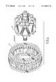
- FIG. 1is an exploded view showing a rotor and a stator of an electrical machine, in this case a claw pole alternator.
- FIG. 2is an electrical schematic showing the power windings and rectifier of an electrical machine such as the alternator of FIG. 1 .
- FIG. 3is a winding diagram for an auxiliary stator winding 40 according to one embodiment of the present invention.
- FIG. 4illustrates an electrical switch included for switchably opening and closing auxiliary stator winding 40 of FIG. 3 .
- An electrical machineincludes a rotor 20 and a stator 22 .
- rotor 20as the rotor from a Lundell or “claw pole” alternator.
- rotor 20has 12 magnetic poles.
- the alternatoris a three-phase machine, with stator 22 having a three-phase winding comprising phase windings 24 , 26 and 28 . Alternating current electrical power is generated in windings 24 , 26 and 28 when rotor 20 rotates.
- Bridge rectifier 30rectifies the alternating current power generated in windings 24 , 26 and 28 , providing the rectified power to output terminals 32 and 34 of the electrical machine.
- Neutral connection 36 of windings 24 , 26 and 28is also connected to rectifier 30 , in order to provide enhanced power output at high speed and high output current.
- a third harmonic fluxinduces a third harmonic voltage in windings 24 , 26 and 28 . This voltage is of sufficient magnitude to cause the diodes coupled to neutral point 36 to conduct, thus providing enhanced electrical output.
- Stator 22further includes an auxiliary electrical winding 40 , wound in the slots of stator 22 as shown.
- auxiliary winding 40is a 36 -pole winding (that is, it consecutively occupies each of the 36 slots in stator 22 ). Ends 42 and 44 of auxiliary winding 40 are preferably short-circuited.
- the 36 -pole third harmonic field generated by operation of the electrical machineinduces a voltage in auxiliary winding 40 . Because ends 42 and 44 of auxiliary winding 40 are short-circuited, the induced voltage causes a current to flow in auxiliary winding 40 . This current generates a field which opposes and partially cancels the third harmonic flux, reducing the noise associated with third harmonic flux.
- auxiliary winding 40One disadvantage of the use of auxiliary winding 40 is that the added output due to the neutral connection 36 of stator windings 24 , 26 and 28 being connected to rectifier 30 is substantially lost, due to the reduction of the third harmonic flux by auxiliary winding 40 .
- a switching devicesuch as transistor 50 can be provided to control the short-circuiting of auxiliary winding 40 .
- transistor 50can be closed. This will short-circuit auxiliary winding 40 to provide the noise-reduction benefits described above.
- transistor 50can be opened, resuming the benefit of having neutral connection 36 coupled to rectifier 30 .
- Suitable control circuitry 52such as a microprocessor-based controller having access to engine RPM data, can be used to control transistor 50 . Selection of transistor 50 can be facilitated by winding auxiliary winding 40 with multiple turns. Thus, less current will be required to provide its noise-reducing effect, and a lower-current-capacity transistor 50 can be selected.
- Auxiliary winding 40can be manufactured in various ways. First, it can be simply wound of wire in a conventional manner. It may also manufactured by providing electrically-conductive slot liners made of stamped metal such as copper. The slot liners can be inserted into the slots of stator 22 to line the bottom and/or sides of the slots. The slot liners are then electrically coupled together to create a one-turn auxiliary winding according to the winding diagram of FIG. 3 . Stator phase windings 24 , 26 and 28 are then wound into the slots of stator 22 in the conventional manner. Also, stator phase windings 24 , 26 and 28 may be wound first, with conductive wedges then placed on top of the phase windings. The wedges can be electrically interconnected to create an auxiliary winding according to FIG. 3 .
Landscapes
- Engineering & Computer Science (AREA)
- Power Engineering (AREA)
- Synchronous Machinery (AREA)
Abstract
Description
Claims (10)
Priority Applications (1)
| Application Number | Priority Date | Filing Date | Title |
|---|---|---|---|
| US09/221,483US6208057B1 (en) | 1998-12-28 | 1998-12-28 | Electrical machine with reduced audible noise |
Applications Claiming Priority (1)
| Application Number | Priority Date | Filing Date | Title |
|---|---|---|---|
| US09/221,483US6208057B1 (en) | 1998-12-28 | 1998-12-28 | Electrical machine with reduced audible noise |
Publications (1)
| Publication Number | Publication Date |
|---|---|
| US6208057B1true US6208057B1 (en) | 2001-03-27 |
Family
ID=22828004
Family Applications (1)
| Application Number | Title | Priority Date | Filing Date |
|---|---|---|---|
| US09/221,483Expired - Fee RelatedUS6208057B1 (en) | 1998-12-28 | 1998-12-28 | Electrical machine with reduced audible noise |
Country Status (1)
| Country | Link |
|---|---|
| US (1) | US6208057B1 (en) |
Cited By (8)
| Publication number | Priority date | Publication date | Assignee | Title |
|---|---|---|---|---|
| US6366000B1 (en)* | 2000-01-25 | 2002-04-02 | Mitsubishi Denki Kabushiki Kaisha | Alternator |
| US6469408B2 (en)* | 2000-07-31 | 2002-10-22 | Mitsubishi Denki Kabushiki Kaisha | Alternator |
| US20030095542A1 (en)* | 1997-07-25 | 2003-05-22 | Chang Gordon K. | Apparatus and method for integrated voice gateway |
| US20040114768A1 (en)* | 2002-12-11 | 2004-06-17 | Huageng Luo | System and method for noise cancellation |
| EP1544983A1 (en)* | 2003-12-19 | 2005-06-22 | Fanuc Ltd | Electric motor |
| US20100306102A1 (en)* | 1995-11-13 | 2010-12-02 | Lakshmi Arunachalam | Web Service Network Portal |
| US20140208579A1 (en)* | 2013-01-30 | 2014-07-31 | Victory Industrial Corporation | Manufacturing Method of a Stator of an Alternator |
| US20140210287A1 (en)* | 2013-01-30 | 2014-07-31 | Victory Industrial Corporation | Annular-Shaped Stator Structure and Method of Manufacture |
Citations (10)
| Publication number | Priority date | Publication date | Assignee | Title |
|---|---|---|---|---|
| US4110642A (en) | 1976-03-03 | 1978-08-29 | Robert Bosch Gmbh | Noise reduction arrangement in a claw-type dynamo electric machine, particularly multi-phase automotive-type a-c generator |
| US4201930A (en) | 1977-07-15 | 1980-05-06 | Nippon Soken, Inc. | AC Generator having a clawtooth rotor with irregular trapizoidal teeth |
| JPS55122466A (en) | 1979-03-16 | 1980-09-20 | Hitachi Ltd | Commutator machine |
| US4263526A (en) | 1978-04-10 | 1981-04-21 | Nippon Soken, Inc. | AC Generator with low noise claw tooth rotor |
| JPS6223348A (en)* | 1985-07-22 | 1987-01-31 | Sawafuji Electric Co Ltd | Brushless generator |
| US5122705A (en) | 1990-04-24 | 1992-06-16 | Nippondenso Co., Ltd. | Alternating current generator having a plurality of independent three-phase windings |
| US5172020A (en) | 1990-12-18 | 1992-12-15 | Kabushiki Kaisha Toshiba | Magnetic core for AC electrical equipments |
| US5256926A (en) | 1989-08-01 | 1993-10-26 | Robert Bosch Gmbh | Alternating-current generator with stator center lamination and method for producing the center lamination |
| US5691590A (en) | 1992-10-23 | 1997-11-25 | Nippondenso Co., Ltd. | Alternator with magnetic noise reduction mechanism |
| US5708316A (en) | 1992-10-23 | 1998-01-13 | Nippondenso Co., Ltd. | Altenator for a vehicle |
- 1998
- 1998-12-28USUS09/221,483patent/US6208057B1/ennot_activeExpired - Fee Related
Patent Citations (10)
| Publication number | Priority date | Publication date | Assignee | Title |
|---|---|---|---|---|
| US4110642A (en) | 1976-03-03 | 1978-08-29 | Robert Bosch Gmbh | Noise reduction arrangement in a claw-type dynamo electric machine, particularly multi-phase automotive-type a-c generator |
| US4201930A (en) | 1977-07-15 | 1980-05-06 | Nippon Soken, Inc. | AC Generator having a clawtooth rotor with irregular trapizoidal teeth |
| US4263526A (en) | 1978-04-10 | 1981-04-21 | Nippon Soken, Inc. | AC Generator with low noise claw tooth rotor |
| JPS55122466A (en) | 1979-03-16 | 1980-09-20 | Hitachi Ltd | Commutator machine |
| JPS6223348A (en)* | 1985-07-22 | 1987-01-31 | Sawafuji Electric Co Ltd | Brushless generator |
| US5256926A (en) | 1989-08-01 | 1993-10-26 | Robert Bosch Gmbh | Alternating-current generator with stator center lamination and method for producing the center lamination |
| US5122705A (en) | 1990-04-24 | 1992-06-16 | Nippondenso Co., Ltd. | Alternating current generator having a plurality of independent three-phase windings |
| US5172020A (en) | 1990-12-18 | 1992-12-15 | Kabushiki Kaisha Toshiba | Magnetic core for AC electrical equipments |
| US5691590A (en) | 1992-10-23 | 1997-11-25 | Nippondenso Co., Ltd. | Alternator with magnetic noise reduction mechanism |
| US5708316A (en) | 1992-10-23 | 1998-01-13 | Nippondenso Co., Ltd. | Altenator for a vehicle |
Cited By (13)
| Publication number | Priority date | Publication date | Assignee | Title |
|---|---|---|---|---|
| US20100306102A1 (en)* | 1995-11-13 | 2010-12-02 | Lakshmi Arunachalam | Web Service Network Portal |
| US20030095542A1 (en)* | 1997-07-25 | 2003-05-22 | Chang Gordon K. | Apparatus and method for integrated voice gateway |
| US6366000B1 (en)* | 2000-01-25 | 2002-04-02 | Mitsubishi Denki Kabushiki Kaisha | Alternator |
| US6469408B2 (en)* | 2000-07-31 | 2002-10-22 | Mitsubishi Denki Kabushiki Kaisha | Alternator |
| US7706547B2 (en) | 2002-12-11 | 2010-04-27 | General Electric Company | System and method for noise cancellation |
| US20040114768A1 (en)* | 2002-12-11 | 2004-06-17 | Huageng Luo | System and method for noise cancellation |
| US20050135024A1 (en)* | 2003-12-19 | 2005-06-23 | Fanuc Ltd | Electric motor |
| EP1544983A1 (en)* | 2003-12-19 | 2005-06-22 | Fanuc Ltd | Electric motor |
| US20140208579A1 (en)* | 2013-01-30 | 2014-07-31 | Victory Industrial Corporation | Manufacturing Method of a Stator of an Alternator |
| US20140210287A1 (en)* | 2013-01-30 | 2014-07-31 | Victory Industrial Corporation | Annular-Shaped Stator Structure and Method of Manufacture |
| TWI501509B (en)* | 2013-01-30 | 2015-09-21 | Victory Ind Corp | Alternator stator manufacturing method |
| TWI502855B (en)* | 2013-01-30 | 2015-10-01 | Victory Ind Corp | Alternator stator |
| TWI502856B (en)* | 2013-01-30 | 2015-10-01 | Victory Ind Corp | Alternator stator |
Similar Documents
| Publication | Publication Date | Title |
|---|---|---|
| Soong et al. | Field-weakening performance of interior permanent-magnet motors | |
| US7391180B2 (en) | Pulse width modulation control circuit for a multimode electrical machine, and a multimode electrical machine equipped with such a control circuit | |
| US20140239876A1 (en) | Electric drive with reconfigurable winding | |
| US20110057597A1 (en) | Electrical machine | |
| EP1764899B1 (en) | Starter generator for vehicle | |
| US5444355A (en) | Charging generator for a vehicle | |
| Chau et al. | Design and analysis of a stator-doubly-fed doubly-salient permanent-magnet machine for automotive engines | |
| US6208057B1 (en) | Electrical machine with reduced audible noise | |
| US20050006978A1 (en) | Twin coil claw pole rotor with stator phase shifting for electrical machine | |
| US5796233A (en) | Multiple-stator induction synchronous motor | |
| JP2003199306A (en) | Dynamo-electric machine | |
| Dajaku et al. | Opportunities of advanced multi-phase concentrated windings | |
| Fang et al. | Design and analysis of a novel flux-switching permanent magnet integrated-starter-generator | |
| US6707184B2 (en) | Permanent magnet type AC generator having short-circuiting control circuit | |
| JP2003536360A (en) | Methods for improving the efficiency of electric machines | |
| JP2003134766A (en) | Brushless electric rotating machine | |
| Fahimi | On the suitability of switched reluctance drives for starter/generator application | |
| US5386184A (en) | System for use with an electronically commutated electrical machine | |
| JP2003083209A (en) | Starter generator | |
| JP2003284378A (en) | Ac generator-motor apparatus for vehicle | |
| JPH11215729A (en) | Storage battery charger device | |
| JP2003102153A (en) | Alternating current generator-motor for vehicle | |
| JP3812782B2 (en) | Three-phase AC generator for vehicles | |
| Krefta et al. | Evaluation of propulsion drive system technologies for hybrid vehicles | |
| SU1458937A1 (en) | Single-phase induction motor |
Legal Events
| Date | Code | Title | Description |
|---|---|---|---|
| AS | Assignment | Owner name:FORD MOTOR COMPANY, MICHIGAN Free format text:ASSIGNMENT OF ASSIGNORS INTEREST;ASSIGNORS:SCHULTZ, ROY DAVID;SWALES, SHAWN;REEL/FRAME:009686/0869 Effective date:19981222 | |
| AS | Assignment | Owner name:VISTEON GLOBAL TECHNOLOGIES, INC., MICHIGAN Free format text:ASSIGNMENT OF ASSIGNORS INTEREST;ASSIGNOR:FORD MOTOR COMPANY;REEL/FRAME:010968/0220 Effective date:20000615 | |
| FPAY | Fee payment | Year of fee payment:4 | |
| AS | Assignment | Owner name:JPMORGAN CHASE BANK, N.A., AS ADMINISTRATIVE AGENT Free format text:SECURITY AGREEMENT;ASSIGNOR:VISTEON GLOBAL TECHNOLOGIES, INC.;REEL/FRAME:020497/0733 Effective date:20060613 | |
| FPAY | Fee payment | Year of fee payment:8 | |
| AS | Assignment | Owner name:JPMORGAN CHASE BANK, TEXAS Free format text:SECURITY INTEREST;ASSIGNOR:VISTEON GLOBAL TECHNOLOGIES, INC.;REEL/FRAME:022368/0001 Effective date:20060814 Owner name:JPMORGAN CHASE BANK,TEXAS Free format text:SECURITY INTEREST;ASSIGNOR:VISTEON GLOBAL TECHNOLOGIES, INC.;REEL/FRAME:022368/0001 Effective date:20060814 | |
| AS | Assignment | Owner name:WILMINGTON TRUST FSB, AS ADMINISTRATIVE AGENT, MIN Free format text:ASSIGNMENT OF SECURITY INTEREST IN PATENTS;ASSIGNOR:JPMORGAN CHASE BANK, N.A., AS ADMINISTRATIVE AGENT;REEL/FRAME:022575/0186 Effective date:20090415 Owner name:WILMINGTON TRUST FSB, AS ADMINISTRATIVE AGENT,MINN Free format text:ASSIGNMENT OF SECURITY INTEREST IN PATENTS;ASSIGNOR:JPMORGAN CHASE BANK, N.A., AS ADMINISTRATIVE AGENT;REEL/FRAME:022575/0186 Effective date:20090415 | |
| AS | Assignment | Owner name:THE BANK OF NEW YORK MELLON, AS ADMINISTRATIVE AGE Free format text:ASSIGNMENT OF PATENT SECURITY INTEREST;ASSIGNOR:JPMORGAN CHASE BANK, N.A., A NATIONAL BANKING ASSOCIATION;REEL/FRAME:022974/0057 Effective date:20090715 | |
| AS | Assignment | Owner name:VISTEON GLOBAL TECHNOLOGIES, INC., MICHIGAN Free format text:RELEASE BY SECURED PARTY AGAINST SECURITY INTEREST IN PATENTS RECORDED AT REEL 022974 FRAME 0057;ASSIGNOR:THE BANK OF NEW YORK MELLON;REEL/FRAME:025095/0711 Effective date:20101001 | |
| AS | Assignment | Owner name:VISTEON GLOBAL TECHNOLOGIES, INC., MICHIGAN Free format text:RELEASE BY SECURED PARTY AGAINST SECURITY INTEREST IN PATENTS RECORDED AT REEL 022575 FRAME 0186;ASSIGNOR:WILMINGTON TRUST FSB, AS ADMINISTRATIVE AGENT;REEL/FRAME:025105/0201 Effective date:20101001 | |
| AS | Assignment | Owner name:MORGAN STANLEY SENIOR FUNDING, INC., AS AGENT, NEW Free format text:SECURITY AGREEMENT (REVOLVER);ASSIGNORS:VISTEON CORPORATION;VC AVIATION SERVICES, LLC;VISTEON ELECTRONICS CORPORATION;AND OTHERS;REEL/FRAME:025238/0298 Effective date:20101001 Owner name:MORGAN STANLEY SENIOR FUNDING, INC., AS AGENT, NEW Free format text:SECURITY AGREEMENT;ASSIGNORS:VISTEON CORPORATION;VC AVIATION SERVICES, LLC;VISTEON ELECTRONICS CORPORATION;AND OTHERS;REEL/FRAME:025241/0317 Effective date:20101007 | |
| AS | Assignment | Owner name:VC AVIATION SERVICES, LLC, MICHIGAN Free format text:RELEASE BY SECURED PARTY AGAINST SECURITY INTEREST IN PATENTS ON REEL 025241 FRAME 0317;ASSIGNOR:MORGAN STANLEY SENIOR FUNDING, INC.;REEL/FRAME:026178/0412 Effective date:20110406 Owner name:VISTEON INTERNATIONAL HOLDINGS, INC., MICHIGAN Free format text:RELEASE BY SECURED PARTY AGAINST SECURITY INTEREST IN PATENTS ON REEL 025241 FRAME 0317;ASSIGNOR:MORGAN STANLEY SENIOR FUNDING, INC.;REEL/FRAME:026178/0412 Effective date:20110406 Owner name:VISTEON EUROPEAN HOLDING, INC., MICHIGAN Free format text:RELEASE BY SECURED PARTY AGAINST SECURITY INTEREST IN PATENTS ON REEL 025241 FRAME 0317;ASSIGNOR:MORGAN STANLEY SENIOR FUNDING, INC.;REEL/FRAME:026178/0412 Effective date:20110406 Owner name:VISTEON SYSTEMS, LLC, MICHIGAN Free format text:RELEASE BY SECURED PARTY AGAINST SECURITY INTEREST IN PATENTS ON REEL 025241 FRAME 0317;ASSIGNOR:MORGAN STANLEY SENIOR FUNDING, INC.;REEL/FRAME:026178/0412 Effective date:20110406 Owner name:VISTEON INTERNATIONAL BUSINESS DEVELOPMENT, INC., Free format text:RELEASE BY SECURED PARTY AGAINST SECURITY INTEREST IN PATENTS ON REEL 025241 FRAME 0317;ASSIGNOR:MORGAN STANLEY SENIOR FUNDING, INC.;REEL/FRAME:026178/0412 Effective date:20110406 Owner name:VISTEON GLOBAL TREASURY, INC., MICHIGAN Free format text:RELEASE BY SECURED PARTY AGAINST SECURITY INTEREST IN PATENTS ON REEL 025241 FRAME 0317;ASSIGNOR:MORGAN STANLEY SENIOR FUNDING, INC.;REEL/FRAME:026178/0412 Effective date:20110406 Owner name:VISTEON ELECTRONICS CORPORATION, MICHIGAN Free format text:RELEASE BY SECURED PARTY AGAINST SECURITY INTEREST IN PATENTS ON REEL 025241 FRAME 0317;ASSIGNOR:MORGAN STANLEY SENIOR FUNDING, INC.;REEL/FRAME:026178/0412 Effective date:20110406 Owner name:VISTEON CORPORATION, MICHIGAN Free format text:RELEASE BY SECURED PARTY AGAINST SECURITY INTEREST IN PATENTS ON REEL 025241 FRAME 0317;ASSIGNOR:MORGAN STANLEY SENIOR FUNDING, INC.;REEL/FRAME:026178/0412 Effective date:20110406 Owner name:VISTEON GLOBAL TECHNOLOGIES, INC., MICHIGAN Free format text:RELEASE BY SECURED PARTY AGAINST SECURITY INTEREST IN PATENTS ON REEL 025241 FRAME 0317;ASSIGNOR:MORGAN STANLEY SENIOR FUNDING, INC.;REEL/FRAME:026178/0412 Effective date:20110406 | |
| REMI | Maintenance fee reminder mailed | ||
| LAPS | Lapse for failure to pay maintenance fees | ||
| STCH | Information on status: patent discontinuation | Free format text:PATENT EXPIRED DUE TO NONPAYMENT OF MAINTENANCE FEES UNDER 37 CFR 1.362 | |
| FP | Lapsed due to failure to pay maintenance fee | Effective date:20130327 | |
| AS | Assignment | Owner name:VISTEON GLOBAL TECHNOLOGIES, INC., MICHIGAN Free format text:RELEASE OF SECURITY INTEREST IN INTELLECTUAL PROPERTY;ASSIGNOR:MORGAN STANLEY SENIOR FUNDING, INC.;REEL/FRAME:033107/0717 Effective date:20140409 Owner name:VISTEON EUROPEAN HOLDINGS, INC., MICHIGAN Free format text:RELEASE OF SECURITY INTEREST IN INTELLECTUAL PROPERTY;ASSIGNOR:MORGAN STANLEY SENIOR FUNDING, INC.;REEL/FRAME:033107/0717 Effective date:20140409 Owner name:VISTEON ELECTRONICS CORPORATION, MICHIGAN Free format text:RELEASE OF SECURITY INTEREST IN INTELLECTUAL PROPERTY;ASSIGNOR:MORGAN STANLEY SENIOR FUNDING, INC.;REEL/FRAME:033107/0717 Effective date:20140409 Owner name:VISTEON CORPORATION, MICHIGAN Free format text:RELEASE OF SECURITY INTEREST IN INTELLECTUAL PROPERTY;ASSIGNOR:MORGAN STANLEY SENIOR FUNDING, INC.;REEL/FRAME:033107/0717 Effective date:20140409 Owner name:VISTEON INTERNATIONAL BUSINESS DEVELOPMENT, INC., Free format text:RELEASE OF SECURITY INTEREST IN INTELLECTUAL PROPERTY;ASSIGNOR:MORGAN STANLEY SENIOR FUNDING, INC.;REEL/FRAME:033107/0717 Effective date:20140409 Owner name:VC AVIATION SERVICES, LLC, MICHIGAN Free format text:RELEASE OF SECURITY INTEREST IN INTELLECTUAL PROPERTY;ASSIGNOR:MORGAN STANLEY SENIOR FUNDING, INC.;REEL/FRAME:033107/0717 Effective date:20140409 Owner name:VISTEON SYSTEMS, LLC, MICHIGAN Free format text:RELEASE OF SECURITY INTEREST IN INTELLECTUAL PROPERTY;ASSIGNOR:MORGAN STANLEY SENIOR FUNDING, INC.;REEL/FRAME:033107/0717 Effective date:20140409 Owner name:VISTEON INTERNATIONAL HOLDINGS, INC., MICHIGAN Free format text:RELEASE OF SECURITY INTEREST IN INTELLECTUAL PROPERTY;ASSIGNOR:MORGAN STANLEY SENIOR FUNDING, INC.;REEL/FRAME:033107/0717 Effective date:20140409 Owner name:VISTEON GLOBAL TREASURY, INC., MICHIGAN Free format text:RELEASE OF SECURITY INTEREST IN INTELLECTUAL PROPERTY;ASSIGNOR:MORGAN STANLEY SENIOR FUNDING, INC.;REEL/FRAME:033107/0717 Effective date:20140409 |