US6206922B1 - Methods and instruments for interbody fusion - Google Patents
Methods and instruments for interbody fusionDownload PDFInfo
- Publication number
- US6206922B1 US6206922B1US09/014,901US1490198AUS6206922B1US 6206922 B1US6206922 B1US 6206922B1US 1490198 AUS1490198 AUS 1490198AUS 6206922 B1US6206922 B1US 6206922B1
- Authority
- US
- United States
- Prior art keywords
- disc space
- devices
- bore
- recess
- plate
- Prior art date
- Legal status (The legal status is an assumption and is not a legal conclusion. Google has not performed a legal analysis and makes no representation as to the accuracy of the status listed.)
- Expired - Lifetime
Links
Images


Classifications
- A—HUMAN NECESSITIES
- A61—MEDICAL OR VETERINARY SCIENCE; HYGIENE
- A61B—DIAGNOSIS; SURGERY; IDENTIFICATION
- A61B1/00—Instruments for performing medical examinations of the interior of cavities or tubes of the body by visual or photographical inspection, e.g. endoscopes; Illuminating arrangements therefor
- A61B1/313—Instruments for performing medical examinations of the interior of cavities or tubes of the body by visual or photographical inspection, e.g. endoscopes; Illuminating arrangements therefor for introducing through surgical openings, e.g. laparoscopes
- A61B1/3132—Instruments for performing medical examinations of the interior of cavities or tubes of the body by visual or photographical inspection, e.g. endoscopes; Illuminating arrangements therefor for introducing through surgical openings, e.g. laparoscopes for laparoscopy
- A—HUMAN NECESSITIES
- A61—MEDICAL OR VETERINARY SCIENCE; HYGIENE
- A61B—DIAGNOSIS; SURGERY; IDENTIFICATION
- A61B1/00—Instruments for performing medical examinations of the interior of cavities or tubes of the body by visual or photographical inspection, e.g. endoscopes; Illuminating arrangements therefor
- A61B1/313—Instruments for performing medical examinations of the interior of cavities or tubes of the body by visual or photographical inspection, e.g. endoscopes; Illuminating arrangements therefor for introducing through surgical openings, e.g. laparoscopes
- A61B1/3135—Instruments for performing medical examinations of the interior of cavities or tubes of the body by visual or photographical inspection, e.g. endoscopes; Illuminating arrangements therefor for introducing through surgical openings, e.g. laparoscopes for examination of the epidural or the spinal space
- A—HUMAN NECESSITIES
- A61—MEDICAL OR VETERINARY SCIENCE; HYGIENE
- A61B—DIAGNOSIS; SURGERY; IDENTIFICATION
- A61B17/00—Surgical instruments, devices or methods
- A61B17/02—Surgical instruments, devices or methods for holding wounds open, e.g. retractors; Tractors
- A61B17/025—Joint distractors
- A—HUMAN NECESSITIES
- A61—MEDICAL OR VETERINARY SCIENCE; HYGIENE
- A61B—DIAGNOSIS; SURGERY; IDENTIFICATION
- A61B17/00—Surgical instruments, devices or methods
- A61B17/16—Instruments for performing osteoclasis; Drills or chisels for bones; Trepans
- A61B17/1662—Instruments for performing osteoclasis; Drills or chisels for bones; Trepans for particular parts of the body
- A61B17/1671—Instruments for performing osteoclasis; Drills or chisels for bones; Trepans for particular parts of the body for the spine
- A—HUMAN NECESSITIES
- A61—MEDICAL OR VETERINARY SCIENCE; HYGIENE
- A61B—DIAGNOSIS; SURGERY; IDENTIFICATION
- A61B17/00—Surgical instruments, devices or methods
- A61B17/16—Instruments for performing osteoclasis; Drills or chisels for bones; Trepans
- A61B17/17—Guides or aligning means for drills, mills, pins or wires
- A61B17/1739—Guides or aligning means for drills, mills, pins or wires specially adapted for particular parts of the body
- A61B17/1757—Guides or aligning means for drills, mills, pins or wires specially adapted for particular parts of the body for the spine
- A—HUMAN NECESSITIES
- A61—MEDICAL OR VETERINARY SCIENCE; HYGIENE
- A61B—DIAGNOSIS; SURGERY; IDENTIFICATION
- A61B17/00—Surgical instruments, devices or methods
- A61B17/28—Surgical forceps
- A61B17/2812—Surgical forceps with a single pivotal connection
- A61B17/282—Jaws
- A—HUMAN NECESSITIES
- A61—MEDICAL OR VETERINARY SCIENCE; HYGIENE
- A61F—FILTERS IMPLANTABLE INTO BLOOD VESSELS; PROSTHESES; DEVICES PROVIDING PATENCY TO, OR PREVENTING COLLAPSING OF, TUBULAR STRUCTURES OF THE BODY, e.g. STENTS; ORTHOPAEDIC, NURSING OR CONTRACEPTIVE DEVICES; FOMENTATION; TREATMENT OR PROTECTION OF EYES OR EARS; BANDAGES, DRESSINGS OR ABSORBENT PADS; FIRST-AID KITS
- A61F2/00—Filters implantable into blood vessels; Prostheses, i.e. artificial substitutes or replacements for parts of the body; Appliances for connecting them with the body; Devices providing patency to, or preventing collapsing of, tubular structures of the body, e.g. stents
- A61F2/02—Prostheses implantable into the body
- A61F2/30—Joints
- A61F2/44—Joints for the spine, e.g. vertebrae, spinal discs
- A61F2/4455—Joints for the spine, e.g. vertebrae, spinal discs for the fusion of spinal bodies, e.g. intervertebral fusion of adjacent spinal bodies, e.g. fusion cages
- A61F2/446—Joints for the spine, e.g. vertebrae, spinal discs for the fusion of spinal bodies, e.g. intervertebral fusion of adjacent spinal bodies, e.g. fusion cages having a circular or elliptical cross-section substantially parallel to the axis of the spine, e.g. cylinders or frustocones
- A—HUMAN NECESSITIES
- A61—MEDICAL OR VETERINARY SCIENCE; HYGIENE
- A61F—FILTERS IMPLANTABLE INTO BLOOD VESSELS; PROSTHESES; DEVICES PROVIDING PATENCY TO, OR PREVENTING COLLAPSING OF, TUBULAR STRUCTURES OF THE BODY, e.g. STENTS; ORTHOPAEDIC, NURSING OR CONTRACEPTIVE DEVICES; FOMENTATION; TREATMENT OR PROTECTION OF EYES OR EARS; BANDAGES, DRESSINGS OR ABSORBENT PADS; FIRST-AID KITS
- A61F2/00—Filters implantable into blood vessels; Prostheses, i.e. artificial substitutes or replacements for parts of the body; Appliances for connecting them with the body; Devices providing patency to, or preventing collapsing of, tubular structures of the body, e.g. stents
- A61F2/02—Prostheses implantable into the body
- A61F2/30—Joints
- A61F2/46—Special tools for implanting artificial joints
- A61F2/4601—Special tools for implanting artificial joints for introducing bone substitute, for implanting bone graft implants or for compacting them in the bone cavity
- A—HUMAN NECESSITIES
- A61—MEDICAL OR VETERINARY SCIENCE; HYGIENE
- A61F—FILTERS IMPLANTABLE INTO BLOOD VESSELS; PROSTHESES; DEVICES PROVIDING PATENCY TO, OR PREVENTING COLLAPSING OF, TUBULAR STRUCTURES OF THE BODY, e.g. STENTS; ORTHOPAEDIC, NURSING OR CONTRACEPTIVE DEVICES; FOMENTATION; TREATMENT OR PROTECTION OF EYES OR EARS; BANDAGES, DRESSINGS OR ABSORBENT PADS; FIRST-AID KITS
- A61F2/00—Filters implantable into blood vessels; Prostheses, i.e. artificial substitutes or replacements for parts of the body; Appliances for connecting them with the body; Devices providing patency to, or preventing collapsing of, tubular structures of the body, e.g. stents
- A61F2/02—Prostheses implantable into the body
- A61F2/30—Joints
- A61F2/46—Special tools for implanting artificial joints
- A61F2/4603—Special tools for implanting artificial joints for insertion or extraction of endoprosthetic joints or of accessories thereof
- A61F2/4611—Special tools for implanting artificial joints for insertion or extraction of endoprosthetic joints or of accessories thereof of spinal prostheses
- A—HUMAN NECESSITIES
- A61—MEDICAL OR VETERINARY SCIENCE; HYGIENE
- A61B—DIAGNOSIS; SURGERY; IDENTIFICATION
- A61B17/00—Surgical instruments, devices or methods
- A61B17/56—Surgical instruments or methods for treatment of bones or joints; Devices specially adapted therefor
- A61B17/58—Surgical instruments or methods for treatment of bones or joints; Devices specially adapted therefor for osteosynthesis, e.g. bone plates, screws or setting implements
- A61B17/68—Internal fixation devices, including fasteners and spinal fixators, even if a part thereof projects from the skin
- A61B17/70—Spinal positioners or stabilisers, e.g. stabilisers comprising fluid filler in an implant
- A61B17/7059—Cortical plates
- A—HUMAN NECESSITIES
- A61—MEDICAL OR VETERINARY SCIENCE; HYGIENE
- A61B—DIAGNOSIS; SURGERY; IDENTIFICATION
- A61B17/00—Surgical instruments, devices or methods
- A61B17/56—Surgical instruments or methods for treatment of bones or joints; Devices specially adapted therefor
- A61B17/58—Surgical instruments or methods for treatment of bones or joints; Devices specially adapted therefor for osteosynthesis, e.g. bone plates, screws or setting implements
- A61B17/68—Internal fixation devices, including fasteners and spinal fixators, even if a part thereof projects from the skin
- A61B17/84—Fasteners therefor or fasteners being internal fixation devices
- A61B17/86—Pins or screws or threaded wires; nuts therefor
- A—HUMAN NECESSITIES
- A61—MEDICAL OR VETERINARY SCIENCE; HYGIENE
- A61B—DIAGNOSIS; SURGERY; IDENTIFICATION
- A61B17/00—Surgical instruments, devices or methods
- A61B17/00234—Surgical instruments, devices or methods for minimally invasive surgery
- A61B2017/00238—Type of minimally invasive operation
- A61B2017/00261—Discectomy
- A—HUMAN NECESSITIES
- A61—MEDICAL OR VETERINARY SCIENCE; HYGIENE
- A61B—DIAGNOSIS; SURGERY; IDENTIFICATION
- A61B17/00—Surgical instruments, devices or methods
- A61B17/02—Surgical instruments, devices or methods for holding wounds open, e.g. retractors; Tractors
- A61B17/025—Joint distractors
- A61B2017/0256—Joint distractors for the spine
- A—HUMAN NECESSITIES
- A61—MEDICAL OR VETERINARY SCIENCE; HYGIENE
- A61B—DIAGNOSIS; SURGERY; IDENTIFICATION
- A61B17/00—Surgical instruments, devices or methods
- A61B17/34—Trocars; Puncturing needles
- A61B2017/348—Means for supporting the trocar against the body or retaining the trocar inside the body
- A61B2017/3482—Means for supporting the trocar against the body or retaining the trocar inside the body inside
- A61B2017/3484—Anchoring means, e.g. spreading-out umbrella-like structure
- A61B2017/3488—Fixation to inner organ or inner body tissue
- A—HUMAN NECESSITIES
- A61—MEDICAL OR VETERINARY SCIENCE; HYGIENE
- A61B—DIAGNOSIS; SURGERY; IDENTIFICATION
- A61B90/00—Instruments, implements or accessories specially adapted for surgery or diagnosis and not covered by any of the groups A61B1/00 - A61B50/00, e.g. for luxation treatment or for protecting wound edges
- A61B90/39—Markers, e.g. radio-opaque or breast lesions markers
- A61B2090/3904—Markers, e.g. radio-opaque or breast lesions markers specially adapted for marking specified tissue
- A—HUMAN NECESSITIES
- A61—MEDICAL OR VETERINARY SCIENCE; HYGIENE
- A61B—DIAGNOSIS; SURGERY; IDENTIFICATION
- A61B90/00—Instruments, implements or accessories specially adapted for surgery or diagnosis and not covered by any of the groups A61B1/00 - A61B50/00, e.g. for luxation treatment or for protecting wound edges
- A61B90/39—Markers, e.g. radio-opaque or breast lesions markers
- A61B2090/3937—Visible markers
- A—HUMAN NECESSITIES
- A61—MEDICAL OR VETERINARY SCIENCE; HYGIENE
- A61F—FILTERS IMPLANTABLE INTO BLOOD VESSELS; PROSTHESES; DEVICES PROVIDING PATENCY TO, OR PREVENTING COLLAPSING OF, TUBULAR STRUCTURES OF THE BODY, e.g. STENTS; ORTHOPAEDIC, NURSING OR CONTRACEPTIVE DEVICES; FOMENTATION; TREATMENT OR PROTECTION OF EYES OR EARS; BANDAGES, DRESSINGS OR ABSORBENT PADS; FIRST-AID KITS
- A61F2/00—Filters implantable into blood vessels; Prostheses, i.e. artificial substitutes or replacements for parts of the body; Appliances for connecting them with the body; Devices providing patency to, or preventing collapsing of, tubular structures of the body, e.g. stents
- A61F2/02—Prostheses implantable into the body
- A61F2/30—Joints
- A61F2/44—Joints for the spine, e.g. vertebrae, spinal discs
- A61F2/442—Intervertebral or spinal discs, e.g. resilient
- A—HUMAN NECESSITIES
- A61—MEDICAL OR VETERINARY SCIENCE; HYGIENE
- A61F—FILTERS IMPLANTABLE INTO BLOOD VESSELS; PROSTHESES; DEVICES PROVIDING PATENCY TO, OR PREVENTING COLLAPSING OF, TUBULAR STRUCTURES OF THE BODY, e.g. STENTS; ORTHOPAEDIC, NURSING OR CONTRACEPTIVE DEVICES; FOMENTATION; TREATMENT OR PROTECTION OF EYES OR EARS; BANDAGES, DRESSINGS OR ABSORBENT PADS; FIRST-AID KITS
- A61F2/00—Filters implantable into blood vessels; Prostheses, i.e. artificial substitutes or replacements for parts of the body; Appliances for connecting them with the body; Devices providing patency to, or preventing collapsing of, tubular structures of the body, e.g. stents
- A61F2/02—Prostheses implantable into the body
- A61F2/28—Bones
- A61F2002/2835—Bone graft implants for filling a bony defect or an endoprosthesis cavity, e.g. by synthetic material or biological material
- A61F2002/2839—Bone plugs or bone graft dowels
- A—HUMAN NECESSITIES
- A61—MEDICAL OR VETERINARY SCIENCE; HYGIENE
- A61F—FILTERS IMPLANTABLE INTO BLOOD VESSELS; PROSTHESES; DEVICES PROVIDING PATENCY TO, OR PREVENTING COLLAPSING OF, TUBULAR STRUCTURES OF THE BODY, e.g. STENTS; ORTHOPAEDIC, NURSING OR CONTRACEPTIVE DEVICES; FOMENTATION; TREATMENT OR PROTECTION OF EYES OR EARS; BANDAGES, DRESSINGS OR ABSORBENT PADS; FIRST-AID KITS
- A61F2/00—Filters implantable into blood vessels; Prostheses, i.e. artificial substitutes or replacements for parts of the body; Appliances for connecting them with the body; Devices providing patency to, or preventing collapsing of, tubular structures of the body, e.g. stents
- A61F2/02—Prostheses implantable into the body
- A61F2/30—Joints
- A61F2002/30001—Additional features of subject-matter classified in A61F2/28, A61F2/30 and subgroups thereof
- A61F2002/30108—Shapes
- A61F2002/3011—Cross-sections or two-dimensional shapes
- A61F2002/30112—Rounded shapes, e.g. with rounded corners
- A61F2002/30113—Rounded shapes, e.g. with rounded corners circular
- A61F2002/30121—Rounded shapes, e.g. with rounded corners circular with lobes
- A61F2002/30123—Rounded shapes, e.g. with rounded corners circular with lobes with two diametrically opposed lobes
- A—HUMAN NECESSITIES
- A61—MEDICAL OR VETERINARY SCIENCE; HYGIENE
- A61F—FILTERS IMPLANTABLE INTO BLOOD VESSELS; PROSTHESES; DEVICES PROVIDING PATENCY TO, OR PREVENTING COLLAPSING OF, TUBULAR STRUCTURES OF THE BODY, e.g. STENTS; ORTHOPAEDIC, NURSING OR CONTRACEPTIVE DEVICES; FOMENTATION; TREATMENT OR PROTECTION OF EYES OR EARS; BANDAGES, DRESSINGS OR ABSORBENT PADS; FIRST-AID KITS
- A61F2/00—Filters implantable into blood vessels; Prostheses, i.e. artificial substitutes or replacements for parts of the body; Appliances for connecting them with the body; Devices providing patency to, or preventing collapsing of, tubular structures of the body, e.g. stents
- A61F2/02—Prostheses implantable into the body
- A61F2/30—Joints
- A61F2002/30001—Additional features of subject-matter classified in A61F2/28, A61F2/30 and subgroups thereof
- A61F2002/30108—Shapes
- A61F2002/3011—Cross-sections or two-dimensional shapes
- A61F2002/30138—Convex polygonal shapes
- A61F2002/30153—Convex polygonal shapes rectangular
- A—HUMAN NECESSITIES
- A61—MEDICAL OR VETERINARY SCIENCE; HYGIENE
- A61F—FILTERS IMPLANTABLE INTO BLOOD VESSELS; PROSTHESES; DEVICES PROVIDING PATENCY TO, OR PREVENTING COLLAPSING OF, TUBULAR STRUCTURES OF THE BODY, e.g. STENTS; ORTHOPAEDIC, NURSING OR CONTRACEPTIVE DEVICES; FOMENTATION; TREATMENT OR PROTECTION OF EYES OR EARS; BANDAGES, DRESSINGS OR ABSORBENT PADS; FIRST-AID KITS
- A61F2/00—Filters implantable into blood vessels; Prostheses, i.e. artificial substitutes or replacements for parts of the body; Appliances for connecting them with the body; Devices providing patency to, or preventing collapsing of, tubular structures of the body, e.g. stents
- A61F2/02—Prostheses implantable into the body
- A61F2/30—Joints
- A61F2002/30001—Additional features of subject-matter classified in A61F2/28, A61F2/30 and subgroups thereof
- A61F2002/30108—Shapes
- A61F2002/3011—Cross-sections or two-dimensional shapes
- A61F2002/30159—Concave polygonal shapes
- A61F2002/30179—X-shaped
- A—HUMAN NECESSITIES
- A61—MEDICAL OR VETERINARY SCIENCE; HYGIENE
- A61F—FILTERS IMPLANTABLE INTO BLOOD VESSELS; PROSTHESES; DEVICES PROVIDING PATENCY TO, OR PREVENTING COLLAPSING OF, TUBULAR STRUCTURES OF THE BODY, e.g. STENTS; ORTHOPAEDIC, NURSING OR CONTRACEPTIVE DEVICES; FOMENTATION; TREATMENT OR PROTECTION OF EYES OR EARS; BANDAGES, DRESSINGS OR ABSORBENT PADS; FIRST-AID KITS
- A61F2/00—Filters implantable into blood vessels; Prostheses, i.e. artificial substitutes or replacements for parts of the body; Appliances for connecting them with the body; Devices providing patency to, or preventing collapsing of, tubular structures of the body, e.g. stents
- A61F2/02—Prostheses implantable into the body
- A61F2/30—Joints
- A61F2002/30001—Additional features of subject-matter classified in A61F2/28, A61F2/30 and subgroups thereof
- A61F2002/30108—Shapes
- A61F2002/30199—Three-dimensional shapes
- A61F2002/30205—Three-dimensional shapes conical
- A61F2002/3021—Three-dimensional shapes conical frustoconical
- A—HUMAN NECESSITIES
- A61—MEDICAL OR VETERINARY SCIENCE; HYGIENE
- A61F—FILTERS IMPLANTABLE INTO BLOOD VESSELS; PROSTHESES; DEVICES PROVIDING PATENCY TO, OR PREVENTING COLLAPSING OF, TUBULAR STRUCTURES OF THE BODY, e.g. STENTS; ORTHOPAEDIC, NURSING OR CONTRACEPTIVE DEVICES; FOMENTATION; TREATMENT OR PROTECTION OF EYES OR EARS; BANDAGES, DRESSINGS OR ABSORBENT PADS; FIRST-AID KITS
- A61F2/00—Filters implantable into blood vessels; Prostheses, i.e. artificial substitutes or replacements for parts of the body; Appliances for connecting them with the body; Devices providing patency to, or preventing collapsing of, tubular structures of the body, e.g. stents
- A61F2/02—Prostheses implantable into the body
- A61F2/30—Joints
- A61F2002/30001—Additional features of subject-matter classified in A61F2/28, A61F2/30 and subgroups thereof
- A61F2002/30108—Shapes
- A61F2002/30199—Three-dimensional shapes
- A61F2002/30205—Three-dimensional shapes conical
- A61F2002/30217—Three-dimensional shapes conical hollow cones, e.g. tubular-like cones
- A—HUMAN NECESSITIES
- A61—MEDICAL OR VETERINARY SCIENCE; HYGIENE
- A61F—FILTERS IMPLANTABLE INTO BLOOD VESSELS; PROSTHESES; DEVICES PROVIDING PATENCY TO, OR PREVENTING COLLAPSING OF, TUBULAR STRUCTURES OF THE BODY, e.g. STENTS; ORTHOPAEDIC, NURSING OR CONTRACEPTIVE DEVICES; FOMENTATION; TREATMENT OR PROTECTION OF EYES OR EARS; BANDAGES, DRESSINGS OR ABSORBENT PADS; FIRST-AID KITS
- A61F2/00—Filters implantable into blood vessels; Prostheses, i.e. artificial substitutes or replacements for parts of the body; Appliances for connecting them with the body; Devices providing patency to, or preventing collapsing of, tubular structures of the body, e.g. stents
- A61F2/02—Prostheses implantable into the body
- A61F2/30—Joints
- A61F2002/30001—Additional features of subject-matter classified in A61F2/28, A61F2/30 and subgroups thereof
- A61F2002/30316—The prosthesis having different structural features at different locations within the same prosthesis; Connections between prosthetic parts; Special structural features of bone or joint prostheses not otherwise provided for
- A61F2002/30329—Connections or couplings between prosthetic parts, e.g. between modular parts; Connecting elements
- A61F2002/30433—Connections or couplings between prosthetic parts, e.g. between modular parts; Connecting elements using additional screws, bolts, dowels, rivets or washers e.g. connecting screws
- A—HUMAN NECESSITIES
- A61—MEDICAL OR VETERINARY SCIENCE; HYGIENE
- A61F—FILTERS IMPLANTABLE INTO BLOOD VESSELS; PROSTHESES; DEVICES PROVIDING PATENCY TO, OR PREVENTING COLLAPSING OF, TUBULAR STRUCTURES OF THE BODY, e.g. STENTS; ORTHOPAEDIC, NURSING OR CONTRACEPTIVE DEVICES; FOMENTATION; TREATMENT OR PROTECTION OF EYES OR EARS; BANDAGES, DRESSINGS OR ABSORBENT PADS; FIRST-AID KITS
- A61F2/00—Filters implantable into blood vessels; Prostheses, i.e. artificial substitutes or replacements for parts of the body; Appliances for connecting them with the body; Devices providing patency to, or preventing collapsing of, tubular structures of the body, e.g. stents
- A61F2/02—Prostheses implantable into the body
- A61F2/30—Joints
- A61F2002/30001—Additional features of subject-matter classified in A61F2/28, A61F2/30 and subgroups thereof
- A61F2002/30316—The prosthesis having different structural features at different locations within the same prosthesis; Connections between prosthetic parts; Special structural features of bone or joint prostheses not otherwise provided for
- A61F2002/30329—Connections or couplings between prosthetic parts, e.g. between modular parts; Connecting elements
- A61F2002/30476—Connections or couplings between prosthetic parts, e.g. between modular parts; Connecting elements locked by an additional locking mechanism
- A61F2002/30507—Connections or couplings between prosthetic parts, e.g. between modular parts; Connecting elements locked by an additional locking mechanism using a threaded locking member, e.g. a locking screw or a set screw
- A—HUMAN NECESSITIES
- A61—MEDICAL OR VETERINARY SCIENCE; HYGIENE
- A61F—FILTERS IMPLANTABLE INTO BLOOD VESSELS; PROSTHESES; DEVICES PROVIDING PATENCY TO, OR PREVENTING COLLAPSING OF, TUBULAR STRUCTURES OF THE BODY, e.g. STENTS; ORTHOPAEDIC, NURSING OR CONTRACEPTIVE DEVICES; FOMENTATION; TREATMENT OR PROTECTION OF EYES OR EARS; BANDAGES, DRESSINGS OR ABSORBENT PADS; FIRST-AID KITS
- A61F2/00—Filters implantable into blood vessels; Prostheses, i.e. artificial substitutes or replacements for parts of the body; Appliances for connecting them with the body; Devices providing patency to, or preventing collapsing of, tubular structures of the body, e.g. stents
- A61F2/02—Prostheses implantable into the body
- A61F2/30—Joints
- A61F2002/30001—Additional features of subject-matter classified in A61F2/28, A61F2/30 and subgroups thereof
- A61F2002/30316—The prosthesis having different structural features at different locations within the same prosthesis; Connections between prosthetic parts; Special structural features of bone or joint prostheses not otherwise provided for
- A61F2002/30535—Special structural features of bone or joint prostheses not otherwise provided for
- A61F2002/30593—Special structural features of bone or joint prostheses not otherwise provided for hollow
- A—HUMAN NECESSITIES
- A61—MEDICAL OR VETERINARY SCIENCE; HYGIENE
- A61F—FILTERS IMPLANTABLE INTO BLOOD VESSELS; PROSTHESES; DEVICES PROVIDING PATENCY TO, OR PREVENTING COLLAPSING OF, TUBULAR STRUCTURES OF THE BODY, e.g. STENTS; ORTHOPAEDIC, NURSING OR CONTRACEPTIVE DEVICES; FOMENTATION; TREATMENT OR PROTECTION OF EYES OR EARS; BANDAGES, DRESSINGS OR ABSORBENT PADS; FIRST-AID KITS
- A61F2/00—Filters implantable into blood vessels; Prostheses, i.e. artificial substitutes or replacements for parts of the body; Appliances for connecting them with the body; Devices providing patency to, or preventing collapsing of, tubular structures of the body, e.g. stents
- A61F2/02—Prostheses implantable into the body
- A61F2/30—Joints
- A61F2002/30001—Additional features of subject-matter classified in A61F2/28, A61F2/30 and subgroups thereof
- A61F2002/30316—The prosthesis having different structural features at different locations within the same prosthesis; Connections between prosthetic parts; Special structural features of bone or joint prostheses not otherwise provided for
- A61F2002/30535—Special structural features of bone or joint prostheses not otherwise provided for
- A61F2002/30604—Special structural features of bone or joint prostheses not otherwise provided for modular
- A—HUMAN NECESSITIES
- A61—MEDICAL OR VETERINARY SCIENCE; HYGIENE
- A61F—FILTERS IMPLANTABLE INTO BLOOD VESSELS; PROSTHESES; DEVICES PROVIDING PATENCY TO, OR PREVENTING COLLAPSING OF, TUBULAR STRUCTURES OF THE BODY, e.g. STENTS; ORTHOPAEDIC, NURSING OR CONTRACEPTIVE DEVICES; FOMENTATION; TREATMENT OR PROTECTION OF EYES OR EARS; BANDAGES, DRESSINGS OR ABSORBENT PADS; FIRST-AID KITS
- A61F2/00—Filters implantable into blood vessels; Prostheses, i.e. artificial substitutes or replacements for parts of the body; Appliances for connecting them with the body; Devices providing patency to, or preventing collapsing of, tubular structures of the body, e.g. stents
- A61F2/02—Prostheses implantable into the body
- A61F2/30—Joints
- A61F2/30767—Special external or bone-contacting surface, e.g. coating for improving bone ingrowth
- A61F2/30771—Special external or bone-contacting surface, e.g. coating for improving bone ingrowth applied in original prostheses, e.g. holes or grooves
- A61F2002/30772—Apertures or holes, e.g. of circular cross section
- A61F2002/30774—Apertures or holes, e.g. of circular cross section internally-threaded
- A—HUMAN NECESSITIES
- A61—MEDICAL OR VETERINARY SCIENCE; HYGIENE
- A61F—FILTERS IMPLANTABLE INTO BLOOD VESSELS; PROSTHESES; DEVICES PROVIDING PATENCY TO, OR PREVENTING COLLAPSING OF, TUBULAR STRUCTURES OF THE BODY, e.g. STENTS; ORTHOPAEDIC, NURSING OR CONTRACEPTIVE DEVICES; FOMENTATION; TREATMENT OR PROTECTION OF EYES OR EARS; BANDAGES, DRESSINGS OR ABSORBENT PADS; FIRST-AID KITS
- A61F2/00—Filters implantable into blood vessels; Prostheses, i.e. artificial substitutes or replacements for parts of the body; Appliances for connecting them with the body; Devices providing patency to, or preventing collapsing of, tubular structures of the body, e.g. stents
- A61F2/02—Prostheses implantable into the body
- A61F2/30—Joints
- A61F2/30767—Special external or bone-contacting surface, e.g. coating for improving bone ingrowth
- A61F2/30771—Special external or bone-contacting surface, e.g. coating for improving bone ingrowth applied in original prostheses, e.g. holes or grooves
- A61F2002/30772—Apertures or holes, e.g. of circular cross section
- A61F2002/30777—Oblong apertures
- A—HUMAN NECESSITIES
- A61—MEDICAL OR VETERINARY SCIENCE; HYGIENE
- A61F—FILTERS IMPLANTABLE INTO BLOOD VESSELS; PROSTHESES; DEVICES PROVIDING PATENCY TO, OR PREVENTING COLLAPSING OF, TUBULAR STRUCTURES OF THE BODY, e.g. STENTS; ORTHOPAEDIC, NURSING OR CONTRACEPTIVE DEVICES; FOMENTATION; TREATMENT OR PROTECTION OF EYES OR EARS; BANDAGES, DRESSINGS OR ABSORBENT PADS; FIRST-AID KITS
- A61F2/00—Filters implantable into blood vessels; Prostheses, i.e. artificial substitutes or replacements for parts of the body; Appliances for connecting them with the body; Devices providing patency to, or preventing collapsing of, tubular structures of the body, e.g. stents
- A61F2/02—Prostheses implantable into the body
- A61F2/30—Joints
- A61F2/30767—Special external or bone-contacting surface, e.g. coating for improving bone ingrowth
- A61F2/30771—Special external or bone-contacting surface, e.g. coating for improving bone ingrowth applied in original prostheses, e.g. holes or grooves
- A61F2002/30772—Apertures or holes, e.g. of circular cross section
- A61F2002/30784—Plurality of holes
- A61F2002/30785—Plurality of holes parallel
- A—HUMAN NECESSITIES
- A61—MEDICAL OR VETERINARY SCIENCE; HYGIENE
- A61F—FILTERS IMPLANTABLE INTO BLOOD VESSELS; PROSTHESES; DEVICES PROVIDING PATENCY TO, OR PREVENTING COLLAPSING OF, TUBULAR STRUCTURES OF THE BODY, e.g. STENTS; ORTHOPAEDIC, NURSING OR CONTRACEPTIVE DEVICES; FOMENTATION; TREATMENT OR PROTECTION OF EYES OR EARS; BANDAGES, DRESSINGS OR ABSORBENT PADS; FIRST-AID KITS
- A61F2/00—Filters implantable into blood vessels; Prostheses, i.e. artificial substitutes or replacements for parts of the body; Appliances for connecting them with the body; Devices providing patency to, or preventing collapsing of, tubular structures of the body, e.g. stents
- A61F2/02—Prostheses implantable into the body
- A61F2/30—Joints
- A61F2/30767—Special external or bone-contacting surface, e.g. coating for improving bone ingrowth
- A61F2/30771—Special external or bone-contacting surface, e.g. coating for improving bone ingrowth applied in original prostheses, e.g. holes or grooves
- A61F2002/30772—Apertures or holes, e.g. of circular cross section
- A61F2002/30784—Plurality of holes
- A61F2002/30787—Plurality of holes inclined obliquely with respect to each other
- A—HUMAN NECESSITIES
- A61—MEDICAL OR VETERINARY SCIENCE; HYGIENE
- A61F—FILTERS IMPLANTABLE INTO BLOOD VESSELS; PROSTHESES; DEVICES PROVIDING PATENCY TO, OR PREVENTING COLLAPSING OF, TUBULAR STRUCTURES OF THE BODY, e.g. STENTS; ORTHOPAEDIC, NURSING OR CONTRACEPTIVE DEVICES; FOMENTATION; TREATMENT OR PROTECTION OF EYES OR EARS; BANDAGES, DRESSINGS OR ABSORBENT PADS; FIRST-AID KITS
- A61F2/00—Filters implantable into blood vessels; Prostheses, i.e. artificial substitutes or replacements for parts of the body; Appliances for connecting them with the body; Devices providing patency to, or preventing collapsing of, tubular structures of the body, e.g. stents
- A61F2/02—Prostheses implantable into the body
- A61F2/30—Joints
- A61F2/30767—Special external or bone-contacting surface, e.g. coating for improving bone ingrowth
- A61F2/30771—Special external or bone-contacting surface, e.g. coating for improving bone ingrowth applied in original prostheses, e.g. holes or grooves
- A61F2002/30772—Apertures or holes, e.g. of circular cross section
- A61F2002/30784—Plurality of holes
- A61F2002/30789—Plurality of holes perpendicular with respect to each other
- A—HUMAN NECESSITIES
- A61—MEDICAL OR VETERINARY SCIENCE; HYGIENE
- A61F—FILTERS IMPLANTABLE INTO BLOOD VESSELS; PROSTHESES; DEVICES PROVIDING PATENCY TO, OR PREVENTING COLLAPSING OF, TUBULAR STRUCTURES OF THE BODY, e.g. STENTS; ORTHOPAEDIC, NURSING OR CONTRACEPTIVE DEVICES; FOMENTATION; TREATMENT OR PROTECTION OF EYES OR EARS; BANDAGES, DRESSINGS OR ABSORBENT PADS; FIRST-AID KITS
- A61F2/00—Filters implantable into blood vessels; Prostheses, i.e. artificial substitutes or replacements for parts of the body; Appliances for connecting them with the body; Devices providing patency to, or preventing collapsing of, tubular structures of the body, e.g. stents
- A61F2/02—Prostheses implantable into the body
- A61F2/30—Joints
- A61F2/30767—Special external or bone-contacting surface, e.g. coating for improving bone ingrowth
- A61F2/30771—Special external or bone-contacting surface, e.g. coating for improving bone ingrowth applied in original prostheses, e.g. holes or grooves
- A61F2002/3082—Grooves
- A—HUMAN NECESSITIES
- A61—MEDICAL OR VETERINARY SCIENCE; HYGIENE
- A61F—FILTERS IMPLANTABLE INTO BLOOD VESSELS; PROSTHESES; DEVICES PROVIDING PATENCY TO, OR PREVENTING COLLAPSING OF, TUBULAR STRUCTURES OF THE BODY, e.g. STENTS; ORTHOPAEDIC, NURSING OR CONTRACEPTIVE DEVICES; FOMENTATION; TREATMENT OR PROTECTION OF EYES OR EARS; BANDAGES, DRESSINGS OR ABSORBENT PADS; FIRST-AID KITS
- A61F2/00—Filters implantable into blood vessels; Prostheses, i.e. artificial substitutes or replacements for parts of the body; Appliances for connecting them with the body; Devices providing patency to, or preventing collapsing of, tubular structures of the body, e.g. stents
- A61F2/02—Prostheses implantable into the body
- A61F2/30—Joints
- A61F2/30767—Special external or bone-contacting surface, e.g. coating for improving bone ingrowth
- A61F2/30771—Special external or bone-contacting surface, e.g. coating for improving bone ingrowth applied in original prostheses, e.g. holes or grooves
- A61F2002/3085—Special external or bone-contacting surface, e.g. coating for improving bone ingrowth applied in original prostheses, e.g. holes or grooves with a threaded, e.g. self-tapping, bone-engaging surface, e.g. external surface
- A61F2002/30858—Threads interrupted by grooves or sidewalls, e.g. flat sidewalls
- A—HUMAN NECESSITIES
- A61—MEDICAL OR VETERINARY SCIENCE; HYGIENE
- A61F—FILTERS IMPLANTABLE INTO BLOOD VESSELS; PROSTHESES; DEVICES PROVIDING PATENCY TO, OR PREVENTING COLLAPSING OF, TUBULAR STRUCTURES OF THE BODY, e.g. STENTS; ORTHOPAEDIC, NURSING OR CONTRACEPTIVE DEVICES; FOMENTATION; TREATMENT OR PROTECTION OF EYES OR EARS; BANDAGES, DRESSINGS OR ABSORBENT PADS; FIRST-AID KITS
- A61F2/00—Filters implantable into blood vessels; Prostheses, i.e. artificial substitutes or replacements for parts of the body; Appliances for connecting them with the body; Devices providing patency to, or preventing collapsing of, tubular structures of the body, e.g. stents
- A61F2/02—Prostheses implantable into the body
- A61F2/30—Joints
- A61F2/30767—Special external or bone-contacting surface, e.g. coating for improving bone ingrowth
- A61F2/30771—Special external or bone-contacting surface, e.g. coating for improving bone ingrowth applied in original prostheses, e.g. holes or grooves
- A61F2002/3085—Special external or bone-contacting surface, e.g. coating for improving bone ingrowth applied in original prostheses, e.g. holes or grooves with a threaded, e.g. self-tapping, bone-engaging surface, e.g. external surface
- A61F2002/30863—Special external or bone-contacting surface, e.g. coating for improving bone ingrowth applied in original prostheses, e.g. holes or grooves with a threaded, e.g. self-tapping, bone-engaging surface, e.g. external surface the entry end surface having flutes, relief grooves, starter notches or bevelled indentations
- A—HUMAN NECESSITIES
- A61—MEDICAL OR VETERINARY SCIENCE; HYGIENE
- A61F—FILTERS IMPLANTABLE INTO BLOOD VESSELS; PROSTHESES; DEVICES PROVIDING PATENCY TO, OR PREVENTING COLLAPSING OF, TUBULAR STRUCTURES OF THE BODY, e.g. STENTS; ORTHOPAEDIC, NURSING OR CONTRACEPTIVE DEVICES; FOMENTATION; TREATMENT OR PROTECTION OF EYES OR EARS; BANDAGES, DRESSINGS OR ABSORBENT PADS; FIRST-AID KITS
- A61F2/00—Filters implantable into blood vessels; Prostheses, i.e. artificial substitutes or replacements for parts of the body; Appliances for connecting them with the body; Devices providing patency to, or preventing collapsing of, tubular structures of the body, e.g. stents
- A61F2/02—Prostheses implantable into the body
- A61F2/30—Joints
- A61F2/30767—Special external or bone-contacting surface, e.g. coating for improving bone ingrowth
- A61F2/30771—Special external or bone-contacting surface, e.g. coating for improving bone ingrowth applied in original prostheses, e.g. holes or grooves
- A61F2002/3085—Special external or bone-contacting surface, e.g. coating for improving bone ingrowth applied in original prostheses, e.g. holes or grooves with a threaded, e.g. self-tapping, bone-engaging surface, e.g. external surface
- A61F2002/30871—Trapezoidal threads
- A—HUMAN NECESSITIES
- A61—MEDICAL OR VETERINARY SCIENCE; HYGIENE
- A61F—FILTERS IMPLANTABLE INTO BLOOD VESSELS; PROSTHESES; DEVICES PROVIDING PATENCY TO, OR PREVENTING COLLAPSING OF, TUBULAR STRUCTURES OF THE BODY, e.g. STENTS; ORTHOPAEDIC, NURSING OR CONTRACEPTIVE DEVICES; FOMENTATION; TREATMENT OR PROTECTION OF EYES OR EARS; BANDAGES, DRESSINGS OR ABSORBENT PADS; FIRST-AID KITS
- A61F2/00—Filters implantable into blood vessels; Prostheses, i.e. artificial substitutes or replacements for parts of the body; Appliances for connecting them with the body; Devices providing patency to, or preventing collapsing of, tubular structures of the body, e.g. stents
- A61F2/02—Prostheses implantable into the body
- A61F2/30—Joints
- A61F2/30767—Special external or bone-contacting surface, e.g. coating for improving bone ingrowth
- A61F2/30771—Special external or bone-contacting surface, e.g. coating for improving bone ingrowth applied in original prostheses, e.g. holes or grooves
- A61F2002/3085—Special external or bone-contacting surface, e.g. coating for improving bone ingrowth applied in original prostheses, e.g. holes or grooves with a threaded, e.g. self-tapping, bone-engaging surface, e.g. external surface
- A61F2002/30873—Threadings machined on non-cylindrical external surfaces
- A—HUMAN NECESSITIES
- A61—MEDICAL OR VETERINARY SCIENCE; HYGIENE
- A61F—FILTERS IMPLANTABLE INTO BLOOD VESSELS; PROSTHESES; DEVICES PROVIDING PATENCY TO, OR PREVENTING COLLAPSING OF, TUBULAR STRUCTURES OF THE BODY, e.g. STENTS; ORTHOPAEDIC, NURSING OR CONTRACEPTIVE DEVICES; FOMENTATION; TREATMENT OR PROTECTION OF EYES OR EARS; BANDAGES, DRESSINGS OR ABSORBENT PADS; FIRST-AID KITS
- A61F2/00—Filters implantable into blood vessels; Prostheses, i.e. artificial substitutes or replacements for parts of the body; Appliances for connecting them with the body; Devices providing patency to, or preventing collapsing of, tubular structures of the body, e.g. stents
- A61F2/02—Prostheses implantable into the body
- A61F2/30—Joints
- A61F2/44—Joints for the spine, e.g. vertebrae, spinal discs
- A61F2002/448—Joints for the spine, e.g. vertebrae, spinal discs comprising multiple adjacent spinal implants within the same intervertebral space or within the same vertebra, e.g. comprising two adjacent spinal implants
- A—HUMAN NECESSITIES
- A61—MEDICAL OR VETERINARY SCIENCE; HYGIENE
- A61F—FILTERS IMPLANTABLE INTO BLOOD VESSELS; PROSTHESES; DEVICES PROVIDING PATENCY TO, OR PREVENTING COLLAPSING OF, TUBULAR STRUCTURES OF THE BODY, e.g. STENTS; ORTHOPAEDIC, NURSING OR CONTRACEPTIVE DEVICES; FOMENTATION; TREATMENT OR PROTECTION OF EYES OR EARS; BANDAGES, DRESSINGS OR ABSORBENT PADS; FIRST-AID KITS
- A61F2/00—Filters implantable into blood vessels; Prostheses, i.e. artificial substitutes or replacements for parts of the body; Appliances for connecting them with the body; Devices providing patency to, or preventing collapsing of, tubular structures of the body, e.g. stents
- A61F2/02—Prostheses implantable into the body
- A61F2/30—Joints
- A61F2/46—Special tools for implanting artificial joints
- A61F2/4603—Special tools for implanting artificial joints for insertion or extraction of endoprosthetic joints or of accessories thereof
- A61F2002/4625—Special tools for implanting artificial joints for insertion or extraction of endoprosthetic joints or of accessories thereof with relative movement between parts of the instrument during use
- A61F2002/4627—Special tools for implanting artificial joints for insertion or extraction of endoprosthetic joints or of accessories thereof with relative movement between parts of the instrument during use with linear motion along or rotating motion about the instrument axis or the implantation direction, e.g. telescopic, along a guiding rod, screwing inside the instrument
- A—HUMAN NECESSITIES
- A61—MEDICAL OR VETERINARY SCIENCE; HYGIENE
- A61F—FILTERS IMPLANTABLE INTO BLOOD VESSELS; PROSTHESES; DEVICES PROVIDING PATENCY TO, OR PREVENTING COLLAPSING OF, TUBULAR STRUCTURES OF THE BODY, e.g. STENTS; ORTHOPAEDIC, NURSING OR CONTRACEPTIVE DEVICES; FOMENTATION; TREATMENT OR PROTECTION OF EYES OR EARS; BANDAGES, DRESSINGS OR ABSORBENT PADS; FIRST-AID KITS
- A61F2/00—Filters implantable into blood vessels; Prostheses, i.e. artificial substitutes or replacements for parts of the body; Appliances for connecting them with the body; Devices providing patency to, or preventing collapsing of, tubular structures of the body, e.g. stents
- A61F2/02—Prostheses implantable into the body
- A61F2/30—Joints
- A61F2/46—Special tools for implanting artificial joints
- A61F2002/4635—Special tools for implanting artificial joints using minimally invasive surgery
- A—HUMAN NECESSITIES
- A61—MEDICAL OR VETERINARY SCIENCE; HYGIENE
- A61F—FILTERS IMPLANTABLE INTO BLOOD VESSELS; PROSTHESES; DEVICES PROVIDING PATENCY TO, OR PREVENTING COLLAPSING OF, TUBULAR STRUCTURES OF THE BODY, e.g. STENTS; ORTHOPAEDIC, NURSING OR CONTRACEPTIVE DEVICES; FOMENTATION; TREATMENT OR PROTECTION OF EYES OR EARS; BANDAGES, DRESSINGS OR ABSORBENT PADS; FIRST-AID KITS
- A61F2220/00—Fixations or connections for prostheses classified in groups A61F2/00 - A61F2/26 or A61F2/82 or A61F9/00 or A61F11/00 or subgroups thereof
- A61F2220/0025—Connections or couplings between prosthetic parts, e.g. between modular parts; Connecting elements
- A61F2220/0041—Connections or couplings between prosthetic parts, e.g. between modular parts; Connecting elements using additional screws, bolts, dowels or rivets, e.g. connecting screws
- A—HUMAN NECESSITIES
- A61—MEDICAL OR VETERINARY SCIENCE; HYGIENE
- A61F—FILTERS IMPLANTABLE INTO BLOOD VESSELS; PROSTHESES; DEVICES PROVIDING PATENCY TO, OR PREVENTING COLLAPSING OF, TUBULAR STRUCTURES OF THE BODY, e.g. STENTS; ORTHOPAEDIC, NURSING OR CONTRACEPTIVE DEVICES; FOMENTATION; TREATMENT OR PROTECTION OF EYES OR EARS; BANDAGES, DRESSINGS OR ABSORBENT PADS; FIRST-AID KITS
- A61F2230/00—Geometry of prostheses classified in groups A61F2/00 - A61F2/26 or A61F2/82 or A61F9/00 or A61F11/00 or subgroups thereof
- A61F2230/0002—Two-dimensional shapes, e.g. cross-sections
- A61F2230/0004—Rounded shapes, e.g. with rounded corners
- A61F2230/0006—Rounded shapes, e.g. with rounded corners circular
- A—HUMAN NECESSITIES
- A61—MEDICAL OR VETERINARY SCIENCE; HYGIENE
- A61F—FILTERS IMPLANTABLE INTO BLOOD VESSELS; PROSTHESES; DEVICES PROVIDING PATENCY TO, OR PREVENTING COLLAPSING OF, TUBULAR STRUCTURES OF THE BODY, e.g. STENTS; ORTHOPAEDIC, NURSING OR CONTRACEPTIVE DEVICES; FOMENTATION; TREATMENT OR PROTECTION OF EYES OR EARS; BANDAGES, DRESSINGS OR ABSORBENT PADS; FIRST-AID KITS
- A61F2230/00—Geometry of prostheses classified in groups A61F2/00 - A61F2/26 or A61F2/82 or A61F9/00 or A61F11/00 or subgroups thereof
- A61F2230/0002—Two-dimensional shapes, e.g. cross-sections
- A61F2230/0017—Angular shapes
- A61F2230/0019—Angular shapes rectangular
- A—HUMAN NECESSITIES
- A61—MEDICAL OR VETERINARY SCIENCE; HYGIENE
- A61F—FILTERS IMPLANTABLE INTO BLOOD VESSELS; PROSTHESES; DEVICES PROVIDING PATENCY TO, OR PREVENTING COLLAPSING OF, TUBULAR STRUCTURES OF THE BODY, e.g. STENTS; ORTHOPAEDIC, NURSING OR CONTRACEPTIVE DEVICES; FOMENTATION; TREATMENT OR PROTECTION OF EYES OR EARS; BANDAGES, DRESSINGS OR ABSORBENT PADS; FIRST-AID KITS
- A61F2230/00—Geometry of prostheses classified in groups A61F2/00 - A61F2/26 or A61F2/82 or A61F9/00 or A61F11/00 or subgroups thereof
- A61F2230/0002—Two-dimensional shapes, e.g. cross-sections
- A61F2230/0028—Shapes in the form of latin or greek characters
- A61F2230/0058—X-shaped
- A—HUMAN NECESSITIES
- A61—MEDICAL OR VETERINARY SCIENCE; HYGIENE
- A61F—FILTERS IMPLANTABLE INTO BLOOD VESSELS; PROSTHESES; DEVICES PROVIDING PATENCY TO, OR PREVENTING COLLAPSING OF, TUBULAR STRUCTURES OF THE BODY, e.g. STENTS; ORTHOPAEDIC, NURSING OR CONTRACEPTIVE DEVICES; FOMENTATION; TREATMENT OR PROTECTION OF EYES OR EARS; BANDAGES, DRESSINGS OR ABSORBENT PADS; FIRST-AID KITS
- A61F2230/00—Geometry of prostheses classified in groups A61F2/00 - A61F2/26 or A61F2/82 or A61F9/00 or A61F11/00 or subgroups thereof
- A61F2230/0063—Three-dimensional shapes
- A61F2230/0067—Three-dimensional shapes conical
Definitions
- the present inventionrelates to methods and instruments for performing an interbody fusion of a disc space between two adjacent vertebrae. Specifically, the invention concerns laparoscopic techniques and instruments to prepare a fusion site and to insert fusion devices and implants.
- the number of spinal surgeries to correct the causes of low back painhas steadily increased over the last several years. Most often, low back pain originates from damage or defects in the spinal disc between adjacent vertebrae.
- the disccan be herniated or can be suffering from a variety of degenerative conditions, so that in either case the anatomical function of the spinal disc is disrupted.
- the most prevalent surgical treatment for these types of conditionshas been to fuse the two vertebrae surrounding the affected disc. In most cases, the entire disc will be removed, except for the annulus, by way of a discectomy procedure. Since the damaged disc material has been removed, something must be positioned within the intradiscal space, otherwise the space may collapse resulting in damage to the nerves extending along the spinal column.
- the intradiscal spaceis often filled with bone or a bone substitute in order to prevent disc space collapse and to promote fusion of the two adjacent vertebrae.
- bone materialwas simply disposed between the adjacent vertebrae, typically at the posterior aspect of the vertebrae, and the spine column was stabilized by way of a plate or a rod spanning the affected vertebrae. Once fusion occurred the hardware used to maintain the stability of the segment became superfluous. Moreover, the: surgical procedures necessary to implant a rod or plate to stabilize the level during fusion were frequently lengthy and involved.
- Interbody fusion devicescan be generally divided into two basic categories, namely solid implants and implants that are designed to permit bone ingrowth.
- Solid implantsare represented by U.S. Pat. Nos. 4,878,915; 4,743,256; 4,349,921 and 4,714,469.
- the remaining patents discussed aboveinclude some aspect that permits bone to grow across the implant. It has been found that devices that promote natural bone ingrowth achieve a more rapid and stable arthrodesis.
- the device depicted in the Michelson patentis representative of this type of hollow implant which is typically filled with autologous bone prior to insertion into the intradiscal space.
- This implantincludes a plurality of circular apertures which communicate with the hollow interior of the implant, thereby providing a path for tissue growth between the vertebral end plates and the bone or bone substitute within the implant.
- the end platesare preferably reduced to bleeding bone to facilitate this tissue ingrowth.
- the metal structure provided by the Michelson implanthelps maintain the patency and stability of the motion segment to be fused.
- the implantitself serves as a sort of anchor for the solid bony mass.
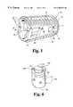
- FIG. 1Another interbody fusion device that is designed to permit bone ingrowth is shown in FIG. 1 .
- This deviceis described and claimed in co-pending parent application Ser. No. 08/411,017, filed on Mar. 27, 1995, which disclosure is incorporated herein by reference.
- this inventioncontemplates a hollow threaded interbody fusion device 10 configured to restore the normal angular relation between adjacent vertebrae.
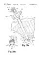
- the device 10 as shown in FIG. 1includes an elongated body 11 , tapered along substantially its entire length, defining a hollow interior 15 and having a largest outer diameter at the anterior end 12 of the device to receive the bone growth material.
- the body 11includes an outer surface 16 with opposite tapered cylindrical portions and a pair of opposite flat tapered side surfaces 22 between the cylindrical portions.
- the fusion devicegives the appearance of a cylindrical body in which the sides of the body have been truncated along a chord of the body's diameter.
- the cylindrical portionsinclude threads 18 for controlled insertion and engagement into the end plates of the adjacent vertebrae.
- a started thread 19is provided at the posterior end 13 of the device 10 to facilitate engagement within a prepared bore.
- the outer surface of this fusion deviceis tapered along its length at an angle corresponding, in one embodiment, to the normal lordotic angle of the lower lumbar vertebrae.
- the outer surfaceis also provided with a number of vascularization openings 24 , 25 defined in the flat side surfaces, and a pair of opposite elongated bone ingrowth slots 27 defined in the cylindrical portions.
- a long distractorhaving penetrating portions that urge the vertebral bodies apart to facilitate the introduction of the necessary instruments.
- the long distractorcan act as a guide for drilling and reaming tools concentrically advanced over the outside of the distractor to prepare the site for the fusion device.
- a novel fusion devicethat integrates a pair of bone screws.
- the fusion devicecan be a hollow substantially cylindrical body, such as the device shown in FIG. 1 .
- the deviceincludes a pair of screw bores formed in an end face of the body. The bores are arranged so that bone screws extending through the bores will be driven into the endplates of the adjacent vertebrae.
- the heads of the bone screwsare recessed within the body and held in place by a common locking screw. The screws help prevent retrograde expulsion or rotation of the fusion device, or a spacer, from the disc space.
- the present inventionalso contemplates another approach to preventing rotation and/or dislodgment of fusion devices placed bilaterally in the disc space.
- a transverse connector plateis engaged by locking screws to the end walls of the bilateral fusion devices.
- the end wallsdefine central recesses and transverse grooves to receive the connector plate.
- the connector platecan include screw bores to receive bone screws driven into the vertebrae at a location in between the fusion devices.
- a methodfor preparing a subject disc space for implantation of a fusion device or implant between adjacent vertebrae.
- a laparoscopeis provided that includes an outer sleeve with opposite extensions at one end of the outer sleeve and a laparoscopic port engaged at the outer end of the outer sleeve, the laparoscopic port having a number of seals, with the opposite extensions configured to maintain distraction of the adjacent vertebrae.
- the preferred techniquecomprises the steps of making an incision in the skin of the patient aligned with the subject disc space, retracting tissue beneath the incision to expose the disc annulus; and piercing the disc annulus to create an opening.
- the outer sleeve of the laparoscopeis advanced through the incision, leaving the port outside the skin of the patient while inserting the opposite extensions into the disc space with the outer sleeve contacting the disc annulus.
- the laparoscope, and particularly, the outer sleevecreates a protected working channel between the disc space and the laparoscopic port outside the patient.
- a reameris operated through the number of seals and the outer sleeve of the laparoscope to create a prepared bore in the disc material and the adjacent vertebrae for implantation of a device into the bore.
- the techniquecomprises the steps of percutaneously exposing the annulus of the disc in the subject disc space through an incision in the skin of the patient and piercing the disc annulus to create an opening.
- a distractorcan then be inserted through the incision and through the opening into the disc space to distract the vertebrae adjacent the subject disc space.
- the laparoscope outer sleeveis then introduced through the incision and over the distractor, leaving the port outside the skin of the patient while inserting the opposite extensions through the opening into the disc space to create the protected working channel between the port and the distractor tip.
- the distractoris removed and a reamer is advanced through the number of seals of the laparoscope and through the outer sleeve into the disc space to ream the disc space and adjacent vertebrae to create a prepared bore for the fusion implant.
- the fusion implantcan be advanced through the number of seals and through the outer sleeve into the prepared bore. With the fusion implant in position, the laparoscope can be withdrawn from the patient.
- a switching sleeveis placed within the outer sleeve of the laparoscope with an end of the switching sleeve projecting beyond the opposite fingers of the outer sleeve, the end of the switching sleeve being tapered to minimize trauma to tissue adjacent the subject disc space as the outer sleeve adjacent into the patient with the switching sleeve projecting beyond the opposite extensions of the outer sleeve.
- the laparoscopic methodis used for bilateral placement of two fusion devices into a subject disc space.
- this embodiment of the surgical techniqueincludes unseating the outer sleeve of the laparoscope from the first opening in the disc annulus by withdrawing the laparoscope until the opposite extensions of the outer sleeve are outside the disc annulus. With the switching sleeve in position within the outer sleeve, the laparoscope is moved to the second opening in the disc space without removing the laparoscope from the patient.
- the steps for preparing the bore to receive a fusion implantcan be repeated. In one specific embodiment, these steps are conducted at the second opening with the distractor remaining within the first opening.
- the laparoscopecan then be returned to the first opening for insertion of another fusion implant.
- the fusion implant contained within the second prepared boremaintains distraction of the disc space.
- a distraction devicein one aspect of the invention.
- the distraction devicecan include an elongated stem sized for insertion along the A-P midline of the intervertebral disc space.
- opposite surfaces of the deviceinclude a number of ridges that operate as bone engaging surfaces to resist expulsion of the device.
- the stem of the distraction deviceincludes a bore to receive a spike projecting from a tubular body, such as the outer sleeve discussed above. With this feature, the distraction device acts not only as a midline distractor, but also as a centering guide to locate the tubular body through which subsequent surgical procedures can be performed.
- the distraction devicecan include a flange projecting from the stem.
- the flangehas a bone contacting that transmits to the vertebra a force applied to the distraction device (preferably by a manual tool). This flange can be used to reduce a high grade spondylolisthesis condition as the distraction device is driven into the disc space.
- One object of the present inventionis to provide surgical technique and instruments that permit the preparation of a disc space for insertion of a fusion implant under a sealed condition.
- a further object of the inventionis to implement laparoscopic techniques to implant fusion devices.
- one objectis to enhance the stability of the device in situ while reducing the risk of expulsion of the device. Yet another object is to provide means for readily reducing a spondylolisthesis condition from a laparoscopic approach.
- One benefit of the present inventionis that all of the steps necessary to prepare a disc space and to implant a fusion device can be conducted in a protected environment.
- the inventive techniques and instrumentsallow minimal intrusion into the patient, which minimized the risks normally associated with spinal surgery.
- FIG. 1is a side perspective view of a threaded fusion device having a tapered configuration to restore the normal angle of a spinal motion segment.
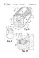
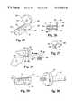
- FIG. 2is a top elevational view of an implant driver for use in engaging and driving a fusion device such as the device shown in FIG. 1 .
- FIG. 3is an enlarged perspective view of the end of the implant driver shown in FIG. 2 engaged to a fusion device such as shown in FIG. 1 .
- FIG. 4is an enlarged side cross-sectional view of the implant driver and fusion device shown in FIG. 3 .
- FIG. 5is an enlarged side cross-sectional view of an alternative embodiment of an implant driver for engaging and driving a fusion device such as the device shown in FIG. 1 .
- FIG. 6is a driving tool attachment according to one aspect of the present invention.
- FIG. 7is an enlarged side cross-sectional view similar to the view in FIG. 5 with the driving tool attachment of FIG. 6 engaged between the implant driver and the fusion device.
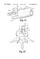
- FIG. 8is an end perspective view of a threaded fusion device according to a further embodiment of the invention.
- FIG. 9is a side perspective view of a driving tool attachment according to a further aspect of the present invention in which the driving tool attachment is configured to engage the fusion device depicted in FIG. 8 .
- FIG. 10is a side partial cross-sectional view of a fusion device according to the embodiment of FIG. 8 disposed between adjacent vertebrae and engaged in position by a pair of bone screws in accordance with one aspect of the present invention.
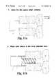
- FIGS. 11 ( a )-( d )are lateral representations of the spine showing four steps of a surgical method for implanting a fusion device such as the device in FIG. 1 according to an anterior approach in one aspect of the present invention.
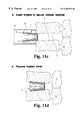
- FIGS. 12 ( a )-( d )are lateral representations of the spine showing four steps of a surgical method for implanting a fusion device such as the device in FIG. 1 according to a posterior approach in a further aspect of the present invention.
- FIG. 13is a frontal view of a patient with locations identified for surgical incisions according to a preferred embodiment of the present inventive laparoscopic surgical technique.
- FIG. 14is an A-P representation of a spinal segment at the laparoscopic surgical site depicting one step of the inventive surgical technique in which bilateral locations are marked on the disc annulus for insertion of a pair of fusion devices, such as the device shown in FIG. 1 .
- FIG. 15is an enlarged A-P view of the disc at the spinal segment showing the use of the template represented in FIG. 14 of the invention.
- FIG. 16is an A-P representation of the laparoscopic surgical site depicting a further step of the inventive surgical technique of creating a pilot hole at each of the bilateral locations marked in the step shown in FIG. 14 .
- FIG. 17is an A-P representation of the laparoscopic surgical site depicting a further step of the inventive surgical technique of using a trephine to create a bore at each of the bilateral locations marked in the step shown in FIG. 14 .
- FIG. 18is an A-P representation of the laparoscopic surgical site depicting a further step of the inventive surgical technique for inserting a distractor into the prepared site at each of the bilateral locations marked in the step shown in FIG. 11 .
- FIG. 19is a perspective representation of the laparoscope according to the present invention in which the outer sleeve of the laparoscope is engaged within the subject disc space.
- FIG. 20 ( a )is a perspective representation of the laparoscope of FIG. 19 with a switching sleeve according to one aspect of the invention disposed within the laparoscope.
- FIG. 20 ( b )is an enlarged A-P representation of the laparoscope and switching sleeve of FIG. 20 ( a ) showing the positioning of the distractor tip as depicted in FIG. 18 .
- FIG. 21is a perspective representation of the laparoscope of FIG. 19 with a reamer extending through the laparoscope to prepare the site for receiving a fusion device.
- FIG. 22is a perspective view of an implant driver of the type shown in FIG. 2 engaged to a fusion device and including a T-handle assembly engaged to the driver.
- FIG. 23is a perspective view of an implant holder according to one aspect of the present invention.
- FIG. 24is a perspective representation of the laparoscope used to implant a bone dowel within the prepared site and including a bone dowel impactor in accordance with one aspect of the present invention.
- FIG. 25is a top perspective view of a distraction plug in accordance with one embodiment of the present invention.
- FIG. 26is a side cross-sectional view of the distraction plug shown in FIG. 25 .
- FIG. 27is an end elevational view of the distraction plug shown in FIGS. 25 and 26.
- FIG. 28is a side view of the distraction plug shown in FIG. 25 as it is inserted between adjacent vertebrae using a plug driver in accordance with one aspect of the present invention.
- FIG. 29is a side perspective view of a distraction plug in accordance with a further embodiment of the present invention.
- FIG. 30is a side perspective view of a plug driver in accordance with a further embodiment of the invention configured for engaging a distractor plug as shown in FIG. 29 .
- FIG. 31is a rear perspective view of a percutaneous surgical sleeve in engagement with a distractor plug in accordance with the embodiment shown in FIG. 25 .
- FIG. 32is a superior A-P view of a vertebra of the spine with the distractor plug and percutaneous surgical sleeve shown in FIG. 31 disposed within the disc space, with an alternative position of the sleeve shown in phantom.
- FIG. 33is a side perspective view of a percutaneous surgical sleeve in accordance with a further embodiment of the invention with an outrigger spike engaged thereto for attachment to a distractor plug according to FIGS. 25 or 29 .
- FIG. 34is an end perspective view of a double barrel percutaneous surgical sleeve configured for engaging a distractor plug, such as the distractor plug shown in FIG. 29 .
- FIG. 35is a side perspective view of an assembly in accordance with a further embodiment of the present invention utilizing a pair of fusion devices connected by a connector plate.
- FIG. 36is a side perspective view of an alternative embodiment of the assembly with a pair of fusion devices interconnected by an alternative connector plate.
- one interbody fusion devicecan be implanted within the intradiscal space.
- This interbody fusion device 10can be implanted using the implant driver 50 shown in FIG. 2 .
- the implant driver 50is comprised of a shaft 51 and sleeve 52 concentrically disposed about the shaft.
- Tongs 54are formed at one end of the shaft for gripping the interbody fusion device 10 for implantation.
- the tongsinclude a tapered outer surface 55 and an opposite flat inner surface 56 adapted to engage the truncated side walls 22 of the interbody fusion device as shown in FIGS. 3, 4 .
- the tapered outer surface 55conforms to the root diameter of the interrupted threads 18 of the device 10 so that the tongs 54 essentially complete the full cylindrical shape of the body wall 16 .
- the adaptation of the tongs' tapered outer surface 55facilitates screw insertion of the interbody fusion device 10 since the outer surface 55 will ride within the tapped bore in the vertebral end plates.
- each of the tongs 54can be provided with interlocking fingers 58 and a driving projection 59 extending from the inner surface 56 , most clearly shown in FIG. 4 .
- the shaft 51defines a hinge slot 62 supporting each of the pair of tongs 54 .
- the hinge slot 62is configured so that the tongs will have a naturally biased position spread sufficiently apart to accept the fusion device 10 therebetween.
- the shaft 51defines a conical taper 63 between the hinged slot 62 and each of the tongs 54 . This conical taper mates with a conical chamfer 67 defined on the inner wall of the sleeve 52 .
- the conical chamfer 67rides against the conical taper 63 to close or compress the hinge slot 62 .
- the tongs 54are pushed toward each other and pressed into gripping engagement with the interbody fusion device situated between the tongs.
- the shaft 51 and sleeve 52are provided with a threaded interface 65 which permits the sleeve 52 to be threaded up and down the length of the shaft.
- the threaded interface 65includes external threads on the shaft 51 and internal threads on the sleeve 52 having the same pitch so that the sleeve can be readily moved up and down the implant driver 50 .
- the shaft 51is also provided with a pair of stops 69 which restrict the backward movement of the sleeve 52 to only the extent necessary to allow the tongs 54 to separate a sufficient distance to accept the interbody fusion device 10 .
- the implant driver 50is shown with reference to FIGS. 3, 4 .
- the outer surface 55 of the tongs 54reside generally flush with the root diameter of the interrupted threads 18 .
- the interlocking fingers 58can be arranged to fit within the vascularization opening 24 on each of the truncated side walls 22 .
- the driving projections 59engage the driving tool slots 29 at the anterior end 12 of the conical body 11 .
- the combination of the interlocking fingers 58 and driving projections 59firmly engage the interbody fusion device 10 so that the device can be screw threaded into a tapped or untapped opening in the vertebral bone.
- the tongs 54 in this embodimentare configured to engage the fusion device 10 and to impart a threading or rotational force to the device. It is understood that the tongs can adopt other configurations depending upon the structure of the fusion device to be implanted.
- the driver 90includes a shalt 91 , having a length sufficient to reach into the intradiscal space from outside the patient
- a headConnected to the end of shaft 91 is a head which defines a pair of opposite tongs 93 , each of which are configured for flush contact with the flat truncated side walls 22 of the fusion device 10 .
- the outer surface of the tongsis cylindrical to correspond to the cylindrical threaded portion of the device.
- the driver 90 of the embodiment in FIG. 5uses an expanding collet assembly to firmly grip the fusion device 10 for insertion into the body.
- the head 92defines a collet 94 having a central collet bore 95 formed therethrough.
- the collet 94terminates in an annular flange 96 that at least initially has a diameter slightly smaller than the inner diameter of the fusion device 10 at its end 12 .
- An expander shaft 97slidably extends through the collet bore and includes a flared tip 98 situated adjacent and extending just beyond the annular flange 96 .
- the flared tip 98 of the expander shaft 97starts at a diameter sized to slide within the collet bore 95 and gradually flares to a diameter larger than the bore.
- the implant driver 90further includes a puller shaft 99 slidably disposed within a bore 100 defined in the shaft 91 .
- the puller shaft 99has a locking chamber 101 at its end which engages a locking hub 102 formed at the end of the expander shaft 97 .
- the puller shaft 99projects beyond the end of the shaft 91 for access by the surgeon. When the puller shaft 99 is pulled, it pulls the expander shaft 97 away from the annular flange 96 of the collet 94 so that the flared tip 98 becomes progressively engaged within the collet bore 95 .
- the implant drivercan be used to insert the device 10 into the surgical site, after which the expander shaft can be advanced beyond the collet bore to release the flat tip and, consequently, the fusion device.
- the driving tool attachment 120includes a body 121 having a first end 122 and an opposite second end 123 .
- the body 121 of the driving tool attachment 120includes a cylindrical portion 125 and opposite flat side portions 126 .
- the opposite side portions 126are configured to be engaged by the tongs of the above driving tools 50 or 90 .
- the driving tool attachment 120includes a pair of opposing flanges 130 at end 123 .
- the flanges 130are configured to engage the opposite flat surface 122 on the fusion implant 10 , in a manner similar to that accomplished by the tongs of the implant driver 50 and 90 .
- the end 123also includes a boss 131 which is configured to be inserted into the opening at the end of the implant 10 (see FIG. 7 ).
- the driving tool attachment 120can be engaged with one of the driving tools 50 or 90 , with the tongs firmly grasping the flat surfaces 126 , as shown in FIG. 7 .
- the driving tool attachmentcan then be advanced into the disc space with the flanges 130 oriented across the space so that they can readily interface with the flat surfaces 22 of the fusion device 10 .
- the boss 131projects into the hollow opening 15 at the anterior end 12 of the fusion device and the flanges 130 engage the opposite flat surfaces 22 of the device.
- the driving toolcan then be rotated as if the fusion implant were directly engaged to the main driving tool.
- the attachmentreadily transmits the rotational driving force to the implant 10 to thread it deeper into the disc space or to retract it back within the disc space.
- One particular advantage provided by the driving tool attachment 120is that the relatively flexible tongs of the two driving tools 50 and 90 can be already engaged to the attachment 120 before insertion into the surgical site. This eliminates a great deal of fiddle factor and avoids the risk that the tongs would be unable to firmly grasp the implant 10 when it is already in position within the disc space.
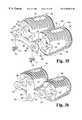
- an interbody fusion devicethat permits supplemental fastening to the adjacent vertebrae.
- an interbody fusion device 250includes a hollow body 251 having a first end 252 and a second end 253 .
- the hollow body 251defines a hollow interior 255 and includes an end wall 256 at the first end 252 .
- the interbody fusion device 250includes external threads 258 spanning a substantial portion of the length of the hollow body 251 , and a continuous thread 259 adjacent the second end 253 of the body.
- the interbody fusion device 250includes opposite flat sidewalls 262 that interrupt the external threads 258 , as well as opposing slots 263 offset from the flat sidewalls 262 which also interrupts a portion of the external threads 258 .
- the interbody fusion device 250is substantially similar to the device 10 shown in FIG. 1 .
- the devicecan be tapered so that it has a larger diameter at the first end 252 than at the second end 253 .
- side windows 264can be provided in the flat sidewalls 262 .
- the side walls 262essentially divide the body 251 into upper and lower threaded portions that are configured to be threadedly driven into adjacent vertebrae.
- the interbody fusion device 250includes a pair of driver openings 265 defined in the end wall 256 at the first end 252 . Intermediate between the driver openings 265 are a pair of offset screw bores 267 .
- the screw bores 267are formed so that their respective longitudinal axes intersect and project out from the top and bottom portions 260 , 261 .
- the axesare arranged to intersect the slots 263 in the top and bottom of the fusion device.
- the longitudinal axes of the two screw boresintersect outside the hollow body 251 and the end wall 256 , as seen in FIG. 10.
- a threaded bore 270is formed between the two screw bores 267 .
- the screw bores 267also define a recessed portion 268 , while the threaded bore defines a recessed portion 271 that intersects each of the recessed portions 268 of the screw bores 267 at an overlap 272 .
- a driving tool attachment 275is provided that permits insertion of the device within a properly prepared intervertebral space.
- the driving tool attachment 275is similar to the implant driver shown in FIG. 6 .
- the driving tool attachment 275includes a body 276 having opposite flat sidewalls 277 , so that the body is adapted to be engaged by the implant driver 90 in the manner depicted in FIG. 7 .
- the driving tool attachment 275includes a pair of spaced-apart driving bosses 278 projecting from a mating face 279 .
- the bosses 278are sized and shaped to fit within the driver openings 265 when the mating face 279 is in direct contact with the end wall 256 of the fusion device 250 .
- the driving tool attachment 275can be engaged to a fusion device, such as device 250 , to permit threading of the device into the intervertebral disc space, such as the space between lumbar vertebrae L 4 and L 5 , as shown in FIG. 10 .
- a pair of bone screws 280can be extended through respective screw bores 267 in the hollow body 251 .
- the screwsare passed through the bores 267 until the bone engaging threads of the screws 280 contact the vertebral bone.
- the head 281 of each of the bone screws 280seats within the respective recessed portions 268 of each of the screw bores 267 .
- the heads 281 of the bone screws 280are flush with or below the surface of the end wall 256 of the fusion device 250 .
- a locking screw 282can be threaded into the threaded bore 270 .
- the head 283 of the locking screwcontacts the heads 281 of both bone screws 280 . Further tightening of the locking screw 282 causes the head 283 to seat within the recessed portion 271 to trap the heads 281 of the bone screws 280 within their respective screw bores 267 . Thus, the set screw 282 prevents backout of the bone screws 280 when they are engaged within the adjacent vertebrae.
- the diverging bone screws 280provide greater stability to the fusion device 250 than can be achieved with prior threaded devices.
- the bone screwsenhance the resistance to retrograde expulsion of the device and prevents counter-rotation or unthreading.
- the bone screws 280can be of a wide range of sized provided that the screws are long enough to achieve an effective purchase in the adjacent vertebrae.
- an anterior approachis shown.
- a distractor 75is disposed between the vertebral end plates E to dilate the L 4 -L 5 or L 5 -S 1 disc space. (It is understood, of course, that this procedure can be applied at other vertebral levels).
- an outer sleeve 76is disposed about the disc space.
- the outer sleeve 76can be configured to positively engage the anterior aspect of the vertebral bodies to firmly, but temporarily, anchor the outer sleeve 76 in position. In essence, this outer sleeve 76 operates as a working channel for this approach.
- a drill 77 of know designis extended through the outer sleeve and used to drill out circular openings in the adjacent vertebral bodies. The openings can be tapped to facilitate screw insertion of the fusion device 10 , although this step is not necessary.
- the fusion device 10is engaged by the implant driver 50 and extended through the outer sleeve 76 until the starter thread 19 contacts the bone opening.
- the implant driver 50can then be used to screw thread the fusion device into the tapped or untapped opening formed in the vertebral end plate E.
- other suitable driving toolscould be used, such as a screw driver configured to engage the driving tool slots 29 at the anterior end 12 of the device 10 .
- the degree of insertion of the fusion device 10determines the amount of lordosis added or restored to the vertebral level.
- the implant driveris removed leaving the fusion device 10 in position. It can be seen that once implanted, the closed posterior end 13 is directed toward the posterior aspect of the vertebrae.
- the hollow interior 15is open at its anterior end 12 , but can be closed by a plastic or metal material, if necessary.
- a posterior approachis implemented.
- the first two steps of the posterior approachare similar to that of the prior anterior approach, except that the distractor 75 , outer sleeve 76 and drill 77 are introduced posteriorly at the instrumented motion segment.
- This approachmay require decortication and removal of vertebral bone to accept the outer sleeve 76 .
- the fusion device 10is inserted through the outer sleeve 76 into the dilated disc space. It is understood that the disc space is preferably dilated only to the extent necessary to receive the implant with the truncated side walls 22 directly facing the vertebral end plates E.
- a suitable driving tool 80can be provided to project the fusion device 10 through the outer sleeve 76 and into the intradiscal space.
- the driving tool 80includes a projection 81 which is configured to engage a slot opening formed in the end wall at the posterior end 13 of the fusion device 10 .
- An internal thread(not shown) can be used to fix the device 10 to the driver 80 .
- the driving tool 80is used to rotate the implant in the direction of the rotational arrow R in FIG. 12 ( c ).
- the deviceitself rotates so that the interrupted threads 18 start cutting into the vertebral bone at the end plates E.
- the implantoperates as a cam to separate the adjacent vertebrae in the direction of the spreading direction arrows S in FIG. 12 ( c ).
- This camming approachprovides a somewhat easier insertion procedure than for the anterior approach of FIGS. 11 ( a )-( d ) in that a single rotation is required to lock the implant into the vertebral bone.
- the formerly discussed screw insertion technique of the anterior approachrequires continuous threading of the device into position.
- the position of the fusion device 10 with respect to the adjacent vertebraecan be verified by radiograph or other suitable techniques for establishing the angular relationship between the vertebrae.
- the preferred depth of insertion of the implantcan be determined in advance and measured from outside the patient as the implant is positioned between the vertebrae. The depth of insertion of the fusion device can be ascertained using depth markings (not shown) on the implant drivers 50 , 90 or 80 .
- laparoscopic technologyis used to provide a sealed and protected channel for instruments and implants directed to the subject disc space.
- an anterior approach to the L 5 -S 1 motion segmentis illustrated. It is of course understood that these same techniques and instruments to be described below could be used at different vertebral levels or in a posterior approach under appropriate conditions.
- the present inventive techniqueincludes making a small incision 140 and preferably inserting an insufflator needle into the abdominal cavity. Fluid is introduced into the abdominal cavity through the insufflator needle to a pressure of preferably approximately 15 mm of mercury to assist in visualization of the surgical site.
- An initial port 141 for the laparoscopeis placed five to ten centimeters cephalad of the umbilicus in the midline ten millimeters in length.
- the abdomenis visually explored and the patient is placed in steep Trandelenburg.
- the abdominal wallis visualized endoscopically as two working ports 142 , 143 are placed just lateral to the epigastric vessels, opposite the level or levels to be fused. It is believed to be advantageous to stagger the ports slightly from direct opposition to each other.
- the preferred methodcontinues with insertion of retractors through the ports 142 , 143 .
- the retractorscan be used to sweep the small bowel superiorly out of the pelvis.
- the sigmoid colonis also pulled out of the pelvis and held laterally with the left fan retractor.
- the sacral promontory and drop-offcan be easily seen at this point.
- the posterior peritoneum overlying the L 5 -S 1 disc spaceis then incised longitudinally with endoshears for the desired exposure.
- opposing fan retractorsas blunt dissectors, the soft tissue underlying the parietal peritoneum can be swept laterally to bilaterally expose the anterior L 5 -S 2 disc annulus.
- the sacral artery and vein coursing the discare individually ligated with hemoclips and transected.
- a dissectorcan be used to remove residual soft tissue over the disc. Exposure is maintained with the left fan retractor in place holding the colon out of the way. It has been found that usually the right side does not require retraction, so a suction irrigation catheter can be used through this port.
- the posterior peritoneumis incised more proximally about 3 centimeters.
- the left fanis used to retract the colon laterally and with careful blunt dissection the aorta is exposed anteriorly at the bifurcation.
- the L 4 -L 5 discis usually right below this point.
- Left lateral dissectionis carried out over the left common iliac vein and artery, gently retracting these vessels to the right. In order to retract these vessels enough to the right for adequate disc exposure the ascending segmental vein branch must be identified and transected. Once this vessel is cut, the artery and vein can then be bluntly retracted to the right with a fan or loop retractor to expose a significant amount of the L 4 -L 5 disc for fusion.
- the abdominal entry operating trocar port site 145with the disc to be fused so that the operating trocar is parallel with the endplates of the disc in the sagittal plane.
- the entry pointis estimated and a small Steinmann pin can be placed either in the interspace or along the patient and checked with lateral C-arm and adjusted accordingly.
- a 1.5 to 2.5 centimeter incisioncan be made for placement of the operating trocar.
- a blunt introduceris placed in the abdomen and an 18 mm working trocar 147 (FIG. 14) can be placed over it under endoscopic visualization.
- the annular of the subject disc Dis marked for bilateral placement of a pair of fusion devices.
- a working trocar 147is situated within the working port 145 (see FIG. 13 ).
- the bilateral markscan be made with a template 150 , as shown in general in FIG. 14 and in more detail in FIG. 15 . Greater detail concerning this template and its method of use can be found in U.S. Pat. No. 5,645,549, issued on Jul. 8, 1997. The description of this template in this co-pending application is incorporated herein by reference.
- the template 150includes tubular body 151 and an elongated guide foot 152 that is pivotable connected to the end 153 of the tubular body.
- a guide wire or stylet 155extends through the tubular body to pivot the foot 152 to the side.
- the sharp tip 156 of the styletcan then be used to pierce the disc annulus D.
- the templatecan be secured to the center of the disc space by driving the stylet 156 into the disc tangential to the curvature of the annulus and parallel to the endplates.
- the templatecan then be slide down the guide wire or stylet until the foot 152 contacts the disc annulus.
- the footincludes an opening 157 through which an electrocautery device 160 can extend.
- the tip 161 of the electrocautery deviceis guided through the opening 157 in the foot 152 to contact the disc annulus D.
- the template 150can then be rotated in the direction of the arrow T so that the foot is situated laterally opposite the first mark MR.
- the electrocautery devicecan be used to make a second mark ML providing the bilateral positions for the two fusion devices.
- the surgeonhas a visual indication as to the proper location for placement of the fusion device.
- the surgeoncan then direct a T-handle probe 160 through the working port 147 to the either of the cauterization marks MR and ML (FIG. 16 ).
- the T-handle probe 160includes a sharp tip 161 that is used to break through the disc annulus. The T-handle allows the surgeon to rotate the probe 160 as necessary to facilitate penetration into the annulus.
- a T-handle trephine 165can be used to create pilot holes for subsequent instrumentation.
- the T-handle trephine 165can include a series of marking 166 at 5 mm increments to control the depth of insertion of the trephine into the disc space, as shown in FIG. 17 .
- the markings 166are compared to the working trocar 147 to gauge the depth of the cutting edge of the trephine, and therefore the depth of the prepared bore in the disc space and vertebral endplates.
- the T-handle of the trephineallows the surgeon to rotate the trephine 165 .
- the trephine 165is also preferably used to core into the disc space to form bilateral bores.
- a rongeurmay be used to clear disc material from each of the bilateral bores in the disc.
- a distractor 167is advanced through the working trocar 147 as shown in FIG. 18 .
- the distractorhas a distractor tip 169 that is selected according to the vertebral level being instrumented.
- distractors for a 16 mm size implantcan be either 12 mm or 14 mm in width to maintain the disc space at its proper anatomical height.
- the tip 169is removably attached to a distractor shaft 168 .
- progressively larger distractor tipsare sequentially inserted in alternating fashion into each of the bilateral holes in the disc space and annulus until the annulus is taut and the adjacent vertebrae are adequately distracted for restoration of a proper disc space height.
- the distractor tips 169once they are disposed in their bilateral positions, will acts as a centering point or alignment guide for use of the instruments throughout the remainder of the procedure. It is therefore important that the distractor tips 169 be properly located, which can be accurately confirmed with fluoroscopy.
- the laparoscope 170includes an outer sleeve 171 having a first end 172 and a second end 173 , as shown in FIG. 19 .
- the second end 173is engaged to a laparoscopic port 180 which can be of conventional design.
- the laparoscopic port 180can include a bore 184 (FIG.
- This bore 184 in the laparoscopic portallows introduction of instruments through the port and into the outer sleeve 171 .
- the boreis preferably closed by a number of seals 182 , which are configured to accept cylindrical tools and instruments therethrough while maintaining tight sealed engagement about the instrument.
- the laparoscopic port 180also preferably includes a trumpet valve 183 , which can be of conventional design. Specifically, the trumpet valve 183 maintains the laparoscopic port 180 in a normally closed position in which its internal bore is closed from communication with the outer sleeve 171 . However, once a instrument is introduced into the port 180 through the seals 182 , the trumpet valve 183 moves aside to allow passage of the instrument or tool into the sleeve 171 .
- the end 172 of the outer sleeve 171includes a pair of opposite distraction extensions or fingers 173 .
- These distraction fingers 173are sized according to the height of the particular disc space. Specifically, the fingers 173 are intended to maintain the spacing between the adjacent vertebrae during subsequent steps of the procedure after the distractor tip 169 has been removed.
- the width of the fingers 173can be varied depending upon the particular vertebral level being instrumented.
- the distraction fingers 173can be tapered to conform to a normal angle between adjacent vertebrae at the instrumented level.
- the position of the fingers 713is correlated with the position of the distractor tips within the bilateral bores in the disc space by aligning the fingers 173 with the trumpet valve 183 when the port 180 is engaged to the outer sleeve 171 .
- the trumpet valvesprovide a visual indication of the alignment of the fingers. In other words, when the trumpet valve 183 is lateral to the midline, the fingers 173 are properly oriented between the vertebral endplates.
- the outer sleeve 171can include opposite spikes 174 disposed between the distraction fingers 173 . These spikes are preferably configured to penetrate at least partially into the adjacent vertebral bodies, to help maintain the position of the outer sleeve 171 at the surgical site. In some instances, the outer sleeve 171 does not include the teeth 174 . For example, where the procedure is to implant a tapered fusion device, the teeth 174 are preferably eliminated and where the device is a uniform cylinder, the teeth can be retained.
- the laparoscope 170can be directly inserted over the distractor shaft extension (not shown).
- the distraction fingers 173 and the spikes 172can cause trauma to the skin during entry and to the soft tissue surrounding the surgical site during introduction of the laparoscope 170 .
- a further feature of the preferred embodimentincludes a switching sleeve 190 , as shown in FIGS. 20 ( a ), ( b ).
- the switching sleeve 190has a length sufficient to span the entire length of the laparoscope 170 from the port seals 182 to the end 172 of the outer sleeve 171 .
- the switching sleeve 190has a tapered tip 191 configured to extend beyond the end 172 of the outer sleeve 171 , and more particularly beyond the ends of the fingers 173 .
- the switching sleeve 190also includes a flared tip 192 at its opposite end that is enlarged to prevent its passage through the laparoscopic port 180 and particularly the seals 182 .
- the switching sleeve 190is placed inside the laparoscope 170 prior to insertion into the patient.
- the switching sleeve 190has an outer diameter nearly equal to the inner diameter of the outer sleeve 171 to slide in close running fit within the laparoscope 170 .
- the laparoscope 170 and switching sleeve 190can then be slide over the distractor shaft and with a twisting motion pass through the skin and fascia until the outer sleeve contacts the disc annulus. It is important to consider that the opposite fingers 173 on the outer sleeve 171 of the laparoscope must pass through the opening in the disc space and be aligned between the adjacent vertebrae.
- the switching sleeve 190will remain outside the disc annulus as its tapered tip 191 contacts the annulus in the region between the distraction fingers 173 (see FIG. 20 ( b )).
- the outer sleeve 171 of the laparoscope 170is properly oriented when the fingers 173 are correctly oriented between and contacting the adjacent vertebra endplates.
- the outer sleeve 171is then seated by striking a driving cap (not shown) mounted on the laparoscopic port, to thereby drive the fingers 173 fully into the disc space between the vertebral endplates and to drive the spikes 174 into the adjacent vertebrae.
- the outer sleeve 171 of the laparoscopeprovides a sealed passageway from the bilateral bores at locations MR and ML on the disc to the laparoscopic port 180 outside the patient.
- the laparoscope 170can be used as a passageway to provide irrigation and aspiration where necessary, without the risk of fluids leaking into the space adjacent the operative site.
- the sealed working channel to the prepared sites in the disc spaceprevent leakage of abdominal distension fluids into the working channel and disc space. This latter aspect allows direct vision of the surgical site outside the working channel created by the laparoscope.
- the distractor shaft 168is removed as well as the distractor tip 169 that is disposed between the adjacent vertebrae. Since the fingers 173 of the laparoscope outer sleeve 171 will maintain the spacing between the adjacent vertebrae, the distractor tip is being removed from the disc space to prevent dislodgment of the outer sleeve.
- the bilateral bores in the disceach contain a distractor tip. In the preferred method, the right left bore remains in place.
- the fingers 173 of the laparoscope engaged within one of the bilateral locationsshare the distraction load with a distractor tip 169 disposed within the other bilateral location.
- the fingers 173will be within the left bore in the disc and will share the distraction load with the fusion device.
- the next step in the inventive methodis the preparation of the vertebral end plates and disc to provide a site for insertion of a fusion device.
- the switching sleeve 190is first removed and, in accordance with one aspect of the invention, a reaming sleeve 195 is advanced through the laparoscope 170 .
- the reaming sleeve 195includes spikes 196 that are adapted to penetrate the adjacent vertebral bodies to hold the reaming sleeve in place.
- One object of the reaming sleeve in this embodimentis to help maintain the position of the laparoscope while the disc material and vertebral end plates are being reamed. This object is of particular importance when the laparoscope outer sleeve 171 does not include the teeth 174 .
- the spikes 195 on the reaming sleeve 195will prevent the vertebral bodies from being pushed away or distracted while reaming, since the force generated by the reamer can have a tendency to drive the vertebral bodies apart. This force is particularly present when a tapered fusion device is to be implanted, necessitating cutting conical threads into the vertebra.
- an adjustable reamer 197is extended through the reaming sleeve 195 .
- the reamer 197can be of conventional design with a cutting surface configured to evacuate the disc space and prepare the adjacent vertebral bodies to receive a threaded implant.
- the reamer 197includes an adjustable depth stop 198 disposed adjacent the laparoscopic port 180 .
- the depth stop 198contacts the seals 182 of the port to prevent introduction of the reamer 197 to deeply into the disc space.
- the depth of reaming necessary, and consequently the position of the depth stop 198can be determined prior to this reaming step by review of fluoroscopic images.
- the reamer 197is manually operated by way of a T-handle 199 to successively remove disc tissue and bone from the adjacent vertebral bodies to provide a prepared bore for the fusion implant.
- several passeswill be made with the reamer, after which the outer sleeve will be examined visually and fluoroscopically to verify that it remains fully seated within the disc space.
- the reamingshould be observed under C-arm imaging to prevent reaming into the spinal canal.
- the depth stop 198will be set at an initial drilling depth less than the anticipated full depth for implant insertion. For example, for an L 5 -S 1 fusion, a 20 mm deep reamed bore may be prepared for a 26 mm long implant.
- the reamer 197After the disc material and vertebral bodies have been reamed by the reamer 197 , one prepared site is available for insertion of the fusion implant at the right location MR. It is then necessary to prepare the other bilateral location previously marked using the template 150 (location ML in FIG. 15 ). In the next steps of the inventive method, the reamer 197 is withdrawn as well as the reaming sleeve 195 . The laparoscope 170 is then unseated in a controlled manner so that the fingers 174 are disengaged from between the vertebrae and withdrawn through the opening of the disc annulus. However, the laparoscope 170 , and particularly the outer sleeve 171 , is not removed from the skin after unseating from the disc space.
- the outer sleeveis reoriented over the second bilateral location ML (see FIG. 15 ).
- the switching sleeve 190is extended back through the outer sleeve 171 so that the tapered end 191 of the sleeve extends beyond the fingers 173 .
- the switching sleevewill then protect the soft tissue surrounding the instrumented disc space as the outer sleeve 171 is repositioned over the second bilateral location ML.
- a distractor tip 169 attached to a distractor shaft 168is extended through the outer sleeve 171 .
- the laparoscopeis not yet fully seated at this location ML.
- the distractor tip 169is advanced through the bore within the disc and anchored between the adjacent vertebral end plates.
- the laparoscope 170 , and particularly the outer sleeve 171is reseated within the disc space in the manner described above, namely with the distraction fingers 173 disposed between the vertebral end plates. Once the position of the outer sleeve and fingers 173 is confirmed using fluoroscopy, the remaining steps for preparing the vertebral bodies to receive the fusion implant are repeated at the left location ML.
- the implantcan be a fusion cage of the type shown in FIG. 1 which is tapered to restore the normal curvature at the particular vertebral level.
- the implant driver 50can be used to implant the device 10 .
- the implant drive 50can be substantially as depicted in FIG. 2 and can engage the implant 10 as shown in FIG. 3 .
- the implant drive 50can be engaged by a T-handle assembly 200 , as shown in FIG. 22 .
- the T-handle assembly 200includes a collet 201 which engages the end of the implant drive 50 opposite the gripping tongs 54 .
- the assembly 200also includes T-handle 202 which is aligned with the gripping tongs 54 so that the surgeon has a visual indication of the orientation of the tongs 54 when the implant driver 560 is extended through the laparoscope 170 .
- the implant drive 50 carrying the fusion device 10is inserted through the laparoscopic port 180 and through the outer sleeve 171 until the implant 10 contacts the prepared bore within the disc space. At that point, the implant drive 50 can be rotated using the T-handle 202 to thread the implant into the prepared bore.
- the implant driver 50can preferably include a plurality of depth markings on the driver shaft 51 beneath the collet 201 to give the surgeon the visual indication of the depth of insertion of the implant 10 into the prepared bore.
- the tongs 54 of the implant drive 50will be exposed to the disc space, rather than in contact with the vertebral bone. Consequently, then the long slots 27 (see FIG. 1) of the fusion device 10 will be directly exposed to and in contact with the vertebral bodies.
- the implant driveris removed from the implant and the laparoscope 170 is unseated from the left bilateral location.
- the laparoscope 170is not removed from the skin after unseating, but is simply moved to the next bilateral location MR, preferably with the switching sleeve 190 protecting the surrounding tissue from the distraction fingers 173 of the laparoscope.
- the same stepsare repeated to implant a second fusion device 10 at this right location.
- each of the implant devices 10When each of the implant devices 10 is bilaterally implanted within the disc space, the position of the implants should be confirmed. In some instances, it may be necessary to reposition an implant within the disc space, such as by driving it further into the disc space. In this instance, the driving attachment 120 can be engaged to the implant drive 50 and the attachment 120 engaged with the implanted device 10 to permit additional manipulation of the device.
- the implant drive 50be fully removed from the laparoscope 170 and the switching sleeve 190 extended through the outer sleeve 171 .
- the distractor tip 169 attached to the distractor shaft 168should then be extended through the switching sleeve 170 and the distractor tip can be used to locate the previous bore at the right location MR.
- the outer sleeve 171can be seated at the right most location in the disc space. With the outer sleeve 171 properly seated, the distractor shaft can be removed to make way for the implant drive 50 carrying a new implant fusion device 10 .
- the switching sleeveis removed prior to extending the implant and implant drive through the outer sleeve 171 .
- both fusion devicesare disposed in their bilateral positions at location ML and MR, an A-P radiograph can be taken to assure proper placement.
- additional bone graft materialis packed around the implants in situ to further facilitate fusion.
- the fusion device 10includes a hollow opening 15 to receive bone growth material.
- this bone growth materialcan include autogenous bone harvested from the patient's anterior iliac crest.
- Autograft bone from other locations, autologous bone, allograft, bone growth substitutes or other bone material capable of promoting or inducing bone ingrowthcan be loaded into the implant.
- the interior 15 of each fusion implant 10is filled prior to insertion of the implant into the disc space.
- an implant holder 210is provided in accordance with the invention (FIG. 23 ).
- This holder 210includes a base 211 that includes a fixed clamp section 212 and a movable clamp section 215 .
- the fixed clamp section 212includes a flange 213 projecting from the base 211 .
- the movable clamp sectionincludes an impactor plate 216 that slides within a groove 217 formed in the base 211 .
- the impactor plate 216is connected by a threaded shaft 218 to a knob 219 .
- the threaded shaftis rotationally supported by an upstanding flange 221 attached to base 211 .
- the upstanding flange 221includes a threaded bore (not shown) through which the threaded shaft 218 extends. As the knob 219 is rotated, the shaft rotates within the threaded bore of the flange 221 to move the impactor plate 216 forward toward the fixed clamp half 212 .
- a pair of blocks 225 and 226are provided which are disposed adjacent a corresponding one of clamp sections 212 and 215 .
- the blocks 225 and 227include implant engagement surfaces 226 and 228 which are configured to match the outer shape of the implant at its large slots 27 . These blocks, therefore, serve to close off the slots 27 as bone growth material is packed into the opening 15 of the implant 10 .
- the blocks 225 and 227are formed of plastic to effectively seal the large openings 27 in the sides of the implant 10 .
- the laparoscope 170can be used to implant a bone dowel 240 , as depicted in FIG. 24 .
- the bone dowel 240can be of a variety of configurations, such as an allograft Crock dowel, autograft tricortical or button dowels, manufactured composite dowels or hybrid dowels (e.g., an autogeneous button combined with allograft Crock dowel). While it is preferable that the bone dowel 240 be cylindrical, this configuration is not essential to the invention, provided the dowel is configured to pass easily through the outer sleeve 171 of the laparoscope.
- the disc space and adjacent vertebral bodiesare prepared as described above (see, FIGS. 13-21 and accompanying text).
- the reamer 197is used to create a partially cylindrical cut in the vertebral endplates to receive a cylindrical dowel.
- the endplatescan be prepared accordingly. It is understood that the dowel will typically have a uniform outer diameter or width corresponding to the disc space height.
- the bone dowelis not tapered; however, preparation of the vertebral bodies with the tapered distraction fingers 173 of the outer sleeve 171 providing an appropriate angle will allow the implanted bone dowel to retain this angle.
- An impactor 245is provided to drive the dowel into its prepared site.
- the impactorincludes an impactor head 246 that is preferably threaded engaged to an impactor shaft 247 .
- the head and shaftare sized for a close running fit through the outer sleeve 171 .
- the impactor head 246can be provided to be implanted.
- the impactor shaft 247will have a smaller diameter so that it can be used with impactor heads and outer sleeves of several diameters.
- the impactor shaft 247includes a driving cap 248 that can be stricken by a hammer or similar tool to drive the bone dowel into the prepared site in a controlled manner.
- the impactor shaftalso includes a series of depth markings 249 corresponding to the depth of insertion of the bone dowel 240 into the disc space. The final position of the dowel can be verified later by A-P radiograph.
- the second bone dowelcan be inserted in a similar manner and additional bone graft placed between the bilateral bone dowels.
- the present inventioninvolves instruments and surgical techniques usable at any level of the spine.
- the above discussionhas focused on fusion of the L 5 -S 1 disc space.
- the dimensions of each of the components of the instrumentswould be sized appropriately for the specific vertebral level being instrumented.
- the fusion devices 10may be offered in several sizes, including 12 mm, 14 mm, and 16 mm.
- the trephine 165can be provided in several sizes, such as trephines to form bores having a diameter of 6 mm, 8 mm or 10 mm.
- the distractor tips 169are also sized according to the size of the fusion device to be implanted.
- the distractorsare smaller than the fusion device.
- the distractor tips 169can be either 12 mm or 14 mm.
- a 16 mm reaming sleeveis provided to accept a 16 mm reamer to prepare a hole of the same diameter within the disc space and vertebral bodies. Smaller reamers and reaming sleeves would be provided for smaller fusion devices.
- the outer sleeve 171 of the laparoscope 170is preferably a 12 mm in diameter to readily accept all of the instruments and sleeves passing therethrough during the several steps of the inventive procedure.
- an outer sleeve 171is utilized which incorporated fingers 173 that served to maintain distraction of the intervertebral space.
- the prior illustrated techniqueutilizes a series of distractor tips 169 that are used to maintain distraction at one side of the disc space while a fusion device is implanted in the other bilateral location.
- a further embodiment of the present inventionprovides an improvement to this technique. Specifically, this improvement resides in a distraction mechanism that is centrally disposed between the bilateral fusion device locations. This centralized distraction provides a more uniform distraction across the entire disc space than can be provided by a distractor tip, such as tip 169 , situated at one side or the other of the intervertebral space.
- a distractor plug 290is provided that includes an elongated stem 291 terminating at one end in a fan-shaped flange 292 .
- the stemis sized to be maintained within the disc space.
- the stem 291has a length of about 22 mm.
- the flange 292includes a forward facing bone contacting face 293 that is adapted to contact the vertebral bone in a manner disclosed herein.
- the elongated stem 191includes opposite inwardly curved or concave walls 194 .
- the curved walls 194 of the stem 191merge into or are contiguous with opposite curved or concave edges 195 of the flange 192 .
- these curved walls 294 and curved edges 295are preferably sized to provide clearance for the outer diameter of various tools and instruments that might be advanced into the intervertebral disc space through an outer sleeve, such as the sleeve 171 described above.
- these contiguous curved walls 194 and edges 195are defined at a diameter of between 20 mm-29 mm.
- the distractor plug 290further includes a locking surface 297 at the top and bottom portions of the elongated stem 291 and intermediate between the opposite curved walls 294 .
- These locking surfaces 297can have a variety of configurations; however, in one specific embodiment, these locking surfaces 297 includes a series of ridges 298 that are adapted to provide a modest grip on the endplates of the adjacent vertebrae that will contact the elongated stem 291 of the distractor plug 290 .
- the elongated stem 291has a height between the two locking surfaces 297 that approximates the distracted height of the disc space to be instrumented.
- this height of the elongated stem 291will be less than the outer crest diameter of the threads of the fusion device 250 .
- the top and bottom locking surfaces 297define an outer diameter of between 10 mm-14 mm.
- the distractor sleeve 290further includes a lower stop face 296 that is integral with the flange 292 but that is on the opposite side of the elongated stem 291 from the bone contacting face 293 .
- the elongated stem 291is hollow with a bore extending along its length, as shown in FIG. 26 .
- the stem 291defines a threaded bore 302 at the end adjacent the flange 292 .
- the threaded boremerges into and communicates with a keyed bore 301 that is at the opposite end of the distractor plug 290 .
- the opposite end of the stem 291 of the plug 290forms a blunt nose 299 through which the keyed bore 301 exits.
- the keyed bore 301is square in configuration.
- the keyed borecan have a variety of shapes that permit a keyed interface with a similarly shaped spike extending through the bore 301 .
- the distractor plug 290is configured to be pushed into the intervertebral disc space between adjacent vertebrae.
- the distractor plug 290is particularly well suited to providing distraction in a disc space spanning a spondylolisthesis condition.
- one of the vertebraeis anteriorly offset from an adjacent vertebrae.
- the superior lower lumbar vertebrae L 5is offset from the inferior sacral vertebra S 1 .
- the distractor plug 290is advanced anteriorly into the disc space between the lumbar vertebra L 5 and sacrum S 1 .
- the blunt nose 299first contacts the adjacent vertebrae and provides a smooth and steady distraction as the remainder of the plug, namely the elongated stem 291 , comes in contact with the endplates of the adjacent vertebrae.
- the present inventioncontemplates a plug driver 305 . While the plug driver 305 can have a variety of configurations, in its simplest form the driver 305 includes a threaded stem 306 projecting from an elongated bar 307 . A handle 308 is formed at an opposite end of the bar 307 to provide a gripping surface to push the plug driver 305 toward the instrumented disc space.
- the threaded stem 306 of the plug driver 305is configured to engage the threaded bore 302 of the distractor plug 290 .
- the distractor plug 290is first threaded onto the end of the plug driver 305 and then subsequently advanced anteriorly into the disc space between the adjacent vertebrae.
- the upper and lower locking surfaces 297grip the adjacent vertebral endplates to prevent retrograde expulsion of the distractor plug 290 .
- the locking surfaces 297 of the distractor plug 290provide a sufficiently strong engagement between the vertebral endplates to also prevent restoration of the original spondylolisthesis condition.
- the distractor plug 290is pushed further into the intervertebral space until the stop face 296 of the flange 292 contacts the inferior vertebra, in this case the sacrum S 1 .
- this stop face 296can have a variety of configurations depending upon the desired final orientation of the two vertebrae relative to each other.
- the flange 292can be wider at the stop face 296 than at the bone contacting face 292 so that the anterior portion of the displaced vertebra still retains some anterior offset from the anterior portion of the properly positioned vertebra.
- some threaded cagescan permit a reduction of a spondylolisthesis condition, provided the condition is only a grade one.
- the distractor plug 290and particularly the locking surface 297 of the stem 291 and the flange 292 , permit reduction of higher grade spondylolisthesis conditions.
- the flange and locking surfacesreduce the risk of slippage between the inferior and superior vertebrae as the superior vertebra is reduced.
- a distractor plug 310is provided that does not include a flange, as in the case of the distractor plug 290 shown in FIG. 25 .
- the distractor plug 310 shown in FIG. 20includes an opposite curved or concave sidewall 311 , a blunt nose 312 and opposite locking surface 313 .
- Each of these featuresis substantially similar to the features of the distractor plug 290 .
- the distractor plug 310includes a stop face 314 that is adapted to contact the inferior vertebra during the reduction process.
- the distractor plug 310is hollow and includes a threaded bore (not shown) and an integral keyed bore 315 .
- the primary reduction forceis provided by the driver 316 , depicted in FIG. 30 .
- This driverincludes a threaded stem 317 that is adapted to engage the threaded bore (not shown) in the distractor plug 310 of FIG. 29.
- a driving flange 318is formed so that the threaded stem projects outward from the driving flange 318 .
- the driving flange 318includes a bone contacting surface 319 that at least initially contacts only the end of the distractor plug 310 when the stem 317 is threaded into the plug.
- the distractor plugs 290 and 310first provide a means for reducing a spondylolisthesis condition. Once the vertebral offset has been reduced, the driving tools can be removed and the distractor plugs 290 , 310 left in position in the intervertebral disc space. At this point, a further feature of the distractor plugs comes into play. Specifically looking, for example, at the distractor plug 290 , the hollow stem 291 , and particularly the keyed bore 301 provides an interface for a percutaneous surgical sleeve.
- such a sleeve 320includes a tubular body 321 as shown in FIG. 31.
- a distraction extension 322is formed at one end of the tubular body 321 . This distraction extension preferably has a height that is comparable to the height of the elongated stem 291 so that the extension can assist in maintaining the distracted height of the intervertebral space.
- a locating spike 323integrally extends from the end of the tubular body 321 contiguous with the outer wall of the body. This locating spike 323 is configured to extend first through the threaded bore 302 and finally through the keyed bore 301 of the distractor plug 290 .
- the locating spike 323preferably has a shape that conforms to the shape of the keyed bore 301 . In the specific embodiment, that shape is a square, although other configurations can be utilized that prevent relative rotation between the distractor plug 290 and the locating spike 323 .
- the locating spikeis preferably long enough to extend through the entire stem 291 without projecting beyond the blunt end 299 of the distraction device.
- FIG. 32The manner of use of the distractor plug and sleeve combination is shown in FIG. 32 .
- a distractor plug 290is centrally located within the intervertebral disc space.
- the distractor plug 290then serves as a locator or an anchor for the sleeve 320 .
- the locating spike 323projects into the distractor plug 290 into keyed engagement with the keyed bore 301 .
- the sleeve 320is oriented to the right of the centrally disposed distractor plug 290 so that the distraction extension 322 provides outboard support for the distracted disc space.
- the sleeve 320can then be used to perform the drilling and reaming operations previously described particularly in connection with FIG. 21, as well as the step of inserting the fusion device as also described above.
- the curved wall 294 and curved edge 295 of the flange 292provide clearance for insertion of the various cylindrical tools and cylindrical fusion device into the intervertebral space.
- the sleeve 320can be retracted, so that the locating spike 323 is pulled out of the keyed bore 301 of the distractor plug 290 .
- the sleeve 320can then be rotated to the position shown in phantom in FIG. 32 with the tubular body 321 directed to the left of the intervertebral disc space. The same operations can be performed at this location in the intervertebral space.
- the present inventionprovides a means to maintain midline distraction through the center line of the intervertebral disc space.
- the distractor plugprovides a constant fixed pivot point for the various operations involved in implanting an interbody fusion device.
- a sleeve 325is provided as shown in FIG. 33 .
- the sleeve 25includes a tubular body 326 that has a distraction extension 327 projecting from one side of one end of the sleeve.
- the sleeve 325includes a separate outrigger spike 328 that is fixed to the tubular body by way of an engagement flange 329 . It is understood that the outrigger spike 328 could be integrally formed with the tubular body 326 or connected to the body in some other fashion.
- a primary feature of the sleeve 325is that the spike 328 is disposed outside the diameter or outer wall of the tubular body 326 .
- the sleeve 325 and its hollow cannula openingcan be offset further from the midline of the intervertebral disc space.
- interbody fusion devicessuch as device 350 , can be disposed farther outboard within that space using the sleeve 320 .
- a double-barrel sleeve 330is provided.
- two tubular bodies 331 and 332are affixed at a joint 333 .
- Each tubular body 331 , 332includes a respective distractor extension 334 , 335 .
- the distractor extensions 334 , 335have a width that approximates the width of the distractor plug.
- a bore 336is formed at the joint 333 between the two tubular bodies 331 , 332 .
- a spikein the form of an elongated rod 337 , is configured to extend through the bore 336 . This spike can then engage a distractor plug, such as the distractor plug 310 shown in FIG. 34 .
- a distractor plugsuch as the distractor plug 310 shown in FIG. 34 .
- This double-barrel sleeve 330provides an additional distractor extension, so that distraction is achieved not only at the midline location of the distractor plug 310 , but also at the outboard positions of the distractor extensions 334 , 335 .
- the distractor extensionsare arranged together with the distractor plug so that various percutaneous operations can be occurring through the double-barrel sleeve of and in the intervertebral disc space.
- the fusion device 250 shown in FIG. 8includes a pair of bone screws that are threaded into the adjacent vertebrae. These bone screws prevent the fusion device 250 from rotating within their prepared bores.
- FIGS. 35-36Another approach is presented in FIGS. 35-36.
- bilaterally placed fusion devicesare connected laterally across the disc space, thereby preventing each device from rotating.
- a pair of fusion devices 350are provided that include a hollow body 351 having a first end 352 and a second end 353 .
- the devices 350each include a hollow interior 355 and an end wall 356 .
- the devicesalso include external threads 358 that are adapted to be threaded into a prepared bore in adjacent vertebrae.
- the fusion device 350includes a recess 360 formed in the end wall 356 .
- a lateral groove 361traverses the recess 360 and opens at the flat side walls 357 of the device 350 .
- Each devicealso includes a threaded bore 363 centrally formed at the base of the recess 360 .
- the connector plateincludes an elongate arm 366 having mating ends 367 formed at the ends of the arm.
- Each of the mating ends 367defines an outer wall 368 that is generally configured to conform to the recesses 360 in each of the fusion devices 350 .
- the elongate arm 366is configured to rest within the groove 361 so that the connector plate 365 can span between and interconnect the two fusion devices 350 .
- the connector plate 365is provided with a slot 369 at each of the mating ends 367 . This slot is oriented directly above the threaded bore 363 in the end wall 356 of the fusion device 350 .
- a locking screw 370 having a threaded stem 371is provided that extends through each slot 369 and into the threaded bore 363 . The locking screw 370 is then tightened into the bore to clamp the connector plate 365 to each of the interbody fusion devices 350 .
- the length of the connector plate 365is dictated by the spacing of the fusion devices 350 within the disc space.
- a connector plate 375is shown in FIG. 36 .
- the connector plateincludes an elongate arm 376 with mating ends 377 , each element of which is similar to the like named elements of the connector plate 365 .
- the connector plate 375includes an intermediate plate 379 that preferably projects perpendicularly outward from the elongate arm 376 .
- the intermediate plate 379is generally in the middle of the connector plate 375 and sized to sit between each of the fusion devices 350 .
- the intermediate plate 379has a width that is sufficient so that the plate 379 is in contact with one side wall 357 of the adjacent devices 350 .
- the focushas been on threaded fusion devices.
- the present inventionhas utility in implanting non-threaded fusion devices, threaded and non-threaded spacers, and cylindrical or non-cylindrical devices or plugs.
- the intermediate plate 379is provided with angled screw bores 380 .
- these screw boresare angled so that a bone screw inserted through the bores can be driven upward into the vertebral endplates of the adjacent vertebrae.
- the screw boresare oriented at an angle similar to the angle of the screw bores 268 of the fusion device 250 .
- the connector plate 375provides an additional degree of security to prevent retrograde expulsion of the interbody fusion device 350 .
Landscapes
- Health & Medical Sciences (AREA)
- Life Sciences & Earth Sciences (AREA)
- Engineering & Computer Science (AREA)
- Biomedical Technology (AREA)
- Surgery (AREA)
- Orthopedic Medicine & Surgery (AREA)
- Animal Behavior & Ethology (AREA)
- Veterinary Medicine (AREA)
- Public Health (AREA)
- Heart & Thoracic Surgery (AREA)
- General Health & Medical Sciences (AREA)
- Nuclear Medicine, Radiotherapy & Molecular Imaging (AREA)
- Molecular Biology (AREA)
- Medical Informatics (AREA)
- Transplantation (AREA)
- Oral & Maxillofacial Surgery (AREA)
- Neurology (AREA)
- Vascular Medicine (AREA)
- Cardiology (AREA)
- Optics & Photonics (AREA)
- Physical Education & Sports Medicine (AREA)
- Biophysics (AREA)
- Physics & Mathematics (AREA)
- Pathology (AREA)
- Radiology & Medical Imaging (AREA)
- Dentistry (AREA)
- Ophthalmology & Optometry (AREA)
- Prostheses (AREA)
- Surgical Instruments (AREA)
- Polyurethanes Or Polyureas (AREA)
- Transition And Organic Metals Composition Catalysts For Addition Polymerization (AREA)
- Lining Or Joining Of Plastics Or The Like (AREA)
- Vehicle Body Suspensions (AREA)
- Harvester Elements (AREA)
Abstract
Description
This application is a continuation-in-part of application Ser. No. 08/604,874, filed on Feb. 22, 1996, which is a continuation-in-part of application Ser. No. 08/411,017, filed on Mar. 27, 1995, now U.S. Pat. No. 5,782,919, all owned by the assignee of the present application.
The present invention relates to methods and instruments for performing an interbody fusion of a disc space between two adjacent vertebrae. Specifically, the invention concerns laparoscopic techniques and instruments to prepare a fusion site and to insert fusion devices and implants.
The number of spinal surgeries to correct the causes of low back pain has steadily increased over the last several years. Most often, low back pain originates from damage or defects in the spinal disc between adjacent vertebrae. The disc can be herniated or can be suffering from a variety of degenerative conditions, so that in either case the anatomical function of the spinal disc is disrupted. The most prevalent surgical treatment for these types of conditions has been to fuse the two vertebrae surrounding the affected disc. In most cases, the entire disc will be removed, except for the annulus, by way of a discectomy procedure. Since the damaged disc material has been removed, something must be positioned within the intradiscal space, otherwise the space may collapse resulting in damage to the nerves extending along the spinal column.
The intradiscal space is often filled with bone or a bone substitute in order to prevent disc space collapse and to promote fusion of the two adjacent vertebrae. In early techniques, bone material was simply disposed between the adjacent vertebrae, typically at the posterior aspect of the vertebrae, and the spine column was stabilized by way of a plate or a rod spanning the affected vertebrae. Once fusion occurred the hardware used to maintain the stability of the segment became superfluous. Moreover, the: surgical procedures necessary to implant a rod or plate to stabilize the level during fusion were frequently lengthy and involved.
It was therefore determined that a more optimal solution to the stabilization of an excised disc space is to fuse the vertebrae between their respective end plates, preferably with the need for anterior or posterior plating. There have been an extensive number of attempts to develop an acceptable intradiscal implant that could be used to replace a damaged disc and maintain the stability of the disc interspace between the adjacent vertebrae, at least until complete arthrodesis is achieved. These “interbody fusion devices” have taken many forms. For example, one of the more prevalent designs takes the form of a cylindrical implant. These types of implants are represented by the patents to Bagby, U.S. Pat. No. 4,501,269; Brantigan, U.S. Pat. No. 4,878,915; Ray, U.S. Pat. Nos. 4,961,740 and 5,055,104; and Michelson, U.S. Pat. No. 5,015,247. In these cylindrical implants, the exterior portion of the cylinder can be threaded to facilitate insertion of the interbody fusion device, as represented by the Ray, Brantigan and Michelson patents. In the alternative, some of the fusion implants are designed to be pounded into the intradiscal space and the vertebral end plates. These types of devices are represented by the patents to Brantigan, U.S. Pat. Nos. 4,743,256; 4,834,757 and 5,192,327.
Interbody fusion devices can be generally divided into two basic categories, namely solid implants and implants that are designed to permit bone ingrowth. Solid implants are represented by U.S. Pat. Nos. 4,878,915; 4,743,256; 4,349,921 and 4,714,469. The remaining patents discussed above include some aspect that permits bone to grow across the implant. It has been found that devices that promote natural bone ingrowth achieve a more rapid and stable arthrodesis. The device depicted in the Michelson patent is representative of this type of hollow implant which is typically filled with autologous bone prior to insertion into the intradiscal space. This implant includes a plurality of circular apertures which communicate with the hollow interior of the implant, thereby providing a path for tissue growth between the vertebral end plates and the bone or bone substitute within the implant. In preparing the intradiscal space, the end plates are preferably reduced to bleeding bone to facilitate this tissue ingrowth. During fusion, the metal structure provided by the Michelson implant helps maintain the patency and stability of the motion segment to be fused. In addition, once arthrodesis occurs, the implant itself serves as a sort of anchor for the solid bony mass.
Another interbody fusion device that is designed to permit bone ingrowth is shown in FIG.1. This device is described and claimed in co-pending parent application Ser. No. 08/411,017, filed on Mar. 27, 1995, which disclosure is incorporated herein by reference. In one embodiment, this invention contemplates a hollow threadedinterbody fusion device 10 configured to restore the normal angular relation between adjacent vertebrae. In particular, thedevice 10 as shown in FIG. 1 includes anelongated body 11, tapered along substantially its entire length, defining ahollow interior 15 and having a largest outer diameter at theanterior end 12 of the device to receive the bone growth material. Thebody 11 includes anouter surface 16 with opposite tapered cylindrical portions and a pair of opposite flattapered side surfaces 22 between the cylindrical portions. Thus, at an end view, the fusion device gives the appearance of a cylindrical body in which the sides of the body have been truncated along a chord of the body's diameter.
The cylindrical portions includethreads 18 for controlled insertion and engagement into the end plates of the adjacent vertebrae. A startedthread 19 is provided at theposterior end 13 of thedevice 10 to facilitate engagement within a prepared bore. The outer surface of this fusion device is tapered along its length at an angle corresponding, in one embodiment, to the normal lordotic angle of the lower lumbar vertebrae. The outer surface is also provided with a number ofvascularization openings bone ingrowth slots 27 defined in the cylindrical portions.
Various surgical methods have been devised for the implantation of fusion devices into a subject disc space. A patent to Dr. Gary Michelson, U.S. Pat. No. 5,484,437, discloses one such technique and the associated instruments. As described in more detail in that patent, the surgical technique involved the use of a hollow sleeve having teeth at one end that are driven into the adjacent vertebrae. These teeth and the sleeve maintain the disc space height during the subsequent steps of the procedure. In accordance with one aspect of the invention in the '437 Patent, a drill is passed through the hollow sleeve to remove the disc and bone material to produce a prepared bore for the fusion device. The drill is then removed from the sleeve and the fusion device is positioned within the disc space using an insertion tool.
In another aspect of the procedure and instruments disclosed in the '437 Patent, a long distractor is provided having penetrating portions that urge the vertebral bodies apart to facilitate the introduction of the necessary instruments. The long distractor can act as a guide for drilling and reaming tools concentrically advanced over the outside of the distractor to prepare the site for the fusion device.
While the Michelson technique represents a significant advance over prior surgical procedures for the preparation and insertion of fusion devices, the need for improvement remains. In particular, procedures and instruments that preserve the integrity of the surgical site are desirable. The present invention is directed to this need in the field.
In accordance with one aspect of the invention, a novel fusion device is provided that integrates a pair of bone screws. The fusion device can be a hollow substantially cylindrical body, such as the device shown in FIG.1. In this aspect, the device includes a pair of screw bores formed in an end face of the body. The bores are arranged so that bone screws extending through the bores will be driven into the endplates of the adjacent vertebrae. In certain features, the heads of the bone screws are recessed within the body and held in place by a common locking screw. The screws help prevent retrograde expulsion or rotation of the fusion device, or a spacer, from the disc space.
The present invention also contemplates another approach to preventing rotation and/or dislodgment of fusion devices placed bilaterally in the disc space. In one embodiment, a transverse connector plate is engaged by locking screws to the end walls of the bilateral fusion devices. In one feature, the end walls define central recesses and transverse grooves to receive the connector plate. In another embodiment, the connector plate can include screw bores to receive bone screws driven into the vertebrae at a location in between the fusion devices.
In another aspect of the invention, a method is provided for preparing a subject disc space for implantation of a fusion device or implant between adjacent vertebrae. In this technique, a laparoscope is provided that includes an outer sleeve with opposite extensions at one end of the outer sleeve and a laparoscopic port engaged at the outer end of the outer sleeve, the laparoscopic port having a number of seals, with the opposite extensions configured to maintain distraction of the adjacent vertebrae.
The preferred technique comprises the steps of making an incision in the skin of the patient aligned with the subject disc space, retracting tissue beneath the incision to expose the disc annulus; and piercing the disc annulus to create an opening. The outer sleeve of the laparoscope is advanced through the incision, leaving the port outside the skin of the patient while inserting the opposite extensions into the disc space with the outer sleeve contacting the disc annulus. The laparoscope, and particularly, the outer sleeve, creates a protected working channel between the disc space and the laparoscopic port outside the patient.
In a further step of the preferred inventive technique, a reamer is operated through the number of seals and the outer sleeve of the laparoscope to create a prepared bore in the disc material and the adjacent vertebrae for implantation of a device into the bore.
In a most preferred embodiment of the surgical technique, the technique comprises the steps of percutaneously exposing the annulus of the disc in the subject disc space through an incision in the skin of the patient and piercing the disc annulus to create an opening. A distractor can then be inserted through the incision and through the opening into the disc space to distract the vertebrae adjacent the subject disc space. The laparoscope outer sleeve is then introduced through the incision and over the distractor, leaving the port outside the skin of the patient while inserting the opposite extensions through the opening into the disc space to create the protected working channel between the port and the distractor tip.
In subsequent steps, the distractor is removed and a reamer is advanced through the number of seals of the laparoscope and through the outer sleeve into the disc space to ream the disc space and adjacent vertebrae to create a prepared bore for the fusion implant. After the reamer is removed from the laparoscope, the fusion implant can be advanced through the number of seals and through the outer sleeve into the prepared bore. With the fusion implant in position, the laparoscope can be withdrawn from the patient.
In one aspect of the invention, a switching sleeve is placed within the outer sleeve of the laparoscope with an end of the switching sleeve projecting beyond the opposite fingers of the outer sleeve, the end of the switching sleeve being tapered to minimize trauma to tissue adjacent the subject disc space as the outer sleeve adjacent into the patient with the switching sleeve projecting beyond the opposite extensions of the outer sleeve.
In a further embodiment, the laparoscopic method is used for bilateral placement of two fusion devices into a subject disc space. In addition to the steps previously described, this embodiment of the surgical technique includes unseating the outer sleeve of the laparoscope from the first opening in the disc annulus by withdrawing the laparoscope until the opposite extensions of the outer sleeve are outside the disc annulus. With the switching sleeve in position within the outer sleeve, the laparoscope is moved to the second opening in the disc space without removing the laparoscope from the patient. The steps for preparing the bore to receive a fusion implant can be repeated. In one specific embodiment, these steps are conducted at the second opening with the distractor remaining within the first opening. After a fusion implant is advanced through the number of seals and through the outer sleeve into the second prepared bores the laparoscope can then be returned to the first opening for insertion of another fusion implant. During this step, the fusion implant contained within the second prepared bore maintains distraction of the disc space.
As an adjunct to this inventive technique, a distraction device is provided in one aspect of the invention. The distraction device can include an elongated stem sized for insertion along the A-P midline of the intervertebral disc space. Preferably, opposite surfaces of the device include a number of ridges that operate as bone engaging surfaces to resist expulsion of the device. In one important feature, the stem of the distraction device includes a bore to receive a spike projecting from a tubular body, such as the outer sleeve discussed above. With this feature, the distraction device acts not only as a midline distractor, but also as a centering guide to locate the tubular body through which subsequent surgical procedures can be performed.
In a further feature, the distraction device can include a flange projecting from the stem. The flange has a bone contacting that transmits to the vertebra a force applied to the distraction device (preferably by a manual tool). This flange can be used to reduce a high grade spondylolisthesis condition as the distraction device is driven into the disc space.
One object of the present invention is to provide surgical technique and instruments that permit the preparation of a disc space for insertion of a fusion implant under a sealed condition. A further object of the invention is to implement laparoscopic techniques to implant fusion devices.
With respect to fusion devices, one object is to enhance the stability of the device in situ while reducing the risk of expulsion of the device. Yet another object is to provide means for readily reducing a spondylolisthesis condition from a laparoscopic approach.
One benefit of the present invention is that all of the steps necessary to prepare a disc space and to implant a fusion device can be conducted in a protected environment. In addition, the inventive techniques and instruments allow minimal intrusion into the patient, which minimized the risks normally associated with spinal surgery.
Other objects and benefits can be discerned from the following written description and accompanying figures.
FIG. 1 is a side perspective view of a threaded fusion device having a tapered configuration to restore the normal angle of a spinal motion segment.
FIG. 2 is a top elevational view of an implant driver for use in engaging and driving a fusion device such as the device shown in FIG.1.
FIG. 3 is an enlarged perspective view of the end of the implant driver shown in FIG. 2 engaged to a fusion device such as shown in FIG.1.
FIG. 4 is an enlarged side cross-sectional view of the implant driver and fusion device shown in FIG.3.
FIG. 5 is an enlarged side cross-sectional view of an alternative embodiment of an implant driver for engaging and driving a fusion device such as the device shown in FIG.1.
FIG. 6 is a driving tool attachment according to one aspect of the present invention.
FIG. 7 is an enlarged side cross-sectional view similar to the view in FIG. 5 with the driving tool attachment of FIG. 6 engaged between the implant driver and the fusion device.
FIG. 8 is an end perspective view of a threaded fusion device according to a further embodiment of the invention.
FIG. 9 is a side perspective view of a driving tool attachment according to a further aspect of the present invention in which the driving tool attachment is configured to engage the fusion device depicted in FIG.8.
FIG. 10 is a side partial cross-sectional view of a fusion device according to the embodiment of FIG. 8 disposed between adjacent vertebrae and engaged in position by a pair of bone screws in accordance with one aspect of the present invention.
FIGS.11(a)-(d) are lateral representations of the spine showing four steps of a surgical method for implanting a fusion device such as the device in FIG. 1 according to an anterior approach in one aspect of the present invention.
FIGS.12(a)-(d) are lateral representations of the spine showing four steps of a surgical method for implanting a fusion device such as the device in FIG. 1 according to a posterior approach in a further aspect of the present invention.
FIG. 13 is a frontal view of a patient with locations identified for surgical incisions according to a preferred embodiment of the present inventive laparoscopic surgical technique.
FIG. 14 is an A-P representation of a spinal segment at the laparoscopic surgical site depicting one step of the inventive surgical technique in which bilateral locations are marked on the disc annulus for insertion of a pair of fusion devices, such as the device shown in FIG.1.
FIG. 15 is an enlarged A-P view of the disc at the spinal segment showing the use of the template represented in FIG. 14 of the invention.
FIG. 16 is an A-P representation of the laparoscopic surgical site depicting a further step of the inventive surgical technique of creating a pilot hole at each of the bilateral locations marked in the step shown in FIG.14.
FIG. 17 is an A-P representation of the laparoscopic surgical site depicting a further step of the inventive surgical technique of using a trephine to create a bore at each of the bilateral locations marked in the step shown in FIG.14.
FIG. 18 is an A-P representation of the laparoscopic surgical site depicting a further step of the inventive surgical technique for inserting a distractor into the prepared site at each of the bilateral locations marked in the step shown in FIG.11.
FIG. 19 is a perspective representation of the laparoscope according to the present invention in which the outer sleeve of the laparoscope is engaged within the subject disc space.
FIG.20(a) is a perspective representation of the laparoscope of FIG. 19 with a switching sleeve according to one aspect of the invention disposed within the laparoscope.
FIG.20(b) is an enlarged A-P representation of the laparoscope and switching sleeve of FIG.20(a) showing the positioning of the distractor tip as depicted in FIG.18.
FIG. 21 is a perspective representation of the laparoscope of FIG. 19 with a reamer extending through the laparoscope to prepare the site for receiving a fusion device.
FIG. 22 is a perspective view of an implant driver of the type shown in FIG. 2 engaged to a fusion device and including a T-handle assembly engaged to the driver.
FIG. 23 is a perspective view of an implant holder according to one aspect of the present invention.
FIG. 24 is a perspective representation of the laparoscope used to implant a bone dowel within the prepared site and including a bone dowel impactor in accordance with one aspect of the present invention.
FIG. 25 is a top perspective view of a distraction plug in accordance with one embodiment of the present invention.
FIG. 26 is a side cross-sectional view of the distraction plug shown in FIG.25.
FIG. 27 is an end elevational view of the distraction plug shown in FIGS. 25 and 26.
FIG. 28 is a side view of the distraction plug shown in FIG. 25 as it is inserted between adjacent vertebrae using a plug driver in accordance with one aspect of the present invention.
FIG. 29 is a side perspective view of a distraction plug in accordance with a further embodiment of the present invention.
FIG. 30 is a side perspective view of a plug driver in accordance with a further embodiment of the invention configured for engaging a distractor plug as shown in FIG.29.
FIG. 31 is a rear perspective view of a percutaneous surgical sleeve in engagement with a distractor plug in accordance with the embodiment shown in FIG.25.
FIG. 32 is a superior A-P view of a vertebra of the spine with the distractor plug and percutaneous surgical sleeve shown in FIG. 31 disposed within the disc space, with an alternative position of the sleeve shown in phantom.
FIG. 33 is a side perspective view of a percutaneous surgical sleeve in accordance with a further embodiment of the invention with an outrigger spike engaged thereto for attachment to a distractor plug according to FIGS. 25 or29.
FIG. 34 is an end perspective view of a double barrel percutaneous surgical sleeve configured for engaging a distractor plug, such as the distractor plug shown in FIG.29.
FIG. 35 is a side perspective view of an assembly in accordance with a further embodiment of the present invention utilizing a pair of fusion devices connected by a connector plate.
FIG. 36 is a side perspective view of an alternative embodiment of the assembly with a pair of fusion devices interconnected by an alternative connector plate.
For the purposes of promoting an understanding of the principles of the invention, reference will now be made to the embodiments illustrated in the drawings and specific language will be used to describe the same. It will nevertheless be understood that no limitation of the scope of the invention is thereby intended, such alterations and further modifications in the illustrated device, and such further applications of the principles of the invention as illustrated therein being contemplated as would normally occur to one skilled in the art to which the invention relates.
As described above, one interbody fusion device, as shown in FIG. 1, can be implanted within the intradiscal space. Thisinterbody fusion device 10 can be implanted using theimplant driver 50 shown in FIG.2. Theimplant driver 50 is comprised of ashaft 51 andsleeve 52 concentrically disposed about the shaft.Tongs 54 are formed at one end of the shaft for gripping theinterbody fusion device 10 for implantation. Preferably the tongs include a taperedouter surface 55 and an opposite flatinner surface 56 adapted to engage thetruncated side walls 22 of the interbody fusion device as shown in FIGS. 3,4. Most preferably the taperedouter surface 55 conforms to the root diameter of the interruptedthreads 18 of thedevice 10 so that thetongs 54 essentially complete the full cylindrical shape of thebody wall 16. The adaptation of the tongs' taperedouter surface 55 facilitates screw insertion of theinterbody fusion device 10 since theouter surface 55 will ride within the tapped bore in the vertebral end plates.
Each of thetongs 54 can be provided with interlockingfingers 58 and a drivingprojection 59 extending from theinner surface 56, most clearly shown in FIG.4. Referring again to FIG. 2, theshaft 51 defines ahinge slot 62 supporting each of the pair oftongs 54. Thehinge slot 62 is configured so that the tongs will have a naturally biased position spread sufficiently apart to accept thefusion device 10 therebetween. Theshaft 51 defines aconical taper 63 between the hingedslot 62 and each of thetongs 54. This conical taper mates with aconical chamfer 67 defined on the inner wall of thesleeve 52. Thus, as thesleeve 52 is advanced toward thetongs 54, theconical chamfer 67 rides against theconical taper 63 to close or compress thehinge slot 62. In this manner, thetongs 54 are pushed toward each other and pressed into gripping engagement with the interbody fusion device situated between the tongs.
Theshaft 51 andsleeve 52 are provided with a threadedinterface 65 which permits thesleeve 52 to be threaded up and down the length of the shaft. Specifically, the threadedinterface 65 includes external threads on theshaft 51 and internal threads on thesleeve 52 having the same pitch so that the sleeve can be readily moved up and down theimplant driver 50. Theshaft 51 is also provided with a pair ofstops 69 which restrict the backward movement of thesleeve 52 to only the extent necessary to allow thetongs 54 to separate a sufficient distance to accept theinterbody fusion device 10.
The use of theimplant driver 50 is shown with reference to FIGS. 3,4. As can be seen in FIG. 3, theouter surface 55 of thetongs 54 reside generally flush with the root diameter of the interruptedthreads 18. As seen in FIG. 4, the interlockingfingers 58 can be arranged to fit within thevascularization opening 24 on each of thetruncated side walls 22. In a similar fashion, the drivingprojections 59 engage thedriving tool slots 29 at theanterior end 12 of theconical body 11. The combination of the interlockingfingers 58 and drivingprojections 59 firmly engage theinterbody fusion device 10 so that the device can be screw threaded into a tapped or untapped opening in the vertebral bone. Thetongs 54 in this embodiment are configured to engage thefusion device 10 and to impart a threading or rotational force to the device. It is understood that the tongs can adopt other configurations depending upon the structure of the fusion device to be implanted.
An alternative embodiment of the implant driver is shown in FIG.5. Thedriver 90 includes ashalt 91, having a length sufficient to reach into the intradiscal space from outside the patient Connected to the end ofshaft 91 is a head which defines a pair ofopposite tongs 93, each of which are configured for flush contact with the flattruncated side walls 22 of thefusion device 10. Like thetongs 54 of the previously describedimplant driver 50, the outer surface of the tongs is cylindrical to correspond to the cylindrical threaded portion of the device.
Unlike theimplant driver 50, thedriver 90 of the embodiment in FIG. 5 uses an expanding collet assembly to firmly grip thefusion device 10 for insertion into the body. Specifically, thehead 92 defines acollet 94 having a central collet bore95 formed therethrough. Thecollet 94 terminates in anannular flange 96 that at least initially has a diameter slightly smaller than the inner diameter of thefusion device 10 at itsend 12. Anexpander shaft 97 slidably extends through the collet bore and includes a flaredtip 98 situated adjacent and extending just beyond theannular flange 96. The flaredtip 98 of theexpander shaft 97 starts at a diameter sized to slide within the collet bore95 and gradually flares to a diameter larger than the bore.
Theimplant driver 90 further includes apuller shaft 99 slidably disposed within abore 100 defined in theshaft 91. Thepuller shaft 99 has a lockingchamber 101 at its end which engages alocking hub 102 formed at the end of theexpander shaft 97. Thepuller shaft 99 projects beyond the end of theshaft 91 for access by the surgeon. When thepuller shaft 99 is pulled, it pulls theexpander shaft 97 away from theannular flange 96 of thecollet 94 so that the flaredtip 98 becomes progressively engaged within the collet bore95. As thetip 98 advances further into thebore 95, theannular flange 96 expands from its initial diameter to a larger second diameter sufficient for firm gripping contact with the interior of thefusion device 10. With the fusion device so engaged, the implant driver can be used to insert thedevice 10 into the surgical site, after which the expander shaft can be advanced beyond the collet bore to release the flat tip and, consequently, the fusion device.
In certain circumstances, it may be necessary to drive thefusion device 10 deeper into the disc space. When either of theimplant drivers tongs driving tool attachment 120 is provided, as shown in FIG.6. Thedriving tool attachment 120 includes abody 121 having afirst end 122 and an oppositesecond end 123. Like the fusion implant, thebody 121 of thedriving tool attachment 120 includes acylindrical portion 125 and oppositeflat side portions 126. Theopposite side portions 126 are configured to be engaged by the tongs of theabove driving tools
Thedriving tool attachment 120 includes a pair of opposingflanges 130 atend 123. Theflanges 130 are configured to engage the oppositeflat surface 122 on thefusion implant 10, in a manner similar to that accomplished by the tongs of theimplant driver end 123 also includes aboss 131 which is configured to be inserted into the opening at the end of the implant10 (see FIG.7).
In use, thedriving tool attachment 120 can be engaged with one of thedriving tools flat surfaces 126, as shown in FIG.7. The driving tool attachment can then be advanced into the disc space with theflanges 130 oriented across the space so that they can readily interface with theflat surfaces 22 of thefusion device 10. When thedriving tool attachment 120 is properly aligned, theboss 131 projects into thehollow opening 15 at theanterior end 12 of the fusion device and theflanges 130 engage the oppositeflat surfaces 22 of the device. The driving tool can then be rotated as if the fusion implant were directly engaged to the main driving tool. The attachment readily transmits the rotational driving force to theimplant 10 to thread it deeper into the disc space or to retract it back within the disc space. One particular advantage provided by thedriving tool attachment 120 is that the relatively flexible tongs of the twodriving tools attachment 120 before insertion into the surgical site. This eliminates a great deal of fiddle factor and avoids the risk that the tongs would be unable to firmly grasp theimplant 10 when it is already in position within the disc space.
In a further embodiment of the present invention, an interbody fusion device is provided that permits supplemental fastening to the adjacent vertebrae. In particular, aninterbody fusion device 250, as depicted in FIG. 8, includes ahollow body 251 having afirst end 252 and asecond end 253. Thehollow body 251 defines ahollow interior 255 and includes anend wall 256 at thefirst end 252. Like thefusion device 10 shown in FIG. 1, theinterbody fusion device 250 includesexternal threads 258 spanning a substantial portion of the length of thehollow body 251, and acontinuous thread 259 adjacent thesecond end 253 of the body. Also like thefusion device 10, theinterbody fusion device 250 includes oppositeflat sidewalls 262 that interrupt theexternal threads 258, as well as opposingslots 263 offset from theflat sidewalls 262 which also interrupts a portion of theexternal threads 258. Thus far, theinterbody fusion device 250 is substantially similar to thedevice 10 shown in FIG.1. For example, the device can be tapered so that it has a larger diameter at thefirst end 252 than at thesecond end 253. In addition, side windows264 (see FIG. 10) can be provided in theflat sidewalls 262. Theside walls 262 essentially divide thebody 251 into upper and lower threaded portions that are configured to be threadedly driven into adjacent vertebrae.
In accordance with this embodiment, theinterbody fusion device 250 includes a pair ofdriver openings 265 defined in theend wall 256 at thefirst end 252. Intermediate between thedriver openings 265 are a pair of offset screw bores267. In this preferred embodiment, the screw bores267 are formed so that their respective longitudinal axes intersect and project out from the top andbottom portions slots 263 in the top and bottom of the fusion device. In this configuration, the longitudinal axes of the two screw bores intersect outside thehollow body 251 and theend wall 256, as seen in FIG. 10. A threadedbore 270 is formed between the two screw bores267. The screw bores267 also define a recessedportion 268, while the threaded bore defines a recessedportion 271 that intersects each of the recessedportions 268 of the screw bores267 at anoverlap 272.
In using theinterbody fusion device 250, adriving tool attachment 275 is provided that permits insertion of the device within a properly prepared intervertebral space. As depicted in FIG. 9, thedriving tool attachment 275 is similar to the implant driver shown in FIG.6. In this instance, thedriving tool attachment 275 includes abody 276 having oppositeflat sidewalls 277, so that the body is adapted to be engaged by theimplant driver 90 in the manner depicted in FIG.7. In accordance with the present embodiment, thedriving tool attachment 275 includes a pair of spaced-apart drivingbosses 278 projecting from amating face 279. Thebosses 278 are sized and shaped to fit within thedriver openings 265 when themating face 279 is in direct contact with theend wall 256 of thefusion device 250. Thedriving tool attachment 275 can be engaged to a fusion device, such asdevice 250, to permit threading of the device into the intervertebral disc space, such as the space between lumbar vertebrae L4 and L5, as shown in FIG.10.
With thefusion device 250 appropriate positioned within the intervertebral disc space, a pair of bone screws280 can be extended through respective screw bores267 in thehollow body 251. The screws are passed through thebores 267 until the bone engaging threads of thescrews 280 contact the vertebral bone. As the bone screws280 are threaded into the vertebral bone, thehead 281 of each of the bone screws280 seats within the respective recessedportions 268 of each of the screw bores267. In this orientation, theheads 281 of the bone screws280 are flush with or below the surface of theend wall 256 of thefusion device 250. At this point, a lockingscrew 282 can be threaded into the threadedbore 270. As the locking screw is tightened into thebore 270, thehead 283 of the locking screw contacts theheads 281 of both bone screws280. Further tightening of the lockingscrew 282 causes thehead 283 to seat within the recessedportion 271 to trap theheads 281 of the bone screws280 within their respective screw bores267. Thus, theset screw 282 prevents backout of the bone screws280 when they are engaged within the adjacent vertebrae.
The diverging bone screws280 provide greater stability to thefusion device 250 than can be achieved with prior threaded devices. The bone screws enhance the resistance to retrograde expulsion of the device and prevents counter-rotation or unthreading. The bone screws280 can be of a wide range of sized provided that the screws are long enough to achieve an effective purchase in the adjacent vertebrae.
In accordance with additional aspects of the present invention, two methods for implanting an interbody fusion device, such as thedevices distractor 75 is disposed between the vertebral end plates E to dilate the L4-L5 or L5-S1 disc space. (It is understood, of course, that this procedure can be applied at other vertebral levels). In the second step, shown in FIG.11(b), anouter sleeve 76 is disposed about the disc space. Theouter sleeve 76 can be configured to positively engage the anterior aspect of the vertebral bodies to firmly, but temporarily, anchor theouter sleeve 76 in position. In essence, thisouter sleeve 76 operates as a working channel for this approach. In the step of FIG.11(b), adrill 77 of know design is extended through the outer sleeve and used to drill out circular openings in the adjacent vertebral bodies. The openings can be tapped to facilitate screw insertion of thefusion device 10, although this step is not necessary.
In the next step shown in FIG.11(c), thefusion device 10 is engaged by theimplant driver 50 and extended through theouter sleeve 76 until thestarter thread 19 contacts the bone opening. Theimplant driver 50 can then be used to screw thread the fusion device into the tapped or untapped opening formed in the vertebral end plate E. It is understood that in this step, other suitable driving tools could be used, such as a screw driver configured to engage thedriving tool slots 29 at theanterior end 12 of thedevice 10. The degree of insertion of thefusion device 10 determines the amount of lordosis added or restored to the vertebral level. In the final step, the implant driver is removed leaving thefusion device 10 in position. It can be seen that once implanted, the closedposterior end 13 is directed toward the posterior aspect of the vertebrae. Thehollow interior 15 is open at itsanterior end 12, but can be closed by a plastic or metal material, if necessary.
In a second inventive method, as depicted in FIGS.12(a)-12(d), a posterior approach is implemented. The first two steps of the posterior approach are similar to that of the prior anterior approach, except that thedistractor 75,outer sleeve 76 anddrill 77 are introduced posteriorly at the instrumented motion segment. This approach may require decortication and removal of vertebral bone to accept theouter sleeve 76. In the third step of this method, thefusion device 10 is inserted through theouter sleeve 76 into the dilated disc space. It is understood that the disc space is preferably dilated only to the extent necessary to receive the implant with thetruncated side walls 22 directly facing the vertebral end plates E. Thus, as shown in FIG.12(c), thebone ingrowth slot 27 is facing laterally, rather than coronally, as expected for its final implanted position. Asuitable driving tool 80 can be provided to project thefusion device 10 through theouter sleeve 76 and into the intradiscal space. In one embodiment, the drivingtool 80 includes aprojection 81 which is configured to engage a slot opening formed in the end wall at theposterior end 13 of thefusion device 10. An internal thread (not shown) can be used to fix thedevice 10 to thedriver 80.
Once thefusion device 10 has been advanced into the intradiscal space to the appropriate depth relative to the pivot axis P of the vertebrae, the drivingtool 80 is used to rotate the implant in the direction of the rotational arrow R in FIG.12(c). As the drivingtool 80 is rotated, the device itself rotates so that the interruptedthreads 18 start cutting into the vertebral bone at the end plates E. In this manner, the implant operates as a cam to separate the adjacent vertebrae in the direction of the spreading direction arrows S in FIG.12(c). This camming approach provides a somewhat easier insertion procedure than for the anterior approach of FIGS.11(a)-(d) in that a single rotation is required to lock the implant into the vertebral bone. In contrast, the formerly discussed screw insertion technique of the anterior approach requires continuous threading of the device into position.
With either the anterior (FIGS.11(a)-(d)) or the posterior approach (FIGS.12(a)-(d)), the position of thefusion device 10 with respect to the adjacent vertebrae can be verified by radiograph or other suitable techniques for establishing the angular relationship between the vertebrae. Alternatively, the preferred depth of insertion of the implant can be determined in advance and measured from outside the patient as the implant is positioned between the vertebrae. The depth of insertion of the fusion device can be ascertained using depth markings (not shown) on theimplant drivers
In another embodiment of the inventive surgical technique, laparoscopic technology is used to provide a sealed and protected channel for instruments and implants directed to the subject disc space. In accordance with one aspect of this inventive method, an anterior approach to the L5-S1 motion segment is illustrated. It is of course understood that these same techniques and instruments to be described below could be used at different vertebral levels or in a posterior approach under appropriate conditions.
As depicted in FIG. 13, the present inventive technique includes making asmall incision 140 and preferably inserting an insufflator needle into the abdominal cavity. Fluid is introduced into the abdominal cavity through the insufflator needle to a pressure of preferably approximately 15 mm of mercury to assist in visualization of the surgical site. Aninitial port 141 for the laparoscope is placed five to ten centimeters cephalad of the umbilicus in the midline ten millimeters in length. The abdomen is visually explored and the patient is placed in steep Trandelenburg. The abdominal wall is visualized endoscopically as two workingports
The preferred method continues with insertion of retractors through theports
In one specific procedure for the L4-L5 disc, the posterior peritoneum is incised more proximally about 3 centimeters. Again, the left fan is used to retract the colon laterally and with careful blunt dissection the aorta is exposed anteriorly at the bifurcation. The L4-L5 disc is usually right below this point. Left lateral dissection is carried out over the left common iliac vein and artery, gently retracting these vessels to the right. In order to retract these vessels enough to the right for adequate disc exposure the ascending segmental vein branch must be identified and transected. Once this vessel is cut, the artery and vein can then be bluntly retracted to the right with a fan or loop retractor to expose a significant amount of the L4-L5 disc for fusion.
Once the subject disc is exposed, it can be important to align the abdominal entry operatingtrocar port site 145 with the disc to be fused so that the operating trocar is parallel with the endplates of the disc in the sagittal plane. The entry point is estimated and a small Steinmann pin can be placed either in the interspace or along the patient and checked with lateral C-arm and adjusted accordingly. A 1.5 to 2.5 centimeter incision can be made for placement of the operating trocar. A blunt introducer is placed in the abdomen and an 18 mm working trocar147 (FIG. 14) can be placed over it under endoscopic visualization.
In accordance with a further aspect of the present embodiment of the surgical technique, the annular of the subject disc D is marked for bilateral placement of a pair of fusion devices. For example, as shown in FIG. 14, a workingtrocar 147 is situated within the working port145 (see FIG.13). The bilateral marks can be made with atemplate 150, as shown in general in FIG.14 and in more detail in FIG.15. Greater detail concerning this template and its method of use can be found in U.S. Pat. No. 5,645,549, issued on Jul. 8, 1997. The description of this template in this co-pending application is incorporated herein by reference.
For convenience, a brief description of the template will be made with specific reference to FIG.15. In particular, thetemplate 150 includestubular body 151 and anelongated guide foot 152 that is pivotable connected to theend 153 of the tubular body. A guide wire orstylet 155 extends through the tubular body to pivot thefoot 152 to the side. Thesharp tip 156 of the stylet can then be used to pierce the disc annulus D. Using a mallet, the template can be secured to the center of the disc space by driving thestylet 156 into the disc tangential to the curvature of the annulus and parallel to the endplates. The template can then be slide down the guide wire or stylet until thefoot 152 contacts the disc annulus.
The foot includes anopening 157 through which anelectrocautery device 160 can extend. Thetip 161 of the electrocautery device is guided through theopening 157 in thefoot 152 to contact the disc annulus D. When thetip 161 is energized, it leaves a mark MR that is lateral to the center of the subject disc. Thetemplate 150 can then be rotated in the direction of the arrow T so that the foot is situated laterally opposite the first mark MR. At that point, the electrocautery device can be used to make a second mark ML providing the bilateral positions for the two fusion devices.
Once the bilateral marks MR, ML have been made on the disc annulus, the surgeon has a visual indication as to the proper location for placement of the fusion device. Under direct visualization of the insufflated abdominal region by way of a laparoscope through port141 (FIG.13), the surgeon can then direct a T-handle probe 160 through the workingport 147 to the either of the cauterization marks MR and ML (FIG.16). The T-handle probe 160 includes asharp tip 161 that is used to break through the disc annulus. The T-handle allows the surgeon to rotate theprobe 160 as necessary to facilitate penetration into the annulus. Once an initial opening has been made in the disc annulus by way of the T-handle probe 160, a T-handle trephine 165 can be used to create pilot holes for subsequent instrumentation. The T-handle trephine 165 can include a series of marking166 at 5 mm increments to control the depth of insertion of the trephine into the disc space, as shown in FIG.17. Themarkings 166 are compared to the workingtrocar 147 to gauge the depth of the cutting edge of the trephine, and therefore the depth of the prepared bore in the disc space and vertebral endplates. Again, the T-handle of the trephine allows the surgeon to rotate thetrephine 165. This procedure is repeated at both of the electrocautery marks ML and MR. At this point, the surgeon has two bilateral holes to use for orientation during the remainder of the procedure. Thetrephine 165 is also preferably used to core into the disc space to form bilateral bores. A rongeur may be used to clear disc material from each of the bilateral bores in the disc.
In accordance with further steps of the present inventive method, adistractor 167 is advanced through the workingtrocar 147 as shown in FIG.18. The distractor has adistractor tip 169 that is selected according to the vertebral level being instrumented. For instance, distractors for a 16 mm size implant can be either 12 mm or 14 mm in width to maintain the disc space at its proper anatomical height. Thetip 169 is removably attached to adistractor shaft 168. Preferably, progressively larger distractor tips are sequentially inserted in alternating fashion into each of the bilateral holes in the disc space and annulus until the annulus is taut and the adjacent vertebrae are adequately distracted for restoration of a proper disc space height. In one aspect of the invention, thedistractor tips 169, once they are disposed in their bilateral positions, will acts as a centering point or alignment guide for use of the instruments throughout the remainder of the procedure. It is therefore important that thedistractor tips 169 be properly located, which can be accurately confirmed with fluoroscopy.
Once the bilateral distractor tips have been properly seated, a shaft extension (not shown) can be engaged todistractor shaft 168. At this point, in accordance with the preferred embodiment, thedisposable trocar 147 is removed and alaparoscope 170 is introduced through theport 145 in the skin and into the disc space, using the distractor shaft and distractor tip as a positioning guide. In accordance with one embodiment of the present invention, thelaparoscope 170 includes anouter sleeve 171 having afirst end 172 and asecond end 173, as shown in FIG.19. Thesecond end 173 is engaged to alaparoscopic port 180 which can be of conventional design. In particular, thelaparoscopic port 180 can include a bore184 (FIG.20(a)) extending therethrough and in communication with the interior of the hollowouter sleeve 171. This bore184 in the laparoscopic port allows introduction of instruments through the port and into theouter sleeve 171. The bore is preferably closed by a number ofseals 182, which are configured to accept cylindrical tools and instruments therethrough while maintaining tight sealed engagement about the instrument.
Thelaparoscopic port 180 also preferably includes atrumpet valve 183, which can be of conventional design. Specifically, thetrumpet valve 183 maintains thelaparoscopic port 180 in a normally closed position in which its internal bore is closed from communication with theouter sleeve 171. However, once a instrument is introduced into theport 180 through theseals 182, thetrumpet valve 183 moves aside to allow passage of the instrument or tool into thesleeve 171.
In a further unique aspect of the invention, theend 172 of theouter sleeve 171 includes a pair of opposite distraction extensions orfingers 173. Thesedistraction fingers 173 are sized according to the height of the particular disc space. Specifically, thefingers 173 are intended to maintain the spacing between the adjacent vertebrae during subsequent steps of the procedure after thedistractor tip 169 has been removed. Thus, the width of thefingers 173 can be varied depending upon the particular vertebral level being instrumented. In addition, thedistraction fingers 173 can be tapered to conform to a normal angle between adjacent vertebrae at the instrumented level. The position of the fingers713 is correlated with the position of the distractor tips within the bilateral bores in the disc space by aligning thefingers 173 with thetrumpet valve 183 when theport 180 is engaged to theouter sleeve 171. When thelaparoscope 170 is inserted, the trumpet valves provide a visual indication of the alignment of the fingers. In other words, when thetrumpet valve 183 is lateral to the midline, thefingers 173 are properly oriented between the vertebral endplates.
In one specific embodiment, theouter sleeve 171 can includeopposite spikes 174 disposed between thedistraction fingers 173. These spikes are preferably configured to penetrate at least partially into the adjacent vertebral bodies, to help maintain the position of theouter sleeve 171 at the surgical site. In some instances, theouter sleeve 171 does not include theteeth 174. For example, where the procedure is to implant a tapered fusion device, theteeth 174 are preferably eliminated and where the device is a uniform cylinder, the teeth can be retained.
In one embodiment of the present surgical method, thelaparoscope 170 can be directly inserted over the distractor shaft extension (not shown). However, it is believed that thedistraction fingers 173 and thespikes 172 can cause trauma to the skin during entry and to the soft tissue surrounding the surgical site during introduction of thelaparoscope 170. Thus, a further feature of the preferred embodiment includes a switchingsleeve 190, as shown in FIGS.20(a), (b). The switchingsleeve 190 has a length sufficient to span the entire length of thelaparoscope 170 from the port seals182 to theend 172 of theouter sleeve 171. In particular, the switchingsleeve 190 has a taperedtip 191 configured to extend beyond theend 172 of theouter sleeve 171, and more particularly beyond the ends of thefingers 173. The switchingsleeve 190 also includes a flaredtip 192 at its opposite end that is enlarged to prevent its passage through thelaparoscopic port 180 and particularly theseals 182.
In accordance with a preferred embodiment of the inventive surgical procedure, the switchingsleeve 190 is placed inside thelaparoscope 170 prior to insertion into the patient. The switchingsleeve 190 has an outer diameter nearly equal to the inner diameter of theouter sleeve 171 to slide in close running fit within thelaparoscope 170. Thelaparoscope 170 and switchingsleeve 190 can then be slide over the distractor shaft and with a twisting motion pass through the skin and fascia until the outer sleeve contacts the disc annulus. It is important to consider that theopposite fingers 173 on theouter sleeve 171 of the laparoscope must pass through the opening in the disc space and be aligned between the adjacent vertebrae. As thefingers 173 are pushed into the disc space, the switchingsleeve 190 will remain outside the disc annulus as its taperedtip 191 contacts the annulus in the region between the distraction fingers173 (see FIG.20(b)). Theouter sleeve 171 of thelaparoscope 170 is properly oriented when thefingers 173 are correctly oriented between and contacting the adjacent vertebra endplates. Theouter sleeve 171 is then seated by striking a driving cap (not shown) mounted on the laparoscopic port, to thereby drive thefingers 173 fully into the disc space between the vertebral endplates and to drive thespikes 174 into the adjacent vertebrae.
With thelaparoscope 170 in place, all of the remaining steps of this inventive technique occur under a relatively protected or sealed environment. Specifically, theouter sleeve 171 of the laparoscope provides a sealed passageway from the bilateral bores at locations MR and ML on the disc to thelaparoscopic port 180 outside the patient. Thelaparoscope 170 can be used as a passageway to provide irrigation and aspiration where necessary, without the risk of fluids leaking into the space adjacent the operative site. Moreover, the sealed working channel to the prepared sites in the disc space prevent leakage of abdominal distension fluids into the working channel and disc space. This latter aspect allows direct vision of the surgical site outside the working channel created by the laparoscope.
With thelaparoscope 170 in position, thedistractor shaft 168 is removed as well as thedistractor tip 169 that is disposed between the adjacent vertebrae. Since thefingers 173 of the laparoscopeouter sleeve 171 will maintain the spacing between the adjacent vertebrae, the distractor tip is being removed from the disc space to prevent dislodgment of the outer sleeve. In a bilateral procedure, the bilateral bores in the disc each contain a distractor tip. In the preferred method, the right left bore remains in place. Thus, thefingers 173 of the laparoscope engaged within one of the bilateral locations share the distraction load with adistractor tip 169 disposed within the other bilateral location. When the right side is instrumented with a fusion device, as described below, thefingers 173 will be within the left bore in the disc and will share the distraction load with the fusion device.
With the distraction tip removed and the disc space supported by thefingers 173, the next step in the inventive method is the preparation of the vertebral end plates and disc to provide a site for insertion of a fusion device. The switchingsleeve 190 is first removed and, in accordance with one aspect of the invention, areaming sleeve 195 is advanced through thelaparoscope 170. As shown in FIG. 21, the reamingsleeve 195 includesspikes 196 that are adapted to penetrate the adjacent vertebral bodies to hold the reaming sleeve in place. One object of the reaming sleeve in this embodiment is to help maintain the position of the laparoscope while the disc material and vertebral end plates are being reamed. This object is of particular importance when the laparoscopeouter sleeve 171 does not include theteeth 174. In addition, thespikes 195 on thereaming sleeve 195 will prevent the vertebral bodies from being pushed away or distracted while reaming, since the force generated by the reamer can have a tendency to drive the vertebral bodies apart. This force is particularly present when a tapered fusion device is to be implanted, necessitating cutting conical threads into the vertebra.
In accordance with the invention, anadjustable reamer 197 is extended through thereaming sleeve 195. Thereamer 197 can be of conventional design with a cutting surface configured to evacuate the disc space and prepare the adjacent vertebral bodies to receive a threaded implant. Thereamer 197 includes an adjustable depth stop198 disposed adjacent thelaparoscopic port 180. Thedepth stop 198 contacts theseals 182 of the port to prevent introduction of thereamer 197 to deeply into the disc space. The depth of reaming necessary, and consequently the position of thedepth stop 198, can be determined prior to this reaming step by review of fluoroscopic images.
Thereamer 197 is manually operated by way of a T-handle 199 to successively remove disc tissue and bone from the adjacent vertebral bodies to provide a prepared bore for the fusion implant. Preferably, several passes will be made with the reamer, after which the outer sleeve will be examined visually and fluoroscopically to verify that it remains fully seated within the disc space. In addition, the reaming should be observed under C-arm imaging to prevent reaming into the spinal canal. Preferably, thedepth stop 198 will be set at an initial drilling depth less than the anticipated full depth for implant insertion. For example, for an L5-S1 fusion, a 20 mm deep reamed bore may be prepared for a 26 mm long implant.
After the disc material and vertebral bodies have been reamed by thereamer 197, one prepared site is available for insertion of the fusion implant at the right location MR. It is then necessary to prepare the other bilateral location previously marked using the template150 (location ML in FIG.15). In the next steps of the inventive method, thereamer 197 is withdrawn as well as thereaming sleeve 195. Thelaparoscope 170 is then unseated in a controlled manner so that thefingers 174 are disengaged from between the vertebrae and withdrawn through the opening of the disc annulus. However, thelaparoscope 170, and particularly theouter sleeve 171, is not removed from the skin after unseating from the disc space. Instead, the outer sleeve is reoriented over the second bilateral location ML (see FIG.15). Preferably, immediately after theouter sleeve 171 is disengaged from the disc annulus, the switchingsleeve 190 is extended back through theouter sleeve 171 so that thetapered end 191 of the sleeve extends beyond thefingers 173. The switching sleeve will then protect the soft tissue surrounding the instrumented disc space as theouter sleeve 171 is repositioned over the second bilateral location ML.
With thelaparoscope 170 oriented over the second location ML and with the switchingsleeve 190 contacting the disc annulus, adistractor tip 169 attached to adistractor shaft 168 is extended through theouter sleeve 171. In the preferred technique, the laparoscope is not yet fully seated at this location ML. Thedistractor tip 169 is advanced through the bore within the disc and anchored between the adjacent vertebral end plates. Thelaparoscope 170, and particularly theouter sleeve 171, is reseated within the disc space in the manner described above, namely with thedistraction fingers 173 disposed between the vertebral end plates. Once the position of the outer sleeve andfingers 173 is confirmed using fluoroscopy, the remaining steps for preparing the vertebral bodies to receive the fusion implant are repeated at the left location ML.
Once the second bore in the disc space has been prepared, the following steps of the technique involve insertion of the implant. In accordance with the present invention, the implant can be a fusion cage of the type shown in FIG. 1 which is tapered to restore the normal curvature at the particular vertebral level. In the case of a fusion cage of the type shown in FIG. 1, theimplant driver 50 can be used to implant thedevice 10. The implant drive50 can be substantially as depicted in FIG.2 and can engage theimplant 10 as shown in FIG.3. In accordance with the present technique, theimplant drive 50 can be engaged by a T-handle assembly 200, as shown in FIG.22. The T-handle assembly 200 includes acollet 201 which engages the end of theimplant drive 50 opposite the grippingtongs 54. Theassembly 200 also includes T-handle 202 which is aligned with the grippingtongs 54 so that the surgeon has a visual indication of the orientation of thetongs 54 when the implant driver560 is extended through thelaparoscope 170.
In accordance with the preferred technique, theimplant drive 50 carrying thefusion device 10 is inserted through thelaparoscopic port 180 and through theouter sleeve 171 until theimplant 10 contacts the prepared bore within the disc space. At that point, theimplant drive 50 can be rotated using the T-handle 202 to thread the implant into the prepared bore. Theimplant driver 50 can preferably include a plurality of depth markings on thedriver shaft 51 beneath thecollet 201 to give the surgeon the visual indication of the depth of insertion of theimplant 10 into the prepared bore. Once the implant has been screwed in to its predetermined depth, as indicated by the depth markings on theimplant drive shaft 51, insertion of the implant should be halted with the T-handle 202 parallel to the vertebral end plates. With this orientation of the T-handle 202, thetongs 54 of theimplant drive 50 will be exposed to the disc space, rather than in contact with the vertebral bone. Consequently, then the long slots27 (see FIG. 1) of thefusion device 10 will be directly exposed to and in contact with the vertebral bodies.
With afusion device 10 implanted within the left location ML, the implant driver is removed from the implant and thelaparoscope 170 is unseated from the left bilateral location. Again, thelaparoscope 170 is not removed from the skin after unseating, but is simply moved to the next bilateral location MR, preferably with the switchingsleeve 190 protecting the surrounding tissue from thedistraction fingers 173 of the laparoscope. At this location, the same steps are repeated to implant asecond fusion device 10 at this right location.
When each of theimplant devices 10 is bilaterally implanted within the disc space, the position of the implants should be confirmed. In some instances, it may be necessary to reposition an implant within the disc space, such as by driving it further into the disc space. In this instance, the drivingattachment 120 can be engaged to theimplant drive 50 and theattachment 120 engaged with the implanteddevice 10 to permit additional manipulation of the device.
In switching between the left location RL and the right location MR, it is preferred that theimplant drive 50 be fully removed from thelaparoscope 170 and the switchingsleeve 190 extended through theouter sleeve 171. Also, thedistractor tip 169 attached to thedistractor shaft 168 should then be extended through the switchingsleeve 170 and the distractor tip can be used to locate the previous bore at the right location MR. Once thedistractor tip 169 is situated within the bore, theouter sleeve 171 can be seated at the right most location in the disc space. With theouter sleeve 171 properly seated, the distractor shaft can be removed to make way for theimplant drive 50 carrying a newimplant fusion device 10. Of course, the switching sleeve is removed prior to extending the implant and implant drive through theouter sleeve 171.
Once both fusion devices are disposed in their bilateral positions at location ML and MR, an A-P radiograph can be taken to assure proper placement. In addition, where possible, it is preferred that additional bone graft material is packed around the implants in situ to further facilitate fusion.
As discussed above, thefusion device 10 includes ahollow opening 15 to receive bone growth material. In one specific embodiment, this bone growth material can include autogenous bone harvested from the patient's anterior iliac crest. Autograft bone from other locations, autologous bone, allograft, bone growth substitutes or other bone material capable of promoting or inducing bone ingrowth can be loaded into the implant. In the preferred technique, theinterior 15 of eachfusion implant 10 is filled prior to insertion of the implant into the disc space.
The facilitate this “pre-loading” of the fusion material, animplant holder 210 is provided in accordance with the invention (FIG.23). Thisholder 210 includes a base211 that includes a fixedclamp section 212 and amovable clamp section 215. The fixedclamp section 212 includes aflange 213 projecting from thebase 211. The movable clamp section includes animpactor plate 216 that slides within agroove 217 formed in thebase 211. Theimpactor plate 216 is connected by a threadedshaft 218 to aknob 219. The threaded shaft is rotationally supported by anupstanding flange 221 attached tobase 211. Theupstanding flange 221 includes a threaded bore (not shown) through which the threadedshaft 218 extends. As theknob 219 is rotated, the shaft rotates within the threaded bore of theflange 221 to move theimpactor plate 216 forward toward the fixedclamp half 212.
In accordance with the present embodiment, a pair ofblocks clamp sections blocks large slots 27. These blocks, therefore, serve to close off theslots 27 as bone growth material is packed into theopening 15 of theimplant 10. In one specific embodiment, theblocks large openings 27 in the sides of theimplant 10. Once the bone growth material has been tightly compacted within theimplant device 10, theknob 219 can be rotated in the opposite direction to release themovable clamp 216 from thedevice 10.
In accordance with another aspect of the present invention, thelaparoscope 170 can be used to implant abone dowel 240, as depicted in FIG.24. Thebone dowel 240 can be of a variety of configurations, such as an allograft Crock dowel, autograft tricortical or button dowels, manufactured composite dowels or hybrid dowels (e.g., an autogeneous button combined with allograft Crock dowel). While it is preferable that thebone dowel 240 be cylindrical, this configuration is not essential to the invention, provided the dowel is configured to pass easily through theouter sleeve 171 of the laparoscope.
In accordance with this embodiments, the disc space and adjacent vertebral bodies are prepared as described above (see, FIGS. 13-21 and accompanying text). In the preferred technique for implanting a bone dowel, thereamer 197 is used to create a partially cylindrical cut in the vertebral endplates to receive a cylindrical dowel. Alternatively, if a non-cylindrical dowel is used, the endplates can be prepared accordingly. It is understood that the dowel will typically have a uniform outer diameter or width corresponding to the disc space height. Unlike thefusion device 10 discussed above the bone dowel is not tapered; however, preparation of the vertebral bodies with the tapereddistraction fingers 173 of theouter sleeve 171 providing an appropriate angle will allow the implanted bone dowel to retain this angle.
Once the disc space and vertebral endplates have been prepared to receive the dowel, thebone dowel 240 is dropped into the laparoscope throughouter sleeve 171. Due to the precise fit between the bone dowel and the vertebral endplates, resistance will be experienced during insertion of the dowel. Animpactor 245 is provided to drive the dowel into its prepared site. The impactor includes animpactor head 246 that is preferably threaded engaged to animpactor shaft 247. The head and shaft are sized for a close running fit through theouter sleeve 171. Preferably, theimpactor head 246 can be provided to be implanted. Also preferably, theimpactor shaft 247 will have a smaller diameter so that it can be used with impactor heads and outer sleeves of several diameters.
Theimpactor shaft 247 includes a drivingcap 248 that can be stricken by a hammer or similar tool to drive the bone dowel into the prepared site in a controlled manner. Preferably, the impactor shaft also includes a series ofdepth markings 249 corresponding to the depth of insertion of thebone dowel 240 into the disc space. The final position of the dowel can be verified later by A-P radiograph. The second bone dowel can be inserted in a similar manner and additional bone graft placed between the bilateral bone dowels.
The present invention involves instruments and surgical techniques usable at any level of the spine. For simplicity, the above discussion has focused on fusion of the L5-S1 disc space. The dimensions of each of the components of the instruments would be sized appropriately for the specific vertebral level being instrumented. For example, thefusion devices 10 may be offered in several sizes, including 12 mm, 14 mm, and 16 mm. Based upon the size of the fusion implant, thetrephine 165 can be provided in several sizes, such as trephines to form bores having a diameter of 6 mm, 8 mm or 10 mm.
Thedistractor tips 169 are also sized according to the size of the fusion device to be implanted. Preferably, the distractors are smaller than the fusion device. For example, for a 16 mm fusion device, thedistractor tips 169 can be either 12 mm or 14 mm. For a 16 mm fusion device, a 16 mm reaming sleeve is provided to accept a 16 mm reamer to prepare a hole of the same diameter within the disc space and vertebral bodies. Smaller reamers and reaming sleeves would be provided for smaller fusion devices. As previously described, theouter sleeve 171 of thelaparoscope 170 is preferably a 12 mm in diameter to readily accept all of the instruments and sleeves passing therethrough during the several steps of the inventive procedure.
In the surgical techniques described above in relation to FIGS. 13-21, anouter sleeve 171 is utilized which incorporatedfingers 173 that served to maintain distraction of the intervertebral space. In addition, the prior illustrated technique utilizes a series ofdistractor tips 169 that are used to maintain distraction at one side of the disc space while a fusion device is implanted in the other bilateral location. A further embodiment of the present invention provides an improvement to this technique. Specifically, this improvement resides in a distraction mechanism that is centrally disposed between the bilateral fusion device locations. This centralized distraction provides a more uniform distraction across the entire disc space than can be provided by a distractor tip, such astip 169, situated at one side or the other of the intervertebral space.
In accordance with the embodiment of the invention shown in FIGS. 25-27, adistractor plug 290 is provided that includes anelongated stem 291 terminating at one end in a fan-shapedflange 292. The stem is sized to be maintained within the disc space. In one specific embodiment, thestem 291 has a length of about 22 mm. Theflange 292 includes a forward facingbone contacting face 293 that is adapted to contact the vertebral bone in a manner disclosed herein. Theelongated stem 191 includes opposite inwardly curved or concave walls194. The curved walls194 of thestem 191 merge into or are contiguous with opposite curved orconcave edges 195 of theflange 192. In accordance with the present invention, thesecurved walls 294 andcurved edges 295 are preferably sized to provide clearance for the outer diameter of various tools and instruments that might be advanced into the intervertebral disc space through an outer sleeve, such as thesleeve 171 described above. In a specific embodiment, these contiguous curved walls194 andedges 195 are defined at a diameter of between 20 mm-29 mm.
Thedistractor plug 290 further includes a lockingsurface 297 at the top and bottom portions of theelongated stem 291 and intermediate between the oppositecurved walls 294. These locking surfaces297 can have a variety of configurations; however, in one specific embodiment, these lockingsurfaces 297 includes a series ofridges 298 that are adapted to provide a modest grip on the endplates of the adjacent vertebrae that will contact theelongated stem 291 of thedistractor plug 290. In accordance with the invention, theelongated stem 291 has a height between the two lockingsurfaces 297 that approximates the distracted height of the disc space to be instrumented. In the case of a threaded fusion device, such as thedevice 250, this height of theelongated stem 291 will be less than the outer crest diameter of the threads of thefusion device 250. In a specific embodiment, the top and bottom locking surfaces297 define an outer diameter of between 10 mm-14 mm.
Thedistractor sleeve 290 further includes alower stop face 296 that is integral with theflange 292 but that is on the opposite side of theelongated stem 291 from thebone contacting face 293. Theelongated stem 291 is hollow with a bore extending along its length, as shown in FIG.26. Thestem 291 defines a threadedbore 302 at the end adjacent theflange 292. The threaded bore merges into and communicates with akeyed bore 301 that is at the opposite end of thedistractor plug 290. The opposite end of thestem 291 of theplug 290 forms ablunt nose 299 through which the keyed bore301 exits. In the illustrated embodiment, thekeyed bore 301 is square in configuration. Alternatively, the keyed bore can have a variety of shapes that permit a keyed interface with a similarly shaped spike extending through thebore 301.
In its use, thedistractor plug 290 is configured to be pushed into the intervertebral disc space between adjacent vertebrae. Thedistractor plug 290 is particularly well suited to providing distraction in a disc space spanning a spondylolisthesis condition. In this condition, one of the vertebrae is anteriorly offset from an adjacent vertebrae. In the condition specifically illustrated in FIG. 28, the superior lower lumbar vertebrae L5 is offset from the inferior sacral vertebra S1. Thus, thedistractor plug 290 is advanced anteriorly into the disc space between the lumbar vertebra L5 and sacrum S1.
Theblunt nose 299 first contacts the adjacent vertebrae and provides a smooth and steady distraction as the remainder of the plug, namely theelongated stem 291, comes in contact with the endplates of the adjacent vertebrae. In order to drive thedistractor plug 290 into this disc space, the present invention contemplates aplug driver 305. While theplug driver 305 can have a variety of configurations, in its simplest form thedriver 305 includes a threadedstem 306 projecting from anelongated bar 307. Ahandle 308 is formed at an opposite end of thebar 307 to provide a gripping surface to push theplug driver 305 toward the instrumented disc space. The threadedstem 306 of theplug driver 305 is configured to engage the threaded bore302 of thedistractor plug 290. Thus, thedistractor plug 290 is first threaded onto the end of theplug driver 305 and then subsequently advanced anteriorly into the disc space between the adjacent vertebrae.
As a force F is applied to thedistractor plug 290 through theplug driver 305, theflange 292 is advanced toward the lumbar vertebra L5 until thebone contacting face 293 is in contact with the vertebra. At this point, further force F applied to thedistractor plug 290 not only pushes theelongated stem 291 into the intervertebral space, but also pushes the lumbar vertebra L5 into its proper alignment with the sacrum S1.
As thedistractor plug 290 is advanced further into the intervertebral space, the upper and lower locking surfaces297, and particularly theridges 298, grip the adjacent vertebral endplates to prevent retrograde expulsion of thedistractor plug 290. The locking surfaces297 of thedistractor plug 290 provide a sufficiently strong engagement between the vertebral endplates to also prevent restoration of the original spondylolisthesis condition. Thedistractor plug 290 is pushed further into the intervertebral space until thestop face 296 of theflange 292 contacts the inferior vertebra, in this case the sacrum S1. It is understood that thisstop face 296 can have a variety of configurations depending upon the desired final orientation of the two vertebrae relative to each other. For instance, theflange 292 can be wider at thestop face 296 than at thebone contacting face 292 so that the anterior portion of the displaced vertebra still retains some anterior offset from the anterior portion of the properly positioned vertebra.
It is known that some threaded cages can permit a reduction of a spondylolisthesis condition, provided the condition is only a grade one. Thedistractor plug 290, and particularly the lockingsurface 297 of thestem 291 and theflange 292, permit reduction of higher grade spondylolisthesis conditions. The flange and locking surfaces reduce the risk of slippage between the inferior and superior vertebrae as the superior vertebra is reduced.
In an alternative embodiment, adistractor plug 310 is provided that does not include a flange, as in the case of thedistractor plug 290 shown in FIG.25. Specifically, thedistractor plug 310 shown in FIG. 20 includes an opposite curved orconcave sidewall 311, ablunt nose 312 and opposite lockingsurface 313. Each of these features is substantially similar to the features of thedistractor plug 290. Likewise, thedistractor plug 310 includes astop face 314 that is adapted to contact the inferior vertebra during the reduction process. Finally, thedistractor plug 310 is hollow and includes a threaded bore (not shown) and an integral keyedbore 315.
With this embodiment, the primary reduction force is provided by thedriver 316, depicted in FIG.30. This driver includes a threadedstem 317 that is adapted to engage the threaded bore (not shown) in thedistractor plug 310 of FIG. 29. A drivingflange 318 is formed so that the threaded stem projects outward from the drivingflange 318. The drivingflange 318 includes abone contacting surface 319 that at least initially contacts only the end of thedistractor plug 310 when thestem 317 is threaded into the plug. Once thedriver 316 is used to push thedistractor plug 310 in place, thebone contacting face 319 abuts the displaced vertebra and is used to transmit a force to reduce that vertebra.
As described above, the distractor plugs290 and310 first provide a means for reducing a spondylolisthesis condition. Once the vertebral offset has been reduced, the driving tools can be removed and the distractor plugs290,310 left in position in the intervertebral disc space. At this point, a further feature of the distractor plugs comes into play. Specifically looking, for example, at thedistractor plug 290, thehollow stem 291, and particularly the keyed bore301 provides an interface for a percutaneous surgical sleeve. In one embodiment, such asleeve 320 includes atubular body 321 as shown in FIG. 31. Adistraction extension 322 is formed at one end of thetubular body 321. This distraction extension preferably has a height that is comparable to the height of theelongated stem 291 so that the extension can assist in maintaining the distracted height of the intervertebral space.
Substantially 180 degrees opposite from thedistraction extension 322 is a locatingspike 323. In the specific embodiment, the locatingspike 323 integrally extends from the end of thetubular body 321 contiguous with the outer wall of the body. This locatingspike 323 is configured to extend first through the threadedbore 302 and finally through the keyed bore301 of thedistractor plug 290. The locatingspike 323 preferably has a shape that conforms to the shape of thekeyed bore 301. In the specific embodiment, that shape is a square, although other configurations can be utilized that prevent relative rotation between thedistractor plug 290 and the locatingspike 323. The locating spike is preferably long enough to extend through theentire stem 291 without projecting beyond theblunt end 299 of the distraction device.
The manner of use of the distractor plug and sleeve combination is shown in FIG.32. In particular, it can be seen that adistractor plug 290 is centrally located within the intervertebral disc space. Thedistractor plug 290 then serves as a locator or an anchor for thesleeve 320. Specifically, the locatingspike 323 projects into thedistractor plug 290 into keyed engagement with thekeyed bore 301. As shown in FIG. 32, thesleeve 320 is oriented to the right of the centrally disposeddistractor plug 290 so that thedistraction extension 322 provides outboard support for the distracted disc space. In this position, thesleeve 320 can then be used to perform the drilling and reaming operations previously described particularly in connection with FIG. 21, as well as the step of inserting the fusion device as also described above. Thecurved wall 294 andcurved edge 295 of theflange 292 provide clearance for insertion of the various cylindrical tools and cylindrical fusion device into the intervertebral space.
Once a fusion site has been prepared at the right side of the disc space, thesleeve 320 can be retracted, so that the locatingspike 323 is pulled out of the keyed bore301 of thedistractor plug 290. Thesleeve 320 can then be rotated to the position shown in phantom in FIG. 32 with thetubular body 321 directed to the left of the intervertebral disc space. The same operations can be performed at this location in the intervertebral space. Using thedistractor plug 290 and thesleeve 320, the present invention provides a means to maintain midline distraction through the center line of the intervertebral disc space. Moreover, the distractor plug provides a constant fixed pivot point for the various operations involved in implanting an interbody fusion device.
In accordance with another embodiment of the invention, asleeve 325 is provided as shown in FIG.33. In this embodiment, thesleeve 25 includes atubular body 326 that has adistraction extension 327 projecting from one side of one end of the sleeve. Unlike thesleeve 320, thesleeve 325 includes aseparate outrigger spike 328 that is fixed to the tubular body by way of anengagement flange 329. It is understood that theoutrigger spike 328 could be integrally formed with thetubular body 326 or connected to the body in some other fashion. Nevertheless, a primary feature of thesleeve 325 is that thespike 328 is disposed outside the diameter or outer wall of thetubular body 326. In this manner, thesleeve 325 and its hollow cannula opening can be offset further from the midline of the intervertebral disc space. Thus, interbody fusion devices, such asdevice 350, can be disposed farther outboard within that space using thesleeve 320.
In a further embodiment, a double-barrel sleeve 330 is provided. In this embodiment, twotubular bodies tubular body respective distractor extension distractor extensions
In this embodiment, abore 336 is formed at the joint333 between the twotubular bodies elongated rod 337, is configured to extend through thebore 336. This spike can then engage a distractor plug, such as thedistractor plug 310 shown in FIG.34. With this double-barrel sleeve 330, there is no need to retract the sleeve, rotated to the bilateral position and re-dispose it within a distractor plug, as in the embodiment of FIG.32. This double-barrel sleeve 330 provides an additional distractor extension, so that distraction is achieved not only at the midline location of thedistractor plug 310, but also at the outboard positions of thedistractor extensions
One problem that faces many interbody fusion devices is the risk of backing out or retrograde expulsion of the device. In the case of push-in implants, the natural compressive forces achieved by the disc annulus in a distracted space can have a tendency to squeeze the fusion devices in a retrograde direction. These same forces, coupled with relative movement between the instrumented vertebrae, can also cause threaded fusion devices to slowly unthread. In accordance with the present invention, one embodiment of a fusion cage is provided that is designed to prevent this counter rotation of the fusion device. Thefusion device 250 shown in FIG. 8 includes a pair of bone screws that are threaded into the adjacent vertebrae. These bone screws prevent thefusion device 250 from rotating within their prepared bores.
Another approach is presented in FIGS. 35-36. In this approach, bilaterally placed fusion devices are connected laterally across the disc space, thereby preventing each device from rotating. In a first embodiment shown in FIG. 35, a pair offusion devices 350 are provided that include ahollow body 351 having afirst end 352 and asecond end 353. As with the fusion devices previously discussed, thedevices 350 each include ahollow interior 355 and anend wall 356. The devices also includeexternal threads 358 that are adapted to be threaded into a prepared bore in adjacent vertebrae.
In a deviation from the previously discussed fusion devices, thefusion device 350 includes arecess 360 formed in theend wall 356. Alateral groove 361 traverses therecess 360 and opens at theflat side walls 357 of thedevice 350. Each device also includes a threadedbore 363 centrally formed at the base of therecess 360. When eachfusion device 350 is placed bilaterally within an instrumented disc space, the devices are separated by some distance, as depicted in FIG.35. This distance is spanned by aconnector plate 365. The connector plate includes anelongate arm 366 having mating ends367 formed at the ends of the arm. Each of the mating ends367 defines anouter wall 368 that is generally configured to conform to therecesses 360 in each of thefusion devices 350. Theelongate arm 366 is configured to rest within thegroove 361 so that theconnector plate 365 can span between and interconnect the twofusion devices 350.
Theconnector plate 365 is provided with aslot 369 at each of the mating ends367. This slot is oriented directly above the threaded bore363 in theend wall 356 of thefusion device 350. A lockingscrew 370 having a threadedstem 371 is provided that extends through eachslot 369 and into the threadedbore 363. The lockingscrew 370 is then tightened into the bore to clamp theconnector plate 365 to each of theinterbody fusion devices 350. Thus, the presence of theconnector plate 365 when disposed within thegrooves 361 of the adjacent fusion devices, prevents eachfusion device 350 from rotating when within the patient. The length of theconnector plate 365 is dictated by the spacing of thefusion devices 350 within the disc space.
In an additional embodiment, aconnector plate 375 is shown in FIG.36. The connector plate includes anelongate arm 376 with mating ends377, each element of which is similar to the like named elements of theconnector plate 365. However, in an alternative configuration, theconnector plate 375 includes anintermediate plate 379 that preferably projects perpendicularly outward from theelongate arm 376. Theintermediate plate 379 is generally in the middle of theconnector plate 375 and sized to sit between each of thefusion devices 350. In one specific embodiment, theintermediate plate 379 has a width that is sufficient so that theplate 379 is in contact with oneside wall 357 of theadjacent devices 350.
In the illustrated embodiments, the focus has been on threaded fusion devices. However, it is understood that the present invention has utility in implanting non-threaded fusion devices, threaded and non-threaded spacers, and cylindrical or non-cylindrical devices or plugs.
In a further aspect of this embodiment, theintermediate plate 379 is provided with angled screw bores380. In particular, these screw bores are angled so that a bone screw inserted through the bores can be driven upward into the vertebral endplates of the adjacent vertebrae. Preferably, the screw bores are oriented at an angle similar to the angle of the screw bores268 of thefusion device 250. Thus, theconnector plate 375 provides an additional degree of security to prevent retrograde expulsion of theinterbody fusion device 350.
While the invention has been illustrated and described in detail in the drawings and foregoing description, the same is to be considered as illustrative and not restrictive in character, it being understood that only the preferred embodiment has been shown and described and that all changes and modifications that come within the spirit of the invention are desired to be protected.
Claims (28)
1. An apparatus for implantation in the disc space between adjacent vertebrae, comprising:
at least two devices fixedly attached within the same disc space having elongated bodies and including surfaces for engaging the adjacent vertebrae, each of said devices having an end wall defining a threaded bore therethrough, said end wall of each of said devices defines a recess surrounding said threaded bore and a groove communicating with said recess;
an elongated plate sized to be fully contained within the disc space, said plate having at least two bores defined therethrough and spaced apart a distance, said plate configured to be at least partially received in said recess; and
at least two set screws having a threaded stem sized to extend through each of said at least two bores and configured for threaded engagement with said threaded bore of corresponding one of said devices.
2. The apparatus for implantation in the disc space between adjacent vertebrae according to claim1, wherein;
said elongated plate includes an enlarged portion surrounding each of said at least two bores and sized to be retained within said recess of each of said devices with said plate passing through said groove in each of said devices.
3. The apparatus for implantation in the disc space between adjacent vertebrae according to claim1, wherein:
said elongated plate includes an intermediate plate extending outward from said elongated plate between said at least two bores, said intermediate plate defining at least one screw bore therethrough; and
the apparatus further includes a bone screw sized for passage through said screw bore in said intermediate plate.
4. The apparatus of claim3, wherein at least one of said two bores defines a slot configured to receive at least one of said set screws.
5. The apparatus of claim2, wherein said recess is larger than said enlarged portion thereby permitting adjustment of the position of the enlarged portion within the recess.
6. The apparatus of claim2, wherein said enlarged portion is substantially oval shaped and said recess substantially corresponds to said oval shape.
7. The apparatus of claim1, wherein said recess has a depth and said plate has a thickness, said depth greater than or equal to said thickness.
8. An apparatus for implantation in the disc space between adjacent vertebrae, comprising:
at least two devices having elongated bodies fixedly attached within the same disc space and including surfaces for engaging the adjacent vertebrae, each of said devices having an end wall defining an thread opening therethrough,
an elongated plate sized to be fully contained within the disc space, said plate having at least two bores defined therethrough and spaced apart a distance;
said elongated plate includes an intermediate portion between said at least two bores, said intermediate portion defining at least one screw bore therethrough;
at least two fasteners sized to extend through each of said at least two plate bores and configured for engagement with said corresponding opening of each of said devices; and
a bone screw sized for passage through said screw bore in said intermediate portion.
9. The apparatus of claim8, wherein said end wall of each device defines a recess surrounding said opening.
10. The apparatus of claim9, wherein said elongated plate includes an enlarged portion adjacent said plate opening; and
said recesses are adapted to receive said enlarged portions.
11. The apparatus of claim10, wherein said plate has a thickness and said recess has a depth, said depth greater than or equal to said thickness.
12. The apparatus of claim8, wherein at least one of said plate openings is a slot.
13. An apparatus for implantation in the disc space between adjacent vertebrae, comprising:
at least two devices having elongated bodies fixedly attached within the same disc space and including surfaces for engaging the adjacent vertebrae, said devices having an end wall defining a threaded opening therethrough,
a connection member sized to be contained within the disc space, said connection member having at least one slot and one bore defined therethrough and spaced apart a distance; and
at least two fasteners sized to extend through one of said slot and said bore and configured for engagement with said opening of corresponding one of said devices.
14. The apparatus of claim13, wherein said connection member is a plate.
15. The apparatus of claim14, wherein said plate has a longitudinal axis and said slot is oriented in substantial alignment with said longitudinal axis.
16. The apparatus of claim13, wherein said end wall of each device defines a recess surrounding said opening and a portion of said connection member is received within said recess.
17. The apparatus of claim16, wherein said connection member includes an enlarged portion adjacent each of said slot and said bore; and said recesses are adapted to receive said enlarged portions.
18. The apparatus of claim17, wherein said connection member has a thickness and said recess has a depth, said depth greater than or equal to said thickness.
19. The apparatus of claim13, wherein said connection member includes an intermediate portion with at least one screw bore defined therein and further including a screw adapted to extend through said bore and extended into one of the adjacent vertebra.
20. An apparatus for implantation in the disc space between adjacent vertebrae, comprising:
at least two devices fixedly attached within the same disc space and including surfaces for contacting the endplates of the adjacent vertebrae, each of said devices having an end wall, said end wall defining a recess herein, and a threaded opening therethrough
a connection member configured to be received within said recess of each device to thereby interconnect said devices.
21. The apparatus of claim20, wherein said recess has a depth and said plate has a thickness, said depth at least equal to said thickness.
22. The apparatus of claim20, wherein said recess and said connection member cooperate to limit rotation of said devices.
23. An apparatus for implantation in the disc space between adjacent vertebrae, comprising:
at least two devices having elongated bodies fixedly attached within the same disc space and including surfaces for engaging the adjacent vertebrae, said devices having an end wall defining an threaded opening therethrough and a recess surrounding said opening,
a connection member sized to be contained within the disc space, said connection member having at least one slot and one bore defined therethrough and spaced apart a distance, wherein a portion of said connection member is received within said recess; and
at least two fasteners sized to extend through one of said slot and said bore and configured for engagement with said opening of corresponding one of said devices.
24. The apparatus of claim23, wherein said connection member includes an enlarged portion adjacent each of said slot and said bore; and
said recesses are adapted to receive said enlarged portions.
25. The apparatus of claim24, wherein said connection member has a thickness and said recess has a depth, said depth greater than or equal to said thickness.
26. The apparatus of claim23, wherein said connection member includes an intermediate portion with at least one screw bore defined therein and further including a screw adapted to extend through said bore and extended into one of the adjacent vertebra.
27. The apparatus of claim23, wherein said connection member is a plate.
28. The apparatus of claim27, wherein said plate has a longitudinal axis and said slot is oriented in substantial alignment with said longitudinal axis.
Priority Applications (16)
| Application Number | Priority Date | Filing Date | Title |
|---|---|---|---|
| US09/014,901US6206922B1 (en) | 1995-03-27 | 1998-01-28 | Methods and instruments for interbody fusion |
| EP20040076670EP1470804A1 (en) | 1998-01-28 | 1999-01-26 | Methods and instruments for interbody fusion |
| EP19990904274EP1051133B1 (en) | 1998-01-28 | 1999-01-26 | Interbody fusion apparatus |
| DE69921451TDE69921451T2 (en) | 1998-01-28 | 1999-01-26 | DEVICE FOR INTERMEDIATE BODY FUSION |
| AU24706/99AAU744101B2 (en) | 1998-01-28 | 1999-01-26 | Methods and instruments for interbody fusion |
| AT99904274TATE280548T1 (en) | 1998-01-28 | 1999-01-26 | DEVICE FOR INTERBODY FUSION |
| JP2000529199AJP2002501784A (en) | 1998-01-28 | 1999-01-26 | Intervertebral body fixation device and method |
| PCT/US1999/001593WO1999038463A2 (en) | 1998-01-28 | 1999-01-26 | Methods and instruments for interbody fusion |
| CA002317791ACA2317791C (en) | 1998-01-28 | 1999-01-26 | Methods and instruments for interbody fusion |
| ES99904274TES2229676T3 (en) | 1998-01-28 | 1999-01-26 | INTERCORPORAL FUSION DEVICE. |
| ZA9900604AZA99604B (en) | 1998-01-28 | 1999-01-27 | Methods and instruments for interbody fusion. |
| US09/781,589US6471724B2 (en) | 1995-03-27 | 2001-02-05 | Methods and instruments for interbody fusion |
| US10/213,864US6695851B2 (en) | 1995-03-27 | 2002-08-07 | Methods and instruments for interbody fusion |
| US10/763,719US7621958B2 (en) | 1995-03-27 | 2004-01-22 | Methods and instruments for interbody fusion |
| US12/590,739US7985258B2 (en) | 1995-03-27 | 2009-11-13 | Methods and instruments for interbody fusion |
| US13/150,616US20110238184A1 (en) | 1995-03-27 | 2011-06-01 | Methods and instruments for interbody fusion |
Applications Claiming Priority (5)
| Application Number | Priority Date | Filing Date | Title |
|---|---|---|---|
| US08/411,017US5782919A (en) | 1995-03-27 | 1995-03-27 | Interbody fusion device and method for restoration of normal spinal anatomy |
| US60487496A | 1996-02-22 | 1996-02-22 | |
| US09/014,901US6206922B1 (en) | 1995-03-27 | 1998-01-28 | Methods and instruments for interbody fusion |
| US17697298A | 1998-10-22 | 1998-10-22 | |
| US09/265,179US6245072B1 (en) | 1995-03-27 | 1999-03-09 | Methods and instruments for interbody fusion |
Related Parent Applications (1)
| Application Number | Title | Priority Date | Filing Date |
|---|---|---|---|
| US60487496AContinuation-In-Part | 1995-03-27 | 1996-02-22 |
Related Child Applications (1)
| Application Number | Title | Priority Date | Filing Date |
|---|---|---|---|
| US09/781,589DivisionUS6471724B2 (en) | 1995-03-27 | 2001-02-05 | Methods and instruments for interbody fusion |
Publications (1)
| Publication Number | Publication Date |
|---|---|
| US6206922B1true US6206922B1 (en) | 2001-03-27 |
Family
ID=21768451
Family Applications (6)
| Application Number | Title | Priority Date | Filing Date |
|---|---|---|---|
| US09/014,901Expired - LifetimeUS6206922B1 (en) | 1995-03-27 | 1998-01-28 | Methods and instruments for interbody fusion |
| US09/781,589Expired - Fee RelatedUS6471724B2 (en) | 1995-03-27 | 2001-02-05 | Methods and instruments for interbody fusion |
| US10/213,864Expired - LifetimeUS6695851B2 (en) | 1995-03-27 | 2002-08-07 | Methods and instruments for interbody fusion |
| US10/763,719Expired - Fee RelatedUS7621958B2 (en) | 1995-03-27 | 2004-01-22 | Methods and instruments for interbody fusion |
| US12/590,739Expired - Fee RelatedUS7985258B2 (en) | 1995-03-27 | 2009-11-13 | Methods and instruments for interbody fusion |
| US13/150,616AbandonedUS20110238184A1 (en) | 1995-03-27 | 2011-06-01 | Methods and instruments for interbody fusion |
Family Applications After (5)
| Application Number | Title | Priority Date | Filing Date |
|---|---|---|---|
| US09/781,589Expired - Fee RelatedUS6471724B2 (en) | 1995-03-27 | 2001-02-05 | Methods and instruments for interbody fusion |
| US10/213,864Expired - LifetimeUS6695851B2 (en) | 1995-03-27 | 2002-08-07 | Methods and instruments for interbody fusion |
| US10/763,719Expired - Fee RelatedUS7621958B2 (en) | 1995-03-27 | 2004-01-22 | Methods and instruments for interbody fusion |
| US12/590,739Expired - Fee RelatedUS7985258B2 (en) | 1995-03-27 | 2009-11-13 | Methods and instruments for interbody fusion |
| US13/150,616AbandonedUS20110238184A1 (en) | 1995-03-27 | 2011-06-01 | Methods and instruments for interbody fusion |
Country Status (10)
| Country | Link |
|---|---|
| US (6) | US6206922B1 (en) |
| EP (2) | EP1470804A1 (en) |
| JP (1) | JP2002501784A (en) |
| AT (1) | ATE280548T1 (en) |
| AU (1) | AU744101B2 (en) |
| CA (1) | CA2317791C (en) |
| DE (1) | DE69921451T2 (en) |
| ES (1) | ES2229676T3 (en) |
| WO (1) | WO1999038463A2 (en) |
| ZA (1) | ZA99604B (en) |
Cited By (305)
| Publication number | Priority date | Publication date | Assignee | Title |
|---|---|---|---|---|
| US20010010020A1 (en)* | 1999-03-05 | 2001-07-26 | Michelson Gary K. | Interbody spinal fusion implant having an anatomically conformed trailing end |
| USD458373S1 (en) | 2000-09-21 | 2002-06-04 | Roger P. Jackson | Interbody spinal implant |
| US20020068975A1 (en)* | 2000-06-23 | 2002-06-06 | Teitelbaum George P. | Formable orthopedic fixation system with cross linking |
| US6428575B2 (en)* | 2000-01-06 | 2002-08-06 | Ja Kyo Koo | Prosthetic cage for spine |
| US6432140B1 (en)* | 1999-12-10 | 2002-08-13 | Chih-I Lin | Intervertebral retrieval device |
| US20020116065A1 (en)* | 1998-10-21 | 2002-08-22 | Jackson Roger P. | Spinal fusion apparatus and method |
| US6440170B1 (en)* | 2000-12-04 | 2002-08-27 | Roger P. Jackson | Threaded interbody device |
| US20020128713A1 (en)* | 1999-08-13 | 2002-09-12 | Bret Ferree | Spinal fusion cage with lordosis correction |
| US6485517B1 (en) | 1999-05-05 | 2002-11-26 | Gary K. Michelson | Nested interbody spinal fusion implants |
| US20020198526A1 (en)* | 2000-06-23 | 2002-12-26 | Shaolian Samuel M. | Formed in place fixation system with thermal acceleration |
| US20030004574A1 (en)* | 1999-10-08 | 2003-01-02 | Ferree Bret A. | Disc and annulus augmentation using biologic tissue |
| US20030028197A1 (en)* | 2000-07-06 | 2003-02-06 | Hanson David A. | Bone implants and methods |
| US20030078668A1 (en)* | 1999-05-05 | 2003-04-24 | Michelson Gary K. | Interbody spinal fusion implants with single-lock for locking opposed screws |
| US20030093078A1 (en)* | 2001-09-28 | 2003-05-15 | Stephen Ritland | Connection rod for screw or hook polyaxial system and method of use |
| US6565574B2 (en)* | 1999-01-25 | 2003-05-20 | Gary K. Michelson | Distractor for use in spinal surgery |
| US6576017B2 (en)* | 2001-02-06 | 2003-06-10 | Sdgi Holdings, Inc. | Spinal implant with attached ligament and methods |
| US6585749B2 (en) | 2001-08-01 | 2003-07-01 | Sulzer Spine-Tech Inc. | Surgical implant instrument and method |
| US20030174929A1 (en)* | 2002-03-15 | 2003-09-18 | Rodgers Murray Steven | Self-shadowing MEM structures |
| US20030191470A1 (en)* | 2002-04-05 | 2003-10-09 | Stephen Ritland | Dynamic fixation device and method of use |
| US20030199881A1 (en)* | 1998-06-30 | 2003-10-23 | Bonutti Peter M. | Method and apparatus for use in operating on a bone |
| US20030204259A1 (en)* | 2000-12-13 | 2003-10-30 | Goble E. Marlowe | Multiple facet joint replacement |
| US6641613B2 (en)* | 2002-01-30 | 2003-11-04 | Cortek, Inc. | Double dowel spinal fusion implant |
| US20030233145A1 (en)* | 2002-03-11 | 2003-12-18 | Landry Michael E. | Instrumentation and procedure for implanting spinal implant devices |
| US20040002708A1 (en)* | 2002-05-08 | 2004-01-01 | Stephen Ritland | Dynamic fixation device and method of use |
| US20040059262A1 (en)* | 2002-09-20 | 2004-03-25 | Alexander Grinberg | Spreader tensiometer for measuring tension in an intervertebral disc space |
| WO2003043504A3 (en)* | 2001-11-19 | 2004-04-15 | Acrobot Company Ltd | Apparatus for surgical instrument location |
| US6723088B2 (en) | 2001-12-20 | 2004-04-20 | Board Of Regents, The University Of Texas | Laparoscopic porting |
| US20040082961A1 (en)* | 2000-06-23 | 2004-04-29 | Teitelbaum George P. | Percutaneous vertebral fusion system |
| US20040083002A1 (en)* | 2001-04-06 | 2004-04-29 | Belef William Martin | Methods for treating spinal discs |
| US20040082960A1 (en)* | 2000-08-01 | 2004-04-29 | Davison Thomas W. | Method of securing vertebrae |
| US20040088055A1 (en)* | 2001-02-16 | 2004-05-06 | Hanson David A | Bone implants and methods |
| US20040090837A1 (en)* | 2002-11-07 | 2004-05-13 | Samsung Electronics Co., Ltd. | Semiconductor memory device and test method of the same |
| US6736815B2 (en) | 2001-09-06 | 2004-05-18 | Core Medical, Inc. | Apparatus and methods for treating spinal discs |
| US6746454B2 (en)* | 2000-11-07 | 2004-06-08 | Osteotech, Inc. | Implant insertion tool |
| US20040127940A1 (en)* | 2000-12-14 | 2004-07-01 | Ginn Richard S. | Apparatus and methods for sealing vascular punctures |
| US20040138750A1 (en)* | 2002-10-29 | 2004-07-15 | St. Francis Medical Technologies, Inc. | Artificial vertebral disk replacement implant with a spacer and method |
| US20040143270A1 (en)* | 2002-10-29 | 2004-07-22 | St. Francis Medical Technologies, Inc. | Tools for implanting artificial vertebral disk and method |
| US6773460B2 (en)* | 2000-12-05 | 2004-08-10 | Roger P. Jackson | Anterior variable expandable fusion cage |
| US20040172023A1 (en)* | 2000-06-30 | 2004-09-02 | Stephen Ritland | Polyaxial connection device and method |
| US20040186573A1 (en)* | 1999-10-08 | 2004-09-23 | Ferree Bret A. | Annulus fibrosis augmentation methods and apparatus |
| US20040199254A1 (en)* | 2001-07-13 | 2004-10-07 | Christian Louis | Vertebral cage device with modular fixation |
| US20040215193A1 (en)* | 2000-06-23 | 2004-10-28 | Shaolian Samuel M. | Formable orthopedic fixation system |
| US20040215190A1 (en)* | 2003-04-25 | 2004-10-28 | Nguyen Thanh V. | System and method for minimally invasive posterior fixation |
| US20040243240A1 (en)* | 2001-05-04 | 2004-12-02 | Jacques Beaurain | Intervertebral disc prosthesis and fitting tools |
| US20040249461A1 (en)* | 1999-08-13 | 2004-12-09 | Ferree Bret A. | Coupled artificial disc replacements methods and apparatus |
| US20040249377A1 (en)* | 2001-07-12 | 2004-12-09 | Kaes David R. | Intervertebral implant with movement resistant structure |
| US20040254428A1 (en)* | 2003-05-22 | 2004-12-16 | Stephen Ritland | Intermuscular guide for retractor insertion and method of use |
| US20050010296A1 (en)* | 2002-10-29 | 2005-01-13 | St. Francis Medical Technologies, Inc. | Artificial vertebral disk replacement implant with crossbar spacer and method |
| US20050010298A1 (en)* | 2003-05-22 | 2005-01-13 | St. Francis Medical Technologies, Inc. | Cervical interspinous process distraction implant and method of implantation |
| US20050033433A1 (en)* | 1999-05-05 | 2005-02-10 | Michelson Gary K. | Implant having upper and lower extended members and method for use thereof |
| US20050049587A1 (en)* | 2003-08-27 | 2005-03-03 | Jackson Roger P. | Threaded device for implantation between vertebrae |
| US20050049704A1 (en)* | 2003-08-29 | 2005-03-03 | Jackson Roger P. | Convex spinal fusion interbody spacer |
| US20050065606A1 (en)* | 2003-09-18 | 2005-03-24 | Jackson Roger P. | Threaded center line cage with winged end cap |
| US20050065610A1 (en)* | 1994-03-18 | 2005-03-24 | Madhavan Pisharodi | Rotating, locking, spring-loaded artificial disk |
| USD503801S1 (en) | 2004-04-05 | 2005-04-05 | Roger P. Jackson | Interbody spacer for spinal implantation |
| US20050085854A1 (en)* | 2003-10-17 | 2005-04-21 | Ensure Medical, Inc. | Locator and closure device and method of use |
| US20050113926A1 (en)* | 2003-11-21 | 2005-05-26 | St. Francis Medical Technologies, Inc. | Method of laterally inserting an artificial vertebral disk replacement implant with curved spacer |
| US20050125065A1 (en)* | 2003-11-05 | 2005-06-09 | St. Francis Medical Technologies Inc. | Laterally insertable artificial vertebral disk replacement implant with crossbar spacer |
| US20050124993A1 (en)* | 2002-12-02 | 2005-06-09 | Chappuis James L. | Facet fusion system |
| US20050131409A1 (en)* | 2003-12-10 | 2005-06-16 | Alan Chervitz | Linked bilateral spinal facet implants and methods of use |
| US20050143738A1 (en)* | 1997-01-02 | 2005-06-30 | St. Francis Medical Technologies, Inc. | Laterally insertable interspinous process implant |
| US20050143826A1 (en)* | 2003-12-11 | 2005-06-30 | St. Francis Medical Technologies, Inc. | Disk repair structures with anchors |
| US20050149022A1 (en)* | 2000-06-23 | 2005-07-07 | Shaolian Samuel M. | Curable media for implantable medical device |
| US20050149193A1 (en)* | 2003-11-20 | 2005-07-07 | St. Francis Medical Technology, Inc. | Intervertebral body fusion cage with keels and implantation methods |
| US20050149192A1 (en)* | 2003-11-20 | 2005-07-07 | St. Francis Medical Technologies, Inc. | Intervertebral body fusion cage with keels and implantation method |
| US20050154462A1 (en)* | 2003-12-02 | 2005-07-14 | St. Francis Medical Technologies, Inc. | Laterally insertable artificial vertebral disk replacement implant with translating pivot point |
| US20050177189A1 (en)* | 2000-12-14 | 2005-08-11 | Ginn Richard S. | Plug with detachable guidewire element and methods for use |
| US20050177236A1 (en)* | 2002-02-19 | 2005-08-11 | Claude Mathieu | Intervertebral implant |
| US20050196420A1 (en)* | 2003-12-02 | 2005-09-08 | St. Francis Medical Technologies, Inc. | Bioresorbable interspinous process implant for use with intervertebral disk remediation or replacement implants and procedures |
| US6942698B1 (en) | 2004-04-23 | 2005-09-13 | Roger P. Jackson | Spinal fusion interbody spacer |
| US20050216084A1 (en)* | 2003-04-22 | 2005-09-29 | Fleischmann Lewis W | Collapsible, rotatable, and tiltable hydraulic spinal disc prosthesis system with selectable modular components |
| US20050228233A1 (en)* | 2000-09-29 | 2005-10-13 | Stephen Ritland | Method and device for microsurgical intermuscular spinal surgery |
| US20050234551A1 (en)* | 2001-03-02 | 2005-10-20 | Facet Solutions, Inc. | Method and apparatus for spine joint replacement |
| US20050240182A1 (en)* | 1997-01-02 | 2005-10-27 | St. Francis Medical Technologies, Inc. | Supplemental spine fixation device and method |
| US20050245929A1 (en)* | 2004-04-28 | 2005-11-03 | St. Francis Medical Technologies, Inc. | System and method for an interspinous process implant as a supplement to a spine stabilization implant |
| US20050251258A1 (en)* | 2004-05-10 | 2005-11-10 | Jackson Roger P | Vertebral interbody spacer |
| US20050256525A1 (en)* | 2002-11-14 | 2005-11-17 | Brad Culbert | Dilation introducer for orthopedic surgery |
| US6969404B2 (en) | 1999-10-08 | 2005-11-29 | Ferree Bret A | Annulus fibrosis augmentation methods and apparatus |
| US20050267528A1 (en)* | 2000-12-14 | 2005-12-01 | Ensure Medical, Inc. | Vascular plug having composite construction |
| US20050283237A1 (en)* | 2003-11-24 | 2005-12-22 | St. Francis Medical Technologies, Inc. | Artificial spinal disk replacement device with staggered vertebral body attachments |
| US6991632B2 (en) | 2001-09-28 | 2006-01-31 | Stephen Ritland | Adjustable rod and connector device and method of use |
| US20060030872A1 (en)* | 2004-08-03 | 2006-02-09 | Brad Culbert | Dilation introducer for orthopedic surgery |
| US20060036258A1 (en)* | 2004-06-08 | 2006-02-16 | St. Francis Medical Technologies, Inc. | Sizing distractor and method for implanting an interspinous implant between adjacent spinous processes |
| US20060036128A1 (en)* | 1995-09-20 | 2006-02-16 | Medtronic, Inc. | Method and apparatus for temporarily immobilizing a local area of tissue |
| US20060063978A1 (en)* | 2004-09-20 | 2006-03-23 | Stephen Ritland | Opposing parallel bladed retractor and method of use |
| US20060064166A1 (en)* | 2004-09-23 | 2006-03-23 | St. Francis Medical Technologies, Inc. | Interspinous process implant including a binder and method of implantation |
| US20060069438A1 (en)* | 2004-09-29 | 2006-03-30 | Zucherman James F | Multi-piece artificial spinal disk replacement device with multi-segmented support plates |
| US20060069440A1 (en)* | 2004-09-29 | 2006-03-30 | Zucherman James F | Multi-piece artificial spinal disk replacement device with selectably positioning articulating element |
| US20060069439A1 (en)* | 2004-09-29 | 2006-03-30 | St. Francis Medical Technologies, Inc. | Artificial vertebral disk replacement implant with translating articulation contact surface and method |
| US20060085071A1 (en)* | 2003-02-06 | 2006-04-20 | Beat Lechmann | Intervertebral implant |
| US20060089718A1 (en)* | 2003-05-22 | 2006-04-27 | St. Francis Medical Technologies, Inc. | Interspinous process implant and method of implantation |
| US7041136B2 (en) | 2000-11-29 | 2006-05-09 | Facet Solutions, Inc. | Facet joint replacement |
| US20060136063A1 (en)* | 2004-12-22 | 2006-06-22 | Ldr Medical | Intervertebral disc prosthesis |
| US20060149373A1 (en)* | 2004-12-13 | 2006-07-06 | St. Francis Medical Technologies, Inc. | Inter-cervical facet implant and method |
| US7083649B2 (en) | 2002-10-29 | 2006-08-01 | St. Francis Medical Technologies, Inc. | Artificial vertebral disk replacement implant with translating pivot point |
| US20060178746A1 (en)* | 2005-02-10 | 2006-08-10 | Depuy Spine, Inc. | Intervertebral prosthetic disc and method for installing using a guidewire |
| US20060178745A1 (en)* | 2005-02-10 | 2006-08-10 | Depuy Spine, Inc. | Intervertebral prosthetic disc |
| US20060200149A1 (en)* | 2005-02-22 | 2006-09-07 | Hoy Robert W | Polyaxial orhtopedic fastening apparatus |
| US20060217747A1 (en)* | 1999-05-28 | 2006-09-28 | Ferree Bret A | Methods and apparatus for treating disc herniation and preventing the extrusion of interbody bone graft |
| US20060217718A1 (en)* | 2005-03-28 | 2006-09-28 | Facet Solutions, Inc. | Facet joint implant crosslinking apparatus and method |
| US20060235519A1 (en)* | 2000-04-19 | 2006-10-19 | Sdgi Holdings, Inc. | Bone hemi-lumbar arcuate interbody spinal fusion implant having an asymmetrical leading end |
| US20060253037A1 (en)* | 2005-05-04 | 2006-11-09 | Ensure Medical, Inc. | Locator and closure device and method of use |
| US20060265067A1 (en)* | 2003-05-22 | 2006-11-23 | St. Francis Medical Technologies, Inc. | Interspinous process implant with slide-in distraction piece and method of implantation |
| US20060271194A1 (en)* | 2005-03-22 | 2006-11-30 | St. Francis Medical Technologies, Inc. | Interspinous process implant having deployable wing as an adjunct to spinal fusion and method of implantation |
| US20060293750A1 (en)* | 2005-06-03 | 2006-12-28 | Sherman Michael C | Formed in place corpectomy device |
| US20070016217A1 (en)* | 2005-06-29 | 2007-01-18 | Ldr Medical | Instrumentation and methods for inserting an intervertebral disc prosthesis |
| US20070016296A1 (en)* | 2004-06-02 | 2007-01-18 | Triplett Daniel J | Surgical measurement systems and methods |
| US20070043365A1 (en)* | 2005-07-19 | 2007-02-22 | Stephen Ritland | Rod extension for extending fusion construct |
| US20070073398A1 (en)* | 2005-09-27 | 2007-03-29 | Fabian Henry F | Spine surgery method and implant |
| US20070083265A1 (en)* | 2000-12-14 | 2007-04-12 | Malone David G | Devices and methods for facilitating controlled bone growth or repair |
| US20070093830A1 (en)* | 2002-10-29 | 2007-04-26 | St. Francis Medical Technologies, Inc. | Interspinous process apparatus and method with a selectably expandable spacer |
| US20070100212A1 (en)* | 2004-10-08 | 2007-05-03 | Nuvasive, Inc. | Surgical access system and related methods |
| US7214186B2 (en) | 2000-09-29 | 2007-05-08 | Stephen Ritland | Method and device for retractor for microsurgical intermuscular lumbar arthrodesis |
| US20070162130A1 (en)* | 2005-11-30 | 2007-07-12 | Ralph Rashbaum | Intervertebral disc prosthesis and instrumentation for insertion of the prosthesis between the vertebrae |
| US7291170B2 (en) | 2000-05-18 | 2007-11-06 | Ldr Medical | Intersomatic cage with unified grafts |
| US20070270951A1 (en)* | 2006-02-15 | 2007-11-22 | Reginald James Davis | Transforaminal intersomatic cage for an intervertebral fusion graft and an instrument for implanting the cage |
| US20070276500A1 (en)* | 2004-09-23 | 2007-11-29 | St. Francis Medical Technologies, Inc. | Interspinous process implant including a binder, binder aligner and method of implantation |
| USD556906S1 (en)* | 2005-06-10 | 2007-12-04 | Japan Medical Materials Corporation | Dental implant |
| USD556907S1 (en)* | 2006-02-21 | 2007-12-04 | Jeff Rassoli | Dental prosthesis implant |
| US20080046084A1 (en)* | 2006-08-21 | 2008-02-21 | John Sledge | Anterior cervical spine instrumentation and related surgical method |
| US20080058822A1 (en)* | 1998-08-20 | 2008-03-06 | Bonutti Peter M | Joint spacer |
| USD565181S1 (en)* | 2005-12-27 | 2008-03-25 | Bti, I+D, S.L. | Dental implant |
| US20080097449A1 (en)* | 2003-07-25 | 2008-04-24 | Trieu Hai H | Annulus repair systems, instruments and techniques |
| US20080108990A1 (en)* | 2006-11-02 | 2008-05-08 | St. Francis Medical Technologies, Inc. | Interspinous process implant having a fixed wing and a deployable wing and method of implantation |
| US20080154266A1 (en)* | 2006-12-21 | 2008-06-26 | Warsaw Orthopedic, Inc. | Methods for positioning a load-bearing orthopedic implant device in vivo |
| US20080154373A1 (en)* | 2006-12-21 | 2008-06-26 | Warsaw Orthopedic, Inc. | Curable orthopedic implant devices configured to be hardened after placement in vivo |
| US20080154367A1 (en)* | 2006-12-21 | 2008-06-26 | Warsaw Orthopedic, Inc. | Methods for positioning a load-bearing component of an orthopedic implant device by inserting a malleable device that hardens in vivo |
| US20080161810A1 (en)* | 2006-10-18 | 2008-07-03 | Warsaw Orthopedic, Inc. | Guide and Cutter for Contouring Facet Joints and Methods of Use |
| US20080161927A1 (en)* | 2006-10-18 | 2008-07-03 | Warsaw Orthopedic, Inc. | Intervertebral Implant with Porous Portions |
| US20080167686A1 (en)* | 2007-01-05 | 2008-07-10 | Warsaw Orthopedic, Inc. | Non-Rigid Intervertebral Spacers |
| US20080167688A1 (en)* | 2005-02-22 | 2008-07-10 | Facet Solutions, Inc. | Taper-Locking Fixation System |
| WO2007120903A3 (en)* | 2006-04-14 | 2008-08-21 | Blackstone Medical Inc | Percutaneous facet fusion system and method |
| US20080221622A1 (en)* | 2007-01-10 | 2008-09-11 | Facet Solutions, Inc. | Facet Joint Replacement |
| US20080294260A1 (en)* | 2007-05-22 | 2008-11-27 | Wayne Gray | Spinal implant system and method |
| US7494508B2 (en) | 2004-04-28 | 2009-02-24 | Ldr Medical | Intervertebral disc prosthesis |
| USD588699S1 (en) | 2005-12-27 | 2009-03-17 | Bti, I+D, S.L. | Dental implant |
| US20090105821A1 (en)* | 2000-04-19 | 2009-04-23 | Michelson Gary K | Artificial hemi-lumbar interbody spinal implant having an asymmetrical leading end |
| US20090105832A1 (en)* | 2007-06-08 | 2009-04-23 | Ldr Medical | Intersomatic cage, intervertebral prosthesis, anchoring device and implantation instruments |
| US20090105745A1 (en)* | 2005-04-05 | 2009-04-23 | Triage Medical | Tissue Dilation Systems and Related Methods |
| US20090149857A1 (en)* | 2004-08-03 | 2009-06-11 | Triage Medical | Telescopic Percutaneous Tissue Dilation Systems and Related Methods |
| USD594986S1 (en) | 2005-03-29 | 2009-06-23 | Nuvasive, Inc. | Intervertebral implant |
| US7566345B1 (en) | 2001-03-01 | 2009-07-28 | Facet Solutions, Inc | Prosthesis for the replacement of a posterior element of a vertebra |
| US20090204219A1 (en)* | 2002-11-05 | 2009-08-13 | Jacques Beaurain | Intervertebral Disc Prosthesis |
| US20090204214A1 (en)* | 2008-02-07 | 2009-08-13 | Showa Ika Kohgyo Co., Ltd. | Cage |
| US20090265007A1 (en)* | 2007-11-12 | 2009-10-22 | Dennis Colleran | Vertebral interbody compression implant |
| US20090270873A1 (en)* | 2008-04-24 | 2009-10-29 | Fabian Henry F | Spine surgery method and inserter |
| US20100010633A1 (en)* | 2008-07-10 | 2010-01-14 | Kyphon Sarl | Deployable Arc Fusion Cage and Methods Associated Therewith |
| US20100125333A1 (en)* | 1995-03-27 | 2010-05-20 | Thomas Zdeblick | Methods and instruments for interbody fusion |
| US7722647B1 (en) | 2005-03-14 | 2010-05-25 | Facet Solutions, Inc. | Apparatus and method for posterior vertebral stabilization |
| US20100137916A1 (en)* | 2008-12-03 | 2010-06-03 | Warsaw Orthopedic, Inc., An Indiana Corporation | Spinal plates for stabilizing segments |
| US20100145459A1 (en)* | 2008-11-07 | 2010-06-10 | Mcdonough William P | Zero-profile interbody spacer and coupled plate assembly |
| US7749252B2 (en) | 2005-03-21 | 2010-07-06 | Kyphon Sarl | Interspinous process implant having deployable wing and method of implantation |
| US7763047B2 (en) | 2002-02-20 | 2010-07-27 | Stephen Ritland | Pedicle screw connector apparatus and method |
| US7763050B2 (en) | 2004-12-13 | 2010-07-27 | Warsaw Orthopedic, Inc. | Inter-cervical facet implant with locking screw and method |
| US7771476B2 (en) | 2006-12-21 | 2010-08-10 | Warsaw Orthopedic Inc. | Curable orthopedic implant devices configured to harden after placement in vivo by application of a cure-initiating energy before insertion |
| US7799081B2 (en) | 2004-09-14 | 2010-09-21 | Aeolin, Llc | System and method for spinal fusion |
| US20100249935A1 (en)* | 2009-03-30 | 2010-09-30 | Slivka Michael A | Zero Profile Spinal Fusion Cage |
| US20100286784A1 (en)* | 2005-07-28 | 2010-11-11 | Matthew Curran | Total disc replacement system and related methods |
| US7833246B2 (en) | 2002-10-29 | 2010-11-16 | Kyphon SÀRL | Interspinous process and sacrum implant and method |
| US7842088B2 (en) | 2005-09-23 | 2010-11-30 | Ldr Medical | Intervertebral disc prosthesis |
| US20100305704A1 (en)* | 2006-02-27 | 2010-12-02 | Synthes Gmbh | Intervertebral implant with fixation geometry |
| US20100312346A1 (en)* | 2007-11-16 | 2010-12-09 | Thomas Kueenzi | Low profile intervertebral implant |
| WO2011011785A2 (en) | 2009-07-24 | 2011-01-27 | Warsaw Orthopedic, Inc. | Implantable medical devices |
| US7918891B1 (en)* | 2004-03-29 | 2011-04-05 | Nuvasive Inc. | Systems and methods for spinal fusion |
| US7959564B2 (en) | 2006-07-08 | 2011-06-14 | Stephen Ritland | Pedicle seeker and retractor, and methods of use |
| US7959652B2 (en) | 2005-04-18 | 2011-06-14 | Kyphon Sarl | Interspinous process implant having deployable wings and method of implantation |
| US20110166658A1 (en)* | 2009-11-09 | 2011-07-07 | Centinel Spine, Inc. | Spinal implant with attachment system |
| US8057510B2 (en) | 2000-12-14 | 2011-11-15 | Ensure Medical, Inc. | Plug with collet and apparatus and method for delivering such plugs |
| US8075587B2 (en) | 2000-12-14 | 2011-12-13 | Ensure Medical, Inc. | Apparatus and methods for sealing vascular punctures |
| US8142508B1 (en) | 2007-07-02 | 2012-03-27 | Theken Spine, Llc | Spinal cage having deployable member which is removable |
| US8147521B1 (en)* | 2005-07-20 | 2012-04-03 | Nuvasive, Inc. | Systems and methods for treating spinal deformities |
| US8292958B1 (en) | 2007-07-02 | 2012-10-23 | Theken Spine, Llc | Spinal cage having deployable member |
| US8425530B2 (en) | 2004-12-13 | 2013-04-23 | Warsaw Orthopedic, Inc. | Apparatus for sizing a facet joint |
| US8465546B2 (en) | 2007-02-16 | 2013-06-18 | Ldr Medical | Intervertebral disc prosthesis insertion assemblies |
| US20130211536A1 (en)* | 2010-02-18 | 2013-08-15 | Biomet Manufacturing Corporation | Method And Apparatus For Augumenting Bone Defects |
| US8540746B2 (en) | 1998-08-20 | 2013-09-24 | Zimmer Spine, Inc. | Cannula for receiving surgical instruments |
| US8545562B1 (en) | 2007-07-02 | 2013-10-01 | Theken Spine, Llc | Deployable member for use with an intervertebral cage |
| US8556936B2 (en) | 2000-11-29 | 2013-10-15 | Gmedelaware 2 Llc | Facet joint replacement |
| US8562649B2 (en) | 2004-02-17 | 2013-10-22 | Gmedelaware 2 Llc | System and method for multiple level facet joint arthroplasty and fusion |
| US8579934B2 (en) | 2003-10-17 | 2013-11-12 | Ensure Medical, Inc. | Locator and delivery device and method of use |
| US8858635B2 (en) | 2004-02-04 | 2014-10-14 | Ldr Medical | Intervertebral disc prosthesis |
| US8864829B1 (en) | 2007-07-02 | 2014-10-21 | Theken Spine, Llc | Spinal cage having deployable member |
| US8926654B2 (en) | 2005-05-04 | 2015-01-06 | Cordis Corporation | Locator and closure device and method of use |
| US20150142114A1 (en)* | 2013-11-21 | 2015-05-21 | Perumala Corporation | Intervertebral Disk Cage and Stabilizer |
| US9039774B2 (en) | 2012-02-24 | 2015-05-26 | Ldr Medical | Anchoring device and system for an intervertebral implant, intervertebral implant and implantation instrument |
| US9039775B2 (en) | 2003-03-31 | 2015-05-26 | DePuy Synthes Products, Inc. | Spinal fixation plates |
| US9044337B2 (en) | 2009-12-31 | 2015-06-02 | Ldr Medical | Anchoring device and system for an intervertebral implant, intervertebral implant and implantation instrument |
| US9084616B2 (en) | 1999-05-28 | 2015-07-21 | Anova Corporation | Methods and apparatus for treating disc herniation and preventing the extrusion of interbody bone graft |
| US9216096B2 (en) | 2010-03-16 | 2015-12-22 | Pinnacle Spine Group, Llc | Intervertebral implants and related tools |
| US9220604B2 (en) | 2010-12-21 | 2015-12-29 | DePuy Synthes Products, Inc. | Intervertebral implants, systems, and methods of use |
| US20160000554A1 (en)* | 2013-03-06 | 2016-01-07 | University Of Pittsburgh - Of The Commonwealth System Of Higher Education | Apparatus and method for regeneration of ligaments and tendons |
| US9241796B2 (en) | 1999-05-28 | 2016-01-26 | Bret A. Ferree | Methods and apparatus for treating disc herniation and preventing the extrusion of interbody bone graft |
| US9241809B2 (en) | 2010-12-21 | 2016-01-26 | DePuy Synthes Products, Inc. | Intervertebral implants, systems, and methods of use |
| US9248028B2 (en) | 2011-09-16 | 2016-02-02 | DePuy Synthes Products, Inc. | Removable, bone-securing cover plate for intervertebral fusion cage |
| US9271843B2 (en) | 2005-09-27 | 2016-03-01 | Henry F. Fabian | Spine surgery method and implant |
| US9271743B2 (en) | 2012-08-09 | 2016-03-01 | Wilson Theophilo Asfora | System for joint fusion |
| US9314350B1 (en) | 2011-09-23 | 2016-04-19 | Samy Abdou | Spinal fixation devices and methods of use |
| US9326861B2 (en) | 2012-08-03 | 2016-05-03 | Globus Medical, Inc. | Stabilizing joints |
| US9358127B2 (en) | 2008-09-02 | 2016-06-07 | Globus Medical, Inc. | Intervertebral fusion implant |
| US9358133B2 (en) | 2009-11-05 | 2016-06-07 | DePuy Synthes Products, Inc. | Self-pivoting spinal implant and associated instrumentation |
| US9364340B2 (en) | 2013-03-05 | 2016-06-14 | Globus Medical, Inc. | Low profile plate |
| US9375237B2 (en) | 2009-03-16 | 2016-06-28 | DePuy Synthes Products, Inc. | System and method for stabilizing vertebrae in spine surgery through a lateral access channel |
| US9380932B1 (en) | 2011-11-02 | 2016-07-05 | Pinnacle Spine Group, Llc | Retractor devices for minimally invasive access to the spine |
| US9456906B2 (en) | 2013-03-15 | 2016-10-04 | Globus Medical, Inc. | Expandable intervertebral implant |
| US9463098B2 (en) | 2001-04-02 | 2016-10-11 | Warsaw Orthopedic, Inc. | Spinal fusion implant with bone screws and a bone screw lock |
| US9463091B2 (en) | 2009-09-17 | 2016-10-11 | Ldr Medical | Intervertebral implant having extendable bone fixation members |
| US9474622B2 (en) | 2013-03-15 | 2016-10-25 | Globus Medical, Inc | Expandable intervertebral implant |
| US9486327B2 (en) | 2014-05-15 | 2016-11-08 | Globus Medical, Inc. | Standalone interbody implants |
| US9486325B2 (en) | 2013-03-15 | 2016-11-08 | Globus Medical, Inc. | Expandable intervertebral implant |
| US9492289B2 (en) | 2013-03-15 | 2016-11-15 | Globus Medical, Inc. | Expandable intervertebral implant |
| US9522070B2 (en) | 2013-03-07 | 2016-12-20 | Interventional Spine, Inc. | Intervertebral implant |
| US9526630B2 (en) | 2011-09-16 | 2016-12-27 | Globus Medical, Inc. | Low profile plate |
| US9539109B2 (en) | 2011-09-16 | 2017-01-10 | Globus Medical, Inc. | Low profile plate |
| US9539103B2 (en) | 2013-03-15 | 2017-01-10 | Globus Medical, Inc. | Expandable intervertebral implant |
| US9545320B2 (en) | 2014-05-15 | 2017-01-17 | Globus Medical, Inc. | Standalone interbody implants |
| US9585765B2 (en) | 2013-02-14 | 2017-03-07 | Globus Medical, Inc | Devices and methods for correcting vertebral misalignment |
| US9615936B2 (en) | 2009-06-04 | 2017-04-11 | Globus Medical, Inc. | Intervertebral fusion implant |
| US9662225B2 (en) | 2012-03-06 | 2017-05-30 | DePuy Synthes Products, Inc. | Nubbed plate |
| US9675465B2 (en) | 2014-05-15 | 2017-06-13 | Globus Medical, Inc. | Standalone interbody implants |
| US9681959B2 (en) | 2011-09-16 | 2017-06-20 | Globus Medical, Inc. | Low profile plate |
| US9687354B2 (en) | 2008-03-26 | 2017-06-27 | DePuy Synthes Products, Inc. | Posterior intervertebral disc inserter and expansion techniques |
| US9707092B2 (en) | 2013-03-15 | 2017-07-18 | Globus Medical, Inc. | Expandable intervertebral implant |
| US9750490B2 (en) | 2002-06-26 | 2017-09-05 | Nuvasive, Inc. | Surgical access system and related methods |
| US9788822B2 (en) | 2003-09-25 | 2017-10-17 | Nuvasive, Inc. | Surgical access system and related methods |
| US9795371B2 (en) | 2003-01-16 | 2017-10-24 | Nuvasive, Inc. | Surgical access system and related methods |
| US9820729B2 (en) | 2002-10-08 | 2017-11-21 | Nuvasive, Inc. | Surgical access system and related methods |
| US9839530B2 (en) | 2007-06-26 | 2017-12-12 | DePuy Synthes Products, Inc. | Highly lordosed fusion cage |
| US9848994B2 (en) | 2011-09-16 | 2017-12-26 | Globus Medical, Inc. | Low profile plate |
| US9867718B2 (en) | 2014-10-22 | 2018-01-16 | DePuy Synthes Products, Inc. | Intervertebral implants, systems, and methods of use |
| US9883951B2 (en) | 2012-08-30 | 2018-02-06 | Interventional Spine, Inc. | Artificial disc |
| US9895237B2 (en) | 2010-04-08 | 2018-02-20 | Globus Medical, Inc. | Intervertebral implant |
| US9895236B2 (en) | 2010-06-24 | 2018-02-20 | DePuy Synthes Products, Inc. | Enhanced cage insertion assembly |
| US9913727B2 (en) | 2015-07-02 | 2018-03-13 | Medos International Sarl | Expandable implant |
| US9931077B2 (en) | 2001-07-11 | 2018-04-03 | Nuvasive, Inc. | System and methods for determining nerve proximity, direction and pathology during surgery |
| US9931223B2 (en) | 2008-04-05 | 2018-04-03 | DePuy Synthes Products, Inc. | Expandable intervertebral implant |
| US9943418B2 (en) | 2013-03-15 | 2018-04-17 | Globus Medical, Inc. | Expandable intervertebral implant |
| US9949840B1 (en) | 2011-04-01 | 2018-04-24 | William D. Smith | Systems and methods for performing spine surgery |
| US9968461B2 (en) | 2014-05-15 | 2018-05-15 | Globus Medical, Inc. | Standalone interbody implants |
| US20180140430A1 (en)* | 2011-09-01 | 2018-05-24 | In Queue Innovations, Llc | Disc replacement device and method of use |
| US9993349B2 (en) | 2002-06-27 | 2018-06-12 | DePuy Synthes Products, Inc. | Intervertebral disc |
| US10022245B2 (en) | 2012-12-17 | 2018-07-17 | DePuy Synthes Products, Inc. | Polyaxial articulating instrument |
| US10028842B2 (en) | 2013-03-15 | 2018-07-24 | Globus Medical, Inc. | Expandable intervertebral implant |
| US10034768B2 (en) | 2015-09-02 | 2018-07-31 | Globus Medical, Inc. | Implantable systems, devices and related methods |
| US10039648B2 (en) | 2015-05-06 | 2018-08-07 | Choice Spine, Lp | Intervertebral implant device |
| US10058433B2 (en) | 2012-07-26 | 2018-08-28 | DePuy Synthes Products, Inc. | Expandable implant |
| US10070970B2 (en) | 2013-03-14 | 2018-09-11 | Pinnacle Spine Group, Llc | Interbody implants and graft delivery systems |
| US10105239B2 (en) | 2013-02-14 | 2018-10-23 | Globus Medical, Inc. | Devices and methods for correcting vertebral misalignment |
| US10111757B2 (en) | 2012-10-22 | 2018-10-30 | Cogent Spine, LLC | Devices and methods for spinal stabilization and instrumentation |
| US10117754B2 (en) | 2013-02-25 | 2018-11-06 | Globus Medical, Inc. | Expandable intervertebral implant |
| US10182921B2 (en) | 2012-11-09 | 2019-01-22 | DePuy Synthes Products, Inc. | Interbody device with opening to allow packing graft and other biologics |
| US10206787B2 (en) | 2006-12-22 | 2019-02-19 | Medos International Sarl | Composite vertebral spacers and instrument |
| US10245155B2 (en) | 2011-09-16 | 2019-04-02 | Globus Medical, Inc. | Low profile plate |
| US10271960B2 (en) | 2017-04-05 | 2019-04-30 | Globus Medical, Inc. | Decoupled spacer and plate and method of installing the same |
| US20190183537A1 (en)* | 2013-03-18 | 2019-06-20 | Fitzbionics Limited | Spinal implant assembly |
| US10335289B2 (en) | 2010-09-23 | 2019-07-02 | DePuy Synthes Products, Inc. | Stand alone intervertebral fusion device |
| US10342674B2 (en) | 2007-07-02 | 2019-07-09 | Theken Spine, Llc | Spinal cage having deployable member |
| US10369015B2 (en) | 2010-09-23 | 2019-08-06 | DePuy Synthes Products, Inc. | Implant inserter having a laterally-extending dovetail engagement feature |
| US10376385B2 (en) | 2017-04-05 | 2019-08-13 | Globus Medical, Inc. | Decoupled spacer and plate and method of installing the same |
| US10390963B2 (en) | 2006-12-07 | 2019-08-27 | DePuy Synthes Products, Inc. | Intervertebral implant |
| US10398563B2 (en) | 2017-05-08 | 2019-09-03 | Medos International Sarl | Expandable cage |
| US10433977B2 (en) | 2008-01-17 | 2019-10-08 | DePuy Synthes Products, Inc. | Expandable intervertebral implant and associated method of manufacturing the same |
| US10478313B1 (en) | 2014-01-10 | 2019-11-19 | Nuvasive, Inc. | Spinal fusion implant and related methods |
| US10500062B2 (en) | 2009-12-10 | 2019-12-10 | DePuy Synthes Products, Inc. | Bellows-like expandable interbody fusion cage |
| US10507120B2 (en) | 2001-09-25 | 2019-12-17 | Nuvasive, Inc. | Systems and methods for performing surgical procedures and assessments |
| US10537436B2 (en) | 2016-11-01 | 2020-01-21 | DePuy Synthes Products, Inc. | Curved expandable cage |
| US10543101B1 (en)* | 2015-12-01 | 2020-01-28 | Ctl Medical Corporation | Intervertebral implants and related systems and methods |
| US10543107B2 (en) | 2009-12-07 | 2020-01-28 | Samy Abdou | Devices and methods for minimally invasive spinal stabilization and instrumentation |
| US10548740B1 (en) | 2016-10-25 | 2020-02-04 | Samy Abdou | Devices and methods for vertebral bone realignment |
| US10548741B2 (en) | 2010-06-29 | 2020-02-04 | DePuy Synthes Products, Inc. | Distractible intervertebral implant |
| US10603185B2 (en) | 2004-02-04 | 2020-03-31 | Ldr Medical | Intervertebral disc prosthesis |
| US10653308B2 (en) | 2003-10-17 | 2020-05-19 | Nuvasive, Inc. | Surgical access system and related methods |
| US10695105B2 (en) | 2012-08-28 | 2020-06-30 | Samy Abdou | Spinal fixation devices and methods of use |
| US10857003B1 (en) | 2015-10-14 | 2020-12-08 | Samy Abdou | Devices and methods for vertebral stabilization |
| US10888433B2 (en) | 2016-12-14 | 2021-01-12 | DePuy Synthes Products, Inc. | Intervertebral implant inserter and related methods |
| US10918498B2 (en) | 2004-11-24 | 2021-02-16 | Samy Abdou | Devices and methods for inter-vertebral orthopedic device placement |
| US10940016B2 (en) | 2017-07-05 | 2021-03-09 | Medos International Sarl | Expandable intervertebral fusion cage |
| US10966843B2 (en) | 2017-07-18 | 2021-04-06 | DePuy Synthes Products, Inc. | Implant inserters and related methods |
| US10973648B1 (en) | 2016-10-25 | 2021-04-13 | Samy Abdou | Devices and methods for vertebral bone realignment |
| US11006982B2 (en) | 2012-02-22 | 2021-05-18 | Samy Abdou | Spinous process fixation devices and methods of use |
| US11045331B2 (en) | 2017-08-14 | 2021-06-29 | DePuy Synthes Products, Inc. | Intervertebral implant inserters and related methods |
| US11160666B2 (en) | 2014-05-15 | 2021-11-02 | Globus Medical, Inc. | Laterally insertable intervertebral spinal implant |
| US11179248B2 (en) | 2018-10-02 | 2021-11-23 | Samy Abdou | Devices and methods for spinal implantation |
| US11298244B2 (en) | 2019-01-31 | 2022-04-12 | K2M, Inc. | Interbody implants and instrumentation |
| US11344424B2 (en) | 2017-06-14 | 2022-05-31 | Medos International Sarl | Expandable intervertebral implant and related methods |
| US11426290B2 (en) | 2015-03-06 | 2022-08-30 | DePuy Synthes Products, Inc. | Expandable intervertebral implant, system, kit and method |
| US11426286B2 (en) | 2020-03-06 | 2022-08-30 | Eit Emerging Implant Technologies Gmbh | Expandable intervertebral implant |
| US11446156B2 (en) | 2018-10-25 | 2022-09-20 | Medos International Sarl | Expandable intervertebral implant, inserter instrument, and related methods |
| US11452607B2 (en) | 2010-10-11 | 2022-09-27 | DePuy Synthes Products, Inc. | Expandable interspinous process spacer implant |
| US20220346969A1 (en)* | 2019-09-16 | 2022-11-03 | Spinal Surgical Strategies, Llc | Bone graft delivery system and method for using same |
| US11510788B2 (en) | 2016-06-28 | 2022-11-29 | Eit Emerging Implant Technologies Gmbh | Expandable, angularly adjustable intervertebral cages |
| US11529241B2 (en) | 2010-09-23 | 2022-12-20 | DePuy Synthes Products, Inc. | Fusion cage with in-line single piece fixation |
| US11534307B2 (en) | 2019-09-16 | 2022-12-27 | K2M, Inc. | 3D printed cervical standalone implant |
| US11596522B2 (en) | 2016-06-28 | 2023-03-07 | Eit Emerging Implant Technologies Gmbh | Expandable and angularly adjustable intervertebral cages with articulating joint |
| US20230073540A1 (en)* | 2019-06-30 | 2023-03-09 | Innovasis, Inc. | Vertebal disc repair |
| US11717417B2 (en) | 2011-09-16 | 2023-08-08 | Globus Medical Inc. | Low profile plate |
| US11730528B2 (en) | 2012-05-30 | 2023-08-22 | Globus Medical, Inc. | Aligning vertebral bodies |
| US11752009B2 (en) | 2021-04-06 | 2023-09-12 | Medos International Sarl | Expandable intervertebral fusion cage |
| US11850160B2 (en) | 2021-03-26 | 2023-12-26 | Medos International Sarl | Expandable lordotic intervertebral fusion cage |
| US11883303B2 (en) | 2019-12-30 | 2024-01-30 | Vertebration, Inc. | Spine surgery method and instrumentation |
| US11911287B2 (en) | 2010-06-24 | 2024-02-27 | DePuy Synthes Products, Inc. | Lateral spondylolisthesis reduction cage |
| USRE49973E1 (en) | 2013-02-28 | 2024-05-21 | DePuy Synthes Products, Inc. | Expandable intervertebral implant, system, kit and method |
| US12064354B2 (en) | 2020-09-24 | 2024-08-20 | Alphatec Spine, Inc. | Composite porous interbodies and methods of manufacture |
| US12090064B2 (en) | 2022-03-01 | 2024-09-17 | Medos International Sarl | Stabilization members for expandable intervertebral implants, and related systems and methods |
| US12186201B2 (en) | 2007-07-02 | 2025-01-07 | Theken Spine, Llc | Spinal cage having deployable member |
| US12440346B2 (en) | 2023-03-31 | 2025-10-14 | DePuy Synthes Products, Inc. | Expandable intervertebral implant |
Families Citing this family (315)
| Publication number | Priority date | Publication date | Assignee | Title |
|---|---|---|---|---|
| US5718717A (en) | 1996-08-19 | 1998-02-17 | Bonutti; Peter M. | Suture anchor |
| FR2753368B1 (en)* | 1996-09-13 | 1999-01-08 | Chauvin Jean Luc | EXPANSIONAL OSTEOSYNTHESIS CAGE |
| US6045551A (en) | 1998-02-06 | 2000-04-04 | Bonutti; Peter M. | Bone suture |
| US6241729B1 (en)* | 1998-04-09 | 2001-06-05 | Sdgi Holdings, Inc. | Method and instrumentation for posterior interbody fusion |
| US6228022B1 (en)* | 1998-10-28 | 2001-05-08 | Sdgi Holdings, Inc. | Methods and instruments for spinal surgery |
| US6056749A (en)* | 1999-03-15 | 2000-05-02 | Spineology, Inc. | Method and device for fixing and correcting spondylolisthesis anteriorly |
| US6447516B1 (en) | 1999-08-09 | 2002-09-10 | Peter M. Bonutti | Method of securing tissue |
| US6368343B1 (en) | 2000-03-13 | 2002-04-09 | Peter M. Bonutti | Method of using ultrasonic vibration to secure body tissue |
| US20040122424A1 (en)* | 2000-01-15 | 2004-06-24 | Ferree Bret A. | Enhanced surface area spinal fusion devices and alignment apparatus therefor |
| US6635073B2 (en) | 2000-05-03 | 2003-10-21 | Peter M. Bonutti | Method of securing body tissue |
| AU2001274821A1 (en)* | 2000-06-13 | 2001-12-24 | Gary K. Michelson | Manufactured major long bone ring implant shaped to conform to a prepared intervertebral implantation space |
| US6730127B2 (en)* | 2000-07-10 | 2004-05-04 | Gary K. Michelson | Flanged interbody spinal fusion implants |
| US7833250B2 (en) | 2004-11-10 | 2010-11-16 | Jackson Roger P | Polyaxial bone screw with helically wound capture connection |
| US6726689B2 (en)* | 2002-09-06 | 2004-04-27 | Roger P. Jackson | Helical interlocking mating guide and advancement structure |
| US8377100B2 (en)* | 2000-12-08 | 2013-02-19 | Roger P. Jackson | Closure for open-headed medical implant |
| US6562073B2 (en) | 2001-02-06 | 2003-05-13 | Sdgi Holding, Inc. | Spinal bone implant |
| US6673113B2 (en) | 2001-10-18 | 2004-01-06 | Spinecore, Inc. | Intervertebral spacer device having arch shaped spring elements |
| US7169182B2 (en) | 2001-07-16 | 2007-01-30 | Spinecore, Inc. | Implanting an artificial intervertebral disc |
| US20020120335A1 (en)* | 2001-02-28 | 2002-08-29 | Angelucci Christopher M. | Laminoplasty implants and methods of use |
| US6849093B2 (en)* | 2001-03-09 | 2005-02-01 | Gary K. Michelson | Expansion constraining member adapted for use with an expandable interbody spinal fusion implant and method for use thereof |
| US6989031B2 (en) | 2001-04-02 | 2006-01-24 | Sdgi Holdings, Inc. | Hemi-interbody spinal implant manufactured from a major long bone ring or a bone composite |
| US6749636B2 (en)* | 2001-04-02 | 2004-06-15 | Gary K. Michelson | Contoured spinal fusion implants made of bone or a bone composite material |
| US10258382B2 (en) | 2007-01-18 | 2019-04-16 | Roger P. Jackson | Rod-cord dynamic connection assemblies with slidable bone anchor attachment members along the cord |
| US10729469B2 (en) | 2006-01-09 | 2020-08-04 | Roger P. Jackson | Flexible spinal stabilization assembly with spacer having off-axis core member |
| US7862587B2 (en) | 2004-02-27 | 2011-01-04 | Jackson Roger P | Dynamic stabilization assemblies, tool set and method |
| US8353932B2 (en) | 2005-09-30 | 2013-01-15 | Jackson Roger P | Polyaxial bone anchor assembly with one-piece closure, pressure insert and plastic elongate member |
| US8292926B2 (en) | 2005-09-30 | 2012-10-23 | Jackson Roger P | Dynamic stabilization connecting member with elastic core and outer sleeve |
| EP1266642A1 (en)* | 2001-06-13 | 2002-12-18 | Chih-I Lin | Intervertebral retrieval device |
| US6471725B1 (en)* | 2001-07-16 | 2002-10-29 | Third Millenium Engineering, Llc | Porous intervertebral distraction spacers |
| US8038717B2 (en)* | 2001-07-16 | 2011-10-18 | Spinecore, Inc. | Method of distracting vertebral bones |
| US6635087B2 (en) | 2001-08-29 | 2003-10-21 | Christopher M. Angelucci | Laminoplasty implants and methods of use |
| US7771477B2 (en) | 2001-10-01 | 2010-08-10 | Spinecore, Inc. | Intervertebral spacer device utilizing a belleville washer having radially spaced concentric grooves |
| US7713302B2 (en) | 2001-10-01 | 2010-05-11 | Spinecore, Inc. | Intervertebral spacer device utilizing a spirally slotted belleville washer having radially spaced concentric grooves |
| US6719765B2 (en) | 2001-12-03 | 2004-04-13 | Bonutti 2003 Trust-A | Magnetic suturing system and method |
| US7238203B2 (en)* | 2001-12-12 | 2007-07-03 | Vita Special Purpose Corporation | Bioactive spinal implants and method of manufacture thereof |
| US7077864B2 (en) | 2002-02-12 | 2006-07-18 | Cross Medical Products, Inc. | Vertebral interbody cage with translatable locking screw |
| US7527649B1 (en) | 2002-02-15 | 2009-05-05 | Nuvasive, Inc. | Intervertebral implant and related methods |
| US20080027548A9 (en) | 2002-04-12 | 2008-01-31 | Ferree Bret A | Spacerless artificial disc replacements |
| US8038713B2 (en) | 2002-04-23 | 2011-10-18 | Spinecore, Inc. | Two-component artificial disc replacements |
| US6706068B2 (en) | 2002-04-23 | 2004-03-16 | Bret A. Ferree | Artificial disc replacements with natural kinematics |
| US6890336B2 (en)* | 2002-05-09 | 2005-05-10 | Symmetry Medical, Inc. | Surgical cutter with modular blades |
| WO2003105673A2 (en)* | 2002-06-17 | 2003-12-24 | Trimedyne, Inc. | Devices and methods for minimally invasive treatment of degenerated spinal discs |
| US8257402B2 (en)* | 2002-09-06 | 2012-09-04 | Jackson Roger P | Closure for rod receiving orthopedic implant having left handed thread removal |
| US20060009773A1 (en)* | 2002-09-06 | 2006-01-12 | Jackson Roger P | Helical interlocking mating guide and advancement structure |
| WO2006052796A2 (en) | 2004-11-10 | 2006-05-18 | Jackson Roger P | Helical guide and advancement flange with break-off extensions |
| US8876868B2 (en)* | 2002-09-06 | 2014-11-04 | Roger P. Jackson | Helical guide and advancement flange with radially loaded lip |
| US8282673B2 (en)* | 2002-09-06 | 2012-10-09 | Jackson Roger P | Anti-splay medical implant closure with multi-surface removal aperture |
| US7223269B2 (en)* | 2002-12-02 | 2007-05-29 | Chappuis James L | Facet fusion system |
| USD493533S1 (en) | 2003-02-14 | 2004-07-27 | Nuvasive, Inc. | Intervertebral implant |
| US6908484B2 (en)* | 2003-03-06 | 2005-06-21 | Spinecore, Inc. | Cervical disc replacement |
| AU2004220634B2 (en)* | 2003-03-06 | 2009-09-17 | Spinecore, Inc. | Instrumentation and methods for use in implanting a cervical disc replacement device |
| WO2004084742A1 (en) | 2003-03-24 | 2004-10-07 | Theken Surgical Llc | Spinal implant adjustment device |
| US7326251B2 (en)* | 2003-04-01 | 2008-02-05 | Sdgi Holdings, Inc. | Interbody fusion device |
| US7621918B2 (en) | 2004-11-23 | 2009-11-24 | Jackson Roger P | Spinal fixation tool set and method |
| US8540753B2 (en) | 2003-04-09 | 2013-09-24 | Roger P. Jackson | Polyaxial bone screw with uploaded threaded shank and method of assembly and use |
| US6716214B1 (en) | 2003-06-18 | 2004-04-06 | Roger P. Jackson | Polyaxial bone screw with spline capture connection |
| US20170020683A1 (en) | 2003-04-21 | 2017-01-26 | Rsb Spine Llc | Bone plate stabilization system and method for its use |
| US7985255B2 (en)* | 2003-04-21 | 2011-07-26 | Rsb Spine Llc | Implant subsidence control |
| WO2004093657A2 (en)* | 2003-04-23 | 2004-11-04 | The Regents Of The University Of Michigan Et Al. | Integrated global layout and local microstructure topology optimization approach for spinal cage design and fabrication |
| DE202004021289U1 (en) | 2003-05-14 | 2007-06-06 | Kraus, Kilian | Height-adjustable implant for insertion between vertebral bodies and handling tool |
| US7377923B2 (en) | 2003-05-22 | 2008-05-27 | Alphatec Spine, Inc. | Variable angle spinal screw assembly |
| US8926670B2 (en) | 2003-06-18 | 2015-01-06 | Roger P. Jackson | Polyaxial bone screw assembly |
| US8257398B2 (en)* | 2003-06-18 | 2012-09-04 | Jackson Roger P | Polyaxial bone screw with cam capture |
| US8092500B2 (en)* | 2007-05-01 | 2012-01-10 | Jackson Roger P | Dynamic stabilization connecting member with floating core, compression spacer and over-mold |
| US8137386B2 (en) | 2003-08-28 | 2012-03-20 | Jackson Roger P | Polyaxial bone screw apparatus |
| US8366753B2 (en) | 2003-06-18 | 2013-02-05 | Jackson Roger P | Polyaxial bone screw assembly with fixed retaining structure |
| US8398682B2 (en) | 2003-06-18 | 2013-03-19 | Roger P. Jackson | Polyaxial bone screw assembly |
| US7967850B2 (en) | 2003-06-18 | 2011-06-28 | Jackson Roger P | Polyaxial bone anchor with helical capture connection, insert and dual locking assembly |
| US8377102B2 (en) | 2003-06-18 | 2013-02-19 | Roger P. Jackson | Polyaxial bone anchor with spline capture connection and lower pressure insert |
| US7776067B2 (en) | 2005-05-27 | 2010-08-17 | Jackson Roger P | Polyaxial bone screw with shank articulation pressure insert and method |
| US7766915B2 (en) | 2004-02-27 | 2010-08-03 | Jackson Roger P | Dynamic fixation assemblies with inner core and outer coil-like member |
| US20050131417A1 (en)* | 2003-08-22 | 2005-06-16 | Ahern James W. | Kit for treating bony defects |
| US8162967B1 (en) | 2003-10-16 | 2012-04-24 | Biomet Sports Medicine Llc | Method and apparatus for coring and reaming of bone |
| DE10357926B3 (en)* | 2003-12-11 | 2005-09-01 | Deltacor Gmbh | Length adjustable spinal implant |
| US11419642B2 (en) | 2003-12-16 | 2022-08-23 | Medos International Sarl | Percutaneous access devices and bone anchor assemblies |
| US7179261B2 (en) | 2003-12-16 | 2007-02-20 | Depuy Spine, Inc. | Percutaneous access devices and bone anchor assemblies |
| US7527638B2 (en) | 2003-12-16 | 2009-05-05 | Depuy Spine, Inc. | Methods and devices for minimally invasive spinal fixation element placement |
| US20050171608A1 (en) | 2004-01-09 | 2005-08-04 | Sdgi Holdings, Inc. | Centrally articulating spinal device and method |
| US7556651B2 (en)* | 2004-01-09 | 2009-07-07 | Warsaw Orthopedic, Inc. | Posterior spinal device and method |
| US7771479B2 (en) | 2004-01-09 | 2010-08-10 | Warsaw Orthopedic, Inc. | Dual articulating spinal device and method |
| US20050171550A1 (en)* | 2004-01-30 | 2005-08-04 | Sdgi Holdings, Inc. | Anatomic implants designed to minimize instruments and surgical techniques |
| US11241261B2 (en) | 2005-09-30 | 2022-02-08 | Roger P Jackson | Apparatus and method for soft spinal stabilization using a tensionable cord and releasable end structure |
| JP2007525274A (en) | 2004-02-27 | 2007-09-06 | ロジャー・ピー・ジャクソン | Orthopedic implant rod reduction instrument set and method |
| US8152810B2 (en) | 2004-11-23 | 2012-04-10 | Jackson Roger P | Spinal fixation tool set and method |
| US7160300B2 (en) | 2004-02-27 | 2007-01-09 | Jackson Roger P | Orthopedic implant rod reduction tool set and method |
| CH696926A5 (en)* | 2004-04-26 | 2008-02-15 | Synthes Gmbh | Intervertebral or disk prosthesis manipulating and osteocementum supplying device for arthrodesis surgery, has tube coupled in rotationally fixed and sealed manner to prosthesis, and feeding unit to inject cementum into intervertebral area |
| US8992618B2 (en) | 2004-04-26 | 2015-03-31 | DePuy Synthes Products, LLC | Intervertebral prosthesis or disk prosthesis |
| US7544208B1 (en) | 2004-05-03 | 2009-06-09 | Theken Spine, Llc | Adjustable corpectomy apparatus |
| US7033363B2 (en)* | 2004-05-19 | 2006-04-25 | Sean Powell | Snap-lock for drill sleeve |
| US7172628B2 (en)* | 2004-07-27 | 2007-02-06 | Lonnie Jay Lamprich | Spinal disc prosthesis and methods |
| US7862617B2 (en)* | 2004-07-27 | 2011-01-04 | Lamprich Medical, Llc | Spinal disc prosthesis apparatus and placement method |
| US20060036261A1 (en)* | 2004-08-13 | 2006-02-16 | Stryker Spine | Insertion guide for a spinal implant |
| US7651502B2 (en) | 2004-09-24 | 2010-01-26 | Jackson Roger P | Spinal fixation tool set and method for rod reduction and fastener insertion |
| US8979857B2 (en)* | 2004-10-06 | 2015-03-17 | DePuy Synthes Products, LLC | Modular medical tool and connector |
| US8597360B2 (en) | 2004-11-03 | 2013-12-03 | Neuropro Technologies, Inc. | Bone fusion device |
| WO2006050493A2 (en)* | 2004-11-03 | 2006-05-11 | The Regents Of The University Of Michigan | Biodegradable implant for intertransverse process fusion |
| US8926672B2 (en) | 2004-11-10 | 2015-01-06 | Roger P. Jackson | Splay control closure for open bone anchor |
| US20060111779A1 (en)* | 2004-11-22 | 2006-05-25 | Orthopedic Development Corporation, A Florida Corporation | Minimally invasive facet joint fusion |
| US8021392B2 (en)* | 2004-11-22 | 2011-09-20 | Minsurg International, Inc. | Methods and surgical kits for minimally-invasive facet joint fusion |
| WO2006057837A1 (en) | 2004-11-23 | 2006-06-01 | Jackson Roger P | Spinal fixation tool attachment structure |
| US9980753B2 (en) | 2009-06-15 | 2018-05-29 | Roger P Jackson | pivotal anchor with snap-in-place insert having rotation blocking extensions |
| US7875065B2 (en)* | 2004-11-23 | 2011-01-25 | Jackson Roger P | Polyaxial bone screw with multi-part shank retainer and pressure insert |
| US8444681B2 (en) | 2009-06-15 | 2013-05-21 | Roger P. Jackson | Polyaxial bone anchor with pop-on shank, friction fit retainer and winged insert |
| US9168069B2 (en) | 2009-06-15 | 2015-10-27 | Roger P. Jackson | Polyaxial bone anchor with pop-on shank and winged insert with lower skirt for engaging a friction fit retainer |
| US9216041B2 (en) | 2009-06-15 | 2015-12-22 | Roger P. Jackson | Spinal connecting members with tensioned cords and rigid sleeves for engaging compression inserts |
| US8308782B2 (en) | 2004-11-23 | 2012-11-13 | Jackson Roger P | Bone anchors with longitudinal connecting member engaging inserts and closures for fixation and optional angulation |
| US7655046B2 (en)* | 2005-01-20 | 2010-02-02 | Warsaw Orthopedic, Inc. | Expandable spinal fusion cage and associated instrumentation |
| US10076361B2 (en) | 2005-02-22 | 2018-09-18 | Roger P. Jackson | Polyaxial bone screw with spherical capture, compression and alignment and retention structures |
| US7901437B2 (en) | 2007-01-26 | 2011-03-08 | Jackson Roger P | Dynamic stabilization member with molded connection |
| US7942903B2 (en) | 2005-04-12 | 2011-05-17 | Moskowitz Ahmnon D | Bi-directional fixating transvertebral body screws and posterior cervical and lumbar interarticulating joint calibrated stapling devices for spinal fusion |
| US11903849B2 (en) | 2005-04-12 | 2024-02-20 | Moskowitz Family Llc | Intervertebral implant and tool assembly |
| US8147547B2 (en)* | 2005-04-29 | 2012-04-03 | Warsaw Orthopedic, Inc. | Spinal implant |
| US7578822B2 (en)* | 2005-04-29 | 2009-08-25 | Warsaw Orthopedic, Inc. | Instrument for compression or distraction |
| US8777959B2 (en)* | 2005-05-27 | 2014-07-15 | Spinecore, Inc. | Intervertebral disc and insertion methods therefor |
| US20060293748A1 (en)* | 2005-06-24 | 2006-12-28 | Spineworks, Llc | Prosthetic implant, and a method and tool for the insertion of same |
| EP1919403A2 (en)* | 2005-07-06 | 2008-05-14 | Copf jun., Franz | Cage for the introduction into an intervertebral-disc compartment |
| US8623088B1 (en) | 2005-07-15 | 2014-01-07 | Nuvasive, Inc. | Spinal fusion implant and related methods |
| US7909830B2 (en) | 2005-08-25 | 2011-03-22 | Synthes Usa, Llc | Methods of spinal fixation and instrumentation |
| US8105368B2 (en) | 2005-09-30 | 2012-01-31 | Jackson Roger P | Dynamic stabilization connecting member with slitted core and outer sleeve |
| US20070123989A1 (en)* | 2005-10-21 | 2007-05-31 | Synthes (U.S.A.) | Method and instruments to treat spondylolisthesis by an anterior minimally invasive approach of the spine |
| US7887595B1 (en) | 2005-12-05 | 2011-02-15 | Nuvasive, Inc. | Methods and apparatus for spinal fusion |
| US7704271B2 (en)* | 2005-12-19 | 2010-04-27 | Abdou M Samy | Devices and methods for inter-vertebral orthopedic device placement |
| FR2895233B1 (en)* | 2005-12-22 | 2008-10-10 | Sdgi Holdings Inc | REPLACEMENT IMPLANT OF A VERTEBRAL BODY, DEVICE FOR DISTRACTING THE SPRAY FOR ITS PLACEMENT, AND DEVICE FOR ITS ASSEMBLY |
| US7935148B2 (en)* | 2006-01-09 | 2011-05-03 | Warsaw Orthopedic, Inc. | Adjustable insertion device for a vertebral implant |
| US7635389B2 (en)* | 2006-01-30 | 2009-12-22 | Warsaw Orthopedic, Inc. | Posterior joint replacement device |
| US7811326B2 (en) | 2006-01-30 | 2010-10-12 | Warsaw Orthopedic Inc. | Posterior joint replacement device |
| US7766918B2 (en)* | 2006-01-31 | 2010-08-03 | Warsaw Orthopedic, Inc. | Spinal disc replacement surgical instrument and methods for use in spinal disc replacement |
| WO2007121271A2 (en) | 2006-04-11 | 2007-10-25 | Synthes (U.S.A) | Minimally invasive fixation system |
| US7815681B2 (en)* | 2006-04-28 | 2010-10-19 | Warsaw Orthopedic, Inc. | Orthopedic support locating or centering feature and method |
| US7905906B2 (en)* | 2006-06-08 | 2011-03-15 | Disc Motion Technologies, Inc. | System and method for lumbar arthroplasty |
| US20070288009A1 (en)* | 2006-06-08 | 2007-12-13 | Steven Brown | Dynamic spinal stabilization device |
| US8858600B2 (en)* | 2006-06-08 | 2014-10-14 | Spinadyne, Inc. | Dynamic spinal stabilization device |
| USD741488S1 (en) | 2006-07-17 | 2015-10-20 | Nuvasive, Inc. | Spinal fusion implant |
| US8114162B1 (en) | 2006-08-09 | 2012-02-14 | Nuvasive, Inc. | Spinal fusion implant and related methods |
| US9526525B2 (en) | 2006-08-22 | 2016-12-27 | Neuropro Technologies, Inc. | Percutaneous system for dynamic spinal stabilization |
| USD708747S1 (en) | 2006-09-25 | 2014-07-08 | Nuvasive, Inc. | Spinal fusion implant |
| US20080147122A1 (en)* | 2006-10-12 | 2008-06-19 | Jackson Roger P | Dynamic stabilization connecting member with molded inner segment and surrounding external elastomer |
| CA2670988C (en) | 2006-12-08 | 2014-03-25 | Roger P. Jackson | Tool system for dynamic spinal implants |
| US20080154374A1 (en)* | 2006-12-20 | 2008-06-26 | Robert David Labrom | Joint implant and a surgical method associated therewith |
| US7824427B2 (en)* | 2007-01-16 | 2010-11-02 | Perez-Cruet Miquelangelo J | Minimally invasive interbody device |
| US8366745B2 (en) | 2007-05-01 | 2013-02-05 | Jackson Roger P | Dynamic stabilization assembly having pre-compressed spacers with differential displacements |
| US8475498B2 (en) | 2007-01-18 | 2013-07-02 | Roger P. Jackson | Dynamic stabilization connecting member with cord connection |
| US10792074B2 (en) | 2007-01-22 | 2020-10-06 | Roger P. Jackson | Pivotal bone anchor assemly with twist-in-place friction fit insert |
| EP2114257B1 (en)* | 2007-02-09 | 2013-05-22 | Alphatec Spine, Inc. | Curvilinear spinal access device |
| US8012177B2 (en)* | 2007-02-12 | 2011-09-06 | Jackson Roger P | Dynamic stabilization assembly with frusto-conical connection |
| US10383660B2 (en) | 2007-05-01 | 2019-08-20 | Roger P. Jackson | Soft stabilization assemblies with pretensioned cords |
| US8979904B2 (en) | 2007-05-01 | 2015-03-17 | Roger P Jackson | Connecting member with tensioned cord, low profile rigid sleeve and spacer with torsion control |
| US7942909B2 (en) | 2009-08-13 | 2011-05-17 | Ortho Innovations, Llc | Thread-thru polyaxial pedicle screw system |
| US8197518B2 (en) | 2007-05-16 | 2012-06-12 | Ortho Innovations, Llc | Thread-thru polyaxial pedicle screw system |
| US7942910B2 (en) | 2007-05-16 | 2011-05-17 | Ortho Innovations, Llc | Polyaxial bone screw |
| US7947065B2 (en) | 2008-11-14 | 2011-05-24 | Ortho Innovations, Llc | Locking polyaxial ball and socket fastener |
| US7951173B2 (en)* | 2007-05-16 | 2011-05-31 | Ortho Innovations, Llc | Pedicle screw implant system |
| US7942911B2 (en) | 2007-05-16 | 2011-05-17 | Ortho Innovations, Llc | Polyaxial bone screw |
| CA2690038C (en)* | 2007-05-31 | 2012-11-27 | Roger P. Jackson | Dynamic stabilization connecting member with pre-tensioned solid core |
| US8070754B2 (en) | 2007-05-31 | 2011-12-06 | Fabian Henry F | Spine surgery method and instrumentation |
| US8864832B2 (en)* | 2007-06-20 | 2014-10-21 | Hh Spinal Llc | Posterior total joint replacement |
| US10821003B2 (en) | 2007-06-20 | 2020-11-03 | 3Spline Sezc | Spinal osteotomy |
| EP2185081B1 (en)* | 2007-07-25 | 2013-09-11 | Nicolas Bless | Bone repair eyelet |
| ES2348814T3 (en) | 2007-07-31 | 2010-12-15 | Biedermann Motech Gmbh | ANCHORAGE DEVICE Ã “SEO. |
| US8709054B2 (en) | 2007-08-07 | 2014-04-29 | Transcorp, Inc. | Implantable vertebral frame systems and related methods for spinal repair |
| WO2009021144A2 (en)* | 2007-08-07 | 2009-02-12 | Transcorp, Inc. | Device for variably adjusting intervertebral distraction and lordosis |
| US20240189114A1 (en)* | 2007-08-21 | 2024-06-13 | Moskowitz Family Llc | Intervertebral implant and tool assembly |
| US8430882B2 (en)* | 2007-09-13 | 2013-04-30 | Transcorp, Inc. | Transcorporeal spinal decompression and repair systems and related methods |
| WO2009036367A1 (en)* | 2007-09-13 | 2009-03-19 | Transcorp, Inc. | Transcorporeal spinal decompression and repair system and related method |
| US20090105764A1 (en)* | 2007-10-23 | 2009-04-23 | Jackson Roger P | Dynamic stabilization member with fin support and solid core extension |
| US8911477B2 (en)* | 2007-10-23 | 2014-12-16 | Roger P. Jackson | Dynamic stabilization member with end plate support and cable core extension |
| US8142441B2 (en)* | 2008-10-16 | 2012-03-27 | Aesculap Implant Systems, Llc | Surgical instrument and method of use for inserting an implant between two bones |
| US20090112325A1 (en)* | 2007-10-30 | 2009-04-30 | Biospine, Llc | Footplate member and a method for use in a vertebral body replacement device |
| US8182537B2 (en)* | 2007-10-30 | 2012-05-22 | Aesculap Implant Systems, Llc | Vertebral body replacement device and method for use to maintain a space between two vertebral bodies within a spine |
| US8591587B2 (en) | 2007-10-30 | 2013-11-26 | Aesculap Implant Systems, Llc | Vertebral body replacement device and method for use to maintain a space between two vertebral bodies within a spine |
| EP2227181A1 (en)* | 2007-11-27 | 2010-09-15 | Transcorp, Inc. | Methods and systems for repairing an intervertebral disc using a transcorporal approach |
| WO2009092961A2 (en)* | 2008-01-15 | 2009-07-30 | Henry Graf | Intervertebral stabilization assembly for arthrodesis, comprising an impaction cage body, and an ancillary device for implanting same |
| AU2009205679B2 (en) | 2008-01-18 | 2013-12-05 | Spinecore, Inc. | Instruments and methods for inserting artificial intervertebral implants |
| US8088163B1 (en) | 2008-02-06 | 2012-01-03 | Kleiner Jeffrey B | Tools and methods for spinal fusion |
| US8080046B2 (en)* | 2008-04-24 | 2011-12-20 | Loubert Suddaby | Facet joint fixation device |
| DK2271933T3 (en)* | 2008-05-07 | 2013-04-02 | Univ Strathclyde | Cell characterization system and method |
| US20210378834A1 (en) | 2008-05-22 | 2021-12-09 | Spinal Surgical Strategies, Inc., A Nevada Corporation D/B/A Kleiner Device Labs | Spinal fusion cage system with inserter |
| KR20110033199A (en)* | 2008-06-19 | 2011-03-30 | 신세스 게엠바하 | Bone Screw Percussion Augmented Implants, Systems and Technologies |
| US8241329B2 (en)* | 2008-07-05 | 2012-08-14 | Abdou M Samy | Device and method for the prevention of multi-level vertebral extension |
| AU2010260521C1 (en) | 2008-08-01 | 2013-08-01 | Roger P. Jackson | Longitudinal connecting member with sleeved tensioned cords |
| USD853560S1 (en) | 2008-10-09 | 2019-07-09 | Nuvasive, Inc. | Spinal implant insertion device |
| US8545566B2 (en) | 2008-10-13 | 2013-10-01 | Globus Medical, Inc. | Articulating spacer |
| US8147554B2 (en) | 2008-10-13 | 2012-04-03 | Globus Medical, Inc. | Intervertebral spacer |
| US8075603B2 (en) | 2008-11-14 | 2011-12-13 | Ortho Innovations, Llc | Locking polyaxial ball and socket fastener |
| US8366748B2 (en) | 2008-12-05 | 2013-02-05 | Kleiner Jeffrey | Apparatus and method of spinal implant and fusion |
| US8864654B2 (en) | 2010-04-20 | 2014-10-21 | Jeffrey B. Kleiner | Method and apparatus for performing retro peritoneal dissection |
| US9717403B2 (en) | 2008-12-05 | 2017-08-01 | Jeffrey B. Kleiner | Method and apparatus for performing retro peritoneal dissection |
| US10045860B2 (en)* | 2008-12-19 | 2018-08-14 | Amicus Design Group, Llc | Interbody vertebral prosthetic device with self-deploying screws |
| US8968405B2 (en)* | 2009-01-20 | 2015-03-03 | Incite Innovation Llc | Interbody fusion device and method of operation |
| CA2751431C (en)* | 2009-02-05 | 2017-05-23 | Michael Plecko | Reamer and drill guiding device |
| US9247943B1 (en) | 2009-02-06 | 2016-02-02 | Kleiner Intellectual Property, Llc | Devices and methods for preparing an intervertebral workspace |
| USD656610S1 (en) | 2009-02-06 | 2012-03-27 | Kleiner Jeffrey B | Spinal distraction instrument |
| WO2010092893A1 (en)* | 2009-02-10 | 2010-08-19 | 学校法人自治医科大学 | Surgical operation system for lumbar interbody fusion and device for keeping lumbar interbody space to be used in surgical operation for lumbar interbody fusion |
| US8142435B2 (en)* | 2009-02-19 | 2012-03-27 | Aesculap Implant Systems, Llc | Multi-functional surgical instrument and method of use for inserting an implant between two bones |
| US9439685B2 (en)* | 2009-05-12 | 2016-09-13 | Bullard Spine, Llc | Multi-layer osteoinductive, osteogenic, and osteoconductive carrier |
| CN102497828B (en) | 2009-05-20 | 2015-09-09 | 斯恩蒂斯有限公司 | What patient installed retracts part |
| FR2946525B1 (en) | 2009-06-10 | 2012-06-15 | Creaspine | INTERVERTEBRAL IMPLANT AND ITS IMPLEMENTATION TOOL |
| CN103826560A (en) | 2009-06-15 | 2014-05-28 | 罗杰.P.杰克逊 | Polyaxial Bone Anchor with Socket Stem and Winged Inserts with Friction Fit Compression Collars |
| US9668771B2 (en) | 2009-06-15 | 2017-06-06 | Roger P Jackson | Soft stabilization assemblies with off-set connector |
| US11229457B2 (en) | 2009-06-15 | 2022-01-25 | Roger P. Jackson | Pivotal bone anchor assembly with insert tool deployment |
| US8998959B2 (en) | 2009-06-15 | 2015-04-07 | Roger P Jackson | Polyaxial bone anchors with pop-on shank, fully constrained friction fit retainer and lock and release insert |
| US8382840B2 (en)* | 2009-09-03 | 2013-02-26 | Zimmer Spine, Inc. | Spinal implant delivery methods and devices |
| US8906028B2 (en) | 2009-09-18 | 2014-12-09 | Spinal Surgical Strategies, Llc | Bone graft delivery device and method of using the same |
| US20170238984A1 (en) | 2009-09-18 | 2017-08-24 | Spinal Surgical Strategies, Llc | Bone graft delivery device with positioning handle |
| US10245159B1 (en) | 2009-09-18 | 2019-04-02 | Spinal Surgical Strategies, Llc | Bone graft delivery system and method for using same |
| US8685031B2 (en) | 2009-09-18 | 2014-04-01 | Spinal Surgical Strategies, Llc | Bone graft delivery system |
| US9186193B2 (en) | 2009-09-18 | 2015-11-17 | Spinal Surgical Strategies, Llc | Fusion cage with combined biological delivery system |
| US9173694B2 (en) | 2009-09-18 | 2015-11-03 | Spinal Surgical Strategies, Llc | Fusion cage with combined biological delivery system |
| USD750249S1 (en) | 2014-10-20 | 2016-02-23 | Spinal Surgical Strategies, Llc | Expandable fusion cage |
| US9629729B2 (en) | 2009-09-18 | 2017-04-25 | Spinal Surgical Strategies, Llc | Biological delivery system with adaptable fusion cage interface |
| USD723682S1 (en) | 2013-05-03 | 2015-03-03 | Spinal Surgical Strategies, Llc | Bone graft delivery tool |
| US9060877B2 (en) | 2009-09-18 | 2015-06-23 | Spinal Surgical Strategies, Llc | Fusion cage with combined biological delivery system |
| US10973656B2 (en) | 2009-09-18 | 2021-04-13 | Spinal Surgical Strategies, Inc. | Bone graft delivery system and method for using same |
| TR200907282A2 (en)* | 2009-09-24 | 2010-07-21 | Cevdet Caner Tevfi̇k | Adjustable retractor system and fusion set that can be connected to the table. |
| EP2485654B1 (en) | 2009-10-05 | 2021-05-05 | Jackson P. Roger | Polyaxial bone anchor with non-pivotable retainer and pop-on shank, some with friction fit |
| USD731063S1 (en) | 2009-10-13 | 2015-06-02 | Nuvasive, Inc. | Spinal fusion implant |
| EP2485682A4 (en) | 2009-11-10 | 2013-10-23 | Zimmer Spine Inc | TISSUE SPACING ELEMENT IMPLANT, IMPLANTATION TOOL, AND METHODS OF USING THE SAME |
| US8740983B1 (en) | 2009-11-11 | 2014-06-03 | Nuvasive, Inc. | Spinal fusion implants and related methods |
| US8840668B1 (en) | 2009-11-11 | 2014-09-23 | Nuvasive, Inc. | Spinal implants, instruments and related methods |
| US9381045B2 (en) | 2010-01-13 | 2016-07-05 | Jcbd, Llc | Sacroiliac joint implant and sacroiliac joint instrument for fusing a sacroiliac joint |
| US9421109B2 (en) | 2010-01-13 | 2016-08-23 | Jcbd, Llc | Systems and methods of fusing a sacroiliac joint |
| WO2014015309A1 (en) | 2012-07-20 | 2014-01-23 | Jcbd, Llc | Orthopedic anchoring system and methods |
| CA3002234C (en) | 2010-01-13 | 2020-07-28 | Jcbd, Llc | Sacroiliac joint fixation fusion system |
| US9333090B2 (en) | 2010-01-13 | 2016-05-10 | Jcbd, Llc | Systems for and methods of fusing a sacroiliac joint |
| WO2011097315A1 (en) | 2010-02-02 | 2011-08-11 | Azadeh Farin | Spine surgery device |
| GB201006798D0 (en)* | 2010-04-23 | 2010-06-09 | Orthofitz Implants Ltd | Spinal implants and spinal fixings |
| US8535318B2 (en) | 2010-04-23 | 2013-09-17 | DePuy Synthes Products, LLC | Minimally invasive instrument set, devices and related methods |
| EP2384709B1 (en) | 2010-05-05 | 2012-09-05 | Biedermann Technologies GmbH & Co. KG | Receiving part for receiving a rod for coupling the rod to a bone anchoring element, bone anchoring device, method and tool for assembling the same |
| US12383311B2 (en) | 2010-05-14 | 2025-08-12 | Roger P. Jackson | Pivotal bone anchor assembly and method for use thereof |
| CN101843519B (en)* | 2010-05-18 | 2012-05-30 | 东人 | Novel cervical vertebra dynamic internal fixing device |
| US8425569B2 (en) | 2010-05-19 | 2013-04-23 | Transcorp, Inc. | Implantable vertebral frame systems and related methods for spinal repair |
| US8377139B2 (en) | 2010-06-17 | 2013-02-19 | Aesculap Implant Systems, Llc | Standalone interbody fusion device with locking and release mechanism |
| CN102834045B (en) | 2010-07-09 | 2015-03-11 | 奥林巴斯医疗株式会社 | Endoscope-holding device and endoscopic system |
| US20120016477A1 (en)* | 2010-07-19 | 2012-01-19 | Warsaw Orthopedic, Inc | Lockable implant and method of use |
| US20120029639A1 (en)* | 2010-07-29 | 2012-02-02 | Warsaw Orthopedic, Inc. | Interbody spinal implants and insertion techniques |
| WO2012030712A1 (en) | 2010-08-30 | 2012-03-08 | Zimmer Spine, Inc. | Polyaxial pedicle screw |
| DE102010035832A1 (en)* | 2010-08-30 | 2012-03-01 | Spontech Spine Intelligence Group Ag | Instrumentation for inserting an implant into an intervertebral disc space |
| AU2011299558A1 (en) | 2010-09-08 | 2013-05-02 | Roger P. Jackson | Dynamic stabilization members with elastic and inelastic sections |
| US8641718B2 (en) | 2010-10-19 | 2014-02-04 | Biomet Manufacturing, Llc | Method and apparatus for harvesting cartilage for treatment of a cartilage defect |
| AU2011324058A1 (en) | 2010-11-02 | 2013-06-20 | Roger P. Jackson | Polyaxial bone anchor with pop-on shank and pivotable retainer |
| US8409257B2 (en) | 2010-11-10 | 2013-04-02 | Warsaw Othopedic, Inc. | Systems and methods for facet joint stabilization |
| US9358122B2 (en) | 2011-01-07 | 2016-06-07 | K2M, Inc. | Interbody spacer |
| JP5865479B2 (en) | 2011-03-24 | 2016-02-17 | ロジャー・ピー・ジャクソン | Multiaxial bone anchor with compound joint and pop-mounted shank |
| CN103717159B (en) | 2011-05-27 | 2016-08-17 | 新特斯有限责任公司 | Minimally Invasive Spinal Fixation System Including Vertebral Alignment Features |
| EP2720628B1 (en) | 2011-06-17 | 2021-08-11 | Jcbd, Llc | Sacroiliac joint implant system |
| US10420654B2 (en) | 2011-08-09 | 2019-09-24 | Neuropro Technologies, Inc. | Bone fusion device, system and method |
| WO2013023096A1 (en) | 2011-08-09 | 2013-02-14 | Neuropro Technologies, Inc. | Bone fusion device, system and method |
| US9358123B2 (en) | 2011-08-09 | 2016-06-07 | Neuropro Spinal Jaxx, Inc. | Bone fusion device, apparatus and method |
| US9636230B2 (en)* | 2011-08-25 | 2017-05-02 | Vikram Talwar | Interbody fusion implant and screw guide |
| US9724132B2 (en) | 2011-08-31 | 2017-08-08 | DePuy Synthes Products, Inc. | Devices and methods for cervical lateral fixation |
| US8460388B2 (en) | 2011-10-28 | 2013-06-11 | Incite Innovation Llc | Spinal interbody device |
| US8911479B2 (en) | 2012-01-10 | 2014-12-16 | Roger P. Jackson | Multi-start closures for open implants |
| US9463052B2 (en) | 2012-01-12 | 2016-10-11 | Integrity Implants Inc. | Access assembly for anterior and lateral spinal procedures |
| ES2770824T3 (en) | 2012-03-19 | 2020-07-03 | Amicus Design Group Llc | Intervertebral fusion prosthetic and orthopedic device with self-deploying anchors |
| US9566165B2 (en) | 2012-03-19 | 2017-02-14 | Amicus Design Group, Llc | Interbody vertebral prosthetic and orthopedic fusion device with self-deploying anchors |
| US9532883B2 (en) | 2012-04-13 | 2017-01-03 | Neuropro Technologies, Inc. | Bone fusion device |
| US10159583B2 (en) | 2012-04-13 | 2018-12-25 | Neuropro Technologies, Inc. | Bone fusion device |
| EP2846716B8 (en)* | 2012-05-08 | 2018-01-10 | TriMed, Inc. | Implant for fixation of first and second bones |
| US8814912B2 (en) | 2012-07-27 | 2014-08-26 | Zimmer Spine, Inc. | Bone stabilization member with bone screw retention mechanism |
| US8911478B2 (en) | 2012-11-21 | 2014-12-16 | Roger P. Jackson | Splay control closure for open bone anchor |
| US20150327894A1 (en) | 2012-12-19 | 2015-11-19 | Mauricio TORO | Plate centering device for orthopedic surgery |
| US9451986B2 (en)* | 2013-01-24 | 2016-09-27 | Michael R. Stoffman | Percutaneous sacroiliac joint implant and method for surgically inserting and securing the implant into the sacroiliac joint |
| US9572680B2 (en) | 2013-01-25 | 2017-02-21 | K2M, Inc. | Spinal implants, spinal implant kits, and surgical methods |
| US10058354B2 (en) | 2013-01-28 | 2018-08-28 | Roger P. Jackson | Pivotal bone anchor assembly with frictional shank head seating surfaces |
| US8852239B2 (en) | 2013-02-15 | 2014-10-07 | Roger P Jackson | Sagittal angle screw with integral shank and receiver |
| US9351836B2 (en) | 2013-03-15 | 2016-05-31 | Biomet Manufacturing, Llc | Long bone resurfacing bone lock |
| US9826986B2 (en) | 2013-07-30 | 2017-11-28 | Jcbd, Llc | Systems for and methods of preparing a sacroiliac joint for fusion |
| US9717539B2 (en) | 2013-07-30 | 2017-08-01 | Jcbd, Llc | Implants, systems, and methods for fusing a sacroiliac joint |
| US10245087B2 (en) | 2013-03-15 | 2019-04-02 | Jcbd, Llc | Systems and methods for fusing a sacroiliac joint and anchoring an orthopedic appliance |
| CA2906531C (en) | 2013-03-15 | 2020-10-06 | Neuropro Technologies, Inc. | Bodiless bone fusion device, apparatus and method |
| US9700356B2 (en) | 2013-07-30 | 2017-07-11 | Jcbd, Llc | Systems for and methods of fusing a sacroiliac joint |
| US9510872B2 (en) | 2013-03-15 | 2016-12-06 | Jcbd, Llc | Spinal stabilization system |
| US9453526B2 (en) | 2013-04-30 | 2016-09-27 | Degen Medical, Inc. | Bottom-loading anchor assembly |
| FR3005569B1 (en) | 2013-05-16 | 2021-09-03 | Ldr Medical | VERTEBRAL IMPLANT, VERTEBRAL IMPLANT FIXATION DEVICE AND IMPLANTATION INSTRUMENTATION |
| US9788971B1 (en) | 2013-05-22 | 2017-10-17 | Nuvasive, Inc. | Expandable fusion implant and related methods |
| CN103263309B (en)* | 2013-05-23 | 2015-06-03 | 池永龙 | Interbody fusion cage |
| US9801734B1 (en) | 2013-08-09 | 2017-10-31 | Nuvasive, Inc. | Lordotic expandable interbody implant |
| USD745159S1 (en) | 2013-10-10 | 2015-12-08 | Nuvasive, Inc. | Intervertebral implant |
| EP2865341B1 (en)* | 2013-10-23 | 2016-04-27 | Stryker European Holdings I, LLC | Percutaneous bone graft delivery system |
| US9566092B2 (en) | 2013-10-29 | 2017-02-14 | Roger P. Jackson | Cervical bone anchor with collet retainer and outer locking sleeve |
| US9717533B2 (en) | 2013-12-12 | 2017-08-01 | Roger P. Jackson | Bone anchor closure pivot-splay control flange form guide and advancement structure |
| US9451993B2 (en) | 2014-01-09 | 2016-09-27 | Roger P. Jackson | Bi-radial pop-on cervical bone anchor |
| FR3016793B1 (en) | 2014-01-30 | 2021-05-07 | Ldr Medical | ANCHORING DEVICE FOR SPINAL IMPLANT, SPINAL IMPLANT AND IMPLANTATION INSTRUMENTATION |
| US10426630B2 (en) | 2014-02-12 | 2019-10-01 | K2M, Inc. | Spinal implant |
| FR3020756B1 (en) | 2014-05-06 | 2022-03-11 | Ldr Medical | VERTEBRAL IMPLANT, VERTEBRAL IMPLANT FIXATION DEVICE AND IMPLANT INSTRUMENTATION |
| US9801546B2 (en) | 2014-05-27 | 2017-10-31 | Jcbd, Llc | Systems for and methods of diagnosing and treating a sacroiliac joint disorder |
| AU2015269383B2 (en) | 2014-06-04 | 2017-12-07 | Wenzel Spine, Inc. | Bilaterally expanding intervertebral body fusion device |
| US9597119B2 (en) | 2014-06-04 | 2017-03-21 | Roger P. Jackson | Polyaxial bone anchor with polymer sleeve |
| US10064658B2 (en) | 2014-06-04 | 2018-09-04 | Roger P. Jackson | Polyaxial bone anchor with insert guides |
| US20150374503A1 (en)* | 2014-06-30 | 2015-12-31 | Bacterin International, Inc. | Implant for fusion between adjacent bone bodies |
| USD858769S1 (en) | 2014-11-20 | 2019-09-03 | Nuvasive, Inc. | Intervertebral implant |
| US10058350B2 (en) | 2015-09-24 | 2018-08-28 | Integrity Implants, Inc. | Access assembly for anterior and lateral spinal procedures |
| US11291555B2 (en)* | 2015-10-01 | 2022-04-05 | Asfora Ip, Llc | Vertebral cage |
| USD797290S1 (en) | 2015-10-19 | 2017-09-12 | Spinal Surgical Strategies, Llc | Bone graft delivery tool |
| US10231846B2 (en) | 2016-08-19 | 2019-03-19 | Stryker European Holdings I, Llc | Bone graft delivery loading assembly |
| US10729560B2 (en) | 2017-01-18 | 2020-08-04 | Neuropro Technologies, Inc. | Bone fusion system, device and method including an insertion instrument |
| US10973657B2 (en) | 2017-01-18 | 2021-04-13 | Neuropro Technologies, Inc. | Bone fusion surgical system and method |
| US10111760B2 (en) | 2017-01-18 | 2018-10-30 | Neuropro Technologies, Inc. | Bone fusion system, device and method including a measuring mechanism |
| US10213321B2 (en) | 2017-01-18 | 2019-02-26 | Neuropro Technologies, Inc. | Bone fusion system, device and method including delivery apparatus |
| WO2018151859A1 (en)* | 2017-02-16 | 2018-08-23 | Paragon 28, Inc. | Implants, devices, systems, kits and methods of implanting |
| US11564789B2 (en) | 2017-07-31 | 2023-01-31 | Loria Products Llc | Hair implants comprising enhanced anchoring and medical safety features |
| MX2020001324A (en) | 2017-07-31 | 2020-10-28 | Loria Products Llc | Hair implants comprising enhanced anchoring and medical safety features. |
| US12279946B2 (en) | 2017-07-31 | 2025-04-22 | Loria Hair Implant Company Llc | Hair implants comprising enhanced anchoring and medical safety features |
| US10603055B2 (en) | 2017-09-15 | 2020-03-31 | Jcbd, Llc | Systems for and methods of preparing and fusing a sacroiliac joint |
| US11273043B1 (en)* | 2018-06-15 | 2022-03-15 | Advance Research System, Llc | System and method for fusion of sacroiliac joint |
| US11083471B2 (en)* | 2018-10-22 | 2021-08-10 | Globus Medical, Inc. | Systems and methods for transcorporeal microdecompression |
| USD916290S1 (en)* | 2019-03-05 | 2021-04-13 | Loria Products Llc | Hair implant |
| EP3711687B1 (en)* | 2019-03-19 | 2023-01-11 | BioTissue SA | Set for endoscopic fixing of an implant in an intervertebral disc with a nail or pin |
| US11219531B2 (en) | 2019-04-10 | 2022-01-11 | Wenzel Spine, Inc. | Rotatable intervertebral spacing implant |
| USD917050S1 (en)* | 2019-08-26 | 2021-04-20 | Loria Products Llc | Hair implant |
| US11464648B2 (en)* | 2019-09-09 | 2022-10-11 | Amplify Surgical, Inc. | Multi-portal surgical systems |
| US12133653B2 (en) | 2020-02-05 | 2024-11-05 | Encore Medical, L.P. | Partial knee implants and methods for installing the same |
| US11730608B2 (en)* | 2021-07-13 | 2023-08-22 | Warsaw Orthopedic, Inc. | Monoblock expandable interbody implant |
| US12409046B2 (en) | 2022-04-12 | 2025-09-09 | 3Spine, Inc. | Total spinal joint systems with motion moderators |
| US11849975B1 (en)* | 2022-11-09 | 2023-12-26 | Spinal Simplicity, Llc | Methods for single incision anterior and posterior spinal fusion procedure |
Citations (108)
| Publication number | Priority date | Publication date | Assignee | Title |
|---|---|---|---|---|
| US3486505A (en) | 1967-05-22 | 1969-12-30 | Gordon M Morrison | Orthopedic surgical instrument |
| US3848601A (en) | 1972-06-14 | 1974-11-19 | G Ma | Method for interbody fusion of the spine |
| US4309777A (en) | 1980-11-13 | 1982-01-12 | Patil Arun A | Artificial intervertebral disc |
| US4349921A (en) | 1980-06-13 | 1982-09-21 | Kuntz J David | Intervertebral disc prosthesis |
| EP0077159A1 (en) | 1981-10-14 | 1983-04-20 | Brian Norman Atkins | Vertebrae spreader |
| US4501269A (en) | 1981-12-11 | 1985-02-26 | Washington State University Research Foundation, Inc. | Process for fusing bone joints |
| US4526909A (en) | 1984-01-09 | 1985-07-02 | Regents Of The University Of California | Polymethylmethacrylate delivery system for bone morphogenetic protein |
| US4545374A (en) | 1982-09-03 | 1985-10-08 | Jacobson Robert E | Method and instruments for performing a percutaneous lumbar diskectomy |
| US4573448A (en) | 1983-10-05 | 1986-03-04 | Pilling Co. | Method for decompressing herniated intervertebral discs |
| US4596574A (en) | 1984-05-14 | 1986-06-24 | The Regents Of The University Of California | Biodegradable porous ceramic delivery system for bone morphogenetic protein |
| US4599086A (en) | 1985-06-07 | 1986-07-08 | Doty James R | Spine stabilization device and method |
| US4678470A (en) | 1985-05-29 | 1987-07-07 | American Hospital Supply Corporation | Bone-grafting material |
| US4714469A (en) | 1987-02-26 | 1987-12-22 | Pfizer Hospital Products Group, Inc. | Spinal implant |
| US4736738A (en) | 1984-07-09 | 1988-04-12 | Matej Lipovsek | Instrument kit and procedure for performing posterior lumbar interbody fusion |
| US4743256A (en) | 1985-10-04 | 1988-05-10 | Brantigan John W | Surgical prosthetic implant facilitating vertebral interbody fusion and method |
| US4743259A (en) | 1986-10-29 | 1988-05-10 | The University Of Virginia Alumni Patents Foundation | Use of demineralized bone matrix in the repair of segmental defects |
| US4759766A (en) | 1984-09-04 | 1988-07-26 | Humboldt-Universitaet Zu Berlin | Intervertebral disc endoprosthesis |
| US4772287A (en) | 1987-08-20 | 1988-09-20 | Cedar Surgical, Inc. | Prosthetic disc and method of implanting |
| EP0179695B1 (en) | 1984-09-26 | 1989-03-29 | Pierre Kehr | Vertebral prosthesis, in particular for cervical vertebrae |
| US4820305A (en) | 1986-11-03 | 1989-04-11 | Harms Juergen | Place holder, in particular for a vertebra body |
| US4834757A (en) | 1987-01-22 | 1989-05-30 | Brantigan John W | Prosthetic implant |
| US4863476A (en) | 1986-08-29 | 1989-09-05 | Shepperd John A N | Spinal implant |
| US4877020A (en) | 1984-11-30 | 1989-10-31 | Vich Jose M O | Apparatus for bone graft |
| US4892545A (en) | 1988-07-14 | 1990-01-09 | Ohio Medical Instrument Company, Inc. | Vertebral lock |
| US4904261A (en) | 1987-08-06 | 1990-02-27 | A. W. Showell (Surgicraft) Limited | Spinal implants |
| US4917704A (en) | 1987-07-09 | 1990-04-17 | Sulzer Brothers Limited | Intervertebral prosthesis |
| US4932975A (en) | 1989-10-16 | 1990-06-12 | Vanderbilt University | Vertebral prosthesis |
| US4936848A (en) | 1989-09-22 | 1990-06-26 | Bagby George W | Implant for vertebrae |
| US4961740A (en) | 1988-10-17 | 1990-10-09 | Surgical Dynamics, Inc. | V-thread fusion cage and method of fusing a bone joint |
| US5002576A (en) | 1988-06-06 | 1991-03-26 | Mecron Medizinische Produkte Gmbh | Intervertebral disk endoprosthesis |
| US5015247A (en) | 1988-06-13 | 1991-05-14 | Michelson Gary K | Threaded spinal implant |
| US5020519A (en) | 1990-12-07 | 1991-06-04 | Zimmer, Inc. | Sagittal approximator |
| US5030474A (en) | 1987-12-23 | 1991-07-09 | Sumitomo Chemical Company, Limited | Method for forming hydroxyapatite coating film using coating liquor containing hydroxyapatite |
| US5055104A (en) | 1989-11-06 | 1991-10-08 | Surgical Dynamics, Inc. | Surgically implanting threaded fusion cages between adjacent low-back vertebrae by an anterior approach |
| US5062850A (en) | 1990-01-16 | 1991-11-05 | University Of Florida | Axially-fixed vertebral body prosthesis and method of fixation |
| US5068122A (en) | 1989-03-29 | 1991-11-26 | Kyoto University | Process for forming a bioactive hydroxyapatite film |
| US5071437A (en) | 1989-02-15 | 1991-12-10 | Acromed Corporation | Artificial disc |
| US5092893A (en) | 1990-09-04 | 1992-03-03 | Smith Thomas E | Human orthopedic vertebra implant |
| US5108395A (en)* | 1989-09-18 | 1992-04-28 | Societe De Fabrication De Materiel Orthopedique - Sofamor | Implant for anterior dorsolumbar spinal osteosynthesis, intended for the correction of kyphoses |
| US5128169A (en) | 1990-01-08 | 1992-07-07 | Sumitomo Chemical Company, Limited | Method for forming hydroxyapatite coating film |
| USRE34037E (en) | 1986-06-06 | 1992-08-18 | Asahi Kogaku Kogyo K.K. | Support for biomedical implant device |
| US5147404A (en) | 1987-12-07 | 1992-09-15 | Downey Ernest L | Vertebra prosthesis |
| US5147402A (en) | 1990-12-05 | 1992-09-15 | Sulzer Brothers Limited | Implant for ingrowth of osseous tissue |
| US5164187A (en) | 1990-04-05 | 1992-11-17 | Norian Corporation | Hydroxyapatite prosthesis coatings |
| US5188670A (en) | 1990-04-05 | 1993-02-23 | Norian Corporation | Apparatus for hydroxyapatite coatings of substrates |
| US5192327A (en) | 1991-03-22 | 1993-03-09 | Brantigan John W | Surgical prosthetic implant for vertebrae |
| US5236460A (en) | 1990-02-12 | 1993-08-17 | Midas Rex Pneumatic Tools, Inc. | Vertebral body prosthesis |
| US5236456A (en) | 1989-11-09 | 1993-08-17 | Osteotech, Inc. | Osteogenic composition and implant containing same |
| US5282861A (en) | 1992-03-11 | 1994-02-01 | Ultramet | Open cell tantalum structures for cancellous bone implants and cell and tissue receptors |
| US5290312A (en) | 1991-09-03 | 1994-03-01 | Alphatec | Artificial vertebral body |
| US5306307A (en) | 1991-07-22 | 1994-04-26 | Calcitek, Inc. | Spinal disk implant |
| US5306310A (en) | 1991-08-27 | 1994-04-26 | Man Ceramics Gmbh | Vertebral prosthesis |
| US5306309A (en) | 1992-05-04 | 1994-04-26 | Calcitek, Inc. | Spinal disk implant and implantation kit |
| US5330826A (en) | 1990-08-13 | 1994-07-19 | Mcdonnell Douglas Corporation | Preparation of ceramic-metal coatings |
| US5338433A (en) | 1993-06-17 | 1994-08-16 | Mcdonnell Douglas Corporation | Chromium alloy electrodeposition and surface fixation of calcium phosphate ceramics |
| US5344654A (en) | 1988-04-08 | 1994-09-06 | Stryker Corporation | Prosthetic devices having enhanced osteogenic properties |
| US5348026A (en) | 1992-09-29 | 1994-09-20 | Smith & Nephew Richards Inc. | Osteoinductive bone screw |
| US5360430A (en) | 1993-07-29 | 1994-11-01 | Lin Chih I | Intervertebral locking device |
| US5397364A (en) | 1993-10-12 | 1995-03-14 | Danek Medical, Inc. | Anterior interbody fusion device |
| US5405391A (en) | 1993-02-16 | 1995-04-11 | Hednerson; Fraser C. | Fusion stabilization chamber |
| US5417975A (en) | 1988-06-02 | 1995-05-23 | Osteomedical Limited | Chemical Compound |
| US5423816A (en) | 1993-07-29 | 1995-06-13 | Lin; Chih I. | Intervertebral locking device |
| US5423817A (en) | 1993-07-29 | 1995-06-13 | Lin; Chih-I | Intervertebral fusing device |
| US5425769A (en) | 1990-04-23 | 1995-06-20 | Snyders, Jr.; Robert V. | Composition of material for osseous repair |
| US5425772A (en) | 1993-09-20 | 1995-06-20 | Brantigan; John W. | Prosthetic implant for intervertebral spinal fusion |
| US5431658A (en) | 1994-02-14 | 1995-07-11 | Moskovich; Ronald | Facilitator for vertebrae grafts and prostheses |
| US5439684A (en) | 1989-09-21 | 1995-08-08 | Osteotech, Inc. | Shaped, swollen demineralized bone and its use in bone repair |
| US5439464A (en) | 1993-03-09 | 1995-08-08 | Shapiro Partners Limited | Method and instruments for performing arthroscopic spinal surgery |
| US5443514A (en) | 1993-10-01 | 1995-08-22 | Acromed Corporation | Method for using spinal implants |
| US5443515A (en) | 1994-01-26 | 1995-08-22 | Implex Corporation | Vertebral body prosthetic implant with slidably positionable stabilizing member |
| US5455231A (en) | 1990-10-17 | 1995-10-03 | Norian Corporation | Mineralized collagen |
| US5458638A (en) | 1989-07-06 | 1995-10-17 | Spine-Tech, Inc. | Non-threaded spinal implant |
| US5464439A (en) | 1990-10-31 | 1995-11-07 | Gendler; El | Flexible membranes produced from organic bone matrix for skeletal repair and reconstruction |
| US5484437A (en) | 1988-06-13 | 1996-01-16 | Michelson; Gary K. | Apparatus and method of inserting spinal implants |
| US5489307A (en) | 1993-02-10 | 1996-02-06 | Spine-Tech, Inc. | Spinal stabilization surgical method |
| US5507813A (en) | 1993-12-09 | 1996-04-16 | Osteotech, Inc. | Shaped materials derived from elongate bone particles |
| US5510396A (en) | 1992-02-04 | 1996-04-23 | Osteotech, Inc. | Process for producing flowable osteogenic composition containing demineralized bone particles |
| US5514180A (en) | 1994-01-14 | 1996-05-07 | Heggeness; Michael H. | Prosthetic intervertebral devices |
| US5540688A (en)* | 1991-05-30 | 1996-07-30 | Societe "Psi" | Intervertebral stabilization device incorporating dampers |
| US5549612A (en) | 1992-11-25 | 1996-08-27 | Codman & Shurtleff, Inc. | Osteosynthesis plate system |
| US5562736A (en) | 1994-10-17 | 1996-10-08 | Raymedica, Inc. | Method for surgical implantation of a prosthetic spinal disc nucleus |
| US5585116A (en) | 1989-11-22 | 1996-12-17 | Ost-Developpment | Method of manufacture of a material for osteoplasty from a natural bone tissue and material obtained thereby |
| USD377095S (en) | 1994-06-03 | 1996-12-31 | Sofamor Danek Properties, Inc. | Interbody spinal implant |
| USD377096S (en) | 1994-06-03 | 1996-12-31 | Sofamor Danek Properties, Inc. | Interbody spinal implant |
| US5591235A (en) | 1995-03-15 | 1997-01-07 | Kuslich; Stephen D. | Spinal fixation device |
| US5593409A (en) | 1988-06-13 | 1997-01-14 | Sofamor Danek Group, Inc. | Interbody spinal fusion implants |
| US5601556A (en) | 1994-03-18 | 1997-02-11 | Pisharodi; Madhavan | Apparatus for spondylolisthesis reduction |
| US5609636A (en) | 1994-05-23 | 1997-03-11 | Spine-Tech, Inc. | Spinal implant |
| US5609635A (en) | 1988-06-28 | 1997-03-11 | Michelson; Gary K. | Lordotic interbody spinal fusion implants |
| US5646084A (en) | 1994-06-28 | 1997-07-08 | The Dow Chemical Company | Polymerization process using diene containing catalysts |
| US5645598A (en) | 1996-01-16 | 1997-07-08 | Smith & Nephew, Inc. | Spinal fusion device with porous material |
| US5645591A (en) | 1990-05-29 | 1997-07-08 | Stryker Corporation | Synthetic bone matrix |
| US5647872A (en) | 1991-01-14 | 1997-07-15 | Donald Chow | Spinal support plates |
| US5658285A (en) | 1994-10-28 | 1997-08-19 | Jbs S.A. | Rehabitable connecting-screw device for a bone joint, intended in particular for stabilizing at least two vertebrae |
| US5669909A (en) | 1995-03-27 | 1997-09-23 | Danek Medical, Inc. | Interbody fusion device and method for restoration of normal spinal anatomy |
| US5676666A (en) | 1994-08-23 | 1997-10-14 | Spinetech, Inc. | Cervical spine stabilization system |
| EP0637440B1 (en) | 1993-08-06 | 1997-10-15 | Advanced Technical Fabrication | Interbody implant for the spine |
| US5681311A (en) | 1994-09-15 | 1997-10-28 | Smith & Nephew, Inc. | Osteosynthesis apparatus |
| US5683391A (en) | 1995-06-07 | 1997-11-04 | Danek Medical, Inc. | Anterior spinal instrumentation and method for implantation and revision |
| US5683394A (en) | 1995-09-29 | 1997-11-04 | Advanced Spine Fixation Systems, Inc. | Fusion mass constrainer |
| US5697889A (en) | 1994-03-16 | 1997-12-16 | Gus J. Slotman | Surgical instruments useful for endoscopic spinal procedures |
| EP0646366B1 (en) | 1993-10-01 | 1997-12-17 | Acromed Corporation | Spinal implant |
| US5766252A (en) | 1995-01-24 | 1998-06-16 | Osteonics Corp. | Interbody spinal prosthetic implant and method |
| US5797909A (en) | 1988-06-13 | 1998-08-25 | Michelson; Gary Karlin | Apparatus for inserting spinal implants |
| EP0635246B1 (en) | 1993-07-19 | 1998-11-04 | ESKA Implants GmbH & Co. | Dowel for fusing vertebral bodies |
| CA2015507C (en) | 1989-07-06 | 1999-01-05 | Stephen D. Kuslich | Spinal implant |
| US5888224A (en) | 1993-09-21 | 1999-03-30 | Synthesis (U.S.A.) | Implant for intervertebral space |
| US5941880A (en) | 1998-01-02 | 1999-08-24 | The J7 Summit Medical Group, Lll | Coupling member for cross-linking intervertebral cage devices |
Family Cites Families (143)
| Publication number | Priority date | Publication date | Assignee | Title |
|---|---|---|---|---|
| US564439A (en)* | 1896-07-21 | Fence-stay | ||
| US3822697A (en) | 1973-03-20 | 1974-07-09 | Olympus Optical Co | Envelope of an endoscope |
| ES283078Y (en) | 1984-11-30 | 1985-12-16 | Otero Vich Jose M. | BONE INSERT FOR CERVICAL INTERSOMATIC ARTHRODESIS |
| DE3620549A1 (en) | 1986-06-19 | 1987-12-23 | S & G Implants Gmbh | IMPLANT FOR FIXING NEXT SPINE BONES OF THE SPINE |
| EP0332720A1 (en)* | 1988-03-15 | 1989-09-20 | INOVAN GmbH & Co. KG Metalle und Bauelemente | Contact pin |
| FR2631539A1 (en)* | 1988-05-20 | 1989-11-24 | Patrick Henry | Modellable cotyle (acetabulum) base plate |
| US5772661A (en)* | 1988-06-13 | 1998-06-30 | Michelson; Gary Karlin | Methods and instrumentation for the surgical correction of human thoracic and lumbar spinal disease from the antero-lateral aspect of the spine |
| CA1333209C (en) | 1988-06-28 | 1994-11-29 | Gary Karlin Michelson | Artificial spinal fusion implants |
| ES2124217T3 (en) | 1989-11-06 | 1999-02-01 | Surgical Dynamics Inc | APPARATUS FOR MELTING TWO ADJACENT BONE STRUCTURES. |
| US4958621A (en)* | 1990-04-04 | 1990-09-25 | Vance Products Incorporated | Endoscopic aspiration instrument |
| DE69209494T2 (en) | 1991-02-22 | 1996-10-31 | Pisharodi Madhavan | IMPLANT FROM AN EXPANDABLE INTERMEDIATE DISC |
| US5309309A (en)* | 1991-08-15 | 1994-05-03 | Ford Motor Company | Semiconductor protection against high energy transients |
| DE4302397C2 (en)* | 1992-01-28 | 2003-08-21 | Pentax Corp | Artificial vertebral spacer |
| US5534031A (en) | 1992-01-28 | 1996-07-09 | Asahi Kogaku Kogyo Kabushiki Kaisha | Prosthesis for spanning a space formed upon removal of an intervertebral disk |
| US5334150A (en) | 1992-11-17 | 1994-08-02 | Kaali Steven G | Visually directed trocar for laparoscopic surgical procedures and method of using same |
| US6066175A (en)* | 1993-02-16 | 2000-05-23 | Henderson; Fraser C. | Fusion stabilization chamber |
| FR2703580B1 (en)* | 1993-03-03 | 1997-10-17 | Gilles Robert | Cervical interbody fusion cage. |
| JPH09501305A (en) | 1993-05-12 | 1997-02-10 | ジェネティックス・インスティテュート・インコーポレイテッド | BMP-10 composition |
| ATE263511T1 (en) | 1993-06-10 | 2004-04-15 | Karlin Technology Inc | PROTECTIVE DEVICE WITH TWO PASSAGES FOR SURGERY OF THE INTERVERBEL SPACE |
| DE4328690B4 (en)* | 1993-08-26 | 2006-08-17 | SDGI Holdings, Inc., Wilmington | Intervertebral implant for vertebral body blocking and implantation instrument for positioning the intervertebral implant |
| FR2710519B1 (en) | 1993-09-29 | 1996-01-05 | Dominique Robine | Lumbar interbody fusion cage (CH). |
| FR2715293B1 (en)* | 1994-01-26 | 1996-03-22 | Biomat | Vertebral interbody fusion cage. |
| US5697977A (en)* | 1994-03-18 | 1997-12-16 | Pisharodi; Madhavan | Method and apparatus for spondylolisthesis reduction |
| US5653762A (en)* | 1994-03-18 | 1997-08-05 | Pisharodi; Madhavan | Method of stabilizing adjacent vertebrae with rotating, lockable, middle-expanded intervertebral disk stabilizer |
| CA2551185C (en)* | 1994-03-28 | 2007-10-30 | Sdgi Holdings, Inc. | Apparatus and method for anterior spinal stabilization |
| PT1197181E (en) | 1994-03-28 | 2005-02-28 | Michelson Gary K | VERTEBRAL FIXING APPARATUS |
| US5674296A (en)* | 1994-11-14 | 1997-10-07 | Spinal Dynamics Corporation | Human spinal disc prosthesis |
| FR2727005B1 (en)* | 1994-11-18 | 1997-04-18 | Euros Sa | ANTERIOR STABILIZATION DEVICE OF THE CERVICAL RACHIS |
| FR2727003B1 (en)* | 1994-11-18 | 1997-04-18 | Euros Sa | ANTERIOR STABILIZATION DEVICE OF THE LOMBO-SACRE SPINE |
| TW316844B (en)* | 1994-12-09 | 1997-10-01 | Sofamor Danek Group Inc | |
| ES2259169T3 (en)* | 1994-12-09 | 2006-09-16 | Sdgi Holdings, Inc. | REPLACEMENT OF ADJUSTABLE VERTEBRAL BODY. |
| CA2164922C (en)* | 1994-12-12 | 2006-05-23 | Paul W. Pavlov | Conically-shaped fusion cage and method of implantation |
| FR2729557B1 (en) | 1995-01-24 | 1999-01-22 | Stryker Corp | INTERSOMATIC CAGE TYPE IMPLANT, AND INSTRUMENTATION AND METHOD FOR ITS INSTALLATION |
| US6206922B1 (en)* | 1995-03-27 | 2001-03-27 | Sdgi Holdings, Inc. | Methods and instruments for interbody fusion |
| ES2236792T3 (en)* | 1995-03-27 | 2005-07-16 | Sdgi Holdings, Inc. | IMPLANTS OF SPINAL FUSION AND INSTRUMENTS FOR INSERTION AND REVIEW. |
| FR2724312B1 (en)* | 1995-04-21 | 1997-09-12 | Alby Albert | INTERSOMATIC SPACER |
| FR2733413B1 (en) | 1995-04-27 | 1997-10-17 | Jbs Sa | CERVICAL CAGE DEVICE FOR PERFORMING INTERSOMATIC ARTHRODESIS |
| CA2242645A1 (en)* | 1995-12-08 | 1997-06-12 | Robert S. Bray, Jr. | Anterior stabilization device |
| US5709683A (en)* | 1995-12-19 | 1998-01-20 | Spine-Tech, Inc. | Interbody bone implant having conjoining stabilization features for bony fusion |
| DE69737130T2 (en)* | 1996-02-22 | 2007-11-15 | Warsaw Orthopedic, Inc.( n.d.Ges.d.Staates Indiana), Minneapolis | Instruments for vertebral body fusion |
| CA2199462C (en)* | 1996-03-14 | 2006-01-03 | Charles J. Winslow | Method and instrumentation for implant insertion |
| US5843082A (en)* | 1996-05-31 | 1998-12-01 | Acromed Corporation | Cervical spine stabilization method and system |
| FR2753368B1 (en)* | 1996-09-13 | 1999-01-08 | Chauvin Jean Luc | EXPANSIONAL OSTEOSYNTHESIS CAGE |
| US6063088A (en)* | 1997-03-24 | 2000-05-16 | United States Surgical Corporation | Method and instrumentation for implant insertion |
| US6416515B1 (en)* | 1996-10-24 | 2002-07-09 | Spinal Concepts, Inc. | Spinal fixation system |
| US5782831A (en)* | 1996-11-06 | 1998-07-21 | Sdgi Holdings, Inc. | Method an device for spinal deformity reduction using a cable and a cable tensioning system |
| US5897593A (en)* | 1997-03-06 | 1999-04-27 | Sulzer Spine-Tech Inc. | Lordotic spinal implant |
| US6042582A (en)* | 1997-05-20 | 2000-03-28 | Ray; Charles D. | Instrumentation and method for facilitating insertion of spinal implant |
| US5904719A (en)* | 1997-07-24 | 1999-05-18 | Techsys Medical, Llc | Interbody fusion device having partial circular section cross-sectional segments |
| DE29720022U1 (en)* | 1997-11-12 | 1998-01-15 | SCHÄFER micomed GmbH, 73035 Göppingen | Intervertebral implant |
| DE19807236C2 (en)* | 1998-02-20 | 2000-06-21 | Biedermann Motech Gmbh | Intervertebral implant |
| US6224631B1 (en)* | 1998-03-20 | 2001-05-01 | Sulzer Spine-Tech Inc. | Intervertebral implant with reduced contact area and method |
| CA2330705A1 (en)* | 1998-04-29 | 1999-11-04 | Dimso (Distribution Medicale Du Sud-Ouest) | Backbone osteosynthesis system for anterior fixing |
| FR2784282B1 (en)* | 1998-10-09 | 2001-03-23 | Dimso Sa | SPINAL OSTEOSYNTHESIS SYSTEM WITH IMPROVED RIGIDITY |
| DE19822802C2 (en)* | 1998-05-20 | 2001-11-08 | Medicon Eg Chirurgiemechaniker | Device for distraction of bone segments, especially in the jaw area |
| US6251140B1 (en)* | 1998-05-27 | 2001-06-26 | Nuvasive, Inc. | Interlocking spinal inserts |
| US6290724B1 (en)* | 1998-05-27 | 2001-09-18 | Nuvasive, Inc. | Methods for separating and stabilizing adjacent vertebrae |
| DE19826619A1 (en)* | 1998-06-17 | 1999-12-30 | Ulrich Gmbh & Co Kg | Implant for the fusion of two vertebrae |
| US6099531A (en)* | 1998-08-20 | 2000-08-08 | Bonutti; Peter M. | Changing relationship between bones |
| FR2782632B1 (en)* | 1998-08-28 | 2000-12-29 | Materiel Orthopedique En Abreg | EXPANSIBLE INTERSOMATIC FUSION CAGE |
| EP1123054A4 (en)* | 1998-10-21 | 2006-06-21 | Roger P Jackson | Spinal fusion apparatus and method |
| US6156037A (en)* | 1998-10-28 | 2000-12-05 | Sdgi Holdings, Inc. | Anterior lateral spine cage-plate fixation device and technique |
| US6193757B1 (en)* | 1998-10-29 | 2001-02-27 | Sdgi Holdings, Inc. | Expandable intervertebral spacers |
| US6030390A (en)* | 1999-01-08 | 2000-02-29 | Mehdizadeh; Hamid M. | Disc space spreader |
| US6325827B1 (en)* | 1999-02-01 | 2001-12-04 | Blacksheep Technologies, Inc. | Intervertebral implant |
| US6648895B2 (en)* | 2000-02-04 | 2003-11-18 | Sdgi Holdings, Inc. | Methods and instrumentation for vertebral interbody fusion |
| US6743234B2 (en)* | 1999-02-04 | 2004-06-01 | Sdgi Holdings, Inc. | Methods and instrumentation for vertebral interbody fusion |
| CA2361068A1 (en)* | 1999-02-04 | 2000-08-10 | Sdgi Holdings, Inc. | Improved interbody fusion device with anti-rotation features |
| US6241770B1 (en)* | 1999-03-05 | 2001-06-05 | Gary K. Michelson | Interbody spinal fusion implant having an anatomically conformed trailing end |
| US6342074B1 (en)* | 1999-04-30 | 2002-01-29 | Nathan S. Simpson | Anterior lumbar interbody fusion implant and method for fusing adjacent vertebrae |
| AU4988700A (en)* | 1999-05-05 | 2000-11-17 | Gary K. Michelson | Spinal fusion implants with opposed locking screws |
| EP1198208B1 (en)* | 1999-05-05 | 2013-07-10 | Warsaw Orthopedic, Inc. | Nested interbody spinal fusion implants |
| US6491724B1 (en)* | 1999-08-13 | 2002-12-10 | Bret Ferree | Spinal fusion cage with lordosis correction |
| US6231610B1 (en)* | 1999-08-25 | 2001-05-15 | Allegiance Corporation | Anterior cervical column support device |
| US6432107B1 (en)* | 2000-01-15 | 2002-08-13 | Bret A. Ferree | Enhanced surface area spinal fusion devices |
| US7674293B2 (en)* | 2004-04-22 | 2010-03-09 | Facet Solutions, Inc. | Crossbar spinal prosthesis having a modular design and related implantation methods |
| TW447286U (en)* | 1999-12-10 | 2001-07-21 | Lin Jr Yi | Intervertebral restorer |
| KR200188511Y1 (en)* | 2000-01-06 | 2000-07-15 | 구자교 | A supplement plug for spinal colulm |
| US6500205B1 (en)* | 2000-04-19 | 2002-12-31 | Gary K. Michelson | Expandable threaded arcuate interbody spinal fusion implant with cylindrical configuration during insertion |
| US6821298B1 (en)* | 2000-04-18 | 2004-11-23 | Roger P. Jackson | Anterior expandable spinal fusion cage system |
| US7462195B1 (en)* | 2000-04-19 | 2008-12-09 | Warsaw Orthopedic, Inc. | Artificial lumbar interbody spinal implant having an asymmetrical leading end |
| US6730127B2 (en)* | 2000-07-10 | 2004-05-04 | Gary K. Michelson | Flanged interbody spinal fusion implants |
| US7195643B2 (en)* | 2003-08-29 | 2007-03-27 | Jackson Roger P | Convex spinal fusion interbody spacer |
| US6629998B1 (en)* | 2000-08-23 | 2003-10-07 | Chih-I Lin | Intervertebral retrieval device |
| US6443989B1 (en)* | 2000-12-04 | 2002-09-03 | Roger P. Jackson | Posterior expandable fusion cage |
| US6773460B2 (en)* | 2000-12-05 | 2004-08-10 | Roger P. Jackson | Anterior variable expandable fusion cage |
| US6468311B2 (en)* | 2001-01-22 | 2002-10-22 | Sdgi Holdings, Inc. | Modular interbody fusion implant |
| US6972019B2 (en)* | 2001-01-23 | 2005-12-06 | Michelson Gary K | Interbody spinal implant with trailing end adapted to receive bone screws |
| US6576017B2 (en)* | 2001-02-06 | 2003-06-10 | Sdgi Holdings, Inc. | Spinal implant with attached ligament and methods |
| US6896680B2 (en)* | 2001-03-01 | 2005-05-24 | Gary K. Michelson | Arcuate dynamic lordotic guard with movable extensions for creating an implantation space posteriorly in the lumbar spine |
| US6849093B2 (en)* | 2001-03-09 | 2005-02-01 | Gary K. Michelson | Expansion constraining member adapted for use with an expandable interbody spinal fusion implant and method for use thereof |
| US6890355B2 (en)* | 2001-04-02 | 2005-05-10 | Gary K. Michelson | Artificial contoured spinal fusion implants made of a material other than bone |
| US6749636B2 (en)* | 2001-04-02 | 2004-06-15 | Gary K. Michelson | Contoured spinal fusion implants made of bone or a bone composite material |
| US6989031B2 (en)* | 2001-04-02 | 2006-01-24 | Sdgi Holdings, Inc. | Hemi-interbody spinal implant manufactured from a major long bone ring or a bone composite |
| FR2822674B1 (en)* | 2001-04-03 | 2003-06-27 | Scient X | STABILIZED INTERSOMATIC MELTING SYSTEM FOR VERTEBERS |
| US6719794B2 (en)* | 2001-05-03 | 2004-04-13 | Synthes (U.S.A.) | Intervertebral implant for transforaminal posterior lumbar interbody fusion procedure |
| CA2443429C (en)* | 2001-06-04 | 2010-08-10 | Gary Karlin Michelson | Anterior cervical plate system having vertebral body engaging anchors, connecting plate, and method for installation thereof |
| FR2827156B1 (en)* | 2001-07-13 | 2003-11-14 | Ldr Medical | VERTEBRAL CAGE DEVICE WITH MODULAR FASTENING |
| US6451057B1 (en)* | 2001-10-29 | 2002-09-17 | Chen Po-Quang | Spinal plate element adjusting device having a threaded engagement |
| AR038680A1 (en)* | 2002-02-19 | 2005-01-26 | Synthes Ag | INTERVERTEBRAL IMPLANT |
| US7674297B2 (en)* | 2002-06-14 | 2010-03-09 | U.S. Spinal Technologies, Llc | Anatomic vertebral cage |
| DE10248170A1 (en)* | 2002-10-16 | 2004-04-29 | Advanced Medical Technologies Ag | Implant for insertion between vertebras of a spinal column comprises two sides whose outer surfaces at the start of a vertebra spreading process converge towards the free ends of the sides |
| US7682392B2 (en)* | 2002-10-30 | 2010-03-23 | Depuy Spine, Inc. | Regenerative implants for stabilizing the spine and devices for attachment of said implants |
| CA2515247C (en)* | 2003-02-06 | 2010-10-05 | Synthes (U.S.A.) | Intervertebral implant |
| US7326251B2 (en)* | 2003-04-01 | 2008-02-05 | Sdgi Holdings, Inc. | Interbody fusion device |
| US7985255B2 (en)* | 2003-04-21 | 2011-07-26 | Rsb Spine Llc | Implant subsidence control |
| US6984234B2 (en)* | 2003-04-21 | 2006-01-10 | Rsb Spine Llc | Bone plate stabilization system and method for its use |
| US8100976B2 (en)* | 2003-04-21 | 2012-01-24 | Rsb Spine Llc | Implant subsidence control |
| US7695515B2 (en)* | 2003-07-15 | 2010-04-13 | Spinal Generations, Llc | Spinal disc prosthesis system |
| US7806932B2 (en)* | 2003-08-01 | 2010-10-05 | Zimmer Spine, Inc. | Spinal implant |
| US7235105B2 (en)* | 2003-09-18 | 2007-06-26 | Jackson Roger P | Threaded center line cage with winged end gap |
| US7182782B2 (en)* | 2003-09-30 | 2007-02-27 | X-Spine Systems, Inc. | Spinal fusion system and method for fusing spinal bones |
| US6955691B2 (en)* | 2003-11-21 | 2005-10-18 | Kyungwon Medical Co., Ltd. | Expandable interfusion cage |
| US7481839B2 (en)* | 2003-12-02 | 2009-01-27 | Kyphon Sarl | Bioresorbable interspinous process implant for use with intervertebral disk remediation or replacement implants and procedures |
| US20050171608A1 (en)* | 2004-01-09 | 2005-08-04 | Sdgi Holdings, Inc. | Centrally articulating spinal device and method |
| US8070816B2 (en)* | 2004-03-29 | 2011-12-06 | 3Hbfm, Llc | Arthroplasty spinal prosthesis and insertion device |
| US6942698B1 (en)* | 2004-04-23 | 2005-09-13 | Roger P. Jackson | Spinal fusion interbody spacer |
| WO2005117725A2 (en)* | 2004-05-27 | 2005-12-15 | Depuy Spine, Inc. | Tri-joint implant |
| US7799081B2 (en)* | 2004-09-14 | 2010-09-21 | Aeolin, Llc | System and method for spinal fusion |
| US7481840B2 (en)* | 2004-09-29 | 2009-01-27 | Kyphon Sarl | Multi-piece artificial spinal disk replacement device with selectably positioning articulating element |
| US7655046B2 (en)* | 2005-01-20 | 2010-02-02 | Warsaw Orthopedic, Inc. | Expandable spinal fusion cage and associated instrumentation |
| US7942903B2 (en)* | 2005-04-12 | 2011-05-17 | Moskowitz Ahmnon D | Bi-directional fixating transvertebral body screws and posterior cervical and lumbar interarticulating joint calibrated stapling devices for spinal fusion |
| US7972363B2 (en)* | 2005-04-12 | 2011-07-05 | Moskowitz Ahmnon D | Bi-directional fixating/locking transvertebral body screw/intervertebral cage stand-alone constructs and posterior cervical and lumbar interarticulating joint stapling guns and devices for spinal fusion |
| US7867277B1 (en)* | 2005-07-15 | 2011-01-11 | Nuvasive Inc. | Spinal fusion implant and related methods |
| US7887595B1 (en)* | 2005-12-05 | 2011-02-15 | Nuvasive, Inc. | Methods and apparatus for spinal fusion |
| US7674279B2 (en)* | 2006-10-13 | 2010-03-09 | Spinal U.S.A. | Bone plate |
| US8092534B2 (en)* | 2006-11-16 | 2012-01-10 | Warsaw Orthopedic, Inc. | Revision device |
| US8425607B2 (en)* | 2007-04-03 | 2013-04-23 | Warsaw Orthopedic, Inc. | Anchor member locking features |
| US8268000B2 (en)* | 2007-04-03 | 2012-09-18 | Warsaw Orthopedic, Inc. | Composite interbody spacer |
| US20080249569A1 (en)* | 2007-04-03 | 2008-10-09 | Warsaw Orthopedic, Inc. | Implant Face Plates |
| US8211148B2 (en)* | 2007-04-24 | 2012-07-03 | Warsaw Orthopedic | Prostheses for locking an artificial disc in an intervertebral disc space |
| US8273127B2 (en)* | 2007-06-06 | 2012-09-25 | Spinesmith Partners, L.P. | Interbody fusion device and associated methods |
| FR2916956B1 (en)* | 2007-06-08 | 2012-12-14 | Ldr Medical | INTERSOMATIC CAGE, INTERVERTEBRAL PROSTHESIS, ANCHORING DEVICE AND IMPLANTATION INSTRUMENTATION |
| ES2404883T3 (en)* | 2007-07-26 | 2013-05-29 | Biedermann Technologies Gmbh & Co. Kg | Bone fixation device |
| US8613761B2 (en)* | 2007-09-28 | 2013-12-24 | Warsaw Orthopedic, Inc. | Surgical implant with an anti-backout feature |
| US8728165B2 (en)* | 2007-11-12 | 2014-05-20 | Centinel Spine, Inc. | Orthopaedic implants and protheses |
| US8333804B1 (en)* | 2008-03-27 | 2012-12-18 | Spinelogik, Inc. | Intervertebral fusion device and method of use |
| US8328872B2 (en)* | 2008-09-02 | 2012-12-11 | Globus Medical, Inc. | Intervertebral fusion implant |
| US8137405B2 (en)* | 2008-10-08 | 2012-03-20 | K2M, Inc. | Spinal interbody spacer |
| US8182539B2 (en)* | 2008-10-23 | 2012-05-22 | Aesculap Implant Systems, Llc | Dynamic interbody with motion control mechanisms |
| CN102256570B (en)* | 2008-11-07 | 2015-09-02 | 斯恩蒂斯有限公司 | Spacer and connecting plate assembly between vertebral bodies |
| WO2010096773A1 (en)* | 2009-02-20 | 2010-08-26 | Spartan Cage Holding, Llc | Interbody fusion system with intervertebral implant retention assembly |
| US8377139B2 (en)* | 2010-06-17 | 2013-02-19 | Aesculap Implant Systems, Llc | Standalone interbody fusion device with locking and release mechanism |
- 1998
- 1998-01-28USUS09/014,901patent/US6206922B1/ennot_activeExpired - Lifetime
- 1999
- 1999-01-26JPJP2000529199Apatent/JP2002501784A/enactivePending
- 1999-01-26DEDE69921451Tpatent/DE69921451T2/ennot_activeExpired - Fee Related
- 1999-01-26ESES99904274Tpatent/ES2229676T3/ennot_activeExpired - Lifetime
- 1999-01-26EPEP20040076670patent/EP1470804A1/ennot_activeWithdrawn
- 1999-01-26CACA002317791Apatent/CA2317791C/ennot_activeExpired - Fee Related
- 1999-01-26EPEP19990904274patent/EP1051133B1/ennot_activeExpired - Lifetime
- 1999-01-26AUAU24706/99Apatent/AU744101B2/ennot_activeCeased
- 1999-01-26WOPCT/US1999/001593patent/WO1999038463A2/enactiveIP Right Grant
- 1999-01-26ATAT99904274Tpatent/ATE280548T1/ennot_activeIP Right Cessation
- 1999-01-27ZAZA9900604Apatent/ZA99604B/enunknown
- 2001
- 2001-02-05USUS09/781,589patent/US6471724B2/ennot_activeExpired - Fee Related
- 2002
- 2002-08-07USUS10/213,864patent/US6695851B2/ennot_activeExpired - Lifetime
- 2004
- 2004-01-22USUS10/763,719patent/US7621958B2/ennot_activeExpired - Fee Related
- 2009
- 2009-11-13USUS12/590,739patent/US7985258B2/ennot_activeExpired - Fee Related
- 2011
- 2011-06-01USUS13/150,616patent/US20110238184A1/ennot_activeAbandoned
Patent Citations (115)
| Publication number | Priority date | Publication date | Assignee | Title |
|---|---|---|---|---|
| US3486505A (en) | 1967-05-22 | 1969-12-30 | Gordon M Morrison | Orthopedic surgical instrument |
| US3848601A (en) | 1972-06-14 | 1974-11-19 | G Ma | Method for interbody fusion of the spine |
| US4349921A (en) | 1980-06-13 | 1982-09-21 | Kuntz J David | Intervertebral disc prosthesis |
| US4309777A (en) | 1980-11-13 | 1982-01-12 | Patil Arun A | Artificial intervertebral disc |
| EP0077159A1 (en) | 1981-10-14 | 1983-04-20 | Brian Norman Atkins | Vertebrae spreader |
| US4501269A (en) | 1981-12-11 | 1985-02-26 | Washington State University Research Foundation, Inc. | Process for fusing bone joints |
| US4545374A (en) | 1982-09-03 | 1985-10-08 | Jacobson Robert E | Method and instruments for performing a percutaneous lumbar diskectomy |
| US4573448A (en) | 1983-10-05 | 1986-03-04 | Pilling Co. | Method for decompressing herniated intervertebral discs |
| US4526909A (en) | 1984-01-09 | 1985-07-02 | Regents Of The University Of California | Polymethylmethacrylate delivery system for bone morphogenetic protein |
| US4596574A (en) | 1984-05-14 | 1986-06-24 | The Regents Of The University Of California | Biodegradable porous ceramic delivery system for bone morphogenetic protein |
| US4736738A (en) | 1984-07-09 | 1988-04-12 | Matej Lipovsek | Instrument kit and procedure for performing posterior lumbar interbody fusion |
| US4759766A (en) | 1984-09-04 | 1988-07-26 | Humboldt-Universitaet Zu Berlin | Intervertebral disc endoprosthesis |
| EP0179695B1 (en) | 1984-09-26 | 1989-03-29 | Pierre Kehr | Vertebral prosthesis, in particular for cervical vertebrae |
| US4877020A (en) | 1984-11-30 | 1989-10-31 | Vich Jose M O | Apparatus for bone graft |
| US4678470A (en) | 1985-05-29 | 1987-07-07 | American Hospital Supply Corporation | Bone-grafting material |
| US4599086A (en) | 1985-06-07 | 1986-07-08 | Doty James R | Spine stabilization device and method |
| US4743256A (en) | 1985-10-04 | 1988-05-10 | Brantigan John W | Surgical prosthetic implant facilitating vertebral interbody fusion and method |
| USRE34037E (en) | 1986-06-06 | 1992-08-18 | Asahi Kogaku Kogyo K.K. | Support for biomedical implant device |
| US4863476A (en) | 1986-08-29 | 1989-09-05 | Shepperd John A N | Spinal implant |
| US4743259A (en) | 1986-10-29 | 1988-05-10 | The University Of Virginia Alumni Patents Foundation | Use of demineralized bone matrix in the repair of segmental defects |
| US4820305A (en) | 1986-11-03 | 1989-04-11 | Harms Juergen | Place holder, in particular for a vertebra body |
| US4834757A (en) | 1987-01-22 | 1989-05-30 | Brantigan John W | Prosthetic implant |
| US4878915A (en) | 1987-01-22 | 1989-11-07 | Brantigan John W | Surgical prosthetic implant facilitating vertebral interbody fusion |
| US4714469A (en) | 1987-02-26 | 1987-12-22 | Pfizer Hospital Products Group, Inc. | Spinal implant |
| US4917704A (en) | 1987-07-09 | 1990-04-17 | Sulzer Brothers Limited | Intervertebral prosthesis |
| US4904261A (en) | 1987-08-06 | 1990-02-27 | A. W. Showell (Surgicraft) Limited | Spinal implants |
| US4772287A (en) | 1987-08-20 | 1988-09-20 | Cedar Surgical, Inc. | Prosthetic disc and method of implanting |
| EP0307241B1 (en) | 1987-09-11 | 1992-12-23 | John W. Brantigan | Surgical prosthetic implant |
| US5147404A (en) | 1987-12-07 | 1992-09-15 | Downey Ernest L | Vertebra prosthesis |
| US5030474A (en) | 1987-12-23 | 1991-07-09 | Sumitomo Chemical Company, Limited | Method for forming hydroxyapatite coating film using coating liquor containing hydroxyapatite |
| US5344654A (en) | 1988-04-08 | 1994-09-06 | Stryker Corporation | Prosthetic devices having enhanced osteogenic properties |
| US5417975A (en) | 1988-06-02 | 1995-05-23 | Osteomedical Limited | Chemical Compound |
| US5002576A (en) | 1988-06-06 | 1991-03-26 | Mecron Medizinische Produkte Gmbh | Intervertebral disk endoprosthesis |
| US5015247A (en) | 1988-06-13 | 1991-05-14 | Michelson Gary K | Threaded spinal implant |
| US5593409A (en) | 1988-06-13 | 1997-01-14 | Sofamor Danek Group, Inc. | Interbody spinal fusion implants |
| US5797909A (en) | 1988-06-13 | 1998-08-25 | Michelson; Gary Karlin | Apparatus for inserting spinal implants |
| US5484437A (en) | 1988-06-13 | 1996-01-16 | Michelson; Gary K. | Apparatus and method of inserting spinal implants |
| US5609635A (en) | 1988-06-28 | 1997-03-11 | Michelson; Gary K. | Lordotic interbody spinal fusion implants |
| US4892545A (en) | 1988-07-14 | 1990-01-09 | Ohio Medical Instrument Company, Inc. | Vertebral lock |
| US4961740B1 (en) | 1988-10-17 | 1997-01-14 | Surgical Dynamics Inc | V-thread fusion cage and method of fusing a bone joint |
| US4961740A (en) | 1988-10-17 | 1990-10-09 | Surgical Dynamics, Inc. | V-thread fusion cage and method of fusing a bone joint |
| US5071437A (en) | 1989-02-15 | 1991-12-10 | Acromed Corporation | Artificial disc |
| US5068122A (en) | 1989-03-29 | 1991-11-26 | Kyoto University | Process for forming a bioactive hydroxyapatite film |
| US5458638A (en) | 1989-07-06 | 1995-10-17 | Spine-Tech, Inc. | Non-threaded spinal implant |
| CA2015507C (en) | 1989-07-06 | 1999-01-05 | Stephen D. Kuslich | Spinal implant |
| US5489308A (en) | 1989-07-06 | 1996-02-06 | Spine-Tech, Inc. | Spinal implant |
| US5108395A (en)* | 1989-09-18 | 1992-04-28 | Societe De Fabrication De Materiel Orthopedique - Sofamor | Implant for anterior dorsolumbar spinal osteosynthesis, intended for the correction of kyphoses |
| US5439684A (en) | 1989-09-21 | 1995-08-08 | Osteotech, Inc. | Shaped, swollen demineralized bone and its use in bone repair |
| US4936848A (en) | 1989-09-22 | 1990-06-26 | Bagby George W | Implant for vertebrae |
| US4932975A (en) | 1989-10-16 | 1990-06-12 | Vanderbilt University | Vertebral prosthesis |
| US5055104A (en) | 1989-11-06 | 1991-10-08 | Surgical Dynamics, Inc. | Surgically implanting threaded fusion cages between adjacent low-back vertebrae by an anterior approach |
| US5236456A (en) | 1989-11-09 | 1993-08-17 | Osteotech, Inc. | Osteogenic composition and implant containing same |
| US5585116A (en) | 1989-11-22 | 1996-12-17 | Ost-Developpment | Method of manufacture of a material for osteoplasty from a natural bone tissue and material obtained thereby |
| US5128169A (en) | 1990-01-08 | 1992-07-07 | Sumitomo Chemical Company, Limited | Method for forming hydroxyapatite coating film |
| US5062850A (en) | 1990-01-16 | 1991-11-05 | University Of Florida | Axially-fixed vertebral body prosthesis and method of fixation |
| US5236460A (en) | 1990-02-12 | 1993-08-17 | Midas Rex Pneumatic Tools, Inc. | Vertebral body prosthesis |
| US5279831A (en) | 1990-04-05 | 1994-01-18 | Norian Corporation | Hydroxyapatite prosthesis coatings |
| US5188670A (en) | 1990-04-05 | 1993-02-23 | Norian Corporation | Apparatus for hydroxyapatite coatings of substrates |
| US5164187A (en) | 1990-04-05 | 1992-11-17 | Norian Corporation | Hydroxyapatite prosthesis coatings |
| US5425769A (en) | 1990-04-23 | 1995-06-20 | Snyders, Jr.; Robert V. | Composition of material for osseous repair |
| US5645591A (en) | 1990-05-29 | 1997-07-08 | Stryker Corporation | Synthetic bone matrix |
| US5330826A (en) | 1990-08-13 | 1994-07-19 | Mcdonnell Douglas Corporation | Preparation of ceramic-metal coatings |
| US5092893A (en) | 1990-09-04 | 1992-03-03 | Smith Thomas E | Human orthopedic vertebra implant |
| US5455231A (en) | 1990-10-17 | 1995-10-03 | Norian Corporation | Mineralized collagen |
| US5464439A (en) | 1990-10-31 | 1995-11-07 | Gendler; El | Flexible membranes produced from organic bone matrix for skeletal repair and reconstruction |
| US5147402A (en) | 1990-12-05 | 1992-09-15 | Sulzer Brothers Limited | Implant for ingrowth of osseous tissue |
| US5020519A (en) | 1990-12-07 | 1991-06-04 | Zimmer, Inc. | Sagittal approximator |
| US5647872A (en) | 1991-01-14 | 1997-07-15 | Donald Chow | Spinal support plates |
| US5192327A (en) | 1991-03-22 | 1993-03-09 | Brantigan John W | Surgical prosthetic implant for vertebrae |
| US5540688A (en)* | 1991-05-30 | 1996-07-30 | Societe "Psi" | Intervertebral stabilization device incorporating dampers |
| US5306307A (en) | 1991-07-22 | 1994-04-26 | Calcitek, Inc. | Spinal disk implant |
| US5306310A (en) | 1991-08-27 | 1994-04-26 | Man Ceramics Gmbh | Vertebral prosthesis |
| US5290312A (en) | 1991-09-03 | 1994-03-01 | Alphatec | Artificial vertebral body |
| US5510396A (en) | 1992-02-04 | 1996-04-23 | Osteotech, Inc. | Process for producing flowable osteogenic composition containing demineralized bone particles |
| US5282861A (en) | 1992-03-11 | 1994-02-01 | Ultramet | Open cell tantalum structures for cancellous bone implants and cell and tissue receptors |
| US5306309A (en) | 1992-05-04 | 1994-04-26 | Calcitek, Inc. | Spinal disk implant and implantation kit |
| US5348026A (en) | 1992-09-29 | 1994-09-20 | Smith & Nephew Richards Inc. | Osteoinductive bone screw |
| US5549612A (en) | 1992-11-25 | 1996-08-27 | Codman & Shurtleff, Inc. | Osteosynthesis plate system |
| US5489307A (en) | 1993-02-10 | 1996-02-06 | Spine-Tech, Inc. | Spinal stabilization surgical method |
| US5405391A (en) | 1993-02-16 | 1995-04-11 | Hednerson; Fraser C. | Fusion stabilization chamber |
| US5439464A (en) | 1993-03-09 | 1995-08-08 | Shapiro Partners Limited | Method and instruments for performing arthroscopic spinal surgery |
| US5338433A (en) | 1993-06-17 | 1994-08-16 | Mcdonnell Douglas Corporation | Chromium alloy electrodeposition and surface fixation of calcium phosphate ceramics |
| EP0635246B1 (en) | 1993-07-19 | 1998-11-04 | ESKA Implants GmbH & Co. | Dowel for fusing vertebral bodies |
| US5423817A (en) | 1993-07-29 | 1995-06-13 | Lin; Chih-I | Intervertebral fusing device |
| US5360430A (en) | 1993-07-29 | 1994-11-01 | Lin Chih I | Intervertebral locking device |
| US5423816A (en) | 1993-07-29 | 1995-06-13 | Lin; Chih I. | Intervertebral locking device |
| US5683463A (en) | 1993-08-06 | 1997-11-04 | Advanced Technical Fabrication | Intersomatic vertebral column implant |
| EP0637440B1 (en) | 1993-08-06 | 1997-10-15 | Advanced Technical Fabrication | Interbody implant for the spine |
| US5425772A (en) | 1993-09-20 | 1995-06-20 | Brantigan; John W. | Prosthetic implant for intervertebral spinal fusion |
| US5888224A (en) | 1993-09-21 | 1999-03-30 | Synthesis (U.S.A.) | Implant for intervertebral space |
| EP0646366B1 (en) | 1993-10-01 | 1997-12-17 | Acromed Corporation | Spinal implant |
| US5443514A (en) | 1993-10-01 | 1995-08-22 | Acromed Corporation | Method for using spinal implants |
| US5397364A (en) | 1993-10-12 | 1995-03-14 | Danek Medical, Inc. | Anterior interbody fusion device |
| US5507813A (en) | 1993-12-09 | 1996-04-16 | Osteotech, Inc. | Shaped materials derived from elongate bone particles |
| US5514180A (en) | 1994-01-14 | 1996-05-07 | Heggeness; Michael H. | Prosthetic intervertebral devices |
| US5443515A (en) | 1994-01-26 | 1995-08-22 | Implex Corporation | Vertebral body prosthetic implant with slidably positionable stabilizing member |
| US5431658A (en) | 1994-02-14 | 1995-07-11 | Moskovich; Ronald | Facilitator for vertebrae grafts and prostheses |
| US5697889A (en) | 1994-03-16 | 1997-12-16 | Gus J. Slotman | Surgical instruments useful for endoscopic spinal procedures |
| US5601556A (en) | 1994-03-18 | 1997-02-11 | Pisharodi; Madhavan | Apparatus for spondylolisthesis reduction |
| US5609636A (en) | 1994-05-23 | 1997-03-11 | Spine-Tech, Inc. | Spinal implant |
| USD377095S (en) | 1994-06-03 | 1996-12-31 | Sofamor Danek Properties, Inc. | Interbody spinal implant |
| USD377096S (en) | 1994-06-03 | 1996-12-31 | Sofamor Danek Properties, Inc. | Interbody spinal implant |
| US5646084A (en) | 1994-06-28 | 1997-07-08 | The Dow Chemical Company | Polymerization process using diene containing catalysts |
| US5676666A (en) | 1994-08-23 | 1997-10-14 | Spinetech, Inc. | Cervical spine stabilization system |
| US5681311A (en) | 1994-09-15 | 1997-10-28 | Smith & Nephew, Inc. | Osteosynthesis apparatus |
| US5562736A (en) | 1994-10-17 | 1996-10-08 | Raymedica, Inc. | Method for surgical implantation of a prosthetic spinal disc nucleus |
| US5658285A (en) | 1994-10-28 | 1997-08-19 | Jbs S.A. | Rehabitable connecting-screw device for a bone joint, intended in particular for stabilizing at least two vertebrae |
| US5766252A (en) | 1995-01-24 | 1998-06-16 | Osteonics Corp. | Interbody spinal prosthetic implant and method |
| US5591235A (en) | 1995-03-15 | 1997-01-07 | Kuslich; Stephen D. | Spinal fixation device |
| US5669909A (en) | 1995-03-27 | 1997-09-23 | Danek Medical, Inc. | Interbody fusion device and method for restoration of normal spinal anatomy |
| US5683391A (en) | 1995-06-07 | 1997-11-04 | Danek Medical, Inc. | Anterior spinal instrumentation and method for implantation and revision |
| US5683394A (en) | 1995-09-29 | 1997-11-04 | Advanced Spine Fixation Systems, Inc. | Fusion mass constrainer |
| US5766253A (en) | 1996-01-16 | 1998-06-16 | Surgical Dynamics, Inc. | Spinal fusion device |
| US5645598A (en) | 1996-01-16 | 1997-07-08 | Smith & Nephew, Inc. | Spinal fusion device with porous material |
| US5941880A (en) | 1998-01-02 | 1999-08-24 | The J7 Summit Medical Group, Lll | Coupling member for cross-linking intervertebral cage devices |
Non-Patent Citations (1)
| Title |
|---|
| Laparoscopic Bone Dowel Surgical Technique, by Sofamor Danek USA, 1800 Pyramid Place, Memphis, TN 38132, Lit LBD ST95 Copyright 1995 Sofamor Danek. |
Cited By (795)
| Publication number | Priority date | Publication date | Assignee | Title |
|---|---|---|---|---|
| US7879095B2 (en)* | 1994-03-18 | 2011-02-01 | Madhavan Pisharodi | Method of inserting, rotating and releasing a spring-loaded artificial disk |
| US20050065610A1 (en)* | 1994-03-18 | 2005-03-24 | Madhavan Pisharodi | Rotating, locking, spring-loaded artificial disk |
| US7985258B2 (en)* | 1995-03-27 | 2011-07-26 | Warsaw Orthopedic Inc. | Methods and instruments for interbody fusion |
| US20100125333A1 (en)* | 1995-03-27 | 2010-05-20 | Thomas Zdeblick | Methods and instruments for interbody fusion |
| US20110238184A1 (en)* | 1995-03-27 | 2011-09-29 | Thomas Zdeblick | Methods and instruments for interbody fusion |
| US20060036128A1 (en)* | 1995-09-20 | 2006-02-16 | Medtronic, Inc. | Method and apparatus for temporarily immobilizing a local area of tissue |
| US7955356B2 (en) | 1997-01-02 | 2011-06-07 | Kyphon Sarl | Laterally insertable interspinous process implant |
| US20050240182A1 (en)* | 1997-01-02 | 2005-10-27 | St. Francis Medical Technologies, Inc. | Supplemental spine fixation device and method |
| US7828822B2 (en) | 1997-01-02 | 2010-11-09 | Kyphon SÀRL | Spinous process implant |
| US7758619B2 (en) | 1997-01-02 | 2010-07-20 | Kyphon SÀRL | Spinous process implant with tethers |
| US20060235521A1 (en)* | 1997-01-02 | 2006-10-19 | St. Francis Medical Technologies, Inc. | Spinous process implant with tethers |
| US20070055246A1 (en)* | 1997-01-02 | 2007-03-08 | St. Francis Medical Technologies, Inc. | Spine distraction implant and method |
| US7918877B2 (en) | 1997-01-02 | 2011-04-05 | Kyphon Sarl | Lateral insertion method for spinous process spacer with deployable member |
| US20050228383A1 (en)* | 1997-01-02 | 2005-10-13 | St. Francis Medical Technologies, Inc. | Lateral insertion method for spinous process spacer with deployable member |
| US20050143738A1 (en)* | 1997-01-02 | 2005-06-30 | St. Francis Medical Technologies, Inc. | Laterally insertable interspinous process implant |
| US7621939B2 (en) | 1997-01-02 | 2009-11-24 | Kyphon Sarl | Supplemental spine fixation device and method |
| US20050228384A1 (en)* | 1997-01-02 | 2005-10-13 | St. Francis Medical Technologies, Inc. | Spinous process implant with tethers |
| US9050152B2 (en) | 1998-06-30 | 2015-06-09 | Bonutti Skeletal Innovations Llc | Method and apparatus for use in operating on a bone |
| US20080051799A1 (en)* | 1998-06-30 | 2008-02-28 | Bonutti Peter M | Method and apparatus for use in operating on a bone |
| US20030199881A1 (en)* | 1998-06-30 | 2003-10-23 | Bonutti Peter M. | Method and apparatus for use in operating on a bone |
| US8795363B2 (en) | 1998-06-30 | 2014-08-05 | Bonutti Skeletal Innovations Llc | Wedge apparatus for use in operating on a bone |
| US8486066B2 (en) | 1998-06-30 | 2013-07-16 | Bonutti Skeletal Innovations Llc | Spacer |
| US9044322B2 (en) | 1998-06-30 | 2015-06-02 | Bonutti Skeletal Innovations Llc | Method and apparatus for use in operating on a bone |
| US8690944B2 (en) | 1998-06-30 | 2014-04-08 | Bonutti Skeletal Innovations, LLC | Wedge apparatus for use in operating on a bone |
| US9044341B2 (en) | 1998-08-20 | 2015-06-02 | Bonutti Skeletal Innovations Llc | Joint spacer |
| US8540746B2 (en) | 1998-08-20 | 2013-09-24 | Zimmer Spine, Inc. | Cannula for receiving surgical instruments |
| US20080058822A1 (en)* | 1998-08-20 | 2008-03-06 | Bonutti Peter M | Joint spacer |
| US8956417B2 (en)* | 1998-08-20 | 2015-02-17 | Bonutti Skeletal Innovations Llc | Joint spacer |
| US6926737B2 (en)* | 1998-10-21 | 2005-08-09 | Roger P. Jackson | Spinal fusion apparatus and method |
| US20020116065A1 (en)* | 1998-10-21 | 2002-08-22 | Jackson Roger P. | Spinal fusion apparatus and method |
| US20030195517A1 (en)* | 1999-01-25 | 2003-10-16 | Michelson Gary K. | Instrumentation for creating an intervertebral space for receiving an implant |
| US8172853B2 (en) | 1999-01-25 | 2012-05-08 | Warsaw Orthopedic, Inc. | Instrumentation for creating an intervertebral space for receiving an implant |
| US6565574B2 (en)* | 1999-01-25 | 2003-05-20 | Gary K. Michelson | Distractor for use in spinal surgery |
| US20040064185A1 (en)* | 1999-03-05 | 2004-04-01 | Michelson Gary K. | Interbody spinal fusion implant having a reduced width and an anatomically conformed trailing end |
| US8882835B2 (en) | 1999-03-05 | 2014-11-11 | Warsaw Orthopedic, Inc. | Interbody spinal fusion implant having an anatomically conformed trailing end |
| US8673004B2 (en) | 1999-03-05 | 2014-03-18 | Warsaw Orthopedic, Inc. | Method for inserting an interbody spinal fusion implant having an anatomically conformed trailing end |
| US9078768B2 (en) | 1999-03-05 | 2015-07-14 | Warsaw Orthopedic, Inc. | Arcuate interbody spinal fusion implant having a reduced width and an anatomically conformed trailing end |
| US20010010020A1 (en)* | 1999-03-05 | 2001-07-26 | Michelson Gary K. | Interbody spinal fusion implant having an anatomically conformed trailing end |
| US20050216089A1 (en)* | 1999-03-05 | 2005-09-29 | Michelson Gary K | Arcuate interbody spinal fusion implant having a reduced width and an anatomically conformed trailing end |
| US7637951B2 (en) | 1999-05-05 | 2009-12-29 | Warsaw Orthopedic, Inc. | Nested interbody spinal fusion implants |
| US8403986B2 (en) | 1999-05-05 | 2013-03-26 | Warsaw Orthopedic, Inc. | Push-in interbody spinal fusion implant with multi-lock for locking opposed screws and method for use thereof |
| US7033394B2 (en) | 1999-05-05 | 2006-04-25 | Sdgi Holdings, Inc. | Interbody spinal fusion implants with end cap for locking vertebral body penetrating members |
| US6485517B1 (en) | 1999-05-05 | 2002-11-26 | Gary K. Michelson | Nested interbody spinal fusion implants |
| US20030023307A1 (en)* | 1999-05-05 | 2003-01-30 | Michelson Gary K. | Nested interbody spinal fusion implants |
| US7041135B2 (en)* | 1999-05-05 | 2006-05-09 | Sdgi Holdings, Inc. | Interbody spinal fusion implants with single-lock for locking opposed screws |
| US7063701B2 (en) | 1999-05-05 | 2006-06-20 | Sdgi Holdings, Inc. | Screws of cortical bone having a trailing end configured to cooperatively engage an implant |
| US7063702B2 (en) | 1999-05-05 | 2006-06-20 | Sdgi Holdings, Inc. | Screws of cortical bone and method of manufacture thereof |
| US20100145463A1 (en)* | 1999-05-05 | 2010-06-10 | Michelson Gary K | Nested interbody spinal fusion implants |
| US20030078668A1 (en)* | 1999-05-05 | 2003-04-24 | Michelson Gary K. | Interbody spinal fusion implants with single-lock for locking opposed screws |
| US7931840B2 (en) | 1999-05-05 | 2011-04-26 | Warsaw Orthopedic, Inc. | Method for preparing a spinal implant |
| US6558423B1 (en) | 1999-05-05 | 2003-05-06 | Gary K. Michelson | Interbody spinal fusion implants with multi-lock for locking opposed screws |
| US8323543B2 (en) | 1999-05-05 | 2012-12-04 | Warsaw Orthopedic, Inc. | Method for preparing an implant of cortical bone |
| AU2004242476B2 (en)* | 1999-05-05 | 2008-02-07 | Warsaw Orthopedic, Inc. | Interbody spinal fusion implants |
| US8343220B2 (en) | 1999-05-05 | 2013-01-01 | Warsaw Orthopedic, Inc. | Nested interbody spinal fusion implants |
| US20060206208A1 (en)* | 1999-05-05 | 2006-09-14 | Sdgi Holdings, Inc. | Push-in interbody spinal fusion implant with multi-lock for locking opposed screws and method for use thereof |
| US20040210313A1 (en)* | 1999-05-05 | 2004-10-21 | Michelson Gary K. | Method for inserting nested interbody spinal fusion implants |
| US20050038513A1 (en)* | 1999-05-05 | 2005-02-17 | Michelson Gary K. | Apparatus for inserting nested interbody spinal fusion implants |
| US20030199983A1 (en)* | 1999-05-05 | 2003-10-23 | Michelson Gary K. | Interbody spinal fusion implants with end cap for locking vertebral body penetrating members |
| US20050033433A1 (en)* | 1999-05-05 | 2005-02-10 | Michelson Gary K. | Implant having upper and lower extended members and method for use thereof |
| US7094239B1 (en) | 1999-05-05 | 2006-08-22 | Sdgi Holdings, Inc. | Screws of cortical bone and method of manufacture thereof |
| US20110125267A1 (en)* | 1999-05-05 | 2011-05-26 | Michelson Gary K | Method for preparing an implant of cortical bone |
| US7637954B2 (en) | 1999-05-05 | 2009-12-29 | Warsaw Orthopedic, Inc. | Apparatus for inserting nested interbody spinal fusion implants |
| US8353959B2 (en) | 1999-05-05 | 2013-01-15 | Warsaw Orthopedic, Inc. | Push-in interbody spinal fusion implants for use with self-locking screws |
| US9084616B2 (en) | 1999-05-28 | 2015-07-21 | Anova Corporation | Methods and apparatus for treating disc herniation and preventing the extrusion of interbody bone graft |
| US9241796B2 (en) | 1999-05-28 | 2016-01-26 | Bret A. Ferree | Methods and apparatus for treating disc herniation and preventing the extrusion of interbody bone graft |
| US10327907B2 (en) | 1999-05-28 | 2019-06-25 | Suture Concepts Inc. | Methods and apparatus for treating disc herniation and preventing the extrusion of interbody bone graft |
| US20060217747A1 (en)* | 1999-05-28 | 2006-09-28 | Ferree Bret A | Methods and apparatus for treating disc herniation and preventing the extrusion of interbody bone graft |
| US9592062B2 (en) | 1999-05-28 | 2017-03-14 | Anova Corp. | Methods and apparatus for treating disc herniation and preventing the extrusion of interbody bone graft |
| US6743255B2 (en) | 1999-08-13 | 2004-06-01 | Bret Ferree | Spinal fusion cage with lordosis correction |
| US20020128713A1 (en)* | 1999-08-13 | 2002-09-12 | Bret Ferree | Spinal fusion cage with lordosis correction |
| US6491724B1 (en) | 1999-08-13 | 2002-12-10 | Bret Ferree | Spinal fusion cage with lordosis correction |
| US20040249461A1 (en)* | 1999-08-13 | 2004-12-09 | Ferree Bret A. | Coupled artificial disc replacements methods and apparatus |
| US6969404B2 (en) | 1999-10-08 | 2005-11-29 | Ferree Bret A | Annulus fibrosis augmentation methods and apparatus |
| US20040186573A1 (en)* | 1999-10-08 | 2004-09-23 | Ferree Bret A. | Annulus fibrosis augmentation methods and apparatus |
| US20030004574A1 (en)* | 1999-10-08 | 2003-01-02 | Ferree Bret A. | Disc and annulus augmentation using biologic tissue |
| US6432140B1 (en)* | 1999-12-10 | 2002-08-13 | Chih-I Lin | Intervertebral retrieval device |
| US6428575B2 (en)* | 2000-01-06 | 2002-08-06 | Ja Kyo Koo | Prosthetic cage for spine |
| US20090105821A1 (en)* | 2000-04-19 | 2009-04-23 | Michelson Gary K | Artificial hemi-lumbar interbody spinal implant having an asymmetrical leading end |
| US8834569B2 (en) | 2000-04-19 | 2014-09-16 | Warsaw Orthopedic, Inc. | Artificial hemi-lumbar interbody spinal fusion cage having an asymmetrical leading end |
| US8323340B2 (en) | 2000-04-19 | 2012-12-04 | Warsaw Orthopedic, Inc. | Artificial hemi-lumbar interbody spinal implant having an asymmetrical leading end |
| US20060235519A1 (en)* | 2000-04-19 | 2006-10-19 | Sdgi Holdings, Inc. | Bone hemi-lumbar arcuate interbody spinal fusion implant having an asymmetrical leading end |
| US8292957B2 (en) | 2000-04-19 | 2012-10-23 | Warsaw Orthopedic, Inc. | Bone hemi-lumbar arcuate interbody spinal fusion implant having an asymmetrical leading end |
| US8623087B2 (en) | 2000-05-18 | 2014-01-07 | Ldr Medical | Intersomatic cage with unified grafts |
| US7291170B2 (en) | 2000-05-18 | 2007-11-06 | Ldr Medical | Intersomatic cage with unified grafts |
| US20040087950A1 (en)* | 2000-06-23 | 2004-05-06 | Teitelbaum George P. | Percutaneous vertebral fusion system |
| US20050251140A1 (en)* | 2000-06-23 | 2005-11-10 | Shaolian Samuel M | Formed in place fixation system with thermal acceleration |
| US7582106B2 (en) | 2000-06-23 | 2009-09-01 | Warsaw Orthopedic, Inc. | Formable orthopedic fixation system with cross linking |
| US6749614B2 (en)* | 2000-06-23 | 2004-06-15 | Vertelink Corporation | Formable orthopedic fixation system with cross linking |
| US7008424B2 (en) | 2000-06-23 | 2006-03-07 | University Of Southern California | Percutaneous vertebral fusion system |
| US20020068975A1 (en)* | 2000-06-23 | 2002-06-06 | Teitelbaum George P. | Formable orthopedic fixation system with cross linking |
| US7727262B2 (en) | 2000-06-23 | 2010-06-01 | Warsaw Orthopedic, Inc. | Formed in place fixation system with thermal acceleration |
| US20020198526A1 (en)* | 2000-06-23 | 2002-12-26 | Shaolian Samuel M. | Formed in place fixation system with thermal acceleration |
| US20040082954A1 (en)* | 2000-06-23 | 2004-04-29 | Teitelbaum George P. | Formable orthopedic fixation system with cross linking |
| US6899713B2 (en) | 2000-06-23 | 2005-05-31 | Vertelink Corporation | Formable orthopedic fixation system |
| US8083774B2 (en) | 2000-06-23 | 2011-12-27 | Warsaw Orthopedic, Inc. | Percutaneous vertebral fusion system |
| US20040215193A1 (en)* | 2000-06-23 | 2004-10-28 | Shaolian Samuel M. | Formable orthopedic fixation system |
| US7833249B2 (en) | 2000-06-23 | 2010-11-16 | Warsaw Orthopedic, Inc. | Formable orthopedic fixation system |
| US7780705B2 (en) | 2000-06-23 | 2010-08-24 | Warsaw Orthopedic, Inc. | Formed in place fixation system with thermal acceleration |
| US8337556B2 (en) | 2000-06-23 | 2012-12-25 | Sdgi Holdings, Inc. | Curable media for implantable medical device |
| US20050234453A1 (en)* | 2000-06-23 | 2005-10-20 | Shaolian Samuel M | Formed in place fixation system with thermal acceleration |
| US6821277B2 (en) | 2000-06-23 | 2004-11-23 | University Of Southern California Patent And Copyright Administration | Percutaneous vertebral fusion system |
| US20050149022A1 (en)* | 2000-06-23 | 2005-07-07 | Shaolian Samuel M. | Curable media for implantable medical device |
| US20040082961A1 (en)* | 2000-06-23 | 2004-04-29 | Teitelbaum George P. | Percutaneous vertebral fusion system |
| US6964667B2 (en) | 2000-06-23 | 2005-11-15 | Sdgi Holdings, Inc. | Formed in place fixation system with thermal acceleration |
| US7753939B2 (en) | 2000-06-30 | 2010-07-13 | Stephen Ritland | Polyaxial connection device and method |
| US20040172023A1 (en)* | 2000-06-30 | 2004-09-02 | Stephen Ritland | Polyaxial connection device and method |
| US20030028197A1 (en)* | 2000-07-06 | 2003-02-06 | Hanson David A. | Bone implants and methods |
| US7018416B2 (en) | 2000-07-06 | 2006-03-28 | Zimmer Spine, Inc. | Bone implants and methods |
| US7699877B2 (en) | 2000-08-01 | 2010-04-20 | Zimmer Spine, Inc. | Method of securing vertebrae |
| US20040082960A1 (en)* | 2000-08-01 | 2004-04-29 | Davison Thomas W. | Method of securing vertebrae |
| US7850695B2 (en) | 2000-08-01 | 2010-12-14 | Zimmer Spine, Inc. | Method of securing vertebrae |
| US8777997B2 (en) | 2000-08-01 | 2014-07-15 | Zimmer Spine, Inc. | Method for securing vertebrae |
| US9101353B2 (en) | 2000-08-01 | 2015-08-11 | Zimmer Spine, Inc. | Method of securing vertebrae |
| US9622735B2 (en) | 2000-08-01 | 2017-04-18 | Zimmer Spine, Inc. | Method for securing vertebrae |
| US7722530B2 (en) | 2000-08-01 | 2010-05-25 | Zimmer Spine, Inc. | Method of securing vertebrae |
| US8277486B2 (en)* | 2000-08-01 | 2012-10-02 | Zimmer Spine, Inc. | System for performing a procedure at a spinal location |
| USD458373S1 (en) | 2000-09-21 | 2002-06-04 | Roger P. Jackson | Interbody spinal implant |
| US7166073B2 (en) | 2000-09-29 | 2007-01-23 | Stephen Ritland | Method and device for microsurgical intermuscular spinal surgery |
| US20050228233A1 (en)* | 2000-09-29 | 2005-10-13 | Stephen Ritland | Method and device for microsurgical intermuscular spinal surgery |
| US7214186B2 (en) | 2000-09-29 | 2007-05-08 | Stephen Ritland | Method and device for retractor for microsurgical intermuscular lumbar arthrodesis |
| US6746454B2 (en)* | 2000-11-07 | 2004-06-08 | Osteotech, Inc. | Implant insertion tool |
| US7621955B2 (en) | 2000-11-29 | 2009-11-24 | Facet Solutions, Inc. | Facet joint replacement |
| US8313511B2 (en) | 2000-11-29 | 2012-11-20 | Gmedelaware 2 Llc | Facet joint replacement |
| US20070185576A1 (en)* | 2000-11-29 | 2007-08-09 | Goble E Marlowe | Facet Joint Replacement |
| US7618453B2 (en) | 2000-11-29 | 2009-11-17 | Facet Solutions, Inc | Facet joint replacement |
| US8556936B2 (en) | 2000-11-29 | 2013-10-15 | Gmedelaware 2 Llc | Facet joint replacement |
| US7041136B2 (en) | 2000-11-29 | 2006-05-09 | Facet Solutions, Inc. | Facet joint replacement |
| US6440170B1 (en)* | 2000-12-04 | 2002-08-27 | Roger P. Jackson | Threaded interbody device |
| US6773460B2 (en)* | 2000-12-05 | 2004-08-10 | Roger P. Jackson | Anterior variable expandable fusion cage |
| US20030204259A1 (en)* | 2000-12-13 | 2003-10-30 | Goble E. Marlowe | Multiple facet joint replacement |
| US7074237B2 (en) | 2000-12-13 | 2006-07-11 | Facet Solutions, Inc. | Multiple facet joint replacement |
| US7618455B2 (en) | 2000-12-13 | 2009-11-17 | Facet Solutions, Inc | Multiple facet joint replacement |
| US9655602B2 (en) | 2000-12-14 | 2017-05-23 | CARDINAL HEALTH SWITZERLAND 515 GmbH | Vascular plug having composite construction |
| US20100274281A1 (en)* | 2000-12-14 | 2010-10-28 | Ensure Medical, Inc. | Plug with detachable guidewire element and methods for use |
| US8409248B2 (en) | 2000-12-14 | 2013-04-02 | Core Medical, Inc. | Plug with detachable guidewire element and methods for use |
| US7753933B2 (en) | 2000-12-14 | 2010-07-13 | Ensure Medical, Inc. | Plug with detachable guidewire element and methods for use |
| US20050267528A1 (en)* | 2000-12-14 | 2005-12-01 | Ensure Medical, Inc. | Vascular plug having composite construction |
| US9492148B2 (en) | 2000-12-14 | 2016-11-15 | CARDINAL HEALTH SWITZERLAND 515 GmbH | Apparatus and methods for sealing vascular punctures |
| US20040127940A1 (en)* | 2000-12-14 | 2004-07-01 | Ginn Richard S. | Apparatus and methods for sealing vascular punctures |
| US8142503B2 (en) | 2000-12-14 | 2012-03-27 | Depuy Spine, Inc. | Devices and methods for facilitating controlled bone growth or repair |
| US8075587B2 (en) | 2000-12-14 | 2011-12-13 | Ensure Medical, Inc. | Apparatus and methods for sealing vascular punctures |
| US8057510B2 (en) | 2000-12-14 | 2011-11-15 | Ensure Medical, Inc. | Plug with collet and apparatus and method for delivering such plugs |
| US8888812B2 (en) | 2000-12-14 | 2014-11-18 | Cordis Corporation | Plug with collet and apparatus and methods for delivering such plugs |
| US20110029081A1 (en)* | 2000-12-14 | 2011-02-03 | Depuy Spine, Inc. | Devices and methods for facilitating controlled bone growth or repair |
| US8906093B2 (en) | 2000-12-14 | 2014-12-09 | DePuy Synthes Products, LLC | Devices and methods for facilitating controlled bone growth or repair |
| US20070083265A1 (en)* | 2000-12-14 | 2007-04-12 | Malone David G | Devices and methods for facilitating controlled bone growth or repair |
| US8523908B2 (en) | 2000-12-14 | 2013-09-03 | Depuy Synthes Products Llc | Devices and methods for facilitating controlled bone growth or repair |
| US8083768B2 (en) | 2000-12-14 | 2011-12-27 | Ensure Medical, Inc. | Vascular plug having composite construction |
| US20050177189A1 (en)* | 2000-12-14 | 2005-08-11 | Ginn Richard S. | Plug with detachable guidewire element and methods for use |
| US8617246B2 (en)* | 2000-12-14 | 2013-12-31 | Depuy Spine, Inc. | Devices and methods for facilitating controlled bone growth or repair |
| US6576017B2 (en)* | 2001-02-06 | 2003-06-10 | Sdgi Holdings, Inc. | Spinal implant with attached ligament and methods |
| US20030195632A1 (en)* | 2001-02-06 | 2003-10-16 | Foley Kevin T. | Spinal implant with attached ligament |
| US20040088055A1 (en)* | 2001-02-16 | 2004-05-06 | Hanson David A | Bone implants and methods |
| US20070055377A1 (en)* | 2001-02-16 | 2007-03-08 | Zimmer Spine, Inc. | Bone implants and methods |
| US7566345B1 (en) | 2001-03-01 | 2009-07-28 | Facet Solutions, Inc | Prosthesis for the replacement of a posterior element of a vertebra |
| US7090698B2 (en) | 2001-03-02 | 2006-08-15 | Facet Solutions | Method and apparatus for spine joint replacement |
| US7955390B2 (en) | 2001-03-02 | 2011-06-07 | GME Delaware 2 LLC | Method and apparatus for spine joint replacement |
| US7445635B2 (en) | 2001-03-02 | 2008-11-04 | Facet Solutions | Method and apparatus for spine joint replacement |
| US20050234551A1 (en)* | 2001-03-02 | 2005-10-20 | Facet Solutions, Inc. | Method and apparatus for spine joint replacement |
| US9463098B2 (en) | 2001-04-02 | 2016-10-11 | Warsaw Orthopedic, Inc. | Spinal fusion implant with bone screws and a bone screw lock |
| US20040083002A1 (en)* | 2001-04-06 | 2004-04-29 | Belef William Martin | Methods for treating spinal discs |
| US20040243240A1 (en)* | 2001-05-04 | 2004-12-02 | Jacques Beaurain | Intervertebral disc prosthesis and fitting tools |
| US20080234686A1 (en)* | 2001-05-04 | 2008-09-25 | Jacques Beaurain | Intervertebral disc prosthesis, surgical methods, and fitting tools |
| US7326250B2 (en) | 2001-05-04 | 2008-02-05 | Ldr Medical | Intervertebral disc prosthesis and fitting tools |
| US9333095B2 (en) | 2001-05-04 | 2016-05-10 | Ldr Medical | Intervertebral disc prosthesis, surgical methods, and fitting tools |
| US9931077B2 (en) | 2001-07-11 | 2018-04-03 | Nuvasive, Inc. | System and methods for determining nerve proximity, direction and pathology during surgery |
| US20040249377A1 (en)* | 2001-07-12 | 2004-12-09 | Kaes David R. | Intervertebral implant with movement resistant structure |
| US8562648B2 (en) | 2001-07-12 | 2013-10-22 | Warsaw Orthopedic, Inc. | Intervertebral implant with movement resistant structure |
| US7833245B2 (en)* | 2001-07-12 | 2010-11-16 | Osteotech, Inc. | Intervertebral implant with movement resistant structure |
| US7594931B2 (en) | 2001-07-13 | 2009-09-29 | Ldr Medical | Vertebral cage device with modular fixation |
| US20040199254A1 (en)* | 2001-07-13 | 2004-10-07 | Christian Louis | Vertebral cage device with modular fixation |
| US7211100B2 (en) | 2001-08-01 | 2007-05-01 | Zimmer Spine, Inc. | Surgical implant instrument and method |
| US6585749B2 (en) | 2001-08-01 | 2003-07-01 | Sulzer Spine-Tech Inc. | Surgical implant instrument and method |
| US20040093021A1 (en)* | 2001-08-01 | 2004-05-13 | Sulzer Spine-Tech Inc | Surgical implant instrument and method |
| US6736815B2 (en) | 2001-09-06 | 2004-05-18 | Core Medical, Inc. | Apparatus and methods for treating spinal discs |
| US20040158248A1 (en)* | 2001-09-06 | 2004-08-12 | Ginn Richard S. | Apparatus and methods for treating spinal discs |
| US20040172132A1 (en)* | 2001-09-06 | 2004-09-02 | Ginn Richard S. | Apparatus and methods for treating spinal discs |
| US9622790B2 (en) | 2001-09-19 | 2017-04-18 | Warsaw Orthopedic, Inc. | Rod extension for extending fusion construct |
| US10507120B2 (en) | 2001-09-25 | 2019-12-17 | Nuvasive, Inc. | Systems and methods for performing surgical procedures and assessments |
| US7695498B2 (en) | 2001-09-28 | 2010-04-13 | Stephen Ritland | Connection rod for screw or hook polyaxial system and method of use |
| US20030093078A1 (en)* | 2001-09-28 | 2003-05-15 | Stephen Ritland | Connection rod for screw or hook polyaxial system and method of use |
| US7985245B2 (en) | 2001-09-28 | 2011-07-26 | Stephen Ritland | Connection rod for screw or hook polyaxial system and method of use |
| US6991632B2 (en) | 2001-09-28 | 2006-01-31 | Stephen Ritland | Adjustable rod and connector device and method of use |
| US7207992B2 (en) | 2001-09-28 | 2007-04-24 | Stephen Ritland | Connection rod for screw or hook polyaxial system and method of use |
| US20060079899A1 (en)* | 2001-09-28 | 2006-04-13 | Stephen Ritland | Connection rod for screw or hook polyaxial system and method of use |
| US7655025B2 (en) | 2001-09-28 | 2010-02-02 | Stephen Ritland | Adjustable rod and connector device and method of use |
| WO2003043504A3 (en)* | 2001-11-19 | 2004-04-15 | Acrobot Company Ltd | Apparatus for surgical instrument location |
| US6723088B2 (en) | 2001-12-20 | 2004-04-20 | Board Of Regents, The University Of Texas | Laparoscopic porting |
| US6641613B2 (en)* | 2002-01-30 | 2003-11-04 | Cortek, Inc. | Double dowel spinal fusion implant |
| US20100094421A1 (en)* | 2002-02-19 | 2010-04-15 | Claude Mathieu | Intervertebral implant |
| US20050177236A1 (en)* | 2002-02-19 | 2005-08-11 | Claude Mathieu | Intervertebral implant |
| US9572681B2 (en) | 2002-02-19 | 2017-02-21 | DePuy Synthes Products, Inc. | Intervertebral implant |
| US20110118843A1 (en)* | 2002-02-19 | 2011-05-19 | Claude Mathieu | Intervertebral implant |
| US20120109313A1 (en)* | 2002-02-19 | 2012-05-03 | Claude Mathieu | Intervertebral Implant |
| US7232464B2 (en) | 2002-02-19 | 2007-06-19 | Synthes (Usa) | Intervertebral implant |
| US10492922B2 (en) | 2002-02-19 | 2019-12-03 | DePuy Synthes Products, Inc. | Intervertebral implant |
| US7618456B2 (en) | 2002-02-19 | 2009-11-17 | Synthes Usa, Llc | Intervertebral implant |
| US8221459B2 (en) | 2002-02-20 | 2012-07-17 | Stephen Ritland | Pedicle screw connector apparatus and method |
| US7763047B2 (en) | 2002-02-20 | 2010-07-27 | Stephen Ritland | Pedicle screw connector apparatus and method |
| US7637952B2 (en) | 2002-03-11 | 2009-12-29 | Zimmer Spine, Inc. | Instrumentation and procedure for implanting spinal implant devices |
| US20030233145A1 (en)* | 2002-03-11 | 2003-12-18 | Landry Michael E. | Instrumentation and procedure for implanting spinal implant devices |
| US20030174929A1 (en)* | 2002-03-15 | 2003-09-18 | Rodgers Murray Steven | Self-shadowing MEM structures |
| US20030191470A1 (en)* | 2002-04-05 | 2003-10-09 | Stephen Ritland | Dynamic fixation device and method of use |
| US6966910B2 (en) | 2002-04-05 | 2005-11-22 | Stephen Ritland | Dynamic fixation device and method of use |
| US8932334B2 (en) | 2002-04-05 | 2015-01-13 | Stephen Ritland | Dynamic fixation device and method of use |
| US20060009768A1 (en)* | 2002-04-05 | 2006-01-12 | Stephen Ritland | Dynamic fixation device and method of use |
| US7682375B2 (en) | 2002-05-08 | 2010-03-23 | Stephen Ritland | Dynamic fixation device and method of use |
| US9918744B2 (en) | 2002-05-08 | 2018-03-20 | Stephen Ritland | Dynamic fixation device and method of use |
| US8486111B2 (en) | 2002-05-08 | 2013-07-16 | Stephen Ritland | Dynamic fixation device and method of use |
| US8585739B2 (en) | 2002-05-08 | 2013-11-19 | Stephen Ritland | Dynamic fixation device and method of use |
| US8685062B2 (en) | 2002-05-08 | 2014-04-01 | Stephen Ritland | Dynamic fixation device and method of use |
| US8690922B2 (en) | 2002-05-08 | 2014-04-08 | Stephen Ritland | Dynamic fixation device and method of use |
| US20040002708A1 (en)* | 2002-05-08 | 2004-01-01 | Stephen Ritland | Dynamic fixation device and method of use |
| US9232967B2 (en) | 2002-05-08 | 2016-01-12 | Stephen Ritland | Dynamic fixation device and method of use |
| US20070016193A1 (en)* | 2002-05-08 | 2007-01-18 | Stephen Ritland | Dynamic fixation device and method of use |
| US9826968B2 (en) | 2002-06-26 | 2017-11-28 | Nuvasive, Inc. | Surgical access system and related methods |
| US9833227B2 (en) | 2002-06-26 | 2017-12-05 | Nuvasive, Inc. | Surgical access system and related methods |
| US9750490B2 (en) | 2002-06-26 | 2017-09-05 | Nuvasive, Inc. | Surgical access system and related methods |
| US9848861B2 (en) | 2002-06-26 | 2017-12-26 | Nuvasive, Inc. | Surgical access system and related methods |
| US10251633B2 (en) | 2002-06-26 | 2019-04-09 | Nuvasive, Inc. | Surgical access system and related methods |
| US9993349B2 (en) | 2002-06-27 | 2018-06-12 | DePuy Synthes Products, Inc. | Intervertebral disc |
| US20040059262A1 (en)* | 2002-09-20 | 2004-03-25 | Alexander Grinberg | Spreader tensiometer for measuring tension in an intervertebral disc space |
| US7172561B2 (en)* | 2002-09-20 | 2007-02-06 | Depuy Acromed | Spreader tensiometer for measuring tension in an intervertebral disc space |
| US9820729B2 (en) | 2002-10-08 | 2017-11-21 | Nuvasive, Inc. | Surgical access system and related methods |
| US10695044B2 (en) | 2002-10-08 | 2020-06-30 | Nuvasive, Inc. | Surgical access system and related methods |
| US20040138750A1 (en)* | 2002-10-29 | 2004-07-15 | St. Francis Medical Technologies, Inc. | Artificial vertebral disk replacement implant with a spacer and method |
| US7273496B2 (en) | 2002-10-29 | 2007-09-25 | St. Francis Medical Technologies, Inc. | Artificial vertebral disk replacement implant with crossbar spacer and method |
| US20070093830A1 (en)* | 2002-10-29 | 2007-04-26 | St. Francis Medical Technologies, Inc. | Interspinous process apparatus and method with a selectably expandable spacer |
| US7803190B2 (en) | 2002-10-29 | 2010-09-28 | Kyphon SÀRL | Interspinous process apparatus and method with a selectably expandable spacer |
| US20040143270A1 (en)* | 2002-10-29 | 2004-07-22 | St. Francis Medical Technologies, Inc. | Tools for implanting artificial vertebral disk and method |
| US7476251B2 (en) | 2002-10-29 | 2009-01-13 | Kyphon Sarl | Interspinous process apparatus and method with a selectably expandable spacer |
| US7497859B2 (en) | 2002-10-29 | 2009-03-03 | Kyphon Sarl | Tools for implanting an artificial vertebral disk |
| US7452379B2 (en) | 2002-10-29 | 2008-11-18 | Kyphon Sarl | Artificial vertebral disk replacement implant with crossbar spacer and method |
| US6966929B2 (en) | 2002-10-29 | 2005-11-22 | St. Francis Medical Technologies, Inc. | Artificial vertebral disk replacement implant with a spacer |
| US20070106385A1 (en)* | 2002-10-29 | 2007-05-10 | St. Francis Medical Technologies, Inc. | Interspinous process apparatus and method with a selectably expandable spacer |
| US7083649B2 (en) | 2002-10-29 | 2006-08-01 | St. Francis Medical Technologies, Inc. | Artificial vertebral disk replacement implant with translating pivot point |
| US7833246B2 (en) | 2002-10-29 | 2010-11-16 | Kyphon SÀRL | Interspinous process and sacrum implant and method |
| US20050010296A1 (en)* | 2002-10-29 | 2005-01-13 | St. Francis Medical Technologies, Inc. | Artificial vertebral disk replacement implant with crossbar spacer and method |
| US8267999B2 (en) | 2002-11-05 | 2012-09-18 | Ldr Medical | Intervertebral disc prosthesis |
| US20090204219A1 (en)* | 2002-11-05 | 2009-08-13 | Jacques Beaurain | Intervertebral Disc Prosthesis |
| US7682396B2 (en) | 2002-11-05 | 2010-03-23 | Ldr Medical | Intervertebral disc prosthesis |
| US20040090837A1 (en)* | 2002-11-07 | 2004-05-13 | Samsung Electronics Co., Ltd. | Semiconductor memory device and test method of the same |
| US20050256525A1 (en)* | 2002-11-14 | 2005-11-17 | Brad Culbert | Dilation introducer for orthopedic surgery |
| US20050124993A1 (en)* | 2002-12-02 | 2005-06-09 | Chappuis James L. | Facet fusion system |
| US9795371B2 (en) | 2003-01-16 | 2017-10-24 | Nuvasive, Inc. | Surgical access system and related methods |
| US11219440B2 (en) | 2003-01-16 | 2022-01-11 | Nuvasive, Inc. | Surgical access system and related methods |
| US10357238B2 (en) | 2003-01-16 | 2019-07-23 | Nuvasive, Inc. | Surgical access system and related methods |
| US20090210064A1 (en)* | 2003-02-06 | 2009-08-20 | Beat Lechmann | Intervertebral implant |
| US9463097B2 (en) | 2003-02-06 | 2016-10-11 | DePuy Synthes Products, Inc. | Intervertebral implant |
| US20150320571A1 (en)* | 2003-02-06 | 2015-11-12 | DePuy Synthes Products, Inc. | Intervertebral Implant |
| US20110087327A1 (en)* | 2003-02-06 | 2011-04-14 | Beat Lechmann | Intervertebral implant |
| US20060085071A1 (en)* | 2003-02-06 | 2006-04-20 | Beat Lechmann | Intervertebral implant |
| US10064740B2 (en)* | 2003-02-06 | 2018-09-04 | DePuy Synthes Products, LLC | Intervertebral implant |
| US10660765B2 (en) | 2003-02-06 | 2020-05-26 | DePuy Synthes Products, Inc. | Intervertebral implant |
| US7862616B2 (en)* | 2003-02-06 | 2011-01-04 | Synthes Usa, Llc | Intervertebral implant |
| US8709085B2 (en) | 2003-02-06 | 2014-04-29 | DePuy Synthes Products, LLC | Intervertebral implant |
| US8715354B2 (en) | 2003-02-06 | 2014-05-06 | DePuy Synthes Products, LLC | Intervertebral implant |
| US8764831B2 (en) | 2003-02-06 | 2014-07-01 | DePuy Synthes Products, LLC | Intervertebral implant |
| US7846207B2 (en) | 2003-02-06 | 2010-12-07 | Synthes Usa, Llc | Intervertebral implant |
| US9320549B2 (en) | 2003-03-31 | 2016-04-26 | DePuy Synthes Products, Inc. | Spinal fixation plates |
| US9039775B2 (en) | 2003-03-31 | 2015-05-26 | DePuy Synthes Products, Inc. | Spinal fixation plates |
| US20050216084A1 (en)* | 2003-04-22 | 2005-09-29 | Fleischmann Lewis W | Collapsible, rotatable, and tiltable hydraulic spinal disc prosthesis system with selectable modular components |
| US7419505B2 (en) | 2003-04-22 | 2008-09-02 | Fleischmann Lewis W | Collapsible, rotatable, and tiltable hydraulic spinal disc prosthesis system with selectable modular components |
| US8317838B2 (en) | 2003-04-25 | 2012-11-27 | Warsaw Orthopedic | System and method for minimally invasive posterior fixation |
| US20070016194A1 (en)* | 2003-04-25 | 2007-01-18 | Shaolian Samuel M | Articulating spinal fixation rod and system |
| US7473267B2 (en) | 2003-04-25 | 2009-01-06 | Warsaw Orthopedic, Inc. | System and method for minimally invasive posterior fixation |
| US20040215190A1 (en)* | 2003-04-25 | 2004-10-28 | Nguyen Thanh V. | System and method for minimally invasive posterior fixation |
| US20050038432A1 (en)* | 2003-04-25 | 2005-02-17 | Shaolian Samuel M. | Articulating spinal fixation rod and system |
| US8211153B2 (en) | 2003-04-25 | 2012-07-03 | Warsaw Orthopedic, Inc. | Articulating spinal fixation rod and system |
| US7083621B2 (en) | 2003-04-25 | 2006-08-01 | Sdgi Holdings, Inc. | Articulating spinal fixation rod and system |
| US7549999B2 (en) | 2003-05-22 | 2009-06-23 | Kyphon Sarl | Interspinous process distraction implant and method of implantation |
| US7695513B2 (en) | 2003-05-22 | 2010-04-13 | Kyphon Sarl | Distractible interspinous process implant and method of implantation |
| US20040254428A1 (en)* | 2003-05-22 | 2004-12-16 | Stephen Ritland | Intermuscular guide for retractor insertion and method of use |
| US8070778B2 (en) | 2003-05-22 | 2011-12-06 | Kyphon Sarl | Interspinous process implant with slide-in distraction piece and method of implantation |
| US20060089718A1 (en)* | 2003-05-22 | 2006-04-27 | St. Francis Medical Technologies, Inc. | Interspinous process implant and method of implantation |
| US20050010298A1 (en)* | 2003-05-22 | 2005-01-13 | St. Francis Medical Technologies, Inc. | Cervical interspinous process distraction implant and method of implantation |
| US20050010293A1 (en)* | 2003-05-22 | 2005-01-13 | Zucherman James F. | Distractible interspinous process implant and method of implantation |
| US8262571B2 (en) | 2003-05-22 | 2012-09-11 | Stephen Ritland | Intermuscular guide for retractor insertion and method of use |
| US20060265067A1 (en)* | 2003-05-22 | 2006-11-23 | St. Francis Medical Technologies, Inc. | Interspinous process implant with slide-in distraction piece and method of implantation |
| US8048117B2 (en) | 2003-05-22 | 2011-11-01 | Kyphon Sarl | Interspinous process implant and method of implantation |
| US20080097449A1 (en)* | 2003-07-25 | 2008-04-24 | Trieu Hai H | Annulus repair systems, instruments and techniques |
| US8353938B2 (en)* | 2003-07-25 | 2013-01-15 | Warsaw Orthopedic, Inc. | Annulus repair systems, instruments and techniques |
| US20050049587A1 (en)* | 2003-08-27 | 2005-03-03 | Jackson Roger P. | Threaded device for implantation between vertebrae |
| US7195643B2 (en) | 2003-08-29 | 2007-03-27 | Jackson Roger P | Convex spinal fusion interbody spacer |
| US20050049704A1 (en)* | 2003-08-29 | 2005-03-03 | Jackson Roger P. | Convex spinal fusion interbody spacer |
| US8257436B2 (en) | 2003-08-29 | 2012-09-04 | Jackson Roger P | Convex spinal fusion interbody spacer |
| US20060276898A1 (en)* | 2003-08-29 | 2006-12-07 | Jackson Roger P | Convex spinal fusion interbody spacer |
| US20050065606A1 (en)* | 2003-09-18 | 2005-03-24 | Jackson Roger P. | Threaded center line cage with winged end cap |
| US7235105B2 (en) | 2003-09-18 | 2007-06-26 | Jackson Roger P | Threaded center line cage with winged end gap |
| US10357233B2 (en) | 2003-09-25 | 2019-07-23 | Nuvasive, Inc. | Surgical access system and related methods |
| US9974531B2 (en) | 2003-09-25 | 2018-05-22 | Nuvasive, Inc. | Surgical access system and related methods |
| US9788822B2 (en) | 2003-09-25 | 2017-10-17 | Nuvasive, Inc. | Surgical access system and related methods |
| US11064934B2 (en) | 2003-09-25 | 2021-07-20 | Nuvasive, Inc. | Surgical access system and related methods |
| US20050085854A1 (en)* | 2003-10-17 | 2005-04-21 | Ensure Medical, Inc. | Locator and closure device and method of use |
| US10653308B2 (en) | 2003-10-17 | 2020-05-19 | Nuvasive, Inc. | Surgical access system and related methods |
| US8852229B2 (en) | 2003-10-17 | 2014-10-07 | Cordis Corporation | Locator and closure device and method of use |
| US8579934B2 (en) | 2003-10-17 | 2013-11-12 | Ensure Medical, Inc. | Locator and delivery device and method of use |
| US20050125065A1 (en)* | 2003-11-05 | 2005-06-09 | St. Francis Medical Technologies Inc. | Laterally insertable artificial vertebral disk replacement implant with crossbar spacer |
| US7520899B2 (en) | 2003-11-05 | 2009-04-21 | Kyphon Sarl | Laterally insertable artificial vertebral disk replacement implant with crossbar spacer |
| US7320707B2 (en) | 2003-11-05 | 2008-01-22 | St. Francis Medical Technologies, Inc. | Method of laterally inserting an artificial vertebral disk replacement implant with crossbar spacer |
| US20050283243A1 (en)* | 2003-11-05 | 2005-12-22 | St. Francis Medical Technologies, Inc. | Method of laterally inserting an artificial vertebral disk replacement implant with crossbar spacer |
| US20050149192A1 (en)* | 2003-11-20 | 2005-07-07 | St. Francis Medical Technologies, Inc. | Intervertebral body fusion cage with keels and implantation method |
| US20110022176A1 (en)* | 2003-11-20 | 2011-01-27 | Zucherman James F | Intervertebral body fusion cage with keels and implantation methods |
| US8491653B2 (en) | 2003-11-20 | 2013-07-23 | Warsaw Orthopedic, Inc. | Intervertebral body fusion cage with keels and implantation methods |
| US20050149193A1 (en)* | 2003-11-20 | 2005-07-07 | St. Francis Medical Technology, Inc. | Intervertebral body fusion cage with keels and implantation methods |
| US7837732B2 (en) | 2003-11-20 | 2010-11-23 | Warsaw Orthopedic, Inc. | Intervertebral body fusion cage with keels and implantation methods |
| US7691146B2 (en) | 2003-11-21 | 2010-04-06 | Kyphon Sarl | Method of laterally inserting an artificial vertebral disk replacement implant with curved spacer |
| US20050113926A1 (en)* | 2003-11-21 | 2005-05-26 | St. Francis Medical Technologies, Inc. | Method of laterally inserting an artificial vertebral disk replacement implant with curved spacer |
| US7670377B2 (en) | 2003-11-21 | 2010-03-02 | Kyphon Sarl | Laterally insertable artifical vertebral disk replacement implant with curved spacer |
| US20050283237A1 (en)* | 2003-11-24 | 2005-12-22 | St. Francis Medical Technologies, Inc. | Artificial spinal disk replacement device with staggered vertebral body attachments |
| US20050196420A1 (en)* | 2003-12-02 | 2005-09-08 | St. Francis Medical Technologies, Inc. | Bioresorbable interspinous process implant for use with intervertebral disk remediation or replacement implants and procedures |
| US7503935B2 (en) | 2003-12-02 | 2009-03-17 | Kyphon Sarl | Method of laterally inserting an artificial vertebral disk replacement with translating pivot point |
| US7481839B2 (en) | 2003-12-02 | 2009-01-27 | Kyphon Sarl | Bioresorbable interspinous process implant for use with intervertebral disk remediation or replacement implants and procedures |
| US20050154462A1 (en)* | 2003-12-02 | 2005-07-14 | St. Francis Medical Technologies, Inc. | Laterally insertable artificial vertebral disk replacement implant with translating pivot point |
| US20050209603A1 (en)* | 2003-12-02 | 2005-09-22 | St. Francis Medical Technologies, Inc. | Method for remediation of intervertebral disks |
| US20050131537A1 (en)* | 2003-12-10 | 2005-06-16 | Hoy Robert W. | Spinal facet joint implant |
| US7753937B2 (en) | 2003-12-10 | 2010-07-13 | Facet Solutions Inc. | Linked bilateral spinal facet implants and methods of use |
| US20050131409A1 (en)* | 2003-12-10 | 2005-06-16 | Alan Chervitz | Linked bilateral spinal facet implants and methods of use |
| US7588590B2 (en) | 2003-12-10 | 2009-09-15 | Facet Solutions, Inc | Spinal facet implant with spherical implant apposition surface and bone bed and methods of use |
| US8926700B2 (en) | 2003-12-10 | 2015-01-06 | Gmedelware 2 LLC | Spinal facet joint implant |
| US8419770B2 (en) | 2003-12-10 | 2013-04-16 | Gmedelaware 2 Llc | Spinal facet implants with mating articulating bearing surface and methods of use |
| US20050143826A1 (en)* | 2003-12-11 | 2005-06-30 | St. Francis Medical Technologies, Inc. | Disk repair structures with anchors |
| US10603185B2 (en) | 2004-02-04 | 2020-03-31 | Ldr Medical | Intervertebral disc prosthesis |
| US8858635B2 (en) | 2004-02-04 | 2014-10-14 | Ldr Medical | Intervertebral disc prosthesis |
| US11957598B2 (en) | 2004-02-04 | 2024-04-16 | Ldr Medical | Intervertebral disc prosthesis |
| US8579941B2 (en) | 2004-02-17 | 2013-11-12 | Alan Chervitz | Linked bilateral spinal facet implants and methods of use |
| US20070185492A1 (en)* | 2004-02-17 | 2007-08-09 | Alan Chervitz | Linked Bilateral Spinal Facet Implants and Methods of Use |
| US7914560B2 (en) | 2004-02-17 | 2011-03-29 | Gmedelaware 2 Llc | Spinal facet implant with spherical implant apposition surface and bone bed and methods of use |
| US8562649B2 (en) | 2004-02-17 | 2013-10-22 | Gmedelaware 2 Llc | System and method for multiple level facet joint arthroplasty and fusion |
| US8906063B2 (en) | 2004-02-17 | 2014-12-09 | Gmedelaware 2 Llc | Spinal facet joint implant |
| US7998177B2 (en) | 2004-02-17 | 2011-08-16 | Gmedelaware 2 Llc | Linked bilateral spinal facet implants and methods of use |
| US7998178B2 (en) | 2004-02-17 | 2011-08-16 | Gmedelaware 2 Llc | Linked bilateral spinal facet implants and methods of use |
| US8480740B2 (en) | 2004-03-19 | 2013-07-09 | Perumala Corporation | Rotating, locking, spring-loaded artificial disk |
| US7918891B1 (en)* | 2004-03-29 | 2011-04-05 | Nuvasive Inc. | Systems and methods for spinal fusion |
| US20170007421A1 (en)* | 2004-03-29 | 2017-01-12 | Nuvasive, Inc. | Systems and methods for spinal fusion |
| US9744053B2 (en)* | 2004-03-29 | 2017-08-29 | Nuvasive, Inc. | Systems and methods for spinal fusion |
| USD503801S1 (en) | 2004-04-05 | 2005-04-05 | Roger P. Jackson | Interbody spacer for spinal implantation |
| US6942698B1 (en) | 2004-04-23 | 2005-09-13 | Roger P. Jackson | Spinal fusion interbody spacer |
| US7524324B2 (en) | 2004-04-28 | 2009-04-28 | Kyphon Sarl | System and method for an interspinous process implant as a supplement to a spine stabilization implant |
| US20050245929A1 (en)* | 2004-04-28 | 2005-11-03 | St. Francis Medical Technologies, Inc. | System and method for an interspinous process implant as a supplement to a spine stabilization implant |
| US7494508B2 (en) | 2004-04-28 | 2009-02-24 | Ldr Medical | Intervertebral disc prosthesis |
| US8535378B2 (en) | 2004-05-10 | 2013-09-17 | Roger P. Jackson | Vertebral interbody spacer |
| US20050251258A1 (en)* | 2004-05-10 | 2005-11-10 | Jackson Roger P | Vertebral interbody spacer |
| US7815648B2 (en) | 2004-06-02 | 2010-10-19 | Facet Solutions, Inc | Surgical measurement systems and methods |
| US20070016296A1 (en)* | 2004-06-02 | 2007-01-18 | Triplett Daniel J | Surgical measurement systems and methods |
| US7507242B2 (en) | 2004-06-02 | 2009-03-24 | Facet Solutions | Surgical measurement and resection framework |
| US7588578B2 (en) | 2004-06-02 | 2009-09-15 | Facet Solutions, Inc | Surgical measurement systems and methods |
| US8777994B2 (en) | 2004-06-02 | 2014-07-15 | Gmedelaware 2 Llc | System and method for multiple level facet joint arthroplasty and fusion |
| US20060036258A1 (en)* | 2004-06-08 | 2006-02-16 | St. Francis Medical Technologies, Inc. | Sizing distractor and method for implanting an interspinous implant between adjacent spinous processes |
| US10293147B2 (en) | 2004-08-03 | 2019-05-21 | DePuy Synthes Products, Inc. | Telescopic percutaneous tissue dilation systems and related methods |
| US9387313B2 (en) | 2004-08-03 | 2016-07-12 | Interventional Spine, Inc. | Telescopic percutaneous tissue dilation systems and related methods |
| US20060030872A1 (en)* | 2004-08-03 | 2006-02-09 | Brad Culbert | Dilation introducer for orthopedic surgery |
| US20090149857A1 (en)* | 2004-08-03 | 2009-06-11 | Triage Medical | Telescopic Percutaneous Tissue Dilation Systems and Related Methods |
| US20080287981A1 (en)* | 2004-08-03 | 2008-11-20 | Interventional Spine, Inc. | Dilation introducer and methods for orthopedic surgery |
| US8562683B2 (en) | 2004-09-14 | 2013-10-22 | Aeolin Llc | System and method for spinal fusion |
| US7799081B2 (en) | 2004-09-14 | 2010-09-21 | Aeolin, Llc | System and method for spinal fusion |
| US20060063978A1 (en)* | 2004-09-20 | 2006-03-23 | Stephen Ritland | Opposing parallel bladed retractor and method of use |
| US7455639B2 (en) | 2004-09-20 | 2008-11-25 | Stephen Ritland | Opposing parallel bladed retractor and method of use |
| US7909853B2 (en) | 2004-09-23 | 2011-03-22 | Kyphon Sarl | Interspinous process implant including a binder and method of implantation |
| US20060064166A1 (en)* | 2004-09-23 | 2006-03-23 | St. Francis Medical Technologies, Inc. | Interspinous process implant including a binder and method of implantation |
| US20070276500A1 (en)* | 2004-09-23 | 2007-11-29 | St. Francis Medical Technologies, Inc. | Interspinous process implant including a binder, binder aligner and method of implantation |
| US8012209B2 (en) | 2004-09-23 | 2011-09-06 | Kyphon Sarl | Interspinous process implant including a binder, binder aligner and method of implantation |
| US20060069440A1 (en)* | 2004-09-29 | 2006-03-30 | Zucherman James F | Multi-piece artificial spinal disk replacement device with selectably positioning articulating element |
| US20060069439A1 (en)* | 2004-09-29 | 2006-03-30 | St. Francis Medical Technologies, Inc. | Artificial vertebral disk replacement implant with translating articulation contact surface and method |
| US20060069438A1 (en)* | 2004-09-29 | 2006-03-30 | Zucherman James F | Multi-piece artificial spinal disk replacement device with multi-segmented support plates |
| US7575600B2 (en) | 2004-09-29 | 2009-08-18 | Kyphon Sarl | Artificial vertebral disk replacement implant with translating articulation contact surface and method |
| US7481840B2 (en)* | 2004-09-29 | 2009-01-27 | Kyphon Sarl | Multi-piece artificial spinal disk replacement device with selectably positioning articulating element |
| US8876904B2 (en) | 2004-10-08 | 2014-11-04 | Nuvasive, Inc. | Surgical access system and related methods |
| US9486199B2 (en) | 2004-10-08 | 2016-11-08 | Nuvasive, Inc. | Surgical access system and related methods |
| US20070100212A1 (en)* | 2004-10-08 | 2007-05-03 | Nuvasive, Inc. | Surgical access system and related methods |
| US11096799B2 (en) | 2004-11-24 | 2021-08-24 | Samy Abdou | Devices and methods for inter-vertebral orthopedic device placement |
| US11992423B2 (en) | 2004-11-24 | 2024-05-28 | Samy Abdou | Devices and methods for inter-vertebral orthopedic device placement |
| US10918498B2 (en) | 2004-11-24 | 2021-02-16 | Samy Abdou | Devices and methods for inter-vertebral orthopedic device placement |
| US8100944B2 (en) | 2004-12-13 | 2012-01-24 | Kyphon Sarl | Inter-cervical facet implant and method for preserving the tissues surrounding the facet joint |
| US8425530B2 (en) | 2004-12-13 | 2013-04-23 | Warsaw Orthopedic, Inc. | Apparatus for sizing a facet joint |
| US7601170B2 (en) | 2004-12-13 | 2009-10-13 | Kyphon Sarl | Inter-cervical facet implant and method |
| US20060149373A1 (en)* | 2004-12-13 | 2006-07-06 | St. Francis Medical Technologies, Inc. | Inter-cervical facet implant and method |
| US7591851B2 (en) | 2004-12-13 | 2009-09-22 | Kyphon Sarl | Inter-cervical facet implant and method |
| US7763050B2 (en) | 2004-12-13 | 2010-07-27 | Warsaw Orthopedic, Inc. | Inter-cervical facet implant with locking screw and method |
| US7776090B2 (en) | 2004-12-13 | 2010-08-17 | Warsaw Orthopedic, Inc. | Inter-cervical facet implant and method |
| US20060136063A1 (en)* | 2004-12-22 | 2006-06-22 | Ldr Medical | Intervertebral disc prosthesis |
| US8257439B2 (en) | 2004-12-22 | 2012-09-04 | Ldr Medical | Intervertebral disc prosthesis |
| US7695516B2 (en) | 2004-12-22 | 2010-04-13 | Ldr Medical | Intervertebral disc prosthesis |
| US10226355B2 (en) | 2004-12-22 | 2019-03-12 | Ldr Medical | Intervertebral disc prosthesis |
| US7690381B2 (en)* | 2005-02-10 | 2010-04-06 | Depuy Spine, Inc. | Intervertebral prosthetic disc and method for installing using a guidewire |
| US20060178745A1 (en)* | 2005-02-10 | 2006-08-10 | Depuy Spine, Inc. | Intervertebral prosthetic disc |
| US8911498B2 (en) | 2005-02-10 | 2014-12-16 | DePuy Synthes Products, LLC | Intervertebral prosthetic disc |
| US20060178746A1 (en)* | 2005-02-10 | 2006-08-10 | Depuy Spine, Inc. | Intervertebral prosthetic disc and method for installing using a guidewire |
| US7993373B2 (en) | 2005-02-22 | 2011-08-09 | Hoy Robert W | Polyaxial orthopedic fastening apparatus |
| US20060200149A1 (en)* | 2005-02-22 | 2006-09-07 | Hoy Robert W | Polyaxial orhtopedic fastening apparatus |
| US20080167688A1 (en)* | 2005-02-22 | 2008-07-10 | Facet Solutions, Inc. | Taper-Locking Fixation System |
| US8900273B2 (en) | 2005-02-22 | 2014-12-02 | Gmedelaware 2 Llc | Taper-locking fixation system |
| US8062336B2 (en) | 2005-02-22 | 2011-11-22 | Gmedelaware 2 Llc | Polyaxial orthopedic fastening apparatus with independent locking modes |
| US7722647B1 (en) | 2005-03-14 | 2010-05-25 | Facet Solutions, Inc. | Apparatus and method for posterior vertebral stabilization |
| US7931674B2 (en) | 2005-03-21 | 2011-04-26 | Kyphon Sarl | Interspinous process implant having deployable wing and method of implantation |
| US7749252B2 (en) | 2005-03-21 | 2010-07-06 | Kyphon Sarl | Interspinous process implant having deployable wing and method of implantation |
| US20060271194A1 (en)* | 2005-03-22 | 2006-11-30 | St. Francis Medical Technologies, Inc. | Interspinous process implant having deployable wing as an adjunct to spinal fusion and method of implantation |
| US20060217718A1 (en)* | 2005-03-28 | 2006-09-28 | Facet Solutions, Inc. | Facet joint implant crosslinking apparatus and method |
| US8764801B2 (en) | 2005-03-28 | 2014-07-01 | Gmedelaware 2 Llc | Facet joint implant crosslinking apparatus and method |
| USD594986S1 (en) | 2005-03-29 | 2009-06-23 | Nuvasive, Inc. | Intervertebral implant |
| US20090105745A1 (en)* | 2005-04-05 | 2009-04-23 | Triage Medical | Tissue Dilation Systems and Related Methods |
| US7959652B2 (en) | 2005-04-18 | 2011-06-14 | Kyphon Sarl | Interspinous process implant having deployable wings and method of implantation |
| US8088144B2 (en) | 2005-05-04 | 2012-01-03 | Ensure Medical, Inc. | Locator and closure device and method of use |
| US8926654B2 (en) | 2005-05-04 | 2015-01-06 | Cordis Corporation | Locator and closure device and method of use |
| US20060253037A1 (en)* | 2005-05-04 | 2006-11-09 | Ensure Medical, Inc. | Locator and closure device and method of use |
| US9289198B2 (en) | 2005-05-04 | 2016-03-22 | Cordis Corporation | Locator and closure device and method of use |
| US7628800B2 (en) | 2005-06-03 | 2009-12-08 | Warsaw Orthopedic, Inc. | Formed in place corpectomy device |
| US20060293750A1 (en)* | 2005-06-03 | 2006-12-28 | Sherman Michael C | Formed in place corpectomy device |
| USD556906S1 (en)* | 2005-06-10 | 2007-12-04 | Japan Medical Materials Corporation | Dental implant |
| US8439931B2 (en) | 2005-06-29 | 2013-05-14 | Ldr Medical | Instrumentation and methods for inserting an intervertebral disc prosthesis |
| US10350088B2 (en) | 2005-06-29 | 2019-07-16 | Ldr Medical | Instrumentation and methods for inserting an intervertebral disc prosthesis |
| US20090216241A1 (en)* | 2005-06-29 | 2009-08-27 | Ldr Medical | Instrumentation and Methods for Inserting an Intervertebral Disc Prosthesis |
| US20070016217A1 (en)* | 2005-06-29 | 2007-01-18 | Ldr Medical | Instrumentation and methods for inserting an intervertebral disc prosthesis |
| US7632282B2 (en) | 2005-06-29 | 2009-12-15 | Ldr Medical | Instrumentation and methods for inserting an intervertebral disc prosthesis |
| US8021399B2 (en) | 2005-07-19 | 2011-09-20 | Stephen Ritland | Rod extension for extending fusion construct |
| US20070043365A1 (en)* | 2005-07-19 | 2007-02-22 | Stephen Ritland | Rod extension for extending fusion construct |
| US8845694B2 (en) | 2005-07-19 | 2014-09-30 | Warsaw Orthopedic, Inc. | Rod extension for extending fusion construct |
| US9566090B1 (en) | 2005-07-20 | 2017-02-14 | Nuvasive, Inc. | Systems and methods for treating spinal deformities |
| US8147521B1 (en)* | 2005-07-20 | 2012-04-03 | Nuvasive, Inc. | Systems and methods for treating spinal deformities |
| US8652177B1 (en) | 2005-07-20 | 2014-02-18 | Nuvasive, Inc. | Systems and methods for treating spinal deformities |
| US10195047B2 (en) | 2005-07-20 | 2019-02-05 | Nuvasive, Inc. | Systems and methods for treating spinal deformities |
| US11013611B2 (en) | 2005-07-20 | 2021-05-25 | Nuvasive, Inc. | Systems and methods for treating spinal deformities |
| US20100286784A1 (en)* | 2005-07-28 | 2010-11-11 | Matthew Curran | Total disc replacement system and related methods |
| US8328851B2 (en)* | 2005-07-28 | 2012-12-11 | Nuvasive, Inc. | Total disc replacement system and related methods |
| US11872138B2 (en) | 2005-09-23 | 2024-01-16 | Ldr Medical | Intervertebral disc prosthesis |
| US7842088B2 (en) | 2005-09-23 | 2010-11-30 | Ldr Medical | Intervertebral disc prosthesis |
| US10492919B2 (en) | 2005-09-23 | 2019-12-03 | Ldr Medical | Intervertebral disc prosthesis |
| US8236058B2 (en) | 2005-09-27 | 2012-08-07 | Fabian Henry F | Spine surgery method and implant |
| US9271843B2 (en) | 2005-09-27 | 2016-03-01 | Henry F. Fabian | Spine surgery method and implant |
| US8062373B2 (en) | 2005-09-27 | 2011-11-22 | Fabian Jr Henry F | Spine surgery method and motion preserving implant |
| US20070073398A1 (en)* | 2005-09-27 | 2007-03-29 | Fabian Henry F | Spine surgery method and implant |
| US9265618B2 (en) | 2005-11-30 | 2016-02-23 | Ldr Medical | Intervertebral disc prosthesis and instrumentation for insertion of the prosthesis between the vertebrae |
| US20070162130A1 (en)* | 2005-11-30 | 2007-07-12 | Ralph Rashbaum | Intervertebral disc prosthesis and instrumentation for insertion of the prosthesis between the vertebrae |
| USD588699S1 (en) | 2005-12-27 | 2009-03-17 | Bti, I+D, S.L. | Dental implant |
| USD565181S1 (en)* | 2005-12-27 | 2008-03-25 | Bti, I+D, S.L. | Dental implant |
| USD577122S1 (en) | 2005-12-27 | 2008-09-16 | Biotechnology Institute, I Mas D, S.L. | Dental implant |
| US10758363B2 (en) | 2006-02-15 | 2020-09-01 | Ldr Medical | Transforaminal intersomatic cage for an intervertebral fusion graft and an instrument for implanting the cage |
| US8409288B2 (en) | 2006-02-15 | 2013-04-02 | Ldr Medical | Transforaminal intersomatic cage for an intervertebral fusion graft and an instrument for implanting the cage |
| US20090222092A1 (en)* | 2006-02-15 | 2009-09-03 | Reginald James Davis | Transforaminal intersomatic cage for an intervertebral fusion graft and an instrument for implanting the cage |
| US8241359B2 (en) | 2006-02-15 | 2012-08-14 | Ldr Medical | Transforaminal intersomatic cage for an intervertebral fusion graft and an instrument for implanting the cage |
| US20070270951A1 (en)* | 2006-02-15 | 2007-11-22 | Reginald James Davis | Transforaminal intersomatic cage for an intervertebral fusion graft and an instrument for implanting the cage |
| USD556907S1 (en)* | 2006-02-21 | 2007-12-04 | Jeff Rassoli | Dental prosthesis implant |
| US10512548B2 (en) | 2006-02-27 | 2019-12-24 | DePuy Synthes Products, Inc. | Intervertebral implant with fixation geometry |
| US11696837B2 (en) | 2006-02-27 | 2023-07-11 | DePuy Synthes Products, Inc. | Intervertebral implant with fixation geometry |
| US20100305704A1 (en)* | 2006-02-27 | 2010-12-02 | Synthes Gmbh | Intervertebral implant with fixation geometry |
| AU2007238578C1 (en)* | 2006-04-14 | 2011-11-03 | Blackstone Medical, Inc. | Percutaneous facet fusion system and method |
| WO2007120903A3 (en)* | 2006-04-14 | 2008-08-21 | Blackstone Medical Inc | Percutaneous facet fusion system and method |
| AU2007238578B2 (en)* | 2006-04-14 | 2011-06-23 | Blackstone Medical, Inc. | Percutaneous facet fusion system and method |
| US7959564B2 (en) | 2006-07-08 | 2011-06-14 | Stephen Ritland | Pedicle seeker and retractor, and methods of use |
| US20080046084A1 (en)* | 2006-08-21 | 2008-02-21 | John Sledge | Anterior cervical spine instrumentation and related surgical method |
| US20080161927A1 (en)* | 2006-10-18 | 2008-07-03 | Warsaw Orthopedic, Inc. | Intervertebral Implant with Porous Portions |
| US20080161810A1 (en)* | 2006-10-18 | 2008-07-03 | Warsaw Orthopedic, Inc. | Guide and Cutter for Contouring Facet Joints and Methods of Use |
| US20080108990A1 (en)* | 2006-11-02 | 2008-05-08 | St. Francis Medical Technologies, Inc. | Interspinous process implant having a fixed wing and a deployable wing and method of implantation |
| US11273050B2 (en) | 2006-12-07 | 2022-03-15 | DePuy Synthes Products, Inc. | Intervertebral implant |
| US11712345B2 (en) | 2006-12-07 | 2023-08-01 | DePuy Synthes Products, Inc. | Intervertebral implant |
| US10398566B2 (en) | 2006-12-07 | 2019-09-03 | DePuy Synthes Products, Inc. | Intervertebral implant |
| US11497618B2 (en) | 2006-12-07 | 2022-11-15 | DePuy Synthes Products, Inc. | Intervertebral implant |
| US11642229B2 (en) | 2006-12-07 | 2023-05-09 | DePuy Synthes Products, Inc. | Intervertebral implant |
| US11660206B2 (en) | 2006-12-07 | 2023-05-30 | DePuy Synthes Products, Inc. | Intervertebral implant |
| US10390963B2 (en) | 2006-12-07 | 2019-08-27 | DePuy Synthes Products, Inc. | Intervertebral implant |
| US10583015B2 (en) | 2006-12-07 | 2020-03-10 | DePuy Synthes Products, Inc. | Intervertebral implant |
| US11432942B2 (en) | 2006-12-07 | 2022-09-06 | DePuy Synthes Products, Inc. | Intervertebral implant |
| US20080154367A1 (en)* | 2006-12-21 | 2008-06-26 | Warsaw Orthopedic, Inc. | Methods for positioning a load-bearing component of an orthopedic implant device by inserting a malleable device that hardens in vivo |
| US8663328B2 (en) | 2006-12-21 | 2014-03-04 | Warsaw Orthopedic, Inc. | Methods for positioning a load-bearing component of an orthopedic implant device by inserting a malleable device that hardens in vivo |
| US8758407B2 (en) | 2006-12-21 | 2014-06-24 | Warsaw Orthopedic, Inc. | Methods for positioning a load-bearing orthopedic implant device in vivo |
| US20080154373A1 (en)* | 2006-12-21 | 2008-06-26 | Warsaw Orthopedic, Inc. | Curable orthopedic implant devices configured to be hardened after placement in vivo |
| US8480718B2 (en) | 2006-12-21 | 2013-07-09 | Warsaw Orthopedic, Inc. | Curable orthopedic implant devices configured to be hardened after placement in vivo |
| US7771476B2 (en) | 2006-12-21 | 2010-08-10 | Warsaw Orthopedic Inc. | Curable orthopedic implant devices configured to harden after placement in vivo by application of a cure-initiating energy before insertion |
| US20080154266A1 (en)* | 2006-12-21 | 2008-06-26 | Warsaw Orthopedic, Inc. | Methods for positioning a load-bearing orthopedic implant device in vivo |
| US11020237B2 (en) | 2006-12-22 | 2021-06-01 | Medos International Sarl | Composite vertebral spacers and instrument |
| US10206787B2 (en) | 2006-12-22 | 2019-02-19 | Medos International Sarl | Composite vertebral spacers and instrument |
| US20080167686A1 (en)* | 2007-01-05 | 2008-07-10 | Warsaw Orthopedic, Inc. | Non-Rigid Intervertebral Spacers |
| US8252027B2 (en) | 2007-01-10 | 2012-08-28 | Gmedelaware 2 Llc | System and method for facet joint replacement |
| US8333789B2 (en) | 2007-01-10 | 2012-12-18 | Gmedelaware 2 Llc | Facet joint replacement |
| US8211147B2 (en) | 2007-01-10 | 2012-07-03 | Gmedelaware 2 Llc | System and method for facet joint replacement |
| US20080221622A1 (en)* | 2007-01-10 | 2008-09-11 | Facet Solutions, Inc. | Facet Joint Replacement |
| US8308768B2 (en) | 2007-01-10 | 2012-11-13 | Gmedelaware 2 Llc | System and method for facet joint replacement |
| US8206418B2 (en) | 2007-01-10 | 2012-06-26 | Gmedelaware 2 Llc | System and method for facet joint replacement with detachable coupler |
| US20090012566A1 (en)* | 2007-01-10 | 2009-01-08 | Facet Solutions, Inc. | System and method for facet joint replacement |
| US8465546B2 (en) | 2007-02-16 | 2013-06-18 | Ldr Medical | Intervertebral disc prosthesis insertion assemblies |
| US10398574B2 (en) | 2007-02-16 | 2019-09-03 | Ldr Medical | Intervertebral disc prosthesis insertion assemblies |
| US10188528B2 (en) | 2007-02-16 | 2019-01-29 | Ldr Medical | Interveterbral disc prosthesis insertion assemblies |
| US8702759B2 (en) | 2007-04-17 | 2014-04-22 | Gmedelaware 2 Llc | System and method for bone anchorage |
| US20080319489A1 (en)* | 2007-04-17 | 2008-12-25 | Facet Solutions, Inc. | System and method for bone anchorage |
| US20080319485A1 (en)* | 2007-04-17 | 2008-12-25 | Facet Solutions, Inc. | System and method for implant anchorage with anti-rotation features |
| US8353933B2 (en) | 2007-04-17 | 2013-01-15 | Gmedelaware 2 Llc | Facet joint replacement |
| US9050144B2 (en) | 2007-04-17 | 2015-06-09 | Gmedelaware 2 Llc | System and method for implant anchorage with anti-rotation features |
| US8480715B2 (en) | 2007-05-22 | 2013-07-09 | Zimmer Spine, Inc. | Spinal implant system and method |
| US20080294260A1 (en)* | 2007-05-22 | 2008-11-27 | Wayne Gray | Spinal implant system and method |
| US10751187B2 (en) | 2007-06-08 | 2020-08-25 | Ldr Medical | Intersomatic cage, intervertebral prosthesis, anchoring device and implantation instruments |
| US20090105832A1 (en)* | 2007-06-08 | 2009-04-23 | Ldr Medical | Intersomatic cage, intervertebral prosthesis, anchoring device and implantation instruments |
| US8343219B2 (en) | 2007-06-08 | 2013-01-01 | Ldr Medical | Intersomatic cage, intervertebral prosthesis, anchoring device and implantation instruments |
| US10973652B2 (en) | 2007-06-26 | 2021-04-13 | DePuy Synthes Products, Inc. | Highly lordosed fusion cage |
| US9839530B2 (en) | 2007-06-26 | 2017-12-12 | DePuy Synthes Products, Inc. | Highly lordosed fusion cage |
| US11622868B2 (en) | 2007-06-26 | 2023-04-11 | DePuy Synthes Products, Inc. | Highly lordosed fusion cage |
| US10342674B2 (en) | 2007-07-02 | 2019-07-09 | Theken Spine, Llc | Spinal cage having deployable member |
| US8292958B1 (en) | 2007-07-02 | 2012-10-23 | Theken Spine, Llc | Spinal cage having deployable member |
| US11090169B2 (en) | 2007-07-02 | 2021-08-17 | Theken Spine, Llc | Spinal cage having deployable member |
| US8864829B1 (en) | 2007-07-02 | 2014-10-21 | Theken Spine, Llc | Spinal cage having deployable member |
| US8142508B1 (en) | 2007-07-02 | 2012-03-27 | Theken Spine, Llc | Spinal cage having deployable member which is removable |
| US8545562B1 (en) | 2007-07-02 | 2013-10-01 | Theken Spine, Llc | Deployable member for use with an intervertebral cage |
| US8366774B1 (en) | 2007-07-02 | 2013-02-05 | Theken Spine, Llc | Spinal cage having deployable member |
| US9522069B1 (en) | 2007-07-02 | 2016-12-20 | Theken Spine, Llc | Spinal cage having deployable member |
| US12186201B2 (en) | 2007-07-02 | 2025-01-07 | Theken Spine, Llc | Spinal cage having deployable member |
| US20090265007A1 (en)* | 2007-11-12 | 2009-10-22 | Dennis Colleran | Vertebral interbody compression implant |
| US8267997B2 (en) | 2007-11-12 | 2012-09-18 | Theken Spine, Llc | Vertebral interbody compression implant |
| US9744049B2 (en) | 2007-11-16 | 2017-08-29 | DePuy Synthes Products, Inc. | Low profile intervertebral implant |
| US10137003B2 (en) | 2007-11-16 | 2018-11-27 | DePuy Synthes Products, Inc. | Low profile intervertebral implant |
| US8540774B2 (en) | 2007-11-16 | 2013-09-24 | DePuy Synthes Products, LLC | Low profile intervertebral implant |
| US9005295B2 (en) | 2007-11-16 | 2015-04-14 | DePuy Synthes Products, LLC | Low profile intervertebral implant |
| US20100312346A1 (en)* | 2007-11-16 | 2010-12-09 | Thomas Kueenzi | Low profile intervertebral implant |
| US10543102B2 (en) | 2007-11-16 | 2020-01-28 | DePuy Synthes Products, Inc. | Low profile intervertebral implant |
| US10433977B2 (en) | 2008-01-17 | 2019-10-08 | DePuy Synthes Products, Inc. | Expandable intervertebral implant and associated method of manufacturing the same |
| US11737881B2 (en) | 2008-01-17 | 2023-08-29 | DePuy Synthes Products, Inc. | Expandable intervertebral implant and associated method of manufacturing the same |
| US10449058B2 (en) | 2008-01-17 | 2019-10-22 | DePuy Synthes Products, Inc. | Expandable intervertebral implant and associated method of manufacturing the same |
| US20090204214A1 (en)* | 2008-02-07 | 2009-08-13 | Showa Ika Kohgyo Co., Ltd. | Cage |
| US8603172B2 (en) | 2008-02-07 | 2013-12-10 | Showa Ika Kohgyo Co., Ltd. | Cage |
| US9687354B2 (en) | 2008-03-26 | 2017-06-27 | DePuy Synthes Products, Inc. | Posterior intervertebral disc inserter and expansion techniques |
| US10206784B2 (en) | 2008-03-26 | 2019-02-19 | DePuy Synthes Products, Inc. | Posterior intervertebral disc inserter and expansion techniques |
| US9993350B2 (en) | 2008-04-05 | 2018-06-12 | DePuy Synthes Products, Inc. | Expandable intervertebral implant |
| US11617655B2 (en) | 2008-04-05 | 2023-04-04 | DePuy Synthes Products, Inc. | Expandable intervertebral implant |
| US12011361B2 (en) | 2008-04-05 | 2024-06-18 | DePuy Synthes Products, Inc. | Expandable intervertebral implant |
| US12023255B2 (en) | 2008-04-05 | 2024-07-02 | DePuy Synthes Products, Inc. | Expandable inter vertebral implant |
| US9931223B2 (en) | 2008-04-05 | 2018-04-03 | DePuy Synthes Products, Inc. | Expandable intervertebral implant |
| US10449056B2 (en) | 2008-04-05 | 2019-10-22 | DePuy Synthes Products, Inc. | Expandable intervertebral implant |
| US11602438B2 (en) | 2008-04-05 | 2023-03-14 | DePuy Synthes Products, Inc. | Expandable intervertebral implant |
| US11712341B2 (en) | 2008-04-05 | 2023-08-01 | DePuy Synthes Products, Inc. | Expandable intervertebral implant |
| US11712342B2 (en) | 2008-04-05 | 2023-08-01 | DePuy Synthes Products, Inc. | Expandable intervertebral implant |
| US11701234B2 (en) | 2008-04-05 | 2023-07-18 | DePuy Synthes Products, Inc. | Expandable intervertebral implant |
| US11707359B2 (en) | 2008-04-05 | 2023-07-25 | DePuy Synthes Products, Inc. | Expandable intervertebral implant |
| US20090270873A1 (en)* | 2008-04-24 | 2009-10-29 | Fabian Henry F | Spine surgery method and inserter |
| US9421113B2 (en) | 2008-04-24 | 2016-08-23 | Henry F. Fabian | Spine surgery method and inserter |
| US8579977B2 (en) | 2008-04-24 | 2013-11-12 | Henry F. Fabian | Spine surgery method and inserter |
| US20100010633A1 (en)* | 2008-07-10 | 2010-01-14 | Kyphon Sarl | Deployable Arc Fusion Cage and Methods Associated Therewith |
| US9675467B2 (en) | 2008-09-02 | 2017-06-13 | Globus Medical, Inc. | Intervertebral fusion implant |
| US9358127B2 (en) | 2008-09-02 | 2016-06-07 | Globus Medical, Inc. | Intervertebral fusion implant |
| US9364343B2 (en) | 2008-09-02 | 2016-06-14 | Globus Medical, Inc. | Intervertebral fusion implant |
| US9833333B2 (en) | 2008-09-02 | 2017-12-05 | Globus Medical, Inc. | Intervertebral fusion implant |
| US11517444B2 (en) | 2008-11-07 | 2022-12-06 | DePuy Synthes Products, Inc. | Zero-profile interbody spacer and coupled plate assembly |
| US11612492B2 (en) | 2008-11-07 | 2023-03-28 | DePuy Synthes Products, Inc. | Zero-profile interbody spacer and coupled plate assembly |
| US9414935B2 (en) | 2008-11-07 | 2016-08-16 | DePuy Synthes Products, Inc. | Zero-profile interbody spacer and coupled plate assembly |
| US9402735B2 (en) | 2008-11-07 | 2016-08-02 | DePuy Synthes Products, Inc. | Zero-profile interbody spacer and coupled plate assembly |
| US20100145459A1 (en)* | 2008-11-07 | 2010-06-10 | Mcdonough William P | Zero-profile interbody spacer and coupled plate assembly |
| US10433976B2 (en) | 2008-11-07 | 2019-10-08 | DePuy Synthes Products, Inc. | Zero-profile interbody spacer and coupled plate assembly |
| US12263096B2 (en) | 2008-11-07 | 2025-04-01 | DePuy Synthes Products, Inc. | Zero-profile interbody spacer and coupled plate assembly |
| US10531960B2 (en) | 2008-11-07 | 2020-01-14 | DePuy Synthes Products, Inc. | Zero-profile interbody spacer and coupled plate assembly |
| US9192419B2 (en) | 2008-11-07 | 2015-11-24 | DePuy Synthes Products, Inc. | Zero-profile interbody spacer and coupled plate assembly |
| US20100137916A1 (en)* | 2008-12-03 | 2010-06-03 | Warsaw Orthopedic, Inc., An Indiana Corporation | Spinal plates for stabilizing segments |
| US9375237B2 (en) | 2009-03-16 | 2016-06-28 | DePuy Synthes Products, Inc. | System and method for stabilizing vertebrae in spine surgery through a lateral access channel |
| US11612491B2 (en) | 2009-03-30 | 2023-03-28 | DePuy Synthes Products, Inc. | Zero profile spinal fusion cage |
| US10624758B2 (en) | 2009-03-30 | 2020-04-21 | DePuy Synthes Products, Inc. | Zero profile spinal fusion cage |
| US12097124B2 (en) | 2009-03-30 | 2024-09-24 | DePuy Synthes Products, Inc. | Zero profile spinal fusion cage |
| US20100249935A1 (en)* | 2009-03-30 | 2010-09-30 | Slivka Michael A | Zero Profile Spinal Fusion Cage |
| US9526620B2 (en) | 2009-03-30 | 2016-12-27 | DePuy Synthes Products, Inc. | Zero profile spinal fusion cage |
| US9592129B2 (en) | 2009-03-30 | 2017-03-14 | DePuy Synthes Products, Inc. | Zero profile spinal fusion cage |
| US9615936B2 (en) | 2009-06-04 | 2017-04-11 | Globus Medical, Inc. | Intervertebral fusion implant |
| WO2011011785A2 (en) | 2009-07-24 | 2011-01-27 | Warsaw Orthopedic, Inc. | Implantable medical devices |
| US9463091B2 (en) | 2009-09-17 | 2016-10-11 | Ldr Medical | Intervertebral implant having extendable bone fixation members |
| US9358133B2 (en) | 2009-11-05 | 2016-06-07 | DePuy Synthes Products, Inc. | Self-pivoting spinal implant and associated instrumentation |
| US11712349B2 (en) | 2009-11-05 | 2023-08-01 | DePuy Synthes Products, Inc. | Self-pivoting spinal implant and associated instrumentation |
| US9931224B2 (en) | 2009-11-05 | 2018-04-03 | DePuy Synthes Products, Inc. | Self-pivoting spinal implant and associated instrumentation |
| US10195049B2 (en) | 2009-11-05 | 2019-02-05 | DePuy Synthes Products, Inc. | Self-pivoting spinal implant and associated instrumentation |
| US10792166B2 (en) | 2009-11-05 | 2020-10-06 | DePuy Synthes Products, Inc. | Self-pivoting spinal implant and associated instrumentation |
| US20110166658A1 (en)* | 2009-11-09 | 2011-07-07 | Centinel Spine, Inc. | Spinal implant with attachment system |
| US9066815B2 (en)* | 2009-11-09 | 2015-06-30 | Centinel Spine, Inc. | Spinal implant with attachment system |
| US10130491B2 (en) | 2009-11-09 | 2018-11-20 | Centinel Spine, Inc. | Spinal implant with attachment system |
| US9468534B2 (en) | 2009-11-09 | 2016-10-18 | Centinel Spine, Inc | Spinal implant with attachment system |
| US10543107B2 (en) | 2009-12-07 | 2020-01-28 | Samy Abdou | Devices and methods for minimally invasive spinal stabilization and instrumentation |
| US10857004B2 (en) | 2009-12-07 | 2020-12-08 | Samy Abdou | Devices and methods for minimally invasive spinal stabilization and instrumentation |
| US10945861B2 (en) | 2009-12-07 | 2021-03-16 | Samy Abdou | Devices and methods for minimally invasive spinal stabilization and instrumentation |
| US10610380B2 (en) | 2009-12-07 | 2020-04-07 | Samy Abdou | Devices and methods for minimally invasive spinal stabilization and instrumentation |
| US11918486B2 (en) | 2009-12-07 | 2024-03-05 | Samy Abdou | Devices and methods for minimally invasive spinal stabilization and instrumentation |
| US10500062B2 (en) | 2009-12-10 | 2019-12-10 | DePuy Synthes Products, Inc. | Bellows-like expandable interbody fusion cage |
| US11607321B2 (en) | 2009-12-10 | 2023-03-21 | DePuy Synthes Products, Inc. | Bellows-like expandable interbody fusion cage |
| US9044337B2 (en) | 2009-12-31 | 2015-06-02 | Ldr Medical | Anchoring device and system for an intervertebral implant, intervertebral implant and implantation instrument |
| US9833331B2 (en) | 2009-12-31 | 2017-12-05 | Ldr Medical | Anchoring device and system for an intervertebral implant, intervertebral implant and implantation instrument |
| US10195046B2 (en) | 2009-12-31 | 2019-02-05 | Ldr Medical | Instruments and methods for removing fixation devices from intervertebral implants |
| US10531961B2 (en) | 2009-12-31 | 2020-01-14 | Ldr Medical | Anchoring device and system for an intervertebral implant, intervertebral implant and implantation instrument |
| US11246715B2 (en) | 2009-12-31 | 2022-02-15 | Ldr Medical | Anchoring device and system for an intervertebral implant, intervertebral implant and implantation instrument |
| US20130211536A1 (en)* | 2010-02-18 | 2013-08-15 | Biomet Manufacturing Corporation | Method And Apparatus For Augumenting Bone Defects |
| US9289299B2 (en)* | 2010-02-18 | 2016-03-22 | Biomet Manufacturing, Llc | Method and apparatus for augumenting bone defects |
| US9216096B2 (en) | 2010-03-16 | 2015-12-22 | Pinnacle Spine Group, Llc | Intervertebral implants and related tools |
| US9788973B2 (en) | 2010-03-16 | 2017-10-17 | Pinnacle Spine Group, Llc | Spinal implant |
| US9649203B2 (en) | 2010-03-16 | 2017-05-16 | Pinnacle Spine Group, Llc | Methods of post-filling an intervertebral implant |
| US9895237B2 (en) | 2010-04-08 | 2018-02-20 | Globus Medical, Inc. | Intervertebral implant |
| US11179246B2 (en) | 2010-04-08 | 2021-11-23 | Globus Medical, Inc. | Intervertebral implant |
| US10456269B2 (en) | 2010-04-08 | 2019-10-29 | Globus Medical, Inc. | Intervertebral implant |
| US11911287B2 (en) | 2010-06-24 | 2024-02-27 | DePuy Synthes Products, Inc. | Lateral spondylolisthesis reduction cage |
| US12318304B2 (en) | 2010-06-24 | 2025-06-03 | DePuy Synthes Products, Inc. | Lateral spondylolisthesis reduction cage |
| US10966840B2 (en) | 2010-06-24 | 2021-04-06 | DePuy Synthes Products, Inc. | Enhanced cage insertion assembly |
| US9895236B2 (en) | 2010-06-24 | 2018-02-20 | DePuy Synthes Products, Inc. | Enhanced cage insertion assembly |
| US11872139B2 (en) | 2010-06-24 | 2024-01-16 | DePuy Synthes Products, Inc. | Enhanced cage insertion assembly |
| US11654033B2 (en) | 2010-06-29 | 2023-05-23 | DePuy Synthes Products, Inc. | Distractible intervertebral implant |
| US10548741B2 (en) | 2010-06-29 | 2020-02-04 | DePuy Synthes Products, Inc. | Distractible intervertebral implant |
| US10335289B2 (en) | 2010-09-23 | 2019-07-02 | DePuy Synthes Products, Inc. | Stand alone intervertebral fusion device |
| US10369015B2 (en) | 2010-09-23 | 2019-08-06 | DePuy Synthes Products, Inc. | Implant inserter having a laterally-extending dovetail engagement feature |
| US11678996B2 (en) | 2010-09-23 | 2023-06-20 | DePuy Synthes Products, Inc. | Stand alone intervertebral fusion device |
| US12109127B2 (en) | 2010-09-23 | 2024-10-08 | DePuy Synthes Products, Inc. | Implant inserter having a laterally-extending dovetail engagement feature |
| US11382768B2 (en) | 2010-09-23 | 2022-07-12 | DePuy Synthes Products, Inc. | Implant inserter having a laterally-extending dovetail engagement feature |
| US11529241B2 (en) | 2010-09-23 | 2022-12-20 | DePuy Synthes Products, Inc. | Fusion cage with in-line single piece fixation |
| US11452607B2 (en) | 2010-10-11 | 2022-09-27 | DePuy Synthes Products, Inc. | Expandable interspinous process spacer implant |
| US9848992B2 (en) | 2010-12-21 | 2017-12-26 | DePuy Synthes Products, Inc. | Intervertebral implants, systems, and methods of use |
| US10507117B2 (en) | 2010-12-21 | 2019-12-17 | DePuy Synthes Products, Inc. | Intervertebral implants, systems, and methods of use |
| US9241809B2 (en) | 2010-12-21 | 2016-01-26 | DePuy Synthes Products, Inc. | Intervertebral implants, systems, and methods of use |
| US9220604B2 (en) | 2010-12-21 | 2015-12-29 | DePuy Synthes Products, Inc. | Intervertebral implants, systems, and methods of use |
| US11458027B2 (en) | 2010-12-21 | 2022-10-04 | DePuy Synthes Products, Inc. | Intervertebral implants, systems, and methods of use |
| US9949840B1 (en) | 2011-04-01 | 2018-04-24 | William D. Smith | Systems and methods for performing spine surgery |
| US10856996B2 (en)* | 2011-09-01 | 2020-12-08 | In Queue Innovations, Llc | Disc replacement device and method of use |
| US11903842B2 (en)* | 2011-09-01 | 2024-02-20 | In Queue Innovations, Llc | Disc replacement device and method of use |
| US20180140430A1 (en)* | 2011-09-01 | 2018-05-24 | In Queue Innovations, Llc | Disc replacement device and method of use |
| US20210113347A1 (en)* | 2011-09-01 | 2021-04-22 | In Queue Innovations, Llc | Disc replacement device and method of use |
| US12303398B2 (en) | 2011-09-16 | 2025-05-20 | Globus Medical Inc. | Low profile plate |
| US10245155B2 (en) | 2011-09-16 | 2019-04-02 | Globus Medical, Inc. | Low profile plate |
| US9248028B2 (en) | 2011-09-16 | 2016-02-02 | DePuy Synthes Products, Inc. | Removable, bone-securing cover plate for intervertebral fusion cage |
| US10159582B2 (en) | 2011-09-16 | 2018-12-25 | DePuy Synthes Products, Inc. | Removable, bone-securing cover plate for intervertebral fusion cage |
| US9848994B2 (en) | 2011-09-16 | 2017-12-26 | Globus Medical, Inc. | Low profile plate |
| US10143568B2 (en) | 2011-09-16 | 2018-12-04 | Globus Medical, Inc. | Low profile plate |
| US9539109B2 (en) | 2011-09-16 | 2017-01-10 | Globus Medical, Inc. | Low profile plate |
| US9681959B2 (en) | 2011-09-16 | 2017-06-20 | Globus Medical, Inc. | Low profile plate |
| US10813773B2 (en) | 2011-09-16 | 2020-10-27 | DePuy Synthes Products, Inc. | Removable, bone-securing cover plate for intervertebral fusion cage |
| US9526630B2 (en) | 2011-09-16 | 2016-12-27 | Globus Medical, Inc. | Low profile plate |
| US11717417B2 (en) | 2011-09-16 | 2023-08-08 | Globus Medical Inc. | Low profile plate |
| US11324608B2 (en) | 2011-09-23 | 2022-05-10 | Samy Abdou | Spinal fixation devices and methods of use |
| US10575961B1 (en) | 2011-09-23 | 2020-03-03 | Samy Abdou | Spinal fixation devices and methods of use |
| US9901458B1 (en) | 2011-09-23 | 2018-02-27 | Samy Abdou | Spinal fixation devices and methods of use |
| US9314350B1 (en) | 2011-09-23 | 2016-04-19 | Samy Abdou | Spinal fixation devices and methods of use |
| US9610176B1 (en) | 2011-09-23 | 2017-04-04 | Samy Abdou | Spinal fixation devices and methods of use |
| US12167973B2 (en) | 2011-09-23 | 2024-12-17 | Samy Abdou | Spinal fixation devices and methods of use |
| US11517449B2 (en) | 2011-09-23 | 2022-12-06 | Samy Abdou | Spinal fixation devices and methods of use |
| US9867714B1 (en) | 2011-09-23 | 2018-01-16 | Samy Abdou | Spinal fixation devices and methods of use |
| US9380932B1 (en) | 2011-11-02 | 2016-07-05 | Pinnacle Spine Group, Llc | Retractor devices for minimally invasive access to the spine |
| US11006982B2 (en) | 2012-02-22 | 2021-05-18 | Samy Abdou | Spinous process fixation devices and methods of use |
| US11839413B2 (en) | 2012-02-22 | 2023-12-12 | Samy Abdou | Spinous process fixation devices and methods of use |
| US11273056B2 (en) | 2012-02-24 | 2022-03-15 | Ldr Medical | Anchoring device and system for an intervertebral implant, intervertebral implant and implantation instrument |
| US10245156B2 (en) | 2012-02-24 | 2019-04-02 | Ldr Medical | Anchoring device and system for an intervertebral implant, intervertebral implant and implantation instrument |
| US10350083B2 (en) | 2012-02-24 | 2019-07-16 | Ldr Medical | Anchoring device and system for an intervertebral implant, intervertebral implant and implantation instrument |
| US9039774B2 (en) | 2012-02-24 | 2015-05-26 | Ldr Medical | Anchoring device and system for an intervertebral implant, intervertebral implant and implantation instrument |
| US9662225B2 (en) | 2012-03-06 | 2017-05-30 | DePuy Synthes Products, Inc. | Nubbed plate |
| US11071634B2 (en) | 2012-03-06 | 2021-07-27 | DePuy Synthes Products, Inc. | Nubbed plate |
| US9872781B2 (en) | 2012-03-06 | 2018-01-23 | DePuy Synthes Products, Inc. | Nubbed plate |
| US9668877B2 (en) | 2012-03-06 | 2017-06-06 | DePuy Synthes Products, Inc. | Nubbed plate |
| US11844702B2 (en) | 2012-03-06 | 2023-12-19 | DePuy Synthes Products, Inc. | Nubbed plate |
| US10327915B2 (en) | 2012-03-06 | 2019-06-25 | DePuy Synthes Products, Inc. | Nubbed plate |
| US12310643B2 (en) | 2012-05-30 | 2025-05-27 | Globus Medical, Inc. | Aligning vertebral bodies |
| US11730528B2 (en) | 2012-05-30 | 2023-08-22 | Globus Medical, Inc. | Aligning vertebral bodies |
| US10058433B2 (en) | 2012-07-26 | 2018-08-28 | DePuy Synthes Products, Inc. | Expandable implant |
| US12239547B2 (en) | 2012-08-03 | 2025-03-04 | Globus Medical, Inc. | Intervertebral implant |
| US9326861B2 (en) | 2012-08-03 | 2016-05-03 | Globus Medical, Inc. | Stabilizing joints |
| US10973653B2 (en) | 2012-08-03 | 2021-04-13 | Globus Medical, Inc. | Intervertebral implant |
| US10987144B2 (en) | 2012-08-09 | 2021-04-27 | Asfora Ip, Llc | Screw for joint fusion |
| US9566100B2 (en) | 2012-08-09 | 2017-02-14 | Asfora Ip, Llc | Screw for joint fusion |
| US10251688B2 (en) | 2012-08-09 | 2019-04-09 | Asfora Ip, Llc | Screw for joint fusion |
| US9271743B2 (en) | 2012-08-09 | 2016-03-01 | Wilson Theophilo Asfora | System for joint fusion |
| US9271742B2 (en) | 2012-08-09 | 2016-03-01 | Wilson Theophilo Asfora | System for joint fusion |
| US9526548B2 (en) | 2012-08-09 | 2016-12-27 | Asfora Ip, Llc | System for joint fusion |
| US9295488B2 (en) | 2012-08-09 | 2016-03-29 | Wilson T. Asfora | Joint fusion |
| US11559336B2 (en) | 2012-08-28 | 2023-01-24 | Samy Abdou | Spinal fixation devices and methods of use |
| US10695105B2 (en) | 2012-08-28 | 2020-06-30 | Samy Abdou | Spinal fixation devices and methods of use |
| US9883951B2 (en) | 2012-08-30 | 2018-02-06 | Interventional Spine, Inc. | Artificial disc |
| US11173040B2 (en) | 2012-10-22 | 2021-11-16 | Cogent Spine, LLC | Devices and methods for spinal stabilization and instrumentation |
| US10111757B2 (en) | 2012-10-22 | 2018-10-30 | Cogent Spine, LLC | Devices and methods for spinal stabilization and instrumentation |
| US11918483B2 (en) | 2012-10-22 | 2024-03-05 | Cogent Spine Llc | Devices and methods for spinal stabilization and instrumentation |
| US11497616B2 (en) | 2012-11-09 | 2022-11-15 | DePuy Synthes Products, Inc. | Interbody device with opening to allow packing graft and other biologics |
| US10182921B2 (en) | 2012-11-09 | 2019-01-22 | DePuy Synthes Products, Inc. | Interbody device with opening to allow packing graft and other biologics |
| US10022245B2 (en) | 2012-12-17 | 2018-07-17 | DePuy Synthes Products, Inc. | Polyaxial articulating instrument |
| US12127953B2 (en) | 2013-02-14 | 2024-10-29 | Globus Medical, Inc. | Devices and methods for correcting vertebral misalignment |
| US11547577B2 (en) | 2013-02-14 | 2023-01-10 | Globus Medical Inc. | Devices and methods for correcting vertebral misalignment |
| US10143500B2 (en) | 2013-02-14 | 2018-12-04 | Globus Medical, Inc. | Devices and methods for correcting vertebral misalignment |
| US9585765B2 (en) | 2013-02-14 | 2017-03-07 | Globus Medical, Inc | Devices and methods for correcting vertebral misalignment |
| US10105239B2 (en) | 2013-02-14 | 2018-10-23 | Globus Medical, Inc. | Devices and methods for correcting vertebral misalignment |
| US11612495B2 (en) | 2013-02-25 | 2023-03-28 | Globus Medical Inc. | Expandable intervertebral implant |
| US10786364B2 (en) | 2013-02-25 | 2020-09-29 | Globus Medical, Inc. | Expandable intervertebral implant |
| US12251321B2 (en) | 2013-02-25 | 2025-03-18 | Globus Medical, Inc. | Expandable intervertebral implant |
| US10117754B2 (en) | 2013-02-25 | 2018-11-06 | Globus Medical, Inc. | Expandable intervertebral implant |
| USRE49973E1 (en) | 2013-02-28 | 2024-05-21 | DePuy Synthes Products, Inc. | Expandable intervertebral implant, system, kit and method |
| US9364340B2 (en) | 2013-03-05 | 2016-06-14 | Globus Medical, Inc. | Low profile plate |
| US20160000554A1 (en)* | 2013-03-06 | 2016-01-07 | University Of Pittsburgh - Of The Commonwealth System Of Higher Education | Apparatus and method for regeneration of ligaments and tendons |
| US11850164B2 (en) | 2013-03-07 | 2023-12-26 | DePuy Synthes Products, Inc. | Intervertebral implant |
| US9522070B2 (en) | 2013-03-07 | 2016-12-20 | Interventional Spine, Inc. | Intervertebral implant |
| US10413422B2 (en) | 2013-03-07 | 2019-09-17 | DePuy Synthes Products, Inc. | Intervertebral implant |
| US11497619B2 (en) | 2013-03-07 | 2022-11-15 | DePuy Synthes Products, Inc. | Intervertebral implant |
| US10070970B2 (en) | 2013-03-14 | 2018-09-11 | Pinnacle Spine Group, Llc | Interbody implants and graft delivery systems |
| US9486325B2 (en) | 2013-03-15 | 2016-11-08 | Globus Medical, Inc. | Expandable intervertebral implant |
| US11285012B2 (en) | 2013-03-15 | 2022-03-29 | Globus Medical Inc. | Expandable intervertebral implant |
| US9707092B2 (en) | 2013-03-15 | 2017-07-18 | Globus Medical, Inc. | Expandable intervertebral implant |
| US10524924B2 (en) | 2013-03-15 | 2020-01-07 | Globus Medical, Inc. | Expandable intervertebral implant |
| US9474622B2 (en) | 2013-03-15 | 2016-10-25 | Globus Medical, Inc | Expandable intervertebral implant |
| US11399957B2 (en) | 2013-03-15 | 2022-08-02 | Globus Medical Inc. | Expandable intervertebral implant |
| US9833336B2 (en) | 2013-03-15 | 2017-12-05 | Globus Medical, Inc. | Expandable intervertebral implant |
| US9480579B2 (en) | 2013-03-15 | 2016-11-01 | Globus Medical, Inc. | Expandable intervertebral implant |
| US10624761B2 (en) | 2013-03-15 | 2020-04-21 | Globus Medical, Inc. | Expandable intervertebral implant |
| US12350170B2 (en) | 2013-03-15 | 2025-07-08 | Globus Medical, Inc. | Expandable intervertebral implant |
| US11554023B2 (en) | 2013-03-15 | 2023-01-17 | Globus Medical, Inc. | Expandable intervertebral implant |
| US9539103B2 (en) | 2013-03-15 | 2017-01-10 | Globus Medical, Inc. | Expandable intervertebral implant |
| US10080669B2 (en) | 2013-03-15 | 2018-09-25 | Globus Medical, Inc. | Expandable intervertebral implant |
| US12167970B2 (en) | 2013-03-15 | 2024-12-17 | Globus Medical, Inc. | Expandable inter vertebral implant |
| US10702393B2 (en) | 2013-03-15 | 2020-07-07 | Globus Medical Inc. | Expandable intervertebral implant |
| US11896492B2 (en) | 2013-03-15 | 2024-02-13 | Globus Medical, Inc. | Expandable intervertebral implant |
| US11628068B2 (en) | 2013-03-15 | 2023-04-18 | Globus Medical, Inc. | Expandable intervertebral implant |
| US9943418B2 (en) | 2013-03-15 | 2018-04-17 | Globus Medical, Inc. | Expandable intervertebral implant |
| US9492289B2 (en) | 2013-03-15 | 2016-11-15 | Globus Medical, Inc. | Expandable intervertebral implant |
| US12178718B2 (en) | 2013-03-15 | 2024-12-31 | Globus Medical, Inc. | Expandable inter vertebral implant |
| US9456906B2 (en) | 2013-03-15 | 2016-10-04 | Globus Medical, Inc. | Expandable intervertebral implant |
| US10034773B2 (en) | 2013-03-15 | 2018-07-31 | Globus Medical, Inc. | Expandable intervertebral implant |
| US10028842B2 (en) | 2013-03-15 | 2018-07-24 | Globus Medical, Inc. | Expandable intervertebral implant |
| US20190183537A1 (en)* | 2013-03-18 | 2019-06-20 | Fitzbionics Limited | Spinal implant assembly |
| US9198774B2 (en)* | 2013-11-21 | 2015-12-01 | Perumala Corporation | Intervertebral disk cage and stabilizer |
| US20150142114A1 (en)* | 2013-11-21 | 2015-05-21 | Perumala Corporation | Intervertebral Disk Cage and Stabilizer |
| US10478313B1 (en) | 2014-01-10 | 2019-11-19 | Nuvasive, Inc. | Spinal fusion implant and related methods |
| US11684480B2 (en) | 2014-05-15 | 2023-06-27 | Globus Medical, Inc. | Standalone interbody implants |
| US11160666B2 (en) | 2014-05-15 | 2021-11-02 | Globus Medical, Inc. | Laterally insertable intervertebral spinal implant |
| US10137002B2 (en) | 2014-05-15 | 2018-11-27 | Globus Medical, Inc. | Standalone interbody implants |
| US9545320B2 (en) | 2014-05-15 | 2017-01-17 | Globus Medical, Inc. | Standalone interbody implants |
| US10537438B2 (en) | 2014-05-15 | 2020-01-21 | Globus Medical, Inc. | Standalone interbody implants |
| US9675465B2 (en) | 2014-05-15 | 2017-06-13 | Globus Medical, Inc. | Standalone interbody implants |
| US12070393B2 (en) | 2014-05-15 | 2024-08-27 | Globus Medical, Inc | Standalone interbody implants |
| US10925750B2 (en) | 2014-05-15 | 2021-02-23 | Globus Medical Inc. | Standalone interbody implants |
| US9980826B2 (en) | 2014-05-15 | 2018-05-29 | Globus Medical, Inc. | Standalone interbody implants |
| US12245951B2 (en) | 2014-05-15 | 2025-03-11 | Globus Medical, Inc. | Laterally insertable intervertebral spinal implant |
| US12156817B2 (en) | 2014-05-15 | 2024-12-03 | Globus Medical Inc. | Standalone interbody implants |
| US9968461B2 (en) | 2014-05-15 | 2018-05-15 | Globus Medical, Inc. | Standalone interbody implants |
| US9486327B2 (en) | 2014-05-15 | 2016-11-08 | Globus Medical, Inc. | Standalone interbody implants |
| US11833060B2 (en) | 2014-05-15 | 2023-12-05 | Globus Medical, Inc. | Laterally insertable intervertebral spinal implant |
| US11096795B2 (en) | 2014-05-15 | 2021-08-24 | Globus Medical, Inc. | Standalone interbody implants |
| US11331201B2 (en) | 2014-05-15 | 2022-05-17 | Globus Medical, Inc. | Standalone interbody implants |
| US10130492B2 (en) | 2014-10-22 | 2018-11-20 | DePuy Synthes Products, Inc. | Intervertebral implants, systems, and methods of use |
| US10702394B2 (en) | 2014-10-22 | 2020-07-07 | DePuy Synthes Products, Inc. | Intervertebral implants, systems, and methods of use |
| US9867718B2 (en) | 2014-10-22 | 2018-01-16 | DePuy Synthes Products, Inc. | Intervertebral implants, systems, and methods of use |
| US10010432B2 (en) | 2014-10-22 | 2018-07-03 | DePuy Synthes Products, Inc. | Intervertebral implants, systems, and methods of use |
| US11540927B2 (en) | 2014-10-22 | 2023-01-03 | DePuy Synthes Products, Inc. | Intervertebral implants, systems, and methods of use |
| US11426290B2 (en) | 2015-03-06 | 2022-08-30 | DePuy Synthes Products, Inc. | Expandable intervertebral implant, system, kit and method |
| US10039648B2 (en) | 2015-05-06 | 2018-08-07 | Choice Spine, Lp | Intervertebral implant device |
| US9913727B2 (en) | 2015-07-02 | 2018-03-13 | Medos International Sarl | Expandable implant |
| US10034768B2 (en) | 2015-09-02 | 2018-07-31 | Globus Medical, Inc. | Implantable systems, devices and related methods |
| US11571314B2 (en) | 2015-09-02 | 2023-02-07 | Globus Medical, Inc. | Implantable systems, devices and related methods |
| US12357468B2 (en) | 2015-09-02 | 2025-07-15 | Globus Medical, Inc. | Implantable systems, devices and related methods |
| US10940017B2 (en) | 2015-09-02 | 2021-03-09 | Globus Medical Inc. | Implantable systems, devices and related methods |
| US11911291B2 (en) | 2015-09-02 | 2024-02-27 | Globus Medical, Inc. | Implantable systems, devices and related methods |
| US10092413B2 (en) | 2015-09-02 | 2018-10-09 | Globus Medical Inc | Implantable systems, devices and related methods |
| US10716681B2 (en) | 2015-09-02 | 2020-07-21 | Globus Medical Inc. | Implantable systems, devices and related methods |
| US11246718B2 (en) | 2015-10-14 | 2022-02-15 | Samy Abdou | Devices and methods for vertebral stabilization |
| US10857003B1 (en) | 2015-10-14 | 2020-12-08 | Samy Abdou | Devices and methods for vertebral stabilization |
| US10543101B1 (en)* | 2015-12-01 | 2020-01-28 | Ctl Medical Corporation | Intervertebral implants and related systems and methods |
| US20230240856A1 (en)* | 2015-12-01 | 2023-08-03 | Ctl Medical Corporation | Intervertebral implants and related systems and methods |
| US12433757B2 (en) | 2016-06-28 | 2025-10-07 | Eit Emerging Implant Technologies Gmbh | Expandable, angularly adjustable and articulating intervertebral cages |
| US11596522B2 (en) | 2016-06-28 | 2023-03-07 | Eit Emerging Implant Technologies Gmbh | Expandable and angularly adjustable intervertebral cages with articulating joint |
| US12390343B2 (en) | 2016-06-28 | 2025-08-19 | Eit Emerging Implant Technologies Gmbh | Expandable, angularly adjustable intervertebral cages |
| US11596523B2 (en) | 2016-06-28 | 2023-03-07 | Eit Emerging Implant Technologies Gmbh | Expandable and angularly adjustable articulating intervertebral cages |
| US11510788B2 (en) | 2016-06-28 | 2022-11-29 | Eit Emerging Implant Technologies Gmbh | Expandable, angularly adjustable intervertebral cages |
| US10973648B1 (en) | 2016-10-25 | 2021-04-13 | Samy Abdou | Devices and methods for vertebral bone realignment |
| US11058548B1 (en) | 2016-10-25 | 2021-07-13 | Samy Abdou | Devices and methods for vertebral bone realignment |
| US10548740B1 (en) | 2016-10-25 | 2020-02-04 | Samy Abdou | Devices and methods for vertebral bone realignment |
| US11259935B1 (en) | 2016-10-25 | 2022-03-01 | Samy Abdou | Devices and methods for vertebral bone realignment |
| US11752008B1 (en) | 2016-10-25 | 2023-09-12 | Samy Abdou | Devices and methods for vertebral bone realignment |
| US10744000B1 (en) | 2016-10-25 | 2020-08-18 | Samy Abdou | Devices and methods for vertebral bone realignment |
| US10537436B2 (en) | 2016-11-01 | 2020-01-21 | DePuy Synthes Products, Inc. | Curved expandable cage |
| US10888433B2 (en) | 2016-12-14 | 2021-01-12 | DePuy Synthes Products, Inc. | Intervertebral implant inserter and related methods |
| US11678998B2 (en) | 2017-04-05 | 2023-06-20 | Globus Medical Inc. | Decoupled spacer and plate and method of installing the same |
| US10376385B2 (en) | 2017-04-05 | 2019-08-13 | Globus Medical, Inc. | Decoupled spacer and plate and method of installing the same |
| US10271960B2 (en) | 2017-04-05 | 2019-04-30 | Globus Medical, Inc. | Decoupled spacer and plate and method of installing the same |
| US11452608B2 (en) | 2017-04-05 | 2022-09-27 | Globus Medical, Inc. | Decoupled spacer and plate and method of installing the same |
| US11369489B2 (en) | 2017-04-05 | 2022-06-28 | Globus Medical, Inc. | Decoupled spacer and plate and method of installing the same |
| US11285015B2 (en) | 2017-04-05 | 2022-03-29 | Globus Medical, Inc. | Decoupled spacer and plate and method of installing the same |
| US10398563B2 (en) | 2017-05-08 | 2019-09-03 | Medos International Sarl | Expandable cage |
| US12427031B2 (en) | 2017-05-08 | 2025-09-30 | Medos International Sarl | Expandable cage |
| US11446155B2 (en) | 2017-05-08 | 2022-09-20 | Medos International Sarl | Expandable cage |
| US11344424B2 (en) | 2017-06-14 | 2022-05-31 | Medos International Sarl | Expandable intervertebral implant and related methods |
| US10940016B2 (en) | 2017-07-05 | 2021-03-09 | Medos International Sarl | Expandable intervertebral fusion cage |
| US10966843B2 (en) | 2017-07-18 | 2021-04-06 | DePuy Synthes Products, Inc. | Implant inserters and related methods |
| US11045331B2 (en) | 2017-08-14 | 2021-06-29 | DePuy Synthes Products, Inc. | Intervertebral implant inserters and related methods |
| US11690734B2 (en) | 2017-08-14 | 2023-07-04 | DePuy Synthes Products, Inc. | Intervertebral implant inserters and related methods |
| US11179248B2 (en) | 2018-10-02 | 2021-11-23 | Samy Abdou | Devices and methods for spinal implantation |
| US11446156B2 (en) | 2018-10-25 | 2022-09-20 | Medos International Sarl | Expandable intervertebral implant, inserter instrument, and related methods |
| US11918487B2 (en) | 2019-01-31 | 2024-03-05 | K2M, Inc. | Interbody implants and instrumentation |
| US11298244B2 (en) | 2019-01-31 | 2022-04-12 | K2M, Inc. | Interbody implants and instrumentation |
| US12303401B2 (en) | 2019-01-31 | 2025-05-20 | K2M, Inc. | Tritanium AL implants and instrumentation |
| US11617659B2 (en) | 2019-01-31 | 2023-04-04 | K2M, Inc. | Tritanium Al implants and instrumentation |
| US11969357B2 (en) | 2019-01-31 | 2024-04-30 | K2M, Inc. | Tritanium AL implants and instrumentation |
| US12226320B2 (en) | 2019-01-31 | 2025-02-18 | K2M, Inc. | Tritanium AL implants and instrumentation |
| US20230073540A1 (en)* | 2019-06-30 | 2023-03-09 | Innovasis, Inc. | Vertebal disc repair |
| US12048637B2 (en)* | 2019-09-16 | 2024-07-30 | Spinal Surgical Strategies, Inc. | Bone graft delivery system and method for using same |
| US20230355407A1 (en)* | 2019-09-16 | 2023-11-09 | Spinal Surgical Strategies, Inc., A Nevada Corporation D/B/A Kleiner Device Labs | Bone graft delivery system and method for using same |
| US11534307B2 (en) | 2019-09-16 | 2022-12-27 | K2M, Inc. | 3D printed cervical standalone implant |
| US20220346969A1 (en)* | 2019-09-16 | 2022-11-03 | Spinal Surgical Strategies, Llc | Bone graft delivery system and method for using same |
| US11744717B2 (en)* | 2019-09-16 | 2023-09-05 | Spinal Surgical Strategies, Inc. | Bone graft delivery system and method for using same |
| US12409045B2 (en) | 2019-09-16 | 2025-09-09 | Vb Spine Us Opco Llc | 3D printed cervical standalone implant |
| US11883303B2 (en) | 2019-12-30 | 2024-01-30 | Vertebration, Inc. | Spine surgery method and instrumentation |
| US11426286B2 (en) | 2020-03-06 | 2022-08-30 | Eit Emerging Implant Technologies Gmbh | Expandable intervertebral implant |
| US11806245B2 (en) | 2020-03-06 | 2023-11-07 | Eit Emerging Implant Technologies Gmbh | Expandable intervertebral implant |
| US12064354B2 (en) | 2020-09-24 | 2024-08-20 | Alphatec Spine, Inc. | Composite porous interbodies and methods of manufacture |
| US11850160B2 (en) | 2021-03-26 | 2023-12-26 | Medos International Sarl | Expandable lordotic intervertebral fusion cage |
| US12023258B2 (en) | 2021-04-06 | 2024-07-02 | Medos International Sarl | Expandable intervertebral fusion cage |
| US11752009B2 (en) | 2021-04-06 | 2023-09-12 | Medos International Sarl | Expandable intervertebral fusion cage |
| US12090064B2 (en) | 2022-03-01 | 2024-09-17 | Medos International Sarl | Stabilization members for expandable intervertebral implants, and related systems and methods |
| US12440346B2 (en) | 2023-03-31 | 2025-10-14 | DePuy Synthes Products, Inc. | Expandable intervertebral implant |
Also Published As
| Publication number | Publication date |
|---|---|
| AU2470699A (en) | 1999-08-16 |
| EP1470804A1 (en) | 2004-10-27 |
| ZA99604B (en) | 1999-07-27 |
| AU744101B2 (en) | 2002-02-14 |
| US7621958B2 (en) | 2009-11-24 |
| US20100125333A1 (en) | 2010-05-20 |
| WO1999038463A3 (en) | 1999-11-04 |
| DE69921451D1 (en) | 2004-12-02 |
| US20020193802A1 (en) | 2002-12-19 |
| US7985258B2 (en) | 2011-07-26 |
| JP2002501784A (en) | 2002-01-22 |
| ATE280548T1 (en) | 2004-11-15 |
| DE69921451T2 (en) | 2006-03-02 |
| CA2317791A1 (en) | 1999-08-05 |
| US20040153089A1 (en) | 2004-08-05 |
| EP1051133B1 (en) | 2004-10-27 |
| US6695851B2 (en) | 2004-02-24 |
| ES2229676T3 (en) | 2005-04-16 |
| US6471724B2 (en) | 2002-10-29 |
| CA2317791C (en) | 2007-12-11 |
| EP1051133A2 (en) | 2000-11-15 |
| WO1999038463A2 (en) | 1999-08-05 |
| US20010005796A1 (en) | 2001-06-28 |
| US20110238184A1 (en) | 2011-09-29 |
Similar Documents
| Publication | Publication Date | Title |
|---|---|---|
| US6206922B1 (en) | Methods and instruments for interbody fusion | |
| US6595995B2 (en) | Methods and instruments for interbody fusion | |
| EP0904037B1 (en) | Instruments for interbody fusion | |
| US6200322B1 (en) | Minimal exposure posterior spinal interbody instrumentation and technique | |
| US6004326A (en) | Method and instrumentation for implant insertion | |
| JPH11500947A (en) | Spinal implant insertion device and method | |
| AU2003231687B2 (en) | Methods and Instruments for Interbody Fusion | |
| AU763396B2 (en) | Methods and instruments for interbody fusion | |
| AU2004235643B2 (en) | Methods and instruments for interbody fusion |
Legal Events
| Date | Code | Title | Description |
|---|---|---|---|
| AS | Assignment | Owner name:SDGI HOLDINGS, INC., TENNESSEE Free format text:ASSIGNMENT OF ASSIGNORS INTEREST;ASSIGNORS:ZDEBLICK, THOMAS;MCGAHAN, THOMAS;REEL/FRAME:009291/0893 Effective date:19980601 | |
| STCF | Information on status: patent grant | Free format text:PATENTED CASE | |
| FEPP | Fee payment procedure | Free format text:PAYOR NUMBER ASSIGNED (ORIGINAL EVENT CODE: ASPN); ENTITY STATUS OF PATENT OWNER: LARGE ENTITY | |
| FPAY | Fee payment | Year of fee payment:4 | |
| AS | Assignment | Owner name:WARSAW ORTHOPEDIC, INC., INDIANA Free format text:ASSIGNMENT OF ASSIGNORS INTEREST;ASSIGNOR:SDGI HOLDINGS, INC.;REEL/FRAME:018688/0760 Effective date:20060428 | |
| FPAY | Fee payment | Year of fee payment:8 | |
| FPAY | Fee payment | Year of fee payment:12 |