US6206835B1 - Remotely interrogated diagnostic implant device with electrically passive sensor - Google Patents
Remotely interrogated diagnostic implant device with electrically passive sensorDownload PDFInfo
- Publication number
- US6206835B1 US6206835B1US09/275,308US27530899AUS6206835B1US 6206835 B1US6206835 B1US 6206835B1US 27530899 AUS27530899 AUS 27530899AUS 6206835 B1US6206835 B1US 6206835B1
- Authority
- US
- United States
- Prior art keywords
- implant device
- sensing circuit
- circuit
- exciter
- living animal
- Prior art date
- Legal status (The legal status is an assumption and is not a legal conclusion. Google has not performed a legal analysis and makes no representation as to the accuracy of the status listed.)
- Expired - Fee Related
Links
Images


Classifications
- A—HUMAN NECESSITIES
- A61—MEDICAL OR VETERINARY SCIENCE; HYGIENE
- A61B—DIAGNOSIS; SURGERY; IDENTIFICATION
- A61B5/00—Measuring for diagnostic purposes; Identification of persons
- A61B5/68—Arrangements of detecting, measuring or recording means, e.g. sensors, in relation to patient
- A61B5/6846—Arrangements of detecting, measuring or recording means, e.g. sensors, in relation to patient specially adapted to be brought in contact with an internal body part, i.e. invasive
- A61B5/6867—Arrangements of detecting, measuring or recording means, e.g. sensors, in relation to patient specially adapted to be brought in contact with an internal body part, i.e. invasive specially adapted to be attached or implanted in a specific body part
- A61B5/6876—Blood vessel
- A—HUMAN NECESSITIES
- A61—MEDICAL OR VETERINARY SCIENCE; HYGIENE
- A61B—DIAGNOSIS; SURGERY; IDENTIFICATION
- A61B5/00—Measuring for diagnostic purposes; Identification of persons
- A61B5/02—Detecting, measuring or recording for evaluating the cardiovascular system, e.g. pulse, heart rate, blood pressure or blood flow
- A61B5/021—Measuring pressure in heart or blood vessels
- A61B5/0215—Measuring pressure in heart or blood vessels by means inserted into the body
- A—HUMAN NECESSITIES
- A61—MEDICAL OR VETERINARY SCIENCE; HYGIENE
- A61B—DIAGNOSIS; SURGERY; IDENTIFICATION
- A61B5/00—Measuring for diagnostic purposes; Identification of persons
- A61B5/07—Endoradiosondes
- A61B5/076—Permanent implantation
- A—HUMAN NECESSITIES
- A61—MEDICAL OR VETERINARY SCIENCE; HYGIENE
- A61B—DIAGNOSIS; SURGERY; IDENTIFICATION
- A61B5/00—Measuring for diagnostic purposes; Identification of persons
- A61B5/68—Arrangements of detecting, measuring or recording means, e.g. sensors, in relation to patient
- A61B5/6846—Arrangements of detecting, measuring or recording means, e.g. sensors, in relation to patient specially adapted to be brought in contact with an internal body part, i.e. invasive
- A61B5/6847—Arrangements of detecting, measuring or recording means, e.g. sensors, in relation to patient specially adapted to be brought in contact with an internal body part, i.e. invasive mounted on an invasive device
- A61B5/6862—Stents
- A—HUMAN NECESSITIES
- A61—MEDICAL OR VETERINARY SCIENCE; HYGIENE
- A61B—DIAGNOSIS; SURGERY; IDENTIFICATION
- A61B8/00—Diagnosis using ultrasonic, sonic or infrasonic waves
- A61B8/06—Measuring blood flow
- A—HUMAN NECESSITIES
- A61—MEDICAL OR VETERINARY SCIENCE; HYGIENE
- A61B—DIAGNOSIS; SURGERY; IDENTIFICATION
- A61B8/00—Diagnosis using ultrasonic, sonic or infrasonic waves
- A61B8/12—Diagnosis using ultrasonic, sonic or infrasonic waves in body cavities or body tracts, e.g. by using catheters
- A—HUMAN NECESSITIES
- A61—MEDICAL OR VETERINARY SCIENCE; HYGIENE
- A61B—DIAGNOSIS; SURGERY; IDENTIFICATION
- A61B2560/00—Constructional details of operational features of apparatus; Accessories for medical measuring apparatus
- A61B2560/02—Operational features
- A61B2560/0204—Operational features of power management
- A61B2560/0214—Operational features of power management of power generation or supply
- A61B2560/0219—Operational features of power management of power generation or supply of externally powered implanted units
- A—HUMAN NECESSITIES
- A61—MEDICAL OR VETERINARY SCIENCE; HYGIENE
- A61B—DIAGNOSIS; SURGERY; IDENTIFICATION
- A61B2562/00—Details of sensors; Constructional details of sensor housings or probes; Accessories for sensors
- A61B2562/02—Details of sensors specially adapted for in-vivo measurements
- A61B2562/028—Microscale sensors, e.g. electromechanical sensors [MEMS]
- A—HUMAN NECESSITIES
- A61—MEDICAL OR VETERINARY SCIENCE; HYGIENE
- A61B—DIAGNOSIS; SURGERY; IDENTIFICATION
- A61B5/00—Measuring for diagnostic purposes; Identification of persons
- A61B5/0002—Remote monitoring of patients using telemetry, e.g. transmission of vital signals via a communication network
- A61B5/0031—Implanted circuitry
- A—HUMAN NECESSITIES
- A61—MEDICAL OR VETERINARY SCIENCE; HYGIENE
- A61B—DIAGNOSIS; SURGERY; IDENTIFICATION
- A61B5/00—Measuring for diagnostic purposes; Identification of persons
- A61B5/145—Measuring characteristics of blood in vivo, e.g. gas concentration or pH-value ; Measuring characteristics of body fluids or tissues, e.g. interstitial fluid or cerebral tissue
- A61B5/14532—Measuring characteristics of blood in vivo, e.g. gas concentration or pH-value ; Measuring characteristics of body fluids or tissues, e.g. interstitial fluid or cerebral tissue for measuring glucose, e.g. by tissue impedance measurement
- A—HUMAN NECESSITIES
- A61—MEDICAL OR VETERINARY SCIENCE; HYGIENE
- A61B—DIAGNOSIS; SURGERY; IDENTIFICATION
- A61B5/00—Measuring for diagnostic purposes; Identification of persons
- A61B5/145—Measuring characteristics of blood in vivo, e.g. gas concentration or pH-value ; Measuring characteristics of body fluids or tissues, e.g. interstitial fluid or cerebral tissue
- A61B5/1455—Measuring characteristics of blood in vivo, e.g. gas concentration or pH-value ; Measuring characteristics of body fluids or tissues, e.g. interstitial fluid or cerebral tissue using optical sensors, e.g. spectral photometrical oximeters
- A61B5/1459—Measuring characteristics of blood in vivo, e.g. gas concentration or pH-value ; Measuring characteristics of body fluids or tissues, e.g. interstitial fluid or cerebral tissue using optical sensors, e.g. spectral photometrical oximeters invasive, e.g. introduced into the body by a catheter
- A—HUMAN NECESSITIES
- A61—MEDICAL OR VETERINARY SCIENCE; HYGIENE
- A61B—DIAGNOSIS; SURGERY; IDENTIFICATION
- A61B8/00—Diagnosis using ultrasonic, sonic or infrasonic waves
- A61B8/56—Details of data transmission or power supply
- A—HUMAN NECESSITIES
- A61—MEDICAL OR VETERINARY SCIENCE; HYGIENE
- A61F—FILTERS IMPLANTABLE INTO BLOOD VESSELS; PROSTHESES; DEVICES PROVIDING PATENCY TO, OR PREVENTING COLLAPSING OF, TUBULAR STRUCTURES OF THE BODY, e.g. STENTS; ORTHOPAEDIC, NURSING OR CONTRACEPTIVE DEVICES; FOMENTATION; TREATMENT OR PROTECTION OF EYES OR EARS; BANDAGES, DRESSINGS OR ABSORBENT PADS; FIRST-AID KITS
- A61F2/00—Filters implantable into blood vessels; Prostheses, i.e. artificial substitutes or replacements for parts of the body; Appliances for connecting them with the body; Devices providing patency to, or preventing collapsing of, tubular structures of the body, e.g. stents
- A61F2/82—Devices providing patency to, or preventing collapsing of, tubular structures of the body, e.g. stents
- A—HUMAN NECESSITIES
- A61—MEDICAL OR VETERINARY SCIENCE; HYGIENE
- A61F—FILTERS IMPLANTABLE INTO BLOOD VESSELS; PROSTHESES; DEVICES PROVIDING PATENCY TO, OR PREVENTING COLLAPSING OF, TUBULAR STRUCTURES OF THE BODY, e.g. STENTS; ORTHOPAEDIC, NURSING OR CONTRACEPTIVE DEVICES; FOMENTATION; TREATMENT OR PROTECTION OF EYES OR EARS; BANDAGES, DRESSINGS OR ABSORBENT PADS; FIRST-AID KITS
- A61F2250/00—Special features of prostheses classified in groups A61F2/00 - A61F2/26 or A61F2/82 or A61F9/00 or A61F11/00 or subgroups thereof
- A61F2250/0001—Means for transferring electromagnetic energy to implants
- A61F2250/0002—Means for transferring electromagnetic energy to implants for data transfer
- Y—GENERAL TAGGING OF NEW TECHNOLOGICAL DEVELOPMENTS; GENERAL TAGGING OF CROSS-SECTIONAL TECHNOLOGIES SPANNING OVER SEVERAL SECTIONS OF THE IPC; TECHNICAL SUBJECTS COVERED BY FORMER USPC CROSS-REFERENCE ART COLLECTIONS [XRACs] AND DIGESTS
- Y10—TECHNICAL SUBJECTS COVERED BY FORMER USPC
- Y10S—TECHNICAL SUBJECTS COVERED BY FORMER USPC CROSS-REFERENCE ART COLLECTIONS [XRACs] AND DIGESTS
- Y10S128/00—Surgery
- Y10S128/903—Radio telemetry
- Y—GENERAL TAGGING OF NEW TECHNOLOGICAL DEVELOPMENTS; GENERAL TAGGING OF CROSS-SECTIONAL TECHNOLOGIES SPANNING OVER SEVERAL SECTIONS OF THE IPC; TECHNICAL SUBJECTS COVERED BY FORMER USPC CROSS-REFERENCE ART COLLECTIONS [XRACs] AND DIGESTS
- Y10—TECHNICAL SUBJECTS COVERED BY FORMER USPC
- Y10S—TECHNICAL SUBJECTS COVERED BY FORMER USPC CROSS-REFERENCE ART COLLECTIONS [XRACs] AND DIGESTS
- Y10S623/00—Prosthesis, i.e. artificial body members, parts thereof, or aids and accessories therefor
- Y10S623/90—Stent for heart valve
Definitions
- the present inventionrelates generally to medical implant devices, and more particularly to devices which may be interrogated remotely from outside the body.
- Implant devicessuch as pacemakers, artificial joints, valves, grafts, stents, etc. provide a patient with the opportunity to lead a normal life even in the face of major heart, reconstructive, or other type surgery, for example.
- implant devicescan sometimes lead to complications.
- the human bodymay reject the implant device which can ultimately lead to infection or other types of complications.
- the implant devicemay malfunction or become inoperative. Therefore, it is desirable to be able to monitor the condition of the implant device.
- Techniqueswhich enable the function of an implant device to be monitored remotely from outside the body of the patient. These techniques involve including one or more sensors in the device for sensing the condition of the device.
- the devicefurther includes a small transceiver for processing the output of the sensors and transmitting a signal based on the output.
- signaltypically is a radio frequency signal which is received by a receiver from outside the body of the patient. The receiver then processes the signal in order to monitor the function of the device.
- the transceiver included in the implant devicetypically includes complex electrical circuitry such as mixers, amplifiers, microprocessors, etc. for receiving an interrogation signal and for transmitting a response signal based on the output of the sensors.
- complex circuitryhas a relatively high cost associated therewith.
- the complexity of the circuitryincreases the likelihood that the device itself may be defective. This would then require further invasive surgery and could even result in physical harm to the patient.
- the circuitmay be a built-in power source such as a battery, or a circuit which derives operating power from an external excitation signal. In either case, again the complexity of the circuit and/or the need to replace the battery periodically adds to the cost of the device and increases the opportunity for failure or defects.
- the present inventionis responsive to the aforementioned shortcomings with conventional devices, and is directed towards an implant device to be implanted within a living animal and responsive to an interrogation circuit having an exciter/interrogator element which is located outside the living animal.
- the implant deviceincludes a structure implantable within the living animal and operatively configured to carry out or assist in carrying out a function within the living animal.
- the implant devicefurther includes an electrically passive sensing circuit integral with the structure for sensing a parameter associated with the function, the sensing circuit including an inductive element wherein the sensing circuit has a frequency dependent variable impedance loading effect on the interrogation circuit in response to an interrogation signal provided by the exciter/interrogator element, the impedance loading effect varying in relation to the sensed parameter.
- FIG. 1is an environmental view illustrating a system including a remotely interrogated medical implant device and exciter/interrogator unit in accordance with the present invention
- FIG. 2is a simplified block diagram of the system of FIG. 1;
- FIG. 3is a schematic diagram of the system including the remotely interrogated medical implant device and exciter/interrogator unit in accordance with the present invention
- FIG. 4is a more detailed schematic diagram representing the remotely interrogated medical implant device and exciter/interrogator unit in accordance with the present invention
- FIG. 5is a representative graph of primary current (as detected by voltage across a sense resistor) vs. excitation frequency for the circuit of FIG. 4;
- FIG. 6 ais a partial cut-away side view of a remotely interrogated stent in accordance with a first embodiment of the present invention
- FIGS. 6 b and 6 cillustrate different equivalent circuits for the stent in accordance with the present invention
- FIG. 7 ais a side view of a remotely interrogated stent in accordance with a second embodiment of the present invention.
- FIGS. 7 b and 7 care partial cross-sectional views illustrating possible configurations of the stent in accordance with the present invention.
- FIG. 7 drepresents the equivalent circuit of the stent in FIG. 7 a;
- FIG. 8 ais a side view of a remotely interrogated stent in accordance with a third embodiment of the present invention.
- FIG. 8 bis a simplified electrical diagram of the stent shown in FIG. 8 a;
- FIG. 9 ais a side view of a remotely interrogated stent in accordance with a fourth embodiment of the present invention.
- FIG. 9 bis a simplified electrical diagram of the stent shown in FIG. 9 a;
- FIG. 10is a partial cut-away side view of a remotely interrogated graft in accordance with a fifth embodiment of the present invention.
- FIG. 11 ais a side view of a remotely interrogated graft in accordance with a sixth embodiment of the present invention.
- FIGS. 11 b and 11 care partial cross-sectional views illustrating possible configurations of the graft in accordance with the present invention.
- FIG. 12is a is a side view of a remotely interrogated graft in accordance with a seventh embodiment of the present invention.
- FIG. 13is a perspective view of a remotely integrated graft in accordance with an eighth embodiment of the present invention.
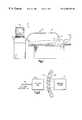
- a system for remotely interrogating a medical implant device in accordance with the inventionis generally designated 30 .
- the system 30includes a medical implant device 32 which is implanted in a living animal such as a human patient 34 .
- the medical implant device 32can be any of a wide variety of different types of devices including, for example, a stent, graft, artificial joint, etc.
- the device 32is configured to carry out or assist in carrying out a function within the patient 34 .
- the device 32prevents the closing of an arterial wall and permits the flow of blood therethrough.
- the device 32serves to couple blood flow between two separate ends of an artery.
- the device 32may instead consist of an artificial hip or knee which facilitates movement of the leg of the patient 34 .
- Other functionsinclude, but are not limited to, a hemodialysis shunt and spinal brace, for example.
- the device 32includes a sensing circuit (not shown in FIG. 1) which serves to sense a parameter associated with the function performed by the device.
- a sensing circuit(not shown in FIG. 1) which serves to sense a parameter associated with the function performed by the device.
- the sensormay be used to detect the degree of restenosis which occurs within the device 32 .
- the sensing circuitmay detect an amount of strain or displacement which occurs in an artificial hip or knee.
- the sensormay serve to sense the condition of the implant device in carrying out its intended function. For example, in the case of a pacemaker the sensor may detect the pulse rate.
- the system 30further includes interrogation instrumentation 36 for remotely interrogating the implant device 32 in order to evaluate the device function.
- the instrumentation 36includes an exciter/interrogator unit 38 which is positioned outside the patient 34 in close proximity to the implant device 32 .
- the exciter/interrogator unit 38serves to excite the sensing circuit within the device 32 .
- the sensing circuitis designed to have a variable impedance loading effect on the exciter/interrogator unit 38 , which varies in relation to the sensed parameter (e.g., blood flow, amount of restenosis, etc.).
- the exciter/interrogator unit 38is coupled via an electrical cable 40 to the main circuitry 42 included in the interrogation instrumentation 36 .
- the main circuitry 42includes suitable circuits for driving the exciter/interrogator unit 38 as described below, and for processing the output of the exciter/interrogator unit 38 in order to provide an output to an operator (e.g., display 44 ).
- the variable impedance loading effect of the device 32 on the exciter/interrogator unit 38is detected at different frequencies and processed to produce a display or the like indicative of the function performed using the device 32 .
- the present inventionpreferably utilizes magnetic coupling between the exciter/interrogator unit 38 and the implant device 32 .
- the sensing circuit in the device 32is a passive circuit designed to have an impedance loading effect on the exciter/interrogator unit 38 . In this manner, the sensing circuit can be a very simple, low cost circuit which is less prone to failure.
- the device 32does not require an active transmitter, mixer, amplifier, etc. as in other conventional devices.
- the sensing circuitcan be embedded within the device structure to reduce the amount of obstruction which occurs in the device and, for example, to increase performance.
- FIG. 2represents a simplified block diagram showing the positional relationship between the implant device 32 and the exciter/interrogator unit 38 .
- the exciter/interrogator unit 38preferably is a hand-held sized device which is held by a doctor, nurse or medical assistant in close proximity to the implant device 32 . Since the system 30 is non-invasive, the exciter/interrogator unit 38 may be placed adjacent the implant device 32 with the body of the patient (e.g., skin, muscle tissue, etc.), designated 50 , disposed therebetween.
- the preferred embodiment of the present inventionrelies on magnetic and/or electromagnetic coupling (represented by field lines 52 ) between the exciter/interrogator unit 38 and the implant device 32 to interrogate the device 32 non-invasively.
- the preferred embodiment of the present inventionintroduces sensor technology developed in the aerospace industry into medical implant devices.
- Commonly owned U.S. Pat. No. 5,581,248describes in detail how magnetic coupling between an interrogation circuit and a sensor coil, based on an impedance loading effect, can be used to interrogate an embedded sensor.
- no onehas thought to utilize such technology in medical implant devices.
- the entire disclosure of U.S. Pat. No. 5,581,248is incorporated herein by reference.
- FIG. 3illustrates the electrical configuration of the exciter/interrogator unit 38 and implant device 32 in more detail.
- the exciter/interrogator unit 38includes an exciter/interrogator coil 52 , a voltage controlled oscillator 54 , and a load sensing resistor 56 .
- the oscillator 54provides an excitation signal to the exciter/interrogator coil 52 and the load sensing resistor 56 which are coupled in series.
- the exciter/interrogator unit 38is coupled via the cable 40 to the main circuitry 42 which includes signal conditioning electronics 58 and a data processing and control section 60 .
- the data processing and control section 60produces a control signal on line 62 for controlling the frequency and the magnitude of the excitation signal that the oscillator 54 applies to the exciter/interrogator coil 52 .
- the exciter/interrogator coil 52 , sensing resistor 56 and oscillator 54provide a resonant exciter/interrogator circuit that is used to induce currents in a coil within the implant device 32 in order to perform interrogation.
- the implant device 32includes a sense coil 64 which is embedded in the structure of the implant device.
- the implant device 32may be any type of implant such as a stent or graft.
- the sense coil 64may be integrally secured to a surface of the stent or graft, for example, or even formed directly within the structure.
- the sense coil 64is part of a passive resonant sensing circuit 65 which includes, for example, a capacitor 66 and a sensing element 68 in electrical series with the sense coil 64 .
- the sensing element 68can be any sensor which produces a variable impedance (e.g., resistance, capacitance or inductance), or which produces an output that can be converted into a variable impedance that can change or modulate the impedance of one or more of the resonant circuit components.
- a variable impedancee.g., resistance, capacitance or inductance
- the sensing element 68is represented by a variable resistance which varies based on a sensed parameter.
- the sensing element 68may provide a capacitance, inductance and/or resistance which varies based on a sensed parameter.
- the sensing element 68 in combination with the sense coil 64 alone or together with one or more elements (e.g., capacitor 66 ) form a resonant sensing circuit 65 (e.g., LC or LRC)form a resonant sensing circuit 65 (e.g., LC or LRC), the benefits of the invention may be obtained.
- the sensing element 68can be any of a variety of known types of sensors which may be used to sense a functional parameter within the living body. Such parameters may include, but are not limited to, vascular parameters such as blood flow rate, blood pressure, oxygen content, cholesterol, restenosis, glucose level, temperature, etc.; hematology parameters such as blood gases, blood chemistry, hemoglobin content, etc., and skeletal/muscular parameters such as force, strain, displacement, etc.
- the sensing element 68itself may be characterized as an impedance based sensor whose resistance, capacitance and/or inductance varies directly with respect to frequency as a function of the sensed parameter, or another type sensor whose output can be converted into a variable impedance.
- Exemplary sensor typesinclude electrical, piezoelectric, sonic optical, microfluidic, chemical, membrane, thermal, magnetohydrodynamic, an NMR varient, magnetic, magnetostrictive, biological, microelectromechanical sensors (MEMs), etc.
- the sensing element 68may be a MEMs device whose impedance varies as a function of the amount or rate of blood flow through a stent or graft.
- the sensing element 68may be a surface acoustic wave (SAW) device which can detect blood flow.
- the sensing element 68may be a piezoelectric device within a stent or graft for detecting blood pressure.
- the sensing element 68may be included within the sense coil 64 itself.
- the embodiments of FIGS. 7 a, 8 a, 9 a, etc. as described belowincorporate the sense coil 64 within the tubular housing of a stent or graft. Changes in the amount of blood flow through the stent or graft and/or the occurrence of restenosis therein affect the overall inductance of the sense coil 64 .
- the sense coil 64 alone or in combination with one or more other sensing elements 68may be used to vary the impedance of the resonant sensing circuit based on the sensed parameter.
- the sensing circuit 65exhibits a resonant frequency which is defined as the frequency which is the point of maximum sensitivity to changes in the excitation current I P for a given change in the impedance of the sensing element 68 .
- the resonant frequency f sis determined by the sum total of the reactive elements of the circuit which includes the inductance of the sense coil 64 and the exciter/interrogator coil 52 , as well as the capacitance 66 (and parasitic capacitances C P1 and C P2 shown in FIG. 4) and the value of a coupling constant K.
- the amplitude of the current through the coil 64is also a function of the sensing element 68 , particularly at the resonant frequency of the sensing circuit 65 .
- the exciter/interrogator coil 52has an AC signal applied, current in the primary or exciter/interrogator coil 52 induces current in the secondary or sense coil 64 , as in an air gap transformer. This current in the sense coil 64 , however, is reflected back to the exciter/interrogator coil 52 by the mutual coupling of the two coils.
- the sensing resistor 56is used to detect the current in the exciter/interrogator coil 52 .
- the excitation frequencyis approximately at the resonant frequency of the sensing circuit 65
- the current in the exciter/interrogator coil 52changes maximally in relation to the value of the sensing element 68 .
- the condition of the sensing element 68can be determined as a function of the detected current in the exciter/interrogator coil 52 .
- the signal conditioning electronics 58amplifies the voltage developed across the sensing resistor 56 by the exciter/interrogator circuit current I P . This amplified voltage is then rectified and low pass filtered via a rectifier and low pass filter circuit 74 to provide a DC voltage output V dc .
- the control circuit 60uses the DC value to determine the state or output of the sensing element 68 .
- FIG. 4provides a more detailed circuit model of an exciter/interrogator unit 38 and the implant device 32 .
- the exciter/interrogator unit 38includes the exciter/interrogator coil 52 that has a determinable inductance L P .
- the coil 52 and associated components of the exciter/interrogator unit 38also will exhibit an overall parasitic capacitance, C P1 , that appears in parallel with the coil inductance.
- the exciter/interrogator unit 38further includes the variable frequency oscillator 54 and the sensing resistor 56 used to sense the primary or excitation current I P .
- all components in the exciter/interrogator unit 38are known quantities for each application.
- the resonant sensing circuit 65includes the sense coil 64 which has a determinable inductance, L S, in one embodiment; or in another embodiment an inductance which varies in relation to the sensed parameter. In such embodiment, the sense coil 64 itself forms part of the sensing element 68 .
- the sense coil 64also has an associated parasitic capacitance, which parasitic capacitance is in effect part of the capacitance C P2 which is a discrete capacitor selected to optimize the sensitivity of the device 32 to changes in the value of the sensing element 68 .
- the value of C P2can be selected, such as based on experimental data for specific circuits, to maximize the current I P induced in the exciter/interrogator unit 38 as a function of changes in the resistance of the sensing element 68 .
- the sensing circuit 65also includes the additional discrete capacitor 66 which is selected to adjust the frequency at which the change in current vs. change in sensing element resistance ratio is optimized.
- the sensing circuit 65all of the component parameters are known quantities except the coupling constant, K, and the value of the sensing element 68 output. Accounting for the coupling constant K as described more fully in the '248 patent, the DC output of the signal conditioning electronics 58 is indicative of the sensed parameter of the implant device 32 .
- FIG. 5is a graph showing in a representative manner a typical frequency response characteristic of the circuit of FIG. 4 .
- the sensed parametere.g., blood flow rate, degree of restenosis, etc.
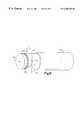
- FIG. 6 apresents a first embodiment of the present invention in which the medical implant device 32 is a stent.
- a stentis a round, spring-like device that provides mechanical support to the wall of a blood vessel such as an artery.
- the stent 32is inserted within a blood vessel 80 .
- the stent 32is tube shaped structure made up of a generally helical formed wall 82 .
- the stent 32prevents the walls of the blood vessel 80 from collapsing while providing a path 84 through which blood may flow.
- the wall 82typically is formed of stainless steel or some other material (e.g., a composite and/or plastic material) which is biocompatible within the body.
- the wall 82preferably is made of a non-conductive material or materials in one case, or a conductive material in another case.
- the wall 82preferably is made of a non-conductive material such as plastic.
- the sense coil 64is formed on an outer (or inner surface) of the tube shaped structure. Alternatively, the sense coil 64 may be embedded within the wall 82 .
- the sense coil 64is coupled via electrical conductors 86 and one or more through holes 87 to the remainder of the sensing circuit 65 which is formed on an inner surface of the wall structure 82 .
- the sensing element 68 in such an embodimentmay be a MEMs device whose capacitance and/or resistance varies as a function of the amount of restenosis which forms on the element 68 within the stent 32 .
- the sensing element 68may be a piezoelectric device which produces an impedance output which varies as a function of the pressure of the blood flowing within the stent 32 .
- the sense coil 64 and all or part of the remainder of the sensing circuit 65may be covered with a protective coating material to avoid corrosion or other related problems.
- the exciter/interrogator unit 38(FIG. 3) can be positioned outside the body of the patient in close proximity to the stent 32 .
- the exciter/interrogator unit 38serves to excite the sense coil 64 which in turn induces a current in the load resistor 56 which varies as a result of the variable impedance loading effect of the sensing circuit 65 with respect to frequency.
- the output of the sensing element 68varies based on the build up of restenosis, change in blood pressure, or other desired parameter, such variation may be detected remotely.
- FIG. 6 billustrates the equivalent circuit for the sensing circuit 65 in an embodiment where the sensing element 68 provides a resistance which varies in response to a sensed parameter.
- FIG. 6 cillustrates an equivalent circuit for the sensing circuit 65 in an embodiment where the sensing element 68 ′ produces an output which varies in capacitance based on the sensed parameter.
- the impedance loading effect of the sensing circuit 65varies in accordance with the sensed parameter by virtue of the resonance of the circuit being affected.
- FIG. 7 aAn alternative embodiment for a stent 32 is shown in FIG. 7 a.
- the helical shaped wall 82preferably is made of a molded plastic.
- the sense coil 64is made up of a conductive wire 92 embedded through several turns in the wall of the helix 82 as shown in cross-section in FIG. 7 b. Return wires 94 embedded in and traversing the helix 82 are provided to connect the respective ends of the coil 64 to the remainder of the resonant sensing circuit 65 mounted on the helix 82 as in the previous embodiment.
- the sense coil 64may serve as the frame about which the molded plastic helix 82 is formed.
- FIG. 7 cvaries slightly from that shown in FIGS. 7 a and 7 b.
- the return wires 94are formed on the inner surface of the helix 82 .
- Such embodimentsimplifies the manufacturing process by allowing the helix 82 to be formed without the return wires 94 traversing the helical turns in an embedded manner.
- FIG. 7 dillustrates generally the equivalent circuit for the stent 32 shown in FIGS. 7 a thru 7 c.
- the sensing element 68may be a resistive device as before, or some other type of sensor.
- the sense coil 64provides a means for magnetic coupling between the exciter/interrogator coil 52 and the resonant sensing circuit 65 .
- the impact of such variation on the impedance loading effect of the resonant sensing circuit 65 on the exciter/interrogator unit 38may be detected with respect to frequency.
- Such informationcan then be utilized in ascertaining the precise rate of blood flow, degree of restenosis, etc. via the data processing and control 60 .
- the particular type of sensing element 68will be dictated, of course, by the particular parameter of interest and the manner in which the output of the exciter/interrogator unit 38 is processed.
- FIG. 8 aillustrates another embodiment of a stent 32 which utilizes the conductive properties of a metal-type helix wall 82 .
- the helix wall 82is made of metal and therefore can itself form the sense coil 64 .
- the metal helixis electrically isolated via a non-conductive coating, for example.
- Each end 96 of the helixis connected to the remainder of the resonant sensing circuit 65 via return wires 94 as shown in phantom in FIG. 8 a.
- the resonant sensing circuit with the sensing element 68may be mounted on the inner surface of the stent 32 .
- FIG. 8 bdiagrammatically represents the electrical circuit of this particular embodiment.
- the inductance of the sense coil 64may itself vary as a function of the sensed parameter.
- the sense coil 64serves as a sensing element in addition and/or in place a discrete sensing element 68 .
- the sense coil 64 formed within the helixmay be considered an inductive element. It is combined with a discrete capacitor 66 and resistance 68 to form an LRC resonant sensing circuit 65 .
- the inductance of the sense coil 64depends directly on the magnetic permeability of the material inside it. Since iron strongly affects permeability, the amount of blood in the stent 32 as a fraction of the available volume (reduced by restenosis) will modulate the permeability and hence the resonant frequency of the sensing circuit 65 .
- the resonant frequencycan be determined by inductively coupling the stent 32 to the exciter/interrogator unit 38 via the externally generated swept frequency magnetic field. Knowledge of the resonant frequency then allows a determination of the inductance of the coil 64 . Since the value of inductance depends on the degree of restenosis, an estimate of its occlusion of the stent 32 can be made.
- FIGS. 7 c and 8 aeach include some type of direct linear connection via the return wires 94 between the sense coil 64 and the remainder of the resonant sensing circuit 65 . Such design may not be optimum from a biocompatibility standpoint or manufacturing standpoint.
- FIGS. 9 a and 9 brepresent an embodiment which eliminates the need for such return wires 94 . In this case, a double helix configuration is used to complete the resonant circuit.
- the helix wall 82is made of conductive metal and from one end to the other forms part of the coil 64 .
- the return wire 94is a second helix with the same pitch as the helix 82 but having an axial direction which is reversed relative to the helix 82 .
- the return wire 94is connected to one end of the helix 82 and returns to the other end where the resonant sensing circuit 65 can be closed with the capacitance 66 and resistance 68 . Electrically, such configuration doubles the inductance L of the coil 64 , and currents in the two helical sections 82 and 94 will produce magnetic fields which add rather than cancel. In the presence of a changing magnetic field, conversely, the current in the circuit 65 is doubled.
- the sense coil 64may be formed on a surface as in the embodiment of FIG. 6 a.
- the sense coil 64may be embedded in the structure as in the embodiments of FIGS. 7 b and 7 c, for example.
- FIG. 10illustrates an embodiment of the invention wherein the implant device 32 comprises a graft for joining separate ends 100 of a blood vessel.
- the graft 32is a tube shaped structure 102 made up of metal such as stainless steel, or a composite and/or plastic material.
- the graft 32is implanted within the patient by securing respective ends 100 of a blood vessel to corresponding ends of the graft 32 . Consequently, blood will flow through the interior of the graft 32 as represented by arrow 84 .
- the resonant sensing circuit 65can be any combination of a sense coil 64 , a capacitor 66 , a resistor 68 , etc.
- One or more of these componentspresents an impedance which varies as a function of the parameter to be sensed. Similar to the stent, it is desirable with the graft 32 to sense remotely the degree of restenosis and/or blood flow in the device.
- the frequency dependent impedance loading effect of the sensing circuitmay be detected externally using the exciter/interrogator unit 38 as previously described.
- FIG. 10The embodiment of FIG. 10 is similar to that of FIG. 6 a where the sense coil 64 is mounted on a surface of the tube structure 100 .
- the sensing element 68 and capacitor 66are mounted on an interior surface of the structure 100 .
- Electrical connections to the coil 64are provided by conductors 86 and vias 87 . Operation is fundamentally the same as described above in relation the stent embodiment.
- FIGS. 11 a thru 11 cillustrate an embodiment of a graft 32 analogous to the stent of FIGS. 7 a thru 7 c.
- the structure 100is made of a non-conductive material and the windings of the coil 64 are embedded directly within the tube.
- the structure 100may be molded plastic or the like with the coil 64 serving as a skeletal support.
- FIG. 12represents an embodiment of a graft 32 which uses a double helix structure similar to the stent in FIG. 9 a.
- the structure 100is uniform rather than helical, two separate helical wires 104 and 106 are embedded along the length of the tube 102 .
- the circuitis identical to that shown in FIG. 9 b.
- the inductance of the helical wires 104varies which changes the impedance loading effect on the exciter/interrogator unit 38 .
- FIG. 13illustrates yet another embodiment of a graft 32 (or stent) which is remotely interrogated in accordance with the present invention.
- a conventional devicemay be modified by placing a desired number of windings around the outer surface of the structure 102 to form the sense coil 64 .
- the capacitor 66 or other fixed componentsmay similarly be mounted on the outer surface.
- the sensing element 68is mounted on the inside surface and connected through vias 87 to the coil 64 and capacitor 66 to form the LRC resonant sensing circuit 65 .
- the sensing element 68may be mounted on the outer surface also, provided the sensing element is capable of sensing the desired parameter through the structure 102 .
- a laminate sheath 110is applied over the outer surface of the structure 102 and heated to form an integrated graft 32 .
- the sensing circuit 65can then be interrogated in the same manner described above in connection with the other embodiments.
Landscapes
- Health & Medical Sciences (AREA)
- Life Sciences & Earth Sciences (AREA)
- Molecular Biology (AREA)
- Surgery (AREA)
- Biophysics (AREA)
- Pathology (AREA)
- Engineering & Computer Science (AREA)
- Biomedical Technology (AREA)
- Heart & Thoracic Surgery (AREA)
- Medical Informatics (AREA)
- Veterinary Medicine (AREA)
- Physics & Mathematics (AREA)
- Animal Behavior & Ethology (AREA)
- General Health & Medical Sciences (AREA)
- Public Health (AREA)
- Vascular Medicine (AREA)
- Cardiology (AREA)
- Nuclear Medicine, Radiotherapy & Molecular Imaging (AREA)
- Radiology & Medical Imaging (AREA)
- Physiology (AREA)
- Hematology (AREA)
- Prostheses (AREA)
Abstract
Description
Claims (19)
Priority Applications (6)
| Application Number | Priority Date | Filing Date | Title |
|---|---|---|---|
| US09/275,308US6206835B1 (en) | 1999-03-24 | 1999-03-24 | Remotely interrogated diagnostic implant device with electrically passive sensor |
| AU39123/00AAU3912300A (en) | 1999-03-24 | 2000-03-23 | Remotely interrogated diagnostic implant device with electrically passive sensor |
| EP00918289AEP1162914A1 (en) | 1999-03-24 | 2000-03-23 | Remotely interrogated diagnostic implant device with electrically passive sensor |
| PCT/US2000/007694WO2000056210A1 (en) | 1999-03-24 | 2000-03-23 | Remotely interrogated diagnostic implant device with electrically passive sensor |
| JP2000606120AJP2003532440A (en) | 1999-03-24 | 2000-03-23 | Remotely queried diagnostic implant device with electrically passive sensors |
| CA002364869ACA2364869A1 (en) | 1999-03-24 | 2000-03-23 | Remotely interrogated diagnostic implant device with electrically passive sensor |
Applications Claiming Priority (1)
| Application Number | Priority Date | Filing Date | Title |
|---|---|---|---|
| US09/275,308US6206835B1 (en) | 1999-03-24 | 1999-03-24 | Remotely interrogated diagnostic implant device with electrically passive sensor |
Publications (1)
| Publication Number | Publication Date |
|---|---|
| US6206835B1true US6206835B1 (en) | 2001-03-27 |
Family
ID=23051740
Family Applications (1)
| Application Number | Title | Priority Date | Filing Date |
|---|---|---|---|
| US09/275,308Expired - Fee RelatedUS6206835B1 (en) | 1999-03-24 | 1999-03-24 | Remotely interrogated diagnostic implant device with electrically passive sensor |
Country Status (1)
| Country | Link |
|---|---|
| US (1) | US6206835B1 (en) |
Cited By (170)
| Publication number | Priority date | Publication date | Assignee | Title |
|---|---|---|---|---|
| WO2002030331A1 (en)* | 2000-10-11 | 2002-04-18 | Uab Research Foundation | Mri stent |
| US20020107445A1 (en)* | 1999-03-11 | 2002-08-08 | Assaf Govari | Implantable and insertable passive tags |
| US6442413B1 (en)* | 2000-05-15 | 2002-08-27 | James H. Silver | Implantable sensor |
| US20020183628A1 (en)* | 2001-06-05 | 2002-12-05 | Sanford Reich | Pressure sensing endograft |
| US20020183829A1 (en)* | 2001-03-20 | 2002-12-05 | Claas Doscher | Material for medical stents and device for the intracorporeal inductive heating of these stents |
| US20030004411A1 (en)* | 1999-03-11 | 2003-01-02 | Assaf Govari | Invasive medical device with position sensing and display |
| US20030018246A1 (en)* | 1999-03-11 | 2003-01-23 | Assaf Govari | Guidance of invasive medical procedures using implantable tags |
| US20030023161A1 (en)* | 1999-03-11 | 2003-01-30 | Assaf Govari | Position sensing system with integral location pad and position display |
| US20030040291A1 (en)* | 2001-08-21 | 2003-02-27 | Brewer Samuel Joseph | Transmitter system for wireless communication with implanted devices |
| US20030114735A1 (en)* | 2000-05-15 | 2003-06-19 | Silver James H. | Implantable, retrievable sensors and immunosensors |
| US20030136417A1 (en)* | 2002-01-22 | 2003-07-24 | Michael Fonseca | Implantable wireless sensor |
| WO2002076289A3 (en)* | 2001-03-27 | 2003-11-20 | Aron Z Kain | Wireless system for measuring distension in flexible tubes |
| US20030220592A1 (en)* | 2002-03-18 | 2003-11-27 | Dornier Medtech Systems Gmbh | Apparatus and method for producing bipolar acoustic pulses |
| US6682490B2 (en) | 2001-12-03 | 2004-01-27 | The Cleveland Clinic Foundation | Apparatus and method for monitoring a condition inside a body cavity |
| US20040039329A1 (en)* | 2002-05-24 | 2004-02-26 | Dornier Medtech Systems Gmbh | Method and apparatus for transferring medically effective substances into cells |
| US20040049428A1 (en)* | 2002-09-05 | 2004-03-11 | Soehnlen John Pius | Wireless environmental sensing in packaging applications |
| US20040054385A1 (en)* | 2000-06-29 | 2004-03-18 | Lesho Jeffery C. | Implanted sensor processing system and method |
| US20040116981A1 (en)* | 2002-12-13 | 2004-06-17 | Cardiac Pacemakers, Inc. | Device communications of an implantable medical device and an external system |
| US20040122489A1 (en)* | 2002-12-23 | 2004-06-24 | Cardiac Pacemakers, Inc. | Implantable medical device having long-term wireless capabilities |
| US20040122488A1 (en)* | 2002-12-23 | 2004-06-24 | Cardiac Pacemakers, Inc. | Method and apparatus for enabling data communication between an implantable medical device and a patient management system |
| US20040128161A1 (en)* | 2002-12-27 | 2004-07-01 | Mazar Scott T. | System and method for ad hoc communications with an implantable medical device |
| US20040149294A1 (en)* | 2002-12-16 | 2004-08-05 | Gianchandani Yogesh B. | Assembly and planar structure for use therein which is expandable into a 3-D structure such as a stent and device for making the planar structure |
| US20040176797A1 (en)* | 2003-03-04 | 2004-09-09 | Nmt Medical, Inc. | Magnetic attachment systems |
| US20040215049A1 (en)* | 2003-01-24 | 2004-10-28 | Proteus Biomedical, Inc. | Method and system for remote hemodynamic monitoring |
| US20040225208A1 (en)* | 1999-05-27 | 2004-11-11 | Royce Johnson | System for combined transcutaneous blood gas monitoring and vacuum assisted wound closure |
| US20040254483A1 (en)* | 2003-01-24 | 2004-12-16 | Proteus Biomedical, Inc. | Methods and systems for measuring cardiac parameters |
| US20050004478A1 (en)* | 2001-05-31 | 2005-01-06 | Fitz Matthew J. | Implantable device for monitoring aneurysm sac parameters |
| US20050004324A1 (en)* | 2003-05-21 | 2005-01-06 | Ward Robert S. | Permselective structurally robust membrane material |
| US20050015014A1 (en)* | 2002-01-22 | 2005-01-20 | Michael Fonseca | Implantable wireless sensor for pressure measurement within the heart |
| US20050019366A1 (en)* | 2002-12-31 | 2005-01-27 | Zeldis Jerome B. | Drug-coated stents and methods of use therefor |
| US20050027175A1 (en)* | 2003-07-31 | 2005-02-03 | Zhongping Yang | Implantable biosensor |
| US20050027192A1 (en)* | 2003-07-29 | 2005-02-03 | Assaf Govari | Energy transfer amplification for intrabody devices |
| US20050080346A1 (en)* | 2002-12-16 | 2005-04-14 | The Regents Of The University Of Michigan | Antenna stent device for wireless, intraluminal monitoring |
| US20050096562A1 (en)* | 2003-11-05 | 2005-05-05 | Delalic Z. J. | Implantable telemetric monitoring system, apparatus, and method |
| US20050101946A1 (en)* | 2003-11-11 | 2005-05-12 | Biosense Webster Inc. | Externally applied RF for pulmonary vein isolation |
| US20050107866A1 (en)* | 2002-06-07 | 2005-05-19 | Brown Peter S. | Endovascular graft with pressor and attachment methods |
| WO2005058166A1 (en) | 2003-12-15 | 2005-06-30 | Imperial College Innovations Ltd. | Acoustic wave devices |
| US20050187482A1 (en)* | 2003-09-16 | 2005-08-25 | O'brien David | Implantable wireless sensor |
| US20050240110A1 (en)* | 2004-04-21 | 2005-10-27 | Honeywell International, Inc. | Passive and wireless in-vivo acoustic wave flow sensor |
| US20050277839A1 (en)* | 2004-06-10 | 2005-12-15 | Honeywell International, Inc. | Wireless flow measurement in arterial stent |
| US6978182B2 (en) | 2002-12-27 | 2005-12-20 | Cardiac Pacemakers, Inc. | Advanced patient management system including interrogator/transceiver unit |
| US20060024803A1 (en)* | 2001-02-19 | 2006-02-02 | Dornier Medtech Systems Gmbh | Method and device for ultrasonic inoculation of biological cell material |
| US20060030914A1 (en)* | 2002-01-18 | 2006-02-09 | Apsara Medical Corporation | System, method and apparatus for evaluating tissue temperature |
| US7009511B2 (en) | 2002-12-17 | 2006-03-07 | Cardiac Pacemakers, Inc. | Repeater device for communications with an implantable medical device |
| US20060058588A1 (en)* | 2004-09-02 | 2006-03-16 | Proteus Biomedical, Inc. | Methods and apparatus for tissue activation and monitoring |
| US7025778B2 (en) | 2002-06-07 | 2006-04-11 | Endovascular Technologies, Inc. | Endovascular graft with pressure, temperature, flow and voltage sensors |
| US20060079740A1 (en)* | 2000-05-15 | 2006-04-13 | Silver James H | Sensors for detecting substances indicative of stroke, ischemia, or myocardial infarction |
| US20060089856A1 (en)* | 2004-10-21 | 2006-04-27 | Cardiac Pacemakers | Integrated pharmaceutical dispensing and patient management monitoring |
| US20060089592A1 (en)* | 2004-10-21 | 2006-04-27 | Cardiac Pacemakers, Inc. | Systems and methods for drug therapy enhancement using expected pharmacodynamic models |
| US20060116602A1 (en)* | 2004-12-01 | 2006-06-01 | Alden Dana A | Medical sensing device and system |
| WO2006084156A2 (en) | 2005-02-04 | 2006-08-10 | C. R. Bard, Inc. | Vascular filter with sensing capability |
| US20060177956A1 (en)* | 2005-02-10 | 2006-08-10 | Cardiomems, Inc. | Method of manufacturing a hermetic chamber with electrical feedthroughs |
| US20060183871A1 (en)* | 2003-05-21 | 2006-08-17 | Ward Robert S | Biosensor membrane material |
| US20060191354A1 (en)* | 2005-02-25 | 2006-08-31 | Drager Medical Ag & Co. Kg | Device for measuring a volume flow with inductive coupling |
| US20060200031A1 (en)* | 2005-03-03 | 2006-09-07 | Jason White | Apparatus and method for sensor deployment and fixation |
| US20060200220A1 (en)* | 2002-06-07 | 2006-09-07 | Brown Peter S | Endovascular graft with sensors design and attachment methods |
| US20060271199A1 (en)* | 2005-05-20 | 2006-11-30 | Johnson Lanny L | Navigational markers in implants |
| US20060283007A1 (en)* | 2005-06-21 | 2006-12-21 | Cardiomems, Inc. | Method of manufacturing implantable wireless sensor for in vivo pressure measurement |
| US20060287602A1 (en)* | 2005-06-21 | 2006-12-21 | Cardiomems, Inc. | Implantable wireless sensor for in vivo pressure measurement |
| US20060293718A1 (en)* | 2005-06-24 | 2006-12-28 | Kenergy, Inc. | Double helical antenna assembly for a wireless intravascular medical device |
| US20070011028A1 (en)* | 2005-07-05 | 2007-01-11 | Cardiac Pacemakers, Inc. | Optimization of timing for data collection and analysis in advanced patient management system |
| US20070023424A1 (en)* | 2005-07-26 | 2007-02-01 | Boston Scientific Scimed, Inc. | Resonator for medical device |
| US7181261B2 (en)* | 2000-05-15 | 2007-02-20 | Silver James H | Implantable, retrievable, thrombus minimizing sensors |
| WO2007033062A1 (en)* | 2005-09-13 | 2007-03-22 | Honeywell International Inc. | Wireless capacitance pressure sensor |
| US7200439B2 (en) | 2003-01-24 | 2007-04-03 | Proteus Biomedical, Inc. | Method and apparatus for enhancing cardiac pacing |
| US20070118038A1 (en)* | 2005-11-23 | 2007-05-24 | Vital Sensors Inc. | Implantable device for telemetric measurement of blood pressure/temperature within the heart |
| US20070143048A1 (en)* | 2005-12-02 | 2007-06-21 | Semiconductor Energy Laboratory Co., Ltd. | Test method of microsctructure body and micromachine |
| US20070151390A1 (en)* | 2005-03-30 | 2007-07-05 | Blumenkranz Stephen J | Force and Torque Sensing For Surgical Instruments |
| US7245117B1 (en) | 2004-11-01 | 2007-07-17 | Cardiomems, Inc. | Communicating with implanted wireless sensor |
| US20070219639A1 (en)* | 2006-03-14 | 2007-09-20 | Mako Surgical Corporation | Prosthetic device and system and method for implanting prosthetic device |
| US20070247138A1 (en)* | 2004-11-01 | 2007-10-25 | Miller Donald J | Communicating with an implanted wireless sensor |
| US20070261497A1 (en)* | 2005-02-10 | 2007-11-15 | Cardiomems, Inc. | Hermatic Chamber With Electrical Feedthroughs |
| US20070265690A1 (en)* | 2006-05-12 | 2007-11-15 | Yoav Lichtenstein | Position tracking of passive resonance-based transponders |
| US20070276294A1 (en)* | 2004-07-08 | 2007-11-29 | Munish Gupta | Strain monitoring system and apparatus |
| US20080077016A1 (en)* | 2006-09-22 | 2008-03-27 | Integrated Sensing Systems, Inc. | Monitoring system having implantable inductive sensor |
| US20080081965A1 (en)* | 2006-09-29 | 2008-04-03 | Philometron, Inc. | Foreign body response detection in an implanted device |
| US20080108698A1 (en)* | 2004-10-21 | 2008-05-08 | Oy Elmomed Ltd | Nutrient Supplement and Use of the Same |
| US20080176271A1 (en)* | 2000-05-15 | 2008-07-24 | Silver James H | Sensors for detecting substances indicative of stroke, ischemia, infection or inflammation |
| WO2008094489A1 (en)* | 2007-01-26 | 2008-08-07 | Nunez Anthony I | Arterial pressure sensing device |
| US20080202246A1 (en)* | 2007-02-22 | 2008-08-28 | Tetsuya Suzuki | Vibration detecting device |
| US20080221419A1 (en)* | 2005-12-08 | 2008-09-11 | Cardio Art Technologies Ltd. | Method and system for monitoring a health condition |
| US20080267927A1 (en)* | 2004-12-15 | 2008-10-30 | Dornier Medtech Systems Gmbh | Methods for improving cell therapy and tissue regeneration in patients with cardiovascular diseases by means of shockwaves |
| US20080294218A1 (en)* | 2005-03-31 | 2008-11-27 | Proteus Biomedical, Inc. | Automated Optimization of Multi-Electrode Pacing for Cardiac Resynchronization |
| US20080306394A1 (en)* | 2005-08-12 | 2008-12-11 | Zdeblick Mark J | Measuring Conduction Velocity Using One or More Satellite Devices |
| US20090025459A1 (en)* | 2007-07-23 | 2009-01-29 | Cardiac Pacemakers, Inc. | Implantable viscosity monitoring device and method therefor |
| US20090051445A1 (en)* | 2007-08-22 | 2009-02-26 | Ellis Michael G | Loosely-coupled oscillator |
| US20090189741A1 (en)* | 2007-03-15 | 2009-07-30 | Endotronix, Inc. | Wireless sensor reader |
| US7575550B1 (en) | 1999-03-11 | 2009-08-18 | Biosense, Inc. | Position sensing based on ultrasound emission |
| US20090221882A1 (en)* | 2005-12-08 | 2009-09-03 | Dan Gur Furman | Implantable Biosensor Assembly and Health Monitoring system and Method including same |
| US20090299447A1 (en)* | 2005-07-01 | 2009-12-03 | Marc Jensen | Deployable epicardial electrode and sensor array |
| US20100022894A1 (en)* | 2008-07-28 | 2010-01-28 | Biotronik Vi Patent Ag | Intravascular Measurement |
| US20100058583A1 (en)* | 2005-06-21 | 2010-03-11 | Florent Cros | Method of manufacturing implantable wireless sensor for in vivo pressure measurement |
| WO2010006592A3 (en)* | 2008-07-18 | 2010-03-11 | Neue Magnetodyn Gmbh | System for recording measured values in or on an organism, and method for producing a component of this system |
| US7682313B2 (en) | 2005-11-23 | 2010-03-23 | Vital Sensors Holding Company, Inc. | Implantable pressure monitor |
| US20100076563A1 (en)* | 2008-09-19 | 2010-03-25 | Smith & Nephew, Inc. | Operatively tuning implants for increased performance |
| US20100087835A1 (en)* | 2005-12-30 | 2010-04-08 | Blumenkranz Stephen J | Wireless force sensor on a distal portion of a surgical instrument and method |
| US20100137724A1 (en)* | 2005-06-27 | 2010-06-03 | Sense A/S | Method and an apparatus for determination of blood pressure |
| US20100152562A1 (en)* | 2005-02-08 | 2010-06-17 | Abbott Diabetes Care Inc. | RF Tag on Test Strips, Test Strip Vials and Boxes |
| US20100204766A1 (en)* | 2005-12-22 | 2010-08-12 | Mark Zdeblick | Implantable integrated circuit |
| US20100213057A1 (en)* | 2009-02-26 | 2010-08-26 | Benjamin Feldman | Self-Powered Analyte Sensor |
| US20100308974A1 (en)* | 2007-03-15 | 2010-12-09 | Rowland Harry D | Wireless sensor reader |
| US20100318163A1 (en)* | 2009-04-29 | 2010-12-16 | Mark Zdeblick | Methods and apparatus for leads for implantable devices |
| US20110022113A1 (en)* | 2008-12-02 | 2011-01-27 | Mark Zdeblick | Analyzer Compatible Communication Protocol |
| US20110034964A1 (en)* | 2008-02-28 | 2011-02-10 | Yafei Bi | Integrated Circuit Implementation and Fault Control System, Device, and Method |
| US7918800B1 (en) | 2004-10-08 | 2011-04-05 | Endovascular Technologies, Inc. | Aneurysm sensing devices and delivery systems |
| US20110082530A1 (en)* | 2009-04-02 | 2011-04-07 | Mark Zdeblick | Method and Apparatus for Implantable Lead |
| US20110224529A1 (en)* | 2008-11-18 | 2011-09-15 | Sense A/S | Methods, apparatus and sensor for measurement of cardiovascular quantities |
| US8021307B2 (en) | 2005-03-03 | 2011-09-20 | Cardiomems, Inc. | Apparatus and method for sensor deployment and fixation |
| US8072310B1 (en) | 2007-06-05 | 2011-12-06 | Pulsed Indigo Inc. | System for detecting and measuring parameters of passive transponders |
| US8317776B2 (en) | 2007-12-18 | 2012-11-27 | The Invention Science Fund I, Llc | Circulatory monitoring systems and methods |
| US20120310139A1 (en)* | 2009-11-09 | 2012-12-06 | Medtronic Xomed, Inc. | Adjustable valve setting with motor control |
| US8355784B2 (en) | 2011-05-13 | 2013-01-15 | Medtronic, Inc. | Dynamic representation of multipolar leads in a programmer interface |
| US8409132B2 (en) | 2007-12-18 | 2013-04-02 | The Invention Science Fund I, Llc | Treatment indications informed by a priori implant information |
| US20130131500A1 (en)* | 2011-11-18 | 2013-05-23 | Covidien Lp | In-situ proximity recognition apparatus |
| EP2265164A4 (en)* | 2008-04-01 | 2013-10-02 | Cardiomems Inc | Strain monitoring system and apparatus |
| US8636670B2 (en) | 2008-05-13 | 2014-01-28 | The Invention Science Fund I, Llc | Circulatory monitoring systems and methods |
| US8712549B2 (en) | 2002-12-11 | 2014-04-29 | Proteus Digital Health, Inc. | Method and system for monitoring and treating hemodynamic parameters |
| US8718770B2 (en) | 2010-10-21 | 2014-05-06 | Medtronic, Inc. | Capture threshold measurement for selection of pacing vector |
| US8786049B2 (en) | 2009-07-23 | 2014-07-22 | Proteus Digital Health, Inc. | Solid-state thin-film capacitor |
| US8870787B2 (en) | 2003-09-16 | 2014-10-28 | Cardiomems, Inc. | Ventricular shunt system and method |
| US8896324B2 (en) | 2003-09-16 | 2014-11-25 | Cardiomems, Inc. | System, apparatus, and method for in-vivo assessment of relative position of an implant |
| US20140360598A1 (en)* | 2011-01-27 | 2014-12-11 | Medtronic Xomed, Inc. | Reading and adjusting tool for hydrocephalus shunt valve |
| US9278033B2 (en) | 2011-11-22 | 2016-03-08 | Kimberly-Clark Worldwide, Inc. | Contactless passive sensing for absorbent articles |
| WO2016050972A1 (en)* | 2014-10-03 | 2016-04-07 | Centre National De La Recherche Scientifique | Medical device provided with sensors having variable impedance |
| US9489831B2 (en) | 2007-03-15 | 2016-11-08 | Endotronix, Inc. | Wireless sensor reader |
| EP3093626A1 (en) | 2015-05-12 | 2016-11-16 | Universita' degli studi di Brescia | System and method for the measurement of quantities |
| US9703751B2 (en) | 2012-11-07 | 2017-07-11 | Nokia Technologies Oy | Apparatus and sensors for attachment to the apparatus |
| WO2017174688A1 (en) | 2016-04-06 | 2017-10-12 | Instent | Medical device provided with sensors |
| WO2018013725A1 (en) | 2016-07-12 | 2018-01-18 | Graftworx, Inc. | System and method for measuring blood flow parameters in a blood vessel having an endovascular prosthesis |
| US9996712B2 (en) | 2015-09-02 | 2018-06-12 | Endotronix, Inc. | Self test device and method for wireless sensor reader |
| US10003862B2 (en) | 2007-03-15 | 2018-06-19 | Endotronix, Inc. | Wireless sensor reader |
| US10117614B2 (en) | 2006-02-28 | 2018-11-06 | Abbott Diabetes Care Inc. | Method and system for providing continuous calibration of implantable analyte sensors |
| US10206592B2 (en) | 2012-09-14 | 2019-02-19 | Endotronix, Inc. | Pressure sensor, anchor, delivery system and method |
| US10240994B1 (en) | 2016-08-26 | 2019-03-26 | W. L. Gore & Associates, Inc. | Wireless cylindrical shell passive LC sensor |
| US10307067B1 (en) | 2016-08-26 | 2019-06-04 | W. L. Gore & Associates, Inc. | Wireless LC sensor reader |
| US10357180B2 (en) | 2014-01-16 | 2019-07-23 | D.T.R. Dermal Therapy Research Inc. | Health monitoring system |
| US10429252B1 (en) | 2016-08-26 | 2019-10-01 | W. L. Gore & Associates, Inc. | Flexible capacitive pressure sensor |
| US10430624B2 (en) | 2017-02-24 | 2019-10-01 | Endotronix, Inc. | Wireless sensor reader assembly |
| US10662513B2 (en) | 2016-07-26 | 2020-05-26 | Verkko Biomedical, LLC | Dynamic, non-homogenous shape memory alloys |
| EP3463082B1 (en)* | 2016-11-29 | 2020-07-29 | Foundry Innovation & Research 1, Ltd. | Wireless resonant circuit and variable inductance vascular implants for monitoring patient vasculature system |
| US10806428B2 (en) | 2015-02-12 | 2020-10-20 | Foundry Innovation & Research 1, Ltd. | Implantable devices and related methods for heart failure monitoring |
| US10814980B2 (en) | 2017-09-02 | 2020-10-27 | Precision Drone Services Intellectual Property, Llc | Distribution assembly for an aerial vehicle |
| US10912482B2 (en) | 2015-10-23 | 2021-02-09 | Sensome SAS | Method for determining at least one type and/or condition of cells and system |
| US10993669B2 (en) | 2017-04-20 | 2021-05-04 | Endotronix, Inc. | Anchoring system for a catheter delivered device |
| US11039813B2 (en) | 2015-08-03 | 2021-06-22 | Foundry Innovation & Research 1, Ltd. | Devices and methods for measurement of Vena Cava dimensions, pressure and oxygen saturation |
| US11051712B2 (en)* | 2016-02-09 | 2021-07-06 | Verily Life Sciences Llc | Systems and methods for determining the location and orientation of implanted devices |
| US11206992B2 (en) | 2016-08-11 | 2021-12-28 | Foundry Innovation & Research 1, Ltd. | Wireless resonant circuit and variable inductance vascular monitoring implants and anchoring structures therefore |
| WO2021260428A1 (en) | 2020-06-26 | 2021-12-30 | Surgiconcept Ltd | Intraosseous implantable microsensors and methods of use |
| US11284840B1 (en) | 2016-08-26 | 2022-03-29 | W. L. Gore & Associates, Inc. | Calibrating passive LC sensor |
| EP3988061A1 (en)* | 2013-03-15 | 2022-04-27 | Canary Medical Inc. | Stent monitoring assembly and method of use thereof |
| US11406274B2 (en) | 2016-09-12 | 2022-08-09 | Alio, Inc. | Wearable device with multimodal diagnostics |
| US20220354429A1 (en)* | 2021-05-05 | 2022-11-10 | Boston Scientific Scimed, Inc. | Medical device with sensing capabilities |
| US11540772B2 (en) | 2016-03-23 | 2023-01-03 | Canary Medical Inc. | Implantable reporting processor for an alert implant |
| US11564596B2 (en) | 2016-08-11 | 2023-01-31 | Foundry Innovation & Research 1, Ltd. | Systems and methods for patient fluid management |
| US11568990B2 (en) | 2016-11-21 | 2023-01-31 | Sensome SAS | Characterizing and identifying biological structure |
| US11596308B2 (en) | 2014-09-17 | 2023-03-07 | Canary Medical Inc. | Devices, systems and methods for using and monitoring medical devices |
| US11615257B2 (en) | 2017-02-24 | 2023-03-28 | Endotronix, Inc. | Method for communicating with implant devices |
| US11622684B2 (en) | 2017-07-19 | 2023-04-11 | Endotronix, Inc. | Physiological monitoring system |
| US11701018B2 (en) | 2016-08-11 | 2023-07-18 | Foundry Innovation & Research 1, Ltd. | Wireless resonant circuit and variable inductance vascular monitoring implants and anchoring structures therefore |
| US11779238B2 (en) | 2017-05-31 | 2023-10-10 | Foundry Innovation & Research 1, Ltd. | Implantable sensors for vascular monitoring |
| US11779243B2 (en)* | 2019-01-07 | 2023-10-10 | Align Technology, Inc. | Customized aligner change indicator |
| CN117319958A (en)* | 2023-11-28 | 2023-12-29 | 浙江龙感科技有限公司成都分公司 | Passive wireless sensing control system and control method |
| US11911141B2 (en) | 2014-06-25 | 2024-02-27 | Canary Medical Switzerland Ag | Devices, systems and methods for using and monitoring tubes in body passageways |
| US11944495B2 (en) | 2017-05-31 | 2024-04-02 | Foundry Innovation & Research 1, Ltd. | Implantable ultrasonic vascular sensor |
| US11998348B2 (en) | 2014-06-25 | 2024-06-04 | Canary Medical Switzerland Ag | Devices, systems and methods for using and monitoring heart valves |
| US11998349B2 (en) | 2013-03-15 | 2024-06-04 | Canary Medical Inc. | Devices, systems and methods for monitoring hip replacements |
| US12097044B2 (en) | 2013-06-23 | 2024-09-24 | Canary Medical Inc. | Devices, systems and methods for monitoring knee replacements |
| US12138181B2 (en) | 2019-06-06 | 2024-11-12 | Canary Medical Inc. | Intelligent joint prosthesis |
| US12142376B2 (en) | 2019-06-06 | 2024-11-12 | Canary Medical Inc. | Intelligent joint prosthesis |
| US12440153B2 (en) | 2021-12-06 | 2025-10-14 | Canary Medical Inc. | Implantable reporting processor for an alert implant |
Citations (31)
| Publication number | Priority date | Publication date | Assignee | Title |
|---|---|---|---|---|
| US3218638A (en)* | 1962-05-29 | 1965-11-16 | William M Honig | Wireless passive biological telemetry system |
| US4026276A (en)* | 1976-04-05 | 1977-05-31 | The Johns Hopkins University | Intracranial pressure monitor |
| US4114606A (en) | 1976-11-12 | 1978-09-19 | The Johns Hopkins University | Monitoring apparatus for resonant circuit intracranial pressure implants |
| US4227407A (en) | 1978-11-30 | 1980-10-14 | Cornell Research Foundation, Inc. | Volume flow measurement system |
| US4352960A (en) | 1980-09-30 | 1982-10-05 | Baptist Medical Center Of Oklahoma, Inc. | Magnetic transcutaneous mount for external device of an associated implant |
| US4361153A (en)* | 1980-05-27 | 1982-11-30 | Cordis Corporation | Implant telemetry system |
| US4453537A (en) | 1981-08-04 | 1984-06-12 | Spitzer Daniel E | Apparatus for powering a body implant device |
| US4528987A (en)* | 1983-09-28 | 1985-07-16 | Cordis Corporation | Apparatus and process for communicating an electrogram |
| US5305758A (en) | 1991-04-12 | 1994-04-26 | Tetrad Corporation | Ultrasonic apparatus for use in obtaining blood flow information |
| US5306644A (en) | 1988-09-29 | 1994-04-26 | Hewlett-Packard Company | Mass sensor method for measuring analytes in a sample |
| US5358514A (en) | 1991-12-18 | 1994-10-25 | Alfred E. Mann Foundation For Scientific Research | Implantable microdevice with self-attaching electrodes |
| US5372133A (en) | 1992-02-05 | 1994-12-13 | N.V. Nederlandsche Apparatenfabriek Nedap | Implantable biomedical sensor device, suitable in particular for measuring the concentration of glucose |
| US5411551A (en) | 1992-08-05 | 1995-05-02 | Ultrasonic Sensing And Monitoring Systems, Inc. | Stent assembly with sensor |
| US5620475A (en) | 1994-04-25 | 1997-04-15 | Siemens Elema Ab | Extracorporeally controllable medical implant and method for operating same |
| US5626630A (en)* | 1994-10-13 | 1997-05-06 | Ael Industries, Inc. | Medical telemetry system using an implanted passive transponder |
| US5663507A (en) | 1996-03-18 | 1997-09-02 | President And Fellows At Harvard College | Semiconductor piezoelectric strain measuring transducer |
| US5709225A (en) | 1994-09-22 | 1998-01-20 | Pacesetter Ab | Combined magnetic field detector and activity detector employing a capacitive sensor, for a medical implant |
| US5720771A (en) | 1995-08-02 | 1998-02-24 | Pacesetter, Inc. | Method and apparatus for monitoring physiological data from an implantable medical device |
| US5735887A (en) | 1996-12-10 | 1998-04-07 | Exonix Corporation | Closed-loop, RF-coupled implanted medical device |
| US5741315A (en) | 1996-03-22 | 1998-04-21 | Ela Medical S.A. | Apparatus for receiving telemetry signals from active implantable medical devices |
| US5749909A (en) | 1996-11-07 | 1998-05-12 | Sulzer Intermedics Inc. | Transcutaneous energy coupling using piezoelectric device |
| WO1998029030A1 (en) | 1997-01-03 | 1998-07-09 | Biosense Inc. | Pressure-sensing stent |
| US5807258A (en) | 1997-10-14 | 1998-09-15 | Cimochowski; George E. | Ultrasonic sensors for monitoring the condition of a vascular graft |
| US5833603A (en) | 1996-03-13 | 1998-11-10 | Lipomatrix, Inc. | Implantable biosensing transponder |
| US5861019A (en)* | 1997-07-25 | 1999-01-19 | Medtronic Inc. | Implantable medical device microstrip telemetry antenna |
| US5891180A (en) | 1998-04-29 | 1999-04-06 | Medtronic Inc. | Interrogation of an implantable medical device using audible sound communication |
| WO1999042176A1 (en) | 1998-02-23 | 1999-08-26 | Vascusense, Inc. | Endoluminal implant with therapeutic and diagnostic capability |
| WO1999042039A1 (en) | 1998-02-23 | 1999-08-26 | Vascusense, Inc. | Implantable therapeutic device and method |
| US5967986A (en) | 1997-11-25 | 1999-10-19 | Vascusense, Inc. | Endoluminal implant with fluid flow sensing capability |
| US5972029A (en) | 1997-05-13 | 1999-10-26 | Fuisz Technologies Ltd. | Remotely operable stent |
| US6015386A (en) | 1998-05-07 | 2000-01-18 | Bpm Devices, Inc. | System including an implantable device and methods of use for determining blood pressure and other blood parameters of a living being |
- 1999
- 1999-03-24USUS09/275,308patent/US6206835B1/ennot_activeExpired - Fee Related
Patent Citations (32)
| Publication number | Priority date | Publication date | Assignee | Title |
|---|---|---|---|---|
| US3218638A (en)* | 1962-05-29 | 1965-11-16 | William M Honig | Wireless passive biological telemetry system |
| US4026276A (en)* | 1976-04-05 | 1977-05-31 | The Johns Hopkins University | Intracranial pressure monitor |
| US4114606A (en) | 1976-11-12 | 1978-09-19 | The Johns Hopkins University | Monitoring apparatus for resonant circuit intracranial pressure implants |
| US4227407A (en) | 1978-11-30 | 1980-10-14 | Cornell Research Foundation, Inc. | Volume flow measurement system |
| US4361153A (en)* | 1980-05-27 | 1982-11-30 | Cordis Corporation | Implant telemetry system |
| US4352960A (en) | 1980-09-30 | 1982-10-05 | Baptist Medical Center Of Oklahoma, Inc. | Magnetic transcutaneous mount for external device of an associated implant |
| US4453537A (en) | 1981-08-04 | 1984-06-12 | Spitzer Daniel E | Apparatus for powering a body implant device |
| US4528987A (en)* | 1983-09-28 | 1985-07-16 | Cordis Corporation | Apparatus and process for communicating an electrogram |
| US5306644A (en) | 1988-09-29 | 1994-04-26 | Hewlett-Packard Company | Mass sensor method for measuring analytes in a sample |
| US5305758A (en) | 1991-04-12 | 1994-04-26 | Tetrad Corporation | Ultrasonic apparatus for use in obtaining blood flow information |
| US5358514A (en) | 1991-12-18 | 1994-10-25 | Alfred E. Mann Foundation For Scientific Research | Implantable microdevice with self-attaching electrodes |
| US5372133A (en) | 1992-02-05 | 1994-12-13 | N.V. Nederlandsche Apparatenfabriek Nedap | Implantable biomedical sensor device, suitable in particular for measuring the concentration of glucose |
| US5411551A (en) | 1992-08-05 | 1995-05-02 | Ultrasonic Sensing And Monitoring Systems, Inc. | Stent assembly with sensor |
| US5620475A (en) | 1994-04-25 | 1997-04-15 | Siemens Elema Ab | Extracorporeally controllable medical implant and method for operating same |
| US5709225A (en) | 1994-09-22 | 1998-01-20 | Pacesetter Ab | Combined magnetic field detector and activity detector employing a capacitive sensor, for a medical implant |
| US5626630A (en)* | 1994-10-13 | 1997-05-06 | Ael Industries, Inc. | Medical telemetry system using an implanted passive transponder |
| US5720771A (en) | 1995-08-02 | 1998-02-24 | Pacesetter, Inc. | Method and apparatus for monitoring physiological data from an implantable medical device |
| US5833603A (en) | 1996-03-13 | 1998-11-10 | Lipomatrix, Inc. | Implantable biosensing transponder |
| US5663507A (en) | 1996-03-18 | 1997-09-02 | President And Fellows At Harvard College | Semiconductor piezoelectric strain measuring transducer |
| US5741315A (en) | 1996-03-22 | 1998-04-21 | Ela Medical S.A. | Apparatus for receiving telemetry signals from active implantable medical devices |
| US5749909A (en) | 1996-11-07 | 1998-05-12 | Sulzer Intermedics Inc. | Transcutaneous energy coupling using piezoelectric device |
| US5735887A (en) | 1996-12-10 | 1998-04-07 | Exonix Corporation | Closed-loop, RF-coupled implanted medical device |
| WO1998029030A1 (en) | 1997-01-03 | 1998-07-09 | Biosense Inc. | Pressure-sensing stent |
| US5972029A (en) | 1997-05-13 | 1999-10-26 | Fuisz Technologies Ltd. | Remotely operable stent |
| US5861019A (en)* | 1997-07-25 | 1999-01-19 | Medtronic Inc. | Implantable medical device microstrip telemetry antenna |
| US5807258A (en) | 1997-10-14 | 1998-09-15 | Cimochowski; George E. | Ultrasonic sensors for monitoring the condition of a vascular graft |
| US5967989A (en) | 1997-10-14 | 1999-10-19 | Vascusense, Inc. | Ultrasonic sensors for monitoring the condition of a vascular graft |
| US5967986A (en) | 1997-11-25 | 1999-10-19 | Vascusense, Inc. | Endoluminal implant with fluid flow sensing capability |
| WO1999042176A1 (en) | 1998-02-23 | 1999-08-26 | Vascusense, Inc. | Endoluminal implant with therapeutic and diagnostic capability |
| WO1999042039A1 (en) | 1998-02-23 | 1999-08-26 | Vascusense, Inc. | Implantable therapeutic device and method |
| US5891180A (en) | 1998-04-29 | 1999-04-06 | Medtronic Inc. | Interrogation of an implantable medical device using audible sound communication |
| US6015386A (en) | 1998-05-07 | 2000-01-18 | Bpm Devices, Inc. | System including an implantable device and methods of use for determining blood pressure and other blood parameters of a living being |
Non-Patent Citations (2)
| Title |
|---|
| "Bio -Medical Telemetry Sensing and Transmitting Biological Information From Animals and Man"; R. Stuart Mackay; IEEE Press; (e g, pp. 69-70 and pp. 298-315). |
| "Sensing and Processing for Smart Structures"; W. B. Spillman, Jr.; Proceedings of the IEEE, vol. 84, No. 1, Jan. 1996 pp. 68-77. |
Cited By (406)
| Publication number | Priority date | Publication date | Assignee | Title |
|---|---|---|---|---|
| US20030018246A1 (en)* | 1999-03-11 | 2003-01-23 | Assaf Govari | Guidance of invasive medical procedures using implantable tags |
| US20020107445A1 (en)* | 1999-03-11 | 2002-08-08 | Assaf Govari | Implantable and insertable passive tags |
| US7590441B2 (en) | 1999-03-11 | 2009-09-15 | Biosense, Inc. | Invasive medical device with position sensing and display |
| US7575550B1 (en) | 1999-03-11 | 2009-08-18 | Biosense, Inc. | Position sensing based on ultrasound emission |
| US20030004411A1 (en)* | 1999-03-11 | 2003-01-02 | Assaf Govari | Invasive medical device with position sensing and display |
| US7549960B2 (en) | 1999-03-11 | 2009-06-23 | Biosense, Inc. | Implantable and insertable passive tags |
| US20030023161A1 (en)* | 1999-03-11 | 2003-01-30 | Assaf Govari | Position sensing system with integral location pad and position display |
| US7558616B2 (en) | 1999-03-11 | 2009-07-07 | Biosense, Inc. | Guidance of invasive medical procedures using implantable tags |
| US7174201B2 (en) | 1999-03-11 | 2007-02-06 | Biosense, Inc. | Position sensing system with integral location pad and position display |
| US20090253972A1 (en)* | 1999-05-27 | 2009-10-08 | Royce Johnson | System for combined transcutaneous blood gas monitoring and negative pressure wound treatment |
| US9199015B2 (en) | 1999-05-27 | 2015-12-01 | Kci Licensing, Inc. | System for combined transcutaneous blood gas monitoring and negative pressure wound treatment |
| US7524286B2 (en) | 1999-05-27 | 2009-04-28 | Kci Licensing, Inc. | System for combined transcutaneous blood gas monitoring and negative pressure wound treatment |
| US20040225208A1 (en)* | 1999-05-27 | 2004-11-11 | Royce Johnson | System for combined transcutaneous blood gas monitoring and vacuum assisted wound closure |
| US20030114735A1 (en)* | 2000-05-15 | 2003-06-19 | Silver James H. | Implantable, retrievable sensors and immunosensors |
| US7006858B2 (en) | 2000-05-15 | 2006-02-28 | Silver James H | Implantable, retrievable sensors and immunosensors |
| US6895265B2 (en) | 2000-05-15 | 2005-05-17 | James H. Silver | Implantable sensor |
| US7033322B2 (en) | 2000-05-15 | 2006-04-25 | Silver James H | Implantable sensor |
| US20080176271A1 (en)* | 2000-05-15 | 2008-07-24 | Silver James H | Sensors for detecting substances indicative of stroke, ischemia, infection or inflammation |
| US20060079740A1 (en)* | 2000-05-15 | 2006-04-13 | Silver James H | Sensors for detecting substances indicative of stroke, ischemia, or myocardial infarction |
| US7181261B2 (en)* | 2000-05-15 | 2007-02-20 | Silver James H | Implantable, retrievable, thrombus minimizing sensors |
| US7769420B2 (en) | 2000-05-15 | 2010-08-03 | Silver James H | Sensors for detecting substances indicative of stroke, ischemia, or myocardial infarction |
| US8133698B2 (en) | 2000-05-15 | 2012-03-13 | Silver James H | Sensors for detecting substances indicative of stroke, ischemia, infection or inflammation |
| US6442413B1 (en)* | 2000-05-15 | 2002-08-27 | James H. Silver | Implantable sensor |
| US7553280B2 (en)* | 2000-06-29 | 2009-06-30 | Sensors For Medicine And Science, Inc. | Implanted sensor processing system and method |
| US20040054385A1 (en)* | 2000-06-29 | 2004-03-18 | Lesho Jeffery C. | Implanted sensor processing system and method |
| US20090264718A1 (en)* | 2000-06-29 | 2009-10-22 | Sensors For Medicine And Science,Inc. | Implanted sensor processing system and method for processing implanted sensor output |
| US6802857B1 (en)* | 2000-10-11 | 2004-10-12 | Uab Research Foundation | MRI stent |
| WO2002030331A1 (en)* | 2000-10-11 | 2002-04-18 | Uab Research Foundation | Mri stent |
| US20060024803A1 (en)* | 2001-02-19 | 2006-02-02 | Dornier Medtech Systems Gmbh | Method and device for ultrasonic inoculation of biological cell material |
| US20020183829A1 (en)* | 2001-03-20 | 2002-12-05 | Claas Doscher | Material for medical stents and device for the intracorporeal inductive heating of these stents |
| WO2002076289A3 (en)* | 2001-03-27 | 2003-11-20 | Aron Z Kain | Wireless system for measuring distension in flexible tubes |
| US20040133092A1 (en)* | 2001-03-27 | 2004-07-08 | Kain Aron Z. | Wireless system for measuring distension in flexible tubes |
| US20050004478A1 (en)* | 2001-05-31 | 2005-01-06 | Fitz Matthew J. | Implantable device for monitoring aneurysm sac parameters |
| US20020183628A1 (en)* | 2001-06-05 | 2002-12-05 | Sanford Reich | Pressure sensing endograft |
| US7151914B2 (en)* | 2001-08-21 | 2006-12-19 | Medtronic, Inc. | Transmitter system for wireless communication with implanted devices |
| US20030040291A1 (en)* | 2001-08-21 | 2003-02-27 | Brewer Samuel Joseph | Transmitter system for wireless communication with implanted devices |
| US6682490B2 (en) | 2001-12-03 | 2004-01-27 | The Cleveland Clinic Foundation | Apparatus and method for monitoring a condition inside a body cavity |
| US20060030914A1 (en)* | 2002-01-18 | 2006-02-09 | Apsara Medical Corporation | System, method and apparatus for evaluating tissue temperature |
| US20050015014A1 (en)* | 2002-01-22 | 2005-01-20 | Michael Fonseca | Implantable wireless sensor for pressure measurement within the heart |
| US7699059B2 (en) | 2002-01-22 | 2010-04-20 | Cardiomems, Inc. | Implantable wireless sensor |
| US20030136417A1 (en)* | 2002-01-22 | 2003-07-24 | Michael Fonseca | Implantable wireless sensor |
| US7481771B2 (en) | 2002-01-22 | 2009-01-27 | Cardiomems, Inc. | Implantable wireless sensor for pressure measurement within the heart |
| US20030220592A1 (en)* | 2002-03-18 | 2003-11-27 | Dornier Medtech Systems Gmbh | Apparatus and method for producing bipolar acoustic pulses |
| US20040039329A1 (en)* | 2002-05-24 | 2004-02-26 | Dornier Medtech Systems Gmbh | Method and apparatus for transferring medically effective substances into cells |
| US7267659B2 (en) | 2002-05-24 | 2007-09-11 | Dornier Medtech Systems Gmbh | Method and apparatus for transferring medically effective substances into cells |
| US7488345B2 (en) | 2002-06-07 | 2009-02-10 | Endovascular Technologies, Inc. | Endovascular graft with pressor and attachment methods |
| US20060149347A1 (en)* | 2002-06-07 | 2006-07-06 | Hayashi Reid K | Endovascular graft with pressure, temperature, flow and voltage sensors |
| US20060200220A1 (en)* | 2002-06-07 | 2006-09-07 | Brown Peter S | Endovascular graft with sensors design and attachment methods |
| US20050107866A1 (en)* | 2002-06-07 | 2005-05-19 | Brown Peter S. | Endovascular graft with pressor and attachment methods |
| US7025778B2 (en) | 2002-06-07 | 2006-04-11 | Endovascular Technologies, Inc. | Endovascular graft with pressure, temperature, flow and voltage sensors |
| US7261733B1 (en) | 2002-06-07 | 2007-08-28 | Endovascular Technologies, Inc. | Endovascular graft with sensors design and attachment methods |
| EP1374793A1 (en) | 2002-06-17 | 2004-01-02 | Biosense, Inc. | Invasive medical device with position sensing and display |
| US20040049428A1 (en)* | 2002-09-05 | 2004-03-11 | Soehnlen John Pius | Wireless environmental sensing in packaging applications |
| US8712549B2 (en) | 2002-12-11 | 2014-04-29 | Proteus Digital Health, Inc. | Method and system for monitoring and treating hemodynamic parameters |
| US20040116981A1 (en)* | 2002-12-13 | 2004-06-17 | Cardiac Pacemakers, Inc. | Device communications of an implantable medical device and an external system |
| US7065409B2 (en) | 2002-12-13 | 2006-06-20 | Cardiac Pacemakers, Inc. | Device communications of an implantable medical device and an external system |
| US7452334B2 (en) | 2002-12-16 | 2008-11-18 | The Regents Of The University Of Michigan | Antenna stent device for wireless, intraluminal monitoring |
| US9440302B2 (en) | 2002-12-16 | 2016-09-13 | The Regents Of The University Of Michigan | Assembly and planar structure for use therein which is expandable into a 3-D structure such as a stent and device for making the planar structure |
| US20050080346A1 (en)* | 2002-12-16 | 2005-04-14 | The Regents Of The University Of Michigan | Antenna stent device for wireless, intraluminal monitoring |
| US20040149294A1 (en)* | 2002-12-16 | 2004-08-05 | Gianchandani Yogesh B. | Assembly and planar structure for use therein which is expandable into a 3-D structure such as a stent and device for making the planar structure |
| US20060121846A1 (en)* | 2002-12-17 | 2006-06-08 | Mazar Scott T | Repeater device for communications with an implantable medical device |
| US8791815B2 (en) | 2002-12-17 | 2014-07-29 | Cardiac Pacemakers, Inc. | System and method providing data exchange with a medical device for remote patient care |
| US20100328062A1 (en)* | 2002-12-17 | 2010-12-30 | Cardiac Pacemakers, Inc. | Repeater Providing Data Exchange with a Medical Device for Remote Patient Care and Method Thereof |
| US7791467B2 (en) | 2002-12-17 | 2010-09-07 | Cardiac Pacemakers, Inc. | Repeater providing data exchange with a medical device for remote patient care and method thereof |
| US7009511B2 (en) | 2002-12-17 | 2006-03-07 | Cardiac Pacemakers, Inc. | Repeater device for communications with an implantable medical device |
| US7292139B2 (en) | 2002-12-17 | 2007-11-06 | Cardiac Pacemakers, Inc. | Repeater device for communications with an implantable medical device |
| US8451113B2 (en) | 2002-12-17 | 2013-05-28 | Cardiac Pacemakers, Inc. | Repeater providing data exchange with a medical device for remote patient care and method thereof |
| US8130093B2 (en) | 2002-12-17 | 2012-03-06 | Cardiac Pacemakers, Inc. | Repeater providing data exchange with a medical device for remote patient care and method thereof |
| US9578449B2 (en) | 2002-12-23 | 2017-02-21 | Cardiac Pacemakers, Inc. | Enabling data communication between an implantable medical device and a patient management system |
| US9979810B2 (en) | 2002-12-23 | 2018-05-22 | Cardiac Pacemakers, Inc. | Enabling data communication between an implantable medical device and a patient management system |
| US7127300B2 (en) | 2002-12-23 | 2006-10-24 | Cardiac Pacemakers, Inc. | Method and apparatus for enabling data communication between an implantable medical device and a patient management system |
| US8700172B2 (en) | 2002-12-23 | 2014-04-15 | Cardiac Pacemakers | Implantable medical device having long-term wireless capabilities |
| US20080211665A1 (en)* | 2002-12-23 | 2008-09-04 | Cardiac Pacemakers, Inc. | Implantable medical device having long-term wireless capabilities |
| US7395117B2 (en) | 2002-12-23 | 2008-07-01 | Cardiac Pacemakers, Inc. | Implantable medical device having long-term wireless capabilities |
| US9114265B2 (en) | 2002-12-23 | 2015-08-25 | Cardiac Pacemakers, Inc. | Method and apparatus for enabling data communication between an implantable medical device and a patient management system |
| US20040122488A1 (en)* | 2002-12-23 | 2004-06-24 | Cardiac Pacemakers, Inc. | Method and apparatus for enabling data communication between an implantable medical device and a patient management system |
| US20070083246A1 (en)* | 2002-12-23 | 2007-04-12 | Cardiac Pacemakers, Inc. | Method and apparatus for enabling data communication between an implantable medical device and a patient management system |
| US20040122489A1 (en)* | 2002-12-23 | 2004-06-24 | Cardiac Pacemakers, Inc. | Implantable medical device having long-term wireless capabilities |
| US20060106433A1 (en)* | 2002-12-27 | 2006-05-18 | Cardiac Pacemakers, Inc. | Advanced patient management system including interrogator/transceiver unit |
| US20040128161A1 (en)* | 2002-12-27 | 2004-07-01 | Mazar Scott T. | System and method for ad hoc communications with an implantable medical device |
| US7751901B2 (en) | 2002-12-27 | 2010-07-06 | Cardiac Pacemakers, Inc. | Advanced patient management system including interrogator/transceiver unit |
| US6978182B2 (en) | 2002-12-27 | 2005-12-20 | Cardiac Pacemakers, Inc. | Advanced patient management system including interrogator/transceiver unit |
| US20050019366A1 (en)* | 2002-12-31 | 2005-01-27 | Zeldis Jerome B. | Drug-coated stents and methods of use therefor |
| US20070161914A1 (en)* | 2003-01-24 | 2007-07-12 | Mark Zdeblick | Methods and systems for measuring cardiac parameters |
| US20040254483A1 (en)* | 2003-01-24 | 2004-12-16 | Proteus Biomedical, Inc. | Methods and systems for measuring cardiac parameters |
| US7204798B2 (en) | 2003-01-24 | 2007-04-17 | Proteus Biomedical, Inc. | Methods and systems for measuring cardiac parameters |
| US7200439B2 (en) | 2003-01-24 | 2007-04-03 | Proteus Biomedical, Inc. | Method and apparatus for enhancing cardiac pacing |
| US20080097227A1 (en)* | 2003-01-24 | 2008-04-24 | Zdeblick Mark J | Method and system for remote hemodynamic monitoring |
| US7738958B2 (en) | 2003-01-24 | 2010-06-15 | Proteus Biomedical, Inc. | Methods and apparatus for enhancing cardiac pacing |
| US20070219591A1 (en)* | 2003-01-24 | 2007-09-20 | Mark Zdeblick | Methods and apparatus for enhancing cardiac pacing |
| US20040215049A1 (en)* | 2003-01-24 | 2004-10-28 | Proteus Biomedical, Inc. | Method and system for remote hemodynamic monitoring |
| US7267649B2 (en) | 2003-01-24 | 2007-09-11 | Proteus Biomedical, Inc. | Method and system for remote hemodynamic monitoring |
| US20040176797A1 (en)* | 2003-03-04 | 2004-09-09 | Nmt Medical, Inc. | Magnetic attachment systems |
| US7618435B2 (en) | 2003-03-04 | 2009-11-17 | Nmt Medical, Inc. | Magnetic attachment systems |
| US20050004324A1 (en)* | 2003-05-21 | 2005-01-06 | Ward Robert S. | Permselective structurally robust membrane material |
| US20060183871A1 (en)* | 2003-05-21 | 2006-08-17 | Ward Robert S | Biosensor membrane material |
| US7687586B2 (en) | 2003-05-21 | 2010-03-30 | Isense Corporation | Biosensor membrane material |
| US7157528B2 (en) | 2003-05-21 | 2007-01-02 | The Polymer Technology Group | Permselective structurally robust membrane material |
| AU2004203442B2 (en)* | 2003-07-29 | 2010-07-01 | Biosense Webster, Inc. | Energy transfer amplification for intrabody devices |
| US20100023093A1 (en)* | 2003-07-29 | 2010-01-28 | Assaf Govari | Energy transfer amplification for intrabody devices |
| US20050027192A1 (en)* | 2003-07-29 | 2005-02-03 | Assaf Govari | Energy transfer amplification for intrabody devices |
| US8386021B2 (en) | 2003-07-29 | 2013-02-26 | Biosense Webster, Inc. | Energy transfer amplification for intrabody devices |
| US7613497B2 (en)* | 2003-07-29 | 2009-11-03 | Biosense Webster, Inc. | Energy transfer amplification for intrabody devices |
| US20100023092A1 (en)* | 2003-07-29 | 2010-01-28 | Assaf Govari | Energy transfer amplification for intrabody devices |
| US8391953B2 (en) | 2003-07-29 | 2013-03-05 | Biosense Webster, Inc. | Energy transfer amplification for intrabody devices |
| US20050027175A1 (en)* | 2003-07-31 | 2005-02-03 | Zhongping Yang | Implantable biosensor |
| US7574792B2 (en) | 2003-09-16 | 2009-08-18 | Cardiomems, Inc. | Method of manufacturing an implantable wireless sensor |
| US20060235310A1 (en)* | 2003-09-16 | 2006-10-19 | O'brien David | Method of manufacturing an implantable wireless sensor |
| US8870787B2 (en) | 2003-09-16 | 2014-10-28 | Cardiomems, Inc. | Ventricular shunt system and method |
| US8896324B2 (en) | 2003-09-16 | 2014-11-25 | Cardiomems, Inc. | System, apparatus, and method for in-vivo assessment of relative position of an implant |
| US20050187482A1 (en)* | 2003-09-16 | 2005-08-25 | O'brien David | Implantable wireless sensor |
| US9265428B2 (en) | 2003-09-16 | 2016-02-23 | St. Jude Medical Luxembourg Holdings Ii S.A.R.L. (“Sjm Lux Ii”) | Implantable wireless sensor |
| US20050096562A1 (en)* | 2003-11-05 | 2005-05-05 | Delalic Z. J. | Implantable telemetric monitoring system, apparatus, and method |
| US7101343B2 (en)* | 2003-11-05 | 2006-09-05 | Temple University Of The Commonwealth System Of Higher Education | Implantable telemetric monitoring system, apparatus, and method |
| US20050101946A1 (en)* | 2003-11-11 | 2005-05-12 | Biosense Webster Inc. | Externally applied RF for pulmonary vein isolation |
| US7367970B2 (en)* | 2003-11-11 | 2008-05-06 | Biosense Webster Inc. | Externally applied RF for pulmonary vein isolation |
| USRE48970E1 (en) | 2003-12-15 | 2022-03-15 | Ip2Ipo Innovations Limited | Implantable surface acoustic wave devices for long term clinical monitoring |
| US20070282172A1 (en)* | 2003-12-15 | 2007-12-06 | Christopher Toumazou | Implantable Surface Acoustic Wave Devices for Long Term Clinical Monitoring |
| WO2005058166A1 (en) | 2003-12-15 | 2005-06-30 | Imperial College Innovations Ltd. | Acoustic wave devices |
| US8764677B2 (en) | 2003-12-15 | 2014-07-01 | Imperial College Innovations Ltd. | Implantable surface acoustic wave devices for long term clinical monitoring |
| USRE47681E1 (en) | 2003-12-15 | 2019-11-05 | Ip2Ipo Innovations Limited | Implantable surface acoustic wave devices for long term clinical monitoring |
| US20050240110A1 (en)* | 2004-04-21 | 2005-10-27 | Honeywell International, Inc. | Passive and wireless in-vivo acoustic wave flow sensor |
| US7399280B2 (en)* | 2004-04-21 | 2008-07-15 | Honeywell International Inc. | Passive and wireless in-vivo acoustic wave flow sensor |
| US20050277839A1 (en)* | 2004-06-10 | 2005-12-15 | Honeywell International, Inc. | Wireless flow measurement in arterial stent |
| US8066650B2 (en)* | 2004-07-08 | 2011-11-29 | Deborah Schenberger | Strain monitoring system and apparatus |
| US8070695B2 (en)* | 2004-07-08 | 2011-12-06 | Deborah Schenberger | Strain monitoring system and apparatus |
| US20070276201A1 (en)* | 2004-07-08 | 2007-11-29 | Eunice Lee | Strain monitoring system and apparatus |
| US8721570B2 (en) | 2004-07-08 | 2014-05-13 | Deborah Munro (Schenberger) | Strain monitoring system and apparatus |
| US20070276294A1 (en)* | 2004-07-08 | 2007-11-29 | Munish Gupta | Strain monitoring system and apparatus |
| US8622936B2 (en) | 2004-07-08 | 2014-01-07 | Deborah Schenberger (Munro) | Strain monitoring system and apparatus |
| US9060743B2 (en) | 2004-07-08 | 2015-06-23 | Deborah Munro | Strain monitoring system and apparatus |
| US9510785B2 (en) | 2004-07-08 | 2016-12-06 | Deborah Munro | Strain monitoring system and apparatus |
| US8529474B2 (en) | 2004-07-08 | 2013-09-10 | Deborah Schenberger | Strain monitoring system and apparatus |
| US8700148B2 (en) | 2004-09-02 | 2014-04-15 | Proteus Digital Health, Inc. | Methods and apparatus for tissue activation and monitoring |
| US7713194B2 (en) | 2004-09-02 | 2010-05-11 | Proteus Biomedical, Inc. | Methods for configuring satellite electrodes |
| US20070185548A1 (en)* | 2004-09-02 | 2007-08-09 | Proteus Biomedical, Inc. | Methods and apparatus for tissue activation and monitoring |
| US20100249883A1 (en)* | 2004-09-02 | 2010-09-30 | Proteus Biomedical, Inc. | Methods for Configuring Satellite Electrodes |
| US20070185537A1 (en)* | 2004-09-02 | 2007-08-09 | Proteus Biomedical, Inc. | Methods and apparatus for tissue activation and monitoring |
| US8123684B2 (en) | 2004-09-02 | 2012-02-28 | Proteus Biomedical, Inc. | Methods for configuring implantable satellite effectors |
| US7637867B2 (en) | 2004-09-02 | 2009-12-29 | Proteus Biomedical, Inc. | Methods for configuring implantable satellite effectors |
| US20080027289A1 (en)* | 2004-09-02 | 2008-01-31 | Proteus Biomedical, Inc. | Implantable satellite effectors |
| US20070185549A1 (en)* | 2004-09-02 | 2007-08-09 | Proteus Biomedical, Inc. | Methods and apparatus for tissue activation and monitoring |
| US20070179569A1 (en)* | 2004-09-02 | 2007-08-02 | Proteus Biomedical, Inc. | Methods and apparatus for tissue activation and monitoring |
| US7935056B2 (en) | 2004-09-02 | 2011-05-03 | Proteus Biomedical, Inc. | Intravascularly implantable integrated circuits |
| US20060058588A1 (en)* | 2004-09-02 | 2006-03-16 | Proteus Biomedical, Inc. | Methods and apparatus for tissue activation and monitoring |
| US7640060B2 (en) | 2004-09-02 | 2009-12-29 | Proteus Biomedical, Inc. | Implantable satellite effectors |
| US7214189B2 (en) | 2004-09-02 | 2007-05-08 | Proteus Biomedical, Inc. | Methods and apparatus for tissue activation and monitoring |
| US7713195B2 (en) | 2004-09-02 | 2010-05-11 | Proteus Biomedical, Inc. | Methods for controlling implantable satellite electrodes |
| US20100114234A1 (en)* | 2004-09-02 | 2010-05-06 | Proteus Biomedical, Inc. | Implantable Satellite Effectors |
| US20110213413A1 (en)* | 2004-10-08 | 2011-09-01 | Endovascular Technologies, Inc. | Aneurysm sensing devices and delivery systems |
| US7918800B1 (en) | 2004-10-08 | 2011-04-05 | Endovascular Technologies, Inc. | Aneurysm sensing devices and delivery systems |
| US20060089856A1 (en)* | 2004-10-21 | 2006-04-27 | Cardiac Pacemakers | Integrated pharmaceutical dispensing and patient management monitoring |
| US20060089592A1 (en)* | 2004-10-21 | 2006-04-27 | Cardiac Pacemakers, Inc. | Systems and methods for drug therapy enhancement using expected pharmacodynamic models |
| US20080108698A1 (en)* | 2004-10-21 | 2008-05-08 | Oy Elmomed Ltd | Nutrient Supplement and Use of the Same |
| US8150509B2 (en) | 2004-10-21 | 2012-04-03 | Cardiac Pacemakers, Inc. | Systems and methods for drug therapy enhancement using expected pharmacodynamic models |
| US7245117B1 (en) | 2004-11-01 | 2007-07-17 | Cardiomems, Inc. | Communicating with implanted wireless sensor |
| US20070247138A1 (en)* | 2004-11-01 | 2007-10-25 | Miller Donald J | Communicating with an implanted wireless sensor |
| US7932732B2 (en) | 2004-11-01 | 2011-04-26 | Cardiomems, Inc. | Preventing a false lock in a phase lock loop |
| US8237451B2 (en) | 2004-11-01 | 2012-08-07 | Cardiomems, Inc. | Communicating with an implanted wireless sensor |
| US7550978B2 (en) | 2004-11-01 | 2009-06-23 | Cardiomems, Inc. | Communicating with an implanted wireless sensor |
| US20090224773A1 (en)* | 2004-11-01 | 2009-09-10 | Cardiomems, Inc. | Communicating With an Implanted Wireless Sensor |
| US7839153B2 (en) | 2004-11-01 | 2010-11-23 | Cardiomems, Inc. | Communicating with an implanted wireless sensor |
| US7466120B2 (en) | 2004-11-01 | 2008-12-16 | Cardiomems, Inc. | Communicating with an implanted wireless sensor |
| US20090224837A1 (en)* | 2004-11-01 | 2009-09-10 | Cardiomems, Inc. | Preventing a False Lock in a Phase Lock Loop |
| US20060116602A1 (en)* | 2004-12-01 | 2006-06-01 | Alden Dana A | Medical sensing device and system |
| US9060915B2 (en) | 2004-12-15 | 2015-06-23 | Dornier MedTech Systems, GmbH | Methods for improving cell therapy and tissue regeneration in patients with cardiovascular diseases by means of shockwaves |
| US20080267927A1 (en)* | 2004-12-15 | 2008-10-30 | Dornier Medtech Systems Gmbh | Methods for improving cell therapy and tissue regeneration in patients with cardiovascular diseases by means of shockwaves |
| US20060178695A1 (en)* | 2005-02-04 | 2006-08-10 | Decant Leonard J Jr | Vascular filter with sensing capability |
| US8267954B2 (en) | 2005-02-04 | 2012-09-18 | C. R. Bard, Inc. | Vascular filter with sensing capability |
| WO2006084156A2 (en) | 2005-02-04 | 2006-08-10 | C. R. Bard, Inc. | Vascular filter with sensing capability |
| US20100152562A1 (en)* | 2005-02-08 | 2010-06-17 | Abbott Diabetes Care Inc. | RF Tag on Test Strips, Test Strip Vials and Boxes |
| US8390455B2 (en) | 2005-02-08 | 2013-03-05 | Abbott Diabetes Care Inc. | RF tag on test strips, test strip vials and boxes |
| US8358210B2 (en) | 2005-02-08 | 2013-01-22 | Abbott Diabetes Care Inc. | RF tag on test strips, test strip vials and boxes |
| US8542122B2 (en) | 2005-02-08 | 2013-09-24 | Abbott Diabetes Care Inc. | Glucose measurement device and methods using RFID |
| US8223021B2 (en) | 2005-02-08 | 2012-07-17 | Abbott Diabetes Care Inc. | RF tag on test strips, test strip vials and boxes |
| US8115635B2 (en) | 2005-02-08 | 2012-02-14 | Abbott Diabetes Care Inc. | RF tag on test strips, test strip vials and boxes |
| US7647836B2 (en) | 2005-02-10 | 2010-01-19 | Cardiomems, Inc. | Hermetic chamber with electrical feedthroughs |
| US20070261497A1 (en)* | 2005-02-10 | 2007-11-15 | Cardiomems, Inc. | Hermatic Chamber With Electrical Feedthroughs |
| US20090145623A1 (en)* | 2005-02-10 | 2009-06-11 | O'brien David | Hermetic Chamber with Electrical Feedthroughs |
| US7854172B2 (en) | 2005-02-10 | 2010-12-21 | Cardiomems, Inc. | Hermetic chamber with electrical feedthroughs |
| US20060177956A1 (en)* | 2005-02-10 | 2006-08-10 | Cardiomems, Inc. | Method of manufacturing a hermetic chamber with electrical feedthroughs |
| US20060174712A1 (en)* | 2005-02-10 | 2006-08-10 | Cardiomems, Inc. | Hermetic chamber with electrical feedthroughs |
| US7662653B2 (en) | 2005-02-10 | 2010-02-16 | Cardiomems, Inc. | Method of manufacturing a hermetic chamber with electrical feedthroughs |
| US20060191354A1 (en)* | 2005-02-25 | 2006-08-31 | Drager Medical Ag & Co. Kg | Device for measuring a volume flow with inductive coupling |
| US7418859B2 (en)* | 2005-02-25 | 2008-09-02 | Dräger Medical AG & Co. KG | Device for measuring a volume flow with inductive coupling |
| US8118749B2 (en) | 2005-03-03 | 2012-02-21 | Cardiomems, Inc. | Apparatus and method for sensor deployment and fixation |
| US8021307B2 (en) | 2005-03-03 | 2011-09-20 | Cardiomems, Inc. | Apparatus and method for sensor deployment and fixation |
| US20060200031A1 (en)* | 2005-03-03 | 2006-09-07 | Jason White | Apparatus and method for sensor deployment and fixation |
| US8945095B2 (en) | 2005-03-30 | 2015-02-03 | Intuitive Surgical Operations, Inc. | Force and torque sensing for surgical instruments |
| US20070151390A1 (en)* | 2005-03-30 | 2007-07-05 | Blumenkranz Stephen J | Force and Torque Sensing For Surgical Instruments |
| US8036743B2 (en) | 2005-03-31 | 2011-10-11 | Proteus Biomedical, Inc. | Automated optimization of multi-electrode pacing for cardiac resynchronization |
| US20080294218A1 (en)* | 2005-03-31 | 2008-11-27 | Proteus Biomedical, Inc. | Automated Optimization of Multi-Electrode Pacing for Cardiac Resynchronization |
| US20060271199A1 (en)* | 2005-05-20 | 2006-11-30 | Johnson Lanny L | Navigational markers in implants |
| US20100058583A1 (en)* | 2005-06-21 | 2010-03-11 | Florent Cros | Method of manufacturing implantable wireless sensor for in vivo pressure measurement |
| US20060283007A1 (en)* | 2005-06-21 | 2006-12-21 | Cardiomems, Inc. | Method of manufacturing implantable wireless sensor for in vivo pressure measurement |
| US20060287700A1 (en)* | 2005-06-21 | 2006-12-21 | Cardiomems, Inc. | Method and apparatus for delivering an implantable wireless sensor for in vivo pressure measurement |
| US20060287602A1 (en)* | 2005-06-21 | 2006-12-21 | Cardiomems, Inc. | Implantable wireless sensor for in vivo pressure measurement |
| US7621036B2 (en) | 2005-06-21 | 2009-11-24 | Cardiomems, Inc. | Method of manufacturing implantable wireless sensor for in vivo pressure measurement |
| US11890082B2 (en) | 2005-06-21 | 2024-02-06 | Tc1 Llc | System and method for calculating a lumen pressure utilizing sensor calibration parameters |
| US11684276B2 (en) | 2005-06-21 | 2023-06-27 | Tc1, Llc | Implantable wireless pressure sensor |
| US11179048B2 (en) | 2005-06-21 | 2021-11-23 | St. Jude Medical Luxembourg Holdings Ii S.A.R.L. (“Sjm Lux 11”) | System for deploying an implant assembly in a vessel |
| US11103146B2 (en) | 2005-06-21 | 2021-08-31 | St. Jude Medical Luxembourg Holdings Ii S.A.R.L. (“Sjm Lux 11”) | Wireless sensor for measuring pressure |
| US9078563B2 (en) | 2005-06-21 | 2015-07-14 | St. Jude Medical Luxembourg Holdings II S.à.r.l. | Method of manufacturing implantable wireless sensor for in vivo pressure measurement |
| US11103147B2 (en) | 2005-06-21 | 2021-08-31 | St. Jude Medical Luxembourg Holdings Ii S.A.R.L. (“Sjm Lux 11”) | Method and system for determining a lumen pressure |
| US7295879B2 (en)* | 2005-06-24 | 2007-11-13 | Kenergy, Inc. | Double helical antenna assembly for a wireless intravascular medical device |
| US20070185538A1 (en)* | 2005-06-24 | 2007-08-09 | Kenergy, Inc. | Wireless intravascular medical device with a double helical antenna assembly |
| US7711434B2 (en)* | 2005-06-24 | 2010-05-04 | Kenergy, Inc. | Wireless intravascular medical device with a double helical antenna assembly |
| US20060293718A1 (en)* | 2005-06-24 | 2006-12-28 | Kenergy, Inc. | Double helical antenna assembly for a wireless intravascular medical device |
| US8690785B2 (en) | 2005-06-27 | 2014-04-08 | Sense A/S | Method and an apparatus for determination of blood pressure |
| US9161701B2 (en) | 2005-06-27 | 2015-10-20 | Qualcomm Incorporated | Method and an apparatus for determination of blood pressure |
| US20100137724A1 (en)* | 2005-06-27 | 2010-06-03 | Sense A/S | Method and an apparatus for determination of blood pressure |
| US20090299447A1 (en)* | 2005-07-01 | 2009-12-03 | Marc Jensen | Deployable epicardial electrode and sensor array |
| US7860733B2 (en) | 2005-07-05 | 2010-12-28 | Cardiac Pacemakers, Inc. | Optimization of timing for data collection and analysis in advanced patient management system |
| US7752059B2 (en) | 2005-07-05 | 2010-07-06 | Cardiac Pacemakers, Inc. | Optimization of timing for data collection and analysis in advanced patient management system |
| US8055517B2 (en) | 2005-07-05 | 2011-11-08 | Cardiac Pacemakers, Inc. | Optimization of timing for data collection and analysis in advanced patient management system |
| US20100250287A1 (en)* | 2005-07-05 | 2010-09-30 | Sweeney Robert J | Optimization of timing for data collection and analysis in advanced patient management system |
| US20110071848A1 (en)* | 2005-07-05 | 2011-03-24 | Sweeney Robert J | Optimization of timing for data collection and analysis in advanced patient management system |
| US8326652B2 (en) | 2005-07-05 | 2012-12-04 | Cardiac Pacemakers, Inc. | Optimization of timing for data collection and analysis in advanced patient management system |
| US20070011028A1 (en)* | 2005-07-05 | 2007-01-11 | Cardiac Pacemakers, Inc. | Optimization of timing for data collection and analysis in advanced patient management system |
| US20070213809A1 (en)* | 2005-07-26 | 2007-09-13 | Jan Weber | Resonator for medical device |
| US7279664B2 (en) | 2005-07-26 | 2007-10-09 | Boston Scientific Scimed, Inc. | Resonator for medical device |
| US20070023424A1 (en)* | 2005-07-26 | 2007-02-01 | Boston Scientific Scimed, Inc. | Resonator for medical device |
| US7812290B2 (en) | 2005-07-26 | 2010-10-12 | Boston Scientific Scimed, Inc. | Resonator for medical device |
| WO2007015790A3 (en)* | 2005-07-26 | 2007-05-10 | Boston Scient Scimed Inc | Resonator for medical device |
| US7983751B2 (en) | 2005-08-12 | 2011-07-19 | Proteus Biomedical, Inc. | Measuring conduction velocity using one or more satellite devices |
| US20080306394A1 (en)* | 2005-08-12 | 2008-12-11 | Zdeblick Mark J | Measuring Conduction Velocity Using One or More Satellite Devices |
| WO2007033062A1 (en)* | 2005-09-13 | 2007-03-22 | Honeywell International Inc. | Wireless capacitance pressure sensor |
| US8609426B2 (en) | 2005-11-16 | 2013-12-17 | James H Silver | Sensors for detecting substances indicative of stroke, ischemia, infection or inflammation |
| US9044182B2 (en) | 2005-11-16 | 2015-06-02 | James H. Silver | Sensors for detecting substances in bodily fluids |
| US9510780B2 (en) | 2005-11-16 | 2016-12-06 | James H. Silver | Sensors for detecting substances in bodily fluids |
| US20110201948A1 (en)* | 2005-11-23 | 2011-08-18 | Vital Sensors Holding Company, Inc. | Implantable pressure monitor |
| US7682313B2 (en) | 2005-11-23 | 2010-03-23 | Vital Sensors Holding Company, Inc. | Implantable pressure monitor |
| US20100185103A1 (en)* | 2005-11-23 | 2010-07-22 | Vital Sensors Holding Company, Inc. | Implantable pressure monitor |
| US7686768B2 (en) | 2005-11-23 | 2010-03-30 | Vital Sensors Holding Company, Inc. | Implantable pressure monitor |
| US20070118038A1 (en)* | 2005-11-23 | 2007-05-24 | Vital Sensors Inc. | Implantable device for telemetric measurement of blood pressure/temperature within the heart |
| US8376953B2 (en) | 2005-11-23 | 2013-02-19 | Vital Sensors Holding Company, Inc. | Implantable pressure monitor |
| US20100174201A1 (en)* | 2005-11-23 | 2010-07-08 | Vital Sensors Holding Company, Inc. | Anchored implantable pressure monitor |
| US8382677B2 (en) | 2005-11-23 | 2013-02-26 | Vital Sensors Holding Company, Inc. | Anchored implantable pressure monitor |
| US7931597B2 (en) | 2005-11-23 | 2011-04-26 | Vital Sensors Holding Company, Inc. | Anchored implantable pressure monitor |
| US7931598B2 (en) | 2005-11-23 | 2011-04-26 | Vital Sensors Holding Company, Inc. | Implantable pressure monitor |
| US20110201949A1 (en)* | 2005-11-23 | 2011-08-18 | Vital Sensors Holding Company, Inc. | Anchored implantable pressure monitor |
| CN1975345B (en)* | 2005-12-02 | 2015-06-17 | 株式会社半导体能源研究所 | Test method of microsctructure body and micromachine |
| US20070143048A1 (en)* | 2005-12-02 | 2007-06-21 | Semiconductor Energy Laboratory Co., Ltd. | Test method of microsctructure body and micromachine |
| US20110006784A1 (en)* | 2005-12-02 | 2011-01-13 | Semiconductor Energy Laboratory Co., Ltd. | Test method of microstructure body and micromachine |
| US7808253B2 (en)* | 2005-12-02 | 2010-10-05 | Semiconductor Energy Laboratory Co., Ltd. | Test method of microstructure body and micromachine |
| US8558555B2 (en) | 2005-12-02 | 2013-10-15 | Semiconductor Energy Laboratory Co., Ltd. | Test method of microstructure body and micromachine |
| US20080249379A1 (en)* | 2005-12-08 | 2008-10-09 | Cardio Art Technologies Ltd. | Integrated heart monitoring device and method of using same |
| US8298148B2 (en) | 2005-12-08 | 2012-10-30 | Cardio Art Technologies Ltd | Integrated heart monitoring device and method of using same |
| US20080221419A1 (en)* | 2005-12-08 | 2008-09-11 | Cardio Art Technologies Ltd. | Method and system for monitoring a health condition |
| US20090221882A1 (en)* | 2005-12-08 | 2009-09-03 | Dan Gur Furman | Implantable Biosensor Assembly and Health Monitoring system and Method including same |
| US9037208B2 (en) | 2005-12-08 | 2015-05-19 | Cardio Art Technologies, Ltd. | Method and system for monitoring a health condition |
| US20100204766A1 (en)* | 2005-12-22 | 2010-08-12 | Mark Zdeblick | Implantable integrated circuit |
| US10363107B2 (en) | 2005-12-30 | 2019-07-30 | Intuitive Surgical Operations, Inc. | Wireless force sensor on a distal portion of a surgical instrument and method |
| US20100087835A1 (en)* | 2005-12-30 | 2010-04-08 | Blumenkranz Stephen J | Wireless force sensor on a distal portion of a surgical instrument and method |
| US8628518B2 (en)* | 2005-12-30 | 2014-01-14 | Intuitive Surgical Operations, Inc. | Wireless force sensor on a distal portion of a surgical instrument and method |
| US9943375B2 (en) | 2005-12-30 | 2018-04-17 | Intuitive Surgical Operations, Inc. | Wireless force sensor on a distal portion of a surgical instrument and method |
| US10905502B2 (en) | 2005-12-30 | 2021-02-02 | Intuitive Surgical Operations, Inc. | Wireless force sensor on a distal portion of a surgical instrument and method |
| US20210236214A1 (en)* | 2005-12-30 | 2021-08-05 | Intuitive Surgical Operations, Inc. | Wireless force sensor on a distal portion of a surgical instrument and method |
| US11707335B2 (en)* | 2005-12-30 | 2023-07-25 | Intuitive Surgical Operations, Inc. | Wireless force sensor on a distal portion of a surgical instrument and method |
| US10117614B2 (en) | 2006-02-28 | 2018-11-06 | Abbott Diabetes Care Inc. | Method and system for providing continuous calibration of implantable analyte sensors |
| US11872039B2 (en) | 2006-02-28 | 2024-01-16 | Abbott Diabetes Care Inc. | Method and system for providing continuous calibration of implantable analyte sensors |
| US7842092B2 (en) | 2006-03-14 | 2010-11-30 | Mako Surgical Corp. | Prosthetic device and system and method for implanting prosthetic device |
| US20070219639A1 (en)* | 2006-03-14 | 2007-09-20 | Mako Surgical Corporation | Prosthetic device and system and method for implanting prosthetic device |
| US20110066079A1 (en)* | 2006-03-14 | 2011-03-17 | Mako Surgical Corp. | Prosthetic device and system and method for implanting prosthetic device |
| US10327904B2 (en) | 2006-03-14 | 2019-06-25 | Mako Surgical Corp. | Prosthetic device and system and method for implanting prosthetic device |
| US20070265690A1 (en)* | 2006-05-12 | 2007-11-15 | Yoav Lichtenstein | Position tracking of passive resonance-based transponders |
| US20080077016A1 (en)* | 2006-09-22 | 2008-03-27 | Integrated Sensing Systems, Inc. | Monitoring system having implantable inductive sensor |
| US20080081965A1 (en)* | 2006-09-29 | 2008-04-03 | Philometron, Inc. | Foreign body response detection in an implanted device |
| US20080275321A1 (en)* | 2006-12-10 | 2008-11-06 | Cardio Art Technologies Ltd. | Optical sensor apparatus and method of using same |
| US20080287800A1 (en)* | 2006-12-10 | 2008-11-20 | Cardio Art Technologies Ltd. | Doppler motion sensor apparatus and method of using same |
| US8442606B2 (en) | 2006-12-10 | 2013-05-14 | Cardio Art Technologies Ltd. | Optical sensor apparatus and method of using same |
| US20080281210A1 (en)* | 2007-01-26 | 2008-11-13 | Nunez Anthony I | Arterial pressure sensing device |
| WO2008094489A1 (en)* | 2007-01-26 | 2008-08-07 | Nunez Anthony I | Arterial pressure sensing device |
| US20080202246A1 (en)* | 2007-02-22 | 2008-08-28 | Tetsuya Suzuki | Vibration detecting device |
| US20090189741A1 (en)* | 2007-03-15 | 2009-07-30 | Endotronix, Inc. | Wireless sensor reader |
| US10003862B2 (en) | 2007-03-15 | 2018-06-19 | Endotronix, Inc. | Wireless sensor reader |
| US9894425B2 (en) | 2007-03-15 | 2018-02-13 | Endotronix, Inc. | Wireless sensor reader |
| US8493187B2 (en) | 2007-03-15 | 2013-07-23 | Endotronix, Inc. | Wireless sensor reader |
| US9305456B2 (en) | 2007-03-15 | 2016-04-05 | Endotronix, Inc. | Wireless sensor reader |
| US8154389B2 (en) | 2007-03-15 | 2012-04-10 | Endotronix, Inc. | Wireless sensor reader |
| US9489831B2 (en) | 2007-03-15 | 2016-11-08 | Endotronix, Inc. | Wireless sensor reader |
| US9721463B2 (en) | 2007-03-15 | 2017-08-01 | Endotronix, Inc. | Wireless sensor reader |
| US20100308974A1 (en)* | 2007-03-15 | 2010-12-09 | Rowland Harry D | Wireless sensor reader |
| US8072310B1 (en) | 2007-06-05 | 2011-12-06 | Pulsed Indigo Inc. | System for detecting and measuring parameters of passive transponders |
| US20090025459A1 (en)* | 2007-07-23 | 2009-01-29 | Cardiac Pacemakers, Inc. | Implantable viscosity monitoring device and method therefor |
| AU2008279789B2 (en)* | 2007-07-23 | 2011-10-27 | Cardiac Pacemakers, Inc. | Implantable viscosity monitoring device and method therefor |
| US7667547B2 (en)* | 2007-08-22 | 2010-02-23 | Cardiomems, Inc. | Loosely-coupled oscillator |
| US20090051445A1 (en)* | 2007-08-22 | 2009-02-26 | Ellis Michael G | Loosely-coupled oscillator |
| US8403881B2 (en) | 2007-12-18 | 2013-03-26 | The Invention Science Fund I, Llc | Circulatory monitoring systems and methods |
| US8870813B2 (en) | 2007-12-18 | 2014-10-28 | The Invention Science Fund I, Llc | Circulatory monitoring systems and methods |
| US9717896B2 (en) | 2007-12-18 | 2017-08-01 | Gearbox, Llc | Treatment indications informed by a priori implant information |
| US8409132B2 (en) | 2007-12-18 | 2013-04-02 | The Invention Science Fund I, Llc | Treatment indications informed by a priori implant information |
| US8317776B2 (en) | 2007-12-18 | 2012-11-27 | The Invention Science Fund I, Llc | Circulatory monitoring systems and methods |
| US8473069B2 (en) | 2008-02-28 | 2013-06-25 | Proteus Digital Health, Inc. | Integrated circuit implementation and fault control system, device, and method |
| US20110034964A1 (en)* | 2008-02-28 | 2011-02-10 | Yafei Bi | Integrated Circuit Implementation and Fault Control System, Device, and Method |
| EP2265164A4 (en)* | 2008-04-01 | 2013-10-02 | Cardiomems Inc | Strain monitoring system and apparatus |
| US8636670B2 (en) | 2008-05-13 | 2014-01-28 | The Invention Science Fund I, Llc | Circulatory monitoring systems and methods |
| US20110152713A1 (en)* | 2008-07-18 | 2011-06-23 | Heribert Stephan | System for Recording Measured Values in or on an Organism, and Method for Producing a Componet of this System |
| WO2010006592A3 (en)* | 2008-07-18 | 2010-03-11 | Neue Magnetodyn Gmbh | System for recording measured values in or on an organism, and method for producing a component of this system |
| DE102008040790A1 (en)* | 2008-07-28 | 2010-02-04 | Biotronik Vi Patent Ag | Intravascular measurement of flow mechanical parameters by means of SAW transponder |
| US20100022894A1 (en)* | 2008-07-28 | 2010-01-28 | Biotronik Vi Patent Ag | Intravascular Measurement |
| US8078440B2 (en) | 2008-09-19 | 2011-12-13 | Smith & Nephew, Inc. | Operatively tuning implants for increased performance |
| US12205726B2 (en) | 2008-09-19 | 2025-01-21 | Smith & Nephew, Inc. | Operatively tuning implants for increased performance |
| US10600515B2 (en) | 2008-09-19 | 2020-03-24 | Smith & Nephew, Inc. | Operatively tuning implants for increased performance |
| US11488721B2 (en) | 2008-09-19 | 2022-11-01 | Smith & Nephew, Inc. | Operatively tuning implants for increased performance |
| US8521492B2 (en) | 2008-09-19 | 2013-08-27 | Smith & Nephew, Inc. | Tuning implants for increased performance |
| US20100076563A1 (en)* | 2008-09-19 | 2010-03-25 | Smith & Nephew, Inc. | Operatively tuning implants for increased performance |
| US9138161B2 (en) | 2008-11-18 | 2015-09-22 | Qualcomm Incorporated | Methods, apparatus and sensor for measurement of cardiovascular quantities |
| US20110224529A1 (en)* | 2008-11-18 | 2011-09-15 | Sense A/S | Methods, apparatus and sensor for measurement of cardiovascular quantities |
| US20110022113A1 (en)* | 2008-12-02 | 2011-01-27 | Mark Zdeblick | Analyzer Compatible Communication Protocol |
| US20100213057A1 (en)* | 2009-02-26 | 2010-08-26 | Benjamin Feldman | Self-Powered Analyte Sensor |
| US9668684B2 (en) | 2009-02-26 | 2017-06-06 | Abbott Diabetes Care Inc. | Self-powered analyte sensor |
| US10631768B2 (en) | 2009-02-26 | 2020-04-28 | Abbott Diabetes Inc. | Self-powered analyte sensor |
| US20110082530A1 (en)* | 2009-04-02 | 2011-04-07 | Mark Zdeblick | Method and Apparatus for Implantable Lead |
| EP3202309A1 (en) | 2009-04-07 | 2017-08-09 | Endotronix, Inc. | Wireless sensor reader |
| US8412347B2 (en) | 2009-04-29 | 2013-04-02 | Proteus Digital Health, Inc. | Methods and apparatus for leads for implantable devices |
| US20100318163A1 (en)* | 2009-04-29 | 2010-12-16 | Mark Zdeblick | Methods and apparatus for leads for implantable devices |
| US8786049B2 (en) | 2009-07-23 | 2014-07-22 | Proteus Digital Health, Inc. | Solid-state thin-film capacitor |
| US8753331B2 (en)* | 2009-11-09 | 2014-06-17 | Medtronic Xomed, Inc. | Adjustable valve setting with motor control |
| US20120310139A1 (en)* | 2009-11-09 | 2012-12-06 | Medtronic Xomed, Inc. | Adjustable valve setting with motor control |
| US8718770B2 (en) | 2010-10-21 | 2014-05-06 | Medtronic, Inc. | Capture threshold measurement for selection of pacing vector |
| US20140360598A1 (en)* | 2011-01-27 | 2014-12-11 | Medtronic Xomed, Inc. | Reading and adjusting tool for hydrocephalus shunt valve |
| US9423049B2 (en)* | 2011-01-27 | 2016-08-23 | Medtronic Xomed, Inc. | Reading and adjusting tool for hydrocephalus shunt valve |
| US8355784B2 (en) | 2011-05-13 | 2013-01-15 | Medtronic, Inc. | Dynamic representation of multipolar leads in a programmer interface |
| US8483829B2 (en) | 2011-05-13 | 2013-07-09 | Medtronic, Inc. | Dynamic representation of multipolar leads in a programmer interface |
| US20130131500A1 (en)* | 2011-11-18 | 2013-05-23 | Covidien Lp | In-situ proximity recognition apparatus |
| US9278033B2 (en) | 2011-11-22 | 2016-03-08 | Kimberly-Clark Worldwide, Inc. | Contactless passive sensing for absorbent articles |
| US10206592B2 (en) | 2012-09-14 | 2019-02-19 | Endotronix, Inc. | Pressure sensor, anchor, delivery system and method |
| US9703751B2 (en) | 2012-11-07 | 2017-07-11 | Nokia Technologies Oy | Apparatus and sensors for attachment to the apparatus |
| US11998349B2 (en) | 2013-03-15 | 2024-06-04 | Canary Medical Inc. | Devices, systems and methods for monitoring hip replacements |
| EP3988061A1 (en)* | 2013-03-15 | 2022-04-27 | Canary Medical Inc. | Stent monitoring assembly and method of use thereof |
| US12097044B2 (en) | 2013-06-23 | 2024-09-24 | Canary Medical Inc. | Devices, systems and methods for monitoring knee replacements |
| US10357180B2 (en) | 2014-01-16 | 2019-07-23 | D.T.R. Dermal Therapy Research Inc. | Health monitoring system |
| US11911141B2 (en) | 2014-06-25 | 2024-02-27 | Canary Medical Switzerland Ag | Devices, systems and methods for using and monitoring tubes in body passageways |
| US11998348B2 (en) | 2014-06-25 | 2024-06-04 | Canary Medical Switzerland Ag | Devices, systems and methods for using and monitoring heart valves |
| US11596308B2 (en) | 2014-09-17 | 2023-03-07 | Canary Medical Inc. | Devices, systems and methods for using and monitoring medical devices |
| US11786126B2 (en) | 2014-09-17 | 2023-10-17 | Canary Medical Inc. | Devices, systems and methods for using and monitoring medical devices |
| US12426784B2 (en) | 2014-09-17 | 2025-09-30 | Canary Medical Inc. | Devices, systems and methods for using and monitoring medical devices |
| US12285234B2 (en) | 2014-09-17 | 2025-04-29 | Canary Medical Inc. | Devices, systems and methods for using and monitoring medical devices |
| WO2016050972A1 (en)* | 2014-10-03 | 2016-04-07 | Centre National De La Recherche Scientifique | Medical device provided with sensors having variable impedance |
| US11172885B2 (en) | 2014-10-03 | 2021-11-16 | Centre National De La Recherche Scientifique | Medical device equipped with sensors |
| FR3026631A1 (en)* | 2014-10-03 | 2016-04-08 | Ecole Polytech | IMPLANTABLE MEDICAL DEVICE WITH SENSORS |
| US10905393B2 (en) | 2015-02-12 | 2021-02-02 | Foundry Innovation & Research 1, Ltd. | Implantable devices and related methods for heart failure monitoring |
| US10806428B2 (en) | 2015-02-12 | 2020-10-20 | Foundry Innovation & Research 1, Ltd. | Implantable devices and related methods for heart failure monitoring |
| EP3093626A1 (en) | 2015-05-12 | 2016-11-16 | Universita' degli studi di Brescia | System and method for the measurement of quantities |
| US11039813B2 (en) | 2015-08-03 | 2021-06-22 | Foundry Innovation & Research 1, Ltd. | Devices and methods for measurement of Vena Cava dimensions, pressure and oxygen saturation |
| US10282571B2 (en) | 2015-09-02 | 2019-05-07 | Endotronix, Inc. | Self test device and method for wireless sensor reader |
| US9996712B2 (en) | 2015-09-02 | 2018-06-12 | Endotronix, Inc. | Self test device and method for wireless sensor reader |
| US10912482B2 (en) | 2015-10-23 | 2021-02-09 | Sensome SAS | Method for determining at least one type and/or condition of cells and system |
| US11051712B2 (en)* | 2016-02-09 | 2021-07-06 | Verily Life Sciences Llc | Systems and methods for determining the location and orientation of implanted devices |
| US11779273B2 (en) | 2016-03-23 | 2023-10-10 | Canary Medical Inc. | Implantable reporting processor for an alert implant |
| US12285267B2 (en) | 2016-03-23 | 2025-04-29 | Canary Medical Inc. | Implantable reporting processor for an alert implant |
| US12419574B2 (en) | 2016-03-23 | 2025-09-23 | Canary Medical Inc. | Implantable reporting processor for an alert implant |
| US12226228B2 (en) | 2016-03-23 | 2025-02-18 | Canary Medical Inc. | Implantable reporting processor for an alert implant |
| US11638555B2 (en) | 2016-03-23 | 2023-05-02 | Canary Medical Inc. | Implantable reporting processor for an alert implant |
| US11896391B2 (en) | 2016-03-23 | 2024-02-13 | Canary Medical Inc. | Implantable reporting processor for an alert implant |
| US11540772B2 (en) | 2016-03-23 | 2023-01-03 | Canary Medical Inc. | Implantable reporting processor for an alert implant |
| WO2017174688A1 (en) | 2016-04-06 | 2017-10-12 | Instent | Medical device provided with sensors |
| US11510577B2 (en) | 2016-04-06 | 2022-11-29 | Sensome SAS | Medical device provided with sensors |
| CN109890275A (en)* | 2016-07-12 | 2019-06-14 | 格拉夫特沃克斯公司 | System and method for measuring the blood flow parameter in the blood vessel with vascular endoprostheses |
| WO2018013725A1 (en) | 2016-07-12 | 2018-01-18 | Graftworx, Inc. | System and method for measuring blood flow parameters in a blood vessel having an endovascular prosthesis |
| US11006845B2 (en) | 2016-07-12 | 2021-05-18 | Graftworx, Inc. | System and method for measuring blood flow parameters in a blood vessel having an endovascular prosthesis |
| CN109890275B (en)* | 2016-07-12 | 2022-02-22 | 格拉夫特沃克斯公司 | System and method for measuring blood flow parameters in a blood vessel with an endovascular prosthesis |
| EP3484353A4 (en)* | 2016-07-12 | 2019-07-17 | GraftWorx, Inc. | System and method for measuring blood flow parameters in a blood vessel having an endovascular prosthesis |
| US10662513B2 (en) | 2016-07-26 | 2020-05-26 | Verkko Biomedical, LLC | Dynamic, non-homogenous shape memory alloys |
| US11564596B2 (en) | 2016-08-11 | 2023-01-31 | Foundry Innovation & Research 1, Ltd. | Systems and methods for patient fluid management |
| US12268493B2 (en) | 2016-08-11 | 2025-04-08 | Foundry Innovation & Research 1, Ltd. | Systems and methods for self-directed patient fluid management |
| US11419513B2 (en) | 2016-08-11 | 2022-08-23 | Foundry Innovation & Research 1, Ltd. | Wireless resonant circuit and variable inductance vascular monitoring implants and anchoring structures therefore |
| US11701018B2 (en) | 2016-08-11 | 2023-07-18 | Foundry Innovation & Research 1, Ltd. | Wireless resonant circuit and variable inductance vascular monitoring implants and anchoring structures therefore |
| US11206992B2 (en) | 2016-08-11 | 2021-12-28 | Foundry Innovation & Research 1, Ltd. | Wireless resonant circuit and variable inductance vascular monitoring implants and anchoring structures therefore |
| US12310707B2 (en) | 2016-08-11 | 2025-05-27 | Foundry Innovation & Research 1, Ltd. | Wireless resonant circuit and variable inductance vascular monitoring implants and anchoring structures therefore |
| US10429252B1 (en) | 2016-08-26 | 2019-10-01 | W. L. Gore & Associates, Inc. | Flexible capacitive pressure sensor |
| US10307067B1 (en) | 2016-08-26 | 2019-06-04 | W. L. Gore & Associates, Inc. | Wireless LC sensor reader |
| US11284840B1 (en) | 2016-08-26 | 2022-03-29 | W. L. Gore & Associates, Inc. | Calibrating passive LC sensor |
| US11864919B1 (en) | 2016-08-26 | 2024-01-09 | W. L. Gore & Associates, Inc. | Calibrating passive LC sensor |
| US10240994B1 (en) | 2016-08-26 | 2019-03-26 | W. L. Gore & Associates, Inc. | Wireless cylindrical shell passive LC sensor |
| US12336798B2 (en) | 2016-09-12 | 2025-06-24 | Alio, In. | Wearable device with multimodal diagnostics |
| US11406274B2 (en) | 2016-09-12 | 2022-08-09 | Alio, Inc. | Wearable device with multimodal diagnostics |
| US11568990B2 (en) | 2016-11-21 | 2023-01-31 | Sensome SAS | Characterizing and identifying biological structure |
| AU2017367100B2 (en)* | 2016-11-29 | 2022-12-01 | Foundry Innovation & Research 1, Ltd. | Wireless resonant circuit and variable inductance vascular implants for monitoring patient vasculature and fluid status and systems and methods employing same |
| EP3463082B1 (en)* | 2016-11-29 | 2020-07-29 | Foundry Innovation & Research 1, Ltd. | Wireless resonant circuit and variable inductance vascular implants for monitoring patient vasculature system |
| US10806352B2 (en) | 2016-11-29 | 2020-10-20 | Foundry Innovation & Research 1, Ltd. | Wireless vascular monitoring implants |
| US11615257B2 (en) | 2017-02-24 | 2023-03-28 | Endotronix, Inc. | Method for communicating with implant devices |
| US11461568B2 (en) | 2017-02-24 | 2022-10-04 | Endotronix, Inc. | Wireless sensor reader assembly |
| US12067448B2 (en) | 2017-02-24 | 2024-08-20 | Endotronix, Inc. | Wireless sensor reader assembly |
| US10430624B2 (en) | 2017-02-24 | 2019-10-01 | Endotronix, Inc. | Wireless sensor reader assembly |
| US10993669B2 (en) | 2017-04-20 | 2021-05-04 | Endotronix, Inc. | Anchoring system for a catheter delivered device |
| US11944495B2 (en) | 2017-05-31 | 2024-04-02 | Foundry Innovation & Research 1, Ltd. | Implantable ultrasonic vascular sensor |
| US11779238B2 (en) | 2017-05-31 | 2023-10-10 | Foundry Innovation & Research 1, Ltd. | Implantable sensors for vascular monitoring |
| US11622684B2 (en) | 2017-07-19 | 2023-04-11 | Endotronix, Inc. | Physiological monitoring system |
| US12213760B2 (en) | 2017-07-19 | 2025-02-04 | Endotronix, Inc. | Physiological monitoring system |
| US10814980B2 (en) | 2017-09-02 | 2020-10-27 | Precision Drone Services Intellectual Property, Llc | Distribution assembly for an aerial vehicle |
| US11718400B2 (en) | 2017-09-02 | 2023-08-08 | Precision Drone Services Intellectual Property, Llc | Distribution assembly for an aerial vehicle |
| US11779243B2 (en)* | 2019-01-07 | 2023-10-10 | Align Technology, Inc. | Customized aligner change indicator |
| US12239552B2 (en) | 2019-06-06 | 2025-03-04 | Canary Medical Inc. | Intelligent joint prosthesis |
| US12232984B2 (en) | 2019-06-06 | 2025-02-25 | Canary Medical Inc. | Intelligent joint prosthesis |
| US12142376B2 (en) | 2019-06-06 | 2024-11-12 | Canary Medical Inc. | Intelligent joint prosthesis |
| US12232985B2 (en) | 2019-06-06 | 2025-02-25 | Canary Medical Inc. | Intelligent joint prosthesis |
| US12293828B2 (en) | 2019-06-06 | 2025-05-06 | Canary Medical Inc. | Intelligent joint prosthesis |
| US12138181B2 (en) | 2019-06-06 | 2024-11-12 | Canary Medical Inc. | Intelligent joint prosthesis |
| US12176104B2 (en) | 2019-06-06 | 2024-12-24 | Canary Medical Inc. | Intelligent joint prosthesis |
| US12159714B2 (en) | 2019-06-06 | 2024-12-03 | Canary Medical Inc. | Intelligent joint prosthesis |
| WO2021260428A1 (en) | 2020-06-26 | 2021-12-30 | Surgiconcept Ltd | Intraosseous implantable microsensors and methods of use |
| US20220354429A1 (en)* | 2021-05-05 | 2022-11-10 | Boston Scientific Scimed, Inc. | Medical device with sensing capabilities |
| US12440153B2 (en) | 2021-12-06 | 2025-10-14 | Canary Medical Inc. | Implantable reporting processor for an alert implant |
| CN117319958A (en)* | 2023-11-28 | 2023-12-29 | 浙江龙感科技有限公司成都分公司 | Passive wireless sensing control system and control method |
Similar Documents
| Publication | Publication Date | Title |
|---|---|---|
| US6206835B1 (en) | Remotely interrogated diagnostic implant device with electrically passive sensor | |
| US6170488B1 (en) | Acoustic-based remotely interrogated diagnostic implant device and system | |
| US6092530A (en) | Remotely interrogated implant device with sensor for detecting accretion of biological matter | |
| EP1162914A1 (en) | Remotely interrogated diagnostic implant device with electrically passive sensor | |
| JP4011631B2 (en) | Pressure sensitive stent | |
| EP2268218B1 (en) | System and apparatus for in-vivo assessment of relative position of an implant | |
| US7211048B1 (en) | System for monitoring conduit obstruction | |
| US5967986A (en) | Endoluminal implant with fluid flow sensing capability | |
| US7909770B2 (en) | Method for using a wireless pressure sensor to monitor pressure inside the human heart | |
| US8896324B2 (en) | System, apparatus, and method for in-vivo assessment of relative position of an implant | |
| US6015387A (en) | Implantation devices for monitoring and regulating blood flow | |
| US20080077016A1 (en) | Monitoring system having implantable inductive sensor | |
| US8267863B2 (en) | Procedure and system for monitoring a physiological parameter within an internal organ of a living body | |
| WO2001012092A1 (en) | Remotely interrogated diagnostic implant device with electrically passive sensor | |
| US20040068205A1 (en) | Passive and wireless displacement measuring device using parallel sensors | |
| US20060142658A1 (en) | Fabric-integrated conductivity sensor | |
| WO2001037726A1 (en) | Remotely interrogated medical implant with sensor | |
| WO2002056761A2 (en) | Acoustic-based remotely interrrogated diagnostic implant device and system | |
| US20160183842A1 (en) | Minimally-invasive procedures for monitoring physiological parameters within internal organs and anchors therefor | |
| Behfar | Design, development and in vivo evaluation of a wireless platform for intracranial pressure monitoring using inductive passive implants | |
| US20220338813A1 (en) | Implantable electronic sensing system for measuring and monitoring medical parameters |
Legal Events
| Date | Code | Title | Description |
|---|---|---|---|
| AS | Assignment | Owner name:B.F. GOODRICH COMPANY, THE, OHIO Free format text:ASSIGNMENT OF ASSIGNORS INTEREST;ASSIGNORS:SPILLMAN, WILLIAM B., JR.;DICKENS, ELMER D., JR.;WEISSMAN, ERIC M. JR.;REEL/FRAME:009860/0609 Effective date:19990318 | |
| AS | Assignment | Owner name:PMD HOLDINGS CORPORATION, A CORPORATION OF ILLINOI Free format text:ASSIGNMENT OF ASSIGNORS INTEREST;ASSIGNORS:B.F. GOODRICH COMPANY, THE, A CORPORATION OF NEW YORK;MITECH HOLDING CORPORATION, A CORPORATION OF DELAWARE;BFGOODRICH HILTON DAVIS, INC., A CORPORATION OF DELAWARE;AND OTHERS;REEL/FRAME:011485/0706 Effective date:20010228 | |
| AS | Assignment | Owner name:BANKERS TRUST COMPANY, NEW YORK Free format text:SECURITY INTEREST;ASSIGNOR:PMD HOLDINGS CORPORATION;REEL/FRAME:011601/0657 Effective date:20010228 | |
| AS | Assignment | Owner name:NOVEON IP HOLDINGS CORP., FORMERLY KNOWN AS PMD HO Free format text:RELEASE OF SECURITY INTEREST;ASSIGNOR:DEUTSCHE BANK TRUST COMPANY AMERICAS, FORMERLY KNOWN AS BANKERS TRUST COMPANY;REEL/FRAME:014734/0391 Effective date:20040604 | |
| REMI | Maintenance fee reminder mailed | ||
| LAPS | Lapse for failure to pay maintenance fees | ||
| STCH | Information on status: patent discontinuation | Free format text:PATENT EXPIRED DUE TO NONPAYMENT OF MAINTENANCE FEES UNDER 37 CFR 1.362 | |
| FP | Lapsed due to failure to pay maintenance fee | Effective date:20050327 |